WO2017017949A1 - 放射線照射装置 - Google Patents
放射線照射装置 Download PDFInfo
- Publication number
- WO2017017949A1 WO2017017949A1 PCT/JP2016/003454 JP2016003454W WO2017017949A1 WO 2017017949 A1 WO2017017949 A1 WO 2017017949A1 JP 2016003454 W JP2016003454 W JP 2016003454W WO 2017017949 A1 WO2017017949 A1 WO 2017017949A1
- Authority
- WO
- WIPO (PCT)
- Prior art keywords
- arm
- radiation
- rotation
- unit
- radiation source
- Prior art date
Links
- 230000003028 elevating effect Effects 0.000 claims abstract description 16
- 230000005855 radiation Effects 0.000 claims description 213
- 230000001678 irradiating effect Effects 0.000 claims description 7
- 238000003384 imaging method Methods 0.000 description 17
- 230000001276 controlling effect Effects 0.000 description 5
- 238000001514 detection method Methods 0.000 description 5
- NJPPVKZQTLUDBO-UHFFFAOYSA-N novaluron Chemical compound C1=C(Cl)C(OC(F)(F)C(OC(F)(F)F)F)=CC=C1NC(=O)NC(=O)C1=C(F)C=CC=C1F NJPPVKZQTLUDBO-UHFFFAOYSA-N 0.000 description 4
- 230000001105 regulatory effect Effects 0.000 description 4
- 239000002131 composite material Substances 0.000 description 3
- 239000011159 matrix material Substances 0.000 description 2
- 239000000758 substrate Substances 0.000 description 2
- 208000036829 Device dislocation Diseases 0.000 description 1
- OAICVXFJPJFONN-UHFFFAOYSA-N Phosphorus Chemical compound [P] OAICVXFJPJFONN-UHFFFAOYSA-N 0.000 description 1
- 238000001816 cooling Methods 0.000 description 1
- 238000010586 diagram Methods 0.000 description 1
- 230000000694 effects Effects 0.000 description 1
- 239000004973 liquid crystal related substance Substances 0.000 description 1
- 230000008520 organization Effects 0.000 description 1
- 238000002601 radiography Methods 0.000 description 1
Images


Classifications
-
- A—HUMAN NECESSITIES
- A61—MEDICAL OR VETERINARY SCIENCE; HYGIENE
- A61B—DIAGNOSIS; SURGERY; IDENTIFICATION
- A61B6/00—Apparatus or devices for radiation diagnosis; Apparatus or devices for radiation diagnosis combined with radiation therapy equipment
- A61B6/44—Constructional features of apparatus for radiation diagnosis
- A61B6/4429—Constructional features of apparatus for radiation diagnosis related to the mounting of source units and detector units
- A61B6/4458—Constructional features of apparatus for radiation diagnosis related to the mounting of source units and detector units the source unit or the detector unit being attached to robotic arms
-
- A—HUMAN NECESSITIES
- A61—MEDICAL OR VETERINARY SCIENCE; HYGIENE
- A61B—DIAGNOSIS; SURGERY; IDENTIFICATION
- A61B6/00—Apparatus or devices for radiation diagnosis; Apparatus or devices for radiation diagnosis combined with radiation therapy equipment
- A61B6/42—Arrangements for detecting radiation specially adapted for radiation diagnosis
- A61B6/4283—Arrangements for detecting radiation specially adapted for radiation diagnosis characterised by a detector unit being housed in a cassette
-
- A—HUMAN NECESSITIES
- A61—MEDICAL OR VETERINARY SCIENCE; HYGIENE
- A61B—DIAGNOSIS; SURGERY; IDENTIFICATION
- A61B6/00—Apparatus or devices for radiation diagnosis; Apparatus or devices for radiation diagnosis combined with radiation therapy equipment
-
- A—HUMAN NECESSITIES
- A61—MEDICAL OR VETERINARY SCIENCE; HYGIENE
- A61B—DIAGNOSIS; SURGERY; IDENTIFICATION
- A61B6/00—Apparatus or devices for radiation diagnosis; Apparatus or devices for radiation diagnosis combined with radiation therapy equipment
- A61B6/10—Safety means specially adapted therefor
- A61B6/102—Protection against mechanical damage, e.g. anti-collision devices
- A61B6/105—Braking or locking devices
-
- A—HUMAN NECESSITIES
- A61—MEDICAL OR VETERINARY SCIENCE; HYGIENE
- A61B—DIAGNOSIS; SURGERY; IDENTIFICATION
- A61B6/00—Apparatus or devices for radiation diagnosis; Apparatus or devices for radiation diagnosis combined with radiation therapy equipment
- A61B6/42—Arrangements for detecting radiation specially adapted for radiation diagnosis
- A61B6/4208—Arrangements for detecting radiation specially adapted for radiation diagnosis characterised by using a particular type of detector
-
- A—HUMAN NECESSITIES
- A61—MEDICAL OR VETERINARY SCIENCE; HYGIENE
- A61B—DIAGNOSIS; SURGERY; IDENTIFICATION
- A61B6/00—Apparatus or devices for radiation diagnosis; Apparatus or devices for radiation diagnosis combined with radiation therapy equipment
- A61B6/44—Constructional features of apparatus for radiation diagnosis
- A61B6/4405—Constructional features of apparatus for radiation diagnosis the apparatus being movable or portable, e.g. handheld or mounted on a trolley
-
- A—HUMAN NECESSITIES
- A61—MEDICAL OR VETERINARY SCIENCE; HYGIENE
- A61B—DIAGNOSIS; SURGERY; IDENTIFICATION
- A61B6/00—Apparatus or devices for radiation diagnosis; Apparatus or devices for radiation diagnosis combined with radiation therapy equipment
- A61B6/44—Constructional features of apparatus for radiation diagnosis
- A61B6/4429—Constructional features of apparatus for radiation diagnosis related to the mounting of source units and detector units
- A61B6/4452—Constructional features of apparatus for radiation diagnosis related to the mounting of source units and detector units the source unit and the detector unit being able to move relative to each other
-
- A—HUMAN NECESSITIES
- A61—MEDICAL OR VETERINARY SCIENCE; HYGIENE
- A61B—DIAGNOSIS; SURGERY; IDENTIFICATION
- A61B6/00—Apparatus or devices for radiation diagnosis; Apparatus or devices for radiation diagnosis combined with radiation therapy equipment
- A61B6/46—Arrangements for interfacing with the operator or the patient
- A61B6/461—Displaying means of special interest
- A61B6/462—Displaying means of special interest characterised by constructional features of the display
-
- A—HUMAN NECESSITIES
- A61—MEDICAL OR VETERINARY SCIENCE; HYGIENE
- A61B—DIAGNOSIS; SURGERY; IDENTIFICATION
- A61B6/00—Apparatus or devices for radiation diagnosis; Apparatus or devices for radiation diagnosis combined with radiation therapy equipment
- A61B6/54—Control of apparatus or devices for radiation diagnosis
-
- A—HUMAN NECESSITIES
- A61—MEDICAL OR VETERINARY SCIENCE; HYGIENE
- A61B—DIAGNOSIS; SURGERY; IDENTIFICATION
- A61B6/00—Apparatus or devices for radiation diagnosis; Apparatus or devices for radiation diagnosis combined with radiation therapy equipment
- A61B6/40—Arrangements for generating radiation specially adapted for radiation diagnosis
Definitions
- the present invention relates to a radiation irradiation apparatus that irradiates a subject with radiation when acquiring a radiation image of the subject.
- Patent Document 1 Conventionally, for example, as disclosed in Patent Document 1 and Non-Patent Document 1, only the minimum components for radiation irradiation, such as a radiation source and an electric circuit, are mounted and can be operated by an operator by hand.
- a portable radiation irradiation apparatus has been proposed. This type of portable radiation irradiation apparatus is light enough to be held and operated by an operator, and is advantageous for imaging a subject from various directions.
- a radiation detector that normally records a radiographic image representing the subject by irradiation with radiation that has passed through the subject.
- a radiation detector a cassette type radiation detector in which a control device such as an image detection unit, a driving battery, and an electric circuit related to driving is housed in a housing is well known. Then, if such a radiation detector is disposed at a position facing the radiation irradiation apparatus with the subject interposed therebetween, and the radiation irradiation apparatus is driven in this state, the radiation transmitted through the subject is detected by the radiation detector. A radiographic image represented by radiation that has been irradiated to the subject and transmitted through the subject is acquired.
- the portable radiation irradiation apparatus can be operated by being held by the operator's hand. However, in order to prevent camera shake and further exposure to the operator's hand, etc., a line having a radiation source is used.
- a radiation irradiation apparatus including a support device that supports a source unit has been proposed.
- Non-Patent Document 1 also shows an example of such a support device, and in particular, a support device that can travel by providing a wheel portion at the lower portion of a support leg.
- the radiation irradiation apparatus provided with such a support apparatus basically accommodates a control unit including a leg portion that can be traveled by wheels, a battery for driving the radiation source, an electric circuit for driving the radiation source, and the like.
- the main body portion is held on the leg portion, and the arm portion is connected to the main body portion, and the radiation source portion is attached to the tip of the arm portion.
- an arm section configured to be movable up and down and foldable with respect to the main body of the apparatus.
- the arm part is attached to the apparatus main body by an elevating mechanism having a rotating part.
- the arm portion is composed of a first arm to which the radiation source portion is attached and a second arm attached to the device main body by a lifting mechanism having a rotating portion. It is configured to be movably mounted.
- the lifting mechanism when not in use, the lifting mechanism is moved to the lowest position, and the second arm is rotated upward along the main body. Further, when the second arm is lifted by the lifting mechanism during use, the second arm rotates so that the radiation source part is separated from the main body, and the radiation source part is moved to the use position while maintaining the height of the radiation source part. It is designed to move. Moreover, the height of the radiation source part can be adjusted manually.
- the first arm is rotated with respect to the second arm and the second arm is moved with respect to the lifting mechanism regardless of the height of the second arm. The source portion can be moved to a desired position.
- the radiation irradiation apparatus When using such a radiation irradiation apparatus, first, the radiation irradiation apparatus is moved close to the patient's bed. At this time, the arm is moved to the lowest position and folded so as not to collide with various devices in the hospital room.
- the radiation source unit In use, the radiation source unit is moved to a desired position above the subject by raising the arm unit and rotating the arm unit to extend.
- the radiation detector is moved to a desired position behind the subject. In this state, the radiation source is driven to irradiate the subject with radiation, and the radiation transmitted through the subject is detected by the radiation detector to acquire a radiation image of the subject.
- the location of the device itself so that the radiation source unit does not collide with the bed or the like.
- the space near the bed may be narrow, and the device moved near the bed may not be easily moved.
- the present invention has been made in view of the above circumstances, and in a radiation irradiation apparatus, it is possible to prevent a collision of a radiation source portion with a bed or the like and to easily move the radiation source portion to a desired position. Objective.
- the radiation irradiation apparatus includes a leg portion capable of traveling on the apparatus mounting surface, A radiation source for irradiating the subject with radiation; An arm for supporting the radiation source, An arm support that is erected on the leg and supports the arm; An elevating mechanism for elevating and lowering the arm part relative to the arm support part, The arm unit rotates the first arm, the second arm, the first rotating unit that rotatably connects the first arm and the second arm, and the second arm and the lifting mechanism connected to the radiation source unit.
- a second rotating part that is movably connected;
- the arm portion When the arm portion is located at a position other than the first position raised or lowered by the elevating mechanism, it further comprises a restricting means for restricting rotation of the second arm from the initial rotation position by the second rotation portion. It is what.
- the arm unit includes a first arm coupled to the radiation source unit, a second arm, a first pivot unit that pivotably couples the first arm and the second arm, and a second arm. It has the 2nd rotation part which connects a raising-lowering mechanism so that rotation is possible. For this reason, the arm portion can be folded or extended by rotating the first arm with respect to the second arm and rotating the second arm with respect to the lifting mechanism.
- “Initial rotation position” refers to the rotation of the arm when the first arm and the second arm are folded, preferably the first arm and the second arm are folded to a limit at which they no longer rotate. It means moving position.
- the rotation position of the part may be the initial rotation position.
- the rotation position may be the initial rotation position.
- to rotate the second arm upward means to rotate the first rotating part so as to be positioned above the second rotating part.
- to rotate the second arm downward means to rotate the first rotating part so as to be positioned below the second rotating part.
- “To restrict the rotation of the second arm” means that the second arm cannot be rotated by the second rotation unit.
- the direction in which the rotation is restricted may be only one direction around the rotation axis, or may be both directions.
- the rotation direction in the case where the second arm is rotated downward from the state where the second arm is rotated downward is defined as the first rotation direction
- the first rotation direction of the second arm in the present invention, in the first rotation direction of the second arm. It is preferable to restrict the rotation.
- the first rotation direction is the second arm It becomes a direction to turn to the support part side.
- the rotation in the second rotation direction which is the rotation direction opposite to the first rotation direction, may be restricted.
- the initial rotation position is the position where the second arm is rotated upward
- the restricting means may be configured to restrict the rotation of the second arm toward the arm support portion by the second rotating portion.
- the restricting means may release the restriction of the rotation of the second arm toward the arm support part by the second rotating part.
- the regulating means may be composed of a surface of the arm support portion on the side where the arm portion is supported.
- the first position may be the highest position in the lifting / lowering range of the arm portion by the lifting / lowering mechanism.
- the arm support part may be a main body part including a control means for controlling the radiation source part.
- Control means means means for controlling generation and irradiation of radiation such as tube current, irradiation time and tube voltage, for example, a computer installed with a control program, dedicated hardware, or A combination of both.
- the arm portion may be supported by the arm support portion so as to be pivotable.
- the arm support part is erected on the leg part.
- “Swivel” means rotation around the axis when the axis extending in the direction in which the arm support portion is erected is defined.
- the radiation irradiation apparatus may further include a first rotation part restricting means for restricting the rotation of the first rotation part.
- the radiation irradiation apparatus may further include display means for displaying the movable range of the arm part and the radiation source part when the arm part is viewed from the side.
- the display means may display the target position of the radiation source part in a state where the arm part is viewed from the side.
- “Side” means a direction parallel to the rotation axis of the first rotation unit or the second rotation unit.
- Target position means a position where an imaging unit should be arranged when imaging a subject. Specifically, it is a position where the subject can be appropriately imaged, and the target position can be determined based on the imaging conditions set based on the imaging request information, for example.
- the rotation of the second arm from the initial rotation position by the second rotation portion is restricted. For this reason, it can prevent that an arm part and a radiation source part move, and collide with a subject, a bed, etc.
- the rotation of the second arm is not restricted, so that the arm unit and the radiation source unit can be moved while avoiding the subject and the bed. . Therefore, according to the present invention, the radiation source part can be easily moved to a desired position.
- the perspective view which shows the whole shape of the radiation irradiation apparatus by embodiment of this invention The figure which shows the state at the time of use of the radiation irradiation apparatus of embodiment of this invention
- a direction arrow view of FIG. Side view showing the configuration of the lifting mechanism
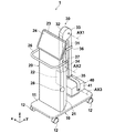
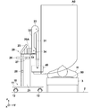
- FIG. 1 is a perspective view showing an overall shape of a radiation irradiation apparatus according to an embodiment of the present invention when not in use
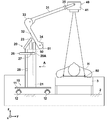
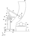
- FIG. 2 is a side view showing a state when the radiation irradiation apparatus according to the embodiment of the present invention is in use.
- the upper and lower sides in the vertical direction are referred to as “upper” and “lower”, respectively, and the same state
- a coordinate system is set in which the vertical direction is the z direction, the horizontal direction in FIG. 2 is the y direction, and the direction perpendicular to the paper surface in FIG.
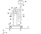
- the radiation irradiation apparatus 1 includes a leg portion 10, a main body portion 20, an arm portion 30, and a radiation source portion 40.
- the leg portion 10 can travel on the device mounting surface 2 and has a plate-like pedestal 11 and four wheel portions 12 attached to the four corners of the lower surface of the pedestal 11.
- the wheel portion 12 is made of a rubber tire or the like, and is attached to the pedestal 11 so as to be rotatable in a horizontal plane around an axis extending in the vertical direction. Thereby, the leg part 10 can be run on the apparatus mounting surface 2 in an arbitrary direction.
- the main body 20 is erected on the leg 10 and includes a housing 21.
- a control device that controls driving of the radiation irradiation device 1 and a battery (hereinafter simply referred to as a control device 22) are housed.
- the control device 22 controls the generation and irradiation of radiation such as tube current, irradiation time and tube voltage in the radiation source unit 40, and control related to acquisition of radiation images such as image processing on the radiation image acquired by the radiation detector 80. It is a device for performing.
- the control device 22 is configured by, for example, a computer in which a control program is installed, dedicated hardware, or a combination of both.
- a monitor 23 is attached to the upper surface of the casing 21.
- a handle 26 for pushing and pulling the radiation irradiating apparatus 1 is attached to the upper portion of the housing 21 by an adapter 27.
- omnidirectional cameras 28 for taking omnidirectional images of the apparatus 1 are attached to both side surfaces of the main body 20. In FIGS. 1 and 2, only one omnidirectional camera 28 is shown.
- the monitor 23 is composed of a liquid crystal panel or the like, and displays a radiographic image acquired by imaging the subject H and various information necessary for controlling the apparatus 1.
- the monitor 23 includes a touch panel type input unit 24 and receives input of various instructions necessary for the operation of the apparatus 1. Specifically, an input for setting imaging conditions and an input for imaging, that is, radiation emission are accepted.
- the monitor 23 corresponds to display means.
- the monitor 23 is attached to the upper surface of the main body 20 so that the tilt and rotation position can be changed. Further, instead of the touch panel type input unit 24, buttons or the like for performing various operations may be provided as the input unit 24.
- the arm part 30 is supported by the main body part 20. Specifically, the arm portion 30 is supported on the surface of the main body portion 20 opposite to the handle 26, that is, the right surface 20A in FIG. For this reason, in this embodiment, the main-body part 20 comprises the arm support part by this invention.
- the arm unit 30 can be moved up and down with respect to the main body unit 20 by the lifting mechanism 50.
- the arm unit 30 includes a first arm 31, a second arm 32, a first rotation unit 33, a second rotation unit 34, and an attachment unit 35.
- the radiation source section 40 is connected to the tip of the first arm 31 by a mounting section 35.
- the end on the radiation source 40 side of the first arm 31 is the upper end
- the end on the second arm 32 is the lower end.
- an end portion on the first arm 31 side of the second arm 32 is an upper end portion and an end portion on the main body portion 20 side is a lower end portion.
- the first arm 31 and the second arm 32 are connected by a first rotation part 33 so as to be rotatable around a rotation axis AX1.
- the rotation axis AX1 is an axis extending in the x direction.
- the first arm 31 rotates about the rotation axis AX1 so that the angle formed with the second arm 32 is changed.
- the first rotation unit 33 holds both the first arm 31 and the second arm 32 so that the first arm 31 rotates through a friction mechanism. Therefore, the first arm 31 can be rotated by applying a strong external force to some extent, and does not rotate unless an external force is applied, and maintains a relative angle with respect to the second arm 32.
- the second arm 32 is connected to the adapter 51 attached to the upper end portion of the lifting mechanism 50 via the second rotation portion 34 so as to be rotatable around the rotation axis AX2.
- the rotation axis AX2 is an axis extending in the x direction.
- the second arm 32 rotates about the rotation axis AX2 so that the angle formed with the surface 20A of the main body 20 on the side where the arm unit 30 is supported is changed.
- the second rotating part 34 holds both the arm 32 so that the second arm 32 rotates with respect to the main body part 20 via a friction mechanism. For this reason, the 2nd rotation part 34 can be rotated by applying a strong external force to some extent, does not rotate unless an external force is applied, and maintains the relative angle with respect to the main body part 20.
- FIG. 3 is a view taken in the direction of arrow A in FIG. As shown in FIG. 3, a groove 29 through which the adapter 51 can pass when the lifting mechanism 50 moves up and down is formed on the right side surface 20 ⁇ / b> A of the main body 20 in FIG. 2. In FIG. 3, the monitor 23 and the arm part 30 are omitted for the sake of explanation.
- the attachment portion 35 has a U shape and is attached to the tip of the first arm 31.
- the radiation source unit 40 is connected to the distal end of the first arm 31 via the attachment unit 35 so as to be rotatable around the rotation axis AX3.
- the rotation axis AX3 is an axis extending in the x direction.
- the radiation source section 40 rotates about the rotation axis AX3 so that the angle formed with the first arm 31 is changed.
- the attachment portion 35 holds both the radiation source portion 40 and the first arm 31 so as to rotate via a friction mechanism. For this reason, the radiation source unit 40 can be rotated by applying a strong external force to some extent, and does not rotate unless an external force is applied, and maintains a relative angle with respect to the first arm 31.
- the rotation between the first arm 31, the second arm 32, and the radiation source unit 40 is performed via a friction mechanism, but the rotation position may be fixed by a known lock mechanism. In this case, the rotation between the first arm 31, the second arm 32, and the radiation source unit 40 becomes possible by releasing the lock mechanism. Then, the rotation position can be fixed by locking the lock mechanism at the desired rotation position.
- the arm unit 30 is at the lowest position in the lifting mechanism 50. Further, the rotation position of the arm unit 30 is in the initial rotation position.
- the initial rotation position is a rotation position of the arm unit 30 when the first arm 31 and the second arm 32 are folded.
- Rotation position In the initial rotation position, the second arm 32 is rotated such that the first rotation part 33 is positioned above the second rotation part 34.
- the first arm 31 and the second arm 32 are connected by the connecting belt 36.
- one end of the connecting belt 36 is attached to the second arm 32, and a hook-and-loop fastener is attached to the other end.
- a hook-and-loop fastener corresponding to the hook-and-loop fastener of the connecting belt 36 is attached to the opposite surface of the first arm 31 in FIG.
- the connecting belt 36 is turned from the right side surface of the first arm 31 in FIG. 1 to the opposite side surface to connect the surface fastener of the connecting belt 36 and the surface fastener attached to the first arm 31.
- the first arm 31 does not rotate with respect to the second arm 32 in the initial rotation position.
- the connecting belt 36 corresponds to the first rotating portion regulating means.
- the radiation source unit 40 is configured by housing a radiation source, a collimator for narrowing the radiation irradiation range, and the like in a housing 41.
- the radiation source includes, for example, an X-ray tube, a booster circuit, a cooling unit that cools the X-ray tube, and the like. Radiation emission from the radiation source of the radiation source unit 40 is performed by an instruction from the input unit 24 of the monitor 23 by the operator.
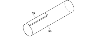
- the lifting mechanism 50 includes an outer cylinder 52 attached to the inside of the main body 20, a shaft 53 fitted to the outer cylinder 52, and an adapter 51 attached to the upper end portion of the shaft 53. Prepare. Note that a hole 56 is formed in the adapter 51 at a position that becomes the rotation axis AX ⁇ b> 2 of the second rotation portion 34.
- the shaft 53 is movable in the vertical direction with respect to the outer cylinder 52, and the vertical position of the shaft 53 with respect to the outer cylinder 52 can be fixed at a desired position by a lock mechanism (not shown). .
- a key groove 54 is formed on the outer cylinder 52, and a key 55 that engages with the key groove 54 is formed on the shaft 53.
- the key 55 is formed in a predetermined length from the upper end of the shaft 53.
- the key 55 has such a length that the lower end of the key 55 is positioned above the upper end of the outer cylinder 52 in a state where the shaft 53 has reached the highest position. For this reason, until the shaft 53 reaches the highest position, the key 55 engages with the key groove 54, so that the shaft 53 does not rotate around the central axis with respect to the outer cylinder 52.
- the key 55 is disengaged from the key groove 54, so that the shaft 53 can rotate with respect to the outer cylinder 52 around its central axis.
- the arm part 30 attached to the lifting mechanism 50 can turn with respect to the main body part 20.
- the turning means rotation around the axis of the shaft 53, that is, the z-axis that is the axis perpendicular to the device mounting surface 2.
- the key groove 54 of the outer cylinder 42 and the key 55 of the shaft 53 correspond to the turning restricting means.
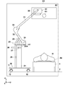
- a radiation detector 80 is disposed under the subject H lying on the bed 3, and radiation emitted from the radiation source unit 40 (for example, X Line) is applied to the radiation detector 80 through the subject H.
- the radiation detector 80 and the radiation irradiation apparatus 1 are connected by wire or wirelessly. As a result, the radiation image of the subject H acquired by the radiation detector 80 is directly input to the apparatus 1.
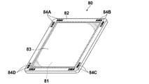
- FIG. 7 is an external perspective view of the radiation detector as seen from the front surface on the radiation irradiation side.
- the radiation detector 80 is a cassette-type radiation detector including a housing 82 that houses the image detection unit 81.
- the image detection unit 81 includes a scintillator (phosphor) that converts incident radiation into visible light, and a TFT (Thin Transistor) active matrix substrate.
- a scintillator phosphor
- TFT Thin Transistor
- the housing 82 has a gate driver that applies a gate pulse to the gate of the TFT to switch the TFT, and converts the electric charge accumulated in the pixel into an analog electric signal representing an X-ray image.
- An imaging control unit or the like having a signal processing circuit and the like for output is incorporated.
- the casing 82 has a size conforming to an international standard ISO (International Organization for Standardization) 4090: 2001, which is almost the same as, for example, a film cassette, an IP (Imaging Plate) cassette, or a CR (Computed Radiography) cassette. .
- Markers 84A to 84D representing identification information for identifying the radiation detector 80 are attached to the four corners of the front surface 82A of the housing 82.
- the markers 84A to 84D are each composed of two orthogonal barcodes.
- the radiation irradiation apparatus 1 is carried to the use position while running on the apparatus placement surface 2 such as a hospital floor by the wheel part 12 of the leg part 10 while being in the non-use state shown in FIG.
- the wheel portion 12 is attached to the pedestal 11 so as to be turnable as described above, the radiation irradiation apparatus 1 can be moved in the front-rear and left-right directions, and can be moved so as to be largely curved. It is also possible to turn on the spot. Therefore, it can be quickly brought to the use position in a state where a small turn is effective.
- the radiographic image is taken on the subject H lying on the bed 3 as shown in FIG.
- the radiation irradiation apparatus 1 When the radiation irradiation apparatus 1 is set near the subject H, the radiation irradiation apparatus 1 can be moved in the height direction of the subject H by the wheel portion 12. Thereby, the radiation irradiation apparatus 1 can be easily set in the optimal position.
- 8 to 11 are schematic side views for explaining the operation of moving the arm unit 30 and the radiation source unit 40 in the radiation irradiation apparatus 1.
- 8 to 11 are side views of the device 1 as viewed in the x direction.
- 8 to 11 also show the movable range A0 of the arm part 30 and the radiation source part 40 viewed in the x direction.
- the arm unit 30 is at the lowest position by the lifting mechanism 50.
- the pivot position of the arm portion is at the initial pivot position described above.
- the state in which the arm unit 30 is at the lowest position by the elevating mechanism 50 and is in the above-described initial rotation position is defined as the initial position of the arm unit 30. As shown in FIG.
- the movable range A ⁇ b> 0 of the radiation source unit 40 overlaps the subject H and the bed 3 at the initial position of the arm unit 30. For this reason, when the second arm 32 rotates toward the main body 20, the radiation source 40 collides with the subject H and the bed 3.
- the second arm 32 when the arm unit 30 is not at the highest highest position in the lifting range that is lifted and lowered by the lifting mechanism 50, the second arm 32 is turned by the second turning unit 34 from the initial turning position. Is regulated. That is, when the second arm 32 is rotated toward the main body 20 around the rotation axis AX2, the second arm 32 collides with the surface 20A on the side where the arm 30 of the main body 20 is supported. When the arm unit 30 is at the lowest position, the second arm 32 cannot be rotated from the initial rotation state of the arm unit 30. For this reason, the second arm 32 cannot be rotated around the rotation axis AX2 to move the radiation source unit 40 upward. Note that the surface 20A on the side of the main body portion 20 on which the arm portion 30 is supported constitutes the regulating means of the present invention.
- FIG. 9 is a side view showing a state in which the arm portion 30 is raised to the highest position, which is the first position. In this state, the movable range A0 of the radiation source unit 40 overlaps the subject H.
- the arm portion 30 is at the highest position, if the second arm 32 is rotated about the rotation axis AX2 in the counterclockwise direction in the drawing from the initial rotation state, The two arms 32 do not collide with the surface 20A of the main body 20 on the side where the arm 30 is supported. For this reason, as shown in FIG.
- the second arm 32 can be rotated around the rotation axis AX ⁇ b> 2 beyond the main body 20.
- the radiation source unit 40 moves to the upper left side of the subject H, away from the subject H.
- the operator removes the connecting belt 36 and rotates the first arm 31 around the rotation axis AX1, thereby causing the radiation source to collide with the subject H and the bed 3 as shown in FIG.
- the part 40 can be moved further upward.
- the operator pulls the radiation source section 40 in the y direction to rotate the first arm 31 and the second arm 32 around the rotation axis AX1 and the rotation axis AX2, respectively.
- the radiation source unit 40 can be moved to the target position P1 directly above.
- the radiation source unit 40 is driven by an instruction from the input unit 24 to irradiate the subject H with radiation, and the radiation transmitted through the subject H is radiated.
- a radiation image of the subject H can be acquired by detection by the detector 80.
- the arm part 30 when the arm part 30 is in the first position raised by the lifting mechanism 50, that is, in a position other than the highest position, the initial rotation of the second arm 32 by the second rotating part 34 is performed.
- the rotation from the moving position is restricted.
- the arm part 30 and the radiation source part 40 do not move. Therefore, it is possible to prevent the arm unit 30 and the radiation source unit 40 from moving and colliding with the subject H and the bed 3 when the arm unit 30 is located at a position other than the highest position.
- the 2nd arm 32 when the arm part 30 exists in the highest position, the 2nd arm 32 can be rotated to the main-body part 20 side.
- the radiation source unit 40 can be easily moved to a desired position.
- the configuration of the device 1 can be simplified.
- connection belt 36 may restrict the first arm 31 from rotating with respect to the second arm 32 and moving the first arm 31 and the radiation source unit 40 away from the second arm 32. Therefore, it is possible to more reliably prevent the first arm 31 and the radiation source unit 40 from moving and colliding with the bed 3 of the subject H.
- the movable range A0 of the arm unit 30 and the radiation source unit 40 shown in FIGS. 8 to 11 may be displayed on the monitor 23.
- Sensors that respectively detect the second rotation angle that is the rotation angle of the two arms 32 are provided in the arm unit 30.
- the omnidirectional camera 28 captures an image of the entire periphery of the apparatus 1 and inputs an image acquired by the capture to the control device 22 of the main body unit 20.
- the control device 22 since the two omnidirectional cameras 28 are attached to the main body unit 20, two images are input to the control device 22.
- the control device 22 creates a side image A1 when the radiation irradiation device 1 is viewed from the side, from the two input images.
- the sensor includes a position of the second rotation unit 34 by the lifting mechanism 50, a first rotation angle that is a rotation angle of the first arm 31 with respect to the first rotation unit 33, and a second with respect to the second rotation unit 34.
- the second rotation angle that is the rotation angle of the arm 32 is detected.
- the first and second rotation angles are angles based on, for example, the lifting position and the rotation position at the initial position of the arm unit 30 described above.
- the sensor inputs the detected position of the second rotation unit 34, the first rotation angle, and the second rotation angle to the control device 22.
- the lengths of the first and second arms 31, 32 and the size of the radiation source unit 40 are stored in advance. And the control apparatus 22 is based on the position of the 2nd rotation part 34 input from the sensor, the 1st rotation angle, the 2nd rotation angle, and the length of the 1st and 2nd arms 31 and 32.
- the movable range A0 of the arm part 30 and the radiation source part 40 is calculated.
- the control device 22 generates a combined side image in which the calculated movable range A0 of the arm unit 30 and the radiation source unit 40 is superimposed on the side image A1, and displays the combined side image on the monitor 23.
- FIG. 12 is a diagram showing a combined side image.
- SID Source Image Receptor Distance
- the control device 22 may display the target position P1 of the radiation source unit 40 based on the SID together with the side image A1 or the combined side image.
- a value measured in advance from the device mounting surface 2 may be input to the control device 22.
- the composite side image obtained by combining the movable range A0 of the radiation source unit 40 with the side image A1 when the arm unit 30 is viewed from the side is displayed on the monitor 23, so that the operator can see the radiation source unit 40. Can be recognized. Accordingly, since the source unit 40 can be moved to a desired position while checking the movable range A0 of the source unit 40, the source unit 40 moves and collides with the bed 3 or the like of the subject H. It can prevent more reliably.
- the radiation source section 40 can be easily set to the target position P1. Can move.
- the control device 22 may display the combined side image on the monitor 23 when at least one variation of the moving angle and the second rotation angle is detected by the sensor.
- a sensor for detecting connection and disconnection of the connecting belt 36 may be provided so that the combined side image is displayed on the monitor 23 when the connecting belt 36 is changed from the connected state to the disconnected state.
- the operator when operating the arm unit 30, the operator moves to the side of the device 1 to perform work. For this reason, you may comprise so that the direction of the display surface of the monitor 23 can face the side of the apparatus 1.
- FIG. Thereby, the operator can easily confirm the combined side image displayed on the monitor 23 while operating the arm unit 30.
- a sensor for detecting that the display surface of the monitor 23 is directed to the side is provided, and when this sensor detects that the display surface of the monitor 23 is directed to the side, the controller 22 monitors the display surface.
- the synthesized side image may be displayed on the screen 23.
- the control device 22 may detect whether or not the radiation source unit 40 has moved to the target position P1. In this case, when it is detected that the radiation source unit 40 has moved to the target position P1, the display on the monitor 23 may be switched from the combined side image to the display of various information necessary for control of the apparatus 1. .
- the main body portion 20 constitutes the restricting means of the present invention.
- the arm portion 30 is at a position other than the highest highest position by the lifting mechanism 50, the second time You may make it provide the mechanism which locks rotation of the moving part 34 as a control means.
- the main body portion 20 constitutes an arm support portion according to the present invention, but separately from the main body portion 20, an arm support portion that supports the arm portion 30 is erected on the leg portion 10. May be provided.
- the second arm 32 can be rotated when the arm portion 30 is raised by the elevating mechanism 50.
- the second arm 32 is not limited to the highest position.
- the second arm 32 may be rotatable at any position close to the highest position.
- the rotation of the first arm 31 by the first rotation unit 33 is restricted by the connecting belt 36, but other means such as a lock mechanism may be used.
- the initial rotation position may be the initial rotation position of the arm unit 30.
- the second arm 32 is restricted from rotating clockwise in FIG. 14, and when the arm portion 30 is at the highest position, the rotation of the second arm 32 is restricted. What is necessary is just to provide the locking mechanism which enables a movement.
- the initial rotation position is a position where the second arm is rotated upward with respect to the arm support portion, by restricting the rotation of the second arm to the arm support portion side, the arm portion and the radiation source portion are , It does not move toward the subject and the bed. For this reason, when the arm unit is located at a position other than the first position, the arm unit and the radiation source unit can be prevented from moving toward the subject and the bed and colliding with the subject and the bed.
- the restricting means releases the restriction of the rotation of the second arm toward the arm supporting portion by the second rotating portion, so that the second arm is the arm supporting portion. It can be rotated beyond.
- the arm unit and the radiation source unit can move upward through positions away from the subject and the bed, so that the arm unit and the radiation source unit collide with the subject and the bed and the like. Can be prevented more reliably.
- the restricting means is made of the surface of the arm support portion on the side where the arm portion is supported, it is not necessary to separately provide a means for restricting the rotation of the second arm. Can be simplified.
- the radiation source portion can be moved in the direction of lifting after the radiation source portion has moved to the highest position. For this reason, it can prevent more reliably that a radiation source part moves and collides with a subject, a bed, etc.
- the arm support portion is a main body portion including a control means for controlling the radiation source portion, it is not necessary to separately provide a member having a function as the arm support portion. It can be.
- the arm part when the arm part is located at a position other than the first position, even when the arm part can be turned by restricting the turning of the arm part, the arm part is located outside the first position. In addition, it is possible to prevent the radiation source unit from moving due to turning and colliding with the subject and the bed.
- the first arm rotates with respect to the second arm, and the first arm and the radiation source part move in a direction away from the second arm. Since it can regulate, it can prevent more reliably that a 1st arm and a source part move and collide with a subject, a bed, etc., when an arm part exists in other than a 1st position.
- the operator can recognize the movable range of the arm unit and the radiation source unit by displaying on the display means the movable range of the arm unit and the radiation source unit when the arm unit is viewed from the side. .
- the operator can recognize the movable range of the arm unit and the radiation source unit by displaying on the display means the movable range of the arm unit and the radiation source unit when the arm unit is viewed from the side. .
- it is possible to move the radiation source unit to a desired position while confirming the movable range. Therefore, it is possible to more reliably prevent the arm part and the radiation source part from moving and colliding with the subject and the bed.
- the radiation source portion can be easily moved to the target position.
Landscapes
- Health & Medical Sciences (AREA)
- Life Sciences & Earth Sciences (AREA)
- Engineering & Computer Science (AREA)
- Medical Informatics (AREA)
- Radiology & Medical Imaging (AREA)
- Molecular Biology (AREA)
- Biophysics (AREA)
- Nuclear Medicine, Radiotherapy & Molecular Imaging (AREA)
- Optics & Photonics (AREA)
- Pathology (AREA)
- Physics & Mathematics (AREA)
- Biomedical Technology (AREA)
- Heart & Thoracic Surgery (AREA)
- High Energy & Nuclear Physics (AREA)
- Surgery (AREA)
- Animal Behavior & Ethology (AREA)
- General Health & Medical Sciences (AREA)
- Public Health (AREA)
- Veterinary Medicine (AREA)
- Human Computer Interaction (AREA)
- Automation & Control Theory (AREA)
- Robotics (AREA)
- Apparatus For Radiation Diagnosis (AREA)
Priority Applications (4)
| Application Number | Priority Date | Filing Date | Title |
|---|---|---|---|
| EP16830054.9A EP3329849B1 (de) | 2015-07-27 | 2016-07-26 | Strahlungsemittierende vorrichtung |
| CN201680043798.5A CN107920791B (zh) | 2015-07-27 | 2016-07-26 | 放射线照射装置 |
| JP2017531016A JP6479987B2 (ja) | 2015-07-27 | 2016-07-26 | 放射線照射装置 |
| US15/865,544 US10765388B2 (en) | 2015-07-27 | 2018-01-09 | Radiation-irradiation device comprising a first arm, a second arm, and main body surface regulating a rotational movement of the second arm |
Applications Claiming Priority (2)
| Application Number | Priority Date | Filing Date | Title |
|---|---|---|---|
| JP2015147524 | 2015-07-27 | ||
| JP2015-147524 | 2015-07-27 |
Related Child Applications (1)
| Application Number | Title | Priority Date | Filing Date |
|---|---|---|---|
| US15/865,544 Continuation US10765388B2 (en) | 2015-07-27 | 2018-01-09 | Radiation-irradiation device comprising a first arm, a second arm, and main body surface regulating a rotational movement of the second arm |
Publications (1)
| Publication Number | Publication Date |
|---|---|
| WO2017017949A1 true WO2017017949A1 (ja) | 2017-02-02 |
Family
ID=57884493
Family Applications (1)
| Application Number | Title | Priority Date | Filing Date |
|---|---|---|---|
| PCT/JP2016/003454 WO2017017949A1 (ja) | 2015-07-27 | 2016-07-26 | 放射線照射装置 |
Country Status (5)
| Country | Link |
|---|---|
| US (1) | US10765388B2 (de) |
| EP (1) | EP3329849B1 (de) |
| JP (1) | JP6479987B2 (de) |
| CN (1) | CN107920791B (de) |
| WO (1) | WO2017017949A1 (de) |
Cited By (1)
| Publication number | Priority date | Publication date | Assignee | Title |
|---|---|---|---|---|
| JP2018033487A (ja) * | 2016-08-29 | 2018-03-08 | 株式会社日立製作所 | 移動型x線装置 |
Families Citing this family (2)
| Publication number | Priority date | Publication date | Assignee | Title |
|---|---|---|---|---|
| DE102016013315A1 (de) | 2016-11-08 | 2018-05-09 | RayScan Technologies GmbH | Messsystem und Verfahren zum Betreiben eines Messsystems |
| US10925561B2 (en) * | 2017-11-17 | 2021-02-23 | Konica Minolta Healthcare Americas, Inc. | Portable digital radiography apparatus comprising a frame including a base, a digital radiography panel, and a computer |
Citations (4)
| Publication number | Priority date | Publication date | Assignee | Title |
|---|---|---|---|---|
| US3801790A (en) * | 1972-03-15 | 1974-04-02 | Siemens Ag | Movable x-ray examining device |
| JPS5283673U (de) * | 1975-12-18 | 1977-06-22 | ||
| JPS602505U (ja) * | 1983-06-20 | 1985-01-10 | 株式会社 日立メデイコ | 電動移動形x線装置 |
| JP2014073322A (ja) * | 2012-10-05 | 2014-04-24 | Canon Inc | 放射線発生装置 |
Family Cites Families (63)
| Publication number | Priority date | Publication date | Assignee | Title |
|---|---|---|---|---|
| JP2000041976A (ja) * | 1998-07-31 | 2000-02-15 | Shimadzu Corp | 移動型x線装置 |
| US6237707B1 (en) * | 1999-02-18 | 2001-05-29 | Hologic, Inc. | Motion controlling system for motorized medical equipment carriage |
| JP3888203B2 (ja) * | 2002-04-02 | 2007-02-28 | 株式会社島津製作所 | 回診用x線装置 |
| JP2004073354A (ja) * | 2002-08-13 | 2004-03-11 | Canon Inc | X線画像撮影装置 |
| JP4612832B2 (ja) * | 2004-12-03 | 2011-01-12 | キヤノン株式会社 | 放射線撮影装置及びその制御方法 |
| CN201019755Y (zh) * | 2006-12-25 | 2008-02-13 | 南京普爱射线影像设备有限公司 | 一种移动式医用x射线摄影机 |
| WO2009104656A1 (ja) * | 2008-02-22 | 2009-08-27 | 株式会社 日立メディコ | 移動型x線装置 |
| US8419276B2 (en) * | 2008-02-22 | 2013-04-16 | Hitachi Medical Corporation | Mobile X-ray apparatus |
| EP2408375B1 (de) * | 2009-03-20 | 2017-12-06 | Orthoscan Incorporated | Bewegliche bildgebungsvorrichtung |
| FR2953119B1 (fr) * | 2009-12-01 | 2012-07-27 | Gen Electric | Base mobile et appareil a rayons x monte sur une telle base mobile |
| DE102010008552B4 (de) * | 2010-02-19 | 2014-11-13 | Siemens Aktiengesellschaft | Röntgensystem |
| JP5506481B2 (ja) | 2010-03-19 | 2014-05-28 | 株式会社日立メディコ | 移動型x線装置 |
| US8568028B2 (en) * | 2010-04-13 | 2013-10-29 | Carestream Health, Inc. | Mobile radiography unit having collapsible support column |
| US8961011B2 (en) * | 2010-04-13 | 2015-02-24 | Carestream Health, Inc. | Mobile radiography unit having multiple monitors |
| WO2011136094A1 (ja) * | 2010-04-26 | 2011-11-03 | 株式会社 日立メディコ | 移動型x線装置及び移動型x線装置の制御方法 |
| US8840304B2 (en) * | 2010-06-14 | 2014-09-23 | General Electric Company | Positioner for ultra-portable imaging system |
| JP5665405B2 (ja) | 2010-07-30 | 2015-02-04 | 富士フイルム株式会社 | 放射線画像撮影システム及び画像表示方法 |
| US8622614B2 (en) * | 2010-08-23 | 2014-01-07 | Carestream Health, Inc. | Locking device for mobile X-ray system |
| WO2012082799A1 (en) * | 2010-12-13 | 2012-06-21 | Orthoscan, Inc. | Mobile fluoroscopic imaging system |
| NL2005906C2 (en) * | 2010-12-22 | 2012-06-25 | Nucletron Bv | A mobile x-ray unit. |
| US8721176B2 (en) * | 2011-05-06 | 2014-05-13 | General Electric Company | Rechargeable image detector system and method |
| KR102028769B1 (ko) * | 2011-09-12 | 2019-10-04 | 케어스트림 헬스 인코포레이티드 | 이동식 라디오그래피 촬영 장치에 저장된 전기적 그리드 홀더와 감지기들을 위한 충전기 및 이를 이용하기 위한 방법 |
| EP2760341B1 (de) * | 2011-11-15 | 2017-02-01 | Solutions for Tomorrow AB | Vorrichtung zur erzeugung von röntgenbildern |
| US9198270B2 (en) * | 2011-11-18 | 2015-11-24 | Virtual Imaging, Inc. | Radiographic imaging apparatus with distributed antenna system |
| JP5917162B2 (ja) * | 2012-01-19 | 2016-05-11 | キヤノン株式会社 | X線撮影装置 |
| US9078597B2 (en) * | 2012-04-05 | 2015-07-14 | General Electric Company | Mobile x-ray unit with integrated x-ray shield |
| US9693437B2 (en) * | 2012-04-13 | 2017-06-27 | General Electric Company | Systems and methods for controlling X-ray imaging systems |
| US8899834B2 (en) * | 2012-04-18 | 2014-12-02 | General Electric Company | Pivot joint brakes for X-ray positioning system |
| EP2840973B1 (de) * | 2012-04-24 | 2017-06-28 | Portavision Medical LLC | Mobiles bildgebungssystem und verfahren |
| US9788810B2 (en) * | 2015-06-25 | 2017-10-17 | Portavision Medical Llc | System and method for X-ray imaging alignment |
| US8944681B2 (en) * | 2012-05-03 | 2015-02-03 | General Electric Company | Mobile X-ray machine with an anticollision device |
| JP6000787B2 (ja) * | 2012-09-28 | 2016-10-05 | キヤノン株式会社 | 放射線画像撮影装置および放射線画像撮影装置の制御方法 |
| JP6238611B2 (ja) * | 2012-09-28 | 2017-11-29 | キヤノン株式会社 | 移動型放射線撮影装置、放射線撮影システム、及び制御方法 |
| EP2903526B1 (de) * | 2012-10-02 | 2017-09-13 | Carestream Health, Inc. | Drahtlose bildgebung mit schneller frame-rate |
| JP2014073310A (ja) * | 2012-10-05 | 2014-04-24 | Canon Inc | 移動型x線画像撮影装置 |
| JP2014083108A (ja) * | 2012-10-19 | 2014-05-12 | Canon Inc | 移動型のx線画像撮影装置 |
| JP6222960B2 (ja) * | 2012-11-12 | 2017-11-01 | キヤノン株式会社 | 放射線発生用装置及び放射線撮影装置 |
| JP2014155620A (ja) * | 2013-02-15 | 2014-08-28 | Canon Inc | 移動型x線発生装置 |
| WO2014132362A1 (ja) * | 2013-02-27 | 2014-09-04 | 株式会社島津製作所 | X線撮影装置 |
| KR102121721B1 (ko) * | 2013-03-04 | 2020-06-26 | 삼성전자주식회사 | 이동형 엑스선 영상 장치 및 그 제어 방법 |
| US9456799B2 (en) * | 2013-03-08 | 2016-10-04 | Virtual Imaging, Inc. | Modality with multicomputer system and powering sequence therefor |
| JP2014195590A (ja) * | 2013-03-29 | 2014-10-16 | キヤノン株式会社 | 放射線発生用装置、放射線撮影装置、コンピュータプログラム及び記憶媒体 |
| US9480445B2 (en) * | 2013-05-14 | 2016-11-01 | Solutions For Tomorrow Ab | Elevating column and method of controlling elevation thereof |
| CA2877381C (en) * | 2013-07-04 | 2023-08-15 | Sociedad Espanola De Electromedicina Y Calidad, S.A. | Mobile x-ray device with telescopic column |
| US9413961B2 (en) * | 2013-09-03 | 2016-08-09 | Swissray Asia Healthcare Co., Ltd. | Articulating display and control monitor device for a mobile radiographic machine |
| JP6324009B2 (ja) * | 2013-09-12 | 2018-05-16 | キヤノン株式会社 | 放射線発生用装置及び放射線撮影装置 |
| JP5965382B2 (ja) * | 2013-12-18 | 2016-08-03 | 株式会社モリタ製作所 | X線ct撮影装置 |
| EP2910189B1 (de) * | 2014-02-21 | 2016-09-14 | Samsung Electronics Co., Ltd | Röntgenrasterstruktur und röntgenvorrichtung damit |
| JP6546397B2 (ja) * | 2014-03-20 | 2019-07-17 | キヤノン株式会社 | 放射線発生用装置 |
| US10058303B2 (en) * | 2014-04-03 | 2018-08-28 | Hitachi, Ltd. | Mobile X-ray imaging apparatus |
| JP2015217112A (ja) * | 2014-05-16 | 2015-12-07 | キヤノン株式会社 | 移動型放射線撮影装置及び移動型放射線発生用装置 |
| JP6548451B2 (ja) * | 2014-07-07 | 2019-07-24 | キヤノンメディカルシステムズ株式会社 | 移動型x線診断装置 |
| US10271802B2 (en) * | 2014-08-12 | 2019-04-30 | Carestream Health, Inc. | Digital x-ray imaging apparatus and method |
| US10433805B2 (en) * | 2014-09-03 | 2019-10-08 | Shimadzu Corporation | X-ray imaging apparatus for rounds |
| KR102089370B1 (ko) * | 2014-09-23 | 2020-03-16 | 삼성전자주식회사 | 수납장치 및 이를 구비하는 엑스선 촬영기기 |
| WO2016060490A1 (en) * | 2014-10-17 | 2016-04-21 | Samsung Electronics Co., Ltd. | X-ray imaging apparatus, method of controlling the same, and x-ray imaging system |
| US10292673B2 (en) * | 2015-02-25 | 2019-05-21 | J. Morita Manufacturing Corporation | Medical X-ray photographing apparatus and X-ray photographing method |
| US10278654B2 (en) * | 2015-02-25 | 2019-05-07 | J. Morita Manufacturing Corporation | Medical X-ray photographing apparatus and X-ray photographing method |
| JP6395650B2 (ja) * | 2015-03-23 | 2018-09-26 | 株式会社日立製作所 | X線撮影装置 |
| JP6438333B2 (ja) * | 2015-03-23 | 2018-12-12 | 株式会社日立製作所 | 移動型x線撮影装置 |
| US9931089B2 (en) * | 2015-03-31 | 2018-04-03 | Fujifilm Corporation | Radiation irradiation apparatus |
| JP6438355B2 (ja) * | 2015-06-05 | 2018-12-12 | 富士フイルム株式会社 | 放射線撮影装置およびその作動方法、並びにコンソールおよびその作動方法 |
| US9655582B2 (en) * | 2015-07-14 | 2017-05-23 | Shimadzu Corporation | Radiographic apparatus |
-
2016
- 2016-07-26 EP EP16830054.9A patent/EP3329849B1/de active Active
- 2016-07-26 CN CN201680043798.5A patent/CN107920791B/zh active Active
- 2016-07-26 JP JP2017531016A patent/JP6479987B2/ja active Active
- 2016-07-26 WO PCT/JP2016/003454 patent/WO2017017949A1/ja unknown
-
2018
- 2018-01-09 US US15/865,544 patent/US10765388B2/en active Active
Patent Citations (4)
| Publication number | Priority date | Publication date | Assignee | Title |
|---|---|---|---|---|
| US3801790A (en) * | 1972-03-15 | 1974-04-02 | Siemens Ag | Movable x-ray examining device |
| JPS5283673U (de) * | 1975-12-18 | 1977-06-22 | ||
| JPS602505U (ja) * | 1983-06-20 | 1985-01-10 | 株式会社 日立メデイコ | 電動移動形x線装置 |
| JP2014073322A (ja) * | 2012-10-05 | 2014-04-24 | Canon Inc | 放射線発生装置 |
Cited By (1)
| Publication number | Priority date | Publication date | Assignee | Title |
|---|---|---|---|---|
| JP2018033487A (ja) * | 2016-08-29 | 2018-03-08 | 株式会社日立製作所 | 移動型x線装置 |
Also Published As
| Publication number | Publication date |
|---|---|
| EP3329849A1 (de) | 2018-06-06 |
| JP6479987B2 (ja) | 2019-03-06 |
| US10765388B2 (en) | 2020-09-08 |
| EP3329849A4 (de) | 2018-09-12 |
| US20180146940A1 (en) | 2018-05-31 |
| CN107920791B (zh) | 2020-11-06 |
| CN107920791A (zh) | 2018-04-17 |
| EP3329849B1 (de) | 2020-07-01 |
| JPWO2017017949A1 (ja) | 2018-04-26 |
Similar Documents
| Publication | Publication Date | Title |
|---|---|---|
| US10660584B2 (en) | Monitor image display method for radiation-irradiation device and radiation-irradiation device | |
| US10939884B2 (en) | Radiation emitting device comprising a computing unit for controlling an inclination and a rotation angle of a monitor, method for controlling radiation emitting device, and program | |
| JP5574589B2 (ja) | X線撮影装置 | |
| US10136866B2 (en) | Radiation irradiation device | |
| JP6411574B2 (ja) | 放射線照射装置 | |
| US10772587B2 (en) | Radiation irradiation device | |
| JP6145899B2 (ja) | 放射線画像撮影装置 | |
| JP6479987B2 (ja) | 放射線照射装置 | |
| JP6496029B2 (ja) | 放射線照射装置の搬送補助方法および搬送補助装置、並びに放射線画像撮影装置 | |
| JP6134992B2 (ja) | 放射線照射装置 | |
| US10674977B2 (en) | Radiographic imaging apparatus | |
| WO2017090453A1 (ja) | 放射線照射装置 | |
| WO2017077652A1 (ja) | 移動型x線装置 | |
| JP6791487B2 (ja) | X線検査システム及びx線照射装置 | |
| WO2017056486A1 (ja) | 放射線照射装置および放射線照射装置の操作補助方法 |
Legal Events
| Date | Code | Title | Description |
|---|---|---|---|
| 121 | Ep: the epo has been informed by wipo that ep was designated in this application |
Ref document number: 16830054 Country of ref document: EP Kind code of ref document: A1 |
|
| ENP | Entry into the national phase |
Ref document number: 2017531016 Country of ref document: JP Kind code of ref document: A |
|
| NENP | Non-entry into the national phase |
Ref country code: DE |