WO2017013885A1 - ステントグラフト - Google Patents
ステントグラフト Download PDFInfo
- Publication number
- WO2017013885A1 WO2017013885A1 PCT/JP2016/053172 JP2016053172W WO2017013885A1 WO 2017013885 A1 WO2017013885 A1 WO 2017013885A1 JP 2016053172 W JP2016053172 W JP 2016053172W WO 2017013885 A1 WO2017013885 A1 WO 2017013885A1
- Authority
- WO
- WIPO (PCT)
- Prior art keywords
- graft
- stent
- stent graft
- peripheral surface
- wire
- Prior art date
- Legal status (The legal status is an assumption and is not a legal conclusion. Google has not performed a legal analysis and makes no representation as to the accuracy of the status listed.)
- Ceased
Links
Images


Classifications
-
- A—HUMAN NECESSITIES
- A61—MEDICAL OR VETERINARY SCIENCE; HYGIENE
- A61F—FILTERS IMPLANTABLE INTO BLOOD VESSELS; PROSTHESES; DEVICES PROVIDING PATENCY TO, OR PREVENTING COLLAPSING OF, TUBULAR STRUCTURES OF THE BODY, e.g. STENTS; ORTHOPAEDIC, NURSING OR CONTRACEPTIVE DEVICES; FOMENTATION; TREATMENT OR PROTECTION OF EYES OR EARS; BANDAGES, DRESSINGS OR ABSORBENT PADS; FIRST-AID KITS
- A61F2/00—Filters implantable into blood vessels; Prostheses, i.e. artificial substitutes or replacements for parts of the body; Appliances for connecting them with the body; Devices providing patency to, or preventing collapsing of, tubular structures of the body, e.g. stents
- A61F2/02—Prostheses implantable into the body
- A61F2/04—Hollow or tubular parts of organs, e.g. bladders, tracheae, bronchi or bile ducts
- A61F2/06—Blood vessels
- A61F2/07—Stent-grafts
- A61F2002/072—Encapsulated stents, e.g. wire or whole stent embedded in lining
-
- A—HUMAN NECESSITIES
- A61—MEDICAL OR VETERINARY SCIENCE; HYGIENE
- A61F—FILTERS IMPLANTABLE INTO BLOOD VESSELS; PROSTHESES; DEVICES PROVIDING PATENCY TO, OR PREVENTING COLLAPSING OF, TUBULAR STRUCTURES OF THE BODY, e.g. STENTS; ORTHOPAEDIC, NURSING OR CONTRACEPTIVE DEVICES; FOMENTATION; TREATMENT OR PROTECTION OF EYES OR EARS; BANDAGES, DRESSINGS OR ABSORBENT PADS; FIRST-AID KITS
- A61F2/00—Filters implantable into blood vessels; Prostheses, i.e. artificial substitutes or replacements for parts of the body; Appliances for connecting them with the body; Devices providing patency to, or preventing collapsing of, tubular structures of the body, e.g. stents
- A61F2/02—Prostheses implantable into the body
- A61F2/04—Hollow or tubular parts of organs, e.g. bladders, tracheae, bronchi or bile ducts
- A61F2/06—Blood vessels
- A61F2/07—Stent-grafts
- A61F2002/077—Stent-grafts having means to fill the space between stent-graft and aneurysm wall, e.g. a sleeve
-
- A—HUMAN NECESSITIES
- A61—MEDICAL OR VETERINARY SCIENCE; HYGIENE
- A61F—FILTERS IMPLANTABLE INTO BLOOD VESSELS; PROSTHESES; DEVICES PROVIDING PATENCY TO, OR PREVENTING COLLAPSING OF, TUBULAR STRUCTURES OF THE BODY, e.g. STENTS; ORTHOPAEDIC, NURSING OR CONTRACEPTIVE DEVICES; FOMENTATION; TREATMENT OR PROTECTION OF EYES OR EARS; BANDAGES, DRESSINGS OR ABSORBENT PADS; FIRST-AID KITS
- A61F2250/00—Special features of prostheses classified in groups A61F2/00 - A61F2/26 or A61F2/82 or A61F9/00 or A61F11/00 or subgroups thereof
- A61F2250/0014—Special features of prostheses classified in groups A61F2/00 - A61F2/26 or A61F2/82 or A61F9/00 or A61F11/00 or subgroups thereof having different values of a given property or geometrical feature, e.g. mechanical property or material property, at different locations within the same prosthesis
- A61F2250/0023—Special features of prostheses classified in groups A61F2/00 - A61F2/26 or A61F2/82 or A61F9/00 or A61F11/00 or subgroups thereof having different values of a given property or geometrical feature, e.g. mechanical property or material property, at different locations within the same prosthesis differing in porosity
- A61F2250/0024—Special features of prostheses classified in groups A61F2/00 - A61F2/26 or A61F2/82 or A61F9/00 or A61F11/00 or subgroups thereof having different values of a given property or geometrical feature, e.g. mechanical property or material property, at different locations within the same prosthesis differing in porosity made from both porous and non-porous parts, e.g. adjacent parts
Definitions
- the present invention relates to a stent graft used in the treatment of, for example, arterial dissection (aneurysm).
- a stent made of a wire (elementary wire) or the like can be placed in the affected area to expand and maintain the lumen. (Stent placement) is used.
- a stent graft provided with a cylindrical graft covering such a stent is used (see, for example, Patent Document 1).
- Patent Document 2 discloses a stent graft that is inserted from the base of the patient's foot (buttock) and carried to the affected area (lesion site) as a stent graft for the thoracic aorta.
- the stent graft When inserting the stent graft from the buttock in this way, it is necessary to mount the stent graft having an outer diameter of, for example, about 20 to 46 mm on a fine catheter having a diameter of, for example, about 20 to 26 Fr (French). . Therefore, since it is necessary to reduce the outer diameter of the stent graft after the diameter reduction, the thickness of the graft in the stent graft is generally small (thin).
- OSG Open Stent Graft
- the aorta is incised after thoracotomy
- a stent graft is inserted from the incised portion
- the proximal end side of the stent graft is sutured to the patient's blood vessel
- the stent graft is further connected as necessary.
- the thickness of the graft is small as described above, the strength of the graft is insufficient.
- the graft may tear during suturing and the anastomosis may not be successful.
- blood leakage from the graft may increase, and arterial dissection may not be sufficiently treated. There is also. Therefore, a proposal that can improve the convenience of such treatment is desired.
- the present invention has been made in view of such problems, and an object of the present invention is to provide a stent graft capable of improving convenience during treatment.
- the stent graft of the present invention comprises a cylindrical graft and at least one stent made of one or more wires disposed at least in part of the graft, and the thickness of the graft is one or more of the wires in the stent. Is larger than the diameter of at least one of the wires.
- the thickness of the graft is larger than the diameter of at least one of the one or more wires in the stent.
- the graft of the present invention when the graft is arranged so as to cover at least the outer peripheral side of the stent, a part of the at least one wire having a diameter of more than half is embedded on the inner peripheral surface side of the graft. You may make it.
- the periphery of the stent is easily wrapped in the graft.
- the inner peripheral side of the stent is less likely to protrude from the inner peripheral surface of the graft, and blood flow in the stent graft is less likely to be hindered.
- the force applied from the stent is easily dispersed in the graft (the force buffering effect in the graft is increased), and the inside of the blood vessel is prevented from being damaged by the outer peripheral side of the stent.
- the liquid retaining property on the outer peripheral surface side of the graft may be larger than the liquid retaining property on the inner peripheral surface side of the graft.
- anastomosis between the graft and the patient's blood vessel or artificial blood vessel is facilitated, and adhesion between the graft and the inner peripheral surface of the blood vessel is improved.
- thrombus is less likely to occur on the inner peripheral surface side of the graft.
- the stent may be disposed in a partial region along the axial direction of the graft. In this case, it becomes easy to perform anastomosis between the stent graft and the patient's blood vessel or artificial blood vessel by using the non-arranged region of the stent in the graft.
- the thickness of the graft is larger than the diameter of at least one of the one or more wires in the stent, for example, arterial dissection using the OSG method, etc.
- the risk of tearing of the graft and blood leakage from the graft can be reduced. Therefore, convenience during treatment can be improved.
- FIG. 10 is a schematic cross-sectional view illustrating a configuration example of a stent graft according to Modification 1.
- FIG. 10 is a schematic perspective view illustrating a schematic configuration example of a stent graft according to Modification 2.
- FIG. 10 is a schematic perspective view illustrating a schematic configuration example of a stent graft according to Modification 2.
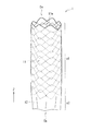
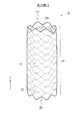
- FIG. 1 is a perspective view schematically showing a schematic configuration example of a stent graft (stent graft 1) according to an embodiment of the present invention.
- the stent graft 1 is an instrument used in the treatment of an arterial dissection using the OSG method, for example, and is placed in a site to be treated (for example, in a blood vessel such as an artery) as described later. .
- this stent graft 1 has a cylindrical (cylindrical) structure extending along the axial direction (Z-axis direction), and is configured by a stent 11 and a graft 12. .
- the length of the stent graft 1 along the axial direction is, for example, about 2 to 30 cm.
- the outer diameter of the stent graft 1 when expanded is, for example, about 6 to 46 mm.
- the stent 11 is configured using one or a plurality of wire rods 11w (elementary wires), and in this example, has a cylindrical (cylindrical) structure.
- this cylindrical structure is configured by a network structure, and such a cylindrical network structure is formed by braiding the wire 11 w in a predetermined pattern. Is formed. Examples of the braided pattern include plain weave, twill weave, and knitted knitting. Moreover, you may make it form a cylindrical mesh-like structure by arrange
- the stent 11 is disposed in a partial region along the axial direction of the graft 12.
- the stent graft 1 has, along the axial direction, a stent placement area a1 in which the stent 11 is placed and a stent non-placement area a2 in which the stent 11 is not placed.
- a stent non-arrangement region a ⁇ b> 2 is provided on the end Eb side that is one end of the stent graft 1, and an end that is the other end of the stent graft 1.
- the stent placement region a1 extends to the end Ea.
- the length of the stent 11 along the axial direction (the length of the stent placement region a1) is, for example, about 2 to 25 cm.
- a metal wire is preferable, and in particular, a shape memory alloy to which a shape memory effect and superelasticity by heat treatment are imparted is preferably employed.
- a shape memory alloy to which a shape memory effect and superelasticity by heat treatment are imparted
- stainless steel, tantalum (Ta), titanium (Ti), platinum (Pt), gold (Au), tungsten (W), or the like may be used as the material of the wire 11w depending on applications.
- An alloy such as X Fe, Cu, vanadium (V), cobalt (Co), etc. is preferably used.
- a wire 11w you may make it use a synthetic resin etc., for example.
- a composite wire in which the surface of a metal wire is coated with Au, Pt or the like by means such as plating, or a core made of a radiopaque material such as Au or Pt is covered with an alloy, 11w may be used.
- the graft 12 has a cylindrical shape (cylindrical shape), and is disposed so as to cover (cover) at least a part of the stent 11. Specifically, in this example, the graft 12 is disposed so as to cover the outer peripheral side of the stent 11 (wire material 11w).
- the graft 12 is connected to the stent 11 by means of sewing, adhesion, welding, or the like.
- the graft 12 covers and connects the stent 11 so as not to affect the expansion and contraction of the stent 11.
- the connection part of such a graft 12 and the stent 11 is suitably provided in the both ends of the stent 11, an intermediate part, etc., for example.
- thermoplastic resin formed into a cylindrical shape by a molding method such as extrusion molding or blow molding for example, a thermoplastic resin fiber formed into a cylindrical shape, or a knitted fabric made of ultrafine metal wires , Non-woven fabric made of thermoplastic resin and ultra-fine metal formed into a tubular shape, flexible resin sheet and porous sheet formed into a tubular shape, and resin dissolved in a solvent formed into a thin tubular shape by electrospinning Or the like can be used.
- knitted fabric As the knitted fabric described above, known knitted fabrics and woven fabrics such as plain weave and twill weave can be used. Moreover, the thing with a crimp, such as crimping, can also be used. Of these, knitted fabrics of thermoplastic resin fibers formed in a cylindrical shape, and plain weave fabrics of thermoplastic resin fibers formed in a cylindrical shape are particularly excellent in strength, porosity and productivity. It can be said that it is preferable.
- thermoplastic resin examples include polyolefins such as polyethylene, polypropylene, and ethylene- ⁇ -olefin copolymers, polyamides, polyurethanes, polyethylene terephthalate, polybutylene terephthalate, polycyclohexane terephthalate, polyethylene-2,6-naphthalate, and the like. Polyesters, fluororesins such as polyfluorinated ethylene and polyfluorinated propylene, and the like, and resins with little durability and tissue reaction can be used. Of these, in particular, polyesters such as polyethylene terephthalate and fluorine resins such as polyfluorinated ethylene and polyfluorinated propylene that are chemically stable and have high durability and little tissue reaction can be preferably used.
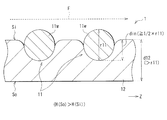
- FIG. 2 is a schematic cross-sectional view showing a detailed configuration example of the stent graft 1.
- the thickness d12 of the graft 12 is larger than the diameter r11 of the wire 11w in the stent 11 (d12> r11). That is, the graft 12 has a thick structure (thick structure) compared to a conventional general graft (for example, a graft 102 according to a comparative example described later).
- the thickness d12 of the graft 12 is about 0.15 to 0.60 mm (eg, 0.4 mm), and the diameter r11 of the wire 11w is about 0.10 to 0.50 mm (eg, 0.3 mm). is there.
- a portion of the wire 11 w that is more than half (1 ⁇ 2) of the diameter r ⁇ b> 11 is embedded on the inner peripheral surface Si side of the graft 12. That is, assuming that the length (depth) of the portion embedded in the inner peripheral surface Si side of the graft 12 in the wire 11w is the embedded length din, as shown in FIG. 2, din ⁇ ⁇ (1 / 2) ⁇ r11 ⁇ .
- the one embedded in the surface Si side can be mentioned.
- the liquid retention H (So) on the outer peripheral surface So side is larger than the liquid retention H (Si) on the inner peripheral surface Si side. (H (So)> H (Si)).
- the liquid permeability on the outer peripheral surface So side of the graft 12 is larger than the liquid permeability on the inner peripheral surface Si side of the graft 12.
- the liquid retention and liquid permeability of the graft 12 are such that when the graft 12 is porous (made of the porous sheet or the like described above), the porosity on the outer peripheral surface So side and the inner peripheral surface Si side thereof. It is specified by the size of. That is, as the porosity increases, the liquid retention and liquid permeability increase, respectively. Conversely, as the porosity decreases, the liquid retention and liquid permeability decrease.
- the stent graft 1 can be expanded and held by being placed in a treatment target site (for example, inside a blood vessel such as an artery) during treatment of an artery dissection or the like in a patient.
- a treatment target site for example, inside a blood vessel such as an artery
- the stent graft 1 is used in the treatment using the OSG method, which is one of the treatment methods such as arterial dissection in the thoracic aorta.
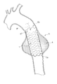
- FIG. 3 is a schematic diagram illustrating an example of a method for using the stent graft 1 at the time of treatment
- FIG. 4 is a schematic diagram illustrating an example of an indwelling mode of the stent graft 1 at the time of this treatment.
- the artery 9 thoracic aorta
- the aneurysm in the artery 9 to be treated is shown as an aneurysm A.
- a predetermined delivery device (not shown) is used to open an opening h formed by incising a part of the artery 9. Then, the reduced diameter stent graft 1 is inserted (see arrow P1). At this time, as shown in FIG. 3, the end portion Ea of the stent graft 1 is inserted as the distal end side, and the end portion Eb (stent non-arrangement region a2 side) is inserted as the proximal end side. Subsequently, using this delivery device, the stent graft 1 end portion Ea is made to reach a site in the artery 9 beyond the site to be treated (near the site where the aneurysm A is formed).
- the stent graft 1 is fixed to the inner wall of the artery 9 as shown in FIG.
- the lumen of the artery 9 in the vicinity of the site where the aneurysm A is formed is expanded and held.
- anastomosis is performed by suturing the proximal end (end Eb side) of the stent graft 1 and the artery 9 (patient blood vessel), and if necessary, an artificial blood vessel different from the stent graft 1 is connected to the anastomosis. You may make it anastomosis with a part.
- the inner circumference of the aneurysm A is covered with the stent graft 1, so that blood flow passes through the stent graft 1, and blood pressure or the like does not act on the aneurysm A. . Therefore, the enlargement of the diameter of the aneurysm A and the rupture of the blood vessel can be prevented, and the blood flow in the aneurysm A is also maintained.
- descending aortic suture (peripheral side anastomosis) is substituted by fixation by the stent graft 1. That is, in this OSG method, since the anastomosis between the distal end side (end Ea side) of the stent graft 1 and the descending aorta is omitted, the anastomosis operation is simplified.
- this OSG method has an advantage that the grafting range of the artificial blood vessel can be set in a wide range, and a surgical treatment of a nearby complication can be performed.
- the stent graft applied to the OSG method is not introduced from the buttocks as in the conventional treatment method described above, it is not necessary to pass through a thin blood vessel, and the outer diameter has a certain degree even in a reduced diameter state. It can be large (thick).
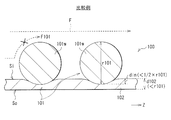
- FIG. 5 is a schematic cross-sectional view of a configuration example of a stent graft (stent graft 100) according to a comparative example.
- stent graft 100 of this comparative example the size relationship between the sizes of the stent 11 and the graft 12 in the stent graft 1 of the present embodiment shown in FIGS. 1 and 2 is changed (the stent 101 and the graft 102 are provided instead).
- other configurations are basically the same.
- the thickness d102 of the graft 102 is smaller than the diameter r101 of the wire 101w in the stent 101 (d102 ⁇ r101). That is, the graft 102 has a structure that is as thin as possible. This is because the stent graft 100 is applied to the conventional treatment method described above.
- the thickness d102 of the graft 102 in the stent graft 100 is set to be as small (thin) as possible.
- the thickness d102 of the graft 102 is about 0.05 to 0.15 mm (eg, 0.10 mm), and the diameter r101 of the wire 101w is about 0.20 mm to 0.50 mm (eg, 0.45 mm). is there.
- the stent graft 100 of this comparative example is applied to, for example, the OSG method
- the following problems may occur. That is, when treating an arterial dissection (aneurysm) using this OSG method, if the thickness d102 of the graft 102 is small (d102 ⁇ r101) as described above, the strength of the graft 102 is insufficient. When the end portion of the stent graft 100 is sutured, the graft 102 may tear and the anastomosis may not be successful. Further, for example, blood leakage from the graft 102 increases, and there is a possibility that arterial dissection or the like cannot be sufficiently treated.
- the thickness d102 of the graft 102 is small, blood leakage from a needle hole formed when the graft 102 is anastomosed with a patient's blood vessel or an artificial blood vessel increases, so that an aneurysm or a pseudo space for arterial dissection is obtained. There is a risk that the blood flow to the body is insufficiently blocked, and a sufficient therapeutic effect cannot be obtained. Therefore, in the stent graft 100 of this comparative example, convenience is impaired in the treatment of arterial dissection or the like using the OSG method, for example.
- the thickness d12 of the graft 12 is larger than the diameter r11 of the wire 11w in the stent 11 (d12> r11). That is, the graft 12 has a thicker structure than the graft 102 according to the comparative example shown in FIG.
- the stent graft 1 for example, in the treatment of arterial dissection using the OSG method described above, there is less risk of the graft 12 tearing when the end Eb is sutured, or from the graft 12 or the above-described needle hole. Blood leakage may be suppressed.
- the graft 12 is arranged so as to cover at least the outer peripheral side of the stent 11, and at least a half of the diameter r11 of the wire 11 w of the stent 11 is
- the graft 12 is embedded on the inner peripheral surface Si side. That is, as shown in FIG. 2, it is set to satisfy the embedding length din ⁇ ⁇ (1/2) ⁇ r11 ⁇ .
- the periphery of the stent 11 is easily wrapped in the graft 12.
- the inner peripheral side of the stent 11 is less likely to protrude from the inner peripheral surface Si of the graft 12, and the blood flow in the stent graft 1 is less likely to be obstructed (see, for example, the blood flow F shown in FIG. 2).
- the stent graft 100 of the comparative example described above as shown in FIG. 5, since the implantation length din ⁇ (1/2) ⁇ r101 ⁇ , it is as follows.
- the inner peripheral side of the stent 101 easily protrudes from the inner peripheral surface Si of the graft 102, and blood flow in the stent graft 100 is likely to be hindered (for example, the blood flow F101 and the x (cross) mark shown in FIG. reference).
- the force applied from the stent 11 is easily dispersed in the thick graft 12 (the buffering effect of the force in the graft 12 is increased), and the inside of the blood vessel is prevented from being damaged by the outer peripheral side of the stent 11.
- the blood vessel wall of the lesion is extremely fragile and is very easily broken, it is important to be able to prevent the inside of the blood vessel from being damaged like the stent graft 1. It can be said.
- the liquid retention H (So) on the outer peripheral surface So side of the graft 12 is higher than the liquid retention H (Si) on the inner peripheral surface Si side of the graft 12. (H (So)> H (Si)).
- the liquid permeability on the outer peripheral surface So side of the graft 12 is larger than the liquid permeability on the inner peripheral surface Si side of the graft 12.
- thrombus is generally generated because blood flows smoothly on the surface.
- a knitted fabric with a dense knitting method or a graft having a low liquid retention property such as a graft made of a film having a low liquid permeability
- thrombus is generally generated because blood flows smoothly on the surface.
- drawbacks in that the anastomosis between the patient's blood vessel and the artificial blood vessel is difficult, and it is difficult to become familiar with surrounding tissues (low adhesion).
- the liquid retaining property is high on the outer peripheral surface So side of the graft 12, and the liquid retaining property is low on the inner peripheral surface Si side of the graft 12. Therefore, it is possible to enjoy the advantages of the two types of structures described above. That is, the stent graft 1 facilitates anastomosis between the graft 12 and the patient's blood vessel or artificial blood vessel, and improves the adhesion between the graft 12 and the inner peripheral surface of the blood vessel (familiarity with surrounding tissues). In addition, thrombi are less likely to occur on the inner peripheral surface Si side of the graft 12.
- the graft 12 has a thicker structure than before (the thickness d12 of the graft 12 is larger than the diameter r11 of the wire 11w of the stent 11). It can be made to show a good liquid retention and liquid permeability. That is, because the graft 12 has a thick structure, the structure on the outer peripheral surface So side and the inner peripheral surface Si side of the graft 12 is made different as described above (for example, the voids in the porous structure of the graft 12). It can be said that a two-layer structure can be realized at different rates.
- the stent 11 is arranged in a partial region (stent placement region a1) along the axial direction of the graft 12. This facilitates anastomosis between the end of the stent graft 1 (the end Eb in this example) and the patient's blood vessel or artificial blood vessel using the stent non-arranged region a2 in the graft 12.
- the thickness d12 of the graft 12 is larger than the diameter r11 of the wire 11w in the stent 11, for example, the following is obtained. That is, for example, in the treatment of arterial dissection using the OSG method, the risk of tearing of the graft 12 is reduced, or leakage of blood from the graft 12 or the aforementioned needle hole is reduced to sufficiently treat arterial dissection or the like. You will be able to Therefore, convenience during treatment can be improved.
- FIG. 6 schematically illustrates a configuration example of a stent graft (stent graft 1 ⁇ / b> A) according to Modification 1 in a cross-sectional view.
- This stent graft 1A corresponds to the stent graft 1 shown in FIGS. 1 and 2 in which the covering mode of the stent 11 by the graft 12 is changed, and other configurations are basically the same.
- the graft 12 is arranged so as to cover the outer peripheral side of the stent 11 (wire material 11 w).
- FIG. 7 is a perspective view schematically showing a schematic configuration example of a stent graft (stent graft 1B) according to Modification 2.
- This stent graft 1B corresponds to the stent graft 1 shown in FIG. 1 and FIG. 2 in which the arrangement region of the stent 11 is changed, and other configurations are basically the same.
- the stent 11 is arranged in a partial region along the axial direction of the graft 12.
- the stent graft 1 has a stent placement area a1 and a stent non-placement area a2 along the axial direction thereof.
- the stent 11 is disposed in the entire region along the axial direction of the graft 12, as shown in FIG.
- the stent graft 1B has only the stent placement region a1 along the axial direction, and does not have the stent non-placement region a2. That is, the stent placement region a1 extends from one end Eb to the other end Eb in the stent graft 1B.
- the shape, arrangement position, size, number, material, and the like of each member described in the above embodiments are not limited, and other shapes, arrangement positions, sizes, numbers, materials, and the like may be used.
- the graft 12 may cover only the inner peripheral side of the stent 11.
- the arrangement shape (braiding pattern) of the wire 11w in the stent 11 is not limited to that described in the above embodiment, and may be other arrangement shapes.
- the embedded length din of the wire 11w in the stent 11 may be less than half of the diameter r11 of the wire 11w, that is, din ⁇ (1/2) ⁇ r11 ⁇ .
- the diameters r11 of the wires 11w may be different from each other. In that case, at least one wire of the plurality of wires 11w is used.
- the diameter r11 of 11w should just satisfy
- the case where only one stent 11 is arranged in the stent graft has been described as an example. However, the present invention is not limited to this, and two or more stents 11 are individually provided in the stent graft. It may be arranged (for example, separated from each other along the axial direction).
- the liquid retention (and liquid permeability) on the outer peripheral surface So side of the graft 12 is greater than the liquid retention (and liquid permeability) on the inner peripheral surface Si side of the graft 12.
- the present invention is not limited to this. That is, in some cases, on the contrary, the liquid retention (and liquid permeability) on the outer peripheral surface So side of the graft 12 is equal to or lower than the liquid retention (and liquid permeability) on the inner peripheral surface Si side of the graft 12. You may make it.
Landscapes
- Health & Medical Sciences (AREA)
- Gastroenterology & Hepatology (AREA)
- Pulmonology (AREA)
- Cardiology (AREA)
- Oral & Maxillofacial Surgery (AREA)
- Transplantation (AREA)
- Engineering & Computer Science (AREA)
- Biomedical Technology (AREA)
- Heart & Thoracic Surgery (AREA)
- Vascular Medicine (AREA)
- Life Sciences & Earth Sciences (AREA)
- Animal Behavior & Ethology (AREA)
- General Health & Medical Sciences (AREA)
- Public Health (AREA)
- Veterinary Medicine (AREA)
- Prostheses (AREA)
Priority Applications (4)
| Application Number | Priority Date | Filing Date | Title |
|---|---|---|---|
| KR1020207016995A KR20200072567A (ko) | 2015-07-23 | 2016-02-03 | 스텐트 그래프트 |
| CN201680017005.2A CN107427356A (zh) | 2015-07-23 | 2016-02-03 | 覆膜支架 |
| KR1020177026795A KR20170120657A (ko) | 2015-07-23 | 2016-02-03 | 스텐트 그래프트 |
| EP16827451.2A EP3326581B1 (en) | 2015-07-23 | 2016-02-03 | Stent graft |
Applications Claiming Priority (2)
| Application Number | Priority Date | Filing Date | Title |
|---|---|---|---|
| JP2015145831A JP6200465B2 (ja) | 2015-07-23 | 2015-07-23 | ステントグラフト |
| JP2015-145831 | 2015-07-23 |
Publications (1)
| Publication Number | Publication Date |
|---|---|
| WO2017013885A1 true WO2017013885A1 (ja) | 2017-01-26 |
Family
ID=57834391
Family Applications (1)
| Application Number | Title | Priority Date | Filing Date |
|---|---|---|---|
| PCT/JP2016/053172 Ceased WO2017013885A1 (ja) | 2015-07-23 | 2016-02-03 | ステントグラフト |
Country Status (6)
| Country | Link |
|---|---|
| EP (1) | EP3326581B1 (enExample) |
| JP (1) | JP6200465B2 (enExample) |
| KR (2) | KR20200072567A (enExample) |
| CN (1) | CN107427356A (enExample) |
| TW (1) | TWI601519B (enExample) |
| WO (1) | WO2017013885A1 (enExample) |
Cited By (1)
| Publication number | Priority date | Publication date | Assignee | Title |
|---|---|---|---|---|
| WO2018087947A1 (ja) * | 2016-11-11 | 2018-05-17 | 日本ライフライン株式会社 | 治療装置 |
Families Citing this family (3)
| Publication number | Priority date | Publication date | Assignee | Title |
|---|---|---|---|---|
| CN111225637A (zh) * | 2017-11-06 | 2020-06-02 | Ea制药株式会社 | 支架以及包括该支架的医疗设备 |
| JP6698262B2 (ja) | 2018-03-09 | 2020-05-27 | 日本ライフライン株式会社 | 大動脈治療装置 |
| WO2023233374A1 (en) * | 2022-06-03 | 2023-12-07 | Medibrane Ltd | Stent assemblies and method of manufacturing |
Citations (3)
| Publication number | Priority date | Publication date | Assignee | Title |
|---|---|---|---|---|
| US20050240261A1 (en) * | 2004-04-23 | 2005-10-27 | Scimed Life Systems, Inc. | Composite medical textile material and implantable devices made therefrom |
| JP2008513118A (ja) * | 2004-09-15 | 2008-05-01 | ボストン サイエンティフィック リミテッド | 弾性放射線不透過性接着剤複合材料及びプロテーゼ |
| JP2015501173A (ja) * | 2011-10-07 | 2015-01-15 | ダブリュ.エル.ゴア アンド アソシエイツ,インコーポレイティドW.L. Gore & Associates, Incorporated | 破裂可能でかつ再シール可能なグラフト |
Family Cites Families (13)
| Publication number | Priority date | Publication date | Assignee | Title |
|---|---|---|---|---|
| DE69518337T2 (de) * | 1995-03-10 | 2001-02-01 | Impra Inc., Tempe | Endoluminal eingekapselter stent und herstellverfahren |
| US6156064A (en) * | 1998-08-14 | 2000-12-05 | Schneider (Usa) Inc | Stent-graft-membrane and method of making the same |
| WO2001015633A1 (en) * | 1999-09-01 | 2001-03-08 | Scimed Life Systems, Inc. | Tubular stent-graft composite device and method of manufacture |
| KR20050091040A (ko) * | 2002-12-30 | 2005-09-14 | 안지오테크 인터내셔날 아게 | 실크 함유 스텐트 이식편 |
| US7763063B2 (en) | 2003-09-03 | 2010-07-27 | Bolton Medical, Inc. | Self-aligning stent graft delivery system, kit, and method |
| JP2008540022A (ja) * | 2005-05-17 | 2008-11-20 | ナイキャスト リミテッド | 植込み可能な荷電性医療装置 |
| JP2008099995A (ja) | 2006-10-20 | 2008-05-01 | Guroobu Kk | ステント及びステントグラフト |
| US20080208325A1 (en) * | 2007-02-27 | 2008-08-28 | Boston Scientific Scimed, Inc. | Medical articles for long term implantation |
| CN102430157B (zh) * | 2011-11-29 | 2013-11-27 | 武汉纺织大学 | 一种内覆膜的医用支架及其制备方法 |
| CN202740157U (zh) * | 2012-08-07 | 2013-02-20 | 湖南瑞康通科技发展有限公司 | 脑动脉瘤支架系统 |
| JP6433897B2 (ja) * | 2012-08-15 | 2018-12-05 | フロウ・フォワード・メディカル・インコーポレイテッドFlow Forward Medical, Inc. | 血液ポンプシステムおよび方法 |
| CN104586537B (zh) * | 2013-10-31 | 2017-05-10 | 微创心脉医疗科技(上海)有限公司 | 一种覆膜支架 |
| CN104758086B (zh) * | 2015-04-20 | 2016-08-17 | 湖南埃普特医疗器械有限公司 | 脑动脉瘤腔内血管重建装置 |
-
2015
- 2015-07-23 JP JP2015145831A patent/JP6200465B2/ja active Active
-
2016
- 2016-02-03 WO PCT/JP2016/053172 patent/WO2017013885A1/ja not_active Ceased
- 2016-02-03 KR KR1020207016995A patent/KR20200072567A/ko not_active Ceased
- 2016-02-03 KR KR1020177026795A patent/KR20170120657A/ko not_active Ceased
- 2016-02-03 EP EP16827451.2A patent/EP3326581B1/en active Active
- 2016-02-03 CN CN201680017005.2A patent/CN107427356A/zh active Pending
- 2016-06-29 TW TW105120506A patent/TWI601519B/zh not_active IP Right Cessation
Patent Citations (3)
| Publication number | Priority date | Publication date | Assignee | Title |
|---|---|---|---|---|
| US20050240261A1 (en) * | 2004-04-23 | 2005-10-27 | Scimed Life Systems, Inc. | Composite medical textile material and implantable devices made therefrom |
| JP2008513118A (ja) * | 2004-09-15 | 2008-05-01 | ボストン サイエンティフィック リミテッド | 弾性放射線不透過性接着剤複合材料及びプロテーゼ |
| JP2015501173A (ja) * | 2011-10-07 | 2015-01-15 | ダブリュ.エル.ゴア アンド アソシエイツ,インコーポレイティドW.L. Gore & Associates, Incorporated | 破裂可能でかつ再シール可能なグラフト |
Non-Patent Citations (1)
| Title |
|---|
| See also references of EP3326581A4 * |
Cited By (1)
| Publication number | Priority date | Publication date | Assignee | Title |
|---|---|---|---|---|
| WO2018087947A1 (ja) * | 2016-11-11 | 2018-05-17 | 日本ライフライン株式会社 | 治療装置 |
Also Published As
| Publication number | Publication date |
|---|---|
| EP3326581A1 (en) | 2018-05-30 |
| TWI601519B (zh) | 2017-10-11 |
| KR20170120657A (ko) | 2017-10-31 |
| JP6200465B2 (ja) | 2017-09-20 |
| EP3326581A4 (en) | 2019-03-13 |
| TW201703739A (zh) | 2017-02-01 |
| JP2017023464A (ja) | 2017-02-02 |
| CN107427356A (zh) | 2017-12-01 |
| KR20200072567A (ko) | 2020-06-22 |
| EP3326581B1 (en) | 2022-01-19 |
Similar Documents
| Publication | Publication Date | Title |
|---|---|---|
| JP5201631B2 (ja) | 体腔用医療機器 | |
| JP4571498B2 (ja) | 開口形成可能な医療装置 | |
| JP6200465B2 (ja) | ステントグラフト | |
| JP7277988B2 (ja) | 開窓用部分を有するステントグラフト | |
| KR102888322B1 (ko) | 개창용 부분을 가지는 스텐트 그라프트 | |
| JP6676424B2 (ja) | 治療装置 | |
| JP6564757B2 (ja) | 治療装置 | |
| JP6960544B2 (ja) | 治療装置 | |
| JP7549147B2 (ja) | 治療装置 | |
| JP7532001B2 (ja) | 治療装置 | |
| JP6850242B2 (ja) | ステントおよび医療機器 | |
| TW202011909A (zh) | 支架和支架移植物 | |
| JPWO2020059101A1 (ja) | ステントおよび医療機器 |
Legal Events
| Date | Code | Title | Description |
|---|---|---|---|
| 121 | Ep: the epo has been informed by wipo that ep was designated in this application |
Ref document number: 16827451 Country of ref document: EP Kind code of ref document: A1 |
|
| ENP | Entry into the national phase |
Ref document number: 20177026795 Country of ref document: KR Kind code of ref document: A |
|
| NENP | Non-entry into the national phase |
Ref country code: DE |