WO2017010483A1 - 飛散防止フィルム、飛散防止フィルム付き3次元曲面ガラス - Google Patents
飛散防止フィルム、飛散防止フィルム付き3次元曲面ガラス Download PDFInfo
- Publication number
- WO2017010483A1 WO2017010483A1 PCT/JP2016/070571 JP2016070571W WO2017010483A1 WO 2017010483 A1 WO2017010483 A1 WO 2017010483A1 JP 2016070571 W JP2016070571 W JP 2016070571W WO 2017010483 A1 WO2017010483 A1 WO 2017010483A1
- Authority
- WO
- WIPO (PCT)
- Prior art keywords
- base material
- adhesive layer
- film
- glass
- scattering
- Prior art date
- Legal status (The legal status is an assumption and is not a legal conclusion. Google has not performed a legal analysis and makes no representation as to the accuracy of the status listed.)
- Ceased
Links
Images




Classifications
-
- B—PERFORMING OPERATIONS; TRANSPORTING
- B32—LAYERED PRODUCTS
- B32B—LAYERED PRODUCTS, i.e. PRODUCTS BUILT-UP OF STRATA OF FLAT OR NON-FLAT, e.g. CELLULAR OR HONEYCOMB, FORM
- B32B27/00—Layered products comprising a layer of synthetic resin
-
- C—CHEMISTRY; METALLURGY
- C03—GLASS; MINERAL OR SLAG WOOL
- C03C—CHEMICAL COMPOSITION OF GLASSES, GLAZES OR VITREOUS ENAMELS; SURFACE TREATMENT OF GLASS; SURFACE TREATMENT OF FIBRES OR FILAMENTS MADE FROM GLASS, MINERALS OR SLAGS; JOINING GLASS TO GLASS OR OTHER MATERIALS
- C03C17/00—Surface treatment of glass, not in the form of fibres or filaments, by coating
- C03C17/34—Surface treatment of glass, not in the form of fibres or filaments, by coating with at least two coatings having different compositions
-
- C—CHEMISTRY; METALLURGY
- C09—DYES; PAINTS; POLISHES; NATURAL RESINS; ADHESIVES; COMPOSITIONS NOT OTHERWISE PROVIDED FOR; APPLICATIONS OF MATERIALS NOT OTHERWISE PROVIDED FOR
- C09J—ADHESIVES; NON-MECHANICAL ASPECTS OF ADHESIVE PROCESSES IN GENERAL; ADHESIVE PROCESSES NOT PROVIDED FOR ELSEWHERE; USE OF MATERIALS AS ADHESIVES
- C09J7/00—Adhesives in the form of films or foils
- C09J7/20—Adhesives in the form of films or foils characterised by their carriers
Definitions
- the present invention relates to an anti-scattering film attached to a sunroof glass or the like of an automobile and a three-dimensional curved glass with an anti-scattering film.
- Patent Document 1 proposes an anti-scattering film in which at least two layers are laminated in the thickness direction and tear strength, Young's modulus and the like are defined to predetermined values.
- Patent Document 2 proposes a scattering prevention film in which the peeling force of an adhesive layer disposed between substrates is adjusted to a predetermined value.
- small and hard flying objects such as pebbles collide with the glass to which the above-mentioned scattering prevention film is attached, even if the glass fragments can be prevented from scattering, the flying object itself has a scattering prevention film. There is a possibility of penetration.
- small and hard flying objects such as pebbles may be referred to as “small flying objects”.
- glass plates used as window materials for buildings are usually flat glass, whereas glass plates used as window materials for automobile sunroofs, etc. are bent three-dimensionally along the shape of the car body. It is often a three-dimensional curved glass.
- the scattering prevention film is usually bonded to the glass plate, which is the window material of the automobile, on the inner side of the automobile, that is, on the concave surface of the curved glass. Therefore, when bonding a scattering prevention film to the glass plate which is a window material of a motor vehicle, there exists a problem that air will enter between a glass plate and a scattering prevention film, and an external appearance will be impaired.
- three-dimensional curved glass that is used as a window material for an automobile sunroof, etc., and is three-dimensionally bent along the vehicle body shape of the automobile is a cross section observed from at least two predetermined directions in plan view.
- the cross section from the X-ray extended in the X direction is a curved surface, and intersects the X direction on the surface of the glass plate.
- the section from the Y line extended in the Y direction is a curved surface. Therefore, for example, in the case of the sunroof glass 1 of an automobile as shown in FIG. 7A, as shown in FIG.
- FIG. 7B the X-ray cross section of FIG. As shown in FIG. 7C, it means that the Y-line cross section of FIG. 7A is a curved surface.
- the X-ray and the Y-line are orthogonal to each other, but the directions of the X-ray and the Y-line are not limited to being orthogonal.
- An object of the present invention is to prevent penetration of a small flying object that has collided, and when it is bonded to a three-dimensional curved glass that is bent three-dimensionally such as a sunroof of an automobile, air is interposed between the three-dimensional curved glass. It is providing the scattering prevention film which can suppress that it enters.
- -1st invention is a scattering prevention film which can be affixed on a transparent member with the said adhesion layer arrange
- the scattering prevention film is a scattering prevention film having a layer thickness of 100 to 300 ⁇ m and a thickness ratio of the base material to the adhesive layer of 100: 10 to 100: 40. .
- -2nd invention is the scattering prevention film by which the 1st base material (11) and the 1st adhesion layer (21) which have optical transparency were laminated, and the total thickness of the scattering prevention film is 100 micrometers or more and 300 micrometers
- the scattering prevention film is characterized in that the thickness ratio between the first base material (11) and the first adhesive layer (21) is 100: 10 or more and 100: 40 or less.
- the third invention is the anti-scattering film of the second invention, wherein the first adhesive layer (21) has a peel strength of 20 N / sec against a glass plate according to a 180 degree peel test specified in JIS K6854-2. It is a scattering prevention film characterized by being 25 mm width or more and 30 N / 25 mm width or less.
- -4th invention is a scattering prevention film of 2nd invention or 3rd invention, Comprising: It is light on the surface on the opposite side to the said 1st base material (11) of the said 1st adhesion layer (21).
- a second pressure-sensitive adhesive layer (12) having light permeability on the surface of the second base material (12) opposite the first pressure-sensitive adhesive layer (21). 22), and the first pressure-sensitive adhesive layer (21) has a peel strength against the glass plate according to the 180-degree peel test specified in JIS K6854-2 as specified in JIS K6854-2 of the second pressure-sensitive adhesive layer (22).
- An anti-scattering film having a peel strength of not more than a glass plate according to a 180 degree peel test.
- -5th invention is a scattering prevention film of any invention from 2nd invention to 4th invention, Comprising: It is opposite to said 1st adhesion layer (21) of said 1st base material (11) It is a scattering prevention film characterized by having a hard-coat layer (31) whose surface hardness is higher than the said 1st base material (11) in the side surface side.
- -6th invention is a scattering prevention film of any invention from 2nd invention to 5th invention, Comprising: It is opposite to the said 1st base material (11) of the said 1st adhesion layer (21) An anti-scattering film comprising a separator film on the side surface.
- a three-dimensional curved glass with an anti-scattering film characterized by comprising a two-dimensional curved glass.
- the present invention it is possible to suppress penetration of a small flying object that has collided, and when it is bonded to a three-dimensional curved glass that is bent three-dimensionally such as a sunroof of an automobile, air is interposed between the three-dimensional curved glass. It is possible to provide a scattering prevention film that can easily suppress the entry of water.
- the anti-scattering film according to the present invention is applied to a sunroof glass of an automobile.
- each figure shown below including FIG. 1 is the figure shown typically, and the magnitude
- the numerical values such as the dimensions of the respective members and the material names described in the present specification are examples of the embodiment, and are not limited thereto, and may be appropriately selected and used.
- the names of members are appropriately simplified and described, for example, “scattering prevention film” is referred to as “film”, and reference numerals are appropriately omitted.
- the base material and the adhesive layer used for the anti-scattering film may be referred to as a first base material, a second base material, a first adhesive layer, and a second adhesive layer.
- FIG. 1 is a cross-sectional view of a sunroof glass 1 in the first embodiment.
- the sunroof glass 1 of 1st Embodiment is equipped with the glass main body 2 and the scattering prevention film 10 as a transparent member.
- the glass body 2 is a general float glass used as a sunroof glass for automobiles, and the material is not particularly limited.
- the glass body 2 may be tempered glass, for example.
- the scattering prevention film 10 includes a first base material 11 and a first adhesive layer 21.
- the 1st base material 11 and the 1st adhesion layer 21 are members which have optical transparency.
- “having light transmissivity” means that, unless otherwise specified, when the anti-scattering film of the present invention is used for a three-dimensional curved glass such as a sunroof of an automobile, it does not hinder the visibility from inside the vehicle. It has a light-transmitting property. Therefore, “having light transmittance” includes colorlessness and a color that does not hinder visibility, is not defined by strict light transmittance, and is used for an automobile sunroof or the like that uses the anti-scattering film of the present invention. It can adjust suitably according to the light transmittance of three-dimensional curved surface glass, etc.
- a cellulose resin such as triacetyl cellulose (TAC), an acrylic resin such as polymethyl methacrylate (PMMA), and a polyester resin such as polyethylene terephthalate (PET).
- TAC triacetyl cellulose
- PMMA acrylic resin
- PET polyester resin
- a polyolefin resin such as polypropylene (PP), a vinyl resin such as polyvinyl chloride (PVC), and a transparent resin film such as polycarbonate (PC) can be applied.
- the thickness of the first base material 11 is desirably 200 ⁇ m or more, but can be set to about 100 ⁇ m by appropriately adjusting the peeling force of the first adhesive layer 21 as shown in Examples described later. .
- the preferable rigidity of the 1st base material 11 is the range of 700 MPa or more and 3000 MPa or less in Young's modulus.
- a material having transparency and light resistance can be applied to the first adhesive layer 21 on the condition that the necessary interlayer adhesive strength can be maintained between the glass body 2 and the first base material 11.
- an adhesive material having a peeling force against a glass plate by a 180 degree peeling test defined in JIS K6854-2, a so-called peeling strength within a range of 20 N / 25 mm width to 30 N / 25 mm width is applied. Is done. Specifically, for example, it is composed of a structural unit derived from a methacrylic acid ester, and an acrylic resin derived from an acrylate ester and / or another unsaturated monomer can be applied as necessary.
- examples of the methacrylic acid ester include alkyl esters of methacrylic acid such as methyl methacrylate, ethyl methacrylate, propyl methacrylate, butyl methacrylate, and pentyl methacrylate.
- examples of the acrylate ester include methyl acrylate, ethyl acrylate, propyl acrylate, butyl acrylate, and pentyl acrylate.
- the total thickness including the first base material 11 and the first adhesive layer 21 is set in a range of 100 ⁇ m or more and 300 ⁇ m or less.
- the total thickness of the anti-scattering film 10 is less than 100 ⁇ m, the strength against impact may be insufficient and penetration of small flying objects may not be prevented.
- the total thickness of the anti-scattering film 10 exceeds 300 ⁇ m, for example, followability to a three-dimensional curved surface such as a sunroof of an automobile is deteriorated, so that workability when being attached to the glass body 2 is deteriorated.
- the layer thickness of the scattering prevention film 10 in the range of 100 ⁇ m or more and 300 ⁇ m or less.
- the anti-scattering film 10A has a layer structure including the first base material 11, the first adhesive layer 21, the second base material 12, and the second adhesive layer 22 as in the second embodiment to be described later. Is the same.
- total thickness refers to the total thickness of the anti-scattering film 10, for example, the distance indicated by the symbol t in FIGS. 1 and 2.
- the thickness ratio of the 1st base material 11 and the 1st adhesion layer 21 is set to the range of 100: 10 or more and 100: 40 or less.
- the thickness of the first adhesive layer 21 can be set to a predetermined value or more with respect to the thickness of the first base material 11. . Therefore, for example, when it is bonded to a three-dimensional curved glass that is bent three-dimensionally such as a sunroof of an automobile, it is possible to easily suppress air from entering between the three-dimensional curved glass.
- the thickness ratio of the 1st base material 11 and the 1st adhesion layer 21 is less than 100: 10, ie, the thickness of the 1st adhesion layer 21 when the 1st substrate 11 thickness is set to 100 is less than 10. Then, since the effect of the first adhesive layer 21 wrapping the glass fragments becomes poor, the small flying objects are easily penetrated by the piercing of the first base material 11 by the glass fragments. On the other hand, when the thickness ratio of the first base material 11 and the first adhesive layer 21 exceeds 100: 40, that is, when the thickness of the first adhesive layer 21 when the thickness of the first base material 11 is 100, the thickness ratio exceeds 40. The flatness of the anti-scattering film 10 is deteriorated.
- the total thickness of the anti-scattering film 10 is in the range of 100 ⁇ m or more and 300 ⁇ m or less, and the thickness ratio between the first base material 11 and the first adhesive layer 21 is 100: 10 or more and 100: 40 or less. By setting the range, it is possible to improve the penetration resistance of colliding small flying objects.
- the first adhesive layer 21 is a strong adhesive layer in which the peel force to the glass plate by the 180 degree peel test specified in JIS K6854-2 is in the range of 20 N / 25 mm width to 30 N / 25 mm width, More glass fragments broken by the impact of flying objects can be wrapped. According to this, since the stab of the 1st base material 11 by a glass fragment is suppressed, the penetration resistance of the small flying object which collided can be improved more.
- the scattering prevention film 10 may have a separator film on the surface side of the first adhesive layer 21 opposite to the first base material 11.
- a separator film may be attached to the outermost layer.
- the separator film is a film for protecting the adhesive surface of the first adhesive layer 21 in the storage state before the anti-scattering film 10 is attached to the glass body 2.
- the separator film is preferably a member that can be releasably supported on the adhesive surface of the first adhesive layer on the side to be attached to the glass body.
- a resin film such as a polyester resin such as polyethylene terephthalate, polybutylene terephthalate, or polyethylene aphthalate, or a polyolefin resin such as polypropylene or polymethylpentene can be used.
- the thickness of the separator film can be in the range of 20 ⁇ m or more and 100 ⁇ m or less, for example. When the thickness of the separator film is within the above range, the separator film can be easily peeled off after being attached to the exposed first adhesive layer 21 on the side to be attached to the glass body.
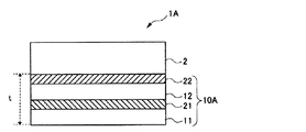
- FIG. 2 is a cross-sectional view of the sunroof glass 1A in the second embodiment.
- members that are functionally equivalent to the members described in the first embodiment are denoted by the same reference numerals as in the first embodiment, and redundant descriptions are omitted as appropriate. The same applies to other embodiments.
- the scattering prevention film 10 ⁇ / b> A includes a first base material 11, a first adhesive layer 21, a second base material 12, and a second adhesive layer 22. In the point, it differs from the scattering prevention film 10 of 1st Embodiment.
- the scattering prevention film 10 ⁇ / b> A of the present embodiment includes the second base material 12 and the second adhesive layer 22 between the first adhesive layer 21 and the glass body 2. That is, in the scattering prevention film 10A of the present embodiment, the first base material 11, the first adhesive layer 21, the second base material 12, and the second adhesive layer 22 are arranged in order from the outermost layer in the thickness direction.
- the same material as the 1st substrate 11 and the 1st adhesion layer 21 of a 1st embodiment is applicable.
- the preferable rigidity of the 2nd base material 12 is the range of 1400 MPa or more and 6000 MPa or less in Young's modulus.
- the layer thickness including the first base material 11, the first adhesive layer 21, the second base material 12, and the second adhesive layer 22 is set in a range of 100 ⁇ m or more and 300 ⁇ m or less.
- the thickness ratio between the total thickness of the first base material 11 and the second base material 12 and the total thickness of the first adhesive layer 21 and the second adhesive layer 22 is 100: 10 or more.
- the range is set to 100: 40 or less.
- the first adhesive layer 21 disposed between the first base material 11 and the second base material 12 is made of glass by a 180 degree peel test specified in JIS K6854-2.
- the peeling force with respect to the plate is set to be equal to or less than the peeling force with respect to the glass plate by the 180 degree peel test specified in JIS K6854-2 of the second adhesive layer 22 disposed on the side in contact with the glass body 2.
- the peeling force of the first adhesive layer 21 and the second adhesive layer 22 is 20N. / 25 mm width or less may be sufficient.
- the peeling force of the first adhesive layer and the second adhesive layer is set to 20 N / 25 mm width or less, and both have good results.
- the peeling force of the first adhesive layer 21 disposed between the first base material 11 and the second base material 12 is disposed on the side in contact with the glass body 2. It is desirable to make it relatively smaller than the peeling force of the second adhesive layer 22. That is, the first adhesive layer 21 is a weak adhesive layer having a relatively low adhesive force, and the second adhesive layer 22 is a strong adhesive layer having a relatively large adhesive force. In such a configuration, the second adhesive layer 22 that is a strong adhesive layer disposed on the glass body 2 side can wrap more glass fragments damaged by the collision of small flying objects.
- the 1st adhesion layer 21 which is the weak adhesion layer arrange
- the first base material 11 can be bent independently of the second base material 12. Therefore, in the 1st base material 11, the impact by the inertial force of a glass piece can be absorbed.
- positioned between the 1st base material 11 and the 2nd base material 12 is made into a strong adhesion layer contrary to the scattering prevention film 10A of this embodiment.
- An anti-scattering film in which the second adhesive layer 22 disposed on the side in contact with the glass body 2 is a weak adhesive layer has also been proposed.
- the film can be easily peeled off from the glass body 2, so that it can be easily replaced by dirt.
- the strength of the adhesive force in the adhesive layer is opposite to that of the anti-scattering film 10A of this embodiment, it is expected that the same effect as this embodiment cannot be expected for penetration resistance to small flying objects. .
- the second adhesive layer 22 disposed on the side in contact with the glass body 2 is a weak adhesive layer
- flexibility of the 1st adhesion layer 21 is impaired when the 1st adhesion layer 21 arrange
- the first base material 11 is reached, it is difficult to bend the first base material 11 independently of the second base material 12. Therefore, in the 1st base material 11, it is thought that it becomes difficult to absorb the impact by the inertial force of a glass piece.
- the scattering prevention film 10 of this embodiment may have a separator film on the surface side of the first adhesive layer 21 opposite to the first base material 11.
- a separator film may be attached to the outermost layer.
- a separator since it can be made to be the same as that of the content described in the term of 1st Embodiment, description here is abbreviate
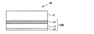
- FIG. 3 is a cross-sectional view of the sunroof glass 1B in the third embodiment.
- the sunroof glass 1B of the present embodiment is hard-coated on the outermost surface layer in the thickness direction of the anti-scattering film 10B, that is, on the surface side opposite to the first adhesive layer 21 of the first base material 11.
- the point which has the layer 31 differs from the sunroof glass 1 of 1st Embodiment.
- the other layer configuration is the same as the sunroof glass 1 of the first embodiment.
- the hard coat layer 31 is a layer for further suppressing the small flying object colliding with the sunroof glass 1B from penetrating the first base material 11 of the anti-scattering film 10B.
- the hard coat layer 31 preferably has a predetermined surface hardness. Specifically, the surface hardness of the first base material is preferably higher than that described above.
- the pencil hardness of JIS K5600-5-4 (1999) on the surface of the protective layer is preferably F or more, Above all, it is preferably H or more.
- the material of the hard coat layer 31 may be any material that is generally used. For example, an ionizing radiation curable resin can be used.
- the ionizing radiation curable resin examples include acrylate-based, oxetane-based, and silicone-based resins.
- an arbitrary material may be added to the hard code layer 31 to add other functions.
- silicone compounds, fluorine compounds, etc. may be added to improve stain resistance
- ions such as PEDOT-PSS, electron conduction types, lithium salt materials, etc.
- a conductive type antistatic agent may be added.
- a fluorine compound or the like may be added to the hard coat layer 31 in order to improve water repellency.
- the thickness of the hard coat layer 31 is set in the range of 2 ⁇ m to 10 ⁇ m.
- the surface hardness of the hard coat layer 31 is desirably set higher than the surface hardness of the first base material 11.
- the glass It is possible to suppress the penetration of the anti-scattering film 10B due to the fragments as much as possible. Therefore, according to the layer configuration of the present embodiment, it is possible to further improve the penetration resistance of glass fragments in the scattering prevention film 10B.
- FIG. 4 is a cross-sectional view of the sunroof glass 1C in the fourth embodiment.
- the sunroof glass 1C of the present embodiment is hard-coated on the outermost layer in the thickness direction of the anti-scattering film 10C, that is, on the surface opposite to the first adhesive layer 21 of the first base material 11.
- the sunroof glass 1A of 2nd Embodiment differs from the sunroof glass 1A of 2nd Embodiment.
- the other layer configuration is the same as the sunroof glass 1A of the second embodiment.
- the penetration resistance of glass fragments in the scattering prevention film 10C can be further improved for the same reason as in the third embodiment.
- the three-dimensional curved glass with an anti-scattering film of the present invention has the above-described anti-scattering film and the three-dimensional curved glass on the side opposite to the first substrate of the anti-scattering film.
- the outermost layer on the side opposite to the first base material of the anti-scattering film may have a three-dimensional curved glass. Accordingly, in FIGS. 1 to 4 described above, the three-dimensional curved glass is arranged at the position where the glass body 2 is arranged.
- the scattering prevention film since it can be the same as that of the content demonstrated by the term of the said "1. scattering prevention film", description here is abbreviate
- the three-dimensional curved glass in the three-dimensional curved glass with the anti-scattering film of the present invention is not particularly limited as long as at least the surface on which the anti-scattering film is attached is a three-dimensionally bent glass plate.
- examples of such three-dimensional curved glass include an automobile sunroof, side window, rear window, and the like, and an automobile sunroof is particularly preferable.
- the three-dimensional curved glass preferably has a predetermined light transmittance from the viewpoint that it is suitable for a sunroof or the like of an automobile.
- the light transmittance of specific 3D curved glass it can adjust suitably according to a specific use, a design, etc., It does not specifically limit.
- the material of the three-dimensional curved glass can be appropriately selected according to the application.
- a material used for a general automobile window material is used. Can do. Therefore, the description about the specific material of 3D curved glass is abbreviate
- the thickness of the three-dimensional curved glass can be appropriately adjusted according to the use of the three-dimensional curved glass of the present invention, and is not particularly limited. For example, when the three-dimensional curved glass is an automobile sunroof or the like, the thickness can be the same as that of a general automobile sunroof or the like, and therefore description thereof is omitted here.
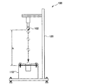
- FIG. 5 is a schematic diagram of the falling ball tester 100 used in the penetration resistance test.
- the falling ball tester 100 includes a test body support portion 110 and a steel ball dropping portion 120.
- the test body support part 110 is a part that holds a test body 101 to be described later horizontally.
- the steel ball dropping unit 120 is a part that holds the steel ball 102 at a predetermined height and drops the steel ball 102 from the position where the steel ball 102 is held toward the test body 101.
- a falling ball testing machine 100 shown in FIG. 5 is configured as a test apparatus that satisfies the conditions of the penetration resistance test defined in the test item (4) of JIS R3212: 1998.
- the scattering prevention films of Examples and Comparative Examples described later were cut into 100 mm ⁇ 100 mm squares and attached to tempered glass (glass body 2) of 100 mm ⁇ 100 mm ⁇ 3 mm (thickness) to obtain a test body 101. It fixed to the test body support part 110 shown in FIG. 5 so that the glass surface of this test body 101 may face up.
- a steel ball 102 having a weight of 227 g and a diameter of about 38 mm was dropped three times from a height of 3.5 m, and whether or not the steel ball 102 penetrates the test body 101 was evaluated.
- the drop of the steel ball 102 with respect to one test body 101 was performed only once. Therefore, in each of the examples and comparative examples, three identical test bodies 101 were prepared and a penetration resistance test was performed. In this test, the test was performed based on conditions and procedures according to the penetration resistance test defined in the test item (4) of JIS R3212: 1998. However, in this test, as shown in FIG. 5, the height h from the test body 101 to the lower surface of the steel ball 102 was set to 3.5 m. In this test, as a reference example, the penetration resistance was also tested when a steel ball 102 having a weight of 400 g was dropped under the same conditions.
- FIG. 6 is a diagram for explaining the results of the penetration resistance test. The items of the layer configuration in FIG. 6 will be described.
- “Base material A” is the first base material 11 disposed on the outermost layer of the scattering prevention film.
- the “adhesion a” is a first adhesive layer 21 disposed between the first base material 11 and the glass body 2 or a first adhesive layer disposed between the first base material 11 and the second base material 12. 21.
- Base material B is a second base material 12 disposed between the first base material 11 and the glass body 2.
- Adhesion b is the second adhesive layer 22 disposed on the side in contact with the glass body 2.
- “HC” is the hard coat layer 31.
- peel strength of the adhesive a and the adhesive b is described as “peel strength”.
- Example 1 Example 3, and Example 5 are test bodies having the same layer configuration, layer thickness, thickness ratio, and peel strength as those of the second embodiment.
- Example 2 and Example 4 are test bodies having the same layer configuration, layer thickness, thickness ratio, and peel strength as in the first embodiment.
- Example 6 is a test body having the same layer configuration, layer thickness, thickness ratio, and peel strength as the fourth embodiment.
- Comparative Example 1 has the same layer configuration as that of the first embodiment, but the point that the thickness ratio of the base material A and the adhesive a is out of the range of 100: 10 or more and 100: 40 or less is Example 2 and the implementation. Different from Example 4.
- the thickness ratio of the thickness of the base material A and the base material B and the thickness of the adhesion a and the adhesion b is 100: 10 or more and 100: 40 or less. This is different from the first, third, and fifth embodiments in that it is out of the range.
- Example 2 is a test body in which the thickness of the base material A is 188 ⁇ m in the configuration of the first embodiment. When the base material A was thickened, it was confirmed that good results were obtained even when the adhesive a was a weak adhesive layer having a peel strength of 11 N / 25 mm width.
- Example 4 is a test body in which the thickness of the base material A is 100 ⁇ m in the same configuration of the first embodiment.
- Example 5 and Example 6 as shown in the reference example of FIG. 6, even when the weight of the steel ball 102 was 400 g, good results could be obtained.
- the 2nd adhesion layer 22 which is a strong adhesion layer, in addition to being able to wrap more broken glass fragments, when a glass fragment reaches the base material 11, it becomes more flexible. Since the first base material 11 is bent by the first adhesive layer 21 which is an enhanced weak adhesive layer and the impact due to the inertial force of the glass fragments is absorbed, the penetration resistance of the glass fragments in the first substrate 11 is further improved. it is conceivable that.
- Example 6 since the hard-coat layer 31 was arrange
- Example 2 In addition, in this test, penetration resistance was not implemented about the Example of the same layer structure as 3rd Embodiment. However, considering that good results are obtained in the layer configuration of Example 2 that does not include the hard coat layer 31, the test body of Example 2 has a layer configuration that includes the hard coat layer 31. Further, the penetration resistance is expected to be further improved.
- the base material in the scattering prevention film of this invention becomes the 1st base material 11 the surface on the opposite side to the surface bonded together on a glass main body.
- the outermost layer of the side bonded to a glass main body becomes an adhesion layer normally except the case where a scattering prevention film of this invention has a separator film.
- the sunroof of an automobile is not required to have high impact resistance like that of a windshield.
- a small flying object may collide like the windshield, it is necessary to suppress penetration of the small flying object. Therefore, by applying the anti-scattering film according to the present invention to an automobile sunroof glass, it is possible to ensure sufficient penetration resistance against small flying objects without using an expensive laminated glass like a windshield. it can.
- the anti-scattering film according to the present invention can be applied not only to the sunroof glass of an automobile but also to a side window and a rear window of an automobile.
- the scattering prevention film according to the present invention can also be applied to window glass and show windows of ordinary houses and office buildings.
Landscapes
- Chemical & Material Sciences (AREA)
- Organic Chemistry (AREA)
- Life Sciences & Earth Sciences (AREA)
- Engineering & Computer Science (AREA)
- Chemical Kinetics & Catalysis (AREA)
- General Chemical & Material Sciences (AREA)
- Geochemistry & Mineralogy (AREA)
- Materials Engineering (AREA)
- Laminated Bodies (AREA)
- Surface Treatment Of Glass (AREA)
- Adhesive Tapes (AREA)
- Adhesives Or Adhesive Processes (AREA)
Abstract
衝突した小飛来物の貫通を抑制することができる飛散防止フィルムを提供する。 飛散防止フィルム10は、光透過性を有する基材11及び粘着層21が積層され、厚み方向の最表層に配置された粘着層21により透明部材2に貼り付け可能な飛散防止フィルムであって、飛散防止フィルム10は、総厚が100μm以上300μm以下であり、基材11と粘着層21との厚み比が100:10以上100:40以下であることを特徴とする。
Description
本発明は、自動車のサンルーフガラス等に貼り付けられる飛散防止フィルム及び飛散防止フィルム付き3次元曲面ガラスに関する。
飛散防止フィルムは、貼り付けられたガラスが破損した場合でも、その破片の飛散を防止するため、高強度且つフィルムの破れが生じにくい特性が要求される。このような要求に応えるため、例えば特許文献1では、厚み方向に少なくとも2層に積層され、引き裂き強度、ヤング率等を所定の値に規定した飛散防止フィルムが提案されている。また、例えば特許文献2では、基材間に配置された粘着層の剥離力を所定の値に調整した飛散防止フィルムが提案されている。
上述した飛散防止フィルムが貼り付けられたガラスに、小石等の小さくて硬い飛来物が衝突した場合、ガラスの破片が飛散することを防ぐことはできても、当該飛来物自体が飛散防止フィルムを貫通する可能性がある。なお、以下、小石等の小さくて硬い飛来物を、「小飛来物」と称して説明する場合がある。
また、建築物の窓材として用いられるガラス板は、通常、平面ガラスであるのに対し、自動車のサンルーフ等の窓材として用いられるガラス板は、自動車の車体形状に沿って3次元に屈曲した3次元曲面ガラスであることが多い。さらに、自動車の窓材であるガラス板への飛散防止フィルムの貼合は、通常、自動車の車内側、すなわち曲面ガラスの凹面に行われる。そのため、自動車の窓材であるガラス板に飛散防止フィルムを貼合する際、ガラス板と飛散防止フィルムとの間に空気が入ってしまい、外観を損ねてしまうという問題がある。
なお、ここで、自動車のサンルーフ等の窓材として用いられ、自動車の車体形状に沿って3次元に屈曲した「3次元曲面ガラス」とは、平面視上、少なくとも所定の2方向から観察した断面が曲面であるガラスをいう。具体的には、ガラス板を平面視したとき、例えばガラス板の表面において、Xの方向に延伸したX線からの断面が曲面であり、かつ、ガラス板の表面において、上記X方向と交差するY方向に延伸したY線からの断面が曲面であることをいう。したがって、例えば、図7(a)に示すような自動車のサンルーフガラス1の場合には、図7(b)に示すように、図7(a)のX線断面が曲面であり、かつ、図7(c)に示すように、図7(a)のY線断面が曲面であることをいう。図7(a)~図7(c)では、X線およびY線が直交しているが、X線およびY線の方向は直交する場合に限定されない。
本発明の課題は、衝突した小飛来物の貫通を抑制することができ、自動車のサンルーフ等の3次元に屈曲した3次元曲面ガラスに貼合した際に、3次元曲面ガラスとの間に空気が入り込むことを抑制することができる飛散防止フィルムを提供することである。
本発明は、以下のような解決手段により前記課題を解決する。なお、理解を容易にする
ために、本発明の実施形態に対応する符号を付して説明するが、これに限定されない。
・第1の発明は、光透過性を有する基材(11)及び粘着層(21)が積層され、厚み方向の最表層に配置された前記粘着層により透明部材に貼り付け可能な飛散防止フィルムであって、前記飛散防止フィルムは、層厚が100~300μmであり、前記基材と前記粘着層との厚み比が100:10~100:40であることを特徴とする飛散防止フィルムである。
・第2の発明は、光透過性を有する第1基材(11)及び第1粘着層(21)が積層された飛散防止フィルムであって、前記飛散防止フィルムは、総厚が100μm以上300μm以下であり、前記第1基材(11)と前記第1粘着層(21)との厚み比が100:10以上100:40以下であること、を特徴とする飛散防止フィルムである。
・第3の発明は、第2の発明の飛散防止フィルムであって、前記第1粘着層(21)は、JIS K6854-2に規定の180度剥離試験によるガラス板に対する剥離力が、20N/25mm幅以上30N/25mm幅以下であることを特徴とする飛散防止フィルムである。
・第4の発明は、第2の発明又は第3の発明の飛散防止フィルムであって、前記第1粘着層(21)の前記第1基材(11)とは反対側の面に、光透過性を有する第2基材(12)を有し、前記第2基材(12)の前記第1粘着層(21)とは反対側の面に、光透過性を有する第2粘着層(22)を有し、前記第1粘着層(21)は、JIS K6854-2に規定の180度剥離試験によるガラス板に対する剥離力が、前記第2粘着層(22)のJIS K6854-2に規定の180度剥離試験によるガラス板に対する剥離力以下であることを特徴とする飛散防止フィルム。
・第5の発明は、第2の発明から第4の発明までのいずれかの発明の飛散防止フィルムであって、前記第1基材(11)の前記第1粘着層(21)とは反対側の面側に、前記第1基材(11)よりも表面硬度の高いハードコート層(31)を有することを特徴とする飛散防止フィルムである。
・第6の発明は、第2の発明から第5の発明までのいずれかの発明の飛散防止フィルムであって、前記第1粘着層(21)の前記第1基材(11)とは反対側の面側に、セパレータフィルムを有することを特徴とする飛散防止フィルム。
・第7の発明は、第1の発明から第5の発明までのいずれかの発明の飛散防止フィルムと、前記飛散防止フィルムの前記第1基材(11)とは反対側の面側の3次元曲面ガラスとを有することを特徴とする飛散防止フィルム付き3次元曲面ガラス。
ために、本発明の実施形態に対応する符号を付して説明するが、これに限定されない。
・第1の発明は、光透過性を有する基材(11)及び粘着層(21)が積層され、厚み方向の最表層に配置された前記粘着層により透明部材に貼り付け可能な飛散防止フィルムであって、前記飛散防止フィルムは、層厚が100~300μmであり、前記基材と前記粘着層との厚み比が100:10~100:40であることを特徴とする飛散防止フィルムである。
・第2の発明は、光透過性を有する第1基材(11)及び第1粘着層(21)が積層された飛散防止フィルムであって、前記飛散防止フィルムは、総厚が100μm以上300μm以下であり、前記第1基材(11)と前記第1粘着層(21)との厚み比が100:10以上100:40以下であること、を特徴とする飛散防止フィルムである。
・第3の発明は、第2の発明の飛散防止フィルムであって、前記第1粘着層(21)は、JIS K6854-2に規定の180度剥離試験によるガラス板に対する剥離力が、20N/25mm幅以上30N/25mm幅以下であることを特徴とする飛散防止フィルムである。
・第4の発明は、第2の発明又は第3の発明の飛散防止フィルムであって、前記第1粘着層(21)の前記第1基材(11)とは反対側の面に、光透過性を有する第2基材(12)を有し、前記第2基材(12)の前記第1粘着層(21)とは反対側の面に、光透過性を有する第2粘着層(22)を有し、前記第1粘着層(21)は、JIS K6854-2に規定の180度剥離試験によるガラス板に対する剥離力が、前記第2粘着層(22)のJIS K6854-2に規定の180度剥離試験によるガラス板に対する剥離力以下であることを特徴とする飛散防止フィルム。
・第5の発明は、第2の発明から第4の発明までのいずれかの発明の飛散防止フィルムであって、前記第1基材(11)の前記第1粘着層(21)とは反対側の面側に、前記第1基材(11)よりも表面硬度の高いハードコート層(31)を有することを特徴とする飛散防止フィルムである。
・第6の発明は、第2の発明から第5の発明までのいずれかの発明の飛散防止フィルムであって、前記第1粘着層(21)の前記第1基材(11)とは反対側の面側に、セパレータフィルムを有することを特徴とする飛散防止フィルム。
・第7の発明は、第1の発明から第5の発明までのいずれかの発明の飛散防止フィルムと、前記飛散防止フィルムの前記第1基材(11)とは反対側の面側の3次元曲面ガラスとを有することを特徴とする飛散防止フィルム付き3次元曲面ガラス。
本発明によれば、衝突した小飛来物の貫通を抑制することができ、自動車のサンルーフ等の3次元に屈曲した3次元曲面ガラスに貼合した際に、3次元曲面ガラスとの間に空気が入り込むことを容易に抑制することができる飛散防止フィルムを提供することができる。
1.飛散防止フィルム
以下、本発明に係る飛散防止フィルムを、自動車のサンルーフガラスに適用した実施形態について説明する。なお、図1を含め、以下に示す各図は、模式的に示した図であり、各部の大きさ、形状は、理解を容易にするために、適宜誇張している。
また、本明細書中に記載する各部材の寸法等の数値及び材料名等は、実施形態としての一例であり、これに限定されるものではなく、適宜選択して使用してよい。
さらに、以下に説明する実施形態では、例えば、「飛散防止フィルム」を「フィルム」というように、部材の名称を適宜に簡略化して記載し、また符号を適宜に省略する。
さらにまた、本明細書では、飛散防止フィルムに用いられる基材および粘着層を、第1基材、第2基材、第1粘着層および第2粘着層と称して説明する場合がある。
以下、本発明に係る飛散防止フィルムを、自動車のサンルーフガラスに適用した実施形態について説明する。なお、図1を含め、以下に示す各図は、模式的に示した図であり、各部の大きさ、形状は、理解を容易にするために、適宜誇張している。
また、本明細書中に記載する各部材の寸法等の数値及び材料名等は、実施形態としての一例であり、これに限定されるものではなく、適宜選択して使用してよい。
さらに、以下に説明する実施形態では、例えば、「飛散防止フィルム」を「フィルム」というように、部材の名称を適宜に簡略化して記載し、また符号を適宜に省略する。
さらにまた、本明細書では、飛散防止フィルムに用いられる基材および粘着層を、第1基材、第2基材、第1粘着層および第2粘着層と称して説明する場合がある。
(第1実施形態)
図1は、第1実施形態におけるサンルーフガラス1の断面図である。図1及び図2~図4では、粘着層にのみハッチングを付している。
図1に示すように、第1実施形態のサンルーフガラス1は、透明部材としてガラス本体2と、飛散防止フィルム10と、を備える。
図1は、第1実施形態におけるサンルーフガラス1の断面図である。図1及び図2~図4では、粘着層にのみハッチングを付している。
図1に示すように、第1実施形態のサンルーフガラス1は、透明部材としてガラス本体2と、飛散防止フィルム10と、を備える。
ガラス本体2は、自動車のサンルーフ用ガラスとして用いられる一般的なフロートガラス等であり、その材質は特に限定されない。ガラス本体2は、例えば、強化ガラスであってもよい。
飛散防止フィルム10は、第1基材11と、第1粘着層21と、を備える。
第1基材11及び第1粘着層21は、光透過性を有する部材である。ここで、「光透過性を有する」とは、特段の断りがない限り、本発明の飛散防止フィルムを自動車のサンルーフ等の3次元曲面ガラスに用いた際に、車内からの視認を妨げない程度に光透過性を有することをいう。したがって、「光透過性を有する」とは、無色、および視認性を妨げない程度の有色を含み、また厳密な光透過率で定義されず、本発明の飛散防止フィルムを用いる自動車のサンルーフ等の3次元曲面ガラスの光透過性等に応じて適宜調整することができる。
第1基材11及び第1粘着層21は、光透過性を有する部材である。ここで、「光透過性を有する」とは、特段の断りがない限り、本発明の飛散防止フィルムを自動車のサンルーフ等の3次元曲面ガラスに用いた際に、車内からの視認を妨げない程度に光透過性を有することをいう。したがって、「光透過性を有する」とは、無色、および視認性を妨げない程度の有色を含み、また厳密な光透過率で定義されず、本発明の飛散防止フィルムを用いる自動車のサンルーフ等の3次元曲面ガラスの光透過性等に応じて適宜調整することができる。
第1基材11は、飛散防止フィルム10に要求される物理的特性、飛散防止特性を満足することを条件として、種々の透明フィルム材を適用することができる。具体的には、例えば、トリアセチルセルロース(TAC)、等のセルロース系樹脂と称される纖維素系樹脂、ポリメチルメタクリレート(PMMA)等のアクリル系樹脂、ポリエチレンテレフタレート(PET)等のポリエステル系樹脂、ポリプロピレン(PP)等のポリオレフィン系樹脂、ポリ塩化ビニル(PVC)等のビニル系樹脂、ポリカーボネート(PC)等の透明樹脂フィルムを適用することができる。
第1基材11の厚みは、200μm以上であることが望ましいが、後述する実施例に示すように、第1粘着層21の剥離力を適宜に調整することにより、100μm程度とすることもできる。また、第1基材11の好ましい剛性は、ヤング率で700MPa以上3000MPa以下の範囲である。
第1基材11の厚みは、200μm以上であることが望ましいが、後述する実施例に示すように、第1粘着層21の剥離力を適宜に調整することにより、100μm程度とすることもできる。また、第1基材11の好ましい剛性は、ヤング率で700MPa以上3000MPa以下の範囲である。
第1粘着層21は、ガラス本体2と第1基材11との間で必要な層間粘着強度を維持できることを条件として、透明性、耐光性を有する材料を適用することができる。第1粘着層21としては、JIS K6854-2に規定の180度剥離試験によるガラス板に対する剥離力、いわゆる剥離強度が、20N/25mm幅以上30N/25mm幅以下の範囲内となる粘着材が適用される。
具体的には、例えば、メタクリル酸エステルに由来する構造単位からなり、必要に応じてアクリル酸エステル及び/又は他の不飽和単量体に由来するアクリル系樹脂を適用することができる。ここで、メタクリル酸エステルとしては、例えば、メタクリル酸メチル、メタクリル酸エチル、メタクリル酸プロピル、メタクリル酸ブチル、メタクリル酸ペンチル等のメタクリル酸のアルキルエステル類が挙げられる。また、アクリル酸エステルとしては、アクリル酸メチル、アクリル酸エチル、アクリル酸プロピル、アクリル酸ブチル、アクリル酸ペンチル等が挙げられる。
具体的には、例えば、メタクリル酸エステルに由来する構造単位からなり、必要に応じてアクリル酸エステル及び/又は他の不飽和単量体に由来するアクリル系樹脂を適用することができる。ここで、メタクリル酸エステルとしては、例えば、メタクリル酸メチル、メタクリル酸エチル、メタクリル酸プロピル、メタクリル酸ブチル、メタクリル酸ペンチル等のメタクリル酸のアルキルエステル類が挙げられる。また、アクリル酸エステルとしては、アクリル酸メチル、アクリル酸エチル、アクリル酸プロピル、アクリル酸ブチル、アクリル酸ペンチル等が挙げられる。
本実施形態の飛散防止フィルム10において、第1基材11及び第1粘着層21を含む総厚は、100μm以上300μm以下の範囲に設定される。飛散防止フィルム10の総厚が100μm未満であると、衝撃に対する強度が不足して、小飛来物の貫通を防げないことがある。一方、飛散防止フィルム10の総厚が300μmを超えると、例えば自動車のサンルーフ等の3次元曲面への追従性が悪くなるため、ガラス本体2へ貼り付ける際の施工性が低下する。そのため、飛散防止フィルム10の層厚は、100μm以上300μm以下の範囲に設定することが望ましい。これは、後述する第2実施形態のように、飛散防止フィルム10Aにおいて、第1基材11、第1粘着層21、第2基材12及び第2粘着層22を備えた層構成とした場合も同様である。なお、ここで、「総厚」とは、飛散防止フィルム10の合計の厚みをいい、例えば、図1、図2の符号tで示す距離をいう。
また、本実施形態の飛散防止フィルム10において、第1基材11と第1粘着層21との厚み比は、100:10以上100:40以下の範囲に設定される。第1基材11と第1粘着層21との厚み比が上記範囲内であることにより、第1粘着層21の厚みを、第1基材11の厚みに対して所定以上とすることができる。したがって、例えば、自動車のサンルーフ等の3次元に屈曲した3次元曲面ガラスに貼合した際に、3次元曲面ガラスとの間に空気が入り込むことを容易に抑制することが可能となる。また、第1基材11と第1粘着層21との厚み比は、100:10を下回る、すなわち、第1基材11厚みを100としたときの第1粘着層21の厚みが10を下回ると、第1粘着層21がガラス破片を包み込む効果が乏しくなるため、ガラス破片による第1基材11の突き刺しにより、小飛来物が貫通しやすくなる。一方、第1基材11と第1粘着層21との厚み比が100:40を上回る、すなわち、第1基材11厚みを100としたときの第1粘着層21の厚みが40を上回ると、飛散防止フィルム10の平坦性が悪くなる。
したがって、本実施形態のように、飛散防止フィルム10の総厚を100μm以上300μm以下の範囲とし、第1基材11と第1粘着層21との厚み比を100:10以上100:40以下の範囲に設定することにより、衝突した小飛来物の耐貫通性を向上させることができる。
したがって、本実施形態のように、飛散防止フィルム10の総厚を100μm以上300μm以下の範囲とし、第1基材11と第1粘着層21との厚み比を100:10以上100:40以下の範囲に設定することにより、衝突した小飛来物の耐貫通性を向上させることができる。
また、第1粘着層21は、JIS K6854-2に規定の180度剥離試験によるガラス板に対する剥離力が20N/25mm幅以上30N/25mm幅以下の範囲内となる強粘着層となるため、小飛来物の衝突により破損したガラス破片をより多く包み込むことができる。これによれば、ガラス破片による第1基材11の突き刺しが抑制されるため、衝突した小飛来物の耐貫通性をより向上させることができる。
なお、飛散防止フィルム10は、第1粘着層21の第1基材11とは反対側の面側に、セパレータフィルムを有していてもよい。具体的には、飛散防止フィルム10の第1粘着層21において、第1基材11と接する側とは反対側の面、換言すると、飛散防止フィルム10の第1基材11とは反対側の最外層には、図示はしないが、セパレータフィルムが貼り付けられていてもよい。セパレータフィルムは、飛散防止フィルム10をガラス本体2に貼り付ける前の保存状態において、第1粘着層21の粘着面を保護するためのフィルムである。飛散防止フィルム10をガラス本体2に貼り付ける場合、セパレータフィルムを除去し、露出した第1粘着層21の粘着面をガラス本体2へ貼り付けることにより、図1に示すような構成のサンルーフガラス1を得ることができる。したがって、セパレータフィルムは、ガラス本体に貼り付ける側の第1粘着層の粘着面に、剥離可能に担持させることができる部材であることが好ましい。セパレータフィルムの材料としては、例えば、ポリエチレンテレフタレート、ポリブチレンテレフタレート、ポリエチレンアフタレート等のポリエステル樹脂、ポリプロピレン、ポリメチルペンテン等のポリオレフィン樹脂等の樹脂フィルムを適用することができる。
セパレータフィルムの厚みは、例えば、20μm以上100μm以下の範囲内とすることができる。セパレータフィルムの厚みが上記範囲内であることにより、ガラス本体へ貼り付ける側の露出した第1粘着層21にセパレータフィルムを貼り合せた後、容易に剥離することができる。
セパレータフィルムの厚みは、例えば、20μm以上100μm以下の範囲内とすることができる。セパレータフィルムの厚みが上記範囲内であることにより、ガラス本体へ貼り付ける側の露出した第1粘着層21にセパレータフィルムを貼り合せた後、容易に剥離することができる。
(第2実施形態)
図2は、第2実施形態におけるサンルーフガラス1Aの断面図である。
なお、第2実施形態において、第1実施形態で説明した部材と機能的に同等の部材には、第1実施形態と同一の符号を付して、重複する説明を適宜に省略する。また、他の実施形態についても同様とする。
図2は、第2実施形態におけるサンルーフガラス1Aの断面図である。
なお、第2実施形態において、第1実施形態で説明した部材と機能的に同等の部材には、第1実施形態と同一の符号を付して、重複する説明を適宜に省略する。また、他の実施形態についても同様とする。
図2に示すように、第2実施形態のサンルーフガラス1Aは、飛散防止フィルム10Aが、第1基材11、第1粘着層21、第2基材12及び第2粘着層22で構成される点において、第1実施形態の飛散防止フィルム10と相違する。
本実施形態の飛散防止フィルム10Aは、第1粘着層21とガラス本体2との間に、第2基材12及び第2粘着層22を備える。すなわち、本実施形態の飛散防止フィルム10Aは、厚み方向の最表層から順に、第1基材11、第1粘着層21、第2基材12、第2粘着層22が配置されている。ここで、第2基材12及び第2粘着層22としては、第1実施形態の第1基材11及び第1粘着層21と同じ材料を適用することができる。なお、第2基材12の好ましい剛性は、ヤング率で1400MPa以上6000MPa以下の範囲である。
本実施形態の飛散防止フィルム10Aは、第1粘着層21とガラス本体2との間に、第2基材12及び第2粘着層22を備える。すなわち、本実施形態の飛散防止フィルム10Aは、厚み方向の最表層から順に、第1基材11、第1粘着層21、第2基材12、第2粘着層22が配置されている。ここで、第2基材12及び第2粘着層22としては、第1実施形態の第1基材11及び第1粘着層21と同じ材料を適用することができる。なお、第2基材12の好ましい剛性は、ヤング率で1400MPa以上6000MPa以下の範囲である。
本実施形態の飛散防止フィルム10Aにおいて、第1基材11、第1粘着層21、第2基材12及び第2粘着層22を含む層厚は、100μm以上300μm以下の範囲に設定される。また、飛散防止フィルム10Aにおいて、第1基材11及び第2基材12の合計の厚みと、第1粘着層21及び第2粘着層22の合計の厚みとの厚み比は、100:10以上100:40以下の範囲に設定される。
また、本実施形態の飛散防止フィルム10Aにおいて、第1基材11と第2基材12との間に配置される第1粘着層21は、JIS K6854-2に規定の180度剥離試験によるガラス板に対する剥離力が、ガラス本体2と接する側に配置される第2粘着層22のJIS K6854-2に規定の180度剥離試験によるガラス板に対する剥離力以下となるように設定される。
なお、本実施形態のように、第1基材11及び第2基材12の複数の基材を備えた層構成の場合、第1粘着層21及び第2粘着層22の剥離力は、20N/25mm幅以下であってもよい。後述する実施例1、実施例3では、第1粘着層及び第2粘着層の剥離力を20N/25mm幅以下としているが、いずれも良好な結果が得られている。
また、本実施形態の飛散防止フィルム10Aにおいて、第1基材11と第2基材12との間に配置される第1粘着層21は、JIS K6854-2に規定の180度剥離試験によるガラス板に対する剥離力が、ガラス本体2と接する側に配置される第2粘着層22のJIS K6854-2に規定の180度剥離試験によるガラス板に対する剥離力以下となるように設定される。
なお、本実施形態のように、第1基材11及び第2基材12の複数の基材を備えた層構成の場合、第1粘着層21及び第2粘着層22の剥離力は、20N/25mm幅以下であってもよい。後述する実施例1、実施例3では、第1粘着層及び第2粘着層の剥離力を20N/25mm幅以下としているが、いずれも良好な結果が得られている。
また、後述する実施例においても説明するが、第1基材11と第2基材12との間に配置される第1粘着層21の剥離力は、ガラス本体2と接する側に配置される第2粘着層22の剥離力よりも相対的に小さくすることが望ましい。すなわち、第1粘着層21を相対的に粘着力の小さい弱粘着層とし、第2粘着層22を相対的に粘着力の大きな強粘着層とする。このような構成とした場合、ガラス本体2側に配置された強粘着層である第2粘着層22によって、小飛来物の衝突により破損したガラス破片をより多く包み込むことができる。また、第1基材11及び第2基材12の間に配置された弱粘着層である第1粘着層21は、より柔軟性が高まるため、ガラス破片が第1基材11に達した場合に、第1基材11を第2基材12とは独立して撓ませることができる。そのため、第1基材11において、ガラス破片の慣性力による衝撃を吸収させることができる。
ところで、例えば、特許文献2では、本実施形態の飛散防止フィルム10Aとは逆に、第1基材11と第2基材12との間に配置される第1粘着層21を強粘着層とし、ガラス本体2と接する側に配置される第2粘着層22を弱粘着層とした飛散防止フィルムも提案されている。このような飛散防止フィルムでは、飛散防止フィルムとして要求される物理的特性、飛散防止特性を確保できるだけでなく、ガラス本体2から剥がし易いため、汚れ等による張り替えが容易となる。しかし、本実施形態の飛散防止フィルム10Aとは粘着層における粘着力の強弱が正反対となるため、小飛来物に対する耐貫通性については、本実施形態と同等の効果を期待できないことが予想される。
すなわち、ガラス本体2と接する側に配置される第2粘着層22を弱粘着層とした場合、小飛来物の衝突により破損したガラス破片を包み込む力が弱くなるため、ガラス破片の多くが第1粘着層21を貫通してしまうことが考えられる。また、第1基材11と第2基材12との間に配置される第1粘着層21を強粘着層とした場合、第1粘着層21の柔軟性が損なわれるため、ガラス破片が第1基材11に達した場合に、第1基材11を第2基材12とは独立して撓ませることが難しくなる。そのため、第1基材11において、ガラス破片の慣性力による衝撃を吸収しにくくなると考えられる。
なお、本実施形態の飛散防止フィルム10は、第1粘着層21の第1基材11とは反対側の面側に、セパレータフィルムを有していてもよい。具体的には、飛散防止フィルム10の第2粘着層22において、第2基材12と接する側とは反対側の面、換言すると、飛散防止フィルム10の第1基材11とは反対側の最外層には、図示はしないが、セパレータフィルムが貼り付けられていてもよい。なお、セパレータについては、第1実施形態の項に記載した内容と同様とすることができるため、ここでの記載は省略する。
(第3実施形態)
図3は、第3実施形態におけるサンルーフガラス1Bの断面図である。
図3に示すように、本実施形態のサンルーフガラス1Bは、飛散防止フィルム10Bの厚み方向の最表層、すなわち、第1基材11の第1粘着層21とは反対側の面側にハードコート層31を有する点において、第1実施形態のサンルーフガラス1と相違する。その他の層構成は、第1実施形態のサンルーフガラス1と同じである。
図3は、第3実施形態におけるサンルーフガラス1Bの断面図である。
図3に示すように、本実施形態のサンルーフガラス1Bは、飛散防止フィルム10Bの厚み方向の最表層、すなわち、第1基材11の第1粘着層21とは反対側の面側にハードコート層31を有する点において、第1実施形態のサンルーフガラス1と相違する。その他の層構成は、第1実施形態のサンルーフガラス1と同じである。
ハードコート層31は、サンルーフガラス1Bに衝突した小飛来物が飛散防止フィルム10Bの第1基材11を貫通することをさらに抑制するための層である。ハードコート層31は、所定の表面硬度を有することが好ましい。具体的には、上述した第1基材の表面硬度よりも高いことが好ましく、例えば、保護層の表面のJIS K5600-5-4(1999)の鉛筆硬度が、F以上であることが好ましく、中でもH以上であることが好ましい。ハードコート層31の材料は、一般的に使用されるものであればよく、例えば、電離放射線硬化性樹脂を用いることができる。電離放射線硬化性樹脂としては、例えば、アクリレート系、オキセタン系、シリコーン系等が挙げられる。また、ハードコード層31に任意の材料を添加して、他の機能を付加させてよい。例えば、耐汚染性向上のために、シリコーン系化合物、フッ素系化合物等を添加してもよいし、帯電防止性向上のために、PEDOT-PSS等の電子伝導タイプ、リチウム塩系材料等のイオン導電タイプの帯電防止剤を添加してもよい。さらに、撥水性向上のために、ハードコート層31にフッ素系化合物等を添加してもよい。ハードコート層31の厚みは、2μm以上10μm以下の範囲に設定される。また、ハードコート層31の表面硬度は、第1基材11の表面硬度よりも高く設定することが望ましい。
本実施形態のように、厚み方向の最表層に配置された第1基材11の表面にハードコート層31を配置することにより、ガラス破片が第1基材11を貫通した場合においても、ガラス破片による飛散防止フィルム10Bの突き抜けを可及的に抑制することができる。したがって、本実施形態の層構成によれば、飛散防止フィルム10Bにおけるガラス破片の耐貫通性をより向上させることができる。
(第4実施形態)
図4は、第4実施形態におけるサンルーフガラス1Cの断面図である。
図4に示すように、本実施形態のサンルーフガラス1Cは、飛散防止フィルム10Cの厚み方向の最表層、すなわち、第1基材11の第1粘着層21とは反対側の面側にハードコート層31を備える点において、第2実施形態のサンルーフガラス1Aと相違する。その他の層構成は、第2実施形態のサンルーフガラス1Aと同じである。本実施形態においても、第3実施形態と同様の理由により、飛散防止フィルム10Cにおけるガラス破片の耐貫通性をより向上させることができる。
図4は、第4実施形態におけるサンルーフガラス1Cの断面図である。
図4に示すように、本実施形態のサンルーフガラス1Cは、飛散防止フィルム10Cの厚み方向の最表層、すなわち、第1基材11の第1粘着層21とは反対側の面側にハードコート層31を備える点において、第2実施形態のサンルーフガラス1Aと相違する。その他の層構成は、第2実施形態のサンルーフガラス1Aと同じである。本実施形態においても、第3実施形態と同様の理由により、飛散防止フィルム10Cにおけるガラス破片の耐貫通性をより向上させることができる。
2.飛散防止フィルム付き3次元曲面ガラス
以下、本発明の飛散防止フィルム付き3次元曲面ガラスについて説明する。
以下、本発明の飛散防止フィルム付き3次元曲面ガラスについて説明する。
本発明の飛散防止フィルム付き3次元曲面ガラスは、上述した飛散防止フィルムと、飛散防止フィルムの第1基材とは反対側の面側の3次元曲面ガラスとを有する。具体的には、飛散防止フィルムの第1基材とは反対側の最外層に3次元曲面ガラスを有していてもよい。したがって、上述した図1~図4においては、ガラス本体2が配置された位置に3次元曲面ガラスが配置された構成となる。なお、飛散防止フィルムについては、上記「1.飛散防止フィルム」の項で説明した内容と同様とすることができるため、ここでの記載は省略する。
本発明の飛散防止フィルム付き3次元曲面ガラスにおける3次元曲面ガラスは、少なくとも飛散防止フィルムが貼付される側の面が3次元に屈曲したガラス板であれば良く、特に限定されない。このような3次元曲面ガラスとしては、例えば、自動車のサンルーフやサイドウィンドウ、またはリアウィンドウ等が挙げられ、特に、自動車のサンルーフであることが好ましい。3次元曲面ガラスは、自動車のサンルーフ等に好適であるといった観点から、所定の光透過性を有することが好ましい。なお、具体的な3次元曲面ガラスの光透過性については、具体的な用途やデザイン等に応じて適宜調整することができ、特に限定されない。
3次元曲面ガラスの材料は、用途に応じて適宜選択することができ、例えば、3次元曲面ガラスが自動車のサンルーフ等である場合には、一般的な自動車の窓材に用いられる材料を用いることができる。したがって、3次元曲面ガラスの具体的な材料についての記載は省略する。
3次元曲面ガラスの厚みは、本発明の3次元曲面ガラスの用途等に応じて適宜調整することができ、特に限定されない。例えば、3次元曲面ガラスが自動車のサンルーフ等である場合には、一般的な自動車のサンルーフ等と同様の厚みとすることができるため、ここでの記載は省略する。
3次元曲面ガラスの材料は、用途に応じて適宜選択することができ、例えば、3次元曲面ガラスが自動車のサンルーフ等である場合には、一般的な自動車の窓材に用いられる材料を用いることができる。したがって、3次元曲面ガラスの具体的な材料についての記載は省略する。
3次元曲面ガラスの厚みは、本発明の3次元曲面ガラスの用途等に応じて適宜調整することができ、特に限定されない。例えば、3次元曲面ガラスが自動車のサンルーフ等である場合には、一般的な自動車のサンルーフ等と同様の厚みとすることができるため、ここでの記載は省略する。
以下、実施例及び比較例に基づいて、本発明に係る飛散防止フィルムの効果をより具体的に説明する。
本実施例では、上記実施形態による飛散防止フィルムに小飛来物が衝突した際の耐貫通性について試験を行った。
図5は、耐貫通性試験に使用した落球試験機100の模式図である。図5に示すように、落球試験機100は、試験体支持部110と、鋼球落下部120と、を備える。試験体支持部110は、後述する試験体101を水平に保持する部分である。鋼球落下部120は、鋼球102を所定の高さで保持すると共に、鋼球102を保持した位置から試験体101に向けて落下させる部分である。
本実施例では、上記実施形態による飛散防止フィルムに小飛来物が衝突した際の耐貫通性について試験を行った。
図5は、耐貫通性試験に使用した落球試験機100の模式図である。図5に示すように、落球試験機100は、試験体支持部110と、鋼球落下部120と、を備える。試験体支持部110は、後述する試験体101を水平に保持する部分である。鋼球落下部120は、鋼球102を所定の高さで保持すると共に、鋼球102を保持した位置から試験体101に向けて落下させる部分である。
図5に示す落球試験機100は、JIS R3212:1998の試験項目(4)に規定された耐貫通性試験の条件を満たす試験装置として構成されている。本試験では、後述する実施例及び比較例の飛散防止フィルムを100mm×100mm四方に切り出し、100mm×100mm×3mm(厚さ)の強化ガラス(ガラス本体2)に貼り付けて試験体101とした。この試験体101のガラス面が上を向くように、図5に示す試験体支持部110に固定した。そして、重さ227g、直径約38mmの鋼球102を高さ3.5mの高さから3回落下させて、鋼球102が試験体101を貫通するか否かを評価した。1つの試験体101に対する鋼球102の落下は、1回限りとした。したがって、各実施例及び比較例では、同じ試験体101を3枚用意し、それぞれ耐貫通性試験を行った。
本試験では、JIS R3212:1998の試験項目(4)に規定された耐貫通性試験に準じた条件、手順に基づいて試験を行った。ただし、本試験では、図5に示すように、試験体101から鋼球102の下面までの高さhを3.5mとした。なお、本試験では、参考例として、重さ400gの鋼球102を同じ条件で落下させた場合についても耐貫通性を試験した。
本試験では、JIS R3212:1998の試験項目(4)に規定された耐貫通性試験に準じた条件、手順に基づいて試験を行った。ただし、本試験では、図5に示すように、試験体101から鋼球102の下面までの高さhを3.5mとした。なお、本試験では、参考例として、重さ400gの鋼球102を同じ条件で落下させた場合についても耐貫通性を試験した。
図6は、耐貫通性試験の結果を説明する図である。
図6の層構成の項目について説明する。「基材A」は、飛散防止フィルムの最表層に配置された第1基材11である。「粘着a」は、第1基材11とガラス本体2との間に配置された第1粘着層21又は第1基材11と第2基材12との間に配置された第1粘着層21である。「基材B」は、第1基材11とガラス本体2との間に配置された第2基材12である。「粘着b」は、ガラス本体2と接する側に配置された第2粘着層22である。「HC」は、ハードコート層31である。また、図6では、粘着a、粘着bの「剥離力」を「剥離強度」として記載している。
図6の層構成の項目について説明する。「基材A」は、飛散防止フィルムの最表層に配置された第1基材11である。「粘着a」は、第1基材11とガラス本体2との間に配置された第1粘着層21又は第1基材11と第2基材12との間に配置された第1粘着層21である。「基材B」は、第1基材11とガラス本体2との間に配置された第2基材12である。「粘着b」は、ガラス本体2と接する側に配置された第2粘着層22である。「HC」は、ハードコート層31である。また、図6では、粘着a、粘着bの「剥離力」を「剥離強度」として記載している。
図6において、実施例1、実施例3及び実施例5は、第2実施形態と同じ層構成、層厚、厚み比、剥離強度を備えた試験体である。実施例2及び実施例4は、第1実施形態と同じ層構成、層厚、厚み比、剥離強度を備えた試験体である。実施例6は、第4実施形態と同じ層構成、層厚、厚み比、剥離強度を備えた試験体である。
比較例1は、第1実施形態と同じ層構成を備えているが、基材Aと粘着aの厚み比が100:10以上100:40以下の範囲から外れている点が実施例2及び実施例4と相違する。
比較例2は、第2実施形態と同じ層構成を備えているが、基材A及び基材Bの厚みと粘着a及び粘着bの厚みとの厚み比が、100:10以上100:40以下の範囲から外れている点が実施例1、実施例3及び実施例5と相違する。
比較例1は、第1実施形態と同じ層構成を備えているが、基材Aと粘着aの厚み比が100:10以上100:40以下の範囲から外れている点が実施例2及び実施例4と相違する。
比較例2は、第2実施形態と同じ層構成を備えているが、基材A及び基材Bの厚みと粘着a及び粘着bの厚みとの厚み比が、100:10以上100:40以下の範囲から外れている点が実施例1、実施例3及び実施例5と相違する。
(評価)
図6に示すように、実施例1~実施例6の試験体においては、いずれも鋼球102が貫通せず、且つフィルム切れも起きない良好な結果が得られた。
このうち、実施例2は、第1実施形態の構成において、基材Aの厚みを188μmとした試験体である。基材Aを厚くした場合、粘着aを、剥離強度が11N/25mm幅である弱粘着層としても、良好な結果が得られることが確認された。
また、実施例4は、同じ第1実施形態の構成において、基材Aの厚みを100μmとした試験体である。基材Aを薄くした場合、粘着aを、剥離強度が24N/25mm幅である強粘着層とすることにより、良好な結果が得られることが確認された。したがって、曲面への追従性を高めるためにフィルムの厚みを薄くした場合には、第1粘着層21に相当する粘着aを強粘着層とすることにより、十分な耐貫通性を確保できることが明らかとなった。
図6に示すように、実施例1~実施例6の試験体においては、いずれも鋼球102が貫通せず、且つフィルム切れも起きない良好な結果が得られた。
このうち、実施例2は、第1実施形態の構成において、基材Aの厚みを188μmとした試験体である。基材Aを厚くした場合、粘着aを、剥離強度が11N/25mm幅である弱粘着層としても、良好な結果が得られることが確認された。
また、実施例4は、同じ第1実施形態の構成において、基材Aの厚みを100μmとした試験体である。基材Aを薄くした場合、粘着aを、剥離強度が24N/25mm幅である強粘着層とすることにより、良好な結果が得られることが確認された。したがって、曲面への追従性を高めるためにフィルムの厚みを薄くした場合には、第1粘着層21に相当する粘着aを強粘着層とすることにより、十分な耐貫通性を確保できることが明らかとなった。
また、実施例5及び実施例6では、図6の参考例に示すように、鋼球102の重さを400gとした場合でも、良好な結果を得ることができた。
実施例5では、強粘着層である第2粘着層22において、破損したガラス破片をより多く包み込むことができたことに加えて、ガラス破片が基材11に達した際に、より柔軟性が高められた弱粘着層である第1粘着層21により第1基材11が撓み、ガラス破片の慣性力による衝撃が吸収されたため、第1基材11におけるガラス破片の耐貫通性がより向上したためと考えられる。
また、実施例6では、厚み方向の最表層に配置された第1基材11に相当する基材Aの表面にハードコート層31を配置したため、ガラス破片の耐貫通性がより向上したためと考えられる。
実施例5では、強粘着層である第2粘着層22において、破損したガラス破片をより多く包み込むことができたことに加えて、ガラス破片が基材11に達した際に、より柔軟性が高められた弱粘着層である第1粘着層21により第1基材11が撓み、ガラス破片の慣性力による衝撃が吸収されたため、第1基材11におけるガラス破片の耐貫通性がより向上したためと考えられる。
また、実施例6では、厚み方向の最表層に配置された第1基材11に相当する基材Aの表面にハードコート層31を配置したため、ガラス破片の耐貫通性がより向上したためと考えられる。
なお、本試験では、第3実施形態と同じ層構成の実施例について耐貫通性を実施していない。しかし、ハードコート層31を備えていない実施例2の層構成において良好な結果が得られていることを考慮すると、実施例2の試験体を、ハードコート層31を備えた層構成とした場合、耐貫通性がより向上することが予想される。
(変形形態)
本発明は、前述した実施形態に限定されるものではなく、以下に説明する変形形態のように、種々の変形、変更が可能であって、それらも本発明の技術的範囲に含まれる。また、実施形態に記載した効果は、本発明から生じる最も好適な効果を列挙したに過ぎず、実施形態に記載した効果に限定されない。なお、前述した実施形態及び後述する変形形態の構成は、適宜に組み合わせることもできるが、詳細な説明は省略する。
(1)前述した第2実施形態及び第4実施形態では、第1基材11および第2基材12の2枚の基材を配置した飛散防止フィルムについて説明したが、これに限定されない。例えば、基材は、3枚以上配置してもよく、基材が3枚配置している場合には、第1基材11、第2基材12および第3基材を順に積層することができる。なお、本発明の飛散防止フィルムにおける基材は、ガラス本体に貼り合わさる面とは反対側の面が第1基材11となる。また、本発明の飛散防止フィルムは、セパレータフィルムを有する場合を除いて、通常は、ガラス本体に貼り合わさる側の最外層が粘着層となる。
(2)前述した実施形態では、本発明に係る飛散防止フィルムを自動車のサンルーフガラスに適用した例について説明した。自動車のサンルーフは、フロントガラスのような高い耐衝撃性は要求されないが、フロントガラスと同様に小飛来物が衝突する可能性があるため、小飛来物の貫通を抑制する必要がある。そのため、本発明に係る飛散防止フィルムを自動車のサンルーフガラスに適用することにより、フロントガラスのように高価な合わせガラスを使用することなしに、小飛来物に対する十分な耐貫通性を確保することができる。
一方、本発明に係る飛散防止フィルムは、自動車のサンルーフガラスに限らず、自動車のサイドウィンドウ、リアウィンドウ等に適用することもできる。また、本発明に係る飛散防止フィルムは、一般住宅、オフィスビル等の窓ガラス、ショーウィンドウに適用することもできる。
本発明は、前述した実施形態に限定されるものではなく、以下に説明する変形形態のように、種々の変形、変更が可能であって、それらも本発明の技術的範囲に含まれる。また、実施形態に記載した効果は、本発明から生じる最も好適な効果を列挙したに過ぎず、実施形態に記載した効果に限定されない。なお、前述した実施形態及び後述する変形形態の構成は、適宜に組み合わせることもできるが、詳細な説明は省略する。
(1)前述した第2実施形態及び第4実施形態では、第1基材11および第2基材12の2枚の基材を配置した飛散防止フィルムについて説明したが、これに限定されない。例えば、基材は、3枚以上配置してもよく、基材が3枚配置している場合には、第1基材11、第2基材12および第3基材を順に積層することができる。なお、本発明の飛散防止フィルムにおける基材は、ガラス本体に貼り合わさる面とは反対側の面が第1基材11となる。また、本発明の飛散防止フィルムは、セパレータフィルムを有する場合を除いて、通常は、ガラス本体に貼り合わさる側の最外層が粘着層となる。
(2)前述した実施形態では、本発明に係る飛散防止フィルムを自動車のサンルーフガラスに適用した例について説明した。自動車のサンルーフは、フロントガラスのような高い耐衝撃性は要求されないが、フロントガラスと同様に小飛来物が衝突する可能性があるため、小飛来物の貫通を抑制する必要がある。そのため、本発明に係る飛散防止フィルムを自動車のサンルーフガラスに適用することにより、フロントガラスのように高価な合わせガラスを使用することなしに、小飛来物に対する十分な耐貫通性を確保することができる。
一方、本発明に係る飛散防止フィルムは、自動車のサンルーフガラスに限らず、自動車のサイドウィンドウ、リアウィンドウ等に適用することもできる。また、本発明に係る飛散防止フィルムは、一般住宅、オフィスビル等の窓ガラス、ショーウィンドウに適用することもできる。
1、1A、1B、1C サンルーフガラス
2 ガラス本体
10、10A、10B、10C 飛散防止フィルム
11 基材、第1基材
12 第2基材
21 粘着層、第1粘着層
22 第2粘着層
2 ガラス本体
10、10A、10B、10C 飛散防止フィルム
11 基材、第1基材
12 第2基材
21 粘着層、第1粘着層
22 第2粘着層
Claims (7)
- 光透過性を有する基材及び粘着層が積層され、厚み方向の最表層に配置された前記粘着層により透明部材に貼り付け可能な飛散防止フィルムであって、
前記飛散防止フィルムは、総厚が100μm以上300μm以下であり、
前記基材と前記粘着層との厚み比が100:10以上100:40以下であること、を特徴とする飛散防止フィルム。 - 光透過性を有する第1基材及び第1粘着層が積層された飛散防止フィルムであって、
前記飛散防止フィルムは、総厚が100μm以上300μm以下であり、
前記第1基材と前記第1粘着層との厚み比が100:10以上100:40以下であること、を特徴とする飛散防止フィルム。 - 請求項2に記載の飛散防止フィルムであって、
前記第1粘着層は、JIS K6854-2に規定の180度剥離試験によるガラス板に対する剥離力が、20N/25mm幅以上30N/25mm幅以下であること、を特徴とする飛散防止フィルム。 - 請求項2又は請求項3に記載の飛散防止フィルムであって、
前記第1粘着層の前記第1基材とは反対側の面に、光透過性を有する第2基材を有し、
前記第2基材の前記第1粘着層とは反対側の面に、光透過性を有する第2粘着層を有し、
前記第1粘着層は、JIS K6854-2に規定の180度剥離試験によるガラス板に対する剥離力が、前記第2粘着層のJIS K6854-2に規定の180度剥離試験によるガラス板に対する剥離力以下であること、
を特徴とする飛散防止フィルム。 - 請求項2から請求項4までのいずれか1項に記載の飛散防止フィルムであって、
前記第1基材の前記第1粘着層とは反対側の面側に、前記第1基材よりも表面硬度の高いハードコート層を有すること、
を特徴とする飛散防止フィルム。 - 請求項2から請求項5までのいずれか1項に記載の飛散防止フィルムであって、
前記第1粘着層の前記第1基材とは反対側の面側に、セパレータフィルムを有することを特徴とする飛散防止フィルム。 - 請求項2から請求項5までのいずれか1項に記載の飛散防止フィルムと、
前記飛散防止フィルムの前記第1基材とは反対側の面側の3次元曲面ガラスとを有することを特徴とする飛散防止フィルム付き3次元曲面ガラス。
Priority Applications (1)
| Application Number | Priority Date | Filing Date | Title |
|---|---|---|---|
| JP2017510927A JP6176423B2 (ja) | 2015-07-13 | 2016-07-12 | 飛散防止フィルム、飛散防止フィルム付き3次元曲面ガラス |
Applications Claiming Priority (2)
| Application Number | Priority Date | Filing Date | Title |
|---|---|---|---|
| JP2015-139694 | 2015-07-13 | ||
| JP2015139694 | 2015-07-13 |
Publications (1)
| Publication Number | Publication Date |
|---|---|
| WO2017010483A1 true WO2017010483A1 (ja) | 2017-01-19 |
Family
ID=57757387
Family Applications (1)
| Application Number | Title | Priority Date | Filing Date |
|---|---|---|---|
| PCT/JP2016/070571 Ceased WO2017010483A1 (ja) | 2015-07-13 | 2016-07-12 | 飛散防止フィルム、飛散防止フィルム付き3次元曲面ガラス |
Country Status (2)
| Country | Link |
|---|---|
| JP (1) | JP6176423B2 (ja) |
| WO (1) | WO2017010483A1 (ja) |
Cited By (4)
| Publication number | Priority date | Publication date | Assignee | Title |
|---|---|---|---|---|
| WO2019235160A1 (ja) * | 2018-06-04 | 2019-12-12 | 株式会社カネカ | ガラス積層体、その製造方法、及びそれを用いた表示装置の前面板 |
| JP2021014065A (ja) * | 2019-07-11 | 2021-02-12 | リンテック株式会社 | 型板ガラス用飛散防止フィルム |
| JP2021162847A (ja) * | 2020-03-31 | 2021-10-11 | デクセリアルズ株式会社 | 反射防止フィルム積層体及びそれを備える物品 |
| JP2024009813A (ja) * | 2018-12-27 | 2024-01-23 | リケンテクノス株式会社 | 防災用窓および防災用フィルム |
Citations (9)
| Publication number | Priority date | Publication date | Assignee | Title |
|---|---|---|---|---|
| JPH07118580A (ja) * | 1993-10-21 | 1995-05-09 | Lintec Corp | 接着物、貼着物および塗装物の剥離方法 |
| JPH0999513A (ja) * | 1995-10-04 | 1997-04-15 | Dainippon Printing Co Ltd | 飛散防止・省エネフィルム |
| JP2004078171A (ja) * | 2002-06-18 | 2004-03-11 | Nitto Denko Corp | 光学補償層付偏光板およびそれを用いた画像表示装置 |
| JP2007217598A (ja) * | 2006-02-17 | 2007-08-30 | Yupo Corp | 貼着性積層体およびその製造方法 |
| JP2010275385A (ja) * | 2009-05-27 | 2010-12-09 | Dic Corp | 飛散防止粘着シート |
| JP2011168652A (ja) * | 2010-02-16 | 2011-09-01 | Lintec Corp | 飛散防止用粘着シート、飛散防止ガラスパネル、および携帯情報端末機器 |
| JP2014026247A (ja) * | 2012-07-30 | 2014-02-06 | Dainippon Printing Co Ltd | 飛散防止フィルム、展示用板材、及びショーウインドウ |
| JP2014030910A (ja) * | 2012-08-01 | 2014-02-20 | 3M Innovative Properties Co | ハードコートを有するウィンドウフィルム |
| JP2015171770A (ja) * | 2014-03-11 | 2015-10-01 | 新日鉄住金化学株式会社 | 飛散防止性能付きガラス |
Family Cites Families (1)
| Publication number | Priority date | Publication date | Assignee | Title |
|---|---|---|---|---|
| JP6364852B2 (ja) * | 2014-03-24 | 2018-08-01 | 株式会社デンソー | 入力保護回路 |
-
2016
- 2016-07-12 WO PCT/JP2016/070571 patent/WO2017010483A1/ja not_active Ceased
- 2016-07-12 JP JP2017510927A patent/JP6176423B2/ja not_active Expired - Fee Related
Patent Citations (9)
| Publication number | Priority date | Publication date | Assignee | Title |
|---|---|---|---|---|
| JPH07118580A (ja) * | 1993-10-21 | 1995-05-09 | Lintec Corp | 接着物、貼着物および塗装物の剥離方法 |
| JPH0999513A (ja) * | 1995-10-04 | 1997-04-15 | Dainippon Printing Co Ltd | 飛散防止・省エネフィルム |
| JP2004078171A (ja) * | 2002-06-18 | 2004-03-11 | Nitto Denko Corp | 光学補償層付偏光板およびそれを用いた画像表示装置 |
| JP2007217598A (ja) * | 2006-02-17 | 2007-08-30 | Yupo Corp | 貼着性積層体およびその製造方法 |
| JP2010275385A (ja) * | 2009-05-27 | 2010-12-09 | Dic Corp | 飛散防止粘着シート |
| JP2011168652A (ja) * | 2010-02-16 | 2011-09-01 | Lintec Corp | 飛散防止用粘着シート、飛散防止ガラスパネル、および携帯情報端末機器 |
| JP2014026247A (ja) * | 2012-07-30 | 2014-02-06 | Dainippon Printing Co Ltd | 飛散防止フィルム、展示用板材、及びショーウインドウ |
| JP2014030910A (ja) * | 2012-08-01 | 2014-02-20 | 3M Innovative Properties Co | ハードコートを有するウィンドウフィルム |
| JP2015171770A (ja) * | 2014-03-11 | 2015-10-01 | 新日鉄住金化学株式会社 | 飛散防止性能付きガラス |
Cited By (14)
| Publication number | Priority date | Publication date | Assignee | Title |
|---|---|---|---|---|
| JPWO2019235160A1 (ja) * | 2018-06-04 | 2021-06-24 | 株式会社カネカ | ガラス積層体、その製造方法、及びそれを用いた表示装置の前面板 |
| JP7142090B2 (ja) | 2018-06-04 | 2022-09-26 | 株式会社カネカ | ガラス積層体、その製造方法、及びそれを用いた表示装置の前面板 |
| WO2019235160A1 (ja) * | 2018-06-04 | 2019-12-12 | 株式会社カネカ | ガラス積層体、その製造方法、及びそれを用いた表示装置の前面板 |
| JP7685568B2 (ja) | 2018-12-27 | 2025-05-29 | リケンテクノス株式会社 | 防災用窓および防災用フィルム |
| JP2024009813A (ja) * | 2018-12-27 | 2024-01-23 | リケンテクノス株式会社 | 防災用窓および防災用フィルム |
| JP7312629B2 (ja) | 2019-07-11 | 2023-07-21 | リンテック株式会社 | 型板ガラス用飛散防止フィルム |
| JP2021014065A (ja) * | 2019-07-11 | 2021-02-12 | リンテック株式会社 | 型板ガラス用飛散防止フィルム |
| CN115315637A (zh) * | 2020-03-31 | 2022-11-08 | 迪睿合株式会社 | 防反射膜层叠体及具备其的物品 |
| KR20220133294A (ko) * | 2020-03-31 | 2022-10-04 | 데쿠세리아루즈 가부시키가이샤 | 반사 방지 필름 적층체 및 그것을 구비하는 물품 |
| JP7558829B2 (ja) | 2020-03-31 | 2024-10-01 | デクセリアルズ株式会社 | 反射防止フィルム積層体及びそれを備える物品 |
| JP2021162847A (ja) * | 2020-03-31 | 2021-10-11 | デクセリアルズ株式会社 | 反射防止フィルム積層体及びそれを備える物品 |
| KR102850156B1 (ko) * | 2020-03-31 | 2025-08-25 | 데쿠세리아루즈 가부시키가이샤 | 반사 방지 필름 적층체 및 그것을 구비하는 물품 |
| US12461281B2 (en) | 2020-03-31 | 2025-11-04 | Dexerials Corporation | Anti-reflective film laminate and product provided with same |
| KR102930999B1 (ko) * | 2020-03-31 | 2026-02-26 | 데쿠세리아루즈 가부시키가이샤 | 반사 방지 필름 적층체 및 그것을 구비하는 물품 |
Also Published As
| Publication number | Publication date |
|---|---|
| JP6176423B2 (ja) | 2017-08-09 |
| JPWO2017010483A1 (ja) | 2017-08-17 |
Similar Documents
| Publication | Publication Date | Title |
|---|---|---|
| KR102733093B1 (ko) | 표시장치 및 이의 제조 방법 | |
| JP6176423B2 (ja) | 飛散防止フィルム、飛散防止フィルム付き3次元曲面ガラス | |
| US9034449B2 (en) | Adhesive film | |
| JP2019019054A (ja) | 車載表示装置 | |
| TW201334976A (zh) | 透明積層體、用於顯示裝置的窗口面板及包含此窗口面板的顯示裝置 | |
| US20150037573A1 (en) | Surface protective film and optical component | |
| JP6858912B2 (ja) | フレキシブル画像表示装置およびそれに用いる光学積層体 | |
| JP2018076189A (ja) | 合わせガラス | |
| JP2024161034A (ja) | 反射防止フィルム積層体、それを備える物品及び反射防止フィルム積層体の製造方法 | |
| JP6495353B2 (ja) | 偏光板 | |
| JP6934996B2 (ja) | フレキシブル画像表示装置およびそれに用いる光学積層体 | |
| JP2017114029A (ja) | 透明樹脂積層体 | |
| KR102289805B1 (ko) | 가식 부착 적층체, 광학 적층체 및 플렉서블 화상 표시 장치 | |
| JP2017105003A (ja) | 飛散防止フィルムおよび積層体 | |
| JP2010078733A (ja) | 画像表示装置用衝撃吸収材、及び画像表示装置用複合フィルタ | |
| JP2021107924A (ja) | フレキシブル画像表示装置およびそれに用いる光学積層体 | |
| JP2016190758A (ja) | 合わせガラスおよび合わせガラス用光制御部品 | |
| JP4319152B2 (ja) | 合わせガラス | |
| WO2023153051A1 (ja) | ウィンドウ用基材、多層ウィンドウ、粘着層付多層ウィンドウ、および多層ウィンドウを含む表示装置 | |
| JPS635264B2 (ja) | ||
| JP2017105885A (ja) | 自動車曲面ガラス用飛散防止フィルム、および飛散防止フィルム付き曲面ガラス | |
| KR20250076548A (ko) | 접합 유리용 중간막 및 접합 유리 | |
| JP2016193542A (ja) | 熱可塑性樹脂膜及び合わせガラス |
Legal Events
| Date | Code | Title | Description |
|---|---|---|---|
| ENP | Entry into the national phase |
Ref document number: 2017510927 Country of ref document: JP Kind code of ref document: A |
|
| 121 | Ep: the epo has been informed by wipo that ep was designated in this application |
Ref document number: 16824463 Country of ref document: EP Kind code of ref document: A1 |
|
| NENP | Non-entry into the national phase |
Ref country code: DE |
|
| 122 | Ep: pct application non-entry in european phase |
Ref document number: 16824463 Country of ref document: EP Kind code of ref document: A1 |