WO2017010132A1 - 内視鏡の先端カバー - Google Patents
内視鏡の先端カバー Download PDFInfo
- Publication number
- WO2017010132A1 WO2017010132A1 PCT/JP2016/060684 JP2016060684W WO2017010132A1 WO 2017010132 A1 WO2017010132 A1 WO 2017010132A1 JP 2016060684 W JP2016060684 W JP 2016060684W WO 2017010132 A1 WO2017010132 A1 WO 2017010132A1
- Authority
- WO
- WIPO (PCT)
- Prior art keywords
- endoscope
- distal end
- cover
- end cover
- thin
- Prior art date
Links
Images


Classifications
-
- A—HUMAN NECESSITIES
- A61—MEDICAL OR VETERINARY SCIENCE; HYGIENE
- A61B—DIAGNOSIS; SURGERY; IDENTIFICATION
- A61B1/00—Instruments for performing medical examinations of the interior of cavities or tubes of the body by visual or photographical inspection, e.g. endoscopes; Illuminating arrangements therefor
- A61B1/00131—Accessories for endoscopes
- A61B1/00137—End pieces at either end of the endoscope, e.g. caps, seals or forceps plugs
-
- A—HUMAN NECESSITIES
- A61—MEDICAL OR VETERINARY SCIENCE; HYGIENE
- A61B—DIAGNOSIS; SURGERY; IDENTIFICATION
- A61B1/00—Instruments for performing medical examinations of the interior of cavities or tubes of the body by visual or photographical inspection, e.g. endoscopes; Illuminating arrangements therefor
- A61B1/00064—Constructional details of the endoscope body
- A61B1/00071—Insertion part of the endoscope body
- A61B1/0008—Insertion part of the endoscope body characterised by distal tip features
- A61B1/00089—Hoods
-
- A—HUMAN NECESSITIES
- A61—MEDICAL OR VETERINARY SCIENCE; HYGIENE
- A61B—DIAGNOSIS; SURGERY; IDENTIFICATION
- A61B1/00—Instruments for performing medical examinations of the interior of cavities or tubes of the body by visual or photographical inspection, e.g. endoscopes; Illuminating arrangements therefor
- A61B1/00064—Constructional details of the endoscope body
- A61B1/00071—Insertion part of the endoscope body
- A61B1/0008—Insertion part of the endoscope body characterised by distal tip features
- A61B1/00098—Deflecting means for inserted tools
-
- A—HUMAN NECESSITIES
- A61—MEDICAL OR VETERINARY SCIENCE; HYGIENE
- A61B—DIAGNOSIS; SURGERY; IDENTIFICATION
- A61B1/00—Instruments for performing medical examinations of the interior of cavities or tubes of the body by visual or photographical inspection, e.g. endoscopes; Illuminating arrangements therefor
- A61B1/00064—Constructional details of the endoscope body
- A61B1/00071—Insertion part of the endoscope body
- A61B1/0008—Insertion part of the endoscope body characterised by distal tip features
- A61B1/00101—Insertion part of the endoscope body characterised by distal tip features the distal tip features being detachable
-
- A—HUMAN NECESSITIES
- A61—MEDICAL OR VETERINARY SCIENCE; HYGIENE
- A61B—DIAGNOSIS; SURGERY; IDENTIFICATION
- A61B1/00—Instruments for performing medical examinations of the interior of cavities or tubes of the body by visual or photographical inspection, e.g. endoscopes; Illuminating arrangements therefor
- A61B1/00131—Accessories for endoscopes
- A61B1/00135—Oversleeves mounted on the endoscope prior to insertion
-
- A—HUMAN NECESSITIES
- A61—MEDICAL OR VETERINARY SCIENCE; HYGIENE
- A61B—DIAGNOSIS; SURGERY; IDENTIFICATION
- A61B1/00—Instruments for performing medical examinations of the interior of cavities or tubes of the body by visual or photographical inspection, e.g. endoscopes; Illuminating arrangements therefor
- A61B1/012—Instruments for performing medical examinations of the interior of cavities or tubes of the body by visual or photographical inspection, e.g. endoscopes; Illuminating arrangements therefor characterised by internal passages or accessories therefor
- A61B1/018—Instruments for performing medical examinations of the interior of cavities or tubes of the body by visual or photographical inspection, e.g. endoscopes; Illuminating arrangements therefor characterised by internal passages or accessories therefor for receiving instruments
-
- A—HUMAN NECESSITIES
- A61—MEDICAL OR VETERINARY SCIENCE; HYGIENE
- A61B—DIAGNOSIS; SURGERY; IDENTIFICATION
- A61B90/00—Instruments, implements or accessories specially adapted for surgery or diagnosis and not covered by any of the groups A61B1/00 - A61B50/00, e.g. for luxation treatment or for protecting wound edges
- A61B90/03—Automatic limiting or abutting means, e.g. for safety
- A61B2090/037—Automatic limiting or abutting means, e.g. for safety with a frangible part, e.g. by reduced diameter
Definitions
- the present invention relates to an endoscope distal end cover that is attached to a distal end member provided with a raising base that constitutes the distal end portion of the endoscope insertion portion.
- One type of medical endoscope is a side-view type endoscope (hereinafter referred to as an endoscope) in which an illumination lens and an objective lens are arranged on the side surface on the distal end side of an insertion portion, a so-called duodenal endoscope.
- the endoscope is provided with a treatment instrument channel and a raising device.
- Treatment instruments such as contrast tubes, basket catheters, and balloon catheters are inserted into the treatment instrument channel.
- the treatment instrument that has passed through the treatment instrument channel is led out to the outside from a tip opening provided in the tip member, and the lead-out direction is switched to a desired direction by the raising device.
- the raising device is a raising base that is rotatably disposed on the tip member, a raising base operating lever provided in the operation unit, and a lifting base that moves in accordance with the operation of the raising base operating lever. And a raising base operation wire for swinging.
- the distal end member is covered with the distal end cover of an electrically insulating endoscope.
- the tip cover is fixed with an adhesive or the like to prevent the tip cover from falling off.
- the endoscope is cleaned and disinfected after use.
- cleaning the insertion portion of the endoscope it is known that the distal end cover of the treatment instrument channel is exposed by removing the distal end cover from the distal end portion so that the cleaning can be easily performed.
- the endoscope tip cover can be detached from the tip member by tearing and breaking the endoscope tip cover without damaging the soft member constituting the insertion portion.
- An endoscope tip cover, an endoscope apparatus, and a method for removing an endoscope tip cover in an endoscope apparatus that can prevent the dropout during use are disclosed.
- the endoscope front end cover has a plasticity for sequentially releasing the locking state by the first locking portion, the second locking portion, and the third locking portion by plastically deforming from the finger hook portion.
- a thin portion and a concave groove which are deformed portions are provided.
- the thin-walled portion is provided on the side surface portion between the finger hook portion and the opening portion of the distal end cover of the endoscope.
- the concave groove is formed on the inner peripheral surface over the entire circumference from the proximal end portion of the thin wall portion or the vicinity of the proximal end portion to the side surface portion, the front surface portion, and the opposite side surface portion of the endoscope distal end cover.
- the operation of tearing the above-described endoscope distal end cover over the entire circumference starting from the finger-hanging portion is difficult for an operator with weak finger strength.
- the operator wears waterproof and chemical-resistant gloves to avoid adhesion of infectious substances and disinfectant. It is difficult to grip the finger-hanging part with fingers wearing gloves.
- the present invention has been made in view of the above circumstances, and provides a distal end cover of an endoscope that can be easily detached from the distal end member even with a gloved finger and prevented from falling off from the distal end member during use. Is aimed at.
- the distal end cover of the endoscope is attached to the distal end member provided with the raising base of the endoscope insertion portion.
- the raising base of the distal end member is The peripheral portion that forms an opening that exposes the space to be accommodated to the outside, the break start point disposed at the peripheral portion, and the peripheral portion that is broken from the break start point on the inner surface of the surface that faces the opening And a locking portion that is locked in a direction crossing the outer surface with respect to the outer surface of the tip member.
- FIG. 4B is a cross-sectional view taken along line Y6-Y6 in FIG.
- the endoscope is a side-view type endoscope.
- the tip cover is a tip cover of a side-viewing endoscope that is attached to a side-viewing endoscope.
- an endoscope 1 includes an insertion portion 2 to be inserted into a subject, an operation portion 3 provided on the proximal end side of the insertion portion 2, and a universal cord 4 extending from the operation portion 3. And is configured.
- the operation unit 3 of the endoscope 1 is provided with a bending operation device 11, an air / water supply button 12, a suction button 13, an elevator operation lever 14, and various operation switches 15.
- the operation switch 15 is a freeze switch for generating a freeze signal, a release switch for generating a release signal when taking a picture, an observation mode switching switch for instructing an observation mode switching, or the like.
- the operation unit 3 is provided with a treatment instrument insertion port 16 for introducing a treatment instrument (not shown) into the body.
- a treatment instrument channel tube 17 is connected to the treatment instrument insertion port 16.
- the other end side of the treatment instrument channel tube 17 is connected to a distal end member (see reference numeral 20 in FIG. 3 and the like) constituting the distal end portion 5 of the insertion portion 2.
- the insertion portion 2 extending from the operation portion 3 is configured by connecting a distal end portion 5, a bending portion 6, and a flexible tube portion 7 in order from the distal end side.
- the flexible tube portion 7 is configured by, for example, a spiral tube, a mesh tube that covers the spiral tube, and a heat-shrinkable tube that constitutes the outermost layer, which are not illustrated.
- the bending portion 6 is configured by, for example, a bending piece set configured to be bent in four directions of up, down, left, and right, a metal mesh tube that covers the bending piece set, and a bending rubber that is an outer skin. Yes.
- the bending portion 6 bends upward or downward by turning the up / down bending knob 11a of the bending operation device 11 provided in the operation portion 3, and leftward by turning the left / right bending knob 11b. Alternatively, it is configured to bend in the right direction.
- the distal end portion 5 is configured by attaching a distal end cover (hereinafter abbreviated as a cover) 30 of an endoscope to the distal end member 20.
- the tip member 20 is a hard member that constitutes the tip portion 5, and the cover 30 is made of, for example, resin having electrical insulation, and has a predetermined elasticity.
- the tip member 20 is made of a resin-made tip portion main body 21 having electrical insulation, a metal optical convex portion 22 protruding from the tip portion main body 21 along the insertion portion longitudinal axis 2a toward the tip side, and also made of metal. And a raised protrusion 23. A gap between the optical convex portion 22 and the raising convex portion 23 is a raising stand accommodating space 24, and the raising stand 40 is rotatably accommodated.
- the elevator 40 is a hard member and is made of metal or resin.
- the elevator 40 is disposed between a first wall surface 22w and a second wall surface 23w that constitute the elevator housing space 24 so as to face each other as shown in FIG.
- the first wall surface 22 w is an inner wall of the optical convex portion 22
- the second wall surface 23 w is an inner wall of the raising convex portion 23.
- an illumination lens 41 and an observation lens 42 are provided at predetermined positions on the upper surface 25, which is one surface of the optical convex portion 22.
- Reference numeral 43 denotes a cleaning nozzle. A fluid is ejected from the cleaning nozzle 43. Dirt adhered to the surface of the illumination lens 41 and the surface of the observation lens 42 is removed by the fluid ejected from the cleaning nozzle 43.
- the raising convex portion 23 is formed with an arm concave portion (see reference numeral 23a in FIG. 6) and a locking groove 26 constituting one of the locking portions.
- a locking projection 39 (described later) is engaged with the locking groove 26.
- An elevator operating arm 23b is arranged in the arm recess 23a.
- the elevator operating arm is provided with a shaft portion (not shown) fixed to the elevator 40.
- the shaft portion is led out from the arm recess through a through hole (not shown) into the raising base accommodating space 24 and is integrally fixed to the raising base 40.
- the raising convex part 23 does not need to form the arm concave part 23a. In that case, the elevator operating arm 23b is not disposed, and the elevator operating wire is directly connected to the elevator 40.
- the upper surface indicates a surface corresponding to the upward bending direction of the bending portion 6.
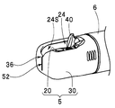
- an opening 31 is provided on the upper surface, which is one surface of the cover 30.
- the opening 31 has a first opening 31a and a second opening 31b and is formed as one opening. That is, a part of the first opening 31a and a part of the second opening 31b are connected to form the opening 31.
- the first opening 31a has a substantially rectangular shape, and is a raising base opening through which the raising base 40 protrudes and sinks by exposing the raising base accommodation space 24 provided in the tip member 20.
- the second opening 31b is a lens exposure opening that has a substantially rectangular shape and exposes the illumination lens 41 and the observation lens 42 provided on the upper surface 25 of the tip member 20.
- a cover front end surface indicated by reference numeral 32, a left side surface of the cover indicated by reference numeral 33, and a right side surface of the cover indicated by reference numeral 34 are provided.
- the cover front end surface 32 is the most advanced surface of the insertion portion 2.
- the cover left side surface 33 is a side surface located on the left side when the cover front end surface 32 is viewed from the front, and the cover right side surface 34 is located on the opposite right side across the cover left side surface 33 and the insertion portion longitudinal axis 2a. This is the other side.
- the inner surface of the cover 30 is provided with a planned fracture portion 35 and a locking projection 39.
- the planned break portion 35 has a break start point 36, a first thin portion 37, and a second thin portion 38.
- the break start point 36 is a notch provided in the inner surface of the first opening 31a and the peripheral edge 32b on the cover front end surface 32 side.
- the break start point 36 is also a notification unit that notifies the break point to be broken first when the cover 30 is removed from the tip member 20.
- the first thin portion 37 is a first groove provided along the insertion portion longitudinal axis 2a on the inner surface of the lower surface facing the first opening 31a.
- the first groove has a V shape, a semicircular shape, and a concave shape, and the groove tip is located on the inner surface of the cover tip surface 32.
- the second thin portion 38 is a second groove provided on the inner surface of the cover front end surface 32, and is formed so as to be continuous from the break start point 36 to the groove front end of the first groove.
- the shape of the second groove is the same as that of the first groove, and is a V shape, a semicircular shape, or a concave shape.
- the locking convex portion 39 is a convex portion that constitutes the other side of the locking portion, and is provided on the tip side from the opening 31.
- the locking projection 39 is provided on the inner surface of the cover left side surface 33 at a position spaced a predetermined distance from the inner surface of the cover front end surface 32.
- the break start point 36 is located on the distal end side of the insertion portion longitudinal axis 2 a with respect to the locking convex portion 39.
- the locking projection 39 is engaged with the locking groove 26.
- the locking projection 39 is shaped to protrude from the inner surface at a predetermined width with a predetermined width so as to be engaged and arranged in a predetermined state with respect to the locking groove 26.
- Reference numeral 30E denotes an attachment portion, which is an annular portion having a predetermined elasticity.
- Reference numeral 30h denotes a connection hole, which is a through hole formed in the attachment portion 30E.
- the cover 30 is disposed on the tip member 20 so as to constitute the tip portion 5 shown in FIGS. 4A-5.
- the inner peripheral surface of the connection hole 30h provided in the attachment portion 30E is closely attached to the outer peripheral surface of the tip portion main body 21 by the elastic force of the attachment portion 30E.
- the locking projection 39 is engaged and arranged in the locking groove 26 to be engaged.
- the tip portion 5 in which the cover 30 is securely fixed to the tip member 20 is formed.
- most of the planned fracture portion 35 provided in the first opening 31 a of the opening 31 is disposed at a position separated from the metal portion of the tip member 20.
- the removal of the cover 30 will be described with reference to FIGS. 7A to 7D.
- the operator wears gloves.
- the worker prepares, for example, a nipper in advance as a cutting tool.
- the operator When the worker starts the cleaning operation, first, the operator operates the elevator control lever 14 to bring the elevator 40 disposed in the elevator storage space 24 upside down. As a result, the cutting tool arrangement space 24 ⁇ / b> S is provided on the front end side of the raising base accommodation space 24.
- the cutting tool arrangement space 24S can be provided in the raising base accommodating space 24 by bringing the raising stand 40 into the raised state.
- the position of the second thin portion 38 and the position of the first thin portion 37 provided on the cover 30 can be easily confirmed visually without being blocked by the elevator 40.
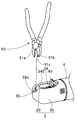
- the operator performs cutting work by arranging the blades 51a and 51b of the nipper 50 in the vicinity of the break start point 36 of the cover 30 as shown by the arrows.
- the worker places one blade 51b in the cutting tool placement space 24S, places the blade 51b along the first wall surface 22w, and places the blade surface 51c along the second thin portion 38. Disconnect.
- a cut 52 which is a fracture portion is formed in the cover front end surface 32.
- the break start point 36 on the peripheral edge portion 32b the operator can easily grasp the site to be broken first by the nipper 50.
- the operator can cut along the second thin portion 38 with a small amount of force to form a cut 52 in the cover front end surface 32. it can.
- the operator holds and holds the cover left side 33 side of the cover front end surface 32 with the blades 51 a and 51 b of the nipper 50.
- the operator performs a hand operation to move the nipper 50 as indicated by an arrow, and tears (breaks) the cover front end surface 32 held by the nipper 50 as indicated by a broken line.
- the cover 30 is gradually cut along the second thin portion 38 and the first thin portion 37, and a part of the cover 30 is gradually separated from the insertion portion longitudinal axis 2a as shown by the broken line arrow in FIG. 7D. It will be destroyed while expanding.
- the locking projection 39 is removed from the locking groove 26 as indicated by the solid arrow, and the locked state is released. Thereafter, the operator tears the cover 30 along the first thin portion 37. As a result, the cover 30 is removed from the tip body 21. Thereafter, the operator shifts to a cleaning operation.
- the planned break portion 35 including the break start point 36, the first thin portion 37, and the second thin portion 38 is provided in the first opening 31 a of the opening 31 provided in the cover 30.
- the front end member 20 is configured by covering the cover 30 with the front end member 20, most of the expected breakage portion 35 provided in the cover 30 is provided in the raising base accommodating space 24.
- the operator can easily remove the cover 30 from the tip member 20 by breaking the cover 30 with the fingers wearing gloves and using the cutting tool as described above.
- the second thin portion 38 is provided on the inner surface of the cover front end surface 32.
- the planned fracture portion 35 may be constituted by the fracture start point 36 and the first thin portion 37.
- the cover front end surface 32 is easily cut from the breaking start point 36 with a small amount of force by the nipper to form the cut 52. can do.
- the operator can tear and destroy the cover 30 by holding the cover left side 33 side of the cover front end surface 32 with the blades 51a and 51b of the nipper 50 in the same manner as described above.
- the cover left side 33 side of the cover front end surface 32 is sandwiched and held by the blades 51 a and 51 b of the nipper 50, and the cover front end surface 32 held by the nipper 50 is torn.
- the finger after forming the notch 52 with a nipper or the like, without using the nipper or the like, the finger is placed in the depression 27 and the vicinity thereof, and the cover left side 33 side of the cover front end surface 32 is held, 30 can be torn and destroyed.
- the locking convex portion 39 is provided on the inner surface of the cover left side surface 33.
- a locking projection 39 a may be provided on the inner surface of the cover right side 34 in addition to the inner surface of the cover left side 33.
- the locking projections 39 and 39a may be provided on the inner surfaces of both side surfaces 33 and 34 of the cover 30, respectively.
- the front end member 20 has a locking groove 26 corresponding to the locking projection 39 on the left side surface 33 of the cover, and a locking corresponding to the locking projection 39a of the right side surface 34 of the cover.
- a groove 26a is provided.
- Other configurations are the same as those in the above-described embodiment, and the same members are denoted by the same reference numerals and description thereof is omitted.
- the cover 30 can be reliably fixed by the tip member 20.
- the present invention is not limited to the above-described embodiments, and various modifications can be made without departing from the spirit of the invention.
- the second thin portion 38 may be disposed so as to extend obliquely inside the front surface of the cover 30 so as to connect the break start point 36 and the first thin portion 37.
- the present invention it is possible to realize a distal end cover of an endoscope that can be easily detached from the distal end member even with a gloved finger and prevented from falling off from the distal end member during use.
Landscapes
- Health & Medical Sciences (AREA)
- Life Sciences & Earth Sciences (AREA)
- Surgery (AREA)
- Nuclear Medicine, Radiotherapy & Molecular Imaging (AREA)
- Biomedical Technology (AREA)
- Optics & Photonics (AREA)
- Pathology (AREA)
- Radiology & Medical Imaging (AREA)
- Biophysics (AREA)
- Engineering & Computer Science (AREA)
- Physics & Mathematics (AREA)
- Heart & Thoracic Surgery (AREA)
- Medical Informatics (AREA)
- Molecular Biology (AREA)
- Animal Behavior & Ethology (AREA)
- General Health & Medical Sciences (AREA)
- Public Health (AREA)
- Veterinary Medicine (AREA)
- Endoscopes (AREA)
Abstract
内視鏡挿入部2の起上台40が設けられた先端部材20に装着される、内視鏡1のカバー30において、先端部材20の、起上台40が収容される起上台収容空間24を外部に露呈させる開口31を形成する周縁部32bと、周縁部32bに配置された破断開始点36と、開口31と対向する面の内面に、破断開始点36から破断された周縁部32bの破断部が接続される第1の薄肉部37と、を備えた破断予定部35と、先端部材20の外面に対し、外面と交差する方向に係合して係止される係止凸部39と、を具備している。
Description
本発明は、内視鏡挿入部の先端部を構成する起上台が設けられる先端部材に取り付けられる内視鏡の先端カバーに関する。
医療用の内視鏡の一つに、挿入部の先端側側面に照明レンズ及び対物レンズを配列した側視型内視鏡(以下、内視鏡と記載する)、所謂、十二指腸用内視鏡がある。
内視鏡には、処置具チャンネル及び起上装置が設けられている。
内視鏡には、処置具チャンネル及び起上装置が設けられている。
処置具チャンネル内には、造影チューブ、バスケットカテーテル、バルーンカテーテル等の処置具が挿通される。処置具チャンネルを通過した処置具は、先端部材に設けられた先端開口から外部に導出され、起上装置によって導出方向が所望する方向に切り換えられるようになっている。
起上装置は、一般的に、先端部材に回動自在に配設される起上台と、操作部に設けられた起上台操作レバーと、起上台操作レバーの操作に伴って移動して起上台を揺動させる起上台操作ワイヤと、で主に構成されている。
そして、先端部材には電気絶縁性の内視鏡の先端カバーが外装されている。先端カバーは、先端部材からの脱落を防止するため接着剤等により固定されている。
内視鏡は、使用後、洗浄、消毒される。内視鏡の挿入部を洗浄する場合,先端部から先端カバーを取外すことによって処置具チャンネルの先端口を露出させて洗浄を容易におこなえることが知られている。
例えば、日本国特許4855824号公報には挿入部を構成する軟性の部材を傷つけることなく、内視鏡用先端カバーを引き裂いて破壊して先端部材から内視鏡用先端カバーを取り外すことができるとともに、使用中の脱落を防止することができる内視鏡用先端カバー、内視鏡装置、及び内視鏡装置における内視鏡の先端カバーの取り外し方法が開示されている。
内視鏡用先端カバーには、指掛け部を起点に塑性変形させることによって第1の係止部、第2の係止部、第3の係止部による係止状態を順次解除するための塑性変形部である薄肉部及び凹溝が設けられている。
薄肉部は、内視鏡の先端カバーの指掛け部と開口部との間の側面部に設けられている。
凹溝は、薄肉部の基端部、又は基端部の近傍から内視鏡用先端カバーの側面部、前面部、逆側の側面部にかけての全周にわたる内周面に形成されている。
しかしながら、前述した内視鏡用先端カバーを、前記指掛け部を起点に全周に渡って切り裂く作業は、手指の力の弱い作業者にとっては難しい作業である。そのうえ、使用後の内視鏡を洗浄、消毒する際、作業者は、感染物質の付着および消毒液の付着を避けるため、防水性、耐薬品性の手袋を装着する。手袋を装着した手指で指掛け部を把持することは難しい。
しかしながら、前述した内視鏡用先端カバーを、前記指掛け部を起点に全周に渡って切り裂く作業は、手指の力の弱い作業者にとっては難しい作業である。そのうえ、使用後の内視鏡を洗浄、消毒する際、作業者は、感染物質の付着および消毒液の付着を避けるため、防水性、耐薬品性の手袋を装着する。手袋を装着した手指で指掛け部を把持することは難しい。
本発明は、上記事情に鑑みてなされたものであり、手袋をした手指でも先端部材からの取り外しが容易で、使用中における先端部材からの脱落を防止した内視鏡の先端カバーを提供することを目的にしている。
本発明の一態様の内視鏡の先端カバーは、内視鏡挿入部の起上台が設けられた先端部材に装着される、内視鏡の先端カバーにおいて、前記先端部材の、前記起上台が収容される空間を外部に露呈させる開口を形成する周縁部と、前記周縁部に配置された破断開始点と、前記開口と対向する面の内面に、前記破断開始点から破断された前記周縁部の破断部が接続される薄肉部と、を備えた破断予定部と、前記先端部材の外面に対し、該外面と交差する方向に係止される係止部と、を具備している。
以下、図面を参照して本発明の実施の形態を説明する。
なお、以下の説明に用いる各図において、各構成要素を図面上で認識可能な程度の大きさとするため、構成要素毎に縮尺を異ならせてあるものもある。また、本発明は、これらの図に記載された構成要素の数量、構成要素の形状、構成要素の大きさの比率、及び各構成要素の相対的な位置関係のみに限定されるものではない。
なお、以下の説明に用いる各図において、各構成要素を図面上で認識可能な程度の大きさとするため、構成要素毎に縮尺を異ならせてあるものもある。また、本発明は、これらの図に記載された構成要素の数量、構成要素の形状、構成要素の大きさの比率、及び各構成要素の相対的な位置関係のみに限定されるものではない。
本実施の形態において、内視鏡は、側視型の内視鏡である。先端カバーは、側視型の内視鏡に装着される側視型内視鏡の先端カバーである。
図1に示すように内視鏡1は、被検体内に挿入される挿入部2と、挿入部2の基端側に設けられた操作部3と、操作部3から延出するユニバーサルコード4と、を備えて構成されている。
図1に示すように内視鏡1は、被検体内に挿入される挿入部2と、挿入部2の基端側に設けられた操作部3と、操作部3から延出するユニバーサルコード4と、を備えて構成されている。
内視鏡1の操作部3には、湾曲操作装置11と、送気送水釦12と、吸引釦13と、起上台操作レバー14と、各種操作スイッチ15と、が設けられている。
操作スイッチ15は、フリーズ信号を発生させるフリーズスイッチ、写真撮影を行なう際のレリーズ信号を発生させるレリーズスイッチ、観察モードの切り換え指示を行うための観察モード切り換えスイッチ等である。
操作スイッチ15は、フリーズ信号を発生させるフリーズスイッチ、写真撮影を行なう際のレリーズ信号を発生させるレリーズスイッチ、観察モードの切り換え指示を行うための観察モード切り換えスイッチ等である。
操作部3には、処置具(不図示)を体内に導入するための処置具挿入口16が設けられている。処置具挿入口16には処置具チャンネルチューブ17の一端側が接続されている。処置具チャンネルチューブ17の他端側は、挿入部2の先端部5を構成する先端部材(図3等の符号20参照)に接続されている。
操作部3から延出されている挿入部2は、先端側から順に先端部5と、湾曲部6と、可撓管部7と、を連設して構成されている。
可撓管部7は、図示されていない例えば、螺旋管と、螺旋管を被覆する網状管と、最外層を構成する熱収縮チューブと、を設けて構成されている。湾曲部6は、例えば上下左右の4方向に湾曲するように構成された湾曲駒組と、湾曲駒組を被覆する金属製の網状管と、外皮である湾曲ゴムと、を設けて構成されている。
湾曲部6は、操作部3に設けられた湾曲操作装置11の上下湾曲ノブ11aを回動操作することにより上方向又は下方向に湾曲し、左右湾曲ノブ11bを回動操作することにより左方向又は右方向に湾曲する構成になっている。
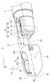
図2に示すように先端部5は、先端部材20に内視鏡の先端カバー(以下、カバーと略記する)30を装着して構成される。
先端部材20は、先端部5を構成する硬質部材であり、カバー30は、電気絶縁性を有する例えば樹脂製であって、予め定めた弾発性を有する。
先端部材20は、先端部5を構成する硬質部材であり、カバー30は、電気絶縁性を有する例えば樹脂製であって、予め定めた弾発性を有する。
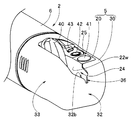
先端部材20は、樹脂製で電気絶縁性を有する先端部本体21と、先端部本体21から挿入部長手軸2aに沿って先端側に突出する金属製の光学用凸部22及び同じく金属製の起上用凸部23と、を有している。光学用凸部22と起上用凸部23との間の隙間は、起上台収容空間24であって、起上台40が回動自在に収容配置される。
起上台40は、硬質部材であって、金属製或いは樹脂製である。
起上台40は、硬質部材であって、金属製或いは樹脂製である。
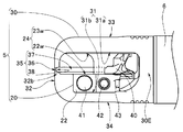
具体的に、起上台40は、図5に示すように対向して起上台収容空間24を構成する第1壁面22wと第2壁面23wとの間に配置されて回動自在である。第1壁面22wは、光学用凸部22の内面壁であり、第2壁面23wは、起上用凸部23の内面壁である。
図2、図5に示すように光学用凸部22の一面である上面25の予め定めた位置には照明レンズ41及び観察レンズ42が設けられている。符号43は、洗浄ノズルである。
洗浄ノズル43からは流体が噴出される。照明レンズ41の表面及び観察レンズ42の表面に付着した汚れは、洗浄ノズル43から噴出される流体によって除去される。
洗浄ノズル43からは流体が噴出される。照明レンズ41の表面及び観察レンズ42の表面に付着した汚れは、洗浄ノズル43から噴出される流体によって除去される。
起上用凸部23にはアーム用凹部(図6の符号23a参照)および、係止部の一方を構成する係止溝26が形成されている。係止溝26には後述する係止凸部39が係入配置される。
アーム用凹部23a内には起上台動作アーム23bが配設されるようになっている。起上台動作アームには起上台40に固設される軸部(不図示)が設けられている。軸部は、アーム用凹部内から貫通孔(不図示)を介して起上台収容空間24内に導出されて起上台40に一体に固定される。
起上用凸部23はアーム用凹部23aを形成しなくてもよい。その場合、起上台動作アーム23bは配置されず、起上台操作ワイヤが直接起上台40に接続されている。
起上用凸部23はアーム用凹部23aを形成しなくてもよい。その場合、起上台動作アーム23bは配置されず、起上台操作ワイヤが直接起上台40に接続されている。
なお、上面とは、湾曲部6の上湾曲方向に対応する面を示している。
一方、カバー30の一面である上面には開口31が設けられている。開口31は、第1開口部31aと、第2開口部31bと、を有して1つの開口として形成されている。すなわち、第1開口部31aの一部と第2開口部31bの一部が繋がって開口31が構成されている。
第1開口部31aは、略矩形形状であって、先端部材20に設けられた起上台収容空間24を露呈させて起上台40が突没する起上台開口部である。
これに対して、第2開口部31bは、略矩形形状であって、先端部材20の上面25に設けられた照明レンズ41及び観察レンズ42を露呈させるレンズ露呈開口部である。
これに対して、第2開口部31bは、略矩形形状であって、先端部材20の上面25に設けられた照明レンズ41及び観察レンズ42を露呈させるレンズ露呈開口部である。
カバー30の上面と、上面に対向する他面である下面との間には、符号32に示すカバー先端面、符号33に示すカバー左側面、符号34に示すカバー右側面が設けられている。
カバー先端面32は、挿入部2の最先端面である。カバー左側面33は、カバー先端面32を正面から見たとき左側に位置する一側面であり、カバー右側面34は、カバー左側面33と挿入部長手軸2aを挟んで反対の右側に位置する他側面である。
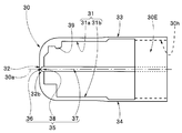
図2、図3に示すようにカバー30の内面には、破断予定部35と、係止凸部39と、が設けられている。
本実施形態において、破断予定部35は、破断開始点36と、第1薄肉部37と、第2薄肉部38と、を有している。
本実施形態において、破断予定部35は、破断開始点36と、第1薄肉部37と、第2薄肉部38と、を有している。
破断開始点36は、第1開口部31aの内面及びカバー先端面32側の周縁部32bに設けられた切欠部である。破断開始点36は、カバー30を先端部材20から取り外す際に最初に破断するべき破断点を告知する告知部でもある。
第1薄肉部37は、第1開口部31aに対向する下面の内面に挿入部長手軸2aに沿って設けられた第1溝である。第1溝は、V字形状、半円形形状、凹字形状であり、溝先端は、カバー先端面32の内面に位置している。
第2薄肉部38は、カバー先端面32の内面に設けられた第2溝であり、破断開始点36から第1溝の溝先端に連続するように形成されている。第2溝の形状は、第1溝と同様な形成状であり、V字形状、半円形形状、凹字形状である。
係止凸部39は、係止部の他方を構成する凸部であって、開口31より先端側に設けられている。具体的に、係止凸部39は、カバー左側面33の内面にカバー先端面32の内面から予め定めた距離離間した位置に設けられている。言い換えれば、破断開始点36は、係止凸部39よりも挿入部長手軸2aの先端側に位置している。
係止凸部39は、係止溝26に係入配置される。そして、係止凸部39は、係止溝26に対して予め定めた状態で係入配置されるように予め定めた幅で内面から予め定めた高さ突出して形作られている。
なお、符号30Eは取付部であり、予め定めた弾発性を有する環状部である。符号30hは、連結孔であって、取付部30Eに形成された貫通孔である。
なお、符号30Eは取付部であり、予め定めた弾発性を有する環状部である。符号30hは、連結孔であって、取付部30Eに形成された貫通孔である。
図2の矢印Y2に示すようにカバー30は、先端部材20に被覆配置されて図4A-図5に示す先端部5を構成する。
このとき、取付部30Eに設けられた連結孔30hの内周面が先端部本体21の外周面に該取付部30Eの弾発力によって密着配置される。加えて、係止凸部39が係止溝26に係入配置されて係合状態になる。
この結果、カバー30が先端部材20に確実に固定された先端部5が構成される。この固定状態において、開口31の第1開口部31aに設けられた破断予定部35の大部分が先端部材20の金属部分から離間した位置に配置される。
ここで、図7A-図7Dを参照してカバー30の取り外しを説明する。
使用後の内視鏡1を洗滌、消毒する際、作業者は、手袋を装着する。また、作業者は、予め、切断具として例えばニッパーを用意する。
使用後の内視鏡1を洗滌、消毒する際、作業者は、手袋を装着する。また、作業者は、予め、切断具として例えばニッパーを用意する。
作業者は、洗浄作業を開始する際、まず、起上台操作レバー14を手元操作して起上台収容空間24内に倒置配置されている起上台40を起上状態にする。この結果、起上台収容空間24の先端側に切断具配置スペース24Sが設けられる。
このように、起上台40を起上状態にすることによって、起上台収容空間24に切断具配置スペース24Sを設けることができる。この結果、カバー30に設けられた第2薄肉部38の位置及び第1薄肉部37の位置を起上台40によって遮られること無く目視にて容易に確認することができる。
次に、作業者は、図7Aに示すようにニッパー50の刃51a,51bを矢印に示すようにカバー30の破断開始点36近傍に配置して切断作業を行う。このとき、作業者は、一方の刃51bを切断具配置スペース24S内に配置し、該刃51bを第1壁面22wに沿わせて配置し、刃面51cを第2薄肉部38に沿わせて切断する。
この結果、図7Bに示すようにカバー先端面32に破断部である切込み52が形成される。
このように、破断開始点36を周縁部32bに設けたことによって、作業者は、ニッパー50で最初に破断するべき部位を容易に把握することができる。また、カバー先端面32の内面に第2薄肉部38を設けたことによって、作業者は、第2薄肉部38に沿って小さな力量で切断してカバー先端面32に切込み52を形成することができる。
次いで、作業者は、ニッパー50の刃51a,51bでカバー先端面32のカバー左側面33側を挟持保持する。ここで、作業者は、ニッパー50を矢印に示すように移動させる手元操作を行って該ニッパー50で保持されたカバー先端面32を破線に示すように引き裂いて(破断して)いく。
このとき、カバー30は、第2薄肉部38、第1薄肉部37に沿って徐々に切り裂かれ、図7Dの破線矢印に示すようにカバー30の一部が挿入部長手軸2aから徐々離間するように拡げられつつ破壊されていく。
この結果、係止凸部39が実線矢印に示すように係止溝26から取り外されて係止状態が解除される。その後、作業者がカバー30を第1薄肉部37に沿って切り裂いていく。このことによって、カバー30が先端部本体21から取り外される。その後、作業者は、洗浄作業に移行する。
このように、カバー30に設けられた開口31の第1開口部31aに破断開始点36、第1薄肉部37、第2薄肉部38を含む破断予定部35を設ける。この結果、カバー30を先端部材20に被覆して先端部5を構成したとき、カバー30に設けられている破断予定部35の大部分を起上台収容空間24内に設けられる。
このため、作業者は、カバー30を先端部材20から取り外す際、切断具を挿入部2を構成する湾曲ゴムを傷付けること無く、起上台収容空間24の先端側に設けられる切断具配置スペース24Sに配置することができる。
この結果、作業者は、手袋を装着した手指で切断具を用いて、上述したようにカバー30を破壊して先端部材20からの取り外しを容易に行える。
なお、上述した実施形態においては、カバー先端面32の内面に第2薄肉部38を設けるとしている。しかし、破断予定部35を破断開始点36と、第1薄肉部37と、で構成してもよい。
この構成によれば、カバー先端面32の肉厚を切りやすさを考慮して設定することによって、ニッパーで容易に破断開始点36から小さな力量でカバー先端面32を切断して切込み52を形成することができる。
そして、切り込み形成後は、上述と同様に、作業者は、ニッパー50の刃51a,51bでカバー先端面32のカバー左側面33側を挟持保持してカバー30を引き裂いて破壊することができる。
また、上述した実施形態においては、ニッパー50の刃51a,51bでカバー先端面32のカバー左側面33側を挟持保持し、該ニッパー50で保持されたカバー先端面32を引き裂くとしている。
しかし、図8Aに示すように起上用凸部23の先端側に予め定め形状の切欠面23Cを形成することによって、先端部5に図8Bに示すようにカバー30の内面と切欠面23Cとの間に指先を配設可能な窪み27を設けるようにしてもよい。
なお、その他の構成は、上述した実施形態と同様であり、同部材には同符号を付して説明を省略している。
この構成によれば、ニッパー等で切込み52を形成した後、ニッパー等を用いること無く、手指を窪み27及びその近傍に配置してカバー先端面32のカバー左側面33側を保持して、カバー30を引き裂いて破壊することができる。
また、上述した実施形態においては、係止凸部39をカバー左側面33の内面に設けるとしている。しかし、図9Aに示すようにカバー左側面33の内面に加えてカバー右側面34の内面に係止凸部39aを設けるようにしてもよい。
つまり、カバー30の両側面33,34の内面にそれぞれ係止凸部39,39aを設けてもよい。この場合、図9Bに示すように先端部材20にはカバー左側面33の係止凸部39に対応する係止溝26に加えて、カバー右側面34の係止凸部39aに対応する係止溝26aを設ける。
なお、その他の構成は、上述した実施形態と同様であり、同部材には同符号を付して説明を省略している。
なお、その他の構成は、上述した実施形態と同様であり、同部材には同符号を付して説明を省略している。
この構成によれば、カバー30を先端部材20により確実に固定することができる。
尚、本発明は、以上述べた実施形態のみに限定されるものではなく、発明の要旨を逸脱しない範囲で種々変形実施可能である。
例えば、上述した実施形態にて開示した第1薄肉部37を、カバー30の側面にて長手軸2aに平行になるよう配置してもよい。この場合、第2薄肉部38は、破断開始点36と第1薄肉部37との間を繋ぐよう、カバー30の前面内側に斜めに延びるよう配置すればよい。
尚、本発明は、以上述べた実施形態のみに限定されるものではなく、発明の要旨を逸脱しない範囲で種々変形実施可能である。
例えば、上述した実施形態にて開示した第1薄肉部37を、カバー30の側面にて長手軸2aに平行になるよう配置してもよい。この場合、第2薄肉部38は、破断開始点36と第1薄肉部37との間を繋ぐよう、カバー30の前面内側に斜めに延びるよう配置すればよい。
本発明によれば、手袋をした手指でも先端部材からの取り外しが容易で、使用中における先端部材からの脱落を防止した内視鏡の先端カバーを実現できる。
本出願は、2015年7月15日に日本国に出願された特願2015-141534号を優先権主張の基礎として出願するものであり、上記の開示内容は、本願明細書、請求の範囲に引用されるものとする。
Claims (15)
- 内視鏡挿入部の起上台が設けられた先端部材に装着される、内視鏡の先端カバーにおいて、
前記先端部材の、前記起上台が収容される空間を外部に露呈させる開口を形成する周縁部と、
前記周縁部に配置された破断開始点と、前記開口と対向する面の内面に、前記破断開始点から破断された前記周縁部の破断部が接続される薄肉部と、を備えた破断予定部と、
前記先端部材の外面に対し、該外面と交差する方向に係合して係止される係止部と、
を具備することを特徴とする内視鏡の先端カバー。 - 内視鏡挿入部の起上台が設けられた先端部材に装着される、内視鏡の先端カバーにおいて、
前記先端部材の、前記起上台が収容される空間を外部に露呈させる開口を形成する周縁部と、
前記周縁部に配置された破断開始点と、前記周縁部と前記開口と対向する面を接続する少なくとも一つの側面の内面に、前記破断開始点から破断された前記周縁部の破断部が接続される薄肉部と、を備えた破断予定部と、
前記先端部材の外面に対し、該外面と交差する方向に係合して係止される係止部と、
を具備することを特徴とする内視鏡の先端カバー。 - 前記薄肉部は、前記先端カバーの後端まで伸びるよう設けられていることを特徴とする、請求項1に記載の内視鏡の先端カバー。
- 前記係止部は、前記周縁部と前記開口と対向する面とを接続する少なくとも一つの側面の内面に設けられることを特徴とする、請求項1に記載の内視鏡の先端カバー。
- 前記破断予定部は、前記破断開始点及び前記薄肉部に加えて、前記カバー先端面の内面に前記破断開始点から前記薄肉部に延設される他の薄肉部を有することを特徴とする、請求項1に記載の内視鏡の先端カバー。
- 前記他の薄肉部は、前記カバーの内面に設けられた溝であることを特徴とする、請求項5に記載の内視鏡の先端カバー。
- 前記係止部は、前記周縁部と前記開口と対向する面との間に設けられる両側面の内面にそれぞれ設けることを特徴とする、請求項1に記載の内視鏡の先端カバー。
- 前記破断予定部を形成する前記破断開始点、前記他の薄肉部、及び前記薄肉部の一部が前記先端部材の金属部分より離間した位置に配置されることを特徴とする、請求項6に記載の内視鏡の先端カバー。
- 内視鏡挿入部の先端部を構成する起上台が設けられた先端部材に装着される内視鏡の先端カバーにおいて、
前記起上台が収容される空間を露呈させる開口部を形成する周縁部と、
前記先端部材に係止される係止部と、
前記係止部が前記先端部材に係止された係止状態を解除する際に破断される、前記周縁部のカバー先端面側に設けられた破断開始点と、該周縁部を有する一面に対向する他面の内面に該カバー先端面側から基端部まで該内視鏡挿入部の長手軸に沿って延設される薄肉部と、を備えた破断予定部と、
を具備することを特徴とする内視鏡の先端カバー。 - 前記係止部は、前記一面と前記他面との間に設けられる少なくとも一方の側面の内面に設けられることを特徴とする請求項9に記載の内視鏡の先端カバー。
- 前記破断予定部は、前記破断開始点及び前記薄肉部に加えて、前記カバー先端面の内面に前記破断開始点から前記薄肉部に延設される他の薄肉部を有することを特徴とする、請求項9に記載の内視鏡の先端カバー。
- 前記薄肉部及び前記他の薄肉部は前記カバーの内面に設けられた溝であることを特徴とする、請求項11に記載の内視鏡の先端カバー。
- 前記係止部を構成する係止溝が設けられる凸部の先端側に切欠面を形成して、前記先端部を構成する前記カバーの内面と前記先端部材の切欠面との間に指先を配設可能な窪みを設けたことを特徴とする、請求項12に記載の内視鏡の先端カバー。
- 前記係止部は、前記一面と前記他面との間に設けられる両側面の内面にそれぞれ設けることを特徴とする、請求項9に記載の内視鏡の先端カバー。
- 前記破断予定部を形成する前記破断開始点、前記他の薄肉部、及び前記薄肉部の一部が前記先端部材の金属部分より離間した位置に配置されることを特徴とする、請求項12に記載の内視鏡の先端カバー。
Priority Applications (4)
| Application Number | Priority Date | Filing Date | Title |
|---|---|---|---|
| CN201680003616.1A CN106999007B (zh) | 2015-07-15 | 2016-03-31 | 内窥镜的前端罩和内窥镜 |
| JP2016563147A JP6099851B1 (ja) | 2015-07-15 | 2016-03-31 | 内視鏡の先端カバーおよび内視鏡 |
| EP16824113.1A EP3205255A4 (en) | 2015-07-15 | 2016-03-31 | Distal end cover for endoscope |
| US15/591,312 US10271715B2 (en) | 2015-07-15 | 2017-05-10 | Distal end cover of endoscope and endoscope |
Applications Claiming Priority (2)
| Application Number | Priority Date | Filing Date | Title |
|---|---|---|---|
| JP2015-141534 | 2015-07-15 | ||
| JP2015141534 | 2015-07-15 |
Related Child Applications (1)
| Application Number | Title | Priority Date | Filing Date |
|---|---|---|---|
| US15/591,312 Continuation US10271715B2 (en) | 2015-07-15 | 2017-05-10 | Distal end cover of endoscope and endoscope |
Publications (1)
| Publication Number | Publication Date |
|---|---|
| WO2017010132A1 true WO2017010132A1 (ja) | 2017-01-19 |
Family
ID=57757304
Family Applications (1)
| Application Number | Title | Priority Date | Filing Date |
|---|---|---|---|
| PCT/JP2016/060684 WO2017010132A1 (ja) | 2015-07-15 | 2016-03-31 | 内視鏡の先端カバー |
Country Status (5)
| Country | Link |
|---|---|
| US (1) | US10271715B2 (ja) |
| EP (1) | EP3205255A4 (ja) |
| JP (1) | JP6099851B1 (ja) |
| CN (1) | CN106999007B (ja) |
| WO (1) | WO2017010132A1 (ja) |
Cited By (1)
| Publication number | Priority date | Publication date | Assignee | Title |
|---|---|---|---|---|
| JP2020121155A (ja) * | 2016-07-19 | 2020-08-13 | Hoya株式会社 | 内視鏡用キャップ、および、内視鏡用キャップの取り外し方法 |
Families Citing this family (7)
| Publication number | Priority date | Publication date | Assignee | Title |
|---|---|---|---|---|
| WO2017122694A1 (ja) * | 2016-01-14 | 2017-07-20 | オリンパス株式会社 | 内視鏡用カバー、内視鏡及びカバーユニット |
| DE102016114881A1 (de) * | 2016-08-11 | 2018-02-15 | Digital Endoscopy Gmbh | Endoskopkopf, Endoskop und Albarranhebelhalteelement |
| JP6947740B2 (ja) * | 2016-10-14 | 2021-10-13 | Hoya株式会社 | 起上台 |
| DE102016122477A1 (de) * | 2016-11-22 | 2018-05-24 | Digital Endoscopy Gmbh | Endoskopkopf und endoskop mit diesem |
| DE112017006133T5 (de) * | 2016-12-02 | 2019-08-14 | Olympus Corporation | Distalendabdeckung für ein Endoskop |
| CN111629650B (zh) * | 2018-01-31 | 2024-02-27 | 奥林巴斯株式会社 | 插入器具用清洗工具 |
| CN111757697A (zh) * | 2018-02-23 | 2020-10-09 | 富士胶片株式会社 | 内窥镜 |
Citations (4)
| Publication number | Priority date | Publication date | Assignee | Title |
|---|---|---|---|---|
| JPH08140924A (ja) * | 1994-11-16 | 1996-06-04 | Asahi Optical Co Ltd | 内視鏡の先端部 |
| JPH09299315A (ja) * | 1996-05-16 | 1997-11-25 | Olympus Optical Co Ltd | 内視鏡 |
| JPH10216075A (ja) * | 1997-02-10 | 1998-08-18 | Olympus Optical Co Ltd | 内視鏡 |
| JP2002017654A (ja) * | 2001-05-30 | 2002-01-22 | Olympus Optical Co Ltd | 内視鏡 |
Family Cites Families (16)
| Publication number | Priority date | Publication date | Assignee | Title |
|---|---|---|---|---|
| US5104379A (en) * | 1989-04-03 | 1992-04-14 | Olympus Optical Co., Ltd. | Medical instrument and valve to be mounted on a mount piece of that instrument |
| US5359991A (en) * | 1991-04-24 | 1994-11-01 | Asahi Kogaku Kogyo Kabushiki Kaisha | Cover device for endoscope |
| US5674182A (en) * | 1993-02-26 | 1997-10-07 | Olympus Optical Co., Ltd. | Endoscope system including endoscope and protection cover |
| US5569157A (en) * | 1993-05-07 | 1996-10-29 | Olympus Optical Co., Ltd. | Endoscope |
| US5868663A (en) * | 1996-03-26 | 1999-02-09 | Asahi Kogaku Kogyo Kabushiki Kaisha | Front end structure of side-view type endoscope |
| US5860913A (en) * | 1996-05-16 | 1999-01-19 | Olympus Optical Co., Ltd. | Endoscope whose distal cover can be freely detachably attached to main distal part thereof with high positioning precision |
| JP3634671B2 (ja) * | 1999-06-21 | 2005-03-30 | ペンタックス株式会社 | 内視鏡 |
| JP2003102668A (ja) * | 2001-09-28 | 2003-04-08 | Fuji Photo Optical Co Ltd | 内視鏡の先端キャップ |
| US7762949B2 (en) * | 2003-10-16 | 2010-07-27 | Granit Medical Innovation, Llc | Endoscope with open channels |
| JP4171478B2 (ja) * | 2005-06-16 | 2008-10-22 | オリンパスメディカルシステムズ株式会社 | 内視鏡用栓体 |
| JP4855824B2 (ja) | 2006-04-25 | 2012-01-18 | オリンパスメディカルシステムズ株式会社 | 内視鏡用先端カバー、内視鏡装置、及び内視鏡装置における内視鏡の先端カバーの取り外し方法 |
| CN100515319C (zh) * | 2006-05-17 | 2009-07-22 | 奥林巴斯医疗株式会社 | 内窥镜 |
| US20080183038A1 (en) * | 2007-01-30 | 2008-07-31 | Loma Vista Medical, Inc. | Biological navigation device |
| WO2010070984A1 (ja) * | 2008-12-17 | 2010-06-24 | オリンパスメディカルシステムズ株式会社 | フード取付治具 |
| JP5959766B2 (ja) * | 2014-08-06 | 2016-08-02 | オリンパス株式会社 | 内視鏡 |
| JP5959770B2 (ja) * | 2014-08-07 | 2016-08-02 | オリンパス株式会社 | 内視鏡の先端構造 |
-
2016
- 2016-03-31 JP JP2016563147A patent/JP6099851B1/ja active Active
- 2016-03-31 WO PCT/JP2016/060684 patent/WO2017010132A1/ja active Application Filing
- 2016-03-31 CN CN201680003616.1A patent/CN106999007B/zh active Active
- 2016-03-31 EP EP16824113.1A patent/EP3205255A4/en not_active Withdrawn
-
2017
- 2017-05-10 US US15/591,312 patent/US10271715B2/en active Active
Patent Citations (4)
| Publication number | Priority date | Publication date | Assignee | Title |
|---|---|---|---|---|
| JPH08140924A (ja) * | 1994-11-16 | 1996-06-04 | Asahi Optical Co Ltd | 内視鏡の先端部 |
| JPH09299315A (ja) * | 1996-05-16 | 1997-11-25 | Olympus Optical Co Ltd | 内視鏡 |
| JPH10216075A (ja) * | 1997-02-10 | 1998-08-18 | Olympus Optical Co Ltd | 内視鏡 |
| JP2002017654A (ja) * | 2001-05-30 | 2002-01-22 | Olympus Optical Co Ltd | 内視鏡 |
Non-Patent Citations (1)
| Title |
|---|
| See also references of EP3205255A4 * |
Cited By (2)
| Publication number | Priority date | Publication date | Assignee | Title |
|---|---|---|---|---|
| JP2020121155A (ja) * | 2016-07-19 | 2020-08-13 | Hoya株式会社 | 内視鏡用キャップ、および、内視鏡用キャップの取り外し方法 |
| JP7003175B2 (ja) | 2016-07-19 | 2022-01-20 | Hoya株式会社 | 内視鏡用キャップ、および、内視鏡用キャップの取り外し方法 |
Also Published As
| Publication number | Publication date |
|---|---|
| CN106999007A (zh) | 2017-08-01 |
| JP6099851B1 (ja) | 2017-03-22 |
| JPWO2017010132A1 (ja) | 2017-07-27 |
| CN106999007B (zh) | 2018-12-28 |
| EP3205255A4 (en) | 2018-07-18 |
| EP3205255A1 (en) | 2017-08-16 |
| US20170238789A1 (en) | 2017-08-24 |
| US10271715B2 (en) | 2019-04-30 |
Similar Documents
| Publication | Publication Date | Title |
|---|---|---|
| JP6099851B1 (ja) | 内視鏡の先端カバーおよび内視鏡 | |
| JP4855824B2 (ja) | 内視鏡用先端カバー、内視鏡装置、及び内視鏡装置における内視鏡の先端カバーの取り外し方法 | |
| JP5959770B2 (ja) | 内視鏡の先端構造 | |
| KR101706400B1 (ko) | 내시경용 후드 및 이것을 장착한 내시경 | |
| WO2017006684A1 (ja) | 内視鏡用レンズ清掃具 | |
| JP4171478B2 (ja) | 内視鏡用栓体 | |
| JP6275365B1 (ja) | 内視鏡のカバー取り外し治具、内視鏡システム | |
| JP6368888B1 (ja) | 内視鏡の先端カバー | |
| JP2003230531A (ja) | 内視鏡用フード | |
| WO2006013796A1 (ja) | 内視鏡用栓体 | |
| JP6165400B1 (ja) | 内視鏡システム、カバー取り外し具 | |
| JP4383473B2 (ja) | 内視鏡用栓体 | |
| JP2005052229A (ja) | 視野確保装置 | |
| JP4594670B2 (ja) | 内視鏡用処置具栓 | |
| WO2015072330A1 (ja) | 内視鏡先端キャップ及び内視鏡装置 | |
| JP2008212506A (ja) | 内視鏡用先端キャップ及び内視鏡 | |
| WO2015079907A1 (ja) | バルーン取り外し器具 | |
| JP2006055446A (ja) | 内視鏡用鉗子栓 | |
| KR20150101957A (ko) | 오버튜브 및 그 사용법 | |
| WO2019230076A1 (ja) | 内視鏡 | |
| JP6780134B2 (ja) | 内視鏡、先端カバーおよび内視鏡システム | |
| JP5400084B2 (ja) | 栓体及び内視鏡 | |
| WO2021033642A1 (ja) | 内視鏡 | |
| CN213464951U (zh) | 一种内窥镜及一次性头端帽 | |
| JP2006087557A (ja) | 内視鏡スコープ用保護具 |
Legal Events
| Date | Code | Title | Description |
|---|---|---|---|
| ENP | Entry into the national phase |
Ref document number: 2016563147 Country of ref document: JP Kind code of ref document: A |
|
| 121 | Ep: the epo has been informed by wipo that ep was designated in this application |
Ref document number: 16824113 Country of ref document: EP Kind code of ref document: A1 |
|
| REEP | Request for entry into the european phase |
Ref document number: 2016824113 Country of ref document: EP |
|
| NENP | Non-entry into the national phase |
Ref country code: DE |