WO2017010130A1 - ダンパ装置 - Google Patents
ダンパ装置 Download PDFInfo
- Publication number
- WO2017010130A1 WO2017010130A1 PCT/JP2016/060402 JP2016060402W WO2017010130A1 WO 2017010130 A1 WO2017010130 A1 WO 2017010130A1 JP 2016060402 W JP2016060402 W JP 2016060402W WO 2017010130 A1 WO2017010130 A1 WO 2017010130A1
- Authority
- WO
- WIPO (PCT)
- Prior art keywords
- axial direction
- curved surface
- weight members
- weight
- circumferential direction
- Prior art date
- Legal status (The legal status is an assumption and is not a legal conclusion. Google has not performed a legal analysis and makes no representation as to the accuracy of the status listed.)
- Ceased
Links
Images




Classifications
-
- F—MECHANICAL ENGINEERING; LIGHTING; HEATING; WEAPONS; BLASTING
- F16—ENGINEERING ELEMENTS AND UNITS; GENERAL MEASURES FOR PRODUCING AND MAINTAINING EFFECTIVE FUNCTIONING OF MACHINES OR INSTALLATIONS; THERMAL INSULATION IN GENERAL
- F16F—SPRINGS; SHOCK-ABSORBERS; MEANS FOR DAMPING VIBRATION
- F16F15/00—Suppression of vibrations in systems; Means or arrangements for avoiding or reducing out-of-balance forces, e.g. due to motion
- F16F15/10—Suppression of vibrations in rotating systems by making use of members moving with the system
- F16F15/14—Suppression of vibrations in rotating systems by making use of members moving with the system using masses freely rotating with the system, i.e. uninvolved in transmitting driveline torque, e.g. rotative dynamic dampers
- F16F15/1407—Suppression of vibrations in rotating systems by making use of members moving with the system using masses freely rotating with the system, i.e. uninvolved in transmitting driveline torque, e.g. rotative dynamic dampers the rotation being limited with respect to the driving means
- F16F15/145—Masses mounted with play with respect to driving means thus enabling free movement over a limited range
-
- F—MECHANICAL ENGINEERING; LIGHTING; HEATING; WEAPONS; BLASTING
- F16—ENGINEERING ELEMENTS AND UNITS; GENERAL MEASURES FOR PRODUCING AND MAINTAINING EFFECTIVE FUNCTIONING OF MACHINES OR INSTALLATIONS; THERMAL INSULATION IN GENERAL
- F16F—SPRINGS; SHOCK-ABSORBERS; MEANS FOR DAMPING VIBRATION
- F16F15/00—Suppression of vibrations in systems; Means or arrangements for avoiding or reducing out-of-balance forces, e.g. due to motion
- F16F15/10—Suppression of vibrations in rotating systems by making use of members moving with the system
- F16F15/14—Suppression of vibrations in rotating systems by making use of members moving with the system using masses freely rotating with the system, i.e. uninvolved in transmitting driveline torque, e.g. rotative dynamic dampers
- F16F15/1407—Suppression of vibrations in rotating systems by making use of members moving with the system using masses freely rotating with the system, i.e. uninvolved in transmitting driveline torque, e.g. rotative dynamic dampers the rotation being limited with respect to the driving means
- F16F15/145—Masses mounted with play with respect to driving means thus enabling free movement over a limited range
- F16F15/1457—Systems with a single mass
-
- F—MECHANICAL ENGINEERING; LIGHTING; HEATING; WEAPONS; BLASTING
- F16—ENGINEERING ELEMENTS AND UNITS; GENERAL MEASURES FOR PRODUCING AND MAINTAINING EFFECTIVE FUNCTIONING OF MACHINES OR INSTALLATIONS; THERMAL INSULATION IN GENERAL
- F16F—SPRINGS; SHOCK-ABSORBERS; MEANS FOR DAMPING VIBRATION
- F16F15/00—Suppression of vibrations in systems; Means or arrangements for avoiding or reducing out-of-balance forces, e.g. due to motion
- F16F15/10—Suppression of vibrations in rotating systems by making use of members moving with the system
- F16F15/12—Suppression of vibrations in rotating systems by making use of members moving with the system using elastic members or friction-damping members, e.g. between a rotating shaft and a gyratory mass mounted thereon
- F16F15/131—Suppression of vibrations in rotating systems by making use of members moving with the system using elastic members or friction-damping members, e.g. between a rotating shaft and a gyratory mass mounted thereon the rotating system comprising two or more gyratory masses
- F16F15/13128—Suppression of vibrations in rotating systems by making use of members moving with the system using elastic members or friction-damping members, e.g. between a rotating shaft and a gyratory mass mounted thereon the rotating system comprising two or more gyratory masses the damping action being at least partially controlled by centrifugal masses
-
- F—MECHANICAL ENGINEERING; LIGHTING; HEATING; WEAPONS; BLASTING
- F16—ENGINEERING ELEMENTS AND UNITS; GENERAL MEASURES FOR PRODUCING AND MAINTAINING EFFECTIVE FUNCTIONING OF MACHINES OR INSTALLATIONS; THERMAL INSULATION IN GENERAL
- F16F—SPRINGS; SHOCK-ABSORBERS; MEANS FOR DAMPING VIBRATION
- F16F15/00—Suppression of vibrations in systems; Means or arrangements for avoiding or reducing out-of-balance forces, e.g. due to motion
- F16F15/10—Suppression of vibrations in rotating systems by making use of members moving with the system
- F16F15/14—Suppression of vibrations in rotating systems by making use of members moving with the system using masses freely rotating with the system, i.e. uninvolved in transmitting driveline torque, e.g. rotative dynamic dampers
- F16F15/1407—Suppression of vibrations in rotating systems by making use of members moving with the system using masses freely rotating with the system, i.e. uninvolved in transmitting driveline torque, e.g. rotative dynamic dampers the rotation being limited with respect to the driving means
- F16F15/1414—Masses driven by elastic elements
-
- F—MECHANICAL ENGINEERING; LIGHTING; HEATING; WEAPONS; BLASTING
- F16—ENGINEERING ELEMENTS AND UNITS; GENERAL MEASURES FOR PRODUCING AND MAINTAINING EFFECTIVE FUNCTIONING OF MACHINES OR INSTALLATIONS; THERMAL INSULATION IN GENERAL
- F16H—GEARING
- F16H45/00—Combinations of fluid gearings for conveying rotary motion with couplings or clutches
- F16H45/02—Combinations of fluid gearings for conveying rotary motion with couplings or clutches with mechanical clutches for bridging a fluid gearing of the hydrokinetic type
- F16H2045/0221—Combinations of fluid gearings for conveying rotary motion with couplings or clutches with mechanical clutches for bridging a fluid gearing of the hydrokinetic type with damping means
- F16H2045/0263—Combinations of fluid gearings for conveying rotary motion with couplings or clutches with mechanical clutches for bridging a fluid gearing of the hydrokinetic type with damping means the damper comprising a pendulum
Definitions
- Embodiments of the present invention relate to a damper device.
- a damper device including a plurality of weight members each provided with a track and a rotating member to which a number of support portions corresponding to the track of each weight member are attached.
- the damper device of the embodiment is configured to be rotatable around a rotation center, for example, and has a plate-like base portion and a support portion attached to the base portion and extending along the axial direction of the rotation center.
- a plurality of rotating members and a plurality of orbits that are arranged so as to partially overlap each other in the axial direction and that guide each of the supporting portions so as to be swingable with respect to the rotating member are provided in each of the overlapping portions.
- a weight member, and the support portion is shared by the track provided in each of the plurality of weight members.
- the number of support portions corresponding to the trajectory of each weight member is attached to the rotating member, the number of support portions, and thus the number of parts of the damper device is easily reduced. Therefore, for example, labor and cost required for manufacturing the damper device are likely to be reduced.
- the plurality of weight members are arranged to be shifted from each other in the circumferential direction of the rotation center, and the support portions are provided on the two weight members adjacent to the circumferential direction, respectively.
- a damper device that can share the support portion can be realized by a configuration in which the plurality of weight members are displaced from each other in the circumferential direction.
- the plurality of weight members are configured to have an intermediate portion positioned on one side of the base portion in the axial direction, and each of which is thinner than the axial thickness of the intermediate portion, Two end portions extending from the position of the intermediate portion shifted in the axial direction to one and the other in the circumferential direction, respectively, and one of the two weight members in the circumferential direction.
- the end portion and the other end portion in the other circumferential direction of the two weight members overlap with each other in the axial direction. Therefore, for example, compared with a case where two weight members having a constant axial thickness overlap with each other in the axial direction, the damper device is easily suppressed from being enlarged in the axial direction.
- the plurality of weight members include a first part that constitutes a part of the intermediate part and one end part in the circumferential direction, a part of the intermediate part, and the A first part and a second part partially overlapping in the axial direction, each of which constitutes the other end in the circumferential direction, and the first part and the second part Have the same shape. Therefore, for example, a configuration of a weight member having two end portions and an intermediate portion that are offset from each other in the axial direction can be obtained relatively easily or at a lower cost.
- the plurality of weight members may include a plurality of first weight members arranged to be shifted from each other in the circumferential direction in the axial direction of the base portion, and the base portion.
- the axial arrangement of the first component and the second component in the first weight member, and the second weight member The axial arrangement of the first part and the second part is opposite to each other.
- the first part and the second part are stacked in the axial direction so as to be opposite to each other, so that the center of gravity of the first weight member and the second weight member is the center of the base part in the axial direction. It can be placed closer to the part. Therefore, for example, vibration associated with rotation of the damper device is less likely to occur.
- the rotating member has a protruding portion that protrudes from the base portion and has a cylindrical curved surface around the rotation center, and at least one of the plurality of weight members is And having a concave curved surface that can be brought into contact with the convex curved surface from the outside in the radial direction of the rotation center along the convex curved surface, and the convex curved surface and the concave curved surface are in contact with each other,
- the range of movement of the support portion along the trajectory is limited.
- the contact between the convex curved surface and the concave curved surface in the region along the circumferential direction makes it easier to suppress the contact between the support portion and the edge of the track, and consequently the contact between the support portion and the edge of the track.
- the hitting sound, wear, etc. caused by the can be suppressed.
- At least one of the plurality of weight members has the two concave curved surfaces that are shifted from each other in the circumferential direction of the rotation center, and the convex curved surface and the two
- the contact with one of the concave curved surfaces restricts the movement of the support portion to one side along the trajectory, and the contact between the convex curved surface and the other one of the two concave curved surfaces causes the support portion to Movement to the other along the trajectory is restricted. Therefore, for example, the contact between the two concave curved surfaces and the convex curved surface can further suppress the contact between the support portion and the edge of the track.
- each of the plurality of weight members has the concave curved surface, and the convex curved surface is shared by the concave curved surface provided on each of the plurality of weight members. Therefore, for example, as compared with the case where the rotating member is provided with a convex curved surface corresponding to the concave curved surface of each weight member, the projecting portion, and thus the rotating member is easily configured in a simpler shape. Therefore, for example, labor and cost required for manufacturing the damper device are likely to be reduced.
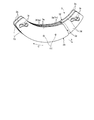
- FIG. 1 is an exemplary perspective view of the damper device according to the first embodiment.
- FIG. 2 is an exemplary perspective view of the weight member of the damper device according to the first embodiment.
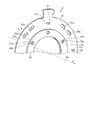
- FIG. 3 is an exemplary perspective view of a part of the rotating member of the damper device according to the first embodiment.
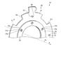
- FIG. 4 is an exemplary front view of the damper device according to the first embodiment, and shows a state in which the weight member is in a neutral position.
- FIG. 5 is an exemplary front view of the damper device according to the first embodiment, and shows a state in which the weight member is in the first position.
- FIG. 6 is an exemplary front view of the damper device according to the first embodiment, and shows a state where the weight member is in the second position.
- FIG. 7 is an exemplary perspective view of a part of the rotating member of the damper device according to the second embodiment.
- FIG. 8 is an exemplary plan view of the weight member of the damper device according to the third embodiment as viewed from the inside in the
- the damper device 1 includes, for example, a rotating member 2 and a plurality of weight members 3.
- the damper device 1 is provided, for example, between an output shaft of an engine on the input side and an input shaft of a transmission on the output side, and torque fluctuations and torsional vibrations caused by torsion between the output shaft and the input shaft. Relaxes etc.
- the damper device 1 can also be referred to as a torque fluctuation absorber.
- the damper device 1 is not limited to be provided between the engine and the transmission, but can be provided between the other two rotating elements, for example, between the engine and the motor generator. It can be provided in a vehicle or a machine having a rotating element.
- Rotating member 2 is provided so as to be rotatable about a rotation axis Ax shown in FIG.
- the rotation axis Ax is an example of a rotation center.
- the rotation axis Ax substantially coincides with the output shaft of the engine and the input shaft of the transmission.
- the axial direction indicates the axial direction of the rotational axis Ax
- the radial direction indicates the radial direction of the rotational axis Ax
- the circumferential direction indicates the circumferential direction of the rotational axis Ax.
- one side in the axial direction is indicated by an arrow X
- the outside in the radial direction is indicated by an arrow R
- one side in the circumferential direction is indicated by an arrow C.
- the rotating member 2 is formed in an annular shape around the rotation axis Ax, and has a plate shape extending in the radial direction (R direction) and the circumferential direction (C direction), that is, The normal direction is configured in a plate shape parallel to the rotation axis Ax.
- the rotating member 2 is, for example, a driven plate connected to a rotating element of the transmission.
- the rotating member 2 is not limited to the driven plate, and may be, for example, a drive plate connected to the rotating element of the engine or another rotating body that can be disposed between the engine and the transmission.
- the drive plate and the driven plate are examples of components of the damper unit included in the damper device 1.
- Each of the plurality of weight members 3 is formed in an arc shape extending along the circumferential direction, and has a plate shape extending along the radial direction (R direction) and the circumferential direction (C direction), that is, its normal direction. Is configured in a plate shape parallel to the rotation axis Ax.
- the four weight members 3 are attached to the support portion 22 of the rotating member 2 in a state where the four weight members 3 are arranged in the circumferential direction.
- the weight member 3 can also be called a mass body, an inertial body, a rocking body, a pendulum, or the like.
- the weight member 3 is an example of a component of the dynamic vibration absorber provided in the damper device 1.
- the weight member 3 swings in a pendulum shape with respect to the rotating member 2 due to the centrifugal force generated by the rotation of the rotating member 2 around the rotation axis Ax. Can be relaxed.
- the rotating member 2 includes, for example, a base portion 21, a support portion 22, and a protruding portion 23.
- the base portion 21 is configured, for example, in an annular and plate shape that intersects the rotation axis Ax and expands in the radial direction.
- the base portion 21 is provided with a plurality of openings 21a spaced from each other in the circumferential direction (C direction).
- the opening 21a is configured as, for example, a long hole extending along the circumferential direction of the rotation axis Ax.
- the coupler C1 of the weight member 3 shown in FIGS. 1 and 2 is inserted into the opening 21a.
- the opening 21a functions as a clearance hole for the coupler C1 and allows relative movement between the weight member 3 and the rotating member 2.
- openings 21b and 21c are respectively provided on the inner side in the radial direction from the opening 21a of the base portion 21 and at positions shifted in the circumferential direction from the opening 21a of the base portion 21. It has been.
- the openings 21b and 21c are, for example, through holes that penetrate the base 21 along the axial direction.
- the support portion 22 is configured by, for example, a cylindrical and bar-shaped component extending along the axial direction (X direction) of the rotation axis Ax.
- the support portion 22 can be coupled to the opening portion 21c of the base portion 21 by, for example, press-fitting or adhesion. Therefore, the support portion 22 rotates integrally with the base portion 21 around the rotation axis Ax and cannot roll with respect to the base portion 21.
- four support portions 22 are provided at equal intervals in the circumferential direction (C direction).
- the support portion 22 is attached in a state of penetrating the base portion 21 along the axial direction, and protrudes from the base portion 21 to both sides in the axial direction.
- the projecting portion 23 is constituted by, for example, an annular and plate-shaped component around the rotation axis Ax. As shown in FIG. 3, the diameter of the protruding portion 23 is smaller than the diameter of the base portion 21.
- the protrusion 23 is overlapped with the radially inner portion of the base portion 21 in the axial direction (X direction).
- the protrusion 23 is provided with a plurality of openings 23a spaced from each other in the circumferential direction (C direction).
- the base portion 21a and the protruding portion 23 can be coupled to each other by a coupling tool (not shown) that penetrates the respective opening portions 21b and 23a in the axial direction. Therefore, the protruding portion 23 rotates integrally with the base portion 21 around the rotation axis Ax.
- the protruding portion 23 has a convex curved surface 23s facing the radially inner surface 3s of the weight member 3 shown in FIGS.
- the convex curved surface 23s is a surface on the outer side in the radial direction of the protruding portion 23, and is configured, for example, in a cylindrical surface around the rotation axis Ax.
- the protrusion part 23 is comprised by soft materials, such as rubber
- the protrusion 23 is an example of a buffer member. In the present embodiment, the case where the base portion 21 and the protruding portion 23 are configured by different parts is exemplified, but the present invention is not limited to this.
- the base portion 21 and the protruding portion 23 are the same component. It may be constituted by.
- the base portion 21 and the protruding portion 23 may be made of rubber, resin, or the like, and the base portion 21 and the protruding portion 23 are made of a metal material, and the outer peripheral portion of the protruding portion 23 is A cylindrical buffer member may be attached.
- the weight member 3 includes, for example, a first weight member 31 and a second weight member 32.
- the first weight member 31 is located on one side of the base portion 21 in the axial direction (X direction)
- the second weight member 32 is on the other side of the base portion 21 in the axial direction.
- the first weight member 31 and the second weight member 32 arranged in the axial direction are coupled to each other by a coupling tool C1 such as a rivet penetrating each other in the axial direction. Therefore, the first weight member 31 and the second weight member 32 swing integrally with the rotating member 2.
- the first weight member 31 and the second weight member 32 are integrated is exemplified, but the present invention is not limited to this.
- the first weight member 31 and the second weight member 32 instead of being integrated with the weight member 32, each may swing separately with respect to the rotating member 2.
- the first weight member 31 and the second weight member 32 each have an intermediate portion 3a and two end portions 3b and 3c.
- the intermediate portion 3a is a portion of the first weight member 31 and the second weight member 32 that is located at the central portion in the circumferential direction (C direction).
- the thickness in the axial direction (X direction) of the intermediate portion 3a is configured to be thicker than the thickness in the axial direction of the two end portions 3b and 3c.
- the intermediate part 3a can also be referred to as a base part, a thick part, a connection part, an overlapping part, or the like.
- the end 3 b is a portion of the first weight member 31 and the second weight member 32 that is located on one side in the circumferential direction (C direction), and the end 3 c is the first weight member 31. And a portion of the second weight member 32 located on the other side in the circumferential direction.
- the thickness in the axial direction (X direction) of the end portion 3b and the thickness in the axial direction of the end portion 3c are substantially the same.
- the two end portions 3b and 3c extend in the opposite directions in the circumferential direction from positions shifted from each other in the axial direction of the intermediate portion 3a.
- the ends 3b and 3c can also be referred to as protrusions, overhangs, thin portions, and the like. As shown in FIGS.
- two end portions 3 b and 3 c that are offset from each other in the axial direction are provided between the intermediate portion 3 a and the two end portions 3 b and 3 c.
- a stepped portion 3d is formed that is recessed in the axial direction by the thickness of the other end portion 3b, 3c.
- a track 3r for guiding the support portion 22 is provided at each of the two end portions 3b and 3c.
- the track 3r is, for example, a long hole that extends in a curved line with a line of sight in the axial direction (X direction) and is bent in a radially convex state of the weight member 3.
- the weight member 3 is attached to the rotating member 2 with the support portion 22 penetrating the track 3r in the axial direction. As the support portion 22 relatively moves along the track 3r, the weight member 3 can swing with respect to the rotating member 2 within the longitudinal range of the track 3r.
- the first weight member 31 and the second weight member 32 are each configured by combining a plurality of parts.
- the first weight member 31 and the second weight member 32 each have a first part 33 and a second part 34.
- the first part 33 is positioned on one side of the first weight member 31 and the second weight member 32 in the axial direction (X direction), and the second part 34 is the axial direction of the first part 33. Is located on the other side.
- the first part 33 has at least an end 3b and a part of the intermediate part 3a, and the second part 34 has at least an end 3c and a part of the intermediate part 3a.
- the first component 33 and the second component 34 are the same component. That is, the shape of the first component 33 is the same as the shape of the second component 34, and the specification of the first component 33 is the same as the specification of the second component 34.
- the first component 33 and the second component 34 are each configured in an arc shape and a plate shape extending along the circumferential direction (C direction). Further, a track 3r is provided at one end portion 3b, 3c in the circumferential direction of each of the first component 33 and the second component 34.
- the first weight member 31 and the second weight member 32 are respectively in a state where the first part 33 and the second part 34 are turned upside down, that is, in the first part 33.
- the track 3r is positioned on one side in the circumferential direction
- the track 3r of the second component 34 is positioned on the other side in the circumferential direction.
- the first component 33 and the second component 34 are arranged to be shifted from each other in the circumferential direction (C direction) and partially overlap in the axial direction (X direction).
- the intermediate portion 3a is configured by a portion where the first component 33 and the second component 34 overlap in the axial direction, and the first component 33 and the second component 34 overlap in the axial direction.
- the two end portions 3b and 3c are constituted by the portions that are not present.
- the weight member 3 for example, two tracks 3 r provided at the respective end portions 3 b of the first weight member 31 and the second weight member 32 overlap each other in the axial direction (X direction), and the first The two orbits 3r provided at the respective end portions 3c of the weight member 31 and the second weight member 32 are integrated by the coupler C1 in a state where they overlap each other in the axial direction.
- the weight member 3 is attached to the rotating member 2 with the support portion 22 penetrating through the two tracks 3r of the first weight member 31 and the second weight member 32 in the axial direction.
- one end 3 b of two weight members 3 adjacent in the circumferential direction (C direction) and the other end of the two weight members 3. 3c are arranged so as to overlap each other in the axial direction (X direction).
- the support portion 22 is shared by the two tracks 3 r provided on the two end portions 3 b and 3 c that overlap each other. If the number of supporting portions 22 corresponding to the respective tracks 3r of the weight members 3 is attached to the rotating member 2, the number of parts of the damper device 1 may increase.
- the support portions 22 can be shared by the tracks 3r provided on the respective weight members 3, the number of the support portions 22, and thus the number of parts of the damper device 1 can be easily reduced. Become. Therefore, for example, the labor and cost required for manufacturing the damper device 1 are likely to be reduced.
- an end 3 b thinner than one intermediate portion 3 a among two adjacent weight members 3 is positioned on one side in the axial direction, and the two weight members 3
- the intermediate part 3a of the some weight member 3 can be arranged in the circumferential direction in the state without a level
- the damper device 1 may be increased in size in the axial direction.
- the configuration and arrangement of the intermediate portion 3a and the end portions 3b and 3c described above prevent the damper device 1 from being enlarged in the axial direction.
- the radially inner surface 3s of the weight member 3 has two concave curved surfaces 3f and 3g.
- the two concave curved surfaces 3f and 3g are positioned so as to be shifted from each other in the circumferential direction (C direction), and each has a shape that can follow the convex curved surface 23s of the protruding portion 23.
- the two concave curved surfaces 3f and 3g can contact the convex curved surface 23s from the outside in the radial direction of the rotation axis Ax.
- the weight member 3 has a first position P1 shown in FIG. 5, a second position P2 shown in FIG. 6, and a neutral position P0 shown in FIG. , And is configured to be swingable between.
- the concave curved surface 3g of the weight member 3 and the convex curved surface 23s of the protruding portion 23 come into contact with each other.
- the contact of the concave curved surface 3g and the convex curved surface 23s restricts the movement of the weight member 3 to one side along the track 3r with respect to the rotating member 2.
- the first position P1 can also be referred to as a first limit position or the like.
- the support portion 22 faces the edge portion on one side in the longitudinal direction of the track 3r with a slight gap. That is, the contact of the concave curved surface 3g and the convex curved surface 23s restricts the movement of the support portion 22 to one side along the longitudinal direction of the track 3r.
- the concave curved surface 3f of the weight member 3 and the convex curved surface 23s of the protruding portion 23 come into contact with each other. Due to the contact between the concave curved surface 3f and the convex curved surface 23s, the movement of the weight member 3 to the other side along the track 3r with respect to the rotating member 2 is limited.
- the second position P2 can also be referred to as a second restriction position.
- the support portion 22 faces the other edge portion in the longitudinal direction of the track 3r with a slight gap. That is, the contact of the concave curved surface 3f and the convex curved surface 23s restricts the movement of the support portion 22 to the other side along the longitudinal direction of the track 3r.
- the two concave curved surfaces 3f and 3g of the weight member 3 and the convex curved surface 23s of the protruding portion 23 are separated from each other. Therefore, in the neutral position P0, the movement of the weight member 3 to the one side and the other side along the track 3r with respect to the rotating member 2, that is, the movement of the support portion 22 to the one side and the other side along the track 3r is allowed.
- the two concave curved surfaces 3f and 3g and the convex curved surface 23s are an example of a stopper mechanism.
- the movement range along the longitudinal direction of the track 3r of the support portion 22 is limited by the two concave curved surfaces 3f and 3g and the convex curved surface 23s. Therefore, according to the present embodiment, for example, the contact between the support portion 22 and the edge of the track 3r is easily suppressed, and as a result, the hitting sound or wear caused by the contact between the support portion 22 and the edge of the track 3r is generated. Can be suppressed.
- the concave curved surface 3g and the convex curved surface 23s are in contact with each other while the weight member 3 is in the first position P1, and the concave curved surface. 3f and the convex curved surface 23s are in contact with each other in a state along which the weight member 3 is located at the second position P2. Therefore, according to the present embodiment, for example, the concave curved surfaces 3f and 3g and the convex curved surface 23s come into contact with each other over a relatively large area, so that the surface pressure is easily lowered, and consequently the concave curved surfaces 3f and 3g and the convex curved surface 23s The hitting sound and wear caused by the contact can be suppressed.
- the projecting portion 23 is configured by a cushioning member such as rubber or resin, it is easy to further suppress the hitting sound, wear, etc. caused by the contact between the concave curved surfaces 3f and 3g and the convex curved surface 23s.
- the protruding portion 23, that is, the buffer member is provided on the rotating member 2 side is illustrated, but the present invention is not limited thereto, and may be provided on the weight member 3 side, for example.
- the weight member 3 may be configured by a buffer member, or an arc-shaped buffer member may be attached to the inner peripheral portion of the weight member 3. As shown in FIGS.
- the case where the protruding portion 23 is provided only on one side in the axial direction of the base portion 21 is exemplified, but the present invention is not limited to this, and the axial direction It may be provided on both sides.
- the damper device 1 is configured to be rotatable around the rotation axis Ax (rotation center), and has a plate-like base portion 21 and the rotation shaft Ax attached to the base portion 21.
- the rotating member 2 having a support portion 22 extending in the axial direction (X direction) of the rotating member 2 and the rotating member 2 are disposed so as to partially overlap each other in the axial direction.
- a plurality of weight members 3 provided with tracks 3r for guiding the support portion 22 so as to be swingable.
- the support portions 22 are shared by the tracks 3r provided on each of the plurality of weight members 3.
- the number of the support portions 22, and hence the dampers are compared with the case where the number of support portions 22 corresponding to the track 3 r of each weight member 3 is attached to the base portion 21 of the rotating member 2.
- the number of parts of the device 1 is likely to be reduced. Therefore, for example, the labor and cost required for manufacturing the damper device 1 are likely to be reduced.
- the plurality of weight members 3 are arranged to be shifted from each other in the circumferential direction (C direction) of the rotation axis Ax, and the support portion 22 is provided on two weight members 3 adjacent in the circumferential direction.
- Each track 3r is shared. That is, in the present embodiment, two first weight members 31 that are shifted in the circumferential direction on the one side in the axial direction (X direction) of the base portion 21 and the first on the other side in the axial direction of the base portion 21.
- Each of the weight members 31 and the two second weight members 32 that are arranged in the axial direction and are offset from each other in the circumferential direction share the support portion 22.
- the damper apparatus 1 which can share the support part 22 can be implement
- the case where the plurality of weight members 3 are displaced from each other in the circumferential direction is illustrated, but the present invention is not limited to this.
- the plurality of weight members 3 are displaced from each other in the radial direction (R direction).
- the support 22 may be shared depending on the configuration.
- the plurality of weight members 3 include the intermediate portion 3a positioned on one side of the base portion 21 in the axial direction (X direction), and each is thinner than the axial thickness of the intermediate portion 3a. And two end portions 3b and 3c each extending in one and the other in the circumferential direction (C direction) from a position shifted from each other in the axial direction of the intermediate portion 3a.
- One end 3b in one circumferential direction and the other end 3c in the other circumferential direction of the two weight members 3 overlap each other in the axial direction. Therefore, according to the present embodiment, for example, compared to a case where two weight members 3 having a constant axial thickness overlap each other in the axial direction, the damper device 1 is easily suppressed from being enlarged in the axial direction. .
- the plurality of weight members 3 includes a first part 33 that constitutes a part of the intermediate portion 3a and one end portion 3b in the circumferential direction (C direction), and the intermediate portion 3a.
- the first component 33 includes a first component 33 and a second component 34 partially overlapping with each other in the axial direction (X direction).
- the second part 34 have the same shape. Therefore, according to the present embodiment, for example, the configuration of the weight member 3 having the two end portions 3b and 3c and the intermediate portion 3a that are offset from each other in the axial direction can be obtained relatively easily or at a lower cost. .
- the rotating member 2 has a protruding portion 23 that protrudes from the base portion 21 and has a cylindrical curved surface 23 s around the rotation axis Ax, and at least one of the plurality of weight members 3.
- One has concave curved surfaces 3f and 3g that can come into contact with the convex curved surface 23s along the convex curved surface 23s from the outside in the radial direction of the rotation axis Ax, and the convex curved surface 23s and the concave curved surfaces 3f and 3g are along each other.
- contact between the convex curved surface 23s and the concave curved surfaces 3f and 3g in the region along the circumferential direction can easily suppress contact between the support portion 22 and the edge of the track 3r.
- At least one of the plurality of weight members 3 has two concave curved surfaces 3f and 3g that are shifted from each other in the circumferential direction (C direction).
- the movement of the support portion 22 to one side along the track 3r is restricted by the contact with the curved surface 3f, and the movement of the support portion 22 to the other along the track 3r is restricted by the contact of the convex curved surface 23s and the concave curved surface 3g. Limited. Therefore, according to the present embodiment, for example, the contact between the two concave curved surfaces 3f and 3g and the convex curved surface 23s can further suppress the contact between the support portion 22 and the edge of the track 3r.
- the plurality of weight members 3 have concave curved surfaces 3f and 3g, respectively, and the convex curved surface 23s is shared by the concave curved surfaces 3f and 3g provided on each of the plurality of weight members 3.
- the convex curved surface 23s corresponding to the concave curved surface 3f, 3g of each weight member 3 is provided in the rotating member 2, for example, the protrusion 23 and the rotating member 2 are simpler. It is easy to be configured with a simple shape. Therefore, for example, the labor and cost required for manufacturing the damper device 1 are likely to be reduced.
- the damper device 1A of the embodiment shown in FIG. 7 has the same configuration as the damper device 1 of the first embodiment. Therefore, also according to this embodiment, the same result (effect) based on the same configuration as that of the first embodiment can be obtained.
- the base portion 21 of the rotating member 2 ⁇ / b> A is provided with a plurality of openings 21 r spaced from each other in the circumferential direction (C direction).
- the opening 21r is configured as, for example, a notch that opens toward the outside in the radial direction of the base 21.
- the opening 21r penetrates the base portion 21 along the axial direction (X direction) and extends along the circumferential direction.
- the coupler C1 of the weight member 3 shown in FIGS. 1 and 2 is inserted into the opening 21r.
- the opening 21r is shared as a relief hole for the plurality of couplers C1.
- the base portion 21 and thus the rotating member 2A have a simpler shape than the case where the base portion 21 is provided with a number of relief holes corresponding to the plurality of couplers C1. Easy to be configured. Therefore, for example, the labor and cost required for manufacturing the damper device 1A are likely to be reduced.
- the damper device 1B of the embodiment shown in FIG. 8 has the same configuration as the damper device 1 of the first embodiment. Therefore, also according to this embodiment, the same result (effect) based on the same configuration as that of the first embodiment can be obtained.
- the first component 33 is more than the second component 34.
- the second weight member 32A which is also located on the other side in the axial direction and located on the other side in the axial direction, the first part 33 is located on one side in the axial direction with respect to the second part 34. . That is, in the weight member 3A, the axial arrangement of the first component 33 and the second component 34 in the first weight member 31A and the first component 33 and the second component 34 in the second weight member 32A.
- the first weight member 31A and the second weight member 32A are integrated by the coupler C1 in a state where the arrangement in the axial direction is opposite to each other.
- the first part 33 and the second part 34 of the first weight member 31A and the second weight member 32A are rotated orthogonally to the rotation axis Ax. It can arrange
- FIG. therefore, according to the present embodiment, for example, the center of gravity of the first weight member 31 ⁇ / b> A and the second weight member 32 ⁇ / b> A can be arranged closer to the central portion of the base portion 21 in the axial direction.
- the first weight member 31A and the second weight member 32A in which the first component 33 and the second component 34 are stacked in the opposite arrangement in the axial direction, are connected by the coupler C1. Since they are integrated, a change in the position of the center of gravity of the weight member 3A is suppressed, and therefore vibration due to rotation of the damper device 1B is less likely to occur. Note that the first weight member 31A and the second weight member 32A may not be integrated by the coupler C1.
Landscapes
- Engineering & Computer Science (AREA)
- General Engineering & Computer Science (AREA)
- Physics & Mathematics (AREA)
- Acoustics & Sound (AREA)
- Aviation & Aerospace Engineering (AREA)
- Mechanical Engineering (AREA)
- Fluid-Damping Devices (AREA)
- Vibration Prevention Devices (AREA)
- Vibration Dampers (AREA)
Abstract
実施形態のダンパ装置(1)は、例えば、回転軸回りに回転可能に構成され、板状のベース部(21)と、当該ベース部(21)に取り付けられ回転軸の軸方向に沿って延びた支持部(22)と、を有した回転部材(2)と、軸方向に互いに部分的に重なり合って配置され、当該重なり合った部分のそれぞれに回転部材(2)に対して揺動可能となるように支持部(22)を案内する軌道(3r)が設けられた複数の錘部材(3)と、を備え、支持部(22)は、複数の錘部材(3)のそれぞれに設けられた軌道(3r)で共用される。
Description
本発明の実施形態は、ダンパ装置に関する。
従来、それぞれに軌道が設けられた複数の錘部材と、各錘部材の軌道に対応した数の支持部が取り付けられた回転部材と、を備えたダンパ装置が、知られている。
この種のダンパ装置では、例えば、製造に要する手間や費用が低減されやすい新規な構成が得られれば、好ましい。
実施形態のダンパ装置は、例えば、回転中心回りに回転可能に構成され、板状のベース部と、当該ベース部に取り付けられ上記回転中心の軸方向に沿って延びた支持部と、を有した回転部材と、上記軸方向に互いに部分的に重なり合って配置され、当該重なり合った部分のそれぞれに上記回転部材に対して揺動可能となるように上記支持部を案内する軌道が設けられた複数の錘部材と、を備え、上記支持部は、上記複数の錘部材のそれぞれに設けられた上記軌道で共用される。よって、例えば、回転部材に各錘部材の軌道に対応した数の支持部が取り付けられる場合と比べて、支持部の数、ひいてはダンパ装置の部品点数が減りやすい。よって、例えば、ダンパ装置の製造に要する手間や費用が低減されやすい。
また、上記ダンパ装置では、例えば、上記複数の錘部材は、上記回転中心の周方向に互いにずれて配置され、上記支持部は、上記周方向に隣接した二つの上記錘部材に設けられたそれぞれの上記軌道で共用される。よって、例えば、複数の錘部材が周方向に互いにずれた構成によって、支持部を共用可能なダンパ装置が実現されうる。
また、上記ダンパ装置では、例えば、上記複数の錘部材は、上記ベース部の上記軸方向の一方に位置された中間部と、それぞれが上記中間部の上記軸方向の厚さよりも薄く構成され、上記中間部の上記軸方向に互いにずれた位置から上記周方向の一方および他方に延びた二つの端部と、をそれぞれ有し、上記二つの錘部材のうち一つの上記周方向の一方の上記端部と、上記二つの錘部材のうちもう一つの上記周方向の他方の上記端部とが、上記軸方向に互いに重なり合う。よって、例えば、軸方向の厚さが一定の二つの錘部材が軸方向に互いに重なり合う場合に比べて、ダンパ装置が軸方向に大型化するのが抑制されやすい。
また、上記ダンパ装置では、例えば、上記複数の錘部材は、上記中間部の一部と上記周方向の一方の上記端部とを構成する第一の部品と、上記中間部の一部と上記周方向の他方の上記端部とを構成し上記第一の部品と上記軸方向に部分的に重なった第二の部品と、をそれぞれ有し、上記第一の部品と上記第二の部品とが、同一形状を有する。よって、例えば、軸方向に互いにずれた二つの端部と中間部とを有した錘部材の構成が、比較的容易にあるいはより安価に得られやすい。
また、上記ダンパ装置では、例えば、上記複数の錘部材は、上記ベース部の上記軸方向の一方で上記周方向に互いにずれて配置された複数の第一の錘部材と、上記ベース部の上記軸方向の他方で上記複数の第一の錘部材のそれぞれと上記軸方向に並ぶとともに上記周方向に互いにずれて配置された複数の第二の錘部材と、を有し、上記軸方向に並ぶ上記第一の錘部材と上記第二の錘部材とにおいては、上記第一の錘部材における上記第一の部品および上記第二の部品の上記軸方向の配列と、上記第二の錘部材における上記第一の部品および上記第二の部品の上記軸方向の配列とが、互いに逆である。よって、例えば、第一の部品と第二の部品とが軸方向に互いに逆の配列で重ねられた構成によって、第一の錘部材および第二の錘部材の重心がベース部の軸方向の中央部により近づいて配置されうる。よって、例えば、ダンパ装置の回転に伴う振動がより生じ難くなる。
また、上記ダンパ装置では、例えば、上記回転部材は、上記ベース部から突出し上記回転中心回りの円筒面状の凸曲面を有した突出部を有し、上記複数の錘部材のうち少なくとも一つは、上記凸曲面に沿って当該凸曲面と上記回転中心の径方向の外方から当接可能な凹曲面を有し、上記凸曲面と上記凹曲面とが互いに沿う状態で当接することにより、上記支持部の上記軌道に沿う移動範囲が制限される。よって、例えば、凸曲面と凹曲面との周方向に沿った領域での当接によって、支持部と軌道の縁部との接触が抑制されやすくなり、ひいては支持部と軌道の縁部との接触によって生じる打音や摩耗等が抑制されうる。
また、上記ダンパ装置では、例えば、上記複数の錘部材のうち少なくとも一つは、上記回転中心の周方向に互いにずれて位置された二つの上記凹曲面を有し、上記凸曲面と上記二つの凹曲面のうち一つとの当接によって、上記支持部の上記軌道に沿う一方への移動が制限され、上記凸曲面と上記二つの凹曲面のうちもう一つとの当接によって、上記支持部の上記軌道に沿う他方への移動が制限される。よって、例えば、二つの凹曲面と凸曲面との当接によって、支持部と軌道の縁部との接触がより一層抑制されうる。
また、上記ダンパ装置では、例えば、上記複数の錘部材は、それぞれが上記凹曲面を有し、上記凸曲面は、上記複数の錘部材のそれぞれに設けられた上記凹曲面で共用される。よって、例えば、回転部材に各錘部材の凹曲面に対応した凸曲面が設けられる場合と比べて、突出部、ひいては回転部材がより簡素な形状で構成されやすい。よって、例えば、ダンパ装置の製造に要する手間や費用が低減されやすい。
以下、本発明の例示的な実施形態が開示される。以下に示される実施形態の構成、ならびに当該構成によってもたらされる作用、結果、および効果は、あくまで一例である。本発明は、以下の実施形態に開示される構成以外によっても実現可能である。また、本発明によれば、構成によって得られる種々の効果のうち少なくとも一つを得ることが可能である。
また、以下に開示される複数の実施形態には、同様の構成要素が含まれる。よって、以下では、それら同様の構成要素には共通の符号が付与されるとともに、重複する説明が省略される。
<第1実施形態>
図1に示されるように、ダンパ装置1は、例えば、回転部材2と、複数の錘部材3と、を備える。ダンパ装置1は、例えば、入力側となるエンジンの出力軸と、出力側となるトランスミッションの入力軸との間に設けられ、これら出力軸と入力軸との間の捩れによって生じるトルク変動や捩り振動等を緩和する。ダンパ装置1は、トルク変動吸収装置とも称されうる。なお、ダンパ装置1は、エンジンとトランスミッションとの間には限らず、他の二つの回転要素間、例えば、エンジンとモータジェネレータとの間に設けることが可能であるし、ハイブリッド自動車等の種々の車両や、回転要素を有した機械等に設けることが可能である。
図1に示されるように、ダンパ装置1は、例えば、回転部材2と、複数の錘部材3と、を備える。ダンパ装置1は、例えば、入力側となるエンジンの出力軸と、出力側となるトランスミッションの入力軸との間に設けられ、これら出力軸と入力軸との間の捩れによって生じるトルク変動や捩り振動等を緩和する。ダンパ装置1は、トルク変動吸収装置とも称されうる。なお、ダンパ装置1は、エンジンとトランスミッションとの間には限らず、他の二つの回転要素間、例えば、エンジンとモータジェネレータとの間に設けることが可能であるし、ハイブリッド自動車等の種々の車両や、回転要素を有した機械等に設けることが可能である。
回転部材2は、図1に示される回転軸Ax回りに回転可能に設けられている。回転軸Axは、回転中心の一例である。回転軸Axは、例えば、エンジンの出力軸およびトランスミッションの入力軸と略一致している。なお、以下の説明では、軸方向は回転軸Axの軸方向、径方向は回転軸Axの径方向、周方向は回転軸Axの周方向を示す。また、図中、軸方向の一方側を矢印Xで示し、径方向の外側を矢印Rで示し、周方向の一方側を矢印Cで示す。
図1,4に示されるように、回転部材2は、回転軸Ax回りの円環状に構成されるとともに、径方向(R方向)および周方向(C方向)に沿って広がった板状、すなわちその法線方向が回転軸Axと平行な板状に、構成されている。回転部材2は、例えば、トランスミッションの回転要素と接続されるドリブンプレートである。なお、回転部材2は、ドリブンプレートに限らず、例えば、エンジンの回転要素と接続されるドライブプレートや、エンジンとトランスミッションとの間に配置されうるその他の回転体でもよい。ドライブプレート、およびドリブンプレートは、ダンパ装置1が備えるダンパ部の構成要素の一例である。
複数の錘部材3は、それぞれが周方向に沿って延びた円弧状に構成されるとともに、径方向(R方向)および周方向(C方向)に沿って広がった板状、すなわちその法線方向が回転軸Axと平行な板状に、構成されている。本実施形態では、例えば、四つの錘部材3が周方向に並べられた状態で、回転部材2の支持部22に取り付けられている。錘部材3は、質量体や、慣性体、揺動体、振り子等とも称されうる。錘部材3は、ダンパ装置1が備える動吸振器の構成要素の一例である。動吸振器としてのダイナミックダンパ部では、例えば、回転部材2の回転軸Ax回りの回転によって生じる遠心力によって、錘部材3が回転部材2に対して振り子状に揺動することにより、捩り振動を緩和することができる。
図3に示されるように、回転部材2は、例えば、ベース部21と、支持部22と、突出部23と、を有する。ベース部21は、例えば、回転軸Axと交差して径方向に広がった円環状かつ板状に構成されている。ベース部21には、周方向(C方向)に互いに間隔をあけて複数の開口部21aが設けられている。開口部21aは、例えば、回転軸Axの周方向に沿って延びた長穴として構成されている。開口部21aには、図1,2に示される錘部材3の結合具C1が挿入される。開口部21aは、例えば、結合具C1の逃げ穴として機能し、錘部材3と回転部材2との相対移動を許容している。また、図3に示されるように、ベース部21の開口部21aよりも径方向の内側、およびベース部21の開口部21aと周方向にずれた位置には、それぞれ開口部21b,21cが設けられている。開口部21b,21cは、例えば、ベース部21を軸方向に沿って貫通した貫通孔である。
支持部22は、例えば、回転軸Axの軸方向(X方向)に沿って延びた円柱状かつ棒状の部品によって構成されている。支持部22は、ベース部21の開口部21cに、例えば、圧入や、接着等によって結合されうる。よって、支持部22は、ベース部21と回転軸Ax回りに一体に回転するとともに、ベース部21に対して転動不能である。図1に示されるように、本実施形態では、例えば、四つの支持部22が周方向(C方向)に互いに等間隔で設けられている。支持部22は、ベース部21を軸方向に沿って貫通した状態で取り付けられ、ベース部21から軸方向の両側に突出している。
突出部23は、例えば、回転軸Ax回りの円環状かつ板状の部品によって構成されている。図3に示されるように、突出部23の直径は、ベース部21の直径よりも小さい。そして、突出部23は、ベース部21の径方向の内側の部分と軸方向(X方向)に重ねられている。また、突出部23には、周方向(C方向)に互いに間隔をあけて複数の開口部23aが設けられている。ベース部21aと突出部23とは、それぞれの開口部21b,23aを軸方向に貫通する不図示の結合具によって互いに結合されうる。よって、突出部23は、ベース部21と回転軸Ax回りに一体に回転する。
また、突出部23は、図1,2に示される錘部材3の径方向の内側の面3sと面する凸曲面23sを有する。凸曲面23sは、突出部23の径方向の外側の面であり、例えば、回転軸Ax回りの円筒面状に構成されている。また、本実施形態では、突出部23は、例えば、ゴムや樹脂等の軟質材料によって構成されている。突出部23は、緩衝部材の一例である。なお、本実施形態では、ベース部21と突出部23とがそれぞれ別の部品で構成された場合が例示されたが、これに限定されず、例えば、ベース部21と突出部23とが同じ部品で構成されてもよい。この場合、例えば、ベース部21と突出部23とがゴムや樹脂等で構成されてもよいし、ベース部21と突出部23とが金属材料で構成されるとともに、突出部23の外周部に円筒状の緩衝部材が取り付けられてもよい。
図2に示されるように、錘部材3は、例えば、第一の錘部材31と、第二の錘部材32と、を有する。図1にも示されるように、第一の錘部材31は、ベース部21の軸方向(X方向)の一方側に位置され、第二の錘部材32は、ベース部21の軸方向の他方側に位置されている。軸方向に並んだ第一の錘部材31と第二の錘部材32とは、それぞれを軸方向に貫通したリベット等の結合具C1によって、互いに結合されている。よって、第一の錘部材31と第二の錘部材32とは、回転部材2に対して一体に揺動する。なお、本実施形態では、第一の錘部材31と第二の錘部材32とが一体化された場合が例示されたが、これに限定されず、例えば、第一の錘部材31と第二の錘部材32とが一体化されずに、それぞれが別々に回転部材2に対して揺動してもよい。
図2に示されるように、第一の錘部材31および第二の錘部材32は、それぞれ、中間部3aと、二つの端部3b,3cと、を有する。中間部3aは、第一の錘部材31および第二の錘部材32のうち周方向(C方向)の中央部に位置された部分である。図1にも示されるように、本実施形態では、中間部3aの軸方向(X方向)の厚さは、二つの端部3b,3cの軸方向の厚さよりも厚く構成されている。中間部3aは、基部や、厚肉部、接続部、重なり部等とも称されうる。
また、端部3bは、第一の錘部材31および第二の錘部材32のうち周方向(C方向)の一方側に位置された部分であり、端部3cは、第一の錘部材31および第二の錘部材32のうち周方向の他方側に位置された部分である。本実施形態では、端部3bの軸方向(X方向)の厚さ、および端部3cの軸方向の厚さは、略同じである。二つの端部3b,3cは、中間部3aの軸方向に互いにずれた位置から、周方向の互いに反対方向に延びている。端部3b,3cは、突出部や、張出部、薄肉部等とも称されうる。図1,2に示されるように、本実施形態では、軸方向に互いにずれた二つの端部3b,3cによって、中間部3aと二つの端部3b,3cとのそれぞれの間には、二つの端部3b,3cのうち他方の厚さ分だけ軸方向に凹んだ段差部3dが形成されている。
また、図2に示されるように、本実施形態では、二つの端部3b,3cのそれぞれに、支持部22を案内する軌道3rが設けられている。軌道3rは、例えば、軸方向(X方向)の視線で曲線状に延びるとともに錘部材3の径方向の内側に凸の状態で曲がった長穴である。図1に示されるように、錘部材3は、支持部22が軌道3rを軸方向に貫通した状態で、回転部材2に取り付けられる。支持部22が軌道3rに沿って相対的に移動することにより、錘部材3は、軌道3rの長手方向の範囲内で回転部材2に対して揺動可能となる。
また、図2に示されるように、本実施形態では、第一の錘部材31および第二の錘部材32は、それぞれ、複数の部品が組み合わせられて構成されている。具体的には、第一の錘部材31および第二の錘部材32は、それぞれ、第一の部品33と、第二の部品34と、を有する。第一の部品33は、第一の錘部材31および第二の錘部材32のうち軸方向(X方向)の一方側に位置され、第二の部品34は、第一の部品33の軸方向の他方側に位置されている。第一の部品33は、少なくとも、端部3bと中間部3aの一部とを有し、第二の部品34は、少なくとも、端部3cと中間部3aの一部とを有する。
また、本実施形態では、例えば、第一の部品33と第二の部品34とは、互いに同一の部品である。すなわち、第一の部品33の形状は、第二の部品34の形状と同一であり、第一の部品33の仕様は、第二の部品34の仕様と同一である。本実施形態では、第一の部品33および第二の部品34は、それぞれ、周方向(C方向)に沿って延びた円弧状かつ板状に構成されている。また、第一の部品33および第二の部品34のそれぞれの周方向の一方側の端部3b,3cに、軌道3rが設けられている。
図2に示されるように、第一の錘部材31および第二の錘部材32は、それぞれ、第一の部品33と第二の部品34とを互いに裏返した状態、すなわち第一の部品33の軌道3rが周方向の一方側に位置され第二の部品34の軌道3rが周方向の他方側に位置された状態で、軸方向に重ねられている。また、第一の部品33と第二の部品34とは、周方向(C方向)に互いにずれて配置され、軸方向(X方向)に部分的に重なり合っている。本実施形態では、第一の部品33と第二の部品34とが軸方向に重なり合った部分によって中間部3aが構成され、第一の部品33と第二の部品34とが軸方向に重なり合わない部分によって二つの端部3b,3cが構成されている。
また、錘部材3では、例えば、第一の錘部材31および第二の錘部材32のそれぞれの端部3bに設けられた二つの軌道3rが軸方向(X方向)に互いに重なり合うとともに、第一の錘部材31および第二の錘部材32のそれぞれの端部3cに設けられた二つの軌道3rが軸方向に互いに重なり合った状態で、結合具C1によって一体化されている。本実施形態では、支持部22がこれら第一の錘部材31および第二の錘部材32の二つの軌道3rを軸方向に貫通した状態で、錘部材3が回転部材2に取り付けられている。
また、図1に示されるように、本実施形態では、周方向(C方向)に隣接した二つの錘部材3のうち一つの端部3bと、二つの錘部材3のうちもう一つの端部3cとが軸方向(X方向)に互いに重なり合って配置されている。そして、図4にも示されるように、本実施形態では、互いに重なり合った二つの端部3b,3cのそれぞれに設けられた二つの軌道3rで、支持部22が共用されている。仮に、回転部材2に各錘部材3のそれぞれの軌道3rに対応した数の支持部22が取り付けられた場合、ダンパ装置1の部品点数が増えてしまう虞がある。その点、本実施形態によれば、支持部22を各錘部材3のそれぞれに設けられた軌道3rで共用することができるため、支持部22の数、ひいてはダンパ装置1の部品点数が減りやすくなる。よって、例えば、ダンパ装置1の製造に要する手間や費用が低減されやすい。
また、図1に示されるように、本実施形態では、隣接した二つの錘部材3のうち一つの中間部3aよりも薄い端部3bが軸方向の一方に位置され、二つの錘部材3のうちもう一つの中間部3aよりも薄い端部3cが軸方向の他方に位置された状態で、端部3bと端部3cとが軸方向に互いに重なり合っている。これにより、複数の錘部材3の中間部3aが、段差の無い状態、あるいは段差の小さい状態で、周方向に並ぶことができる。仮に、軸方向の厚さが一定の二つの錘部材3が軸方向に互いに重なり合って配置された場合、ダンパ装置1が軸方向に大型化してしまう虞がある。その点、本実施形態によれば、上述した中間部3aと端部3b,3cとの構成および配置によって、ダンパ装置1が軸方向に大型化するのが抑制される。
また、図2に示されるように、本実施形態では、錘部材3の径方向の内側の面3sは、二つの凹曲面3f,3gを有している。二つの凹曲面3f,3gは、周方向(C方向)に互いにずれて位置され、それぞれが突出部23の凸曲面23sに沿うことが可能な形状に構成されている。二つの凹曲面3f,3gは、回転軸Axの径方向の外側から凸曲面23sに当接可能である。本実施形態では、錘部材3は、回転部材2に対して、図5に示される第一の位置P1と、図6に示される第二の位置P2と、図4に示される中立位置P0と、の間で揺動可能に構成されている。
図5に示されるように、錘部材3が第一の位置P1にある状態では、錘部材3の凹曲面3gと突出部23の凸曲面23sとが互いに沿う状態で当接する。凹曲面3gと凸曲面23sとの当接によって、錘部材3の回転部材2に対する軌道3rに沿う一方側への移動が制限される。第一の位置P1は、第一の制限位置等とも称されうる。また、錘部材3が第一の位置P1にある状態では、支持部22は、軌道3rの長手方向の一方側の縁部と僅かな隙間をあけて対向する。すなわち、凹曲面3gと凸曲面23sとの当接によって、支持部22の軌道3rの長手方向に沿う一方側への移動が制限されている。
また、図6に示されるように、錘部材3が第二の位置P2にある状態では、錘部材3の凹曲面3fと突出部23の凸曲面23sとが互いに沿う状態で当接する。凹曲面3fと凸曲面23sとの当接によって、錘部材3の回転部材2に対する軌道3rに沿う他方側への移動が制限される。第二の位置P2は、第二の制限位置等とも称されうる。また、錘部材3が第二の位置P2にある状態では、支持部22は、軌道3rの長手方向の他方側の縁部と僅かな隙間をあけて対向する。すなわち、凹曲面3fと凸曲面23sとの当接によって、支持部22の軌道3rの長手方向に沿う他方側への移動が制限されている。
また、図4に示されるように、錘部材3が中立位置P0にある状態では、錘部材3の二つの凹曲面3f,3gと突出部23の凸曲面23sとが互いに離間する。よって、中立位置P0では、錘部材3の回転部材2に対する軌道3rに沿う一方側および他方側への移動、すなわち支持部22の軌道3rに沿う一方側および他方側への移動が許容される。二つの凹曲面3f、3gと凸曲面23sとは、ストッパ機構の一例である。このように、本実施形態では、二つの凹曲面3f,3gと凸曲面23sとによって、支持部22の軌道3rの長手方向に沿う移動範囲が制限されている。よって、本実施形態によれば、例えば、支持部22と軌道3rの縁部との接触が抑制されやすくなり、ひいては支持部22と軌道3rの縁部との接触によって生じる打音や摩耗等が抑制されうる。
また、図5,6に示されるように、本実施形態では、凹曲面3gと凸曲面23sとは、錘部材3が第一の位置P1にある状態で、互いに沿う状態で当接し、凹曲面3fと凸曲面23sとは、錘部材3が第二の位置P2にある状態で、互いに沿う状態で当接する。よって、本実施形態によれば、例えば、凹曲面3f,3gと凸曲面23sとが比較的広い面積で当接するため、面圧が下がりやすくなり、ひいては凹曲面3f,3gと凸曲面23sとの接触によって生じる打音や摩耗等が抑制されうる。また、本実施形態では、突出部23がゴムや樹脂等の緩衝部材によって構成されているため、凹曲面3f,3gと凸曲面23sとの接触によって生じる打音や摩耗等がより一層抑制されやすくなる。なお、本実施形態では、突出部23、すなわち緩衝部材が回転部材2側に設けられた場合が例示されたが、これに限定されず、例えば、錘部材3側に設けられてもよい。この場合、例えば、錘部材3が緩衝部材で構成されてもよいし、錘部材3の内周部に円弧状の緩衝部材が取り付けられてもよい。また、図1,3に示されるように、本実施形態では、突出部23がベース部21の軸方向の一方側のみに設けられた場合が例示されたが、これに限定されず、軸方向の両側に設けられてもよい。
以上のように、本実施形態では、例えば、ダンパ装置1は、回転軸Ax(回転中心)回りに回転可能に構成され、板状のベース部21と、当該ベース部21に取り付けられ回転軸Axの軸方向(X方向)に沿って延びた支持部22と、を有した回転部材2と、軸方向に互いに部分的に重なり合って配置され、当該重なり合った部分のそれぞれに回転部材2に対して揺動可能となるように支持部22を案内する軌道3rが設けられた複数の錘部材3と、を備え、支持部22は、複数の錘部材3のそれぞれに設けられた軌道3rで共用される。よって、本実施形態によれば、例えば、回転部材2のベース部21に各錘部材3の軌道3rに対応した数の支持部22が取り付けられる場合と比べて、支持部22の数、ひいてはダンパ装置1の部品点数が減りやすい。よって、例えば、ダンパ装置1の製造に要する手間や費用が低減されやすい。
また、本実施形態では、例えば、複数の錘部材3は、回転軸Axの周方向(C方向)に互いにずれて配置され、支持部22は、周方向に隣接した二つの錘部材3に設けられたそれぞれの軌道3rで共用される。すなわち、本実施形態では、ベース部21の軸方向(X方向)の一方で周方向に互いにずれて配置された二つの第一の錘部材31と、ベース部21の軸方向の他方で第一の錘部材31のそれぞれと軸方向に並ぶとともに周方向に互いにずれて配置された二つの第二の錘部材32とで支持部22が共用されている。よって、本実施形態によれば、例えば、複数の錘部材3が周方向に互いにずれた構成によって、支持部22を共用可能なダンパ装置1が実現されうる。なお、本実施形態では、複数の錘部材3が周方向に互いにずれた場合が例示されたが、これに限定されず、例えば、複数の錘部材3が径方向(R方向)に互いにずれた構成によって、支持部22が共用されてもよい。また、本実施形態では、支持部22が二つの錘部材3の軌道3rで共用された場合が例示されたが、これに限定されず、支持部22が三つ以上の錘部材3の軌道3rで共用されてもよい。
また、本実施形態では、例えば、複数の錘部材3は、ベース部21の軸方向(X方向)の一方に位置された中間部3aと、それぞれが中間部3aの軸方向の厚さよりも薄く構成され、中間部3aの軸方向に互いにずれた位置から周方向(C方向)の一方および他方に延びた二つの端部3b,3cと、をそれぞれ有し、二つの錘部材3のうち一つの周方向の一方の端部3bと、二つの錘部材3のうちもう一つの周方向の他方の端部3cとが、軸方向に互いに重なり合う。よって、本実施形態によれば、例えば、軸方向の厚さが一定の二つの錘部材3が軸方向に互いに重なり合う場合に比べて、ダンパ装置1が軸方向に大型化するのが抑制されやすい。
また、本実施形態では、例えば、複数の錘部材3は、中間部3aの一部と周方向(C方向)の一方の端部3bとを構成する第一の部品33と、中間部3aの一部と周方向の他方の端部3cとを構成し第一の部品33と軸方向(X方向)に部分的に重なった第二の部品34と、をそれぞれ有し、第一の部品33と第二の部品34とが、同一形状を有する。よって、本実施形態によれば、例えば、軸方向に互いにずれた二つの端部3b,3cと中間部3aとを有した錘部材3の構成が、比較的容易にあるいはより安価に得られやすい。
また、本実施形態では、例えば、回転部材2は、ベース部21から突出し回転軸Ax回りの円筒面状の凸曲面23sを有した突出部23を有し、複数の錘部材3のうち少なくとも一つは、凸曲面23sに沿って当該凸曲面23sと回転軸Axの径方向の外方から当接可能な凹曲面3f,3gを有し、凸曲面23sと凹曲面3f,3gとが互いに沿う状態で当接することにより、支持部22の軌道3rに沿う移動範囲が制限される。よって、本実施形態によれば、例えば、凸曲面23sと凹曲面3f,3gとの周方向に沿った領域での接触によって、支持部22と軌道3rの縁部との接触が抑制されやすくなり、ひいては支持部22と軌道3rの縁部との接触によって生じる打音や摩耗等が抑制されうる。
また、本実施形態では、例えば、複数の錘部材3のうち少なくとも一つは、周方向(C方向)に互いにずれて位置された二つの凹曲面3f,3gを有し、凸曲面23sと凹曲面3fとの当接によって、支持部22の軌道3rに沿う一方への移動が制限され、凸曲面23sと凹曲面3gとの当接によって、支持部22の軌道3rに沿う他方への移動が制限される。よって、本実施形態によれば、例えば、二つの凹曲面3f,3gと凸曲面23sとの当接によって、支持部22と軌道3rの縁部との接触がより一層抑制されうる。
また、本実施形態では、例えば、複数の錘部材3は、凹曲面3f,3gをそれぞれ有し、凸曲面23sは、複数の錘部材3のそれぞれに設けられた凹曲面3f,3gで共用される。よって、本実施形態によれば、例えば、回転部材2に各錘部材3の凹曲面3f,3gに対応した凸曲面23sが設けられる場合と比べて、突出部23、ひいては回転部材2がより簡素な形状で構成されやすい。よって、例えば、ダンパ装置1の製造に要する手間や費用が低減されやすい。
<第2実施形態>
図7に示される実施形態のダンパ装置1Aは、上記第1実施形態のダンパ装置1と同様の構成を備えている。よって、本実施形態によっても、上記第1実施形態と同様の構成に基づく同様の結果(効果)が得られる。
図7に示される実施形態のダンパ装置1Aは、上記第1実施形態のダンパ装置1と同様の構成を備えている。よって、本実施形態によっても、上記第1実施形態と同様の構成に基づく同様の結果(効果)が得られる。
ただし、本実施形態では、例えば、図7に示されるように、回転部材2Aのベース部21に、周方向(C方向)に互いに間隔をあけて複数の開口部21rが設けられている。開口部21rは、例えば、ベース部21の径方向の外側に向けて開放された切欠部として構成されている。また、開口部21rは、ベース部21を軸方向(X方向)に沿って貫通するとともに、周方向に沿って延びている。開口部21rには、図1,2に示される錘部材3の結合具C1が挿入される。そして、本実施形態では、開口部21rが複数の結合具C1の逃げ穴として共用されている。よって、本実施形態によれば、例えば、ベース部21に複数の結合具C1に対応した数の逃げ穴が設けられた場合と比べて、ベース部21、ひいては回転部材2Aがより簡素な形状で構成されやすい。よって、例えば、ダンパ装置1Aの製造に要する手間や費用が低減されやすい。
<第3実施形態>
図8に示される実施形態のダンパ装置1Bは、上記第1実施形態のダンパ装置1と同様の構成を備えている。よって、本実施形態によっても、上記第1実施形態と同様の構成に基づく同様の結果(効果)が得られる。
図8に示される実施形態のダンパ装置1Bは、上記第1実施形態のダンパ装置1と同様の構成を備えている。よって、本実施形態によっても、上記第1実施形態と同様の構成に基づく同様の結果(効果)が得られる。
ただし、本実施形態では、例えば、図8に示されるように、軸方向(X方向)の一方側に位置された第一の錘部材31Aでは、第一の部品33は第二の部品34よりも軸方向の他方側に位置され、軸方向の他方側に位置された第二の錘部材32Aでは、第一の部品33は第二の部品34よりも軸方向の一方側に位置されている。すなわち、錘部材3Aでは、第一の錘部材31Aにおける第一の部品33および第二の部品34の軸方向の配列と第二の錘部材32Aにおける第一の部品33および第二の部品34の軸方向の配列とが互いに逆の状態で、第一の錘部材31Aと第二の錘部材32Aとが結合具C1によって一体化されている。このような構成により、本実施形態によれば、第一の錘部材31Aおよび第二の錘部材32Aのそれぞれの第一の部品33と第二の部品34とを、回転軸Axと直交し回転部材2の重心を通る仮想面Pに対して面対称となるように配置することができる。よって、本実施形態によれば、例えば、第一の錘部材31Aおよび第二の錘部材32Aの重心がベース部21の軸方向の中央部により近づいて配置されうる。よって、例えば、ダンパ装置1Bの回転に伴う振動がより生じ難くなる。また、本実施形態では、第一の部品33と第二の部品34とが軸方向に互いに逆の配列で重ねられた第一の錘部材31Aと第二の錘部材32Aとが結合具C1によって一体化されているので、錘部材3Aの重心の位置の変化が抑制され、以て、ダンパ装置1Bの回転に伴う振動がより生じ難い。なお、第一の錘部材31Aと第二の錘部材32Aとは結合具C1によって一体化されていなくてもよい。
以上、本発明の実施形態を例示したが、上記実施形態は一例であって、発明の範囲を限定することは意図していない。上記実施形態は、その他の様々な形態で実施されることが可能であり、発明の要旨を逸脱しない範囲で、種々の省略、置き換え、組み合わせ、変更を行うことができる。上記実施形態は、発明の範囲や要旨に含まれるとともに、請求の範囲に記載された発明とその均等の範囲に含まれる。本発明は、上記実施形態に開示される構成以外によっても実現可能であるとともに、基本的な構成(技術的特徴)によって得られる種々の効果(派生的な効果も含む)を得ることが可能である。また、各構成要素のスペック(構造や、種類、方向、形状、大きさ、長さ、幅、厚さ、高さ、数、配置、位置、材質等)は、適宜に変更して実施することができる。
1,1A,1B…ダンパ装置、2,2A…回転部材、3…錘部材、3a…中間部、3b,3c…端部、3f,3g…凹曲面、3r…軌道、21…ベース部、22…支持部、23…突出部、23s…凸曲面、31,31A…第一の錘部材、32,32A…第二の錘部材、33…第一の部品、34…第二の部品、Ax…回転軸(回転中心)、C…周方向、R…径方向、X…軸方向。
Claims (8)
- 回転中心回りに回転可能に構成され、板状のベース部と、当該ベース部に取り付けられ前記回転中心の軸方向に沿って延びた支持部と、を有した回転部材と、
前記軸方向に互いに部分的に重なり合って配置され、当該重なり合った部分のそれぞれに前記回転部材に対して揺動可能となるように前記支持部を案内する軌道が設けられた複数の錘部材と、
を備え、
前記支持部は、前記複数の錘部材のそれぞれに設けられた前記軌道で共用された、ダンパ装置。 - 前記複数の錘部材は、前記回転中心の周方向に互いにずれて配置され、
前記支持部は、前記周方向に隣接した二つの前記錘部材に設けられたそれぞれの前記軌道で共用された、請求項1に記載のダンパ装置。 - 前記複数の錘部材は、
前記ベース部の前記軸方向の一方に位置された中間部と、
それぞれが前記中間部の前記軸方向の厚さよりも薄く構成され、前記中間部の前記軸方向に互いにずれた位置から前記周方向の一方および他方に延びた二つの端部と、
をそれぞれ有し、
前記二つの錘部材のうち一つの前記周方向の一方の前記端部と、前記二つの錘部材のうちもう一つの前記周方向の他方の前記端部とが、前記軸方向に互いに重なり合った、請求項2に記載のダンパ装置。 - 前記複数の錘部材は、
前記中間部の一部と前記周方向の一方の前記端部とを構成する第一の部品と、
前記中間部の一部と前記周方向の他方の前記端部とを構成し前記第一の部品と前記軸方向に部分的に重なった第二の部品と、
をそれぞれ有し、
前記第一の部品と前記第二の部品とが、同一形状を有した、請求項3に記載のダンパ装置。 - 前記複数の錘部材は、
前記ベース部の前記軸方向の一方で前記周方向に互いにずれて配置された複数の第一の錘部材と、
前記ベース部の前記軸方向の他方で前記複数の第一の錘部材のそれぞれと前記軸方向に並ぶとともに前記周方向に互いにずれて配置された複数の第二の錘部材と、
を有し、
前記軸方向に並ぶ前記第一の錘部材と前記第二の錘部材とにおいては、前記第一の錘部材における前記第一の部品および前記第二の部品の前記軸方向の配列と、前記第二の錘部材における前記第一の部品および前記第二の部品の前記軸方向の配列とが、互いに逆である、請求項4に記載のダンパ装置。 - 前記回転部材は、前記ベース部から突出し前記回転中心回りの円筒面状の凸曲面を有した突出部を有し、
前記複数の錘部材のうち少なくとも一つは、前記凸曲面に沿って当該凸曲面と前記回転中心の径方向の外方から当接可能な凹曲面を有し、
前記凸曲面と前記凹曲面とが互いに沿う状態で当接することにより、前記支持部の前記軌道に沿う移動範囲が制限された、請求項1~5のうちいずれか一つに記載のダンパ装置。 - 前記複数の錘部材のうち少なくとも一つは、前記回転中心の周方向に互いにずれて位置された二つの前記凹曲面を有し、
前記凸曲面と前記二つの凹曲面のうち一つとの当接によって、前記支持部の前記軌道に沿う一方への移動が制限され、
前記凸曲面と前記二つの凹曲面のうちもう一つとの当接によって、前記支持部の前記軌道に沿う他方への移動が制限された、請求項6に記載のダンパ装置。 - 前記複数の錘部材は、それぞれが前記凹曲面を有し、
前記凸曲面は、前記複数の錘部材のそれぞれに設けられた前記凹曲面で共用された、請求項6または7に記載のダンパ装置。
Priority Applications (3)
| Application Number | Priority Date | Filing Date | Title |
|---|---|---|---|
| US15/743,890 US10458513B2 (en) | 2015-07-14 | 2016-03-30 | Damper device |
| DE112016002681.1T DE112016002681T5 (de) | 2015-07-14 | 2016-03-30 | Dämpfervorrichtung |
| CN201680040661.4A CN107850176B (zh) | 2015-07-14 | 2016-03-30 | 减震装置 |
Applications Claiming Priority (2)
| Application Number | Priority Date | Filing Date | Title |
|---|---|---|---|
| JP2015-140521 | 2015-07-14 | ||
| JP2015140521A JP6471633B2 (ja) | 2015-07-14 | 2015-07-14 | ダンパ装置 |
Publications (1)
| Publication Number | Publication Date |
|---|---|
| WO2017010130A1 true WO2017010130A1 (ja) | 2017-01-19 |
Family
ID=57757632
Family Applications (1)
| Application Number | Title | Priority Date | Filing Date |
|---|---|---|---|
| PCT/JP2016/060402 Ceased WO2017010130A1 (ja) | 2015-07-14 | 2016-03-30 | ダンパ装置 |
Country Status (5)
| Country | Link |
|---|---|
| US (1) | US10458513B2 (ja) |
| JP (1) | JP6471633B2 (ja) |
| CN (1) | CN107850176B (ja) |
| DE (1) | DE112016002681T5 (ja) |
| WO (1) | WO2017010130A1 (ja) |
Cited By (3)
| Publication number | Priority date | Publication date | Assignee | Title |
|---|---|---|---|---|
| WO2018162004A1 (de) * | 2017-03-10 | 2018-09-13 | Schaeffler Technologies AG & Co. KG | Optimierte anordnung der pendelmassen eines fliehkraftpendels |
| WO2019035407A1 (ja) * | 2017-08-14 | 2019-02-21 | アイシン・エィ・ダブリュ株式会社 | 振動減衰装置 |
| WO2023104643A1 (fr) * | 2021-12-10 | 2023-06-15 | Valeo Embrayages | Dispositif d'amortissement pendulaire |
Families Citing this family (2)
| Publication number | Priority date | Publication date | Assignee | Title |
|---|---|---|---|---|
| US10415563B2 (en) * | 2016-05-17 | 2019-09-17 | Caterpillar Inc. | Pumping system, vibration limiting device, and method |
| KR102657712B1 (ko) * | 2019-03-27 | 2024-04-16 | 주식회사 디엔솔루션즈 | 공작기계 스핀들의 떨림 감쇠장치 및 이를 포함하는 공작기계 |
Citations (2)
| Publication number | Priority date | Publication date | Assignee | Title |
|---|---|---|---|---|
| JP2000046116A (ja) * | 1998-07-11 | 2000-02-18 | Carl Freudenberg:Fa | 回転数適応式振動吸収装置 |
| JP2012141018A (ja) * | 2010-12-29 | 2012-07-26 | Aisin Aw Co Ltd | 遠心振子式吸振装置 |
Family Cites Families (9)
| Publication number | Priority date | Publication date | Assignee | Title |
|---|---|---|---|---|
| DE102006028552B4 (de) | 2005-10-29 | 2024-05-08 | Schaeffler Technologies AG & Co. KG | Kupplungseinrichtung mit Kupplungsscheibe |
| DE112010001152B4 (de) * | 2009-03-16 | 2018-11-15 | Schaeffler Technologies AG & Co. KG | Fliehkraftpendel |
| CN102792058B (zh) * | 2010-03-11 | 2015-03-25 | 舍弗勒技术股份两合公司 | 离心摆重装置 |
| DE102011086436A1 (de) | 2010-12-20 | 2012-06-21 | Schaeffler Technologies Gmbh & Co. Kg | Drehschwingungstilgervorrichtung und Drehmomentübertragungsvorrichtung für ein Kraftfahrzeug |
| CN103443502B (zh) * | 2010-12-23 | 2016-03-02 | 舍弗勒技术股份两合公司 | 离心力摆装置 |
| WO2012095072A1 (de) * | 2010-12-24 | 2012-07-19 | Schaeffler Technologies AG & Co. KG | Fliehkraftpendeleinrichtung |
| DE112011101021T5 (de) * | 2010-12-29 | 2013-01-17 | Aisin Aw Co., Ltd. | Fliehkraftpendelschwingungsdämpfungsgerät |
| WO2012130203A1 (de) * | 2011-03-31 | 2012-10-04 | Schaeffler Technologies AG & Co. KG | Fliehkraftpendeleinrichtung |
| DE102012219737A1 (de) | 2012-10-29 | 2014-04-30 | Zf Friedrichshafen Ag | Torsionsschwingungsdämpfer |
-
2015
- 2015-07-14 JP JP2015140521A patent/JP6471633B2/ja not_active Expired - Fee Related
-
2016
- 2016-03-30 WO PCT/JP2016/060402 patent/WO2017010130A1/ja not_active Ceased
- 2016-03-30 CN CN201680040661.4A patent/CN107850176B/zh not_active Expired - Fee Related
- 2016-03-30 DE DE112016002681.1T patent/DE112016002681T5/de not_active Ceased
- 2016-03-30 US US15/743,890 patent/US10458513B2/en not_active Expired - Fee Related
Patent Citations (2)
| Publication number | Priority date | Publication date | Assignee | Title |
|---|---|---|---|---|
| JP2000046116A (ja) * | 1998-07-11 | 2000-02-18 | Carl Freudenberg:Fa | 回転数適応式振動吸収装置 |
| JP2012141018A (ja) * | 2010-12-29 | 2012-07-26 | Aisin Aw Co Ltd | 遠心振子式吸振装置 |
Cited By (6)
| Publication number | Priority date | Publication date | Assignee | Title |
|---|---|---|---|---|
| WO2018162004A1 (de) * | 2017-03-10 | 2018-09-13 | Schaeffler Technologies AG & Co. KG | Optimierte anordnung der pendelmassen eines fliehkraftpendels |
| WO2019035407A1 (ja) * | 2017-08-14 | 2019-02-21 | アイシン・エィ・ダブリュ株式会社 | 振動減衰装置 |
| JP2019035454A (ja) * | 2017-08-14 | 2019-03-07 | アイシン・エィ・ダブリュ株式会社 | 振動減衰装置 |
| US11204078B2 (en) | 2017-08-14 | 2021-12-21 | Aisin Aw Co., Ltd. | Vibration damping device |
| WO2023104643A1 (fr) * | 2021-12-10 | 2023-06-15 | Valeo Embrayages | Dispositif d'amortissement pendulaire |
| FR3130342A1 (fr) * | 2021-12-10 | 2023-06-16 | Valeo Embrayages | Dispositif d’amortissement pendulaire |
Also Published As
| Publication number | Publication date |
|---|---|
| CN107850176B (zh) | 2019-10-25 |
| JP2017020615A (ja) | 2017-01-26 |
| US10458513B2 (en) | 2019-10-29 |
| US20180202515A1 (en) | 2018-07-19 |
| DE112016002681T5 (de) | 2018-02-22 |
| CN107850176A (zh) | 2018-03-27 |
| JP6471633B2 (ja) | 2019-02-20 |
Similar Documents
| Publication | Publication Date | Title |
|---|---|---|
| JP6471633B2 (ja) | ダンパ装置 | |
| CN102439329B (zh) | 离心力摆 | |
| KR101561400B1 (ko) | 비틀림 진동 감쇠 장치 | |
| CN103261733B (zh) | 离心力摆装置 | |
| CN109882542B (zh) | 扭转振动降低装置 | |
| CN205298366U (zh) | 减震装置 | |
| JP6781791B2 (ja) | ダンパ装置 | |
| JP6531387B2 (ja) | ダンパ装置 | |
| CN106164532B (zh) | 离心力摆 | |
| JP5964272B2 (ja) | ダンパ装置 | |
| CN110715025A (zh) | 扭转振动减小装置 | |
| CN110905969B (zh) | 扭转振动降低装置 | |
| JP2017530317A (ja) | ブレード付きトーショナルダンパ | |
| CN103180635B (zh) | 离心力摆装置 | |
| JP6471737B2 (ja) | 捩り振動低減装置 | |
| CN104565194A (zh) | 阻尼装置 | |
| US20140041478A1 (en) | Damper for input shaft of transmission | |
| JP2018112223A (ja) | ダンパ装置 | |
| CN206159361U (zh) | 减震装置 | |
| JP2018091407A (ja) | 捩り振動低減装置 | |
| JP7218205B2 (ja) | ダイナミックダンパ装置 | |
| JP2020133748A (ja) | ダンパ装置 | |
| JP5060269B2 (ja) | 捩り振動低減装置 | |
| JP7218206B2 (ja) | ダンパ装置 | |
| JP2017166656A (ja) | トルク伝達装置 |
Legal Events
| Date | Code | Title | Description |
|---|---|---|---|
| 121 | Ep: the epo has been informed by wipo that ep was designated in this application |
Ref document number: 16824111 Country of ref document: EP Kind code of ref document: A1 |
|
| WWE | Wipo information: entry into national phase |
Ref document number: 112016002681 Country of ref document: DE |
|
| WWE | Wipo information: entry into national phase |
Ref document number: 15743890 Country of ref document: US |
|
| 122 | Ep: pct application non-entry in european phase |
Ref document number: 16824111 Country of ref document: EP Kind code of ref document: A1 |