WO2017002857A1 - インクジェットヘッドのクリーニング装置及びインクジェット印刷装置 - Google Patents
インクジェットヘッドのクリーニング装置及びインクジェット印刷装置 Download PDFInfo
- Publication number
- WO2017002857A1 WO2017002857A1 PCT/JP2016/069273 JP2016069273W WO2017002857A1 WO 2017002857 A1 WO2017002857 A1 WO 2017002857A1 JP 2016069273 W JP2016069273 W JP 2016069273W WO 2017002857 A1 WO2017002857 A1 WO 2017002857A1
- Authority
- WO
- WIPO (PCT)
- Prior art keywords
- inkjet head
- cleaning device
- liquid
- head cleaning
- nozzle opening
- Prior art date
- Legal status (The legal status is an assumption and is not a legal conclusion. Google has not performed a legal analysis and makes no representation as to the accuracy of the status listed.)
- Ceased
Links
Images






Classifications
-
- B—PERFORMING OPERATIONS; TRANSPORTING
- B41—PRINTING; LINING MACHINES; TYPEWRITERS; STAMPS
- B41J—TYPEWRITERS; SELECTIVE PRINTING MECHANISMS, i.e. MECHANISMS PRINTING OTHERWISE THAN FROM A FORME; CORRECTION OF TYPOGRAPHICAL ERRORS
- B41J2/00—Typewriters or selective printing mechanisms characterised by the printing or marking process for which they are designed
- B41J2/005—Typewriters or selective printing mechanisms characterised by the printing or marking process for which they are designed characterised by bringing liquid or particles selectively into contact with a printing material
- B41J2/01—Ink jet
- B41J2/135—Nozzles
- B41J2/165—Prevention or detection of nozzle clogging, e.g. cleaning, capping or moistening for nozzles
Definitions
- the present invention relates to an ink jet head cleaning device of an ink jet printing device used for printing various liquids, and an ink jet printing device having the ink jet head cleaning device.
- Patent Document 1 discloses an inkjet head cleaning device.
- a cleaning head having a cleaning surface facing the nozzle opening surface of an inkjet head is used.
- the cleaning surface has an ink repellent surface and a parent ink surface.
- a suction port is provided on the parent ink surface.
- the liquid adhering to the nozzle opening surface of the inkjet head is sucked and removed from the suction port.
- the parent ink surface is separated from the nozzle opening surface by a gap. While forming a liquid film composed of the liquid to be removed between the nozzle opening surface and the parent ink surface, the cleaning head is swept to remove the liquid forming the liquid film from the suction port.
- An object of the present invention is to provide an inkjet head cleaning device that can easily remove a liquid such as ink adhering to the nozzle opening surface of the inkjet head even if the liquid has a high viscosity. is there.
- Another object of the present invention is to provide an ink jet printing apparatus provided with the ink jet head cleaning device.
- a cleaning device for an ink jet head a tip surface that forms a clearance between the nozzle opening surface of the ink jet head and the nozzle opening surface of the ink jet head, and the tip
- a wiper body having first and second side walls that are continuous with each other and facing each other; and a first and second side walls of the wiper body that are continuous with a lower end of the wiper body and
- An inkjet head cleaning device comprising: a base portion extending in a crossing direction, wherein the base portion is provided with a discharge port for discharging a liquid material that has moved downward from the tip end surface side of the wiper body. Is provided.
- the upper surface of the base portion extends in a direction substantially orthogonal to the first and second side walls, and the upper surface of the base portion The outlet is open.
- a plurality of the discharge ports are provided. In this case, the liquid can be discharged more reliably.
- a plurality of the discharge ports are provided on the upper surface of the base portion on the outer sides of the first side wall and the second side wall. In this case, the liquid dripping to the base part side can be easily and reliably removed from the plurality of discharge ports.
- a recess is provided on the upper surface of the base portion, and the discharge port is disposed in the recess.
- a suction device connected to the discharge port is further provided.
- the ink jet head cleaning device has a case portion outside the nozzle opening surface, and the direction connecting the first and second side walls is wide.
- the direction perpendicular to the direction, the width direction, and the vertical direction is the length direction
- the length direction dimension of the tip surface of the wiper body is larger than the length direction dimension of the nozzle opening surface of the inkjet head to be cleaned. short. In this case, the adhesion of liquid such as ink to the case portion outside the nozzle opening surface can be suppressed.
- the wiper body is disposed behind the tip end surface of the wiper body in the running direction of the wiper body, and the case of the inkjet head
- the liquid removal member for removing the liquid adhering to the part is further provided.
- the liquid adhering to the case part can be removed by the liquid removing member.
- the liquid removing member may be an elastic blade or may be made of a liquid absorbing material.
- a sensor that detects a clearance between the tip surface of the wiper body and a nozzle opening surface of the inkjet head, And a clearance adjusting device that changes the position of the wiper body so as to adjust the size.
- the senor is a non-contact sensor.
- a heater provided to heat at least the tip surface of the wiper body is further provided.
- the tip surface is a flat surface.
- the tip surface is curved so as to protrude toward the inkjet head in a cross section in a direction perpendicular to the first and second side walls. It has a curved surface shape.
- An inkjet printing apparatus includes a liquid supply source that supplies a liquid as ink, a flow path that is connected to the liquid supply source, a flow path that is connected to the flow path, and that transports the liquid.
- An ink jet head connected to the pump and the flow path, and provided with a nozzle opening surface for discharging the liquid as ink, and an ink jet head for removing the liquid on the nozzle opening surface of the ink jet head And an inkjet head cleaning device constructed according to the present invention.
- the ink jet head cleaning apparatus and ink jet printing apparatus according to the present invention can be easily removed even when the liquid such as ink adhering to the nozzle opening surface of the ink jet head has a high viscosity.
- FIG. 1 is a schematic configuration diagram of an ink jet printing apparatus according to the first embodiment of the present invention.
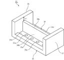
- FIG. 2 is a perspective view showing the appearance of the inkjet head cleaning device used in the first embodiment of the present invention.
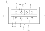
- FIG. 3 is a plan view of the inkjet head cleaning device used in the first embodiment of the present invention.
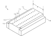
- FIG. 4 is a schematic perspective view of the inkjet head for explaining the nozzle opening surface of the inkjet head.
- FIG. 5 is a schematic front sectional view for explaining a step of removing the liquid on the nozzle opening surface of the ink jet head by the ink jet head cleaning device according to the first embodiment.
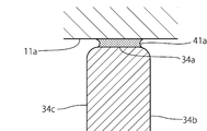
- FIG. 6 is a partially cutaway sectional view showing a part of FIG. 5 in an enlarged manner.
- FIG. 7 is a front sectional view for explaining an inkjet head cleaning apparatus according to the second embodiment.
- FIG. 8 is a perspective view showing an ink jet head used in the ink jet printing apparatus according to the second embodiment of the present invention.
- FIG. 9 is a cross-sectional view of a portion along line XX in FIG.
- FIG. 10 is a perspective view showing an inkjet head cleaning device used in the second embodiment of the present invention.
- FIG. 11 is a cross-sectional view showing the relationship between the inkjet head cleaning apparatus and inkjet according to the second embodiment of the present invention.
- FIG. 12 is a cross-sectional view for explaining a process of cleaning the ink jet head by the ink jet head cleaning device according to the third embodiment of the present invention.
- FIG. 13 is a schematic configuration diagram for explaining an inkjet head cleaning device according to a fourth embodiment of the present invention.
- FIG. 1 is a schematic configuration diagram of an ink jet printing apparatus according to a first embodiment of the present invention.
- the inkjet printing apparatus 1 is suitably used for printing an adhesive with high viscosity. That is, an adhesive is used as the ink. However, the use of the inkjet printing apparatus 1 is not limited to such adhesive printing.
- a liquid as ink is ejected from the inkjet head 11, and printing is performed.
- the inkjet head 11 has a nozzle opening surface 11a.
- a plurality of nozzle holes 11b are opened in the nozzle opening surface 11a. From this nozzle hole 11b, the liquid as ink is ejected as droplets and adheres to the substrate.
- a cleaning device 31 for the inkjet head 11 that cleans the nozzle opening surface 11a of the inkjet head 11 is provided.
- the cleaning device 31 has a cleaning head 32.
- a suction device 33 is connected to the cleaning head 32.
- FIG. 3 is a plan view of the cleaning head 32.
- the cleaning head 32 includes a wiper body 34, a base portion 35, and protective walls 36 and 37.
- the wiper body 34 has a tip surface 34a.
- the cleaning head 32 is made of an appropriate rigid material such as synthetic resin or metal.
- the material of the wiper body 34, particularly the material of the tip surface 34a is preferably a material that is ink-philic compared to the material of the nozzle surface of the inkjet head. Specifically, metals such as stainless steel and aluminum are preferable. This is because when a droplet is swept by cleaning, which will be described later, particularly when the wiper main body 34 is separated from the nozzle surface, the droplet remains on the surface of the tip surface 34a of the wiper main body 34 instead of the nozzle surface. This is desirable.
- the base part 35 has a substantially flat plate shape.
- a wiper body 34 is erected upward from the upper surface of the base portion 35. During cleaning, a liquid film is formed between the tip end surface 34 a of the wiper body 34 and the nozzle opening surface 11 a of the inkjet head 11. This will be described in detail later.
- the distal end surface 34a has a rectangular planar shape in the present embodiment.
- the tip surface 34a is a flat surface.
- the first and second side walls 34b and 34c are connected so as to extend downward from both end edges of the front end surface 34a.
- a plurality of discharge ports 35a are opened on the upper surface of the base portion 35 on the outer sides of the first and second side walls 34b and 34c.
- the plurality of discharge ports 35a are connected to the suction device 33 shown in FIG.
- the plurality of discharge ports 35a are formed to discharge the liquid that has moved downward.
- the discharge port 35a is a suction port that discharges liquid by suction.
- a suction device 33 is provided in the present embodiment.
- the suction device 33 includes an appropriate suction source such as a suction pump.
- the discharge port 35 a is provided in a recess 35 b provided on the upper surface of the base portion 35.
- the recess 35b is not necessarily required, but by providing the recess 35b, the liquid flowing down through the first and second side walls 34b, 34c can be kept in the recess 35b. That is, scattering and leakage of liquid from the upper surface of the base portion 35 to the outside can be effectively suppressed.
- Protective walls 36 and 37 are integrally provided on the upper end of the wiper body 34.
- the protective walls 36 and 37 extend from the upper surface of the base portion 35, and the height thereof is higher than the height of the wiper body 34. That is, the upper ends of the protective walls 36 and 37 are made higher than the tip surface 34a.
- the length of the tip end surface 34a that is, the length in the direction connecting the protective walls 36 and 37 is made larger than the width W (see FIG. 4) of the nozzle opening surface 11a of the inkjet head 11.
- the width of the nozzle opening surface 11a of the ink jet head 11 is substantially equal to the length of the tip surface 34a.
- head cover portions 11c and 11d are integrally provided on the nozzle opening surface 11a as schematically shown in FIG.
- the head cover portions 11c and 11d are made of a material having excellent durability such as metal.
- the dimension H2 shown in FIG. 4 is the distance between the nozzle opening surface 11a and the surface 11c1 on the nozzle opening surface 11a side of the head cover portion 11c.
- the cleaning head 32 is swept along the length direction of the inkjet head 11 as shown by the arrow in the figure.
- the front end surface 34a of the wiper body 34 is opposed to the nozzle opening surface 11a with a predetermined clearance. This clearance is adjusted so that the liquid film 41a shown in FIG. 5 can be formed.
- the size of the clearance varies depending on the viscosity and temperature of the target liquid, but is desirably about 0.02 mm to 0.3 mm, more preferably about 0.05 mm to 0.15 mm. Within this range, it is difficult to collide with the unevenness caused by the production of the nozzle surface, and it becomes possible to capture small droplets more reliably.
- the cleaning head 32 is swept while the suction device 33 performs suction from the discharge port 35a.
- the clearance is set as described above, if the droplet 41 is present on the nozzle opening surface 11a, the tip surface 34a and the nozzle opening surface of the inkjet head 11 as shown in FIG.
- a liquid film 41a is formed between the first and second electrodes 11a.
- the liquid forming the liquid film 41a flows down from the front end surface 34a toward the first and second side walls 34b, 34c, and flows down into the above-described concave portion 35b of the base portion 35. Accordingly, the liquid that has flowed down from the discharge port 35a can be sucked and removed by suction by the suction device 33.
- the tip surface 34a is a plane parallel to the nozzle opening surface 11a.
- the tip surface 34a may be a curved surface as shown in a front sectional view in FIG.
- the leading end surface 34a is curved so as to protrude toward the ink jet head.
- the tip surface 34a may be curved, and the shape thereof is not particularly limited as long as the liquid film can be formed between the nozzle opening surface.
- the nozzle opening surface 11a of the inkjet head 11 can be kept clean.
- the inkjet printing apparatus 1 of this embodiment is provided with the said cleaning apparatus 31,
- the other structure of the inkjet printing apparatus 1 is not specifically limited. Another configuration will be described with reference to FIG.
- the inkjet printing apparatus 1 has a tank 5.
- the tank 5 stores an adhesive, which is a liquid having a relatively high viscosity, as ink.
- the physical structure of the tank 5 is not particularly limited.
- the tank 5 has an outlet 5a and a recovery port 5b.
- the flow path 3 is connected to the outlet 5 a of the tank 5.
- the flow path 3 can be formed by appropriate piping.
- the liquid is ejected from an inkjet head 11 described later, and printing is performed.
- the upstream side of the inkjet head 11 in the channel 3 is referred to as an upstream channel portion 3a, and the downstream channel portion of the inkjet head 11 is referred to as a downstream channel portion 3b.
- the upstream flow path portion 3 a is connected to the upstream port of the inkjet head 11.
- a downstream flow path portion 3 b is connected to a downstream port of the inkjet head 11.
- a suction pump 26 is connected to the downstream flow path portion 3b.
- the downstream end of the downstream flow path portion 3 b is connected to the recovery port 5 b of the tank 5.
- the inkjet head 11 is configured to eject liquid as ink as droplets.
- the structure of the inkjet head 11 is not particularly limited, and an inkjet head using a piezoelectric element or an inkjet head using a thermal element can be used.
- the ink jet printing apparatus 1 of the above embodiment is not limited to the above structure.
- the suction pump 26 is composed of an appropriate pump capable of transporting liquid in the flow path 3.
- an appropriate liquid driving pump such as a diaphragm type or a roller type can be used.
- the present invention can be applied not only to the apparatus using one inkjet head 11 shown in FIG. 1 but also to an inkjet printing apparatus having a plurality of inkjet heads.
- a plurality of liquid feed pumps and suction pumps may be provided for the pump.
- FIG. 8 is a perspective view showing an ink jet head used in the ink jet printing apparatus according to the second embodiment of the present invention.
- FIG. 9 is a sectional view taken along line XX of FIG.
- the inkjet head 51 used in the present embodiment includes a head main body 52 and a case portion 53.
- the head body 52 has a nozzle opening surface 52a.
- a plurality of nozzle holes 52b are opened in the nozzle opening surface 52a.
- a case portion 53 having a portion surrounding the nozzle opening surface 52 a is attached to the head body 52.
- the inkjet head 51 is illustrated with the nozzle opening surface 52a positioned downward.
- the case portion 53 is made of a metal such as stainless steel. But the material which comprises the case part 53 is not specifically limited.
- the case portion 53 has a case surface 53a substantially parallel to the nozzle opening surface 52a. As shown in FIG. 8, the case surface 53a has a rectangular frame shape. And the nozzle opening surface 52a protrudes from the case surface 53a. Further, a notch 53b is provided on the case main body 52 side of the case surface 53a. A groove is formed by the notch 53 b and the side surface of the head main body 52.
- the nozzle opening surface 52a protrudes from the case surface 53a because, as will be described later, when the nozzle opening surface 52a is cleaned by the inkjet head cleaning device, the tip surface of the wiper body and the case surface 53a This is to provide a sufficiently large clearance between them. Thereby, it is possible to suppress the liquid such as ink from adhering to the case surface 53a.
- FIG. 10 is a perspective view showing an inkjet head cleaning device used in the second embodiment.
- the inkjet head cleaning device 61 has a wiper body 62.
- the wiper main body 62 is provided with a front end surface 62a and first and second side walls 62b and 62c connected to the front end surface 62a.
- the distal end surface 62a forms a clearance with the nozzle opening surface 52a, thereby forming a liquid film with a liquid on the nozzle opening surface 52a, as in the first embodiment.
- the clearance is large enough to form the liquid film.
- the base portion 63 is provided with a plurality of discharge ports 63a.
- the direction which connects the said 1st, 2nd side walls 62b and 62c be a width direction.
- a direction perpendicular to the width direction and the vertical direction is defined as a length direction.
- Protection walls 64 and 65 are provided on both sides in the length direction of the first and second side walls 62b and 62c.
- inkjet head placement surfaces 64a and 65a are provided on the protective walls 64 and 65, respectively.
- the inkjet head mounting surfaces 64a and 65a are provided inside the protective walls 64 and 65 at a position lower than the upper ends of the protective walls 64 and 65.
- FIG. 11 is a cross-sectional view showing a state where the ink jet head 51 shown in FIG. 8 is placed on the ink jet head cleaning device 61 in the cross section taken along line YY of FIG.
- the case surfaces 53a and 53a of the inkjet head 51 are in contact with the inkjet head mounting surfaces 64a and 65a.
- the inkjet head 51 is set on the inkjet head cleaning device 61.
- the inkjet head cleaning device 61 is moved in the same manner as in the first embodiment, that is, in the direction from the paper surface to the paper back direction in FIG.
- a liquid film is formed between the ink adhering to the nozzle opening surface 52a and the tip surface 62a, and the liquid on the nozzle opening surface 52a is removed in the same manner as in the first embodiment. . That is, the liquid moves downward and is discharged from the discharge port 63a.
- the liquid on the nozzle opening surface 52a may move to the outside in the width direction of the tip surface 62a or may adhere to the outside in the width direction.
- the length direction dimension L2 of the distal end surface 62a is shorter than the dimension L1 along the length direction of the nozzle opening surface 52a. Therefore, it is difficult for the liquid to move to the case surface 53a side in the liquid film.
- the nozzle opening surface 52a protrudes from the case surface 53a as described above, and further, a groove is formed by the notch r, so that the liquid adheres to the case surface 53a. I want to.
- the length direction dimension L2 of the tip surface 62a is preferably more than 0 mm and shorter by 3 mm or less than the dimension L1 of the nozzle opening surface 52a along the length direction. In that case, the contamination of the nozzle opening surface 52a is less likely to occur.
- the length direction dimension L2 of the tip surface 62a is more preferably 0.2 mm or more and shorter than 2.0 mm than the dimension L1 of the nozzle opening surface 52a along the length direction, and is 0.4 mm. As described above, it is more preferable that the size is shorter than 1.0 mm.
- FIG. 12 is a cross-sectional view for explaining an inkjet head cleaning device according to the third embodiment.
- a blade 72 as a liquid removing member is provided in the cleaning device 71 of the ink jet head of the third embodiment. Except that the blade 72 is provided, the inkjet head cleaning device 71 is configured in the same manner as the inkjet head cleaning device 31 of the first embodiment. Therefore, the same parts are denoted by the same reference numerals, and the description thereof is omitted.
- the blade 72 is made of a material having elasticity, and is separated from the front end surface 34a of the wiper main body 34 in the running direction indicated by the arrow.
- the blade 72 is not necessarily configured integrally with the wiper body 34. However, it is preferable that the blade 72 is provided integrally with the wiper main body 34 so that the size and the operation can be simplified.
- the inkjet head cleaning device 71 When cleaning the nozzle opening surface 11a of the inkjet head 11, the inkjet head cleaning device 71 is moved in the direction indicated by the arrow. In this case, as in the case of the first embodiment, the attached liquid such as ink can be removed by the tip surface 34a. However, fine droplets as indicated by an arrow Z in FIG. Even if such fine droplets remain, the tip of the blade 72 or the vicinity of the tip contacts the nozzle opening surface 11a and scrapes off small droplets. Therefore, even if a small droplet remains, it can be scraped off by the blade 72.
- the blade 72 can be made of a material having appropriate elasticity, such as a synthetic resin or metal, as long as the above-described action can be achieved.
- a liquid removing member 73 made of a liquid absorbing material indicated by a broken line may be provided.
- the liquid absorbing material an appropriate material capable of absorbing a liquid, such as a porous material or a fiber aggregate material, can be used.
- FIG. 13 is a schematic configuration diagram showing an inkjet head cleaning device according to a fourth embodiment of the present invention.
- the inkjet head cleaning device 81 is the same as the inkjet head cleaning device of the first embodiment except that it includes a sensor 82, a clearance adjustment device 83, and a heater 84. Therefore, the same parts are denoted by the same reference numerals, and the description thereof is omitted.
- a sensor 82 is integrally provided on the base portion 35.
- the sensor 82 is provided to detect the size of the clearance between the nozzle opening surface 11 a of the inkjet head 11 and the tip surface 34 a of the wiper body 34.
- the sensor 82 can be configured using various sensors. Preferably, a non-contact type sensor is used. Thereby, contamination of the nozzle opening surface 11a can be avoided.
- the senor 82 is a non-contact type laser displacement sensor.
- the sensor 82 can detect the distance to the nozzle opening surface 11a. That is, the displacement of the nozzle opening surface 11a can be detected.
- the sensor 82 is provided integrally with the base portion 35. Therefore, the distance between the sensor 82 and the distal end surface 34a is set to be constant in advance. Therefore, the magnitude of the clearance between the nozzle opening surface 11a and the tip surface 34a can be detected based on the displacement state of the nozzle opening surface 11a obtained by the sensor 82.
- the clearance adjusting device 83 can move the wiper body 34 close to or away from the nozzle opening surface 11a.
- various reciprocating drive devices such as a drive motor and a piston can be used.
- the heater 84 is provided so as to heat at least the front end surface 34a of the wiper body 34.
- the heater 84 may be thermally coupled to the wiper body 34, or may be a heater of a type that radiates heat toward the distal end surface 34a. Therefore, a heater such as a thermistor may be used as the heater, or an element or device that emits hot air or infrared light may be used.
- the heater 84 When the heater 84 is provided, at least the viscosity of the liquid stuck to the tip surface 34a can be reduced, and the liquid can be easily discharged. Further, not only the front end surface 34a but also the liquid adhering to the first and second side walls 34b and 34c of the wiper main body 34 and the base portion 35 can be easily reduced in viscosity by the heat retention by the heater 84. It can be discharged.
- the desired clearance range is a clearance size range in which the liquid film described above can be formed and the liquid can be easily removed. While the inkjet head cleaning device 81 is being driven, if the clearance size detected by the sensor 82 is outside the desired clearance range, the clearance adjustment device 83 is driven to determine the clearance size. What is necessary is just to adjust so that it may become in a desired clearance range.
- the size of the clearance is detected in advance by the sensor 82, and the clearance adjusting device 83 is driven when the size of the clearance is outside the above-described desired clearance range. Adjust the clearance. Thereafter, a cleaning operation by the inkjet head cleaning device 81 is executed.
- the clearance adjustment may be continued during the cleaning operation or may be performed before the cleaning operation.
- the ink jet printing apparatus of the present invention is not limited to an adhesive, and can be suitably used when a liquid with a high surface is used as ink.
- Head body 52a ... Nozzle opening surface 52b ... Nozzle hole 53 ... Case portion 53a ... Case surface 53b ... Notch 61 ... Cleaning device 62 ; Wiper body 62a... End surfaces 62b and 62c... First and second side walls 63... Base portion 63a. 4, 65 ... Protective walls 64a, 65a ... Inkjet head mounting surface 71 ... Cleaning device 72 ... Blade 73 ... Liquid removal member 81 ... Cleaning device 82 ... Sensor 83 ... Clearance adjusting device 84 ... Heater L1 ... Dimensions along the length direction L2: Length dimension
Landscapes
- Ink Jet (AREA)
Abstract
高粘度のインクなどの液体を用いた場合であっても、該液体を容易に除去することができる、インクジェットヘッドのクリーニング装置を提供する。 先端面34aと、先端面34aに連なる第1,第2の側壁34b、34cを有するワイパー本体34と、ワイパー本体34と一体に設けられたベース部35とを備え、ベース部35に排出口35aが開口しており、上記先端面34aがインクジェットヘッドのノズル開口面との間でクリアランスを形成するように構成されている、インクジェットヘッドのクリーニング装置。
Description
本発明は、様々な液体を印刷するのに用いられるインクジェット印刷装置のインクジェットヘッドのクリーニング装置及び該インクジェットヘッドのクリーニング装置を有するインクジェット印刷装置に関する。
従来、インクジェット印刷装置がよく用いられている。インクジェット印刷装置では、インクジェットヘッドが清浄に保たれていることが必要である。下記の特許文献1には、インクジェットヘッドのクリーニング装置が開示されている。下記の特許文献1では、インクジェットヘッドのノズル開口面に対向するクリーニング面を有するクリーニングヘッドが用いられている。このクリーニング面は、撥インク面と、親インク面とを有している。親インク面には吸引口が設けられている。この吸引口からインクジェットヘッドのノズル開口面に付着している液体を吸引除去する。より具体的には、親インク面を、ノズル開口面と隙間を隔てた状態とする。ノズル開口面と親インク面との間に除去すべき液体からなる液膜を形成しつつ、クリーニングヘッドを掃引し、上記吸引口から液膜を形成している液体を吸引除去する。
インクジェットヘッドのノズル開口面に付着している液滴が大きい場合、上記特許文献1に記載のクリーニングヘッドを用いた場合、親インク面とノズル開口面との間に良好な液膜を形成することが困難となる。そのため、液滴が側方に零れ落ちることがあった。また、上記ノズル開口面と親インク面との間のクリアランスよりも小さい径の液滴を拭き取ることができなかった。特に、吸引しつつ、掃引するため、上記液膜が壊れやすく、小さな液滴が残存しがちであった。また、液体の粘度が高くなると、上記のような微小な液滴がより一層残存しがちであった。
本発明の目的は、インクジェットヘッドのノズル開口面に付着しているインクなどの液体が高粘度であっても、該液体を容易に除去することができる、インクジェットヘッドのクリーニング装置を提供することにある。
本発明の他の目的は、上記インクジェットヘッドのクリーニング装置を備えたインクジェット印刷装置を提供することにある。
本発明のある広い局面によれば、インクジェットヘッドのクリーニング装置であって、インクジェットヘッドのノズル開口面との間で、インクジェットヘッドのノズル開口面との間でクリアランスを形成する先端面と、前記先端面に連なっており、かつ対向し合っている第1,第2の側壁とを有するワイパー本体と、前記ワイパー本体の下端に連ねられており、かつワイパー本体の前記第1,第2の側壁と交差する方向に延ばされたベース部とを備え、前記ベース部に、前記ワイパー本体の先端面側から下方に移動してきた液状物を排出する排出口が設けられている、インクジェットヘッドのクリーニング装置が提供される。
本発明に係るインクジェットヘッドのクリーニング装置のある特定の局面では、前記ベース部の上面が、前記第1,第2の側壁と略直交する方向に延ばされており、該ベース部の上面に前記排出口が開口している。
本発明に係るインクジェットヘッドのクリーニング装置の他の特定の局面では、前記排出口が複数設けられている。この場合には、液体をより一層確実に排出することができる。
本発明に係るインクジェットヘッドのクリーニング装置の別の特定の局面では、前記第1の側壁及び第2の側壁の各外側において、前記ベース部の上面に複数の前記排出口が設けられている。この場合には、ベース部側に垂れてきた液体を複数の排出口から容易にかつ確実に除去することができる。
本発明に係るインクジェットヘッドのクリーニング装置の他の特定の局面では、前記ベース部の上面に凹部が設けられており、前記排出口が前記凹部内に配置されている。
本発明に係るインクジェットヘッドのクリーニング装置の他の特定の局面では、前記排出口に接続された吸引装置がさらに備えられている。
本発明に係るインクジェットヘッドのクリーニング装置の別の特定の局面では、前記ノズル開口面の外側にケース部分を有するインクジェットヘッドのクリーニング装置であって、前記第1,第2の側壁を結ぶ方向を幅方向、前記幅方向及び上下方向と直交する方向を長さ方向とした場合、前記ワイパー本体の前記先端面の長さ方向寸法が、クリーニングされるインクジェットヘッドのノズル開口面の長さ方向寸法よりも短い。この場合には、ノズル開口面の外側のケース部分へのインクなどの液体の付着を抑制することができる。
本発明に係るインクジェットヘッドのクリーニング装置のさらに他の特定の局面では、前記ワイパー本体の前記先端面よりも、前記ワイパー本体の走行方向後方に隔てられて配置されており、前記インクジェットヘッドの前記ケース部に付着している液体を除去するための液体除去部材がさらに備えられている。この場合には、ケース部に付着している液体を液体除去部材により除去することができる。
上記液体除去部材は、弾力性を有するブレードであってもよく、液体吸収材料からなるものであってもよい。
本発明に係るインクジェットヘッドのクリーニング装置の他の特定の局面では、前記ワイパー本体の前記先端面と、前記インクジェットヘッドのノズル開口面との間のクリアランスの大きさを検出するセンサーと、前記クリアランスの大きさを調整するように前記ワイパー本体の位置を変化させるクリアランス調整装置とがさらに備えられている。
本発明に係るインクジェットヘッドのクリーニング装置のさらに他の特定の局面では、前記センサーが、非接触式センサーである。
本発明に係るインクジェットヘッドのクリーニング装置の別の特定の局面では、前記ワイパー本体の少なくとも前記先端面を加熱するように設けられたヒーターがさらに備えられている。
本発明に係るインクジェットヘッドのクリーニング装置の別の特定の局面では、前記先端面が、平坦面である。
本発明に係るインクジェットヘッドのクリーニング装置の別の特定の局面では、前記先端面が、前記第1及び第2の側壁と直交する方向の断面において、インクジェットヘッド側に突出しているように湾曲している曲面状である。
本発明に係るインクジェット印刷装置は、インクとしての液体を供給する液体供給源と、前記液体供給源に接続されている流路と、前記流路に接続されており、前記液体を搬送するためのポンプと、前記流路に接続されており、インクとしての前記液体を吐出するノズル開口面が設けられている、インクジェットヘッドと、前記インクジェットヘッドのノズル開口面上の液体を除去するためのインクジェットヘッドのクリーニング装置であって、本発明に従って構成されたインクジェットヘッドのクリーニング装置とを備える。
本発明に係るインクジェットヘッドのクリーニング装置及びインクジェット印刷装置によれば、インクジェットヘッドのノズル開口面に付着しているインクなどの液体が高粘度の場合であっても、容易に除去することができる。
以下、図面を参照しつつ、本発明の具体的な実施形態を説明することにより、本発明を明らかにする。
図1は、本発明の第1の実施形態に係るインクジェット印刷装置の概略構成図である。
インクジェット印刷装置1は、粘度の高い接着剤の印刷に好適に用いられる。すなわち、インクとして、接着剤が用いられる。もっとも、インクジェット印刷装置1の用途は、このような接着剤の印刷に限定されるものではない。
インクジェット印刷装置1では、インクジェットヘッド11からインクとしての液体を吐出し、印刷する。
図4に模式的斜視図で示すように、インクジェットヘッド11は、ノズル開口面11aを有する。ノズル開口面11aに、複数のノズル穴11bが開口している。このノズル穴11bから、インクとしての液体が液滴として吐出され、被印刷物上に付着される。
ところで、インクジェットヘッド11を用いた印刷に際しては、ノズル開口面11aが清浄に保たれる必要がある。例えば、余分なインクのような液体が、ノズル開口面11a上、特にノズル穴11b近傍に付着していると、印刷精度が劣化したり、印刷の品位が劣化したりするおそれがある。
本実施形態のインクジェット印刷装置1では、上記インクジェットヘッド11のノズル開口面11aをクリーニングするインクジェットヘッド11のクリーニング装置31が備えられている。
クリーニング装置31は、クリーニングヘッド32を有する。クリーニングヘッド32に、吸引装置33が接続されている。
クリーニングヘッド32の外観を図2に斜視図で示す。また、図3は、クリーニングヘッド32の平面図である。
クリーニングヘッド32は、ワイパー本体34と、ベース部35と、保護壁36,37とを有する。ワイパー本体34は、先端面34aを有する。
クリーニングヘッド32は、合成樹脂や金属などの適宜の剛性材料からなる。ワイパー本体34の材質、特に先端面34aの材質は、インクジェットヘッドのノズル面の材質に比べ親インク性である材質が好ましい。具体的には、ステンレスやアルミ等の金属が好ましい。これは、後述するクリーニングにより液滴を掃引する際、特に、ノズル面よりワイパー本体34が離れるワイプ終了時に、液滴がノズル面でなく、ワイパー本体34の先端面34aの表面に残存させることが望ましいためである。
ベース部35は、略平板状の形状を有している。ベース部35の上面から上方にワイパー本体34が立設されている。クリーニングに際し、ワイパー本体34の先端面34aは、インクジェットヘッド11のノズル開口面11aとの間に、液膜を形成する。この点については、後程、詳細に説明する。
先端面34aは、本実施形態では矩形の平面形状を有している。また、先端面34aは、平坦面とされている。
先端面34aの両端縁から下方に延びるように、第1,第2の側壁34b、34cが連ねられている。
また、第1及び第2の側壁34b、34cの各外側において、ベース部35の上面に複数の排出口35aが開口している。この複数の排出口35aは、図1に示した吸引装置33に接続されている。
複数の排出口35aは、下方に移動してきた液体を排出するために形成されている。好ましくは、排出口35aは吸引により液体を排出する吸引口である。吸引口として用いるために、本実施形態では、吸引装置33が設けられている。上記吸引装置33は、吸引ポンプなどの適宜の吸引源からなる。
図2に示すように、排出口35aは、ベース部35の上面に設けられた凹部35b内に設けられている。凹部35bは必ずしも必要ではないが、凹部35bを設けることにより、第1,第2の側壁34b、34cをつたって流下してきた液体を凹部35b内にとどめることができる。すなわち、ベース部35の上面から外側への液体の飛散や漏れを効果的に抑制することができる。
上記ワイパー本体34の上端に、保護壁36,37が一体的に設けられている。保護壁36,37は、ベース部35の上面から延び、その高さは、ワイパー本体34の高さよりも高くされている。すなわち、先端面34aに比べて、保護壁36,37の上端の方が高くされている。
上記先端面34aの長さ、すなわち保護壁36,37を結ぶ方向の長さは、インクジェットヘッド11のノズル開口面11aの幅W(図4参照)よりも大きくされている。好ましくは、インクジェットヘッド11のノズル開口面11aの幅と、上記先端面34aの長さとがほぼ同等とされる。それによって、保護壁36,37をガイド壁として利用して、後述の掃引を安定に行うことができる。また、インクジェットヘッド11では、ノズル開口面11aにおいて、図4に略図的に示すように、ヘッドカバー部11c,11dが一体に設けられている。ヘッドカバー部11c,11dは、金属などの耐久性に優れた材料からなる。図2に示す寸法H1は、保護壁36の先端と、上記先端面34aとの間の距離である。これに対して、図4に示す寸法H2は、上記ヘッドカバー部11cのノズル開口面11a側の面11c1とノズル開口面11aとの間の距離である。本実施形態では、寸法H1>H2とされている。従って、上記保護壁36,37の先端が、インクジェットヘッド11の上記ヘッドカバー部11c,11dに当接することによりガイドとして機能を果たしつつ、先端面34aがノズル面に一定の距離を保ちつつワイパー本体34を掃引することが出来る。上記のように、ヘッドカバー部11c,11dは、丈夫な部材で出来ていることが多いため、傷をつけるなどの問題の発生が少なく、ノズル開口面11aへの影響も少ない。
インクジェットヘッド11のクリーニング装置31を用いたクリーニング操作を、図5を参照して説明する。
図5に略図的正面断面図で示すように、インクジェットヘッド11のノズル開口面11a上に複数の液滴41が存在しているとする。この液滴41を除去するために、上記クリーニングヘッド32を図示の矢印で示すように、インクジェットヘッド11の長さ方向に沿って掃引する。掃引に先立ち、ワイパー本体34の先端面34aをノズル開口面11aと所定のクリアランスを隔てるように対向させる。このクリアランスは、図5において示されている液膜41aを形成し得るように調整する。このクリアランスの大きさは、対象とする液体の粘度や温度によっても異なるが、0.02mm~0.3mm、更に好ましくは0.05mm~0.15mm程度とすることが望ましい。この範囲内であると、ノズル面の製造上によって生じる凹凸に衝突し難く、小さな液滴をより確実に捕捉することが可能となる。
上記のように先端面34aを位置決めした状態で、吸引装置33により排出口35aからの吸引を行いつつ、クリーニングヘッド32を掃引する。この時、上記のようにクリアランスが設定されているため、ノズル開口面11a上に液滴41が存在していると、図6に示すように、先端面34aと、インクジェットヘッド11のノズル開口面11aとの間に液膜41aが形成される。そして、上記掃引を続けると、液膜41aを形成している液体が先端面34aから第1,第2の側壁34b、34c側に流下し、ベース部35の前述した凹部35b内に流れ落ちる。従って、吸引装置33による吸引により、排出口35aから、流れ落ちてきた液体を吸引し、除去することができる。
なお、第1の実施形態では、上記先端面34aはノズル開口面11aと平行な平面であったが、図7に正面断面図で示すように、先端面34aは、曲面であってもよい。ここでは、インクジェットヘッド側に突出するように、先端面34aが曲面状とされている。
このように、先端面34aは、曲面状であってもよく、液膜をノズル開口面との間で形成し得る限り、その形状は特に限定されるものではない。
上記インクジェットヘッド11のクリーニング装置31を用いることにより、インクジェットヘッド11のノズル開口面11aを清浄に保つことができる。
従って、インクジェット印刷装置1における印刷精度の低下や印刷品位の劣化を効果的に抑制することができる。
なお、本実施形態のインクジェット印刷装置1は、上記クリーニング装置31が備えられていることを特徴とし、インクジェット印刷装置1の他の構成は特に限定されない。図1を参照して、他の構成を説明することとする。
インクジェット印刷装置1は、タンク5を有する。タンク5に、インクとしての、上記比較的粘度の高い液体である接着剤が貯留されている。なお、タンク5の物理的な構造は特に限定されない。
タンク5は、出口5a及び回収口5bを有する。
タンク5の出口5aに、流路3の一端が接続されている。流路3は、適宜の配管により形成され得る。
インクジェット印刷装置1では後述のインクジェットヘッド11から、上記液体を吐出し、印刷する。流路3のインクジェットヘッド11の上流側を上流側流路部分3aとし、インクジェットヘッド11の下流側の流路部分を下流側流路部分3bとする。上流側流路部分3aがインクジェットヘッド11の上流側のポートに接続されている。インクジェットヘッド11の下流側のポートに下流側流路部分3bが接続されている。下流側流路部分3bには、吸引ポンプ26が接続されている。下流側流路部分3bの下流側端部は、タンク5の回収口5bに接続されている。
インクジェットヘッド11は、インクとしての液体を、液滴として吐出するように構成されている。このインクジェットヘッド11の構造は特に限定されず、圧電素子を用いたインクジェットヘッドや、感熱素子を用いたインクジェットヘッドを用いることができる。
上記実施形態のインクジェット印刷装置1は、上記構造に限定されるものではない。
吸引ポンプ26は、流路3において液体を搬送し得る適宜のポンプからなる。このようなポンプとしては、ダイアフラム型、ローラー型などの適宜の液体駆動用ポンプを用いることができる。
その他の構成は特に限定されず、例えば、図1に示した1つのインクジェットヘッド11を用いた装置に限らず、複数のインクジェットヘッドを有するインクジェット印刷装置にも本発明を適応することができる。
また、ポンプについても、送液ポンプや吸引ポンプを複数設けてもよい。
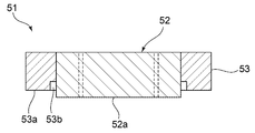
図8は、本発明の第2の実施形態に係るインクジェット印刷装置で用いられるインクジェットヘッドを示す斜視図である。図9は、図8のX-X線に沿う断面図である。
本実施形態で用いられるインクジェットヘッド51は、ヘッド本体52と、ケース部53とを有する。ヘッド本体52は、ノズル開口面52aを有する。ノズル開口面52aに、複数のノズル穴52bが開口している。そして、上記ノズル開口面52aを囲む部分を有するケース部53がヘッド本体52に取り付けられている。
図9においては、ノズル開口面52aが下方に位置する向きで、インクジェットヘッド51が図示されている。
上記ケース部53は、例えばステンレスなどの金属からなる。もっとも、ケース部53を構成する材料は特に限定されるものではない。
ケース部53は、ノズル開口面52aと略平行なケース面53aを有する。ケース面53aは、図8に示すように、矩形枠状の形状を有している。そして、ケース面53aより、ノズル開口面52aが突出している。また、ケース面53aのヘッド本体52側においては、切欠き53bが設けられている。この切欠き53bと、ヘッド本体52の側面とにより溝が形成されている。
上記ノズル開口面52aが、ケース面53aよりも突出しているのは、後述するように、ノズル開口面52aをインクジェットヘッドのクリーニング装置でクリーニングする際に、ワイパー本体の先端面とケース面53aとの間に十分大きなクリアランスを設けるためである。それによって、インク等の液体が、ケース面53aに付着するのを抑制することができる。
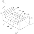
図10は、第2の実施形態で用いられるインクジェットヘッドのクリーニング装置を示す斜視図である。インクジェットヘッドのクリーニング装置61は、ワイパー本体62を有する。ワイパー本体62には、第1の実施形態の場合と同様に、先端面62aと、先端面62aに連なる第1,第2の側壁62b,62cが設けられている。先端面62aは、ノズル開口面52aとの間でクリアランスを形成し、それによって、第1の実施形態の場合と同様に、ノズル開口面52a上に液体による液膜を形成することができる。
上記クリアランスは、上記液膜を形成するのに十分な大きさとされている。
本実施形態においても、ベース部63に複数の排出口63aが設けられている。いま、上記第1,第2の側壁62b,62cを結ぶ方向を幅方向とする。この幅方向と上下方向と直交する方向を長さ方向とする。第1,第2の側壁62b,62cの上記長さ方向両側に保護壁64,65が設けられている。本実施形態では、保護壁64,65にインクジェットヘッド載置面64a,65aが設けられている。インクジェットヘッド載置面64a,65aは、保護壁64,65の上端よりも低い位置において、保護壁64,65の内側に設けられている。
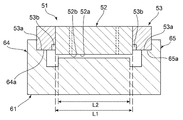
図11は、図10のY-Y線に沿う断面において、上記インクジェットヘッドのクリーニング装置61に、図8に示したインクジェットヘッド51を載置した状態を示す断面図である。
図11に示すように、インクジェットヘッド載置面64a,65a上に、インクジェットヘッド51のケース面53a,53aが当接している。このようにして、インクジェットヘッド51が、インクジェットヘッドのクリーニング装置61上にセットされる。この状態で、第1の実施形態の場合と同様にして、すなわち図11の紙面-紙背方向にインクジェットヘッドのクリーニング装置61を移動させる。ノズル開口面52a上に付着していたインクと、上記先端面62aとの間で液膜が形成され、第1の実施形態の場合と同様にして、ノズル開口面52a上の液体が除去される。すなわち、液体が下方に移動し、排出口63aから排出される。
ところで、ノズル開口面52a上の液体が、上記先端面62aの幅方向外側に移動したり、幅方向外側に付着する場合もある。しかしながら、本実施形態では、先端面62aの長さ方向寸法L2が、ノズル開口面52aの上記長さ方向に沿う寸法L1よりも短くされている。従って、上記液膜には、液体が、ケース面53a側に移動しがたい。加えて、上記ノズル開口面52aは、ケース面53aよりも前述したように突出していることによっても、さらに切欠きrにより溝が形成されていることによっても、ケース面53aに液体が付着しがたくなっている。
よって、第2の実施形態では、上記ケース部53が設けられているものの、ノズル開口面52aの周囲の液体による汚染を抑制することができる。
なお、上記先端面62aの長さ方向寸法L2は、好ましくは、ノズル開口面52aの上記長さ方向に沿う寸法のL1よりも0mmを超え、3mm以内の大きさだけ短いことが望ましい。その場合には、ノズル開口面52aの汚染がより一層生じがたい。上記先端面62aの長さ方向寸法L2は、ノズル開口面52aの上記長さ方向に沿う寸法のL1よりも0.2mm以上、2.0mm以内の大きさだけ短いことがより好ましく、0.4mm以上、1.0mm以内の大きさだけ短いことが更に好ましい。
図12は、第3の実施形態に係るインクジェットヘッドのクリーニング装置を説明するための断面図である。
図12では、第3の実施形態のインクジェットヘッドのクリーニング装置71に液体除去部材としてのブレード72が設けられている。ブレード72が設けられていることを除いては、インクジェットヘッドのクリーニング装置71は、第1の実施形態のインクジェットヘッドのクリーニング装置31と同様に構成されている。従って、同一部分については、同一の参照番号を付することによりその説明を省略する。ブレード72は、弾力性を有する材料からなり、ワイパー本体34の先端面34aよりも、矢印で示す走行方向において後方に隔てられている。ブレード72は、ワイパー本体34と一体に構成される必要は必ずしもない。もっとも、ブレード72を、ワイパー本体34に一体的に設けることにより、小型化及び操作の簡略化を図ることができ、好ましい。
インクジェットヘッド11のノズル開口面11aをクリーニングするにあたっては、矢印で示す方向に、インクジェットヘッドのクリーニング装置71を移動させる。この場合、第1の実施形態の場合と同様に、先端面34aにより、付着していたインクなどの液体を除去することができる。もっとも、図12に矢印Zで示すような細かな液滴が残存することがある。このような細かな液滴残存したとしても、ブレード72の先端または先端近傍部分が、ノズル開口面11aに接触し、小さな液滴をかき取る。そのため、小さな液滴が残存していたとしても、ブレード72によりかき取ることができる。
上記ブレード72は、上記作用を果たし得る限り、合成樹脂や金属などの適宜の弾力性を有する材料により構成することができる。
また、ブレード72に代えて、破線で示す液体吸収材料からなる液体除去部材73を設けてもよい。液体吸収材料としては、多孔質材料や、繊維凝集材料など液体を吸収し得る適宜の材料を用いることができる。
図13は、本発明の第4の実施形態に係るインクジェットヘッドのクリーニング装置を示す概略構成図である。
インクジェットヘッドのクリーニング装置81は、センサー82、クリアランス調整装置83及びヒーター84を備えることを除いては、第1の実施形態のインクジェットヘッドのクリーニング装置と同様である。従って、同一部分については、同一番号を付することにより、その説明を省略する。
ベース部35に、センサー82が一体的に設けられている。センサー82は、インクジェットヘッド11のノズル開口面11aと、ワイパー本体34の先端面34aとの間のクリアランスの大きさを検出するために設けられている。このクリアランスの大きさを検出し得る限り、センサー82は、様々なセンサーを用いて構成することができる。好ましくは、非接触式のセンサーが用いられる。それによって、ノズル開口面11aの汚染を避けることができる。
本実施形態では、センサー82は、非接触式のレーザー変位センサーである。この場合、センサー82は、ノズル開口面11aまでの距離を検出することができる。すなわち、ノズル開口面11aの変位を検出することができる。他方、センサー82は、ベース部35と一体に設けられている。従って、センサー82と、先端面34aとの距離は予め一定とされている。従って、上記センサー82により求められたノズル開口面11aの変位状態により、ノズル開口面11aと、先端面34aとの間のクリアランスの大きさを検出することができる。
他方、クリアランス調整装置83は、ワイパー本体34を、ノズル開口面11aに対して、近接または離間させ得る。このようなクリアランス調整装置83としては、駆動モータやピストンなど様々な往復駆動装置を用いることができる。
また、ヒーター84は、上記ワイパー本体34の少なくとも先端面34aを加熱するように設けられている。このヒーター84は、ワイパー本体34に熱結合されていてもよく、あるいは熱を先端面34a側に向かって放射する形式のヒーターであってもよい。従って、ヒーターとしては、サーミスタなどの発熱素子を用いてもよく、あるいは熱風や赤外線を放射する素子や装置を用いてもよい。
上記ヒーター84が備えられている場合、少なくとも先端面34aにこびり付いていた液体の粘度を低めることができ、該液体を容易に排出させることができる。また、先端面34aだけでなく、ワイパー本体34の第1,第2の側壁34b,34cやベース部35に付着していた液体についても、上記ヒーター84による保温により、粘度を低下させ、容易に排出させることができる。
上記インクジェットヘッドのクリーニング装置81を駆動するにあたっては、予めノズル開口面11aと先端面34aとの間の所望とするクリアランス範囲を設定しておくことが望ましい。この所望のクリアランス範囲とは、前述した液膜を形成し、液体を容易に除去し得るクリアランスの大きさの範囲である。インクジェットヘッドのクリーニング装置81を駆動する間、上記センサー82により検出されたクリアランスの大きさが、上記所望のクリアランスの範囲外である場合に、上記クリアランス調整装置83を駆動し、クリアランスの大きさが所望のクリアランス範囲内になるように調整すればよい。
あるいは、他の方法として、駆動に先立ち、予め、センサー82により、クリアランスの大きさを検出し、該クリアランスの大きさが前述した所望のクリアランス範囲外である場合に、クリアランス調整装置83を駆動し、クリアランスを調整する。しかる後、インクジェットヘッドのクリーニング装置81によるクリーニング操作を実行する。
上記のように、クリアランスの調整は、クリーニング操作の間継続されてもよく、あるいはクリーニング操作の前に行われてもよい。
本発明のインクジェット印刷装置は、接着剤に限らず、他の面の高い液体をインクとして用いる場合にも好適に用いることができる。
1…インクジェット印刷装置
3…流路
3a…上流側流路部分
3b…下流側流路部分
5…タンク
5a…出口
5b…回収口
11…インクジェットヘッド
11a…ノズル開口面
11b…ノズル穴
11c,11d…ヘッドカバー部
11c1…面
26…吸引ポンプ
31…クリーニング装置
32…クリーニングヘッド
33…吸引装置
34…ワイパー本体
34a…先端面
34b,34c…第1,第2の側壁
35…ベース部
35a…排出口
35b…凹部
36,37…保護壁
41…液滴
41a…液膜
51…インクジェットヘッド
52…ヘッド本体
52a…ノズル開口面
52b…ノズル穴
53…ケース部
53a…ケース面
53b…切欠き
61…クリーニング装置
62…ワイパー本体
62a…先端面
62b,62c…第1,第2の側壁
63…ベース部
63a…排出口
64,65…保護壁
64a,65a…インクジェットヘッド載置面
71…クリーニング装置
72…ブレード
73…液体除去部材
81…クリーニング装置
82…センサー
83…クリアランス調整装置
84…ヒーター
L1…長さ方向に沿う寸法
L2…長さ方向寸法
3…流路
3a…上流側流路部分
3b…下流側流路部分
5…タンク
5a…出口
5b…回収口
11…インクジェットヘッド
11a…ノズル開口面
11b…ノズル穴
11c,11d…ヘッドカバー部
11c1…面
26…吸引ポンプ
31…クリーニング装置
32…クリーニングヘッド
33…吸引装置
34…ワイパー本体
34a…先端面
34b,34c…第1,第2の側壁
35…ベース部
35a…排出口
35b…凹部
36,37…保護壁
41…液滴
41a…液膜
51…インクジェットヘッド
52…ヘッド本体
52a…ノズル開口面
52b…ノズル穴
53…ケース部
53a…ケース面
53b…切欠き
61…クリーニング装置
62…ワイパー本体
62a…先端面
62b,62c…第1,第2の側壁
63…ベース部
63a…排出口
64,65…保護壁
64a,65a…インクジェットヘッド載置面
71…クリーニング装置
72…ブレード
73…液体除去部材
81…クリーニング装置
82…センサー
83…クリアランス調整装置
84…ヒーター
L1…長さ方向に沿う寸法
L2…長さ方向寸法
Claims (16)
- インクジェットヘッドのクリーニング装置であって、
インクジェットヘッドのノズル開口面との間で、インクジェットヘッドのノズル開口面との間でクリアランスを形成する先端面と、前記先端面に連なっており、かつ対向し合っている第1,第2の側壁とを有するワイパー本体と、
前記ワイパー本体の下端に連ねられており、かつワイパー本体の前記第1,第2の側壁と交差する方向に延ばされたベース部とを備え、
前記ベース部に、前記ワイパー本体の先端面側から下方に移動してきた液状物を排出する排出口が設けられている、インクジェットヘッドのクリーニング装置。 - 前記ベース部の上面が、前記第1,第2の側壁と略直交する方向に延ばされており、該ベース部の上面に前記排出口が開口している、請求項1に記載のインクジェットヘッドのクリーニング装置。
- 前記排出口が複数設けられている、請求項1または2に記載のインクジェットヘッドのクリーニング装置。
- 前記第1の側壁及び第2の側壁の各外側において、前記ベース部の上面に複数の前記排出口が設けられている、請求項3に記載のインクジェットヘッドのクリーニング装置。
- 前記ベース部の上面に凹部が設けられており、前記排出口が前記凹部内に配置されている、請求項2~4のいずれか1項に記載のインクジェットヘッドのクリーニング装置。
- 前記排出口に接続された吸引装置をさらに備える、請求項1~5のいずれか1項に記載のインクジェットヘッドのクリーニング装置。
- 前記ノズル開口面の外側にケース部分を有するインクジェットヘッドのクリーニング装置であって、
前記第1,第2の側壁を結ぶ方向を幅方向、前記幅方向及び上下方向と直交する方向を長さ方向とした場合、前記ワイパー本体の前記先端面の長さ方向寸法が、クリーニングされるインクジェットヘッドのノズル開口面の長さ方向寸法よりも短い、請求項1~6のいずれか1項に記載のインクジェットヘッドのクリーニング装置。 - 前記ワイパー本体の前記先端面よりも、前記ワイパー本体の走行方向後方に隔てられて配置されており、前記インクジェットヘッドの前記ケース部に付着している液体を除去するための液体除去部材をさらに備える、請求項7に記載のインクジェットヘッドのクリーニング装置。
- 前記液体除去部材が、弾力性を有するブレードである、請求項8に記載のインクジェットヘッドのクリーニング装置。
- 前記液体除去部材が、液体吸収材料からなる、請求項8に記載のインクジェットヘッドのクリーニング装置。
- 前記ワイパー本体の前記先端面と、前記インクジェットヘッドのノズル開口面との間のクリアランスの大きさを検出するセンサーと、
前記クリアランスの大きさを調整するように前記ワイパー本体の位置を変化させるクリアランス調整装置とをさらに備える、請求項1~10のいずれか1項に記載のインクジェットヘッドのクリーニング装置。 - 前記センサーが、非接触式センサーである、請求項11に記載のインクジェットヘッドのクリーニング装置。
- 前記ワイパー本体の少なくとも前記先端面を加熱するように設けられたヒーターをさらに備える、請求項1~12のいずれか1項に記載のインクジェットヘッドのクリーニング装置。
- 前記先端面が、平坦面である、請求項1~13のいずれか1項に記載のインクジェットヘッドのクリーニング装置。
- 前記先端面が、前記第1及び第2の側壁と直交する方向の断面において、インクジェットヘッド側に突出しているように湾曲している曲面状である、請求項1~14のいずれか1項に記載のインクジェットヘッドのクリーニング装置。
- インクとしての液体を供給する液体供給源と、
前記液体供給源に接続されている流路と、前記流路に接続されており、前記液体を搬送するためのポンプと、
前記流路に接続されており、インクとしての前記液体を吐出するノズル開口面が設けられている、インクジェットヘッドと、
前記インクジェットヘッドのノズル開口面上の液体を除去するためのインクジェットヘッドのクリーニング装置であって、請求項1~15のいずれか1項に記載のインクジェットヘッドのクリーニング装置とを備える、インクジェット印刷装置。
Priority Applications (1)
| Application Number | Priority Date | Filing Date | Title |
|---|---|---|---|
| JP2016544880A JPWO2017002857A1 (ja) | 2015-07-01 | 2016-06-29 | インクジェットヘッドのクリーニング装置及びインクジェット印刷装置 |
Applications Claiming Priority (2)
| Application Number | Priority Date | Filing Date | Title |
|---|---|---|---|
| JP2015-132485 | 2015-07-01 | ||
| JP2015132485 | 2015-07-01 |
Publications (1)
| Publication Number | Publication Date |
|---|---|
| WO2017002857A1 true WO2017002857A1 (ja) | 2017-01-05 |
Family
ID=57609616
Family Applications (1)
| Application Number | Title | Priority Date | Filing Date |
|---|---|---|---|
| PCT/JP2016/069273 Ceased WO2017002857A1 (ja) | 2015-07-01 | 2016-06-29 | インクジェットヘッドのクリーニング装置及びインクジェット印刷装置 |
Country Status (3)
| Country | Link |
|---|---|
| JP (1) | JPWO2017002857A1 (ja) |
| TW (1) | TW201707989A (ja) |
| WO (1) | WO2017002857A1 (ja) |
Citations (4)
| Publication number | Priority date | Publication date | Assignee | Title |
|---|---|---|---|---|
| JP2005119024A (ja) * | 2003-10-14 | 2005-05-12 | Olympus Corp | 画像記録装置 |
| JP2006212870A (ja) * | 2005-02-02 | 2006-08-17 | Canon Inc | インクジェット記録装置 |
| JP2011110782A (ja) * | 2009-11-26 | 2011-06-09 | Kyocera Mita Corp | インクジェット記録装置 |
| JP2011212885A (ja) * | 2010-03-31 | 2011-10-27 | Seiren Co Ltd | インクジェット記録装置および記録ヘッドのメンテナンス方法 |
Family Cites Families (11)
| Publication number | Priority date | Publication date | Assignee | Title |
|---|---|---|---|---|
| JP2676165B2 (ja) * | 1989-11-16 | 1997-11-12 | キヤノン株式会社 | インクジェット記録装置 |
| JPH07323554A (ja) * | 1994-06-01 | 1995-12-12 | Sharp Corp | インクジェット記録装置 |
| JP2005081594A (ja) * | 2003-09-05 | 2005-03-31 | Seiko Epson Corp | 液体噴射装置 |
| JP2005262822A (ja) * | 2004-03-22 | 2005-09-29 | Seiko Epson Corp | キャッピング装置及び液滴吐出装置 |
| JP2006062263A (ja) * | 2004-08-27 | 2006-03-09 | Sharp Corp | インクジェット記録装置 |
| JP4258732B2 (ja) * | 2004-09-10 | 2009-04-30 | 富士フイルム株式会社 | 画像形成装置 |
| JP2007137026A (ja) * | 2005-11-22 | 2007-06-07 | Fujifilm Corp | 液体吐出装置および液体攪拌方法 |
| JP2012171294A (ja) * | 2011-02-23 | 2012-09-10 | Seiko Epson Corp | 液体噴射装置 |
| JP6056275B2 (ja) * | 2012-08-30 | 2017-01-11 | セイコーエプソン株式会社 | 液体噴射ヘッドのメンテナンス方法及び液体噴射装置 |
| JP6003636B2 (ja) * | 2012-12-28 | 2016-10-05 | ブラザー工業株式会社 | 液体吐出装置および液体吐出装置の制御プログラム |
| JP5871860B2 (ja) * | 2013-06-28 | 2016-03-01 | 京セラドキュメントソリューションズ株式会社 | 記録ヘッドの回復機構及びそれを備えたインクジェット記録装置、並びに記録ヘッドの回復方法 |
-
2016
- 2016-06-29 WO PCT/JP2016/069273 patent/WO2017002857A1/ja not_active Ceased
- 2016-06-29 JP JP2016544880A patent/JPWO2017002857A1/ja active Pending
- 2016-07-01 TW TW105121029A patent/TW201707989A/zh unknown
Patent Citations (4)
| Publication number | Priority date | Publication date | Assignee | Title |
|---|---|---|---|---|
| JP2005119024A (ja) * | 2003-10-14 | 2005-05-12 | Olympus Corp | 画像記録装置 |
| JP2006212870A (ja) * | 2005-02-02 | 2006-08-17 | Canon Inc | インクジェット記録装置 |
| JP2011110782A (ja) * | 2009-11-26 | 2011-06-09 | Kyocera Mita Corp | インクジェット記録装置 |
| JP2011212885A (ja) * | 2010-03-31 | 2011-10-27 | Seiren Co Ltd | インクジェット記録装置および記録ヘッドのメンテナンス方法 |
Also Published As
| Publication number | Publication date |
|---|---|
| JPWO2017002857A1 (ja) | 2018-04-19 |
| TW201707989A (zh) | 2017-03-01 |
Similar Documents
| Publication | Publication Date | Title |
|---|---|---|
| US9610767B2 (en) | Liquid ejecting apparatus | |
| KR102635289B1 (ko) | 잉크젯 헤드의 클리닝 장치, 클리닝 방법, 및, 인자 장치 | |
| JP3835532B2 (ja) | インクジェット式印刷装置 | |
| CN101669048B (zh) | 液体材料喷出装置的清洁装置和该清洁装置中进行的辊子旋转控制方法 | |
| US8465121B2 (en) | Fluid ejecting apparatus and wiping method | |
| JP6256078B2 (ja) | 液体吐出装置、および吐出異常検査方法 | |
| CN202528588U (zh) | 液体喷射装置 | |
| JP7014933B2 (ja) | 印刷機械 | |
| CN101663167B (zh) | 液体材料喷出装置的清洁装置 | |
| CN105313455B (zh) | 液体喷出设备 | |
| JP4484939B2 (ja) | 液滴吐出装置 | |
| JP2017074759A (ja) | 液体噴射ヘッド、及び液体噴射装置 | |
| JP5261356B2 (ja) | インクジェット記録装置 | |
| JP2009112954A (ja) | 塗布方法 | |
| US7490921B2 (en) | Maintenance apparatus of recording head | |
| JP4257367B2 (ja) | 液体材料吐出装置のクリーニング装置 | |
| JPWO2017002857A1 (ja) | インクジェットヘッドのクリーニング装置及びインクジェット印刷装置 | |
| JP5740431B2 (ja) | インクジェット記録装置 | |
| JP2013052507A (ja) | 洗浄装置、液体吐出装置及びインクジェットヘッドの洗浄方法 | |
| US9421777B2 (en) | Liquid ejecting apparatus | |
| JP6519121B2 (ja) | 画像形成装置、吐出検知ユニット、液体吐出装置 | |
| US8376507B2 (en) | Non-contact inkjet print head cleaning | |
| CN106476437B (zh) | 液体喷出头以及液体喷出装置 | |
| JP6473387B2 (ja) | 液体噴射ヘッド及び液体噴射装置 | |
| JP6634600B2 (ja) | 塗布ヘッドのクリーニング装置とクリーニング方法 |
Legal Events
| Date | Code | Title | Description |
|---|---|---|---|
| ENP | Entry into the national phase |
Ref document number: 2016544880 Country of ref document: JP Kind code of ref document: A |
|
| 121 | Ep: the epo has been informed by wipo that ep was designated in this application |
Ref document number: 16817965 Country of ref document: EP Kind code of ref document: A1 |
|
| NENP | Non-entry into the national phase |
Ref country code: DE |
|
| 122 | Ep: pct application non-entry in european phase |
Ref document number: 16817965 Country of ref document: EP Kind code of ref document: A1 |