WO2017002187A1 - Machine de travail sur substrats et procédé de reconnaissance - Google Patents
Machine de travail sur substrats et procédé de reconnaissance Download PDFInfo
- Publication number
- WO2017002187A1 WO2017002187A1 PCT/JP2015/068763 JP2015068763W WO2017002187A1 WO 2017002187 A1 WO2017002187 A1 WO 2017002187A1 JP 2015068763 W JP2015068763 W JP 2015068763W WO 2017002187 A1 WO2017002187 A1 WO 2017002187A1
- Authority
- WO
- WIPO (PCT)
- Prior art keywords
- movable
- main body
- insertion hole
- lead
- cutting tool
- Prior art date
Links
- 239000000758 substrate Substances 0.000 title claims description 31
- 238000000034 method Methods 0.000 title claims description 13
- 238000003780 insertion Methods 0.000 claims abstract description 75
- 230000037431 insertion Effects 0.000 claims abstract description 75
- 238000003384 imaging method Methods 0.000 claims description 40
- WABPQHHGFIMREM-OIOBTWANSA-N lead-204 Chemical compound [204Pb] WABPQHHGFIMREM-OIOBTWANSA-N 0.000 description 26
- 239000000463 material Substances 0.000 description 11
- 230000008569 process Effects 0.000 description 5
- 230000007246 mechanism Effects 0.000 description 3
- 230000002093 peripheral effect Effects 0.000 description 3
- 238000000926 separation method Methods 0.000 description 3
- 230000032258 transport Effects 0.000 description 3
- 235000014676 Phragmites communis Nutrition 0.000 description 2
- 238000005452 bending Methods 0.000 description 2
- 230000008859 change Effects 0.000 description 2
- 238000012790 confirmation Methods 0.000 description 2
- 230000000694 effects Effects 0.000 description 2
- 210000003850 cellular structure Anatomy 0.000 description 1
- 230000007423 decrease Effects 0.000 description 1
- 238000010586 diagram Methods 0.000 description 1
- 230000006872 improvement Effects 0.000 description 1
- 238000009434 installation Methods 0.000 description 1
- WABPQHHGFIMREM-AKLPVKDBSA-N lead-210 Chemical compound [210Pb] WABPQHHGFIMREM-AKLPVKDBSA-N 0.000 description 1
- 230000000149 penetrating effect Effects 0.000 description 1
Images


Classifications
-
- H—ELECTRICITY
- H05—ELECTRIC TECHNIQUES NOT OTHERWISE PROVIDED FOR
- H05K—PRINTED CIRCUITS; CASINGS OR CONSTRUCTIONAL DETAILS OF ELECTRIC APPARATUS; MANUFACTURE OF ASSEMBLAGES OF ELECTRICAL COMPONENTS
- H05K13/00—Apparatus or processes specially adapted for manufacturing or adjusting assemblages of electric components
- H05K13/0092—Treatment of the terminal leads as a separate operation
-
- G—PHYSICS
- G06—COMPUTING; CALCULATING OR COUNTING
- G06K—GRAPHICAL DATA READING; PRESENTATION OF DATA; RECORD CARRIERS; HANDLING RECORD CARRIERS
- G06K7/00—Methods or arrangements for sensing record carriers, e.g. for reading patterns
- G06K7/10—Methods or arrangements for sensing record carriers, e.g. for reading patterns by electromagnetic radiation, e.g. optical sensing; by corpuscular radiation
- G06K7/10544—Methods or arrangements for sensing record carriers, e.g. for reading patterns by electromagnetic radiation, e.g. optical sensing; by corpuscular radiation by scanning of the records by radiation in the optical part of the electromagnetic spectrum
- G06K7/10712—Fixed beam scanning
- G06K7/10722—Photodetector array or CCD scanning
-
- G—PHYSICS
- G06—COMPUTING; CALCULATING OR COUNTING
- G06K—GRAPHICAL DATA READING; PRESENTATION OF DATA; RECORD CARRIERS; HANDLING RECORD CARRIERS
- G06K7/00—Methods or arrangements for sensing record carriers, e.g. for reading patterns
- G06K7/10—Methods or arrangements for sensing record carriers, e.g. for reading patterns by electromagnetic radiation, e.g. optical sensing; by corpuscular radiation
- G06K7/14—Methods or arrangements for sensing record carriers, e.g. for reading patterns by electromagnetic radiation, e.g. optical sensing; by corpuscular radiation using light without selection of wavelength, e.g. sensing reflected white light
- G06K7/1404—Methods for optical code recognition
- G06K7/1408—Methods for optical code recognition the method being specifically adapted for the type of code
- G06K7/1417—2D bar codes
-
- H—ELECTRICITY
- H05—ELECTRIC TECHNIQUES NOT OTHERWISE PROVIDED FOR
- H05K—PRINTED CIRCUITS; CASINGS OR CONSTRUCTIONAL DETAILS OF ELECTRIC APPARATUS; MANUFACTURE OF ASSEMBLAGES OF ELECTRICAL COMPONENTS
- H05K13/00—Apparatus or processes specially adapted for manufacturing or adjusting assemblages of electric components
- H05K13/04—Mounting of components, e.g. of leadless components
- H05K13/0473—Cutting and clinching the terminal ends of the leads after they are fitted on a circuit board
-
- H—ELECTRICITY
- H05—ELECTRIC TECHNIQUES NOT OTHERWISE PROVIDED FOR
- H05K—PRINTED CIRCUITS; CASINGS OR CONSTRUCTIONAL DETAILS OF ELECTRIC APPARATUS; MANUFACTURE OF ASSEMBLAGES OF ELECTRICAL COMPONENTS
- H05K13/00—Apparatus or processes specially adapted for manufacturing or adjusting assemblages of electric components
- H05K13/08—Monitoring manufacture of assemblages
Definitions
- the present invention relates to a cutting device having a cutting tool for cutting a lead of a lead component inserted into an insertion hole, and a recognition method for recognizing the type of the cutting tool.
- the cutting device for cutting the lead of the lead component has, for example, a cutting tool in which an insertion hole is formed, and cuts the lead inserted in the insertion hole.
- the following patent document describes an example of a cutting device having such a structure.
- Some cutting devices having the above-described structure have a cutting tool detachably attached to the main body, and in such a cutting device, the cutting tool is replaced according to the lead component to be cut. Since replacement of the cutting tool is usually performed manually by an operator, it is preferable to confirm the type of cutting tool attached to the main body. Then, the subject of this invention is confirming the kind of cutting tool appropriately.
- the working machine for a substrate has an insertion hole, a cutting tool for cutting a lead of a lead component inserted into the insertion hole, and the cutting tool is detachable.
- a cutting device having a main body portion to be mounted, an imaging device, and a control device, a recognition mark for recognizing the type of the cutting tool is written on the cutting tool, and the control device includes: It has an imaging part which picturizes the recognition mark with the imaging device, and a recognition part which recognizes the kind of the cutting tool based on imaging data acquired by the imaging part.
- the recognition method includes an insertion hole formed therein, a cutting tool for cutting a lead of a lead component inserted into the insertion hole, and the cutting tool is detachably mounted.
- a recognition method for recognizing the type of the cutting tool wherein a recognition mark for recognizing the type of the cutting tool is written on the cutting tool,
- the recognition method includes an imaging step of imaging the recognition mark with an imaging device, and a recognition step of recognizing the type of the cutting tool based on imaging data obtained in the imaging step.
- a recognition mark for recognizing the type of the cutting tool is written on the cutting tool. Then, the type of the cutting tool is recognized based on the imaging data of the recognition mark. Thereby, it becomes possible to confirm the kind of cutting tool appropriately.
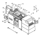
- FIG. 1 shows a component mounter 10.
- the component mounter 10 is a device for performing a component mounting operation on the circuit substrate 12.
- the component mounting machine 10 includes an apparatus main body 20, a base material conveyance holding device 22, a component mounting device 24, a mark camera 26, a parts camera 28, a component supply device 30, a loose component supply device 32, a display device 33, a cut and clinching device ( 3) 34 and a control device (see FIG. 7) 36.
- the circuit substrate 12 includes a circuit board, a three-dimensional structure substrate, and the like, and the circuit board includes a printed wiring board and a printed circuit board.
- the apparatus main body 20 includes a frame portion 40 and a beam portion 42 that is overlaid on the frame portion 40.
- the substrate conveyance holding device 22 is disposed in the center of the frame portion 40 in the front-rear direction, and includes a conveyance device 50 and a clamp device 52.
- the conveyance device 50 is a device that conveys the circuit substrate 12
- the clamp device 52 is a device that holds the circuit substrate 12.
- the base material transport and holding device 22 transports the circuit base material 12 and holds the circuit base material 12 fixedly at a predetermined position.
- the conveyance direction of the circuit substrate 12 is referred to as an X direction
- a horizontal direction perpendicular to the direction is referred to as a Y direction
- a vertical direction is referred to as a Z direction. That is, the width direction of the component mounting machine 10 is the X direction, and the front-rear direction is the Y direction.
- the component mounting device 24 is disposed in the beam portion 42 and includes two work heads 60 and 62 and a work head moving device 64. As shown in FIG. 2, a suction nozzle 66 is provided at the lower end surface of each work head 60, 62, and the parts are sucked and held by the suction nozzle 66.
- the work head moving device 64 includes an X direction moving device 68, a Y direction moving device 70, and a Z direction moving device 72. Then, the two working heads 60 and 62 are integrally moved to arbitrary positions on the frame portion 40 by the X-direction moving device 68 and the Y-direction moving device 70.
- the work heads 60 and 62 are detachably attached to the sliders 74 and 76, and the Z-direction moving device 72 individually moves the sliders 74 and 76 in the vertical direction. That is, the work heads 60 and 62 are individually moved in the vertical direction by the Z-direction moving device 72.
- the mark camera 26 is attached to the slider 74 so as to face downward, and is moved together with the work head 60 in the X direction, the Y direction, and the Z direction. As a result, the mark camera 26 images an arbitrary position on the frame unit 40. As shown in FIG. 1, the parts camera 28 is disposed between the base material conveyance holding device 22 and the component supply device 30 on the frame portion 40 so as to face upward. Thereby, the parts camera 28 images the parts gripped by the suction nozzles 66 of the work heads 60 and 62.
- the component supply device 30 is disposed at one end of the frame portion 40 in the front-rear direction.
- the component supply device 30 includes a tray-type component supply device 78 and a feeder-type component supply device (see FIG. 7) 80.
- the tray-type component supply device 78 is a device that supplies components placed on the tray.
- the feeder-type component supply device 80 is a device that supplies components by a tape feeder or a stick feeder (not shown).
- the bulk component supply device 32 is disposed at the other end portion of the frame portion 40 in the front-rear direction.
- the separated component supply device 32 is a device for aligning a plurality of components scattered in a separated state and supplying the components in an aligned state. That is, it is an apparatus that aligns a plurality of components in an arbitrary posture into a predetermined posture and supplies the components in a predetermined posture.
- a display device 33 is disposed at the end of the bulk component supply device 32. The display device 33 displays information related to component mounting work by the component mounter 10.
- components supplied by the component supply device 30 and the bulk component supply device 32 include electronic circuit components, solar cell components, and power module components.
- Electronic circuit components include components having leads and components not having leads.
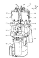
- the cut and clinching device 34 is disposed below the conveying device 50, and includes a cut and clinching unit 100 and a unit moving device 102 as shown in FIG.
- the cut and clinching unit 100 includes a unit body 110, a pair of slide bodies 112, and a pitch changing mechanism 114.
- a slide rail 116 is disposed at the upper end of the unit main body 110 so as to extend in the X direction.
- the pair of slide bodies 112 are slidably supported by the slide rail 116.
- the pitch changing mechanism 114 includes an electromagnetic motor 118, and the distance between the pair of slide bodies 112 is controlled to be controllable by the operation of the electromagnetic motor 118.
- each of the pair of slide bodies 112 includes a main body portion 120, a movable portion 122, and a slide device 124, and is slidably held on the slide rail 116 in the main body portion 120.
- Two slide rails 126 are fixed to the back side of the main body 120 so as to extend in the X direction, and the movable portion 122 is slidably held by the two slide rails 126.
- the slide device 124 includes an electromagnetic motor (see FIG. 7) 128, and the movable portion 122 slides in a controllable manner by the operation of the electromagnetic motor 128.
- the upper end portion of the main body 120 has a tapered shape, and a first insertion hole 130 is formed so as to penetrate the upper end portion in the vertical direction.
- the first insertion hole 130 opens at the upper end to the upper end surface of the main body 120 and opens to the side of the main body 120 at the lower end.
- the opening edge to the upper end surface of the main-body part 120 of the 1st insertion hole 130 is made into the fixed blade 131 (refer FIG. 8).
- a disposal box 132 is disposed below the opening of the first insertion hole 130 to the side surface of the main body 120.
- the upper end portion of the movable portion 122 is also tapered, and a bent portion 133 bent in an L shape is formed at the upper end portion.
- the bent portion 133 extends above the upper end surface of the main body 120, and the bent portion 133 and the upper end of the main body 120 face each other with a slight clearance.
- the first insertion hole 130 that opens to the upper end surface of the main body 120 is covered with the bent portion 133, but the second insertion hole 136 is disposed in the bent portion 133 so as to face the first insertion hole 130. Is formed.
- the second insertion hole 136 is a through-hole penetrating the bent portion 133 in the vertical direction, and the inner peripheral surface of the second insertion hole 136 is a tapered surface whose inner diameter decreases toward the lower side.
- the inner peripheral surface of the first insertion hole 130 in the vicinity of the opening to the upper end surface of the main body 120 is not a tapered surface, and the inner diameter in the vicinity of the opening of the first insertion hole 130 is generally uniform.
- the opening edge of the second insertion hole 136 toward the lower end surface of the bent portion 133 is a movable blade (see FIG. 8) 138.
- a guide groove 140 is formed on the upper end surface of the bent portion 133 so as to extend in the X-axis direction. The guide groove 140 is formed so as to straddle the opening of the second insertion hole 136, and the guide groove 140 and the second insertion hole 136 are connected.
- the movable part 122 includes a movable first part 144 and a movable second part 146.
- the movable first portion 144 constitutes a lower portion of the movable portion 122 and is slidably supported by a slide rail 126 as shown in FIG.
- the movable second portion 146 constitutes an upper portion of the movable portion 122 and includes a bent portion 133.
- the movable second portion 146 is bolted to the movable first portion 144, and the movable second portion 146 can be removed from the movable first portion 144 by removing the bolt.
- the main body 120 is also composed of a main body first part 147 and a main body second part 148.
- the main body first portion 147 constitutes a lower portion of the main body portion 120 and is slidably supported by the slide rail 116 as shown in FIG.
- the main body second portion 148 constitutes an upper portion of the main body portion 120, and a first insertion hole 130 is formed therein.
- the main body second portion 148 is bolted to the main body first portion 147, and the main body second portion 148 can be removed from the main body first portion 147 by removing the bolt.
- the unit moving device 102 includes an X-direction moving device 150, a Y-direction moving device 152, a Z-direction moving device 154, and a rotation device 156.
- the X direction moving device 150 includes a slide rail 160 and an X slider 162.
- the slide rail 160 is disposed so as to extend in the X direction, and the X slider 162 is slidably held by the slide rail 160.
- the X slider 162 moves in the X direction by driving an electromagnetic motor (see FIG. 7) 164.
- the Y-direction moving device 152 includes a slide rail 166 and a Y slider 168.
- the slide rail 166 is disposed on the X slider 162 so as to extend in the Y direction, and the Y slider 168 is slidably held on the slide rail 166.
- the Y slider 168 moves in the Y direction by driving an electromagnetic motor (see FIG. 7) 170.
- the Z direction moving device 154 includes a slide rail 172 and a Z slider 174.
- the slide rail 172 is disposed on the Y slider 168 so as to extend in the Z direction, and the Z slider 174 is slidably held on the slide rail 172.
- the Z slider 174 moves in the Z direction by driving an electromagnetic motor (see FIG. 7) 176.
- the rotation device 156 has a generally disk-shaped rotary table 178.
- the rotary table 178 is supported by the Z slider 174 so as to be rotatable about its axis, and is rotated by driving of an electromagnetic motor (see FIG. 7) 180.
- a cut and clinching unit 100 is disposed on the rotary table 178.
- the cut and clinch unit 100 is moved to an arbitrary position by the X-direction moving device 150, the Y-direction moving device 152, and the Z-direction moving device 154, and is rotated at an arbitrary angle by the rotation device 156.
- the second insertion hole 136 of the cut-and-clinch unit 100 can be positioned at an arbitrary position below the circuit substrate 12 held by the clamp device 52.
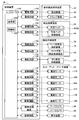
- the control device 36 includes a controller 190, a plurality of drive circuits 192, a control circuit 194, and an image processing device 196.
- the plurality of drive circuits 192 include the transport device 50, the clamp device 52, the work heads 60 and 62, the work head moving device 64, the tray-type component supply device 78, the feeder-type component supply device 80, the bulk component supply device 32, and the electromagnetic motor. 118, 128, 164, 170, 176, 180.
- the controller 190 includes a CPU, a ROM, a RAM, and the like, mainly a computer, and is connected to a plurality of drive circuits 192.
- the controller 190 is connected to the display device 33 via the control circuit 194, and a predetermined image is displayed on the display device 33 by the controller 190. Further, the controller 190 is also connected to the image processing device 196.
- the image processing device 196 processes image data obtained by the mark camera 26 and the part camera 28, and the controller 190 acquires various types of information from the image data.
- the component mounting operation is performed on the circuit substrate 12 held by the substrate conveyance holding device 22 with the above-described configuration.
- various components can be mounted on the circuit substrate 12, but a component having a lead (hereinafter, may be abbreviated as “lead component”) is used as the circuit substrate 12. The case of mounting will be described below.
- the circuit substrate 12 is transported to the working position, and is fixedly held by the clamp device 52 at that position.
- the mark camera 26 moves above the circuit substrate 12 and images the circuit substrate 12.
- the component supply device 30 or the bulk component supply device 32 supplies lead components at a predetermined supply position.
- one of the work heads 60 and 62 moves above the component supply position, and holds the component by the suction nozzle 66.
- the lead component 200 includes a component main body portion 202 and two leads 204 extending from the bottom surface of the component main body portion 202. The lead component 200 is sucked and held in the component main body 202 by the suction nozzle 66.
- the work heads 60 and 62 holding the lead component 200 move above the parts camera 28, and the lead component 200 held by the suction nozzle 66 is imaged by the parts camera 28. As a result, information on the holding position of the component can be obtained.
- the work heads 60 and 62 holding the lead component 200 move above the circuit substrate 12 to correct an error in the holding position of the circuit substrate 12, an error in the holding position of the component, and the like.
- the two leads 204 of the lead component 200 sucked and held by the suction nozzle 66 are inserted into the two through holes 208 formed in the circuit substrate 12. At this time, the cut and clinching unit 100 is moved below the circuit substrate 12.
- the cut-and-clinch unit 100 has the coordinates in the XY direction of the second insertion hole 136 of the movable portion 122 and the coordinates in the XY direction of the through hole 208 of the circuit base material 12, and The upper surface and the lower surface of the circuit substrate 12 are not in contact with each other, and the upper surface of the movable portion 122 is moved so as to be located slightly below the lower surface of the circuit substrate 12.
- the distance between the second insertion holes 136 of the movable portion 122 of the pair of slide bodies 112 is between the two through holes 208 formed in the circuit substrate 12.
- the distance between the pair of slide bodies 112 is adjusted by the pitch changing mechanism 114 so as to be the same as the distance.
- the cut and clinch unit 100 is moved and rotated in the XYZ directions.
- the coordinate in the XY direction of the second insertion hole 136 of the movable portion 122 and the coordinate in the XY direction of the through hole 208 of the circuit base material 12 coincide with each other, and the upper surface of the movable portion 122 and the circuit base material 12 are matched.
- the upper surface of the movable part 122 is positioned slightly below the lower surface of the circuit substrate 12.
- the tip of the lead 204 is cut and clinched as shown in FIG. It is inserted into the first insertion hole 130 of the main body 120 through the second insertion hole 136 of the movable part 122 of the unit 100.
- the inner peripheral surface of the second insertion hole 136 positioned below the through hole 208 is a tapered surface, even if the lead 204 is bent to some extent, the first end portion of the lead 204 is The introduction into the two insertion holes 136 can be appropriately secured.
- the movable portion 122 slides by the operation of the slide device 124.
- the lead 204 is cut by the fixed blade 131 of the first insertion hole 130 and the movable blade 138 of the second insertion hole 136, as shown in FIG.
- the tip portion separated by cutting the lead 204 falls inside the first insertion hole 130 and is discarded in the disposal box 132.
- the new tip portion of the lead 204 by cutting is bent along the tapered surface of the inner periphery of the second insertion hole 136 as the movable portion 122 slides, and further, the movable portion 122 slides.
- the leading end of the lead 204 is bent along the guide groove 140.
- the lead component 200 is mounted on the circuit substrate 12 in a state in which the lead 204 is prevented from coming off from the through hole 208.
- the lead component 200 is mounted on the circuit substrate 12 by the lead 204 being cut and bent by the cut and clinching device 34.
- the lead 204 is cut and bent by the cut-and-clinch device 34, the lead 204 is inserted into the first insertion hole 130 and the second insertion hole 136.
- the first insertion hole 130 and the second insertion hole 136 has a shape corresponding to the wire diameter of the lead 204. Therefore, a plurality of types of main body second part of the main body part 120 and movable second part of the movable part 122 are prepared according to the wire diameter of the lead 204, and the lead component 200 to be mounted is changed. In this case, the main body second part and the movable second part are changed according to the wire diameter of the lead 204.
- a movable second part 146 shown in FIG. 6 and a movable second part (see FIG. 10) 210 different from the main body second part 148 and a main body second part (see FIG. 10) 212 are: It is prepared.
- the movable second portion 210 has substantially the same shape as the movable second portion 146 except for the second insertion hole 214.
- the main body second portion 212 has substantially the same shape as the main body second portion 148 except for the first insertion hole 216. Therefore, when the lead component 200 having the second insertion hole 214 and the lead 204 having a wire diameter corresponding to the first insertion hole 216 is a component to be mounted, the movable second portion 146 is movable first.
- the movable second portion 210 is attached to the movable first portion 144 instead of the movable second portion 146 after being removed from the portion 144.
- the main body second part 148 is removed from the main body first part 147, and the main body second part 212 is attached to the main body first part 147 instead of the main body second part 148.
- a movable second part 220 and a main body second part 222 having the shape shown in FIG. 11 are also prepared.
- the movable second portion 220 has two second insertion holes 224 and 226 formed therein.
- the main body second portion 222 is formed with a first insertion hole 228 having a shape corresponding to the second insertion holes 224 and 226. Then, in a state where the second insertion hole 224 and the first insertion hole 228 are overlapped, the movable second portion 220 slides in one direction of the X direction. For this reason, when the lead 204 is inserted into the second insertion hole 224 and the first insertion hole 228 and the movable second portion 220 is slid, the lead 204 is cut and bent in one direction.
- the movable second portion 220 slides in the other direction of the X direction. For this reason, when the lead 204 is inserted into the second insertion hole 226 and the first insertion hole 228 and the movable second portion 220 is slid, the lead 204 is cut and bent in the other direction. That is, according to the movable second portion 220 and the main body second portion 222, the lead 204 can be bent in any direction of one of the X direction and the other.
- the movable second portion 220 is attached to the movable first portion 144 instead of the movable second portion 146, and the main body second portion 148 is replaced with the main body second portion 148.
- the two parts 222 are attached to the main body first part 147.
- the movable second portion and the main body second portion are exchanged in accordance with the wire diameter of the lead 204 of the lead component 200 to be mounted, the bending direction of the lead 204, and the like.
- the movable second part to be attached and the movable second part different from the main body second part and the main body second part are:
- the movable first portion 144 and the main body first portion 147 are attached.
- a recognition mark (see FIGS. 6, 10, and 11) 230 is written on each of the movable second parts 146, 210, and 220 and the main body second parts 148, 212, and 222.
- the movable first part 144, the movable second parts 146, 210, 220 attached to the main body first part 147 and the main body second parts 148, 212, 222 are displayed. Confirmation is performed.
- the movable second portions 146, 210, and 220 are configured by a base portion 234 and a standing portion 235.
- the base part 234 is a place fixed to the movable first part 144, and the standing part 235 is erected so as to extend upward on the upper surface of the base part 234.
- a bent portion 133 is formed at the upper end portion of the standing portion 235, and second insertion holes 136, 214, 224, and 226 are formed in the bent portion 133.
- the main body second parts 148, 212, and 222 include a base part 236 and a standing part 238.
- the base portion 236 is a place fixed to the main body first portion 147, and the standing portion 238 is erected so as to extend upward on the upper surface of the base portion 236. Note that first insertion holes 130, 216, and 228 are opened on the upper surface of the standing portion 238.
- a recognition mark 230 is written on the upper surface of the base portion 234 of the movable second portions 146, 210, and 220 and the upper surface of the base portion 236 of the main body second portions 148, 212, and 222.
- the recognition mark 230 is composed of two concave portions 240 and 242.
- the two recesses 240 and 242 are imaged by the mark camera 26, and the imaged data is analyzed by the controller 190.
- the mark camera 26 is for imaging the circuit board 12 and is adjusted so that the focus is on the circuit board 12.
- the base parts 234 and 236 on which the recognition mark 230 is written are located below the circuit base material 12, and the distance between the circuit base material 12 and the base parts 234 and 236 is set up by the standing part 235. , 238 is longer than the vertical dimension. For this reason, the recognition mark 230 is located outside the range of the depth of field of the mark camera 26, and it is difficult to obtain a clear image of the recognition mark 230 by the mark camera 26.
- the controller 190 analyzes the imaging data of the two concave portions 240 and 242, and the relative positions of the two concave portions 240 and 242 in the X direction and the Y direction, and the two concave portions 240 and 242. The distance between them (separation distance) is calculated.
- the controller 190 associates the types of the movable second parts 146, 210, and 220 and the main body second parts 148, 212, and 222 with the relative positions and the separation distances of the concave parts 240 and 242, and maps data. Is remembered as For this reason, in the controller 190, the types of the movable second portions 146, 210, and 220 and the main body second portions 148, 212, and 222 that match the calculated relative positions and separation distances of the concave portions 240 and 242 are mapped. Extracted from the data. Then, the movable first part 144, the movable second parts 146, 210 and 220 attached to the main body first part 147, and the main body second parts 148, 212 and 222 are confirmed.
- the display device 33 displays a comment notifying that effect and information regarding the types of the movable second parts 146, 210, and 220 and the main body second parts 148, 212, and 222 according to the mounting work. Is done.
- the movable first part 144, the movable second parts 146, 210, 220 attached to the main body first part 147, and the main body first By confirming the two parts 148, 212, and 222, an installation error by an operator is prevented.
- the confirmation work of the movable second parts 146, 210, 220 and the main body second parts 148, 212, 222 is performed when a start switch for starting the component mounting machine 10 is operated, and a new production program is started. This is executed at a timing before the new circuit board is carried into the component mounter 10.
- the movable second parts 146, 210, and 220 and the main body second parts 148, 212, and 222 of a type different from the type according to the mounting work are attached to the movable first part 144 and the main body first part 147.
- a comment notifying that effect is displayed on the display device 33, so that it is possible to prevent the start of a new production program and the introduction of a new circuit board.
- the controller 190 of the control device 36 includes an imaging unit 250 and a recognition unit 252 as shown in FIG.
- the imaging unit 250 is a functional unit for imaging the recognition mark 230 by the mark camera 26.
- the recognition unit 252 is a functional unit for recognizing the types of the movable second units 146, 210, and 220 and the main body second units 148, 212, and 222 based on the imaging data.
- the component mounting machine 10 is an example of a substrate working machine.
- the mark camera 26 is an example of an imaging device.
- the cut and clinching device 34 is an example of a cutting device.
- the control device 36 is an example of a control device.
- the first insertion holes 130, 216, and 228 are examples of insertion holes.
- the second insertion holes 136, 214, 224, and 226 are examples of insertion holes.
- the movable first part 144 is an example of a main body part.
- the movable second parts 146, 210, and 220 are examples of cutting tools.
- the main body first portion 147 is an example of a main body portion.
- the main body second parts 148, 212, and 222 are examples of cutting tools.
- the lead component 200 is an example of a lead component.
- the lead 204 is an example of a lead.
- the recognition mark 230 is an example of a recognition mark.
- the recesses 240 and 242 are examples of symbols.
- the imaging unit 250 is an example of an imaging unit.
- the recognition unit 252 is an example of a recognition unit.
- the process executed by the imaging unit 250 is an example of an imaging process.
- the process executed by the recognition unit 252 is an example of a recognition process.
- this invention is not limited to the said Example, It is possible to implement in the various aspect which gave various change and improvement based on the knowledge of those skilled in the art.
- the concave portions 240 and 242 are employed as the recognition marks 230 written on the movable second portions 146, 210 and 220 and the main body second portions 148, 212 and 222.
- various shapes such as ⁇ , ⁇ , ⁇ , and a star shape can be adopted.
- the types of the movable second parts 146, 210, and 220 and the main body second parts 148, 212, and 222 are recognized based on the positional relationship between the two recesses 240 and 242.
- the types of the movable second parts 146, 210, 220 and the main body second parts 148, 212, 222 may be recognized based on the contrast, color, etc. of the recesses 240, 242. More specifically, a 2D code or the like can be adopted as the recognition mark 230. However, when a 2D code or the like is employed, it is necessary to write the 2D code or the like within the depth of field of the mark camera 26.
Landscapes
- Engineering & Computer Science (AREA)
- Physics & Mathematics (AREA)
- Manufacturing & Machinery (AREA)
- Microelectronics & Electronic Packaging (AREA)
- Electromagnetism (AREA)
- Artificial Intelligence (AREA)
- Health & Medical Sciences (AREA)
- General Health & Medical Sciences (AREA)
- Toxicology (AREA)
- Computer Vision & Pattern Recognition (AREA)
- General Physics & Mathematics (AREA)
- Theoretical Computer Science (AREA)
- Operations Research (AREA)
- Supply And Installment Of Electrical Components (AREA)
Abstract
Priority Applications (5)
| Application Number | Priority Date | Filing Date | Title |
|---|---|---|---|
| EP15897114.3A EP3319408B1 (fr) | 2015-06-30 | 2015-06-30 | Machine de travail sur substrats et procédé de reconnaissance |
| PCT/JP2015/068763 WO2017002187A1 (fr) | 2015-06-30 | 2015-06-30 | Machine de travail sur substrats et procédé de reconnaissance |
| CN201580081200.7A CN108029231B (zh) | 2015-06-30 | 2015-06-30 | 对基板作业机及识别方法 |
| US15/735,217 US10178820B2 (en) | 2015-06-30 | 2015-06-30 | Board work machine and recognition method |
| JP2017525712A JP6648133B2 (ja) | 2015-06-30 | 2015-06-30 | 対基板作業機、および認識方法 |
Applications Claiming Priority (1)
| Application Number | Priority Date | Filing Date | Title |
|---|---|---|---|
| PCT/JP2015/068763 WO2017002187A1 (fr) | 2015-06-30 | 2015-06-30 | Machine de travail sur substrats et procédé de reconnaissance |
Publications (1)
| Publication Number | Publication Date |
|---|---|
| WO2017002187A1 true WO2017002187A1 (fr) | 2017-01-05 |
Family
ID=57608147
Family Applications (1)
| Application Number | Title | Priority Date | Filing Date |
|---|---|---|---|
| PCT/JP2015/068763 WO2017002187A1 (fr) | 2015-06-30 | 2015-06-30 | Machine de travail sur substrats et procédé de reconnaissance |
Country Status (5)
| Country | Link |
|---|---|
| US (1) | US10178820B2 (fr) |
| EP (1) | EP3319408B1 (fr) |
| JP (1) | JP6648133B2 (fr) |
| CN (1) | CN108029231B (fr) |
| WO (1) | WO2017002187A1 (fr) |
Cited By (1)
| Publication number | Priority date | Publication date | Assignee | Title |
|---|---|---|---|---|
| CN110603910A (zh) * | 2017-05-12 | 2019-12-20 | 株式会社富士 | 元件插入机以及引脚切断方法 |
Families Citing this family (5)
| Publication number | Priority date | Publication date | Assignee | Title |
|---|---|---|---|---|
| CN108353528B (zh) * | 2015-10-06 | 2020-07-03 | 株式会社富士 | 切断/弯折装置 |
| US10813259B2 (en) * | 2015-11-18 | 2020-10-20 | Fuji Corporation | Board work machine and insertion method |
| JP6858776B2 (ja) * | 2016-07-20 | 2021-04-14 | 株式会社Fuji | 対基板作業機 |
| EP3795271B1 (fr) * | 2018-05-14 | 2023-05-24 | FUJI Corporation | Dispositif de montage avec une unité de coupe de fil conducteur |
| JP7423355B2 (ja) * | 2020-03-04 | 2024-01-29 | 株式会社Fuji | 実装機 |
Citations (4)
| Publication number | Priority date | Publication date | Assignee | Title |
|---|---|---|---|---|
| JP2004327570A (ja) * | 2003-04-23 | 2004-11-18 | Fuji Mach Mfg Co Ltd | 電子部品実装機のフィーダ管理システム |
| JP2006351682A (ja) * | 2005-06-14 | 2006-12-28 | Yamagata Casio Co Ltd | 電子部品搭載装置及びそのノズル段取方法 |
| JP2009117734A (ja) * | 2007-11-09 | 2009-05-28 | Panasonic Corp | 電子部品実装装置およびノズル装着履歴データ管理方法 |
| WO2015063827A1 (fr) * | 2013-10-28 | 2015-05-07 | 富士機械製造株式会社 | Dispositif de découpe et de sertissage de fil conducteur |
Family Cites Families (8)
| Publication number | Priority date | Publication date | Assignee | Title |
|---|---|---|---|---|
| JPS6062944A (ja) * | 1983-09-16 | 1985-04-11 | Teruaki Shimazu | 滋養痩身茶 |
| JP2989583B2 (ja) * | 1998-06-26 | 1999-12-13 | 三洋電機株式会社 | 部品装着装置 |
| US6123488A (en) * | 1998-12-23 | 2000-09-26 | Kennametal Inc. | Cutting insert with universal identification |
| JP3776323B2 (ja) | 2001-02-28 | 2006-05-17 | Tdk株式会社 | 電子部品リード線のカットアンドクリンチ装置および電子部品挿入装置 |
| JP2002280798A (ja) * | 2001-03-22 | 2002-09-27 | Yamagata Casio Co Ltd | ノズル種類認識制御方法およびノズル汚れ認識制御方法並びにそれら制御方法を用いた電子部品搭載装置 |
| JP4973630B2 (ja) * | 2008-09-10 | 2012-07-11 | パナソニック株式会社 | ノズル識別装置、部品実装機、ノズル識別方法及び部品実装方法 |
| US8746115B2 (en) * | 2012-01-09 | 2014-06-10 | Iscar, Ltd. | Cutting insert having hole orientation indicia and method for making thereof |
| JP6131045B2 (ja) * | 2012-12-28 | 2017-05-17 | Juki株式会社 | 電子部品実装装置及び電子部品実装方法 |
-
2015
- 2015-06-30 WO PCT/JP2015/068763 patent/WO2017002187A1/fr active Application Filing
- 2015-06-30 JP JP2017525712A patent/JP6648133B2/ja active Active
- 2015-06-30 CN CN201580081200.7A patent/CN108029231B/zh active Active
- 2015-06-30 US US15/735,217 patent/US10178820B2/en active Active
- 2015-06-30 EP EP15897114.3A patent/EP3319408B1/fr active Active
Patent Citations (4)
| Publication number | Priority date | Publication date | Assignee | Title |
|---|---|---|---|---|
| JP2004327570A (ja) * | 2003-04-23 | 2004-11-18 | Fuji Mach Mfg Co Ltd | 電子部品実装機のフィーダ管理システム |
| JP2006351682A (ja) * | 2005-06-14 | 2006-12-28 | Yamagata Casio Co Ltd | 電子部品搭載装置及びそのノズル段取方法 |
| JP2009117734A (ja) * | 2007-11-09 | 2009-05-28 | Panasonic Corp | 電子部品実装装置およびノズル装着履歴データ管理方法 |
| WO2015063827A1 (fr) * | 2013-10-28 | 2015-05-07 | 富士機械製造株式会社 | Dispositif de découpe et de sertissage de fil conducteur |
Non-Patent Citations (1)
| Title |
|---|
| See also references of EP3319408A4 * |
Cited By (2)
| Publication number | Priority date | Publication date | Assignee | Title |
|---|---|---|---|---|
| CN110603910A (zh) * | 2017-05-12 | 2019-12-20 | 株式会社富士 | 元件插入机以及引脚切断方法 |
| EP3624577A4 (fr) * | 2017-05-12 | 2020-05-06 | Fuji Corporation | Machine d'insertion de composant et procédé de coupe de patte |
Also Published As
| Publication number | Publication date |
|---|---|
| EP3319408B1 (fr) | 2021-12-29 |
| JP6648133B2 (ja) | 2020-02-14 |
| EP3319408A1 (fr) | 2018-05-09 |
| CN108029231A (zh) | 2018-05-11 |
| JPWO2017002187A1 (ja) | 2018-04-12 |
| EP3319408A4 (fr) | 2018-09-05 |
| US20180184553A1 (en) | 2018-06-28 |
| CN108029231B (zh) | 2020-03-06 |
| US10178820B2 (en) | 2019-01-08 |
Similar Documents
| Publication | Publication Date | Title |
|---|---|---|
| JP6619019B2 (ja) | 対基板作業システム、および挿入方法 | |
| WO2017002187A1 (fr) | Machine de travail sur substrats et procédé de reconnaissance | |
| WO2017060974A1 (fr) | Dispositif de découpe/pliage et dispositif de découpe | |
| WO2016199289A1 (fr) | Machine d'usinage de substrat et procédé de reconnaissance | |
| WO2018029844A1 (fr) | Machine d'usinage de substrat | |
| JP7242920B2 (ja) | 切断・屈曲装置 | |
| WO2017081724A1 (fr) | Appareil de cintrage | |
| JP7010980B2 (ja) | 切断・屈曲方法 | |
| JP6678178B2 (ja) | 作業機 | |
| WO2021186666A1 (fr) | Machine de travail de substrat | |
| WO2018016025A1 (fr) | Machine de travail sur substrat | |
| JP2018148173A (ja) | 対基板作業機 | |
| JP2018014384A (ja) | 対基板作業機 | |
| WO2022064701A1 (fr) | Dispositif de calcul et procédé de cintrage | |
| JPWO2019069438A1 (ja) | 対基板作業システム | |
| JP2017084922A (ja) | 対基板作業システム | |
| JP2023060222A (ja) | 切断・屈曲装置 | |
| JP2021061420A (ja) | 屈曲装置、および屈曲方法 |
Legal Events
| Date | Code | Title | Description |
|---|---|---|---|
| 121 | Ep: the epo has been informed by wipo that ep was designated in this application |
Ref document number: 15897114 Country of ref document: EP Kind code of ref document: A1 |
|
| ENP | Entry into the national phase |
Ref document number: 2017525712 Country of ref document: JP Kind code of ref document: A |
|
| WWE | Wipo information: entry into national phase |
Ref document number: 15735217 Country of ref document: US |
|
| NENP | Non-entry into the national phase |
Ref country code: DE |
|
| WWE | Wipo information: entry into national phase |
Ref document number: 2015897114 Country of ref document: EP |