WO2016208588A1 - Procédé de fabrication d'un élément électronique organique et procédé de séchage de substrat - Google Patents
Procédé de fabrication d'un élément électronique organique et procédé de séchage de substrat Download PDFInfo
- Publication number
- WO2016208588A1 WO2016208588A1 PCT/JP2016/068416 JP2016068416W WO2016208588A1 WO 2016208588 A1 WO2016208588 A1 WO 2016208588A1 JP 2016068416 W JP2016068416 W JP 2016068416W WO 2016208588 A1 WO2016208588 A1 WO 2016208588A1
- Authority
- WO
- WIPO (PCT)
- Prior art keywords
- substrate
- layer
- organic
- wavelength range
- plastic substrate
- Prior art date
Links
- 239000000758 substrate Substances 0.000 title claims abstract description 377
- 238000000034 method Methods 0.000 title claims abstract description 126
- 238000001035 drying Methods 0.000 title claims abstract description 110
- 238000004519 manufacturing process Methods 0.000 title claims abstract description 58
- 229920003023 plastic Polymers 0.000 claims abstract description 119
- 239000004033 plastic Substances 0.000 claims abstract description 119
- 239000002346 layers by function Substances 0.000 claims abstract description 53
- 230000001678 irradiating effect Effects 0.000 claims abstract description 12
- 239000010410 layer Substances 0.000 claims description 610
- 239000000463 material Substances 0.000 claims description 140
- 238000010438 heat treatment Methods 0.000 claims description 117
- 238000001228 spectrum Methods 0.000 claims description 68
- 230000005855 radiation Effects 0.000 claims description 60
- 239000010409 thin film Substances 0.000 claims description 46
- 238000000862 absorption spectrum Methods 0.000 claims description 28
- 238000006243 chemical reaction Methods 0.000 claims description 20
- 230000008569 process Effects 0.000 claims description 13
- 230000004888 barrier function Effects 0.000 claims description 12
- 238000004804 winding Methods 0.000 claims description 12
- 230000009477 glass transition Effects 0.000 claims description 11
- XLYOFNOQVPJJNP-UHFFFAOYSA-N water Substances O XLYOFNOQVPJJNP-UHFFFAOYSA-N 0.000 claims description 10
- 238000005401 electroluminescence Methods 0.000 claims description 4
- 230000015572 biosynthetic process Effects 0.000 abstract description 33
- 238000000295 emission spectrum Methods 0.000 abstract description 11
- 238000002347 injection Methods 0.000 description 186
- 239000007924 injection Substances 0.000 description 186
- 238000000576 coating method Methods 0.000 description 169
- 239000011248 coating agent Substances 0.000 description 150
- 239000010408 film Substances 0.000 description 150
- 230000005525 hole transport Effects 0.000 description 118
- 238000002474 experimental method Methods 0.000 description 95
- 150000001875 compounds Chemical class 0.000 description 57
- 229920000642 polymer Polymers 0.000 description 56
- -1 polyethylene terephthalate Polymers 0.000 description 50
- 238000012360 testing method Methods 0.000 description 45
- 239000000243 solution Substances 0.000 description 44
- 238000011156 evaluation Methods 0.000 description 41
- 238000010521 absorption reaction Methods 0.000 description 38
- 239000011521 glass Substances 0.000 description 38
- 239000008096 xylene Substances 0.000 description 32
- 239000004065 semiconductor Substances 0.000 description 31
- CTQNGGLPUBDAKN-UHFFFAOYSA-N O-Xylene Chemical compound CC1=CC=CC=C1C CTQNGGLPUBDAKN-UHFFFAOYSA-N 0.000 description 29
- 238000001994 activation Methods 0.000 description 27
- 239000002904 solvent Substances 0.000 description 23
- 239000012298 atmosphere Substances 0.000 description 22
- 230000004913 activation Effects 0.000 description 21
- 239000007788 liquid Substances 0.000 description 21
- 239000000047 product Substances 0.000 description 20
- 230000000694 effects Effects 0.000 description 19
- 229910052751 metal Inorganic materials 0.000 description 19
- 239000002184 metal Substances 0.000 description 19
- 150000002894 organic compounds Chemical group 0.000 description 18
- YXFVVABEGXRONW-UHFFFAOYSA-N Toluene Chemical compound CC1=CC=CC=C1 YXFVVABEGXRONW-UHFFFAOYSA-N 0.000 description 15
- 239000011112 polyethylene naphthalate Substances 0.000 description 15
- 238000005096 rolling process Methods 0.000 description 15
- 238000004528 spin coating Methods 0.000 description 15
- IJGRMHOSHXDMSA-UHFFFAOYSA-N Atomic nitrogen Chemical compound N#N IJGRMHOSHXDMSA-UHFFFAOYSA-N 0.000 description 14
- 229940125904 compound 1 Drugs 0.000 description 14
- 229920003207 poly(ethylene-2,6-naphthalate) Polymers 0.000 description 14
- 238000004132 cross linking Methods 0.000 description 13
- BASFCYQUMIYNBI-UHFFFAOYSA-N platinum Chemical compound [Pt] BASFCYQUMIYNBI-UHFFFAOYSA-N 0.000 description 13
- 125000003118 aryl group Chemical group 0.000 description 12
- QVGXLLKOCUKJST-UHFFFAOYSA-N atomic oxygen Chemical compound [O] QVGXLLKOCUKJST-UHFFFAOYSA-N 0.000 description 12
- 229910052760 oxygen Inorganic materials 0.000 description 12
- 239000001301 oxygen Substances 0.000 description 12
- 229920000123 polythiophene Polymers 0.000 description 12
- 230000002829 reductive effect Effects 0.000 description 12
- 150000004982 aromatic amines Chemical group 0.000 description 11
- 238000010835 comparative analysis Methods 0.000 description 11
- 125000000623 heterocyclic group Chemical group 0.000 description 11
- 239000011368 organic material Substances 0.000 description 10
- 229920000767 polyaniline Polymers 0.000 description 10
- YMWUJEATGCHHMB-UHFFFAOYSA-N Dichloromethane Chemical compound ClCCl YMWUJEATGCHHMB-UHFFFAOYSA-N 0.000 description 9
- 229910052783 alkali metal Inorganic materials 0.000 description 9
- 238000012545 processing Methods 0.000 description 9
- OKTJSMMVPCPJKN-UHFFFAOYSA-N Carbon Chemical compound [C] OKTJSMMVPCPJKN-UHFFFAOYSA-N 0.000 description 8
- KDLHZDBZIXYQEI-UHFFFAOYSA-N Palladium Chemical compound [Pd] KDLHZDBZIXYQEI-UHFFFAOYSA-N 0.000 description 8
- 239000002253 acid Substances 0.000 description 8
- 150000001340 alkali metals Chemical class 0.000 description 8
- 230000000903 blocking effect Effects 0.000 description 8
- 229940125782 compound 2 Drugs 0.000 description 8
- 239000000178 monomer Substances 0.000 description 8
- 229920001296 polysiloxane Polymers 0.000 description 8
- 229910052757 nitrogen Inorganic materials 0.000 description 7
- 229960003540 oxyquinoline Drugs 0.000 description 7
- 229910052697 platinum Inorganic materials 0.000 description 7
- 229920003227 poly(N-vinyl carbazole) Polymers 0.000 description 7
- 229920002098 polyfluorene Polymers 0.000 description 7
- 239000011698 potassium fluoride Substances 0.000 description 7
- 238000004544 sputter deposition Methods 0.000 description 7
- 239000000126 substance Substances 0.000 description 7
- 125000001424 substituent group Chemical group 0.000 description 7
- 238000012546 transfer Methods 0.000 description 7
- 230000037303 wrinkles Effects 0.000 description 7
- ZWEHNKRNPOVVGH-UHFFFAOYSA-N 2-Butanone Chemical compound CCC(C)=O ZWEHNKRNPOVVGH-UHFFFAOYSA-N 0.000 description 6
- 229910000838 Al alloy Inorganic materials 0.000 description 6
- HEDRZPFGACZZDS-UHFFFAOYSA-N Chloroform Chemical compound ClC(Cl)Cl HEDRZPFGACZZDS-UHFFFAOYSA-N 0.000 description 6
- RYGMFSIKBFXOCR-UHFFFAOYSA-N Copper Chemical compound [Cu] RYGMFSIKBFXOCR-UHFFFAOYSA-N 0.000 description 6
- XEKOWRVHYACXOJ-UHFFFAOYSA-N Ethyl acetate Chemical compound CCOC(C)=O XEKOWRVHYACXOJ-UHFFFAOYSA-N 0.000 description 6
- OKKJLVBELUTLKV-UHFFFAOYSA-N Methanol Chemical compound OC OKKJLVBELUTLKV-UHFFFAOYSA-N 0.000 description 6
- BQCADISMDOOEFD-UHFFFAOYSA-N Silver Chemical compound [Ag] BQCADISMDOOEFD-UHFFFAOYSA-N 0.000 description 6
- WYURNTSHIVDZCO-UHFFFAOYSA-N Tetrahydrofuran Chemical compound C1CCOC1 WYURNTSHIVDZCO-UHFFFAOYSA-N 0.000 description 6
- XLOMVQKBTHCTTD-UHFFFAOYSA-N Zinc monoxide Chemical compound [Zn]=O XLOMVQKBTHCTTD-UHFFFAOYSA-N 0.000 description 6
- 229910052784 alkaline earth metal Inorganic materials 0.000 description 6
- 150000001342 alkaline earth metals Chemical class 0.000 description 6
- 125000000217 alkyl group Chemical group 0.000 description 6
- 229910045601 alloy Inorganic materials 0.000 description 6
- 239000000956 alloy Substances 0.000 description 6
- 229910052782 aluminium Inorganic materials 0.000 description 6
- 229920001940 conductive polymer Polymers 0.000 description 6
- 229910052802 copper Inorganic materials 0.000 description 6
- 239000010949 copper Substances 0.000 description 6
- 238000010586 diagram Methods 0.000 description 6
- 229910001873 dinitrogen Inorganic materials 0.000 description 6
- 239000002019 doping agent Substances 0.000 description 6
- PCHJSUWPFVWCPO-UHFFFAOYSA-N gold Chemical compound [Au] PCHJSUWPFVWCPO-UHFFFAOYSA-N 0.000 description 6
- 229910052737 gold Inorganic materials 0.000 description 6
- 239000010931 gold Substances 0.000 description 6
- PQXKHYXIUOZZFA-UHFFFAOYSA-M lithium fluoride Chemical compound [Li+].[F-] PQXKHYXIUOZZFA-UHFFFAOYSA-M 0.000 description 6
- 238000005259 measurement Methods 0.000 description 6
- 150000004706 metal oxides Chemical class 0.000 description 6
- 229920000553 poly(phenylenevinylene) Polymers 0.000 description 6
- 229920000548 poly(silane) polymer Polymers 0.000 description 6
- 229920005596 polymer binder Polymers 0.000 description 6
- 239000002491 polymer binding agent Substances 0.000 description 6
- 229910052709 silver Inorganic materials 0.000 description 6
- 239000004332 silver Substances 0.000 description 6
- XOLBLPGZBRYERU-UHFFFAOYSA-N tin dioxide Chemical compound O=[Sn]=O XOLBLPGZBRYERU-UHFFFAOYSA-N 0.000 description 6
- 229910001887 tin oxide Inorganic materials 0.000 description 6
- CSCPPACGZOOCGX-UHFFFAOYSA-N Acetone Chemical compound CC(C)=O CSCPPACGZOOCGX-UHFFFAOYSA-N 0.000 description 5
- 125000003545 alkoxy group Chemical group 0.000 description 5
- XAGFODPZIPBFFR-UHFFFAOYSA-N aluminium Chemical compound [Al] XAGFODPZIPBFFR-UHFFFAOYSA-N 0.000 description 5
- 125000004432 carbon atom Chemical group C* 0.000 description 5
- 150000004696 coordination complex Chemical class 0.000 description 5
- WASQWSOJHCZDFK-UHFFFAOYSA-N diketene Chemical compound C=C1CC(=O)O1 WASQWSOJHCZDFK-UHFFFAOYSA-N 0.000 description 5
- 239000007772 electrode material Substances 0.000 description 5
- 230000005669 field effect Effects 0.000 description 5
- 229910044991 metal oxide Inorganic materials 0.000 description 5
- 150000002739 metals Chemical class 0.000 description 5
- 150000004866 oxadiazoles Chemical class 0.000 description 5
- 229920005989 resin Polymers 0.000 description 5
- 239000011347 resin Substances 0.000 description 5
- 238000007789 sealing Methods 0.000 description 5
- PUZPDOWCWNUUKD-UHFFFAOYSA-M sodium fluoride Chemical compound [F-].[Na+] PUZPDOWCWNUUKD-UHFFFAOYSA-M 0.000 description 5
- 150000003553 thiiranes Chemical class 0.000 description 5
- 229910001316 Ag alloy Inorganic materials 0.000 description 4
- 229910052693 Europium Inorganic materials 0.000 description 4
- DGAQECJNVWCQMB-PUAWFVPOSA-M Ilexoside XXIX Chemical compound C[C@@H]1CC[C@@]2(CC[C@@]3(C(=CC[C@H]4[C@]3(CC[C@@H]5[C@@]4(CC[C@@H](C5(C)C)OS(=O)(=O)[O-])C)C)[C@@H]2[C@]1(C)O)C)C(=O)O[C@H]6[C@@H]([C@H]([C@@H]([C@H](O6)CO)O)O)O.[Na+] DGAQECJNVWCQMB-PUAWFVPOSA-M 0.000 description 4
- 229910000846 In alloy Inorganic materials 0.000 description 4
- WHXSMMKQMYFTQS-UHFFFAOYSA-N Lithium Chemical compound [Li] WHXSMMKQMYFTQS-UHFFFAOYSA-N 0.000 description 4
- PXHVJJICTQNCMI-UHFFFAOYSA-N Nickel Chemical compound [Ni] PXHVJJICTQNCMI-UHFFFAOYSA-N 0.000 description 4
- 229920001609 Poly(3,4-ethylenedioxythiophene) Polymers 0.000 description 4
- 229920000292 Polyquinoline Polymers 0.000 description 4
- 239000004793 Polystyrene Substances 0.000 description 4
- ZLMJMSJWJFRBEC-UHFFFAOYSA-N Potassium Chemical compound [K] ZLMJMSJWJFRBEC-UHFFFAOYSA-N 0.000 description 4
- 230000003213 activating effect Effects 0.000 description 4
- 150000004056 anthraquinones Chemical class 0.000 description 4
- 125000000732 arylene group Chemical group 0.000 description 4
- 239000011230 binding agent Substances 0.000 description 4
- 229910052792 caesium Inorganic materials 0.000 description 4
- TVFDJXOCXUVLDH-UHFFFAOYSA-N caesium atom Chemical compound [Cs] TVFDJXOCXUVLDH-UHFFFAOYSA-N 0.000 description 4
- 239000011575 calcium Substances 0.000 description 4
- 229910052799 carbon Inorganic materials 0.000 description 4
- 239000011365 complex material Substances 0.000 description 4
- 229940126214 compound 3 Drugs 0.000 description 4
- 239000000975 dye Substances 0.000 description 4
- 238000001704 evaporation Methods 0.000 description 4
- 229910002804 graphite Inorganic materials 0.000 description 4
- 239000010439 graphite Substances 0.000 description 4
- 239000011964 heteropoly acid Substances 0.000 description 4
- 229910052738 indium Inorganic materials 0.000 description 4
- APFVFJFRJDLVQX-UHFFFAOYSA-N indium atom Chemical compound [In] APFVFJFRJDLVQX-UHFFFAOYSA-N 0.000 description 4
- 229910003437 indium oxide Inorganic materials 0.000 description 4
- PJXISJQVUVHSOJ-UHFFFAOYSA-N indium(iii) oxide Chemical compound [O-2].[O-2].[O-2].[In+3].[In+3] PJXISJQVUVHSOJ-UHFFFAOYSA-N 0.000 description 4
- 150000002500 ions Chemical class 0.000 description 4
- 229910052744 lithium Inorganic materials 0.000 description 4
- 239000000203 mixture Substances 0.000 description 4
- 125000001624 naphthyl group Chemical group 0.000 description 4
- AICOOMRHRUFYCM-ZRRPKQBOSA-N oxazine, 1 Chemical compound C([C@@H]1[C@H](C(C[C@]2(C)[C@@H]([C@H](C)N(C)C)[C@H](O)C[C@]21C)=O)CC1=CC2)C[C@H]1[C@@]1(C)[C@H]2N=C(C(C)C)OC1 AICOOMRHRUFYCM-ZRRPKQBOSA-N 0.000 description 4
- 229910052763 palladium Inorganic materials 0.000 description 4
- 125000002080 perylenyl group Chemical group C1(=CC=C2C=CC=C3C4=CC=CC5=CC=CC(C1=C23)=C45)* 0.000 description 4
- 125000001997 phenyl group Chemical group [H]C1=C([H])C([H])=C(*)C([H])=C1[H] 0.000 description 4
- 229920000128 polypyrrole Polymers 0.000 description 4
- 229920002223 polystyrene Polymers 0.000 description 4
- 229910052700 potassium Inorganic materials 0.000 description 4
- 239000011591 potassium Substances 0.000 description 4
- 238000007639 printing Methods 0.000 description 4
- 229910052701 rubidium Inorganic materials 0.000 description 4
- IGLNJRXAVVLDKE-UHFFFAOYSA-N rubidium atom Chemical compound [Rb] IGLNJRXAVVLDKE-UHFFFAOYSA-N 0.000 description 4
- 229910052708 sodium Inorganic materials 0.000 description 4
- 239000011734 sodium Substances 0.000 description 4
- 125000000391 vinyl group Chemical group [H]C([*])=C([H])[H] 0.000 description 4
- 229910052725 zinc Inorganic materials 0.000 description 4
- 239000011701 zinc Substances 0.000 description 4
- SCYULBFZEHDVBN-UHFFFAOYSA-N 1,1-Dichloroethane Chemical compound CC(Cl)Cl SCYULBFZEHDVBN-UHFFFAOYSA-N 0.000 description 3
- AZQWKYJCGOJGHM-UHFFFAOYSA-N 1,4-benzoquinone Chemical compound O=C1C=CC(=O)C=C1 AZQWKYJCGOJGHM-UHFFFAOYSA-N 0.000 description 3
- QTBSBXVTEAMEQO-UHFFFAOYSA-N Acetic acid Chemical compound CC(O)=O QTBSBXVTEAMEQO-UHFFFAOYSA-N 0.000 description 3
- HRPVXLWXLXDGHG-UHFFFAOYSA-N Acrylamide Chemical compound NC(=O)C=C HRPVXLWXLXDGHG-UHFFFAOYSA-N 0.000 description 3
- XMWRBQBLMFGWIX-UHFFFAOYSA-N C60 fullerene Chemical compound C12=C3C(C4=C56)=C7C8=C5C5=C9C%10=C6C6=C4C1=C1C4=C6C6=C%10C%10=C9C9=C%11C5=C8C5=C8C7=C3C3=C7C2=C1C1=C2C4=C6C4=C%10C6=C9C9=C%11C5=C5C8=C3C3=C7C1=C1C2=C4C6=C2C9=C5C3=C12 XMWRBQBLMFGWIX-UHFFFAOYSA-N 0.000 description 3
- OYPRJOBELJOOCE-UHFFFAOYSA-N Calcium Chemical compound [Ca] OYPRJOBELJOOCE-UHFFFAOYSA-N 0.000 description 3
- 239000004971 Cross linker Substances 0.000 description 3
- FYYHWMGAXLPEAU-UHFFFAOYSA-N Magnesium Chemical compound [Mg] FYYHWMGAXLPEAU-UHFFFAOYSA-N 0.000 description 3
- ZOKXTWBITQBERF-UHFFFAOYSA-N Molybdenum Chemical compound [Mo] ZOKXTWBITQBERF-UHFFFAOYSA-N 0.000 description 3
- XUIMIQQOPSSXEZ-UHFFFAOYSA-N Silicon Chemical compound [Si] XUIMIQQOPSSXEZ-UHFFFAOYSA-N 0.000 description 3
- 229910052771 Terbium Inorganic materials 0.000 description 3
- YTPLMLYBLZKORZ-UHFFFAOYSA-N Thiophene Chemical group C=1C=CSC=1 YTPLMLYBLZKORZ-UHFFFAOYSA-N 0.000 description 3
- QYKIQEUNHZKYBP-UHFFFAOYSA-N Vinyl ether Chemical compound C=COC=C QYKIQEUNHZKYBP-UHFFFAOYSA-N 0.000 description 3
- HCHKCACWOHOZIP-UHFFFAOYSA-N Zinc Chemical compound [Zn] HCHKCACWOHOZIP-UHFFFAOYSA-N 0.000 description 3
- 238000002835 absorbance Methods 0.000 description 3
- 125000003647 acryloyl group Chemical group O=C([*])C([H])=C([H])[H] 0.000 description 3
- HSFWRNGVRCDJHI-UHFFFAOYSA-N alpha-acetylene Natural products C#C HSFWRNGVRCDJHI-UHFFFAOYSA-N 0.000 description 3
- PYKYMHQGRFAEBM-UHFFFAOYSA-N anthraquinone Natural products CCC(=O)c1c(O)c2C(=O)C3C(C=CC=C3O)C(=O)c2cc1CC(=O)OC PYKYMHQGRFAEBM-UHFFFAOYSA-N 0.000 description 3
- 229910052788 barium Inorganic materials 0.000 description 3
- DSAJWYNOEDNPEQ-UHFFFAOYSA-N barium atom Chemical compound [Ba] DSAJWYNOEDNPEQ-UHFFFAOYSA-N 0.000 description 3
- 125000004369 butenyl group Chemical group C(=CCC)* 0.000 description 3
- 229910052791 calcium Inorganic materials 0.000 description 3
- 150000001721 carbon Chemical group 0.000 description 3
- 150000001893 coumarin derivatives Chemical class 0.000 description 3
- 239000003431 cross linking reagent Substances 0.000 description 3
- 125000001995 cyclobutyl group Chemical group [H]C1([H])C([H])([H])C([H])(*)C1([H])[H] 0.000 description 3
- 125000001559 cyclopropyl group Chemical group [H]C1([H])C([H])([H])C1([H])* 0.000 description 3
- 125000003700 epoxy group Chemical group 0.000 description 3
- 239000004210 ether based solvent Substances 0.000 description 3
- 125000002534 ethynyl group Chemical group [H]C#C* 0.000 description 3
- OGPBJKLSAFTDLK-UHFFFAOYSA-N europium atom Chemical compound [Eu] OGPBJKLSAFTDLK-UHFFFAOYSA-N 0.000 description 3
- 125000001072 heteroaryl group Chemical group 0.000 description 3
- 125000005842 heteroatom Chemical group 0.000 description 3
- 230000006698 induction Effects 0.000 description 3
- 150000003951 lactams Chemical group 0.000 description 3
- 125000000686 lactone group Chemical group 0.000 description 3
- 229910052749 magnesium Inorganic materials 0.000 description 3
- 239000011777 magnesium Substances 0.000 description 3
- FQPSGWSUVKBHSU-UHFFFAOYSA-N methacrylamide Chemical compound CC(=C)C(N)=O FQPSGWSUVKBHSU-UHFFFAOYSA-N 0.000 description 3
- 229910052750 molybdenum Inorganic materials 0.000 description 3
- 239000011733 molybdenum Substances 0.000 description 3
- 125000004433 nitrogen atom Chemical group N* 0.000 description 3
- 125000003566 oxetanyl group Chemical group 0.000 description 3
- 229920000139 polyethylene terephthalate Polymers 0.000 description 3
- 239000005020 polyethylene terephthalate Substances 0.000 description 3
- 239000002861 polymer material Substances 0.000 description 3
- 230000001681 protective effect Effects 0.000 description 3
- 150000003219 pyrazolines Chemical class 0.000 description 3
- 125000004076 pyridyl group Chemical group 0.000 description 3
- MCJGNVYPOGVAJF-UHFFFAOYSA-N quinolin-8-ol Chemical class C1=CN=C2C(O)=CC=CC2=C1 MCJGNVYPOGVAJF-UHFFFAOYSA-N 0.000 description 3
- 229910052710 silicon Inorganic materials 0.000 description 3
- 239000010703 silicon Substances 0.000 description 3
- 229910052712 strontium Inorganic materials 0.000 description 3
- CIOAGBVUUVVLOB-UHFFFAOYSA-N strontium atom Chemical compound [Sr] CIOAGBVUUVVLOB-UHFFFAOYSA-N 0.000 description 3
- 238000003786 synthesis reaction Methods 0.000 description 3
- YLQBMQCUIZJEEH-UHFFFAOYSA-N tetrahydrofuran Natural products C=1C=COC=1 YLQBMQCUIZJEEH-UHFFFAOYSA-N 0.000 description 3
- CXWXQJXEFPUFDZ-UHFFFAOYSA-N tetralin Chemical compound C1=CC=C2CCCCC2=C1 CXWXQJXEFPUFDZ-UHFFFAOYSA-N 0.000 description 3
- 238000002834 transmittance Methods 0.000 description 3
- WFKWXMTUELFFGS-UHFFFAOYSA-N tungsten Chemical compound [W] WFKWXMTUELFFGS-UHFFFAOYSA-N 0.000 description 3
- 229910052721 tungsten Inorganic materials 0.000 description 3
- 239000010937 tungsten Substances 0.000 description 3
- 238000001771 vacuum deposition Methods 0.000 description 3
- 238000001291 vacuum drying Methods 0.000 description 3
- LEONUFNNVUYDNQ-UHFFFAOYSA-N vanadium atom Chemical compound [V] LEONUFNNVUYDNQ-UHFFFAOYSA-N 0.000 description 3
- 229920002554 vinyl polymer Polymers 0.000 description 3
- 150000003738 xylenes Chemical class 0.000 description 3
- 239000011787 zinc oxide Substances 0.000 description 3
- FNQJDLTXOVEEFB-UHFFFAOYSA-N 1,2,3-benzothiadiazole Chemical group C1=CC=C2SN=NC2=C1 FNQJDLTXOVEEFB-UHFFFAOYSA-N 0.000 description 2
- NCWDBNBNYVVARF-UHFFFAOYSA-N 1,3,2-dioxaborolane Chemical compound B1OCCO1 NCWDBNBNYVVARF-UHFFFAOYSA-N 0.000 description 2
- SVONRAPFKPVNKG-UHFFFAOYSA-N 2-ethoxyethyl acetate Chemical compound CCOCCOC(C)=O SVONRAPFKPVNKG-UHFFFAOYSA-N 0.000 description 2
- PKURFTDCIWJBDF-UHFFFAOYSA-N 2-hexylnaphthalene-1-sulfonic acid Chemical compound C1=CC=CC2=C(S(O)(=O)=O)C(CCCCCC)=CC=C21 PKURFTDCIWJBDF-UHFFFAOYSA-N 0.000 description 2
- VQGHOUODWALEFC-UHFFFAOYSA-N 2-phenylpyridine Chemical compound C1=CC=CC=C1C1=CC=CC=N1 VQGHOUODWALEFC-UHFFFAOYSA-N 0.000 description 2
- DDTHMESPCBONDT-UHFFFAOYSA-N 4-(4-oxocyclohexa-2,5-dien-1-ylidene)cyclohexa-2,5-dien-1-one Chemical compound C1=CC(=O)C=CC1=C1C=CC(=O)C=C1 DDTHMESPCBONDT-UHFFFAOYSA-N 0.000 description 2
- 239000005725 8-Hydroxyquinoline Substances 0.000 description 2
- DKPFZGUDAPQIHT-UHFFFAOYSA-N Butyl acetate Natural products CCCCOC(C)=O DKPFZGUDAPQIHT-UHFFFAOYSA-N 0.000 description 2
- DQKRVYDATAXCHR-UHFFFAOYSA-N C(=C)N[SiH2]O Chemical compound C(=C)N[SiH2]O DQKRVYDATAXCHR-UHFFFAOYSA-N 0.000 description 2
- 229910052684 Cerium Inorganic materials 0.000 description 2
- VEXZGXHMUGYJMC-UHFFFAOYSA-M Chloride anion Chemical compound [Cl-] VEXZGXHMUGYJMC-UHFFFAOYSA-M 0.000 description 2
- VYZAMTAEIAYCRO-UHFFFAOYSA-N Chromium Chemical compound [Cr] VYZAMTAEIAYCRO-UHFFFAOYSA-N 0.000 description 2
- PMPVIKIVABFJJI-UHFFFAOYSA-N Cyclobutane Chemical compound C1CCC1 PMPVIKIVABFJJI-UHFFFAOYSA-N 0.000 description 2
- LVZWSLJZHVFIQJ-UHFFFAOYSA-N Cyclopropane Chemical compound C1CC1 LVZWSLJZHVFIQJ-UHFFFAOYSA-N 0.000 description 2
- 229910000861 Mg alloy Inorganic materials 0.000 description 2
- 229930192627 Naphthoquinone Natural products 0.000 description 2
- 229920002319 Poly(methyl acrylate) Polymers 0.000 description 2
- 239000004698 Polyethylene Substances 0.000 description 2
- 239000004743 Polypropylene Substances 0.000 description 2
- 239000004372 Polyvinyl alcohol Substances 0.000 description 2
- NRCMAYZCPIVABH-UHFFFAOYSA-N Quinacridone Chemical class N1C2=CC=CC=C2C(=O)C2=C1C=C1C(=O)C3=CC=CC=C3NC1=C2 NRCMAYZCPIVABH-UHFFFAOYSA-N 0.000 description 2
- 229910052772 Samarium Inorganic materials 0.000 description 2
- VYPSYNLAJGMNEJ-UHFFFAOYSA-N Silicium dioxide Chemical compound O=[Si]=O VYPSYNLAJGMNEJ-UHFFFAOYSA-N 0.000 description 2
- QAOWNCQODCNURD-UHFFFAOYSA-N Sulfuric acid Chemical compound OS(O)(=O)=O QAOWNCQODCNURD-UHFFFAOYSA-N 0.000 description 2
- RAHZWNYVWXNFOC-UHFFFAOYSA-N Sulphur dioxide Chemical compound O=S=O RAHZWNYVWXNFOC-UHFFFAOYSA-N 0.000 description 2
- ATJFFYVFTNAWJD-UHFFFAOYSA-N Tin Chemical compound [Sn] ATJFFYVFTNAWJD-UHFFFAOYSA-N 0.000 description 2
- GWEVSGVZZGPLCZ-UHFFFAOYSA-N Titan oxide Chemical compound O=[Ti]=O GWEVSGVZZGPLCZ-UHFFFAOYSA-N 0.000 description 2
- RTAQQCXQSZGOHL-UHFFFAOYSA-N Titanium Chemical compound [Ti] RTAQQCXQSZGOHL-UHFFFAOYSA-N 0.000 description 2
- 229910052769 Ytterbium Inorganic materials 0.000 description 2
- MPIAGWXWVAHQBB-UHFFFAOYSA-N [3-prop-2-enoyloxy-2-[[3-prop-2-enoyloxy-2,2-bis(prop-2-enoyloxymethyl)propoxy]methyl]-2-(prop-2-enoyloxymethyl)propyl] prop-2-enoate Chemical compound C=CC(=O)OCC(COC(=O)C=C)(COC(=O)C=C)COCC(COC(=O)C=C)(COC(=O)C=C)COC(=O)C=C MPIAGWXWVAHQBB-UHFFFAOYSA-N 0.000 description 2
- ULGYAEQHFNJYML-UHFFFAOYSA-N [AlH3].[Ca] Chemical compound [AlH3].[Ca] ULGYAEQHFNJYML-UHFFFAOYSA-N 0.000 description 2
- JFBZPFYRPYOZCQ-UHFFFAOYSA-N [Li].[Al] Chemical compound [Li].[Al] JFBZPFYRPYOZCQ-UHFFFAOYSA-N 0.000 description 2
- JHYLKGDXMUDNEO-UHFFFAOYSA-N [Mg].[In] Chemical compound [Mg].[In] JHYLKGDXMUDNEO-UHFFFAOYSA-N 0.000 description 2
- XHCLAFWTIXFWPH-UHFFFAOYSA-N [O-2].[O-2].[O-2].[O-2].[O-2].[V+5].[V+5] Chemical compound [O-2].[O-2].[O-2].[O-2].[O-2].[V+5].[V+5] XHCLAFWTIXFWPH-UHFFFAOYSA-N 0.000 description 2
- 229910001508 alkali metal halide Inorganic materials 0.000 description 2
- 229910001615 alkaline earth metal halide Inorganic materials 0.000 description 2
- SNAAJJQQZSMGQD-UHFFFAOYSA-N aluminum magnesium Chemical compound [Mg].[Al] SNAAJJQQZSMGQD-UHFFFAOYSA-N 0.000 description 2
- 150000001450 anions Chemical class 0.000 description 2
- MWPLVEDNUUSJAV-UHFFFAOYSA-N anthracene Chemical group C1=CC=CC2=CC3=CC=CC=C3C=C21 MWPLVEDNUUSJAV-UHFFFAOYSA-N 0.000 description 2
- 239000007864 aqueous solution Substances 0.000 description 2
- 150000004945 aromatic hydrocarbons Chemical class 0.000 description 2
- 125000004429 atom Chemical group 0.000 description 2
- QVQLCTNNEUAWMS-UHFFFAOYSA-N barium oxide Chemical compound [Ba]=O QVQLCTNNEUAWMS-UHFFFAOYSA-N 0.000 description 2
- 229910052790 beryllium Inorganic materials 0.000 description 2
- OCKPCBLVNKHBMX-UHFFFAOYSA-N butylbenzene Chemical compound CCCCC1=CC=CC=C1 OCKPCBLVNKHBMX-UHFFFAOYSA-N 0.000 description 2
- XJHCXCQVJFPJIK-UHFFFAOYSA-M caesium fluoride Chemical compound [F-].[Cs+] XJHCXCQVJFPJIK-UHFFFAOYSA-M 0.000 description 2
- 239000002041 carbon nanotube Substances 0.000 description 2
- 229910021393 carbon nanotube Inorganic materials 0.000 description 2
- 150000004649 carbonic acid derivatives Chemical class 0.000 description 2
- ZMIGMASIKSOYAM-UHFFFAOYSA-N cerium Chemical compound [Ce][Ce][Ce][Ce][Ce][Ce][Ce][Ce][Ce][Ce][Ce][Ce][Ce][Ce][Ce][Ce][Ce][Ce][Ce][Ce][Ce][Ce][Ce][Ce][Ce][Ce][Ce][Ce][Ce][Ce][Ce][Ce][Ce][Ce][Ce][Ce][Ce][Ce] ZMIGMASIKSOYAM-UHFFFAOYSA-N 0.000 description 2
- MVPPADPHJFYWMZ-UHFFFAOYSA-N chlorobenzene Chemical compound ClC1=CC=CC=C1 MVPPADPHJFYWMZ-UHFFFAOYSA-N 0.000 description 2
- 229910052804 chromium Inorganic materials 0.000 description 2
- 239000011651 chromium Substances 0.000 description 2
- 229910017052 cobalt Inorganic materials 0.000 description 2
- 239000010941 cobalt Substances 0.000 description 2
- GUTLYIVDDKVIGB-UHFFFAOYSA-N cobalt atom Chemical compound [Co] GUTLYIVDDKVIGB-UHFFFAOYSA-N 0.000 description 2
- 230000000052 comparative effect Effects 0.000 description 2
- NNBZCPXTIHJBJL-UHFFFAOYSA-N decalin Chemical compound C1CCCC2CCCCC21 NNBZCPXTIHJBJL-UHFFFAOYSA-N 0.000 description 2
- 230000003247 decreasing effect Effects 0.000 description 2
- 230000018044 dehydration Effects 0.000 description 2
- 238000006297 dehydration reaction Methods 0.000 description 2
- 230000006866 deterioration Effects 0.000 description 2
- TXKMVPPZCYKFAC-UHFFFAOYSA-N disulfur monoxide Inorganic materials O=S=S TXKMVPPZCYKFAC-UHFFFAOYSA-N 0.000 description 2
- 150000002118 epoxides Chemical class 0.000 description 2
- 239000003759 ester based solvent Substances 0.000 description 2
- 125000005678 ethenylene group Chemical group [H]C([*:1])=C([H])[*:2] 0.000 description 2
- 230000001747 exhibiting effect Effects 0.000 description 2
- 229910003472 fullerene Inorganic materials 0.000 description 2
- 238000007756 gravure coating Methods 0.000 description 2
- 150000004820 halides Chemical class 0.000 description 2
- 229910052736 halogen Inorganic materials 0.000 description 2
- FUZZWVXGSFPDMH-UHFFFAOYSA-M hexanoate Chemical compound CCCCCC([O-])=O FUZZWVXGSFPDMH-UHFFFAOYSA-M 0.000 description 2
- LHJOPRPDWDXEIY-UHFFFAOYSA-N indium lithium Chemical compound [Li].[In] LHJOPRPDWDXEIY-UHFFFAOYSA-N 0.000 description 2
- YZASAXHKAQYPEH-UHFFFAOYSA-N indium silver Chemical compound [Ag].[In] YZASAXHKAQYPEH-UHFFFAOYSA-N 0.000 description 2
- 238000007641 inkjet printing Methods 0.000 description 2
- 238000009830 intercalation Methods 0.000 description 2
- 230000002687 intercalation Effects 0.000 description 2
- 238000005342 ion exchange Methods 0.000 description 2
- 238000007733 ion plating Methods 0.000 description 2
- 239000005453 ketone based solvent Substances 0.000 description 2
- GCICAPWZNUIIDV-UHFFFAOYSA-N lithium magnesium Chemical compound [Li].[Mg] GCICAPWZNUIIDV-UHFFFAOYSA-N 0.000 description 2
- SJCKRGFTWFGHGZ-UHFFFAOYSA-N magnesium silver Chemical compound [Mg].[Ag] SJCKRGFTWFGHGZ-UHFFFAOYSA-N 0.000 description 2
- WPBNNNQJVZRUHP-UHFFFAOYSA-L manganese(2+);methyl n-[[2-(methoxycarbonylcarbamothioylamino)phenyl]carbamothioyl]carbamate;n-[2-(sulfidocarbothioylamino)ethyl]carbamodithioate Chemical compound [Mn+2].[S-]C(=S)NCCNC([S-])=S.COC(=O)NC(=S)NC1=CC=CC=C1NC(=S)NC(=O)OC WPBNNNQJVZRUHP-UHFFFAOYSA-L 0.000 description 2
- 229910000476 molybdenum oxide Inorganic materials 0.000 description 2
- DCZNSJVFOQPSRV-UHFFFAOYSA-N n,n-diphenyl-4-[4-(n-phenylanilino)phenyl]aniline Chemical class C1=CC=CC=C1N(C=1C=CC(=CC=1)C=1C=CC(=CC=1)N(C=1C=CC=CC=1)C=1C=CC=CC=1)C1=CC=CC=C1 DCZNSJVFOQPSRV-UHFFFAOYSA-N 0.000 description 2
- 150000002791 naphthoquinones Chemical class 0.000 description 2
- 229910052759 nickel Inorganic materials 0.000 description 2
- 230000003287 optical effect Effects 0.000 description 2
- 125000002524 organometallic group Chemical group 0.000 description 2
- AHHWIHXENZJRFG-UHFFFAOYSA-N oxetane Chemical compound C1COC1 AHHWIHXENZJRFG-UHFFFAOYSA-N 0.000 description 2
- PQQKPALAQIIWST-UHFFFAOYSA-N oxomolybdenum Chemical compound [Mo]=O PQQKPALAQIIWST-UHFFFAOYSA-N 0.000 description 2
- VLTRZXGMWDSKGL-UHFFFAOYSA-N perchloric acid Chemical compound OCl(=O)(=O)=O VLTRZXGMWDSKGL-UHFFFAOYSA-N 0.000 description 2
- DGBWPZSGHAXYGK-UHFFFAOYSA-N perinone Chemical class C12=NC3=CC=CC=C3N2C(=O)C2=CC=C3C4=C2C1=CC=C4C(=O)N1C2=CC=CC=C2N=C13 DGBWPZSGHAXYGK-UHFFFAOYSA-N 0.000 description 2
- 150000005041 phenanthrolines Chemical class 0.000 description 2
- HXITXNWTGFUOAU-UHFFFAOYSA-N phenylboronic acid Chemical compound OB(O)C1=CC=CC=C1 HXITXNWTGFUOAU-UHFFFAOYSA-N 0.000 description 2
- 125000000843 phenylene group Chemical group C1(=C(C=CC=C1)*)* 0.000 description 2
- IEQIEDJGQAUEQZ-UHFFFAOYSA-N phthalocyanine Chemical class N1C(N=C2C3=CC=CC=C3C(N=C3C4=CC=CC=C4C(=N4)N3)=N2)=C(C=CC=C2)C2=C1N=C1C2=CC=CC=C2C4=N1 IEQIEDJGQAUEQZ-UHFFFAOYSA-N 0.000 description 2
- 238000007747 plating Methods 0.000 description 2
- 229920003229 poly(methyl methacrylate) Polymers 0.000 description 2
- 229920001467 poly(styrenesulfonates) Polymers 0.000 description 2
- 229920000058 polyacrylate Polymers 0.000 description 2
- 239000004417 polycarbonate Substances 0.000 description 2
- 229920000515 polycarbonate Polymers 0.000 description 2
- 229920001225 polyester resin Polymers 0.000 description 2
- 239000004645 polyester resin Substances 0.000 description 2
- 229920000573 polyethylene Polymers 0.000 description 2
- 229920006290 polyethylene naphthalate film Polymers 0.000 description 2
- 229920001721 polyimide Polymers 0.000 description 2
- 239000004926 polymethyl methacrylate Substances 0.000 description 2
- 229920005672 polyolefin resin Polymers 0.000 description 2
- 229920001155 polypropylene Polymers 0.000 description 2
- 229920002451 polyvinyl alcohol Polymers 0.000 description 2
- 229920000915 polyvinyl chloride Polymers 0.000 description 2
- 239000004800 polyvinyl chloride Substances 0.000 description 2
- NROKBHXJSPEDAR-UHFFFAOYSA-M potassium fluoride Chemical compound [F-].[K+] NROKBHXJSPEDAR-UHFFFAOYSA-M 0.000 description 2
- 239000002244 precipitate Substances 0.000 description 2
- 238000001556 precipitation Methods 0.000 description 2
- XSCHRSMBECNVNS-UHFFFAOYSA-N quinoxaline Chemical compound N1=CC=NC2=CC=CC=C21 XSCHRSMBECNVNS-UHFFFAOYSA-N 0.000 description 2
- 125000001567 quinoxalinyl group Chemical group N1=C(C=NC2=CC=CC=C12)* 0.000 description 2
- 229910052761 rare earth metal Inorganic materials 0.000 description 2
- 150000002910 rare earth metals Chemical class 0.000 description 2
- 238000010992 reflux Methods 0.000 description 2
- AHLATJUETSFVIM-UHFFFAOYSA-M rubidium fluoride Chemical compound [F-].[Rb+] AHLATJUETSFVIM-UHFFFAOYSA-M 0.000 description 2
- KZUNJOHGWZRPMI-UHFFFAOYSA-N samarium atom Chemical compound [Sm] KZUNJOHGWZRPMI-UHFFFAOYSA-N 0.000 description 2
- 229910052706 scandium Inorganic materials 0.000 description 2
- SIXSYDAISGFNSX-UHFFFAOYSA-N scandium atom Chemical compound [Sc] SIXSYDAISGFNSX-UHFFFAOYSA-N 0.000 description 2
- 229910052814 silicon oxide Inorganic materials 0.000 description 2
- 239000011775 sodium fluoride Substances 0.000 description 2
- 235000013024 sodium fluoride Nutrition 0.000 description 2
- 230000003595 spectral effect Effects 0.000 description 2
- PJANXHGTPQOBST-UHFFFAOYSA-N stilbene Chemical class C=1C=CC=CC=1C=CC1=CC=CC=C1 PJANXHGTPQOBST-UHFFFAOYSA-N 0.000 description 2
- IATRAKWUXMZMIY-UHFFFAOYSA-N strontium oxide Chemical compound [O-2].[Sr+2] IATRAKWUXMZMIY-UHFFFAOYSA-N 0.000 description 2
- 239000000725 suspension Substances 0.000 description 2
- 238000001308 synthesis method Methods 0.000 description 2
- GZCRRIHWUXGPOV-UHFFFAOYSA-N terbium atom Chemical compound [Tb] GZCRRIHWUXGPOV-UHFFFAOYSA-N 0.000 description 2
- YTZKOQUCBOVLHL-UHFFFAOYSA-N tert-butylbenzene Chemical compound CC(C)(C)C1=CC=CC=C1 YTZKOQUCBOVLHL-UHFFFAOYSA-N 0.000 description 2
- VZGDMQKNWNREIO-UHFFFAOYSA-N tetrachloromethane Chemical compound ClC(Cl)(Cl)Cl VZGDMQKNWNREIO-UHFFFAOYSA-N 0.000 description 2
- 229940073455 tetraethylammonium hydroxide Drugs 0.000 description 2
- LRGJRHZIDJQFCL-UHFFFAOYSA-M tetraethylazanium;hydroxide Chemical compound [OH-].CC[N+](CC)(CC)CC LRGJRHZIDJQFCL-UHFFFAOYSA-M 0.000 description 2
- 229910052718 tin Inorganic materials 0.000 description 2
- 239000011135 tin Substances 0.000 description 2
- 229910052719 titanium Inorganic materials 0.000 description 2
- 239000010936 titanium Substances 0.000 description 2
- OGIDPMRJRNCKJF-UHFFFAOYSA-N titanium oxide Inorganic materials [Ti]=O OGIDPMRJRNCKJF-UHFFFAOYSA-N 0.000 description 2
- IIOSDXGZLBPOHD-UHFFFAOYSA-N tris(2-methoxyphenyl)phosphane Chemical compound COC1=CC=CC=C1P(C=1C(=CC=CC=1)OC)C1=CC=CC=C1OC IIOSDXGZLBPOHD-UHFFFAOYSA-N 0.000 description 2
- MDYOLVRUBBJPFM-UHFFFAOYSA-N tropolone Chemical compound OC1=CC=CC=CC1=O MDYOLVRUBBJPFM-UHFFFAOYSA-N 0.000 description 2
- 229930195735 unsaturated hydrocarbon Natural products 0.000 description 2
- 229910052720 vanadium Inorganic materials 0.000 description 2
- 229910001935 vanadium oxide Inorganic materials 0.000 description 2
- 239000012808 vapor phase Substances 0.000 description 2
- NAWDYIZEMPQZHO-UHFFFAOYSA-N ytterbium Chemical compound [Yb] NAWDYIZEMPQZHO-UHFFFAOYSA-N 0.000 description 2
- 229910052727 yttrium Inorganic materials 0.000 description 2
- VWQVUPCCIRVNHF-UHFFFAOYSA-N yttrium atom Chemical compound [Y] VWQVUPCCIRVNHF-UHFFFAOYSA-N 0.000 description 2
- DHKHKXVYLBGOIT-UHFFFAOYSA-N 1,1-Diethoxyethane Chemical compound CCOC(C)OCC DHKHKXVYLBGOIT-UHFFFAOYSA-N 0.000 description 1
- RELMFMZEBKVZJC-UHFFFAOYSA-N 1,2,3-trichlorobenzene Chemical compound ClC1=CC=CC(Cl)=C1Cl RELMFMZEBKVZJC-UHFFFAOYSA-N 0.000 description 1
- NGQSLSMAEVWNPU-YTEMWHBBSA-N 1,2-bis[(e)-2-phenylethenyl]benzene Chemical class C=1C=CC=CC=1/C=C/C1=CC=CC=C1\C=C\C1=CC=CC=C1 NGQSLSMAEVWNPU-YTEMWHBBSA-N 0.000 description 1
- KNKRKFALVUDBJE-UHFFFAOYSA-N 1,2-dichloropropane Chemical compound CC(Cl)CCl KNKRKFALVUDBJE-UHFFFAOYSA-N 0.000 description 1
- SHXCHSNZIGEBFL-UHFFFAOYSA-N 1,3-benzothiazole;zinc Chemical class [Zn].C1=CC=C2SC=NC2=C1 SHXCHSNZIGEBFL-UHFFFAOYSA-N 0.000 description 1
- KLCLIOISYBHYDZ-UHFFFAOYSA-N 1,4,4-triphenylbuta-1,3-dienylbenzene Chemical class C=1C=CC=CC=1C(C=1C=CC=CC=1)=CC=C(C=1C=CC=CC=1)C1=CC=CC=C1 KLCLIOISYBHYDZ-UHFFFAOYSA-N 0.000 description 1
- OCJBOOLMMGQPQU-UHFFFAOYSA-N 1,4-dichlorobenzene Chemical compound ClC1=CC=C(Cl)C=C1 OCJBOOLMMGQPQU-UHFFFAOYSA-N 0.000 description 1
- MPPPKRYCTPRNTB-UHFFFAOYSA-N 1-bromobutane Chemical compound CCCCBr MPPPKRYCTPRNTB-UHFFFAOYSA-N 0.000 description 1
- MNDIARAMWBIKFW-UHFFFAOYSA-N 1-bromohexane Chemical compound CCCCCCBr MNDIARAMWBIKFW-UHFFFAOYSA-N 0.000 description 1
- YZWKKMVJZFACSU-UHFFFAOYSA-N 1-bromopentane Chemical compound CCCCCBr YZWKKMVJZFACSU-UHFFFAOYSA-N 0.000 description 1
- VFWCMGCRMGJXDK-UHFFFAOYSA-N 1-chlorobutane Chemical compound CCCCCl VFWCMGCRMGJXDK-UHFFFAOYSA-N 0.000 description 1
- MLRVZFYXUZQSRU-UHFFFAOYSA-N 1-chlorohexane Chemical compound CCCCCCCl MLRVZFYXUZQSRU-UHFFFAOYSA-N 0.000 description 1
- SQCZQTSHSZLZIQ-UHFFFAOYSA-N 1-chloropentane Chemical compound CCCCCCl SQCZQTSHSZLZIQ-UHFFFAOYSA-N 0.000 description 1
- WLODWTPNUWYZKN-UHFFFAOYSA-N 1h-pyrrol-2-ol Chemical class OC1=CC=CN1 WLODWTPNUWYZKN-UHFFFAOYSA-N 0.000 description 1
- OHZAHWOAMVVGEL-UHFFFAOYSA-N 2,2'-bithiophene Chemical compound C1=CSC(C=2SC=CC=2)=C1 OHZAHWOAMVVGEL-UHFFFAOYSA-N 0.000 description 1
- OWILVGDLTGETSV-UHFFFAOYSA-N 2,3-dihexylbenzenesulfonic acid Chemical compound CCCCCCC1=CC=CC(S(O)(=O)=O)=C1CCCCCC OWILVGDLTGETSV-UHFFFAOYSA-N 0.000 description 1
- QBDAFARLDLCWAT-UHFFFAOYSA-N 2,3-dihydropyran-6-one Chemical compound O=C1OCCC=C1 QBDAFARLDLCWAT-UHFFFAOYSA-N 0.000 description 1
- VFBJMPNFKOMEEW-UHFFFAOYSA-N 2,3-diphenylbut-2-enedinitrile Chemical group C=1C=CC=CC=1C(C#N)=C(C#N)C1=CC=CC=C1 VFBJMPNFKOMEEW-UHFFFAOYSA-N 0.000 description 1
- JFJNVIPVOCESGZ-UHFFFAOYSA-N 2,3-dipyridin-2-ylpyridine Chemical compound N1=CC=CC=C1C1=CC=CN=C1C1=CC=CC=N1 JFJNVIPVOCESGZ-UHFFFAOYSA-N 0.000 description 1
- PTJWCLYPVFJWMP-UHFFFAOYSA-N 2-[[3-hydroxy-2-[[3-hydroxy-2,2-bis(hydroxymethyl)propoxy]methyl]-2-(hydroxymethyl)propoxy]methyl]-2-(hydroxymethyl)propane-1,3-diol Chemical compound OCC(CO)(CO)COCC(CO)(CO)COCC(CO)(CO)CO PTJWCLYPVFJWMP-UHFFFAOYSA-N 0.000 description 1
- WHKKNVAGWPTSRS-UHFFFAOYSA-N 2-dodecylnaphthalene-1-sulfonic acid Chemical compound C1=CC=CC2=C(S(O)(=O)=O)C(CCCCCCCCCCCC)=CC=C21 WHKKNVAGWPTSRS-UHFFFAOYSA-N 0.000 description 1
- MEFNVSITOPKYCS-UHFFFAOYSA-N 2-octylnaphthalene-1-sulfonic acid Chemical compound C1=CC=CC2=C(S(O)(=O)=O)C(CCCCCCCC)=CC=C21 MEFNVSITOPKYCS-UHFFFAOYSA-N 0.000 description 1
- FZTBAQBBLSYHJZ-UHFFFAOYSA-N 2-phenyl-1,3-oxazol-4-ol Chemical class OC1=COC(C=2C=CC=CC=2)=N1 FZTBAQBBLSYHJZ-UHFFFAOYSA-N 0.000 description 1
- DWYHDSLIWMUSOO-UHFFFAOYSA-N 2-phenyl-1h-benzimidazole Chemical compound C1=CC=CC=C1C1=NC2=CC=CC=C2N1 DWYHDSLIWMUSOO-UHFFFAOYSA-N 0.000 description 1
- DYVKHLGFIPFKMZ-UHFFFAOYSA-N 3,6-di(nonyl)naphthalene-1,8-disulfonic acid Chemical compound OS(=O)(=O)C1=CC(CCCCCCCCC)=CC2=CC(CCCCCCCCC)=CC(S(O)(=O)=O)=C21 DYVKHLGFIPFKMZ-UHFFFAOYSA-N 0.000 description 1
- WOJDFUWWKJARLI-UHFFFAOYSA-N 3,6-di(nonyl)naphthalene-1-sulfonic acid Chemical compound OS(=O)(=O)C1=CC(CCCCCCCCC)=CC2=CC(CCCCCCCCC)=CC=C21 WOJDFUWWKJARLI-UHFFFAOYSA-N 0.000 description 1
- CMSGUKVDXXTJDQ-UHFFFAOYSA-N 4-(2-naphthalen-1-ylethylamino)-4-oxobutanoic acid Chemical compound C1=CC=C2C(CCNC(=O)CCC(=O)O)=CC=CC2=C1 CMSGUKVDXXTJDQ-UHFFFAOYSA-N 0.000 description 1
- MGWGWNFMUOTEHG-UHFFFAOYSA-N 4-(3,5-dimethylphenyl)-1,3-thiazol-2-amine Chemical compound CC1=CC(C)=CC(C=2N=C(N)SC=2)=C1 MGWGWNFMUOTEHG-UHFFFAOYSA-N 0.000 description 1
- KWXICGTUELOLSQ-UHFFFAOYSA-N 4-dodecylbenzenesulfonic acid Chemical compound CCCCCCCCCCCCC1=CC=C(S(O)(=O)=O)C=C1 KWXICGTUELOLSQ-UHFFFAOYSA-N 0.000 description 1
- MAGFQRLKWCCTQJ-UHFFFAOYSA-M 4-ethenylbenzenesulfonate Chemical compound [O-]S(=O)(=O)C1=CC=C(C=C)C=C1 MAGFQRLKWCCTQJ-UHFFFAOYSA-M 0.000 description 1
- ICTSJDQTIQLGSE-UHFFFAOYSA-N 4-hexylnaphthalene-1-sulfonic acid Chemical compound CCCCCCc1ccc(c2ccccc12)S(O)(=O)=O ICTSJDQTIQLGSE-UHFFFAOYSA-N 0.000 description 1
- FEPBITJSIHRMRT-UHFFFAOYSA-N 4-hydroxybenzenesulfonic acid Chemical compound OC1=CC=C(S(O)(=O)=O)C=C1 FEPBITJSIHRMRT-UHFFFAOYSA-N 0.000 description 1
- GMSNNWHMDVLYMJ-UHFFFAOYSA-N 5,5-bis(2,2-diphenylethenyl)-2-phenylcyclohexa-1,3-diene Chemical group C1C=C(C=2C=CC=CC=2)C=CC1(C=C(C=1C=CC=CC=1)C=1C=CC=CC=1)C=C(C=1C=CC=CC=1)C1=CC=CC=C1 GMSNNWHMDVLYMJ-UHFFFAOYSA-N 0.000 description 1
- YCPXWRQRBFJBPZ-UHFFFAOYSA-N 5-sulfosalicylic acid Chemical compound OC(=O)C1=CC(S(O)(=O)=O)=CC=C1O YCPXWRQRBFJBPZ-UHFFFAOYSA-N 0.000 description 1
- NIXOWILDQLNWCW-UHFFFAOYSA-M Acrylate Chemical compound [O-]C(=O)C=C NIXOWILDQLNWCW-UHFFFAOYSA-M 0.000 description 1
- ROFVEXUMMXZLPA-UHFFFAOYSA-N Bipyridyl Chemical compound N1=CC=CC=C1C1=CC=CC=N1 ROFVEXUMMXZLPA-UHFFFAOYSA-N 0.000 description 1
- WKBOTKDWSSQWDR-UHFFFAOYSA-N Bromine atom Chemical compound [Br] WKBOTKDWSSQWDR-UHFFFAOYSA-N 0.000 description 1
- AJWRRBADQOOFSF-UHFFFAOYSA-N C1=CC=C2OC([Zn])=NC2=C1 Chemical class C1=CC=C2OC([Zn])=NC2=C1 AJWRRBADQOOFSF-UHFFFAOYSA-N 0.000 description 1
- UXYHZIYEDDINQH-UHFFFAOYSA-N C1=CNC2=C3C=NN=C3C=CC2=C1 Chemical class C1=CNC2=C3C=NN=C3C=CC2=C1 UXYHZIYEDDINQH-UHFFFAOYSA-N 0.000 description 1
- UDYCQCSHSJLKFG-UHFFFAOYSA-N CCCCCCCCCCCCc1cc2ccccc2cc1S(O)(=O)=O Chemical compound CCCCCCCCCCCCc1cc2ccccc2cc1S(O)(=O)=O UDYCQCSHSJLKFG-UHFFFAOYSA-N 0.000 description 1
- XPQOEOAEOZRAIS-UHFFFAOYSA-N CCCCCCc1ccc(CCCCCC)c(c1)S(O)(=O)=O Chemical compound CCCCCCc1ccc(CCCCCC)c(c1)S(O)(=O)=O XPQOEOAEOZRAIS-UHFFFAOYSA-N 0.000 description 1
- ZINICSCDQVBRJU-UHFFFAOYSA-N CCCCCCc1ccc2cc(ccc2c1)S(O)(=O)=O Chemical compound CCCCCCc1ccc2cc(ccc2c1)S(O)(=O)=O ZINICSCDQVBRJU-UHFFFAOYSA-N 0.000 description 1
- MYKHUARBDBEWFH-UHFFFAOYSA-N CCCCCCc1ccc2cccc(c2c1)S(O)(=O)=O Chemical compound CCCCCCc1ccc2cccc(c2c1)S(O)(=O)=O MYKHUARBDBEWFH-UHFFFAOYSA-N 0.000 description 1
- JYAVIPNDJHQFON-UHFFFAOYSA-N CCCCc1cc2ccc(cc2cc1CCCC)S(O)(=O)=O Chemical compound CCCCc1cc2ccc(cc2cc1CCCC)S(O)(=O)=O JYAVIPNDJHQFON-UHFFFAOYSA-N 0.000 description 1
- UJOBWOGCFQCDNV-UHFFFAOYSA-N Carbazole Natural products C1=CC=C2C3=CC=CC=C3NC2=C1 UJOBWOGCFQCDNV-UHFFFAOYSA-N 0.000 description 1
- BVKZGUZCCUSVTD-UHFFFAOYSA-L Carbonate Chemical compound [O-]C([O-])=O BVKZGUZCCUSVTD-UHFFFAOYSA-L 0.000 description 1
- ZAMOUSCENKQFHK-UHFFFAOYSA-N Chlorine atom Chemical compound [Cl] ZAMOUSCENKQFHK-UHFFFAOYSA-N 0.000 description 1
- 229910052692 Dysprosium Inorganic materials 0.000 description 1
- QZRGKCOWNLSUDK-UHFFFAOYSA-N Iodochlorine Chemical compound ICl QZRGKCOWNLSUDK-UHFFFAOYSA-N 0.000 description 1
- 229910002651 NO3 Inorganic materials 0.000 description 1
- NHNBFGGVMKEFGY-UHFFFAOYSA-N Nitrate Chemical compound [O-][N+]([O-])=O NHNBFGGVMKEFGY-UHFFFAOYSA-N 0.000 description 1
- GRYLNZFGIOXLOG-UHFFFAOYSA-N Nitric acid Chemical compound O[N+]([O-])=O GRYLNZFGIOXLOG-UHFFFAOYSA-N 0.000 description 1
- MWUXSHHQAYIFBG-UHFFFAOYSA-N Nitric oxide Chemical class O=[N] MWUXSHHQAYIFBG-UHFFFAOYSA-N 0.000 description 1
- 229920000144 PEDOT:PSS Polymers 0.000 description 1
- OAICVXFJPJFONN-UHFFFAOYSA-N Phosphorus Chemical compound [P] OAICVXFJPJFONN-UHFFFAOYSA-N 0.000 description 1
- 229920012266 Poly(ether sulfone) PES Polymers 0.000 description 1
- 229920001665 Poly-4-vinylphenol Polymers 0.000 description 1
- 239000004642 Polyimide Substances 0.000 description 1
- 229920000265 Polyparaphenylene Polymers 0.000 description 1
- JUJWROOIHBZHMG-UHFFFAOYSA-N Pyridine Chemical group C1=CC=NC=C1 JUJWROOIHBZHMG-UHFFFAOYSA-N 0.000 description 1
- 229910052581 Si3N4 Inorganic materials 0.000 description 1
- QAOWNCQODCNURD-UHFFFAOYSA-L Sulfate Chemical compound [O-]S([O-])(=O)=O QAOWNCQODCNURD-UHFFFAOYSA-L 0.000 description 1
- DHXVGJBLRPWPCS-UHFFFAOYSA-N Tetrahydropyran Chemical compound C1CCOCC1 DHXVGJBLRPWPCS-UHFFFAOYSA-N 0.000 description 1
- 239000007983 Tris buffer Substances 0.000 description 1
- DGEZNRSVGBDHLK-UHFFFAOYSA-N [1,10]phenanthroline Chemical compound C1=CN=C2C3=NC=CC=C3C=CC2=C1 DGEZNRSVGBDHLK-UHFFFAOYSA-N 0.000 description 1
- KETOBRIBNSQXJD-UHFFFAOYSA-N [Cs].CC1=NC2=C(C=CC=C2C=C1)O Chemical compound [Cs].CC1=NC2=C(C=CC=C2C=C1)O KETOBRIBNSQXJD-UHFFFAOYSA-N 0.000 description 1
- TYQASGLVCFYXJA-UHFFFAOYSA-N [K].CC1=NC2=C(C=CC=C2C=C1)O Chemical compound [K].CC1=NC2=C(C=CC=C2C=C1)O TYQASGLVCFYXJA-UHFFFAOYSA-N 0.000 description 1
- DEZILRZCXYRYEX-UHFFFAOYSA-N [Na].CC1=NC2=C(C=CC=C2C=C1)O Chemical compound [Na].CC1=NC2=C(C=CC=C2C=C1)O DEZILRZCXYRYEX-UHFFFAOYSA-N 0.000 description 1
- WSIPISLIUXECSJ-UHFFFAOYSA-N [Rb].CC1=NC2=C(C=CC=C2C=C1)O Chemical compound [Rb].CC1=NC2=C(C=CC=C2C=C1)O WSIPISLIUXECSJ-UHFFFAOYSA-N 0.000 description 1
- BOMDVJUUDRJUNV-UHFFFAOYSA-N [Rb].OC=1C=CC=C2C=CC=NC12 Chemical compound [Rb].OC=1C=CC=C2C=CC=NC12 BOMDVJUUDRJUNV-UHFFFAOYSA-N 0.000 description 1
- 239000006096 absorbing agent Substances 0.000 description 1
- 239000011354 acetal resin Substances 0.000 description 1
- 229910000288 alkali metal carbonate Inorganic materials 0.000 description 1
- 229910000272 alkali metal oxide Inorganic materials 0.000 description 1
- 229910000287 alkaline earth metal oxide Inorganic materials 0.000 description 1
- PNEYBMLMFCGWSK-UHFFFAOYSA-N aluminium oxide Inorganic materials [O-2].[O-2].[O-2].[Al+3].[Al+3] PNEYBMLMFCGWSK-UHFFFAOYSA-N 0.000 description 1
- REDXJYDRNCIFBQ-UHFFFAOYSA-N aluminium(3+) Chemical compound [Al+3] REDXJYDRNCIFBQ-UHFFFAOYSA-N 0.000 description 1
- 229910021417 amorphous silicon Inorganic materials 0.000 description 1
- 229940058303 antinematodal benzimidazole derivative Drugs 0.000 description 1
- 239000003963 antioxidant agent Substances 0.000 description 1
- 235000006708 antioxidants Nutrition 0.000 description 1
- 229940054051 antipsychotic indole derivative Drugs 0.000 description 1
- 229940027991 antiseptic and disinfectant quinoline derivative Drugs 0.000 description 1
- 229910052785 arsenic Inorganic materials 0.000 description 1
- RQNWIZPPADIBDY-UHFFFAOYSA-N arsenic atom Chemical compound [As] RQNWIZPPADIBDY-UHFFFAOYSA-N 0.000 description 1
- OYLGJCQECKOTOL-UHFFFAOYSA-L barium fluoride Chemical compound [F-].[F-].[Ba+2] OYLGJCQECKOTOL-UHFFFAOYSA-L 0.000 description 1
- 229910001632 barium fluoride Inorganic materials 0.000 description 1
- 238000005452 bending Methods 0.000 description 1
- SRSXLGNVWSONIS-UHFFFAOYSA-N benzenesulfonic acid Chemical compound OS(=O)(=O)C1=CC=CC=C1 SRSXLGNVWSONIS-UHFFFAOYSA-N 0.000 description 1
- 229940092714 benzenesulfonic acid Drugs 0.000 description 1
- 150000001556 benzimidazoles Chemical class 0.000 description 1
- XJHABGPPCLHLLV-UHFFFAOYSA-N benzo[de]isoquinoline-1,3-dione Chemical class C1=CC(C(=O)NC2=O)=C3C2=CC=CC3=C1 XJHABGPPCLHLLV-UHFFFAOYSA-N 0.000 description 1
- WZJYKHNJTSNBHV-UHFFFAOYSA-N benzo[h]quinoline Chemical class C1=CN=C2C3=CC=CC=C3C=CC2=C1 WZJYKHNJTSNBHV-UHFFFAOYSA-N 0.000 description 1
- IOJUPLGTWVMSFF-UHFFFAOYSA-N benzothiazole Chemical class C1=CC=C2SC=NC2=C1 IOJUPLGTWVMSFF-UHFFFAOYSA-N 0.000 description 1
- ATBAMAFKBVZNFJ-UHFFFAOYSA-N beryllium atom Chemical compound [Be] ATBAMAFKBVZNFJ-UHFFFAOYSA-N 0.000 description 1
- GDTBXPJZTBHREO-UHFFFAOYSA-N bromine Substances BrBr GDTBXPJZTBHREO-UHFFFAOYSA-N 0.000 description 1
- 229910052794 bromium Inorganic materials 0.000 description 1
- AQNQQHJNRPDOQV-UHFFFAOYSA-N bromocyclohexane Chemical compound BrC1CCCCC1 AQNQQHJNRPDOQV-UHFFFAOYSA-N 0.000 description 1
- 239000000872 buffer Substances 0.000 description 1
- XZCJVWCMJYNSQO-UHFFFAOYSA-N butyl pbd Chemical compound C1=CC(C(C)(C)C)=CC=C1C1=NN=C(C=2C=CC(=CC=2)C=2C=CC=CC=2)O1 XZCJVWCMJYNSQO-UHFFFAOYSA-N 0.000 description 1
- KOPBYBDAPCDYFK-UHFFFAOYSA-N caesium oxide Chemical compound [O-2].[Cs+].[Cs+] KOPBYBDAPCDYFK-UHFFFAOYSA-N 0.000 description 1
- 229910001942 caesium oxide Inorganic materials 0.000 description 1
- WUKWITHWXAAZEY-UHFFFAOYSA-L calcium difluoride Chemical compound [F-].[F-].[Ca+2] WUKWITHWXAAZEY-UHFFFAOYSA-L 0.000 description 1
- 229910001634 calcium fluoride Inorganic materials 0.000 description 1
- BRPQOXSCLDDYGP-UHFFFAOYSA-N calcium oxide Chemical compound [O-2].[Ca+2] BRPQOXSCLDDYGP-UHFFFAOYSA-N 0.000 description 1
- 239000000292 calcium oxide Substances 0.000 description 1
- ODINCKMPIJJUCX-UHFFFAOYSA-N calcium oxide Inorganic materials [Ca]=O ODINCKMPIJJUCX-UHFFFAOYSA-N 0.000 description 1
- 150000001716 carbazoles Chemical class 0.000 description 1
- 238000005266 casting Methods 0.000 description 1
- 238000010538 cationic polymerization reaction Methods 0.000 description 1
- RWWUBXBYBPQIJI-UHFFFAOYSA-N cesium;quinolin-8-ol Chemical compound [Cs].C1=CN=C2C(O)=CC=CC2=C1 RWWUBXBYBPQIJI-UHFFFAOYSA-N 0.000 description 1
- 230000008859 change Effects 0.000 description 1
- 239000000460 chlorine Substances 0.000 description 1
- 229910052801 chlorine Inorganic materials 0.000 description 1
- 238000004040 coloring Methods 0.000 description 1
- 239000004020 conductor Substances 0.000 description 1
- 229920000547 conjugated polymer Polymers 0.000 description 1
- 239000000470 constituent Substances 0.000 description 1
- 238000007796 conventional method Methods 0.000 description 1
- 238000001816 cooling Methods 0.000 description 1
- 229920001577 copolymer Polymers 0.000 description 1
- 238000005520 cutting process Methods 0.000 description 1
- 125000004122 cyclic group Chemical group 0.000 description 1
- WVIIMZNLDWSIRH-UHFFFAOYSA-N cyclohexylcyclohexane Chemical group C1CCCCC1C1CCCCC1 WVIIMZNLDWSIRH-UHFFFAOYSA-N 0.000 description 1
- HFXKQSZZZPGLKQ-UHFFFAOYSA-N cyclopentamine Chemical class CNC(C)CC1CCCC1 HFXKQSZZZPGLKQ-UHFFFAOYSA-N 0.000 description 1
- CUIWZLHUNCCYBL-UHFFFAOYSA-N decacyclene Chemical compound C12=C([C]34)C=CC=C4C=CC=C3C2=C2C(=C34)C=C[CH]C4=CC=CC3=C2C2=C1C1=CC=CC3=CC=CC2=C31 CUIWZLHUNCCYBL-UHFFFAOYSA-N 0.000 description 1
- 229940117389 dichlorobenzene Drugs 0.000 description 1
- 238000007607 die coating method Methods 0.000 description 1
- 238000004090 dissolution Methods 0.000 description 1
- 230000005684 electric field Effects 0.000 description 1
- 238000010292 electrical insulation Methods 0.000 description 1
- 230000005674 electromagnetic induction Effects 0.000 description 1
- 125000001495 ethyl group Chemical group [H]C([H])([H])C([H])([H])* 0.000 description 1
- 239000005038 ethylene vinyl acetate Substances 0.000 description 1
- 230000005281 excited state Effects 0.000 description 1
- 239000000284 extract Substances 0.000 description 1
- 238000001914 filtration Methods 0.000 description 1
- 239000010419 fine particle Substances 0.000 description 1
- 150000007946 flavonol Chemical class 0.000 description 1
- HVQAJTFOCKOKIN-UHFFFAOYSA-N flavonol Natural products O1C2=CC=CC=C2C(=O)C(O)=C1C1=CC=CC=C1 HVQAJTFOCKOKIN-UHFFFAOYSA-N 0.000 description 1
- 235000011957 flavonols Nutrition 0.000 description 1
- 150000008376 fluorenones Chemical class 0.000 description 1
- 125000002541 furyl group Chemical group 0.000 description 1
- JVZRCNQLWOELDU-UHFFFAOYSA-N gamma-Phenylpyridine Natural products C1=CC=CC=C1C1=CC=NC=C1 JVZRCNQLWOELDU-UHFFFAOYSA-N 0.000 description 1
- 239000007789 gas Substances 0.000 description 1
- 229910021482 group 13 metal Inorganic materials 0.000 description 1
- 150000002367 halogens Chemical class 0.000 description 1
- 230000020169 heat generation Effects 0.000 description 1
- RBTKNAXYKSUFRK-UHFFFAOYSA-N heliogen blue Chemical compound [Cu].[N-]1C2=C(C=CC=C3)C3=C1N=C([N-]1)C3=CC=CC=C3C1=NC([N-]1)=C(C=CC=C3)C3=C1N=C([N-]1)C3=CC=CC=C3C1=N2 RBTKNAXYKSUFRK-UHFFFAOYSA-N 0.000 description 1
- 229940083761 high-ceiling diuretics pyrazolone derivative Drugs 0.000 description 1
- 238000007602 hot air drying Methods 0.000 description 1
- 125000004435 hydrogen atom Chemical group [H]* 0.000 description 1
- QWPPOHNGKGFGJK-UHFFFAOYSA-N hypochlorous acid Chemical compound ClO QWPPOHNGKGFGJK-UHFFFAOYSA-N 0.000 description 1
- 238000005286 illumination Methods 0.000 description 1
- 239000012535 impurity Substances 0.000 description 1
- AMGQUBHHOARCQH-UHFFFAOYSA-N indium;oxotin Chemical compound [In].[Sn]=O AMGQUBHHOARCQH-UHFFFAOYSA-N 0.000 description 1
- 150000002475 indoles Chemical class 0.000 description 1
- 238000007603 infrared drying Methods 0.000 description 1
- 230000010354 integration Effects 0.000 description 1
- PNDPGZBMCMUPRI-UHFFFAOYSA-N iodine Chemical compound II PNDPGZBMCMUPRI-UHFFFAOYSA-N 0.000 description 1
- 229920000831 ionic polymer Polymers 0.000 description 1
- 229910052741 iridium Inorganic materials 0.000 description 1
- 150000002503 iridium Chemical class 0.000 description 1
- 238000010030 laminating Methods 0.000 description 1
- 238000003475 lamination Methods 0.000 description 1
- 239000003446 ligand Substances 0.000 description 1
- 239000004611 light stabiliser Substances 0.000 description 1
- XGZVUEUWXADBQD-UHFFFAOYSA-L lithium carbonate Chemical compound [Li+].[Li+].[O-]C([O-])=O XGZVUEUWXADBQD-UHFFFAOYSA-L 0.000 description 1
- 229910052808 lithium carbonate Inorganic materials 0.000 description 1
- FUJCRWPEOMXPAD-UHFFFAOYSA-N lithium oxide Chemical compound [Li+].[Li+].[O-2] FUJCRWPEOMXPAD-UHFFFAOYSA-N 0.000 description 1
- 229910001947 lithium oxide Inorganic materials 0.000 description 1
- ARBJJQCMNJWEBJ-UHFFFAOYSA-N lithium;2-methylquinolin-8-ol Chemical compound [Li].C1=CC=C(O)C2=NC(C)=CC=C21 ARBJJQCMNJWEBJ-UHFFFAOYSA-N 0.000 description 1
- SKEDXQSRJSUMRP-UHFFFAOYSA-N lithium;quinolin-8-ol Chemical compound [Li].C1=CN=C2C(O)=CC=CC2=C1 SKEDXQSRJSUMRP-UHFFFAOYSA-N 0.000 description 1
- ZLNQQNXFFQJAID-UHFFFAOYSA-L magnesium carbonate Chemical compound [Mg+2].[O-]C([O-])=O ZLNQQNXFFQJAID-UHFFFAOYSA-L 0.000 description 1
- 239000001095 magnesium carbonate Substances 0.000 description 1
- 229910000021 magnesium carbonate Inorganic materials 0.000 description 1
- ORUIBWPALBXDOA-UHFFFAOYSA-L magnesium fluoride Chemical compound [F-].[F-].[Mg+2] ORUIBWPALBXDOA-UHFFFAOYSA-L 0.000 description 1
- 229910001635 magnesium fluoride Inorganic materials 0.000 description 1
- 239000000395 magnesium oxide Substances 0.000 description 1
- CPLXHLVBOLITMK-UHFFFAOYSA-N magnesium oxide Inorganic materials [Mg]=O CPLXHLVBOLITMK-UHFFFAOYSA-N 0.000 description 1
- AXZKOIWUVFPNLO-UHFFFAOYSA-N magnesium;oxygen(2-) Chemical compound [O-2].[Mg+2] AXZKOIWUVFPNLO-UHFFFAOYSA-N 0.000 description 1
- 239000011572 manganese Substances 0.000 description 1
- AUHZEENZYGFFBQ-UHFFFAOYSA-N mesitylene Substances CC1=CC(C)=CC(C)=C1 AUHZEENZYGFFBQ-UHFFFAOYSA-N 0.000 description 1
- 125000001827 mesitylenyl group Chemical group [H]C1=C(C(*)=C(C([H])=C1C([H])([H])[H])C([H])([H])[H])C([H])([H])[H] 0.000 description 1
- 229910052976 metal sulfide Inorganic materials 0.000 description 1
- 239000011259 mixed solution Substances 0.000 description 1
- 238000002156 mixing Methods 0.000 description 1
- 230000004048 modification Effects 0.000 description 1
- 238000012986 modification Methods 0.000 description 1
- UNFUYWDGSFDHCW-UHFFFAOYSA-N monochlorocyclohexane Chemical compound ClC1CCCCC1 UNFUYWDGSFDHCW-UHFFFAOYSA-N 0.000 description 1
- KVBGVZZKJNLNJU-UHFFFAOYSA-N naphthalene-2-sulfonic acid Chemical compound C1=CC=CC2=CC(S(=O)(=O)O)=CC=C21 KVBGVZZKJNLNJU-UHFFFAOYSA-N 0.000 description 1
- UFWIBTONFRDIAS-UHFFFAOYSA-N naphthalene-acid Natural products C1=CC=CC2=CC=CC=C21 UFWIBTONFRDIAS-UHFFFAOYSA-N 0.000 description 1
- 150000005054 naphthyridines Chemical class 0.000 description 1
- 229910017604 nitric acid Inorganic materials 0.000 description 1
- JCXJVPUVTGWSNB-UHFFFAOYSA-N nitrogen dioxide Inorganic materials O=[N]=O JCXJVPUVTGWSNB-UHFFFAOYSA-N 0.000 description 1
- 238000007645 offset printing Methods 0.000 description 1
- 239000003960 organic solvent Substances 0.000 description 1
- WCPAKWJPBJAGKN-UHFFFAOYSA-N oxadiazole Chemical compound C1=CON=N1 WCPAKWJPBJAGKN-UHFFFAOYSA-N 0.000 description 1
- TWNQGVIAIRXVLR-UHFFFAOYSA-N oxo(oxoalumanyloxy)alumane Chemical compound O=[Al]O[Al]=O TWNQGVIAIRXVLR-UHFFFAOYSA-N 0.000 description 1
- 150000002926 oxygen Chemical class 0.000 description 1
- 230000036961 partial effect Effects 0.000 description 1
- SLIUAWYAILUBJU-UHFFFAOYSA-N pentacene Chemical compound C1=CC=CC2=CC3=CC4=CC5=CC=CC=C5C=C4C=C3C=C21 SLIUAWYAILUBJU-UHFFFAOYSA-N 0.000 description 1
- 230000000737 periodic effect Effects 0.000 description 1
- FIZIRKROSLGMPL-UHFFFAOYSA-N phenoxazin-1-one Chemical compound C1=CC=C2N=C3C(=O)C=CC=C3OC2=C1 FIZIRKROSLGMPL-UHFFFAOYSA-N 0.000 description 1
- UOMHBFAJZRZNQD-UHFFFAOYSA-N phenoxazone Natural products C1=CC=C2OC3=CC(=O)C=CC3=NC2=C1 UOMHBFAJZRZNQD-UHFFFAOYSA-N 0.000 description 1
- 150000003013 phosphoric acid derivatives Chemical class 0.000 description 1
- DHRLEVQXOMLTIM-UHFFFAOYSA-N phosphoric acid;trioxomolybdenum Chemical compound O=[Mo](=O)=O.O=[Mo](=O)=O.O=[Mo](=O)=O.O=[Mo](=O)=O.O=[Mo](=O)=O.O=[Mo](=O)=O.O=[Mo](=O)=O.O=[Mo](=O)=O.O=[Mo](=O)=O.O=[Mo](=O)=O.O=[Mo](=O)=O.O=[Mo](=O)=O.OP(O)(O)=O DHRLEVQXOMLTIM-UHFFFAOYSA-N 0.000 description 1
- IYDGMDWEHDFVQI-UHFFFAOYSA-N phosphoric acid;trioxotungsten Chemical compound O=[W](=O)=O.O=[W](=O)=O.O=[W](=O)=O.O=[W](=O)=O.O=[W](=O)=O.O=[W](=O)=O.O=[W](=O)=O.O=[W](=O)=O.O=[W](=O)=O.O=[W](=O)=O.O=[W](=O)=O.O=[W](=O)=O.OP(O)(O)=O IYDGMDWEHDFVQI-UHFFFAOYSA-N 0.000 description 1
- 229910052698 phosphorus Inorganic materials 0.000 description 1
- 239000011574 phosphorus Substances 0.000 description 1
- 229920002120 photoresistant polymer Polymers 0.000 description 1
- 150000003057 platinum Chemical class 0.000 description 1
- 229920000083 poly(allylamine) Polymers 0.000 description 1
- 229920001200 poly(ethylene-vinyl acetate) Polymers 0.000 description 1
- 229920001197 polyacetylene Polymers 0.000 description 1
- 229920006350 polyacrylonitrile resin Polymers 0.000 description 1
- 229920006122 polyamide resin Polymers 0.000 description 1
- 229920001088 polycarbazole Polymers 0.000 description 1
- 229920005668 polycarbonate resin Polymers 0.000 description 1
- 239000004431 polycarbonate resin Substances 0.000 description 1
- 229910021420 polycrystalline silicon Inorganic materials 0.000 description 1
- 239000009719 polyimide resin Substances 0.000 description 1
- 238000006116 polymerization reaction Methods 0.000 description 1
- 230000000379 polymerizing effect Effects 0.000 description 1
- 229920000098 polyolefin Polymers 0.000 description 1
- 229920006324 polyoxymethylene Polymers 0.000 description 1
- 229920005591 polysilicon Polymers 0.000 description 1
- 229920005990 polystyrene resin Polymers 0.000 description 1
- 239000011970 polystyrene sulfonate Substances 0.000 description 1
- 229960002796 polystyrene sulfonate Drugs 0.000 description 1
- 150000004033 porphyrin derivatives Chemical class 0.000 description 1
- 150000004032 porphyrins Chemical class 0.000 description 1
- 235000003270 potassium fluoride Nutrition 0.000 description 1
- CHWRSCGUEQEHOH-UHFFFAOYSA-N potassium oxide Chemical compound [O-2].[K+].[K+] CHWRSCGUEQEHOH-UHFFFAOYSA-N 0.000 description 1
- 229910001950 potassium oxide Inorganic materials 0.000 description 1
- WLZQSQUYKYQKKY-UHFFFAOYSA-N potassium;quinolin-8-ol Chemical compound [K].C1=CN=C2C(O)=CC=CC2=C1 WLZQSQUYKYQKKY-UHFFFAOYSA-N 0.000 description 1
- 238000003672 processing method Methods 0.000 description 1
- 150000003216 pyrazines Chemical class 0.000 description 1
- JEXVQSWXXUJEMA-UHFFFAOYSA-N pyrazol-3-one Chemical class O=C1C=CN=N1 JEXVQSWXXUJEMA-UHFFFAOYSA-N 0.000 description 1
- 150000003222 pyridines Chemical class 0.000 description 1
- 150000003233 pyrroles Chemical class 0.000 description 1
- ZVJDFJRDKIADMB-UHFFFAOYSA-N quinolin-8-ol;sodium Chemical compound [Na].C1=CN=C2C(O)=CC=CC2=C1 ZVJDFJRDKIADMB-UHFFFAOYSA-N 0.000 description 1
- 150000003248 quinolines Chemical class 0.000 description 1
- 150000004322 quinolinols Chemical class 0.000 description 1
- 125000002943 quinolinyl group Chemical group N1=C(C=CC2=CC=CC=C12)* 0.000 description 1
- 150000004059 quinone derivatives Chemical class 0.000 description 1
- 150000003252 quinoxalines Chemical class 0.000 description 1
- 238000010526 radical polymerization reaction Methods 0.000 description 1
- 239000002994 raw material Substances 0.000 description 1
- 229910001952 rubidium oxide Inorganic materials 0.000 description 1
- CWBWCLMMHLCMAM-UHFFFAOYSA-M rubidium(1+);hydroxide Chemical compound [OH-].[Rb+].[Rb+] CWBWCLMMHLCMAM-UHFFFAOYSA-M 0.000 description 1
- YYMBJDOZVAITBP-UHFFFAOYSA-N rubrene Chemical class C1=CC=CC=C1C(C1=C(C=2C=CC=CC=2)C2=CC=CC=C2C(C=2C=CC=CC=2)=C11)=C(C=CC=C2)C2=C1C1=CC=CC=C1 YYMBJDOZVAITBP-UHFFFAOYSA-N 0.000 description 1
- 229910001925 ruthenium oxide Inorganic materials 0.000 description 1
- WOCIAKWEIIZHES-UHFFFAOYSA-N ruthenium(iv) oxide Chemical compound O=[Ru]=O WOCIAKWEIIZHES-UHFFFAOYSA-N 0.000 description 1
- 229930195734 saturated hydrocarbon Natural products 0.000 description 1
- ZJMWRROPUADPEA-UHFFFAOYSA-N sec-butylbenzene Chemical compound CCC(C)C1=CC=CC=C1 ZJMWRROPUADPEA-UHFFFAOYSA-N 0.000 description 1
- 230000001235 sensitizing effect Effects 0.000 description 1
- 125000005372 silanol group Chemical group 0.000 description 1
- 229910002027 silica gel Inorganic materials 0.000 description 1
- 239000000741 silica gel Substances 0.000 description 1
- CGFYHILWFSGVJS-UHFFFAOYSA-N silicic acid;trioxotungsten Chemical compound O[Si](O)(O)O.O=[W]1(=O)O[W](=O)(=O)O[W](=O)(=O)O1.O=[W]1(=O)O[W](=O)(=O)O[W](=O)(=O)O1.O=[W]1(=O)O[W](=O)(=O)O[W](=O)(=O)O1.O=[W]1(=O)O[W](=O)(=O)O[W](=O)(=O)O1 CGFYHILWFSGVJS-UHFFFAOYSA-N 0.000 description 1
- LIVNPJMFVYWSIS-UHFFFAOYSA-N silicon monoxide Chemical compound [Si-]#[O+] LIVNPJMFVYWSIS-UHFFFAOYSA-N 0.000 description 1
- HQVNEWCFYHHQES-UHFFFAOYSA-N silicon nitride Chemical compound N12[Si]34N5[Si]62N3[Si]51N64 HQVNEWCFYHHQES-UHFFFAOYSA-N 0.000 description 1
- KKCBUQHMOMHUOY-UHFFFAOYSA-N sodium oxide Chemical compound [O-2].[Na+].[Na+] KKCBUQHMOMHUOY-UHFFFAOYSA-N 0.000 description 1
- 229910001948 sodium oxide Inorganic materials 0.000 description 1
- WWGXHTXOZKVJDN-UHFFFAOYSA-M sodium;n,n-diethylcarbamodithioate;trihydrate Chemical compound O.O.O.[Na+].CCN(CC)C([S-])=S WWGXHTXOZKVJDN-UHFFFAOYSA-M 0.000 description 1
- 238000005507 spraying Methods 0.000 description 1
- 230000003068 static effect Effects 0.000 description 1
- 238000003756 stirring Methods 0.000 description 1
- FVRNDBHWWSPNOM-UHFFFAOYSA-L strontium fluoride Chemical compound [F-].[F-].[Sr+2] FVRNDBHWWSPNOM-UHFFFAOYSA-L 0.000 description 1
- 229910001637 strontium fluoride Inorganic materials 0.000 description 1
- 125000005504 styryl group Chemical group 0.000 description 1
- XTQHKBHJIVJGKJ-UHFFFAOYSA-N sulfur monoxide Chemical class S=O XTQHKBHJIVJGKJ-UHFFFAOYSA-N 0.000 description 1
- AKEJUJNQAAGONA-UHFFFAOYSA-N sulfur trioxide Inorganic materials O=S(=O)=O AKEJUJNQAAGONA-UHFFFAOYSA-N 0.000 description 1
- 229940042055 systemic antimycotics triazole derivative Drugs 0.000 description 1
- 150000003518 tetracenes Chemical class 0.000 description 1
- PCCVSPMFGIFTHU-UHFFFAOYSA-N tetracyanoquinodimethane Chemical class N#CC(C#N)=C1C=CC(=C(C#N)C#N)C=C1 PCCVSPMFGIFTHU-UHFFFAOYSA-N 0.000 description 1
- FHCPAXDKURNIOZ-UHFFFAOYSA-N tetrathiafulvalene Chemical class S1C=CSC1=C1SC=CS1 FHCPAXDKURNIOZ-UHFFFAOYSA-N 0.000 description 1
- 229920001187 thermosetting polymer Polymers 0.000 description 1
- VLLMWSRANPNYQX-UHFFFAOYSA-N thiadiazole Chemical compound C1=CSN=N1.C1=CSN=N1 VLLMWSRANPNYQX-UHFFFAOYSA-N 0.000 description 1
- 150000004867 thiadiazoles Chemical class 0.000 description 1
- 125000001544 thienyl group Chemical group 0.000 description 1
- 229930192474 thiophene Natural products 0.000 description 1
- JOXIMZWYDAKGHI-UHFFFAOYSA-N toluene-4-sulfonic acid Chemical compound CC1=CC=C(S(O)(=O)=O)C=C1 JOXIMZWYDAKGHI-UHFFFAOYSA-N 0.000 description 1
- 229910052723 transition metal Inorganic materials 0.000 description 1
- 150000003624 transition metals Chemical class 0.000 description 1
- 150000001651 triphenylamine derivatives Chemical class 0.000 description 1
- 238000007740 vapor deposition Methods 0.000 description 1
- PXXNTAGJWPJAGM-UHFFFAOYSA-N vertaline Natural products C1C2C=3C=C(OC)C(OC)=CC=3OC(C=C3)=CC=C3CCC(=O)OC1CC1N2CCCC1 PXXNTAGJWPJAGM-UHFFFAOYSA-N 0.000 description 1
- 230000003245 working effect Effects 0.000 description 1
- 150000003751 zinc Chemical class 0.000 description 1
- YVTHLONGBIQYBO-UHFFFAOYSA-N zinc indium(3+) oxygen(2-) Chemical compound [O--].[Zn++].[In+3] YVTHLONGBIQYBO-UHFFFAOYSA-N 0.000 description 1
Images


Classifications
-
- F—MECHANICAL ENGINEERING; LIGHTING; HEATING; WEAPONS; BLASTING
- F26—DRYING
- F26B—DRYING SOLID MATERIALS OR OBJECTS BY REMOVING LIQUID THEREFROM
- F26B3/00—Drying solid materials or objects by processes involving the application of heat
- F26B3/28—Drying solid materials or objects by processes involving the application of heat by radiation, e.g. from the sun
- F26B3/283—Drying solid materials or objects by processes involving the application of heat by radiation, e.g. from the sun in combination with convection
-
- H—ELECTRICITY
- H10—SEMICONDUCTOR DEVICES; ELECTRIC SOLID-STATE DEVICES NOT OTHERWISE PROVIDED FOR
- H10K—ORGANIC ELECTRIC SOLID-STATE DEVICES
- H10K71/00—Manufacture or treatment specially adapted for the organic devices covered by this subclass
-
- F—MECHANICAL ENGINEERING; LIGHTING; HEATING; WEAPONS; BLASTING
- F26—DRYING
- F26B—DRYING SOLID MATERIALS OR OBJECTS BY REMOVING LIQUID THEREFROM
- F26B13/00—Machines and apparatus for drying fabrics, fibres, yarns, or other materials in long lengths, with progressive movement
-
- F—MECHANICAL ENGINEERING; LIGHTING; HEATING; WEAPONS; BLASTING
- F26—DRYING
- F26B—DRYING SOLID MATERIALS OR OBJECTS BY REMOVING LIQUID THEREFROM
- F26B15/00—Machines or apparatus for drying objects with progressive movement; Machines or apparatus with progressive movement for drying batches of material in compact form
- F26B15/10—Machines or apparatus for drying objects with progressive movement; Machines or apparatus with progressive movement for drying batches of material in compact form with movement in a path composed of one or more straight lines, e.g. compound, the movement being in alternate horizontal and vertical directions
- F26B15/12—Machines or apparatus for drying objects with progressive movement; Machines or apparatus with progressive movement for drying batches of material in compact form with movement in a path composed of one or more straight lines, e.g. compound, the movement being in alternate horizontal and vertical directions the lines being all horizontal or slightly inclined
-
- F—MECHANICAL ENGINEERING; LIGHTING; HEATING; WEAPONS; BLASTING
- F26—DRYING
- F26B—DRYING SOLID MATERIALS OR OBJECTS BY REMOVING LIQUID THEREFROM
- F26B3/00—Drying solid materials or objects by processes involving the application of heat
- F26B3/28—Drying solid materials or objects by processes involving the application of heat by radiation, e.g. from the sun
- F26B3/30—Drying solid materials or objects by processes involving the application of heat by radiation, e.g. from the sun from infrared-emitting elements
-
- H—ELECTRICITY
- H01—ELECTRIC ELEMENTS
- H01L—SEMICONDUCTOR DEVICES NOT COVERED BY CLASS H10
- H01L21/00—Processes or apparatus adapted for the manufacture or treatment of semiconductor or solid state devices or of parts thereof
- H01L21/02—Manufacture or treatment of semiconductor devices or of parts thereof
- H01L21/02041—Cleaning
- H01L21/02043—Cleaning before device manufacture, i.e. Begin-Of-Line process
- H01L21/02046—Dry cleaning only
-
- H—ELECTRICITY
- H10—SEMICONDUCTOR DEVICES; ELECTRIC SOLID-STATE DEVICES NOT OTHERWISE PROVIDED FOR
- H10K—ORGANIC ELECTRIC SOLID-STATE DEVICES
- H10K10/00—Organic devices specially adapted for rectifying, amplifying, oscillating or switching; Organic capacitors or resistors having potential barriers
- H10K10/40—Organic transistors
- H10K10/46—Field-effect transistors, e.g. organic thin-film transistors [OTFT]
- H10K10/462—Insulated gate field-effect transistors [IGFETs]
-
- H—ELECTRICITY
- H10—SEMICONDUCTOR DEVICES; ELECTRIC SOLID-STATE DEVICES NOT OTHERWISE PROVIDED FOR
- H10K—ORGANIC ELECTRIC SOLID-STATE DEVICES
- H10K30/00—Organic devices sensitive to infrared radiation, light, electromagnetic radiation of shorter wavelength or corpuscular radiation
-
- H—ELECTRICITY
- H10—SEMICONDUCTOR DEVICES; ELECTRIC SOLID-STATE DEVICES NOT OTHERWISE PROVIDED FOR
- H10K—ORGANIC ELECTRIC SOLID-STATE DEVICES
- H10K50/00—Organic light-emitting devices
-
- H—ELECTRICITY
- H10—SEMICONDUCTOR DEVICES; ELECTRIC SOLID-STATE DEVICES NOT OTHERWISE PROVIDED FOR
- H10K—ORGANIC ELECTRIC SOLID-STATE DEVICES
- H10K50/00—Organic light-emitting devices
- H10K50/10—OLEDs or polymer light-emitting diodes [PLED]
- H10K50/11—OLEDs or polymer light-emitting diodes [PLED] characterised by the electroluminescent [EL] layers
-
- H—ELECTRICITY
- H10—SEMICONDUCTOR DEVICES; ELECTRIC SOLID-STATE DEVICES NOT OTHERWISE PROVIDED FOR
- H10K—ORGANIC ELECTRIC SOLID-STATE DEVICES
- H10K50/00—Organic light-emitting devices
- H10K50/80—Constructional details
- H10K50/84—Passivation; Containers; Encapsulations
-
- H—ELECTRICITY
- H10—SEMICONDUCTOR DEVICES; ELECTRIC SOLID-STATE DEVICES NOT OTHERWISE PROVIDED FOR
- H10K—ORGANIC ELECTRIC SOLID-STATE DEVICES
- H10K71/00—Manufacture or treatment specially adapted for the organic devices covered by this subclass
- H10K71/10—Deposition of organic active material
-
- H—ELECTRICITY
- H10—SEMICONDUCTOR DEVICES; ELECTRIC SOLID-STATE DEVICES NOT OTHERWISE PROVIDED FOR
- H10K—ORGANIC ELECTRIC SOLID-STATE DEVICES
- H10K71/00—Manufacture or treatment specially adapted for the organic devices covered by this subclass
- H10K71/40—Thermal treatment, e.g. annealing in the presence of a solvent vapour
-
- H—ELECTRICITY
- H10—SEMICONDUCTOR DEVICES; ELECTRIC SOLID-STATE DEVICES NOT OTHERWISE PROVIDED FOR
- H10K—ORGANIC ELECTRIC SOLID-STATE DEVICES
- H10K77/00—Constructional details of devices covered by this subclass and not covered by groups H10K10/80, H10K30/80, H10K50/80 or H10K59/80
- H10K77/10—Substrates, e.g. flexible substrates
- H10K77/111—Flexible substrates
-
- H—ELECTRICITY
- H10—SEMICONDUCTOR DEVICES; ELECTRIC SOLID-STATE DEVICES NOT OTHERWISE PROVIDED FOR
- H10K—ORGANIC ELECTRIC SOLID-STATE DEVICES
- H10K10/00—Organic devices specially adapted for rectifying, amplifying, oscillating or switching; Organic capacitors or resistors having potential barriers
- H10K10/40—Organic transistors
- H10K10/46—Field-effect transistors, e.g. organic thin-film transistors [OTFT]
- H10K10/462—Insulated gate field-effect transistors [IGFETs]
- H10K10/466—Lateral bottom-gate IGFETs comprising only a single gate
-
- H—ELECTRICITY
- H10—SEMICONDUCTOR DEVICES; ELECTRIC SOLID-STATE DEVICES NOT OTHERWISE PROVIDED FOR
- H10K—ORGANIC ELECTRIC SOLID-STATE DEVICES
- H10K30/00—Organic devices sensitive to infrared radiation, light, electromagnetic radiation of shorter wavelength or corpuscular radiation
- H10K30/80—Constructional details
- H10K30/88—Passivation; Containers; Encapsulations
-
- Y—GENERAL TAGGING OF NEW TECHNOLOGICAL DEVELOPMENTS; GENERAL TAGGING OF CROSS-SECTIONAL TECHNOLOGIES SPANNING OVER SEVERAL SECTIONS OF THE IPC; TECHNICAL SUBJECTS COVERED BY FORMER USPC CROSS-REFERENCE ART COLLECTIONS [XRACs] AND DIGESTS
- Y02—TECHNOLOGIES OR APPLICATIONS FOR MITIGATION OR ADAPTATION AGAINST CLIMATE CHANGE
- Y02E—REDUCTION OF GREENHOUSE GAS [GHG] EMISSIONS, RELATED TO ENERGY GENERATION, TRANSMISSION OR DISTRIBUTION
- Y02E10/00—Energy generation through renewable energy sources
- Y02E10/50—Photovoltaic [PV] energy
- Y02E10/549—Organic PV cells
-
- Y—GENERAL TAGGING OF NEW TECHNOLOGICAL DEVELOPMENTS; GENERAL TAGGING OF CROSS-SECTIONAL TECHNOLOGIES SPANNING OVER SEVERAL SECTIONS OF THE IPC; TECHNICAL SUBJECTS COVERED BY FORMER USPC CROSS-REFERENCE ART COLLECTIONS [XRACs] AND DIGESTS
- Y02—TECHNOLOGIES OR APPLICATIONS FOR MITIGATION OR ADAPTATION AGAINST CLIMATE CHANGE
- Y02P—CLIMATE CHANGE MITIGATION TECHNOLOGIES IN THE PRODUCTION OR PROCESSING OF GOODS
- Y02P70/00—Climate change mitigation technologies in the production process for final industrial or consumer products
- Y02P70/50—Manufacturing or production processes characterised by the final manufactured product
Definitions
- the present invention relates to a method for manufacturing an organic electronic element and a method for drying a substrate.
- Organic electronic devices such as organic electroluminescence devices (hereinafter sometimes referred to as “organic EL devices”), organic photoelectric conversion devices, and organic thin film transistors have an organic thin film having a predetermined function. It is supported. Since the organic thin film included in the organic electronic element is deteriorated by moisture, the organic electronic element manufacturing method performs a process of heating and drying the substrate before forming the electrode and the organic thin film on the substrate.
- organic EL devices organic electroluminescence devices
- organic photoelectric conversion devices organic photoelectric conversion devices
- organic thin film transistors have an organic thin film having a predetermined function. It is supported. Since the organic thin film included in the organic electronic element is deteriorated by moisture, the organic electronic element manufacturing method performs a process of heating and drying the substrate before forming the electrode and the organic thin film on the substrate.
- plastic substrates have been used as substrates for organic electronic elements.
- a plastic substrate has low heat resistance. Therefore, when the plastic substrate is heated to dry the plastic substrate (in other words, to remove moisture in the plastic substrate), the substrate may be deformed.
- Patent Document 1 discloses vacuum drying in which a plastic substrate is placed in a vacuum state in a vacuum chamber, and the plastic substrate is irradiated with a high frequency of 1 GHz to 50 GHz for drying.
- an object of the present invention is to provide an organic electronic device manufacturing method and a substrate drying method capable of drying a substrate in a shorter time while suppressing damage to the substrate in the substrate drying step.
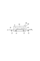
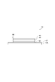
- An organic electronic device manufacturing method is an organic electronic device manufacturing method having an organic functional layer, and includes a substrate drying step of heating and drying a plastic substrate containing moisture, and a substrate drying step.
- the plastic substrate is heated by infrared rays by irradiating the plastic substrate with infrared rays.
- the integrated value in the first wavelength range of 1.2 ⁇ m to 5.0 ⁇ m is larger than the integrated value of the second wavelength range of 5.0 ⁇ m to 10.0 ⁇ m.
- the absorption spectrum of water contained in the plastic substrate has a peak at 2.9 ⁇ m included in the first wavelength range.
- the plastic material constituting the plastic substrate has little absorption in the first wavelength range and tends to have large absorption in the second wavelength range. Accordingly, by irradiating infrared light having a larger spectral component (or energy) in the first wavelength range than in the second wavelength range, moisture in the substrate is directly heated by infrared light in the first wavelength range, and the second wavelength range. It is possible to indirectly heat the moisture by the temperature rise of the plastic substrate due to the absorption of infrared rays and the accompanying heat transfer. That is, in the above method, moisture can be directly heated by infrared rays and indirectly heated. Due to these two effects, moisture can be heated and evaporated in a shorter time than before. As a result, the substrate can be dried by effectively heating and evaporating moisture while suppressing the temperature of the plastic substrate to, for example, the glass transition temperature or lower.
- the plastic substrate is dried in this way, an element body is formed on the plastic substrate to manufacture an organic electronic element. Since the plastic substrate can be dried in a shorter time than before and the plastic substrate can be dried without causing damage such as thermal deformation of the plastic substrate, the productivity of the organic electronic device can be improved.
- the substrate drying method includes a substrate drying process in which a plastic substrate containing moisture is irradiated with infrared rays and heated to dry, and has a first wavelength range of 1.2 ⁇ m to 1 in the infrared emission spectrum.
- the integrated value of 5.0 ⁇ m is larger than the integrated value of the second wavelength range of 5.0 ⁇ m to 10.0 ⁇ m.
- the absorption spectrum of water contained in the plastic substrate has a peak at 2.9 ⁇ m included in the first wavelength range.
- the plastic material constituting the plastic substrate has little absorption in the first wavelength range and tends to have large absorption in the second wavelength range. Accordingly, by irradiating infrared light having a larger spectral component in the first wavelength range than in the second wavelength range, moisture in the substrate is directly heated by infrared light in the first wavelength range, and by absorption of infrared light in the second wavelength range. It is possible to indirectly heat the moisture by the temperature rise of the plastic substrate and the accompanying heat transfer. That is, in the above method, moisture can be directly heated by infrared rays and indirectly heated. Due to these two effects, moisture can be heated and evaporated in a shorter time than before. As a result, the substrate can be dried by effectively heating and evaporating moisture while suppressing the temperature of the plastic substrate to, for example, the glass transition temperature or lower.
- the integrated value in the first wavelength range may be smaller than the integrated value in the second wavelength range.
- absorption of infrared rays in the first wavelength range can be further suppressed by the plastic material with respect to infrared rays whose integrated value in the first wavelength range is larger than that in the second wavelength range in the radiation spectrum. Therefore, it is possible to suppress an excessive temperature rise of the substrate while indirectly heating the moisture in the plastic substrate by infrared absorption in the second wavelength range.
- the integrated value of the first wavelength range is A1
- A1 / (A1 + A2) may be 0.2 or more.
- the plastic substrate in the substrate drying step, may be heated by a heat source different from infrared rays, in addition to heating by infrared rays.
- the plastic substrate is also heated by the heat source as well as heating by infrared rays, when the plastic substrate is heated, moisture in the plastic substrate can be more efficiently removed.
- the plastic substrate in the substrate drying step, is heated so that the temperature of the plastic substrate is equal to or lower than the glass transition temperature of the plastic material constituting the plastic substrate. Is preferred. Thereby, deformation of the plastic substrate can be prevented.
- the moisture content of the plastic substrate after the substrate drying step is 100 ppm or less. Thereby, deterioration of an organic electronic element can be prevented.
- a barrier layer may be formed on the surface of the plastic substrate on the side where the device body is formed. Thereby, moisture hardly penetrates into the element body.
- the plastic substrate has flexibility
- the substrate drying step is a plastic substrate continuously fed from the plastic substrate wound on the unwinding roll. May be performed during the process of winding the film on a winding roll.
- the substrate drying process is performed by a so-called roll-to-roll method.
- the organic electronic device may be an organic electroluminescence device, an organic photoelectric conversion device, or an organic thin film transistor.
- an organic electronic device manufacturing method and a substrate drying method capable of drying a substrate in a shorter time while suppressing damage to the substrate in the substrate drying step.
- FIG. 1 is a drawing schematically showing an example of the configuration of an organic EL element which is an embodiment of an organic electronic element according to the present invention.
- FIG. 2 is a schematic diagram for explaining an absorption spectrum of a plastic material constituting the substrate.
- FIG. 3 is a schematic view of a method for producing an organic EL element by a roll-to-roll method.
- FIG. 4 is a schematic diagram illustrating an example of a substrate drying process.
- FIG. 5 is a drawing showing an example of the product spectrum of the infrared radiation spectrum and the absorption spectrum of the plastic material constituting the plastic substrate.
- FIG. 6 is a schematic diagram illustrating an example of a hole transport layer forming step.
- FIG. 7 is a schematic diagram for explaining the absorption spectrum of the coating film.
- FIG. 1 is a drawing schematically showing an example of the configuration of an organic EL element which is an embodiment of an organic electronic element according to the present invention.
- FIG. 2 is a schematic diagram for explaining an absorption spectrum of
- FIG. 8 is a drawing showing an example of a product spectrum of an infrared radiation spectrum and an absorption spectrum of a coating film serving as a hole transport layer.
- FIG. 9 is a schematic diagram showing an example of the hole injection layer forming step.
- FIG. 10 is a drawing showing an example of a product spectrum of an infrared radiation spectrum and an absorption spectrum of a coating film for a hole injection layer.
- FIG. 11 is a graph showing changes in the crosslinking rate with respect to the infrared irradiation time.
- FIG. 12 is a drawing schematically showing an example of the configuration of an organic photoelectric conversion element which is an embodiment of the organic electronic element according to the present invention.
- FIG. 13 is a drawing schematically showing an example of the configuration of an organic transistor which is an embodiment of an organic electronic device according to the present invention.
- FIG. 14 is a drawing for explaining an evaluation method in an evaluation experiment of substrate deformation due to heat, (a) shows a test piece before heat treatment, and (b) shows a test piece after heat treatment. Is shown.
- the organic electronic device is an organic electroluminescence device (hereinafter referred to as an organic EL device) 1A schematically shown in FIG.
- the organic EL element 1A can be suitably used for a curved or flat illumination device, for example, a planar light source used as a light source of a scanner, and a display device.
- the organic EL element 1A includes a substrate 10 and an anode layer 21, a hole injection layer 22, a hole transport layer 23, a light emitting layer 24, an electron injection layer 25, A cathode layer 26.
- a laminate including the anode layer 21, the hole injection layer 22, the hole transport layer 23, the light emitting layer 24, the electron injection layer 25, and the cathode layer 26 is also referred to as an element body 20.
- the hole injection layer 22, the hole transport layer 23, and the light emitting layer 24 disposed between the anode layer 21 and the cathode layer 26, which are two electrodes, are organic thin films containing an organic material, each having a predetermined function. It is a functional layer (hereinafter also referred to as an organic functional layer).
- the electron injection layer 25 is also a thin film and is a functional layer having a predetermined function.
- the electron injection layer 25 may also be an organic functional layer containing an organic material.
- the organic functional layer is usually sealed with a sealing member (for example, glass) because the organic functional layer is deteriorated by moisture.
- the organic EL element 1A may be a bottom emission type, that is, a configuration in which light emitted from the light emitting layer 24 is emitted through the substrate 10 in the configuration shown in FIG. 1, or a top emission type, that is, as shown in FIG. In the configuration, the light emitted from the light emitting layer 24 may be emitted through the substrate 10.
- the organic EL element 1A is a bottom emission type.
- the substrate 10 is a plastic substrate, and is made of a plastic material that substantially transmits visible light emitted from the light emitting layer 24 (for example, light having a wavelength of 360 nm to 830 nm).
- the substrate 10 is preferably colorless and transparent with respect to the light emitted from the light emitting layer 24.
- plastic material constituting the substrate 10 examples include polyethersulfone (PES); polyester resin such as polyethylene terephthalate (PET) and polyethylene naphthalate (PEN); polyolefin such as polyethylene (PE), polypropylene (PP), and cyclic polyolefin Resin; Polyamide resin; Polycarbonate resin; Polystyrene resin; Polyvinyl alcohol resin; Saponified ethylene-vinyl acetate copolymer; Polyacrylonitrile resin; Acetal resin; Polyimide resin;
- a polyester resin or a polyolefin resin is preferable, and polyethylene terephthalate or polyethylene naphthalate is particularly preferable because of high heat resistance, low coefficient of linear expansion, and low manufacturing cost.
- These resins may be used alone or in combination of two or more.
- the main component of the substrate 10, that is, the plastic material generally has a first wavelength range of 1.2 ⁇ m to 5.0 ⁇ m (hereinafter simply referred to as “first” in the absorption spectrum AS 1 of the plastic material.
- the integrated value (the area of the hatched portion of the first wavelength range in FIG. 2) in the second wavelength range is 5.0 ⁇ m to 10 ⁇ m (hereinafter also simply referred to as “second wavelength range”).
- the absorption characteristic is smaller than the value (the area of the hatched portion in the second wavelength range in FIG. 2). That is, plastic materials typically tend to have more absorption for infrared radiation in the second wavelength range.
- the horizontal axis represents wavelength ( ⁇ m), and the vertical axis represents absorbance.
- FIG. 2 is a conceptual diagram for explaining the absorption characteristics of the plastic material in one embodiment, and the peak position, the magnitude of absorbance, and the like are schematically shown. Therefore, the absorbance on the vertical axis is an arbitrary unit.
- the thickness of the substrate 10 is not particularly limited, but is, for example, 10 ⁇ m or more and 1 mm or less.
- the substrate 10 may be in the form of a film.
- the organic EL element 1A having flexibility as a whole can be manufactured in a roll-to-roll manner.
- An electrode and a drive circuit for driving the organic EL element 1A may be formed in advance on the substrate 10.
- the moisture content of the substrate 10 is, for example, 100 ppm or less.
- a barrier layer 27 that is a barrier film may be provided on the surface of the substrate 10.
- the barrier layer 27 is a layer for reducing the influence on the element body 20 if the substrate 10 contains moisture.
- Examples of the material of the barrier layer 27 are, for example, silicon oxide, silicon nitride, silicon oxynitride, and the like.
- the barrier layer 27 may have a structure in which these films are stacked, or may have a structure in which the composition in the film is repeatedly changed in the film thickness direction.
- An example of the thickness of the barrier layer 27 is not less than 100 nm and not more than 10 ⁇ m.
- an electrode layer exhibiting optical transparency is used.
- a thin film of metal oxide, metal sulfide, metal or the like having high electrical conductivity can be used, and a thin film having high light transmittance is preferably used.
- a thin film made of, for example, indium oxide, zinc oxide, tin oxide, ITO, indium zinc oxide (abbreviated as IZO), gold, platinum, silver, copper, or the like is used.
- a thin film made of ITO, IZO or tin oxide is preferably used.
- an organic transparent conductive film such as polyaniline or a derivative thereof, polythiophene or a derivative thereof may be used.
- the thickness of the anode layer 21 can be appropriately determined in consideration of light transmittance, electrical conductivity, and the like.
- the thickness of the anode layer 21 is, for example, 10 nm to 10 ⁇ m, preferably 20 nm to 1 ⁇ m, and more preferably 50 nm to 500 nm.
- Examples of the method for forming the anode layer 21 include a vacuum deposition method, a sputtering method, an ion plating method, a plating method, and a coating method.
- the hole injection layer 22 is a layer having a function of improving the hole injection efficiency from the anode layer 21.
- the hole injection material constituting the hole injection layer 22 is classified into a low molecular compound and a high molecular compound.
- the hole injection material may have a crosslinkable group.
- low-molecular compound examples include metal oxides such as vanadium oxide, molybdenum oxide, ruthenium oxide, and aluminum oxide, metal phthalocyanine compounds such as copper phthalocyanine, and carbon.
- polymer compound examples include polyaniline, polythiophene, polythiophene derivatives such as polyethylenedioxythiophene (PEDOT), polypyrrole, polyphenylene vinylene, polythienylene vinylene, polyquinoline and polyquinoxaline, and derivatives thereof; aromatic amine structure Conductive polymers such as polymers containing in the main chain or side chain.
- PEDOT polyethylenedioxythiophene
- Ppyrrole polypyrrole
- polyphenylene vinylene polythienylene vinylene
- polyquinoline and polyquinoxaline and derivatives thereof
- Conductive polymers such as polymers containing in the main chain or side chain.
- the electrical conductivity of the conductive polymer is preferably 1 ⁇ 10 ⁇ 5 S / cm to 1 ⁇ 10 3 S / cm.
- the conductive polymer may be doped with an appropriate amount of ions.
- the kind of ions to be doped is an anion, and examples of the anion include polystyrene sulfonate ion, alkylbenzene sulfonate ion and camphor sulfonate ion. Doping ions may be used alone or in combination of two or more.
- a conventionally known organic material having a hole transporting property can be used as a hole injecting material by combining this with an electron accepting material.
- a heteropoly acid compound or an aryl sulfonic acid can be suitably used as the electron-accepting material.
- the heteropoly acid compound has a structure in which a hetero atom is located at the center of a molecule, which is represented by a chemical structure of Keggin type or Dawson type, and is an oxygen acid such as vanadium (V), molybdenum (Mo), tungsten (W), etc.
- This is a polyacid obtained by condensing an isopolyacid and an oxygen acid of a different element.
- the oxygen acid of a different element mainly include silicon (Si), phosphorus (P), and arsenic (As) oxygen acids.
- Specific examples of the heteropolyacid compound include phosphomolybdic acid, silicomolybdic acid, phosphotungstic acid, phosphotungstomolybdic acid, and silicotungstic acid.
- Aryl sulfonic acids include benzene sulfonic acid, tosylic acid, p-styrene sulfone, 2-naphthalene sulfonic acid, 4-hydroxybenzene sulfonic acid, 5-sulfosalicylic acid, p-dodecyl benzene sulfonic acid, dihexyl benzene sulfonic acid, 2,5 -Dihexylbenzenesulfonic acid, dibutylnaphthalenesulfonic acid, 6,7-dibutyl-2-naphthalenesulfonic acid, dodecylnaphthalenesulfonic acid, 3-dodecyl-2-naphthalenesulfonic acid, hexylnaphthalenesulfonic acid, 4-hexyl-1-naphthalene Sulfonic acid, octylnaphthalenesulfonic acid,
- a heteropoly acid compound and an aryl sulfonic acid may be mixed and used.
- the thickness of the hole injection layer 22 varies depending on the material used, and is determined as appropriate in consideration of the required characteristics and the ease of film formation.
- the thickness of the hole injection layer 22 is, for example, 1 nm to 1 ⁇ m, preferably 2 nm to 500 nm, more preferably 5 nm to 200 nm.
- the hole injection layer is formed by, for example, a coating method.
- the hole injection layer 22 may be formed by a predetermined known method different from the coating method.
- activation by heat may be necessary after drying the coating film containing the hole injection material.
- the activation means that an electron accepting function that the hole injection layer should have is expressed.
- the hole transport layer 23 has a function of receiving holes from the hole injection layer 22 (or the anode layer 21 when there is no hole injection layer 22) and transporting holes to the light emitting layer 24.
- the hole transport layer 23 includes a hole transport material.
- the hole transport material is not particularly limited as long as it is an organic compound having a hole transport function.
- Specific examples of the organic compound having a hole transport function include polyvinyl carbazole or a derivative thereof, polysilane or a derivative thereof, a polysiloxane derivative having an aromatic amine residue in a side chain or a main chain, a pyrazoline derivative, an arylamine derivative, a stilbene Derivative, triphenyldiamine derivative, polyaniline or derivative thereof, polythiophene or derivative thereof, polypyrrole or derivative thereof, polyarylamine or derivative thereof, poly (p-phenylene vinylene) or derivative thereof, polyfluorene derivative, aromatic amine residue And a polymer compound having poly (2,5-thienylene vinylene) or a derivative thereof.
- the organic compound having a hole transport function is preferably a polymer compound such as a polymer. This is because when the organic compound having a hole transport function is a polymer compound, the film formability is improved, and the light emitting property of the organic EL element 1A can be made uniform.
- the number average molecular weight in terms of polystyrene of the organic compound having a hole transport function is, for example, 10,000 or more, preferably 3.0 ⁇ 10 4 to 5.0 ⁇ 10 5 , more preferably 6.0 ⁇ 10 4. ⁇ 1.2 ⁇ 10 5 .
- the weight average molecular weight in terms of polystyrene of the organic compound having a hole transport function is, for example, 1.0 ⁇ 10 4 or more, preferably 5.0 ⁇ 10 4 to 1.0 ⁇ 10 6 , more preferably 1 0.0 ⁇ 10 5 to 6.0 ⁇ 10 5 .
- organic compounds having a hole transport function include polyvinyl carbazole or a derivative thereof, polysilane or a derivative thereof, a polysiloxane derivative having an aromatic amine residue in a side chain or a main chain, polyaniline or a derivative thereof, polythiophene Or a derivative thereof, a polyfluorene derivative, a polymer compound having an aromatic amine residue, poly (p-phenylene vinylene) or a derivative thereof, and a polymer hole such as poly (2,5-thienylene vinylene) or a derivative thereof Transport materials are preferred, more preferably polyvinyl carbazole or derivatives thereof, polysilane or derivatives thereof, polysiloxane derivatives having aromatic amine residues in the side chain or main chain, polyfluorene derivatives, and polymerisation having aromatic amine residues Thing is.
- the organic compound having a hole transport function is a low molecule, it is preferably used by being dispersed in a polymer binder.
- Polyvinylcarbazole or a derivative thereof, which is an organic compound having a hole transport function can be obtained, for example, by cationic polymerization of a vinyl monomer or radical polymerization.
- polysilanes or derivatives thereof which are organic compounds having a hole transporting function
- examples of polysilanes or derivatives thereof, which are organic compounds having a hole transporting function include compounds described in Chem. Rev. 89, 1359 (1989), GB GB2300196 published specification. Etc.
- the synthesis method methods described in these documents can be used, and the Kipping method is particularly preferably used.
- polysiloxane or a derivative thereof a compound having the structure of the low molecular hole transport material in the side chain or main chain is preferably used because the siloxane skeleton structure has almost no hole transport property.
- examples of the polysiloxane or derivatives thereof include compounds having a hole transporting aromatic amine residue in the side chain or main chain.
- R 1 and R 2 may be the same or different and each independently represents a hydrogen atom, an alkyl group, an alkoxy group, an aryl group, or a monovalent heterocyclic group.
- alkyl group include groups having 1 to 10 carbon atoms.
- alkoxy group include groups having 1 to 10 carbon atoms.
- Examples of the aryl group include a phenyl group and a naphthyl group.
- Examples of monovalent heterocyclic groups include pyridyl groups.
- the aryl group and the monovalent heterocyclic group may have a substituent.
- Examples of the substituent include an alkyl group having 1 to 10 carbon atoms and a carbon atom from the viewpoint of improving the solubility of the polymer compound. Examples thereof include an alkoxy group having 1 to 10 atoms.
- the substituent of the aryl group and monovalent heterocyclic group may have a crosslinkable group.
- crosslinkable groups are vinyl, ethynyl, butenyl, acryloyl, acryloyloxyalkyl, acryloylamide, methacryloyl, methacryloyloxyalkyl, methacryloylamide, vinyl ether, vinylamino, silanol , A group having a small ring (for example, cyclopropane, cyclobutane, epoxide, oxetane, diketene, episulfide, etc.) (for example, cyclopropyl group, cyclobutyl group, epoxy group, oxetane group, diketene group, episulfide group, three-membered ring or 4 Membered lactone groups, and 3-membered or 4-membered lactam groups).
- a particularly preferable organic compound having a hole transport function is a polymer containing the fluorenediyl group and the structure of an aromatic tertiary amine compound as repeating units, for example, a polyarylamine polymer.
- Examples of the repeating unit including the structure of the aromatic tertiary amine compound include a repeating unit represented by the following formula (2).
- Ar 1 , Ar 2 , Ar 3 and Ar 4 each independently represent an arylene group or a divalent heterocyclic group.
- Ar 5 , Ar 6 and Ar 7 each independently represents an aryl group or a monovalent heterocyclic group.
- Ar 6 and Ar 7 may be combined to form a ring together with the nitrogen atom to which Ar 6 and Ar 7 are bonded.
- m and n each independently represents 0 or 1.
- arylene groups include phenylene groups.
- divalent heterocyclic group include a pyridinediyl group. These groups may have a substituent.
- Examples of the aryl group include a phenyl group and a naphthyl group.
- Examples of the monovalent heterocyclic group include a pyridyl group. These groups may have a substituent.
- Examples of monovalent heterocyclic groups include thienyl group, furyl group, pyridyl group and the like.
- the substituent that the arylene group, aryl group, divalent heterocyclic group and monovalent heterocyclic group may have, from the viewpoint of the solubility of the polymer compound, an alkyl group, an alkoxy group, an aryl group Are preferable, and an alkyl group is more preferable.
- the alkyl group include groups having 1 to 10 carbon atoms.
- the alkoxy group include groups having 1 to 10 carbon atoms.
- the aryl group include a phenyl group and a naphthyl group.
- the substituent may have a crosslinkable group.
- crosslinkable groups are vinyl, ethynyl, butenyl, acryloyl, acryloyloxyalkyl, acryloylamide, methacryloyl, methacryloyloxyalkyl, methacryloylamide, vinyl ether, vinylamino, silanol , A group having a small ring (for example, cyclopropane, cyclobutane, epoxide, oxetane, diketene, episulfide, etc.) (for example, cyclopropyl group, cyclobutyl group, epoxy group, oxetane group, diketene group, episulfide group, three-membered ring or 4 Membered lactone groups, and 3-membered or 4-membered lactam groups).
- Ar 1 , Ar 2 , Ar 3 and Ar 4 are preferably arylene groups, and more preferably phenylene groups.
- Ar 5 , Ar 6 and Ar 7 are preferably aryl groups, and more preferably phenyl groups.
- the carbon atom in Ar 2 and the carbon atom in Ar 3 are directly bonded, or bonded through a divalent group such as a group represented by —O— or a group represented by —S—. It may be.
- m and n are preferably 0.
- repeating unit represented by the formula (2) examples include a repeating unit represented by the following formula.
- a crosslinker is further used as a material having a crosslinkable group.
- crosslinking agent examples include vinyl group, ethynyl group, butenyl group, acryloyl group, acryloyloxyalkyl group, acryloylamide group, methacryloyl group, methacryloyloxyalkyl group, methacryloylamide group, vinyl ether group, vinylamino group, silanol group, Polymerizable from the group consisting of a cyclopropyl group, a cyclobutyl group, an epoxy group, an oxetane group, a diketene group, an episulfide group, a 3-membered or 4-membered lactone group, and a 3-membered or 4-membered lactam group And compounds having a group.
- a polyfunctional acrylate is preferable, and examples thereof include dipentaerythritol hexaacrylate (DPHA) and trispentaerythritol octaacrylate (TPEA).
- DPHA dipentaerythritol hexaacrylate
- TPEA trispentaerythritol octaacrylate
- the solvent used for film formation using a solution is not particularly limited as long as it can dissolve a hole transport material.
- the solvent include chloride solvents such as chloroform, methylene chloride and dichloroethane, ether solvents such as tetrahydrofuran, aromatic hydrocarbon solvents such as toluene and xylene, ketone solvents such as acetone and methyl ethyl ketone, ethyl acetate, butyl acetate and ethyl.
- Examples include ester solvents such as cellosolve acetate.
- An example of a film forming method using a solution is a coating method.
- the polymer binder used in the mixed solution a binder that does not excessively inhibit charge transport is preferable, and a binder that absorbs less visible light is preferably used.
- the polymer binder include polycarbonate, polyacrylate, polymethyl acrylate, polymethyl methacrylate, polystyrene, polyvinyl chloride, polysiloxane and the like.
- the thickness of the hole transport layer 23 may be selected so that the optimum value varies depending on the material used, and the drive voltage and the light emission efficiency are appropriate values.
- the hole transport layer 23 needs to have a thickness that does not generate pinholes. If the hole transport layer 23 is too thick, the driving voltage of the organic EL element 1A may be increased.
- the thickness of the hole transport layer 23 is, for example, 1 nm to 1 ⁇ m, preferably 2 nm to 500 nm, and more preferably 5 nm to 200 nm.
- the light emitting layer 24 usually includes an organic material that mainly emits at least one of fluorescence and phosphorescence, or an organic material and a light emitting layer dopant material that assists the organic material.
- the dopant material for the light emitting layer is added, for example, in order to improve the light emission efficiency or change the light emission wavelength.
- the organic substance is preferably a polymer compound from the viewpoint of solubility.
- the light emitting layer 24 preferably includes a polymer compound having a polystyrene-equivalent number average molecular weight of 10 3 to 10 8 .
- Examples of the light-emitting material constituting the light-emitting layer 24 include organic substances that mainly emit at least one of fluorescence and phosphorescence, such as the following dye materials, metal complex materials, and polymer materials, and dopant materials for the light-emitting layer. Can do.
- coloring materials include cyclopentamine derivatives, tetraphenylbutadiene derivatives, triphenylamine derivatives, oxadiazole derivatives, pyrazoloquinoline derivatives, distyrylbenzene derivatives, distyrylarylene derivatives, pyrrole derivatives, thiophene ring compounds, pyridine rings.
- coloring materials include compounds, perinone derivatives, perylene derivatives, oligothiophene derivatives, oxadiazole dimers, pyrazoline dimers, quinacridone derivatives, and coumarin derivatives.
- Metal complex materials examples include rare earth metals such as Tb, Eu, and Dy, or Al, Zn, Be, Pt, Ir, and the like as a central metal, and an oxadiazole, thiadiazole, phenylpyridine, phenylbenzimidazole, and quinoline structure. And a metal complex having such as a ligand.
- metal complexes include metal complexes having light emission from triplet excited states such as iridium complexes and platinum complexes, aluminum quinolinol complexes, benzoquinolinol beryllium complexes, benzoxazolyl zinc complexes, benzothiazole zinc complexes, azomethyl zinc complexes, Porphyrin zinc complex, phenanthroline europium complex, etc. are mentioned.
- polymer material examples include a polyparaphenylene vinylene derivative, a polythiophene derivative, a polyparaphenylene derivative, a polysilane derivative, a polyacetylene derivative, a polyfluorene derivative, a polyvinylcarbazole derivative, a material obtained by polymerizing the above-described dye material and metal complex material, and the like. Can be mentioned.
- Dopant material for light emitting layer examples include perylene derivatives, coumarin derivatives, rubrene derivatives, quinacridone derivatives, squalium derivatives, porphyrin derivatives, styryl dyes, tetracene derivatives, pyrazolone derivatives, decacyclene, and phenoxazone.
- the thickness of the light emitting layer 24 is usually about 2 nm to 200 nm.
- the light emitting layer 24 is formed by, for example, a coating method using a coating liquid (for example, ink) containing the above light emitting material.
- the solvent of the coating liquid containing the light emitting material is not particularly limited as long as it dissolves the light emitting material, and examples thereof include a solvent of the coating liquid for forming the hole transport layer 23.
- the electron injection layer 25 has a function of improving the electron injection efficiency from the cathode layer 26.
- the material constituting the electron injection layer 25 is appropriately selected according to the type of the light emitting layer 24. Examples of the material constituting the electron injection layer 25 include alkali metals, alkaline earth metals, alloys containing one or more of alkali metals and alkaline earth metals, oxides of alkali metals or alkaline earth metals, halogens Compound, carbonate, or a mixture of these substances.
- alkali metals, alkali metal oxides, halides, and carbonates include lithium, sodium, potassium, rubidium, cesium, lithium oxide, lithium fluoride, sodium oxide, sodium fluoride, potassium oxide, potassium fluoride , Rubidium oxide, rubidium fluoride, cesium oxide, cesium fluoride, lithium carbonate and the like.
- alkaline earth metals, alkaline earth metal oxides, halides and carbonates include magnesium, calcium, barium, strontium, magnesium oxide, magnesium fluoride, calcium oxide, calcium fluoride, barium oxide, Examples include barium fluoride, strontium oxide, strontium fluoride, and magnesium carbonate.
- a layer in which a conventionally known electron transporting organic material and an alkali metal organometallic complex are mixed can be used as the electron injection layer.
- electron transporting materials include, for example, compounds having condensed aryl rings such as naphthalene and anthracene and derivatives thereof, styryl aromatic ring derivatives represented by 4,4-bis (diphenylethenyl) biphenyl, Perylene derivatives, perinone derivatives, coumarin derivatives, naphthalimide derivatives, anthraquinone, naphthoquinone, diphenoquinone, anthraquinodimethane, tetracyanoanthraquinodimethane, and other quinone derivatives, phosphate derivatives, carbazole derivatives, indole derivatives, tris (8 -Quinolinolates), quinolinol complexes such as aluminum (III), and hydroxyazole complexes such as hydroxyphenyloxazole complexes, azomethine complexes, tropolone metal complexes and flavonol metal complexes, electron acceptance And compounds having a heteroaryl rings
- the electron-accepting nitrogen represents a nitrogen atom that forms a multiple bond with an adjacent atom. Since the nitrogen atom has a high electronegativity, the multiple bond also has an electron-accepting property. Therefore, a heteroaryl ring having an electron-accepting nitrogen has a high electron affinity.
- these compounds having a heteroaryl ring structure having an electron-accepting nitrogen include benzimidazole derivatives, benzthiazole derivatives, oxadiazole derivatives, thiadiazole derivatives, triazole derivatives, pyridine derivatives, pyrazine derivatives, phenanthroline derivatives, quinoxaline.
- Preferred examples include derivatives, quinoline derivatives, benzoquinoline derivatives, oligopyridine derivatives such as bipyridine and terpyridine, quinoxaline derivatives, naphthyridine derivatives, and phenanthroline derivatives.
- organometallic complexes of alkali metals include 8-quinolinol lithium, 8-quinolinol sodium, 8-quinolinol potassium, 8-quinolinol rubidium, 8-quinolinol cesium, benzo-8-quinolinol.
- an ionic polymer compound containing an alkali metal salt in the side chain described in International Publication No. 12/133229 is also used as the electron injection layer.
- the electron injection layer 25 may be composed of a laminate in which two or more layers are laminated, for example, LiF / Ca.
- the electron injection layer 25 can be formed by a predetermined known method such as a vapor deposition method, a sputtering method, or a printing method.
- the thickness of the electron injection layer 25 is preferably about 1 nm to 1 ⁇ m.
- the material of the cathode layer 26 is preferably a material having a small work function, easy electron injection into the light emitting layer 24, and high electrical conductivity.
- the material of the cathode layer 26 is preferably a material having a high visible light reflectance.
- Examples of the material of the cathode layer 26 include alkali metals, alkaline earth metals, transition metals, and Group 13 metals of the periodic table.
- Examples of the material of the cathode layer 26 include lithium, sodium, potassium, rubidium, cesium, beryllium, magnesium, calcium, strontium, barium, aluminum, scandium, vanadium, zinc, yttrium, indium, cerium, samarium, europium, terbium, ytterbium.
- a metal such as two or more alloys of the metals, one or more of the metals, and one or more of gold, silver, platinum, copper, manganese, titanium, cobalt, nickel, tungsten, tin Or an alloy thereof, graphite, or a graphite intercalation compound.
- the alloy include magnesium-silver alloy, magnesium-indium alloy, magnesium-aluminum alloy, indium-silver alloy, lithium-aluminum alloy, lithium-magnesium alloy, lithium-indium alloy, calcium-aluminum alloy, and the like.
- a transparent conductive electrode made of a conductive metal oxide, a conductive organic substance, or the like can be used as the cathode layer 26 .
- the cathode layer 26 may be composed of a laminate in which two or more layers are laminated. An electron injection layer may be used as the cathode layer 26 in some cases.
- the thickness of the cathode layer 26 is appropriately set in consideration of electric conductivity and durability.
- the thickness of the cathode layer 26 is, for example, 10 nm to 10 ⁇ m, preferably 20 nm to 1 ⁇ m, and more preferably 50 nm to 500 nm.
- Examples of the method for forming the cathode layer 26 include a vacuum deposition method, a sputtering method, a lamination method in which a metal thin film is thermocompression bonded, and a coating method.
- the substrate 10 is heated and dried (substrate drying step S10). Thereafter, the element body 20 is formed on the dried substrate 10 (element body forming step S20).
- element body forming step S20 a step of forming the anode layer 21 on the dried substrate 10 (anode layer forming step S21), a step of forming the hole injection layer 22 on the anode layer 21 (hole injection layer forming step S22).
- a step of forming the hole transport layer 23 on the hole injection layer 22 (hole transport layer forming step S23), a step of forming the light emitting layer 24 on the hole transport layer 23 (light emitting layer forming step S24), and light emission.
- each layer can be formed by the formation method exemplified in the description of each layer.
- the sealing step may be performed after the cathode layer forming step S26.
- a roll-to-roll method can be adopted as conceptually shown in FIG.
- the long flexible substrate 10 stretched between the unwinding roll 30A and the winding roll 30B is continuously transported by the transport roller 31.
- drying of the substrate 10 and each layer constituting the element body 20 may be formed in order from the substrate 10 side.
- an unwinding roll and a winding roll may be installed before and after each of the steps constituting the substrate drying step S10 and the element body forming step S20, and each step may be performed by a roll-to-roll method.
- the flexible substrate 10 is cut at a predetermined portion, The remaining steps may be performed by a single wafer method to manufacture the organic EL element 1A.
- substrate drying process One embodiment of the substrate drying method in the substrate drying step S10 will be described with reference to the case where the substrate drying step S10 is performed by a roll-to-roll method as shown in FIG. In FIG. 4, the part corresponding to board
- the heat treatment apparatus 40 is an apparatus that heats the substrate 10 by irradiating infrared rays, and is provided on the conveyance path of the substrate 10 so that the substrate 10 passes through the heat treatment apparatus 40.
- the heat treatment apparatus 40 includes an infrared irradiation unit 42 disposed in the heat treatment furnace 41 so as to face the main surface of the substrate 10 (the main surface on the side where the element body 20 is formed).
- the infrared irradiation unit 42 outputs infrared rays having a wavelength range of 1.2 ⁇ m to 10.0 ⁇ m.
- the infrared ray output from the infrared irradiation unit 42 is referred to as a first infrared ray, and the radiation spectrum of the first infrared ray is referred to as a radiation spectrum RS1.
- the radiation spectrum RS1 has an integral value of the radiation spectrum RS1 in the first wavelength range of 1.2 ⁇ m to 5.0 ⁇ m (hereinafter sometimes simply referred to as “first wavelength range”).
- the radiation spectrum is larger than the integral value of the radiation spectrum RS1 at ⁇ 10.0 ⁇ m (hereinafter sometimes simply referred to as “second wavelength range”).
- the first infrared has a larger radiation energy in the first wavelength range.
- the first infrared ray preferably has 80% or more of radiant energy in the first wavelength range out of the total radiant energy in the wavelength range of 1.2 ⁇ m to 10.0 ⁇ m.
- the first infrared may have a maximum radiation intensity in the wavelength range of 1.2 ⁇ m to 10.0 ⁇ m at any wavelength in the first wavelength range.
- the configuration of the infrared irradiation unit 42 is not particularly limited as long as the first infrared ray having the radiation spectrum RS1 can be output.
- the infrared irradiation unit 42 includes, for example, a heater capable of irradiating infrared rays and a wavelength filter (for example, an infrared filter), and has a first emission spectrum RS1 using a wavelength filter among infrared rays output from the heater. You may be comprised so that infrared rays may be output.
- the heat treatment apparatus 40 may be configured such that the dew point temperature in the heat treatment furnace 41 can be adjusted.
- the heat treatment apparatus 40 may be configured to be able to adjust the atmospheric gas in the heat treatment furnace 41.
- the substrate 10 in the heat treatment apparatus 40 is irradiated with the first infrared rays from the infrared irradiation unit 42 to heat and dry the substrate 10.
- FIG. 5 is an example of the spectrum of the above product.
- the horizontal axis in FIG. 5 represents the wavelength ( ⁇ m), and the vertical axis represents the product of the first infrared radiation spectrum RS1 and the absorption spectrum of the plastic material constituting the substrate 10.
- the unit of the vertical axis is an arbitrary unit.
- the emission spectrum RS1 of the first infrared ray irradiated from the infrared irradiation unit 42 may be adjusted so that A1 / (A1 + A2) satisfies 0.2 or more.
- the first infrared radiation spectrum RS1 can be adjusted by adjusting the temperature of the heater and combining the infrared filter.
- the example of the drying time (first infrared irradiation time) of the substrate 10 is within 10 minutes.
- a heat source different from infrared rays may be used in combination.
- the heat source include hot air, heat generation of a lamp included in the infrared irradiation unit 42, and the like.
- FIG. 4 as an example, a form in which a hot air supply device 43 that supplies hot air is attached to the heat treatment furnace 41 is illustrated.
- the hot air supply device 43 is attached to the heat treatment furnace 41 so that the hot air flows in parallel with the transport direction of the substrate 10, for example, as indicated by the dashed arrows in FIG. 4.
- the distance between the infrared irradiation unit 42 and the substrate 10 are adjusted so that the temperature of the substrate 10 is equal to or lower than the glass transition temperature (Tg) of the material constituting the substrate.
- Tg glass transition temperature
- an organic functional layer forming method using infrared heating together with a coating liquid containing a material having a crosslinkable group (including a polymerizable group) A case where the hole transport layer 23 which is one of the layers is formed will be described as an example.
- FIG. 6 the case where the hole transport layer 23 is formed by a roll-to-roll method will be described.
- the part corresponding to hole transport layer formation process S23 is typically extracted and shown among the manufacturing processes of the organic EL element 1A by the roll-to-roll method conceptually shown in FIG. The illustration of the part corresponding to the process is omitted.
- FIG. 6 shows a state in which the hole transport layer 23 is formed while the anode layer 21 and the hole injection layer 22 formed at predetermined positions of the long substrate 10 are transported.
- the layer configuration on the substrate 10 is shown enlarged.
- the coating apparatus 50 and the heat treatment apparatus 60 schematically shown in FIG. 6 are used.
- the coating apparatus 50 is a coating liquid that is to be a hole transport layer 23 on the hole injection layer 22 formed on the substrate 10 through the hole injection layer formation step S22 on the transport path of the substrate 10 and is crosslinkable.
- the coating device 50 may be any device according to a coating method (a method for coating a prepared coating solution).
- Examples of coating methods that can be used in the roll-to-roll method include slit coating (die coating), micro gravure coating, gravure coating, bar coating, roll coating, wire bar coating, spray coating, and screen. Examples thereof include printing methods, flexographic printing methods, offset printing methods, inkjet printing methods, and nozzle printing methods. Examples of methods that can be used in the sheet-to-sheet method include a spin coating method and a casting method in addition to these methods.
- the coating method is an inkjet printing method
- the coating device 50 may be an inkjet device including an inkjet nozzle.
- the heat treatment device 60 is a device that heat-treats the coating film 23a made of the coating solution applied from the coating device 50 by irradiating infrared rays.
- the heat treatment apparatus 60 is provided on the conveyance path of the substrate 10 so that the substrate 10 passes through the heat treatment apparatus 40.
- the heat treatment apparatus 60 includes an infrared irradiation unit 62 disposed in the heat treatment furnace 61 so as to face the main surface of the substrate 10 (the main surface on the side where the element body 20 is formed).
- the infrared ray output from the infrared irradiation unit 62 is referred to as a second infrared ray, and the radiation spectrum of the second infrared ray is referred to as a radiation spectrum RS2.
- the second infrared ray includes an infrared ray having a wavelength range of 1.2 ⁇ m to 10.0 ⁇ m.
- the shape of the radiation spectrum RS2 may be the same as or different from the shape of the radiation spectrum RS1.
- the conditions satisfied by the radiation spectrum RS2 are as follows. That is, the radiation spectrum RS2 has a wavelength (maximum peak wavelength) corresponding to the maximum radiation intensity in the wavelength range of 1.2 ⁇ m to 10.0 ⁇ m in the first wavelength range of 1.2 ⁇ m to 5.0 ⁇ m.
- the integrated value in the first wavelength range of 1.2 ⁇ m to 5.0 ⁇ m is larger than the integrated value in the second wavelength range of 5.0 ⁇ m to 10.0 ⁇ m.
- the second infrared ray has greater radiant energy in the first wavelength range.
- the radiation spectrum RS2 has radiant energy of 80% or more of the total radiant energy in the wavelength range of 1.2 ⁇ m to 10.0 ⁇ m in the first wavelength range.
- the configuration of the infrared irradiation unit 62 is not particularly limited as long as the second infrared ray having the radiation spectrum RS2 can be output.
- a heater capable of emitting infrared rays and a wavelength filter for example, an infrared filter
- the heat treatment apparatus 60 may have the same configuration as that of the heat treatment apparatus 40 except that the infrared irradiation unit 62 emits the second infrared ray.
- the heat treatment apparatus 60 may include a heat source different from the infrared irradiation, similarly to the heat treatment apparatus 40.
- An example of such a heat source is a hot air supply device 43 similar to the case of the heat treatment apparatus 40.
- a coating liquid that is a coating liquid that is to become the hole transport layer 23 and includes a material containing a crosslinkable group is applied onto the hole injection layer 22 by the coating apparatus 50.
- 23a is formed (coating film forming step).
- the coating film 23a that has been transported into the heat treatment apparatus 60 by transport by the transport roller 31 is irradiated with the second infrared light from the infrared irradiation unit 62 to heat the coating film 23a, thereby crosslinking the crosslinkable groups.
- the hole transport layer 23 is formed (organic functional layer forming step).
- the coating liquid applied from the coating apparatus 50 is a coating liquid containing a hole transport material (an organic compound having a hole transport function) as exemplified in the description of the hole transport layer 23, and a material containing a crosslinkable group. It is a coating liquid which has.
- the crosslinkable group may be included in an organic compound having a hole transport function.
- a crosslinker may be used as a material having a crosslinkable group as described above.
- the coating film 23a has an absorption in the wavelength range of 1.2 ⁇ m to 10.0 ⁇ m, like the absorption spectrum AS2 of the coating film 23a shown in FIG.
- the first wavelength range 1.2 ⁇ m to 5.0 ⁇ m has a wavelength corresponding to the maximum absorption peak p1 (maximum absorption wavelength).
- the coating film 23a may have an absorption peak p2 in the second wavelength range of 5.0 ⁇ m to 10.0 ⁇ m.
- the integrated value (absorption amount) in the first wavelength range of 1.2 ⁇ m to 5.0 ⁇ m is B1
- the integrated value (absorption amount) in the second wavelength range of 5.0 ⁇ m to 10.0 ⁇ m is B2.
- B1 / (B1 + B2) preferably satisfies 0.6 or more.
- FIG. 8 is an example of the spectrum of the above product.
- the horizontal axis in FIG. 8 represents the wavelength ( ⁇ m)
- the vertical axis represents the product of the radiation spectrum RS2 of the second infrared ray and the absorption spectrum AS2 of the coating film 23a.
- the unit of the vertical axis is an arbitrary unit.
- Such heating is performed by adjusting the radiation spectrum RS2 of the second infrared ray irradiated from the infrared irradiation unit 62 according to the absorption characteristics of the coating film 23a so as to satisfy, for example, B1 / (B1 + B2) ⁇ 0.6. Can be realized.
- the example of the irradiation time of the second infrared ray on the coating film 23a is within 10 minutes.
- a heat source different from infrared rays may be used in combination as in the substrate drying method.
- Other examples of the heat source are the same as those in the substrate drying method, and thus the description thereof is omitted.
- the coating film 23a is heated to crosslink the crosslinkable group, the distance between the infrared irradiation unit 62 and the coating film 23a, the heating time, the infrared irradiation intensity, etc. are adjusted, and the temperature of the substrate 10 constitutes the substrate 10.
- the coating film 23a is heated so as to be equal to or lower than the glass transition temperature (Tg) of the plastic material.
- a method of forming an organic functional layer as an organic thin film using infrared heating while using a coating liquid containing a material having a crosslinkable group is exemplified by the case where the hole transport layer 23 is formed.
- this method can also be applied to the formation of organic thin films other than the hole transport layer 23 (for example, the hole injection layer 22, the light emitting layer 24, and the electron injection layer 25).
- the organic functional layer other than the hole transport layer 23 is formed using an application liquid containing a material having a crosslinkable group
- the material that is the main component of the organic functional layer to be formed A coating solution containing a material having a crosslinkable group (for example, a hole injection material, a light emitting material, or the like) may be used.
- the material itself for expressing the predetermined function of the organic functional layer does not have a crosslinkable group, and the crosslinker is used as a material having a crosslinkable group.
- the material itself for expressing the predetermined function of the organic functional layer has a crosslinkable group,
- the material itself for expressing the predetermined function of the organic functional layer is crosslinkable A form having a group and further containing a crosslinking agent is included.
- the hole injection material of the hole injection layer 22 formed using the activation treatment method is preferably a material having an electron accepting property, such as a conventionally known organic material having a hole transporting property.
- a material containing an electron-accepting material is preferable.
- FIG. 9 Activation treatment method in hole injection layer formation
- the hole injection layer 22 is formed by a roll-to-roll method
- the part corresponding to a hole injection layer formation process is typically extracted and shown among the manufacturing processes of the organic EL element 1A by the roll-to-roll system conceptually shown in FIG. Illustration of portions corresponding to other steps is omitted.
- FIG. 9 shows a state in which the hole injection layer 22 is formed while the anode layer 21 formed at a predetermined position of the long substrate 10 is transported.
- the layer configuration on the substrate 10 is shown enlarged.
- a coating device 50 In the method for forming the hole injection layer 22 as an organic thin film, a coating device 50, a drying device 70, and a heat treatment device 80 schematically shown in FIG. 9 are used.
- the coating device 50 is the same as the device shown in FIG. 6 described in the method for forming the hole transport layer 23.
- the coating device 50 used in the hole injection layer forming step S ⁇ b> 22 applies a coating solution to be the hole injection layer 22 on the anode layer 21.
- the drying device 70 is a device that dries the coating film 22 a made of the coating liquid applied from the coating device 50.
- a layer obtained by drying the coating film 22a with the drying device 70 is referred to as an inactive hole injection layer (hole injection layer coating film) 22b.
- the drying device 70 a known drying device can be used. Examples of the drying device 70 include a drying device capable of performing hot air drying, vacuum drying, electromagnetic induction drying, infrared drying, and the like.
- the heat treatment apparatus 80 is an apparatus that heats the inactive hole injection layer 22b by irradiating infrared rays.
- the hole injecting layer 22 is obtained by activating the inactive hole injecting layer 22b by the heat treatment apparatus 80.
- the heat treatment apparatus 80 is provided on the conveyance path of the substrate 10 so that the substrate 10 passes through the heat treatment apparatus 80.
- the heat treatment apparatus 80 includes an infrared irradiation unit 82 disposed in the heat treatment furnace 81 so as to face the main surface of the substrate 10 (the main surface on the side where the element body 20 is formed).
- the infrared ray output from the infrared irradiation unit 82 is referred to as a third infrared ray, and the radiation spectrum of the third infrared ray is referred to as a radiation spectrum SP3.
- the third infrared ray includes an infrared ray having a wavelength range of 1.2 ⁇ m to 10.0 ⁇ m.
- the shape of the emission spectrum SP3 may be the same shape as the emission spectra SP1 and SP2, or may be different.
- the conditions satisfied by the radiation spectrum SP3 are as follows.
- the integral value of the radiation spectrum SP3 in the first wavelength range of 1.2 ⁇ m to 5.0 ⁇ m is larger than the integral value of the radiation spectrum SP3 in the second wavelength range of 5.0 ⁇ m to 10.0 ⁇ m.
- the third infrared has a larger radiation energy in the first wavelength range.
- the third infrared ray preferably has a radiant energy of 80% or more in the first wavelength range out of the total radiant energy in the wavelength range of 1.2 ⁇ m to 10.0 ⁇ m.
- the third infrared ray may have a wavelength (maximum peak wavelength) corresponding to a maximum radiation intensity in the wavelength range of 1.2 ⁇ m to 10.0 ⁇ m in the first wavelength range of 1.2 ⁇ m to 5.0 ⁇ m. Good.
- the coating liquid containing the above-described hole injection material (a coating liquid for hole injection layer) is applied onto the anode layer 21 from the coating device 50 to form the coating film 22a. Thereafter, the coating film 22a is dried in the drying device 70 to form the inactive hole injection layer 22b (hole injection layer coating film forming step). Then, the inactive hole injection layer 22b which is the dried coating film 22a is heated and activated to form the hole injection layer 22 (heat treatment step).
- the solvent of the coating solution for forming the hole injection layer 22 is not particularly limited as long as it dissolves the hole injection material, but examples thereof include chloride solvents such as chloroform, methylene chloride, dichloroethane, tetrahydrofuran, and the like.
- chloride solvents such as chloroform, methylene chloride, dichloroethane, tetrahydrofuran, and the like.
- examples include ether solvents, aromatic hydrocarbon solvents such as toluene and xylene, ketone solvents such as acetone and methyl ethyl ketone, and ester solvents such as ethyl acetate, butyl acetate, and ethyl cellosolve acetate.
- the inactive hole injection layer 22b as the dried coating film 22a has absorption in the first wavelength range of 1.2 ⁇ m to 5.0 ⁇ m.
- the heating activation condition includes integration in the first wavelength range in the spectrum (see FIG. 10) of the product of the third infrared radiation spectrum RS3 and the absorption spectrum AS3 of the inactive hole injection layer 22b.
- the value is C1 and the integrated value in the second wavelength range is C2, it is preferable that C1 / (C1 + C2) satisfies 0.8 or more.
- FIG. 10 is an example of the spectrum of the above product.
- the horizontal axis in FIG. 10 represents the wavelength ( ⁇ m), and the vertical axis represents the product of the third infrared radiation spectrum RS3 and the absorption spectrum of the inactive hole injection layer 22b.
- the unit of the vertical axis is an arbitrary unit.
- the third infrared radiation spectrum SP3 irradiated from the infrared irradiation unit 82 may be adjusted so that C1 / (C1 + C2) satisfies 0.8 or more.
- an example of the irradiation time of the third infrared ray on the inactive hole injection layer 22b is within 10 minutes.
- a heat source other than infrared rays may be used in combination.
- Other examples of the heat source are the same as those in the substrate drying method, and thus the description thereof is omitted.
- the temperature of the substrate 10 is adjusted by adjusting the distance between the infrared irradiation part 82 and the inactive hole injection layer 22b, the heating time, the infrared irradiation intensity, and the like.
- the inactive hole injection layer 22b is heated so as to be equal to or lower than the glass transition temperature (Tg) of the plastic material constituting the substrate 10.
- the moisture content in the substrate 10 can be reduced (for example, 100 ppm or less).
- Organic thin films that are functional layers such as the hole injection layer 22, the hole transport layer 23, the light emitting layer 24, and the electron injection layer 25 constituting the organic EL element 1A are easily deteriorated by the influence of moisture. Therefore, the product life of the organic EL element 1A can be improved by reducing the moisture content of the substrate 10.
- the substrate 10 is heated using the first infrared ray having the emission spectrum RS1.
- the first infrared ray used in the substrate drying step S10 has an infrared ray with a first wavelength range of 1.2 ⁇ m to 5.0 ⁇ m.
- water has a maximum absorption peak at a wavelength of 2.9 ⁇ m within the first wavelength range. Therefore, the water in the substrate 10 can be directly heated by the first infrared rays.
- the first infrared ray has a second wavelength range
- the plastic material which is the main component of the substrate 10 has absorption in the second wavelength range as schematically shown in FIG. Therefore, the moisture in the substrate 10 is indirectly heated by heat transfer accompanying the temperature rise of the substrate 10 due to infrared absorption in the second wavelength range of the plastic material.
- the moisture in the substrate 10 can be directly heated and indirectly heated by the first infrared ray.
- the moisture can be evaporated in a shorter time than before, so that the time required for drying the substrate 10 is shortened.
- damage to the substrate 10 can be reduced and the productivity of the organic EL element 1A can be improved.
- the plastic material which is the main component of the substrate 10 tends to have a characteristic that the integrated value of the absorption spectrum AS1 in the first wavelength range is smaller than the integrated value of the absorption spectrum AS1 in the second wavelength range.
- the integrated value of the first wavelength range is larger than the integrated value of the second wavelength range. Therefore, even if the substrate 10 has absorption in the second wavelength range, the first infrared ray has more energy in the first wavelength range, and thus heats moisture while suppressing an excessive temperature rise of the substrate 10. Is possible. Therefore, damage to the substrate 10 such as deformation of the substrate 10 is less likely to occur.
- the substrate 10 in the form in which the substrate 10 is heated under the condition of A1 / (A1 + A2) ⁇ 0.2, for example, in the form in which the substrate 10 is irradiated with the first infrared ray having the radiation spectrum RS1 that satisfies the above conditions, the substrate 10
- the substrate can be dried by effectively heating and evaporating moisture while suppressing an excessive increase in temperature due to infrared absorption. Therefore, the substrate can be dried while suppressing deformation of the substrate 10.
- the dehydration time can be shortened by heating the substrate 10 other than the first infrared ray.
- the productivity of the organic EL element 1A is easily improved.
- the ability to perform the substrate drying step S10 in a short time is effective for the roll-to-roll method.
- the productivity of the organic EL element 1A can be further improved.
- the hole transport layer 23 is formed using a coating solution containing a material having a crosslinkable group and infrared heating.
- a crosslinking reaction (including a polymerization reaction) occurs at least one of light and heat. Accordingly, the second infrared ray having the maximum radiation intensity in the first wavelength range in the wavelength range of 1.2 ⁇ m to 10.0 ⁇ m, and the coating film having the maximum absorption peak p1 in the wavelength range of 1.2 ⁇ m to 10.0 ⁇ m in the first wavelength range.
- the crosslinkable group contained in the coating film 23a is cross-linked, and an insolubilized hole transport layer 23 can be formed.
- each organic functional layer is formed by, for example, a vapor phase method, it can be laminated without any problem, but it takes time to manufacture the organic EL element.
- the coating method is used, the productivity of the organic EL element can be improved as compared with the case where the vapor phase method is used.
- the previously formed layer for example, hole transport layer
- the upper layer for example, light emitting layer
- a material contained in a coating solution for forming a layer may contain a crosslinkable group to be a crosslinkable material.
- a heating method of the coating film for crosslinking the crosslinkable group heating by a hot plate is also conceivable, but in order to cause a crosslinking reaction, heating at a high temperature (for example, 180 ° C.) for a long time (for example, 60 minutes) is possible. It was necessary.
- the substrate 10 Since such a high temperature is higher than the glass transition temperature (Tg) of the plastic material which is the main component of the substrate, the substrate 10 is damaged. Alternatively, it is conceivable to cause a crosslinking reaction in a short time by using a high-intensity laser beam, but in this case, the substrate 10 is also damaged.
- Tg glass transition temperature
- the second infrared ray having the radiation spectrum SP2 having the maximum radiation intensity at any wavelength in the first wavelength range of 1.2 ⁇ m to 5.0 ⁇ m is used to make holes.
- the coating film 23a to be the transport layer 23 is heated.
- the coating film 23a has a maximum absorption peak p1 in the first wavelength range of 1.2 ⁇ m to 5.0 ⁇ m as in the absorption spectrum AS2 shown in FIG. Therefore, much of the energy of the second infrared ray is absorbed by the coating film 23a, and the coating film 23a is directly heated by the second infrared ray. Since the substrate 10 tends to have a larger absorption in the second wavelength range than in the first wavelength range, the substrate 10 undergoes a temperature rise due to the absorption of the second infrared ray. The coating film 23 a is also indirectly heated by heat transfer due to the temperature rise of the substrate 10.
- the coating film 23a is directly heated by the second infrared irradiation, and is also indirectly heated.
- the crosslinking reaction proceeds faster and the curing time of the coating film 23a is shortened. Therefore, an excessive temperature rise of the substrate 10 can be suppressed, and damage to the substrate 10 is suppressed.
- the hole transport layer 23 can be formed by crosslinking the crosslinkable group in a shorter time (for example, 10 minutes or less) while reducing damage to the substrate 10. It is. Since the formed hole transport layer 23 is insolubilized, for example, even if the light emitting layer 24 on the hole transport layer 23 is formed by a coating method, the hole transport layer 23 and the light emitting layer 24 are not mixed.
- the product life of the organic EL element 1A can be improved. Since damage (bending, etc.) to the substrate 10 is reduced, the product life of the organic EL element 1A can be improved. Since the formation time of the hole transport layer 23 can be shortened, the productivity of the organic EL 1A can be improved. Since the hole transport layer 23 can be formed in a shorter time (for example, within 10 minutes), the organic functional layer formation method described in the hole transport layer formation step S23 completes the crosslinking reaction. Therefore, it is not necessary to secure a long transport distance in order to secure the time required for this, and it is effective for the roll-to-roll method.
- the coating film 23a has the absorption peak p2 in the second wavelength range
- the second infrared ray in the second wavelength range is absorbed, so that the coating film 23a can be heated even in the second wavelength range.
- the heating efficiency of the coating film 23a is improved, crosslinking of the crosslinkable group is likely to occur, and as a result, the time for curing the coating film 23a can be shortened.
- the second infrared ray includes the second wavelength range, as described above, if the radiant energy of the second infrared ray in the second wavelength range is smaller than the radiant energy in the first wavelength range, Damage can be reduced.
- the coating film 23 a is heated to the second infrared ray while the second infrared ray is applied to the substrate 10. The influence of infrared rays can be reduced.
- the coating film 23a has the absorption peak p2 in the second wavelength range
- the coating film 23a is mainly heated with the second infrared ray in the first wavelength range, while in the second wavelength range.
- the coating film 23a can also be heated by the second infrared ray. Therefore, the heating efficiency of the coating film 23a is improved, and the coating film 23a can be cured in a shorter time. As a result, an excessive increase in the temperature of the substrate 10 is further suppressed, and the influence of the second infrared rays on the substrate 10 can be reduced.
- the ratio of the effect of direct heating of the coating film 23a by the second infrared rays is the temperature rise due to infrared absorption of the substrate 10. And the effect of heating by heat transfer associated therewith can be increased. Therefore, the cross-linking treatment can be performed in a shorter time than in the past (for example, when a hot plate is used) while suppressing damage such as thermal deformation due to an excessive temperature rise of the substrate 10.
- the coating film 23a in the hole transport layer forming step S23 When heating the coating film 23a in the hole transport layer forming step S23, when other heat sources (such as warm air) are used in combination with infrared irradiation, the coating film 23a is further heated by the heat from the other heat sources. Further, the crosslinkable group can be easily cross-linked, and as a result, the time required for the hole transport layer forming step S23 can be shortened.
- other heat sources such as warm air
- the hole transport layer 23 is described using an example of using a coating solution containing a material having a crosslinkable group and heating by irradiation with the second infrared ray.
- a coating solution containing a material having a crosslinkable group and heating by irradiation with the second infrared ray is formed.
- the same method can be applied and the same effect can be obtained.
- the inactive hole injection layer 22b as the coating film 22a subjected to the drying process is formed using the third infrared ray.
- Heat treatment or activation treatment
- the hole injection layer 22 can be formed in a short time while reducing damage to the substrate 10. This point will be described in comparison with a case where activation processing is performed using a hot plate.
- a coating film to be the hole injection layer 22 is heated using a hot plate, the coating film needs to be heated to 180 ° C.
- Such a heating method corresponds to heating to a temperature equal to or higher than the glass transition temperature of the constituent material of the substrate when the substrate is a plastic substrate. In this case, the substrate is damaged due to the temperature of the substrate.
- the inactive hole injection layer 22b which is the coating film for the hole injection layer is heated using the third infrared ray having the emission spectrum RS3. ing.
- the third infrared ray used in the hole injection layer forming step S22 has an integral value of the radiation spectrum RS3 in the first wavelength range of 1.2 ⁇ m to 5.0 ⁇ m, and an emission spectrum RS3 in the second wavelength range of 5.0 ⁇ m to 10.0 ⁇ m. It is an infrared ray larger than the integral value of.
- the inactive hole injection layer 22b has absorption in the first wavelength range. Therefore, since the third infrared ray is efficiently absorbed by the inactive hole injection layer 22b, the inactive hole injection layer 22b is directly heated. Since the substrate 10 tends to have a larger absorption in the second wavelength range than in the first wavelength range, a temperature increase occurs due to the absorption of the third infrared ray in the substrate 10.
- the inactive hole injection layer 22b is also indirectly heated by heat transfer due to the temperature rise of the substrate 10.
- the inactive hole injection layer 22b is directly heated by the third infrared irradiation and also indirectly heated.
- the time required for the activation process of the inactive hole injection layer 22b is shortened.
- the inactive hole injection layer 22b is activated and the hole injection layer 22 is activated while suppressing an excessive temperature rise of the substrate 10. It can be. Therefore, the hole injection layer 22 can be formed in a shorter time while suppressing deformation (for example, damage) of the substrate 10 and the productivity of the organic EL element 1A can be improved.
- the substrate 10 has absorption in the second wavelength range, but since the third infrared ray has low energy in the second wavelength range, it is possible to suppress an excessive temperature rise of the substrate 10 in this respect as well. It is.
- the inactive hole injection layer 22b when C1 is larger than C2, the inactive hole injection layer 22b can be more efficiently heated with the third infrared ray in the first wavelength range, so that the inactive hole injection layer 22b can be heated in a short time. An electron accepting function can be expressed. As a result, an excessive increase in the temperature of the substrate 10 is further suppressed, and the influence of the third infrared rays on the substrate 10 can be reduced.
- the ratio of the effect of direct heating of the inactive hole injection layer 22b by the third infrared ray it becomes large with respect to the temperature rise by the infrared absorption of the board
- the inactive hole injection layer 22b When heating the inactive hole injection layer 22b, together with other heat sources (such as warm air) in combination with infrared irradiation, the inactive hole injection layer 22b is further heated by the heat from the other heat sources. Further, the heating efficiency of the inactive hole injection layer 22b is improved, and as a result, the time required for the hole injection layer forming step S22 can be shortened.
- other heat sources such as warm air
- the organic functional layer formation method described in the hole transport layer formation step S ⁇ b> 23 is used, and the substrate 10 is not damaged. While reducing, the organic functional layer to be formed can be formed in a short time. Therefore, the product life of the organic EL element 1A can be improved.
- Example 1 In Experiment 1, a PEN (polyethylene naphthalate) film (grade: Q65HA) F1 manufactured by Teijin DuPont with a film thickness of 125 ⁇ m was prepared.
- PEN polyethylene naphthalate
- Q65HA polyethylene naphthalate
- the prepared PEN film F1 was set in a heat treatment apparatus including an infrared irradiation unit.
- the distance between the PEN film F1 and the infrared irradiation part was 160 mm.
- hot air having a temperature of 71 ° C. and a flow rate of 4.2 m 3 / h is supplied to make the film surface temperature 150 ° C.
- the PEN film F1 was irradiated with the 1st infrared rays from the infrared irradiation part for 5 minutes and dried.
- An infrared heater is used as the light source of the infrared irradiation unit.
- the integral value of the first wavelength range 1.2 ⁇ m to 5.0 ⁇ m in the radiation spectrum RS1 of the first infrared used for drying is 176.5 kW / (m 2 ⁇ ⁇ m), and the second wavelength range is 5.0 ⁇ m to 10 ⁇ m.
- the integrated value of 0.0 ⁇ m was 5.18 kW / (m 2 ⁇ ⁇ m).
- the integrated value in the wavelength range of 1.2 ⁇ m to 10 ⁇ m is 100
- the integrated value in the first wavelength range was 97.1
- the integrated value in the second wavelength range was 2.9.
- the spectrum of the product of the first infrared radiation spectrum RS1 and the absorption spectrum of the PEN film F1 used in Experiment 1 was as shown in FIG.
- the PEN film F1 treated in the heat treatment apparatus 40 was sealed so as not to be exposed to the atmosphere, the Karl Fischer method (KF method) was applied to measure the residual moisture concentration of the PEN film, and the degree of dehydration was evaluated.
- a Karl Fischer moisture meter (type 831) manufactured by Metrohm was used for measurement of residual moisture concentration by the KF method.
- the PEN film was divided into two sheets to measure the residual moisture concentration.
- Example 2 In Experiment 2, for comparison, a PEN film similar to Experiment 1 (hereinafter referred to as PEN film F2) was heat-treated in a vacuum apparatus at 150 ° C. for 5 hours. The residual moisture concentration was evaluated by the KF method in the same manner as in Experiment 1 for the PEN film F2 thus dried.
- PEN film F2 a PEN film similar to Experiment 1
- the synthesis method of the polymer compound 1 is as follows.
- Step 1 The monomer CM1 (3.74 g) synthesized according to the method described in JP 2010-189630 A after the inside of the reaction vessel was put under a nitrogen gas atmosphere, described in International Publication No. 2005/049546 Monomer CM2 (5.81 g) synthesized according to the method, monomer CM3 (0.594 g) synthesized according to the method described in JP-A-2008-106241, and toluene (182 ml) were added to the reaction vessel, and about 80 Heated to ° C.
- dichlorobis (tris (2-methoxyphenyl) phosphine) palladium (6.62 mg)
- a 20 wt% tetraethylammonium hydroxide aqueous solution (26.0 g) were added thereto, and the mixture was stirred under reflux for about 7.5 hours.
- Step 2 Thereafter, phenylboronic acid (91.4 mg), dichlorobis (tris (2-methoxyphenyl) phosphine) palladium (6.62 mg), and 20 wt% tetraethylammonium hydroxide aqueous solution (26.0 g) And further stirred under reflux for about 15 hours.
- Step 3 Thereafter, a solution obtained by dissolving sodium N, N-diethyldithiocarbamate trihydrate (4.17 g) in ion-exchanged water (84 ml) was added thereto, followed by stirring for 2 hours while heating to 85 ° C. did. After cooling the obtained reaction solution, it was washed twice with ion exchange water, twice with 3.0 wt% aqueous acetic acid and twice with ion exchange water, and when the obtained solution was added dropwise to methanol, precipitation occurred. It was. The obtained precipitate was dissolved in toluene and purified by passing through an alumina column and a silica gel column in this order.
- the polymer compound 1 had a polystyrene-equivalent number average molecular weight (Mn) of 5.5 ⁇ 10 4 and a polystyrene-equivalent weight average molecular weight (Mw) of 1.4 ⁇ 10 5 .
- Polymer compound 1 has a theoretical value obtained from the amount of raw materials charged, a structural unit derived from monomer CM1, a structural unit derived from monomer CM2, and a structure derived from monomer CM3.
- a unit is a copolymer composed of a molar ratio of 50: 42.5: 7.5.
- Example 3 In Experiment 3, a xylene solution in which the polymer compound 1 was dissolved in xylene was prepared. The concentration of the polymer compound 1 in this xylene solution was 0.5% by weight. Next, in the air atmosphere, the obtained xylene solution was applied to a glass substrate by a spin coating method to form a coating film for a hole transport layer having a thickness of 20 nm.
- the glass substrate with the coating film thus formed was set in a heat treatment apparatus including an infrared irradiation unit.
- the distance between the glass substrate with the coating film and the infrared irradiation part was 160 mm.
- hot air having a temperature of 71 ° C. and a flow rate of 4.2 m 3 / h is used to bring the surface temperature of the glass substrate to 150 ° C.
- the hole transport layer was obtained by irradiating the glass substrate with the second infrared ray from the infrared irradiation portion for 10 minutes from the coating film side and performing heat treatment.
- the infrared irradiator uses an infrared heater.
- the integrated value of the second infrared ray used in the heat treatment in the first wavelength range of 1.2 ⁇ m to 5.0 ⁇ m is 176.5 kW / (m 2 ⁇ ⁇ m), and the second wavelength range is 5.0 ⁇ m to 10.0 ⁇ m.
- the integrated value was 5.18 kW / (m 2 ⁇ ⁇ m).
- the integrated value in the first wavelength range was 97.1
- the integrated value in the second wavelength range was 2.9.
- the spectrum of the product of the second infrared radiation spectrum and the absorption spectrum of the coating film is as shown in FIG. In FIG.
- the thickness of the hole transport layer after the heat treatment was measured with a stylus type thickness meter P16 manufactured by Tencor. Thereafter, the surface on the hole transport layer side of the glass substrate with a hole transport layer is rinsed (washed) with a xylene solvent using a spin coating method to remove uncrosslinked (soluble) components. Next, the thickness of the hole transport layer after rinsing was again measured with a stylus type film thickness meter, P16, and the crosslinking rate was calculated according to the following formula.
- Crosslinking rate (%) ⁇ (thickness of hole transport layer after rinsing) / (thickness of hole transport layer before rinsing) ⁇ ⁇ 100
- the experiment 3 was performed when the heat treatment time was changed to 1, 2, 3, 5, and 7 minutes.
- the experimental results are as shown in FIG. As shown in FIG. 11, it is 5 minutes or longer, and the coating film can be substantially cured by heating for about 10 minutes at the latest. That is, the hole transport layer can be formed in a shorter time by using the second infrared ray.
- Experiment 4 and Experiment 5 are comparative experiments with respect to Experiment 4.
- organic EL element 2a Glass substrate / ITO layer (thickness 50 nm) / layer containing hole injection material 1 (thickness 35 nm) / layer containing polymer compound 1 (thickness 20 nm) / layer containing polymer compound 2 (thickness 75 nm) ) / NaF layer (thickness 4 nm) / Al layer (thickness 100 nm) "
- the layer containing the hole injection material 1 which is a polymer compound corresponds to a hole injection layer
- the layer containing the polymer compound 1 corresponds to a hole transport layer
- the layer containing the polymer compound 2 is a light emitting layer. It corresponds to.
- the polymer compound 2 was produced as follows. That is, polymer compound 2 was produced by mixing a luminescent organometallic complex synthesized according to the method described in International Publication No. 2009-131255 with a host material as a dopant.
- a suspension of the hole injection material 1 was applied by spin coating to a glass substrate on which an ITO film (anode layer) having a thickness of 50 nm was formed by sputtering to obtain a coating film having a thickness of 35 nm.
- the glass substrate provided with the coating film was heated at 170 ° C. for 15 minutes on a hot plate in an atmospheric pressure atmosphere to evaporate the solvent. Thereafter, the glass substrate was naturally cooled to room temperature to obtain a glass substrate on which a hole injection layer containing the hole injection material 1 was formed. The hole injection layer was formed in the air atmosphere.
- a xylene solution L in which the polymer compound 1 obtained by the above synthesis example was dissolved in xylene was prepared.
- the concentration of the polymer compound 1 in the xylene solution L was 0.5% by weight.
- the obtained xylene solution L was applied to a glass substrate by a spin coating method to form a coating film for a hole transport layer having a thickness of 20 nm.
- the glass substrate was set in a heat treatment apparatus including an infrared irradiation unit.
- the distance between the glass substrate and the infrared irradiation part was 160 mm.
- the temperature of the glass substrate is 71 ° C. and the flow rate is 4.2 m 3 / h in order to bring the surface temperature of the glass substrate to 150 ° C.
- the hole transport layer was obtained by heat-processing the glass substrate for 10 minutes with the 2nd infrared rays from an infrared irradiation part.
- the conditions of the radiation spectrum of the second infrared ray that is, the integrated values of the first wavelength range and the second wavelength range were the same as in Experiment 3.
- a xylene solution in which the polymer compound 2 as a light emitting material was dissolved in xylene was prepared.
- the concentration of the polymer compound 2 in the xylene solution was 1.3% by weight.
- the obtained xylene solution was applied to a glass substrate by a spin coating method to form a coating film for a light emitting layer having a thickness of 75 nm.
- the coating film was dried by holding at 130 ° C. for 10 minutes to obtain a light emitting layer.
- the organic EL element 2a was produced by sealing using the glass substrate which is a sealing substrate.
- the external quantum efficiency of the produced organic EL element 2a was measured. As a result, the maximum value of the external quantum efficiency was 19.4%.
- the remaining film rate was measured as follows. That is, the same xylene solution L as when the organic EL element 2a was produced was prepared. Next, in the air atmosphere, the xylene solution L was applied to a glass substrate by a spin coating method to obtain a coating film of the polymer compound 1. After heating with the heat processing apparatus 60 on the conditions similar to the case where the organic electroluminescent element 2a was produced to the obtained coating film, the xylene solvent was apply
- the same xylene solution L as that in the case of producing the organic EL element 2a was prepared.
- the xylene solution L was applied to a glass substrate by a spin coating method to obtain a coating film of the polymer compound 1.
- the thickness of the coating film not subjected to the heat treatment was measured using P16 manufactured by Tencor, a stylus type film thickness meter, and the measured value was defined as a film thickness t2.
- Experiment 5 an organic EL element was formed in the same manner as in Experiment 4 except that a hot plate was used instead of the heat treatment apparatus using the second infrared when forming the layer containing the polymer compound 1.
- the organic EL element of Experiment 5 is referred to as organic EL element 2b.
- the xylene solution L prepared in Experiment 4 was applied to a glass substrate by a spin coating method to form a coating film for a hole transport layer having a thickness of 20 nm.
- the obtained coating film is solidified by holding it at 180 ° C.
- the external quantum efficiency of the produced organic EL element 2b was measured in the same manner as in Experiment 4. As a result, the maximum value of the external quantum efficiency was 19.4%.
- the remaining film ratio was measured as follows. First, in the air atmosphere, the xylene solution L was applied to a glass substrate by a spin coating method to obtain a coating film of the polymer compound 1. After heating with a hot plate under the same conditions as when the organic EL element 2b was produced on the obtained coating film, a xylene solvent was applied to the heated coating film by spin coating, and the heated coating film was rinsed. Then, the thickness of the remaining coating film was measured using P16 manufactured by Tencor, a stylus type film thickness meter, and the measured value was defined as t3.
- the production method of the organic EL element 2c is the same as that of Experiment 4 except that the formation method of the hole injection layer is different, the formation method of the hole transport layer is different, and the formation method of the light emitting layer is different.
- a method for forming the hole injection layer, the hole transport layer, and the light emitting layer in Experiment 6 will be described.
- a suspension of the polymer compound P2 was applied by spin coating to a glass substrate on which an ITO film (anode layer) having a thickness of 50 nm was formed by sputtering to obtain a coating film having a thickness of 35 nm.
- the glass substrate provided with this coating film is dried by holding at 130 ° C. for 5 minutes using a hot plate (drying device), and then heat-treated with a heat treatment device equipped with an infrared irradiation unit to inject holes. A layer was formed.
- the glass substrate with the hole injection layer coating film dried on the hot plate was heated as follows.
- the glass substrate with the coating film for hole injection layers was set in a heat treatment apparatus.
- the distance between the glass substrate and the infrared irradiation part was 160 mm.
- hot air having a temperature of 71 ° C. and a flow rate of 4.2 m 3 / h is used to bring the surface temperature of the glass substrate to 150 ° C.
- the coating film for hole injection layer was heated (activated) for 10 minutes with the third infrared ray from the infrared irradiation section.
- the conditions of the third infrared ray from the infrared irradiation unit are the same as the conditions of the first and second infrared rays.
- the spectrum of the product of the third infrared radiation spectrum RS3 and the absorption spectrum of the coating film for hole injection layer was as shown in FIG. In FIG. 10, the integrated value C1 in the first wavelength range of 1.2 ⁇ m to 5.0 ⁇ m and the integrated value C2 in the second wavelength range of 5.0 ⁇ m to 10.0 ⁇ m are 0.538 and 0.037, respectively. , C1 / (C1 + C2) had a value of 0.953.
- a xylene solution in which the polymer compound 3 was dissolved in xylene was prepared.
- the concentration of the polymer compound 3 in this xylene solution was 0.5% by weight.
- the obtained xylene solution was applied to a glass substrate by a spin coating method to form a coating film for a hole transport layer having a thickness of 20 nm.
- the glass substrate was set in a heat treatment apparatus including an infrared irradiation unit.
- the distance between the glass substrate and the infrared irradiation part was 160 mm.
- the temperature of the glass substrate is 71 ° C. and the flow rate is 4.2 m 3 / h in order to bring the surface temperature of the glass substrate to 150 ° C.
- the hole transport layer was obtained by heat-processing the glass substrate for 10 minutes with the 2nd infrared rays from an infrared irradiation part.
- the conditions of the radiation spectrum of the second infrared ray that is, the integrated values of the first wavelength range and the second wavelength range were the same as in Experiment 3.
- a xylene solution in which the polymer compound 4 as a light emitting material was dissolved in xylene was prepared.
- the concentration of the polymer compound 4 in this xylene solution was 1.3% by weight.
- the obtained xylene solution was applied to a glass substrate by a spin coating method to form a coating film for a light emitting layer having a thickness of 75 nm.
- the coating film was dried by holding at 130 ° C. for 10 minutes to obtain a light emitting layer.
- the external quantum efficiency of the produced organic EL element 2c was measured. As a result, the maximum value of the external quantum efficiency was 16.5%.
- the driving voltage was 6.3 V at 10 mA / cm 2 .
- the element lifetime of the organic EL element 2c was measured. The element lifetime was evaluated based on LT80 expressed by the time from the start of driving until the luminance decreased to 80, assuming that the luminance at the start of driving was 100. The element lifetime was measured by starting measurement of the organic EL element 2c with an initial luminance of 3000 cd / m 2 and driving it with a constant current. As a result, the device lifetime was 155 hours.
- Experiment 7 an organic EL element was fabricated in the same manner as in Experiment 6 except that heating using a hot plate was used instead of heating using the heat treatment apparatus in Experiment 6.
- the organic EL element in Experiment 7 is referred to as organic EL element 2d.
- the heating condition on the hot plate is 230 ° C. for 15 minutes.
- the device life and external quantum efficiency were measured for the produced organic EL device 2d in the same manner as in Experiment 6. As a result, the maximum value of the external quantum efficiency was 16.5%, and the driving voltage was 6.2 V at 10 mA / cm 2 .
- the device lifetime was 160 hours.
- Experiment 8 an organic EL element was fabricated in the same manner as in Experiment 6 except that the heat treatment time was 15 minutes instead of the heat treatment time of 10 minutes in forming the hole injection layer in Experiment 6.
- the external quantum efficiency of the produced organic EL element was measured. As a result, the maximum value of the external quantum efficiency was 16.2%.
- the drive voltage was 6.3 V at 10 mA / cm 2 .
- the element lifetime of the organic EL element was measured. The element lifetime was evaluated based on LT80 expressed by the time from the start of driving until the luminance decreased to 80, assuming that the luminance at the start of driving was 100.
- the element lifetime was measured by starting measurement of the organic EL element with an initial luminance of 3000 cd / m 2 and driving it with a constant current. As a result, the device lifetime was 155 hours.
- Table 3 shows the measurement results of Experiment 6, Experiment 7, and Experiment 8.
- Experiment 6 and Experiment 8 have the effect that almost the same emission characteristics can be obtained even at a lower processing temperature and shorter processing time. You can get it regardless. Therefore, even if the polymer compound 3 is replaced with the polymer compound 1, the same effect can be confirmed. Further, even if the polymer compound 4 is replaced with the polymer compound 2, the same effect can be confirmed.
- test piece S (see FIG. 14A) was prepared by cutting a PEN (polyethylene naphthalate) film (grade: Q65HA) manufactured by Teijin DuPont having a thickness of 125 ⁇ m.
- the size of the test piece S was 10 mm ⁇ 10 mm.
- the prepared test piece S was set in a heat treatment apparatus including an infrared irradiation unit.
- the distance between the test piece S and the infrared irradiation part was 160 mm.
- Hot air at a temperature of 71 ° C. and a flow rate of 4.2 m 3 / h to bring the surface temperature of the test piece S to 150 ° C. in an atmosphere in which the oxygen concentration is 100 ppm or less by volume and the dew point temperature is controlled to ⁇ 40 ° C. or less.
- the test piece S was irradiated with the first infrared ray from the infrared irradiation unit for a predetermined time P (minutes) and dried.
- An infrared heater is used as the light source of the infrared irradiation unit.
- the distance Q (mm) between the maximum deformation portion and the bottom portion of the test piece S dried as described above was measured using a gauge.
- the distance Q between the maximum deformation portion and the bottom portion of the test piece S is an imaginary plane including both ends of the heat-treated test piece S (in FIG. 14B, a dashed line).
- the virtual plane corresponds to a flat surface when the heat-treated test piece S is placed on the flat surface.
- the 1st infrared rays whose value of A1 / (A1 + A2) is 0.33 were irradiated to test piece S for 30 minutes.
- the first infrared ray used in this evaluation example is an infrared ray in which 98% of the total radiant energy of the infrared ray in the wavelength range of 1.2 ⁇ m to 10.0 ⁇ m is included in the first wavelength range.
- the test piece S was irradiated with the 1st infrared rays whose value of A1 / (A1 + A2) is 0.88 for 125 minutes.
- the first infrared ray used in this evaluation example is an infrared ray in which 99% of the total radiant energy of the infrared ray in the wavelength range of 1.2 ⁇ m to 10.0 ⁇ m is included in the first wavelength range.
- the test piece S was irradiated with the first infrared ray having a value of A1 / (A1 + A2) of 0.145 for 5 minutes.
- the first infrared ray used in this evaluation example is an infrared ray in which 95% of the total radiant energy of the infrared ray in the wavelength range of 1.2 ⁇ m to 10.0 ⁇ m is included in the first wavelength range.
- the deformation of the plastic substrate can be suppressed.
- the value of A1 / (A1 + A2) is 0.2 or more, the deformation of the plastic substrate can be remarkably suppressed.
- evaluation Experiment II In the evaluation experiment II, a test piece S similar to the evaluation experiment I was prepared, and the test piece S was dried in the same manner as the evaluation experiment I except that the test piece S was irradiated with the second infrared ray instead of the first infrared ray. Processed. The distance Q (mm) between the maximum deformation portion and the bottom portion of the dried test piece S was measured using a gauge, and the rate of warpage deformation was calculated in the same manner as in Evaluation Experiment I.
- evaluation Example II-2 Assuming the coating film for the hole transport layer in Experiment 4, the test piece S was irradiated with the second infrared ray having a value of B1 / (B1 + B2) of 0.51 for 5 minutes.
- the second infrared ray used in this evaluation example is an infrared ray in which 95% of the total radiant energy of the infrared ray in the wavelength range of 1.2 ⁇ m to 10.0 ⁇ m is included in the first wavelength range.
- evaluation Experiment III In the evaluation experiment III, a test piece S similar to the evaluation experiment I was prepared, and the test piece S was dried in the same manner as in the evaluation experiment I except that the test piece S was irradiated with the third infrared ray instead of the first infrared ray. Processed. The distance Q (mm) between the maximum deformation portion and the bottom portion of the dried test piece S was measured using a gauge, and the rate of warpage deformation was calculated in the same manner as in Evaluation Experiment I. The conditions of the third infrared radiation spectrum, that is, the integrated values of the first wavelength range and the second wavelength range were the same as in Experiment 6.
- the manufacturing method of the organic EL element 1A has been described as the first embodiment.
- the configuration of the element body 20 included in the organic EL element 1 ⁇ / b> A includes the anode layer 21, hole injection layer 22, hole transport layer 23, light emitting layer 24, electron injection layer. 25 and the cathode layer 26 were illustrated.
- the configuration of the organic EL element 1A is not limited to the configuration shown in FIG.
- An example of a layer configuration provided between the anode layer 21 and the cathode layer 26 in the element body 20 will be described.
- the overlapping description of the hole injection layer, the hole transport layer, the light emitting layer, and the electron injection layer may be omitted.
- Examples of the layer provided between the cathode layer and the light emitting layer include an electron injection layer, an electron transport layer, and a hole blocking layer.
- the layer in contact with the cathode layer is referred to as the electron injection layer
- the layers other than the electron injection layer are referred to as the electron transport layer.
- the electron injection layer has a function of improving the electron injection efficiency from the cathode layer.
- the electron transport layer has a function of receiving electrons from the cathode injection layer when there is no electron injection layer or an electron injection layer and transporting electrons to the light emitting layer.
- the hole blocking layer is a layer having a function of blocking hole transport.
- these layers may also serve as a hole blocking layer. For example, it is possible to produce an organic EL element that allows only a hole current to flow, and to confirm the damming effect by reducing the current value.
- Examples of the layer provided between the anode layer and the light emitting layer include a hole injection layer, a hole transport layer, and an electron block layer.
- the layer in contact with the anode layer is called a hole injection layer.
- the hole injection layer has a function of improving the hole injection efficiency from the anode.
- the hole transport layer has a function of receiving holes from the hole injection layer (or an anode layer when there is no hole injection layer) and transporting holes to the light emitting layer.
- the electron block layer has a function of blocking electron transport.
- these layers may also serve as an electron block layer.
- an organic EL element that allows only an electron current to flow can be produced, and the effect of blocking electron transport can be confirmed by a decrease in the measured current value.
- Examples of the layer configuration that the organic EL element can take as a modification of the organic EL element 1A are shown below.
- the following is an example of the layer configuration of the element body 20 formed on the substrate 10.
- the layer configuration (f) is the configuration shown in FIG.
- the anode layer, the hole injection layer, the hole transport layer, the light emitting layer, the electron injection layer, and the cathode layer are the layers of the element body 20 shown in FIG.
- the hole injection layer 22, the hole transport layer 23, the light emitting layer 24, the electron injection layer 25, and the cathode layer 26 correspond to the layers of the element body 20 and are formed by the same formation method. obtain.
- the layer in contact with the cathode layer is defined as an electron injection layer.
- the layer excluding this electron injection layer is called an electron transport layer.
- the electron transport layer has a function of improving electron injection from the cathode layer, the electron injection layer, or the electron transport layer closer to the cathode layer.
- a known material can be used as the electron transport material constituting the electron transport layer.
- an electron transport material constituting the electron transport layer an oxadiazole derivative, anthraquinodimethane or a derivative thereof, benzoquinone or a derivative thereof, naphthoquinone or a derivative thereof, anthraquinone or a derivative thereof, tetracyanoanthraquinodimethane or a derivative thereof, Examples include fluorenone derivatives, diphenyldicyanoethylene or derivatives thereof, diphenoquinone derivatives, or metal complexes of 8-hydroxyquinoline or derivatives thereof, polyquinoline or derivatives thereof, polyquinoxaline or derivatives thereof, polyfluorene or derivatives thereof, and the like.
- electron transport materials include oxadiazole derivatives, benzoquinone or derivatives thereof, anthraquinones or derivatives thereof, metal complexes of 8-hydroxyquinoline or derivatives thereof, polyquinoline or derivatives thereof, polyquinoxaline or derivatives thereof, polyfluorenes Or a derivative thereof, preferably 2- (4-biphenylyl) -5- (4-tert-butylphenyl) -1,3,4-oxadiazole, benzoquinone, anthraquinone, tris (8-quinolinol) aluminum, and polyquinoline. preferable.
- the thickness of the electron transport layer varies depending on the material used, and is appropriately determined in consideration of the required characteristics and the ease of film formation.
- the thickness of the electron transport layer is, for example, 1 nm to 1 ⁇ m, preferably 2 nm to 500 nm, and more preferably 5 nm to 200 nm.
- the organic EL element 1A may have a single light emitting layer or two or more light emitting layers.
- the laminate disposed between the anode layer and the cathode layer is “structural unit A”, it has two light emitting layers.
- Examples of the configuration of the organic EL element include the layer configuration shown in the following (j).
- the two (structural unit A) layer structures may be the same or different.
- the charge generation layer is a layer that generates holes and electrons by applying an electric field.
- Examples of the charge generation layer include a thin film made of vanadium oxide, indium tin oxide (abbreviated as ITO), molybdenum oxide, or the like.
- Examples of the configuration of the organic EL device having three or more light-emitting layers include the layer configuration shown in (k) below.
- x represents an integer of 2 or more
- stacked is represented.
- a plurality of (structural unit B) layer structures may be the same or different.
- the organic EL element may be configured by directly laminating a plurality of light emitting layers without providing a charge generation layer.
- the cathode layer may be disposed on the substrate side.
- the layers may be stacked on the substrate in order from the cathode layer (right side of each configuration (a) to (k)). .
- An organic photoelectric conversion element 1B as an organic electronic element according to the second embodiment includes a substrate 10A and an element body 90 provided on the substrate, as schematically shown in FIG.
- the substrate 10A a substrate similar to the substrate 10 that can be used in the organic EL element 1A shown in FIG. 1 can be used.
- the barrier layer 27 may be formed on the substrate 10 ⁇ / b> A as in the case of the substrate 10.
- the element body 90 includes an anode layer 91 and a cathode layer 92 which are a pair of electrodes, and an active layer 93. At least one of the anode layer 91 and the cathode layer 92 is made of a transparent or translucent electrode material.
- the transparent or translucent electrode material include a conductive metal oxide film, a translucent metal thin film, and the like.
- transparent or translucent electrode materials include, specifically, films made of conductive materials such as indium oxide, zinc oxide, tin oxide, ITO, IZO, NESA, gold, platinum, silver, Examples include a film using copper or the like. Of these, ITO, IZO and tin oxide films are preferable.
- either one of the anode layer 91 and the cathode layer 92 is a transparent or translucent electrode, the other may be an opaque electrode.
- opaque electrode metals, conductive polymers, etc.
- opaque electrode materials include lithium, sodium, potassium, rubidium, cesium, magnesium, calcium, strontium, barium, aluminum, scandium, vanadium, zinc, yttrium, indium, cerium, samarium, europium, terbium, ytterbium, etc.
- Examples of the alloy include magnesium-silver alloy, magnesium-indium alloy, magnesium-aluminum alloy, indium-silver alloy, lithium-aluminum alloy, lithium-magnesium alloy, lithium-indium alloy, calcium-aluminum alloy and the like.
- Examples of methods for producing the anode layer 91 and the cathode layer 92 include a vacuum deposition method, a sputtering method, an ion plating method, a plating method, and the like.
- As the electrode material an organic transparent conductive film such as polyaniline and its derivatives, polythiophene and its derivatives may be used.
- the transparent or translucent electrode may be the anode layer 91 or the cathode layer 92.
- the active layer 93 included in the organic photoelectric conversion element 1B is a bulk heterojunction type active layer or a double hetero type active layer.
- the active layer 93 When the active layer 93 is a bulk heterojunction type, it contains an electron donating compound and an electron accepting compound. When the active layer is a double heterojunction type, the layer containing an electron donating compound and the layer containing an electron accepting compound are joined.
- the electron donating compound is not particularly limited.
- electron donating compounds include pyrazoline derivatives, arylamine derivatives, stilbene derivatives, triphenyldiamine derivatives, oligothiophenes and derivatives thereof, polyvinylcarbazole and derivatives thereof, polysilanes and derivatives thereof, aromatic amines in the side chain or main chain And polysiloxane derivatives, polyaniline and derivatives thereof, polythiophene and derivatives thereof, polymer compounds having thiophene as a partial skeleton, polypyrrole and derivatives thereof, polyphenylene vinylene and derivatives thereof, and polythienylene vinylene and derivatives thereof.
- Examples of the electron-accepting compound include a compound having a benzothiadiazole structure, a polymer compound having a benzothiadiazole structure in a repeating unit, a compound having a quinoxaline structure, a polymer compound having a quinoxaline structure in a repeating unit, titanium oxide, a carbon nanotube, and fullerene A fullerene derivative is preferred.
- the active layer 93 may contain components other than those described above in order to express various functions. Examples of components other than the above include ultraviolet absorbers, antioxidants, sensitizers for sensitizing the function of generating charges by absorbed light, and light stabilizers for increasing stability from ultraviolet rays. It is done.
- the active layer 93 may contain a polymer compound other than the electron donating compound and the electron accepting compound as a polymer binder in order to enhance mechanical properties.
- a polymer binder a binder that does not excessively inhibit the electron transporting property or hole transporting property and a binder that absorbs less visible light are preferably used.
- polymer binders examples include poly (N-vinylcarbazole), polyaniline and derivatives thereof, polythiophene and derivatives thereof, poly (p-phenylene vinylene) and derivatives thereof, poly (2,5-thienylene vinylene) and derivatives thereof , Polycarbonate, polyacrylate, polymethyl acrylate, polymethyl methacrylate, polystyrene, polyvinyl chloride, polysiloxane and the like.
- the active layer 93 having the above-described configuration is formed using a solution containing an electron-donating compound, an electron-accepting compound, and other components blended as necessary. It can be formed by doing.
- the active layer 93 can be formed by applying this solution on the anode layer 91 or the cathode layer 92.
- the solvent used for film formation using a solution may be any solvent that dissolves the electron-donating compound and the electron-accepting compound described above, and a plurality of solvents may be mixed.
- the solvent include unsaturated hydrocarbon solvents such as toluene, xylene, mesitylene, tetralin, decalin, bicyclohexyl, n-butylbenzene, sec-butylbenzene, tert-butylbenzene, carbon tetrachloride, chloroform, dichloromethane, dichloroethane.
- Halogenated saturated hydrocarbon solvents such as dichloropropane, chlorobutane, bromobutane, chloropentane, bromopentane, chlorohexane, bromohexane, chlorocyclohexane and bromocyclohexane, and halogenated unsaturated hydrocarbon solvents such as chlorobenzene, dichlorobenzene and trichlorobenzene And ether solvents such as tetrahydrofuran and tetrahydropyran.
- the material constituting the active layer 93 can be dissolved in, for example, 0.1% by weight or more in the above solvent.
- the organic photoelectric conversion element 1B is manufactured by forming the element body 90 on the substrate 10A after drying the substrate 10A in the same manner as in the method described in the first embodiment.
- the element body 90 can be formed by a known method.
- the active layer 93 is formed by the method for forming an organic functional layer using infrared heating together with a coating solution containing a material having a crosslinkable group (including a polymerizable group) described in the first embodiment. obtain.
- the drying method of the substrate 10A is the same as the drying method of the substrate 10 in the first embodiment
- the drying method of the substrate 10A in the manufacturing method of the organic photoelectric conversion element 1B is the same as that of the first embodiment.
- the formation method of the organic functional layer using the coating liquid having a crosslinkable group and using infrared rays which has been described in the first embodiment, can be applied.
- the effects described with respect to the method of forming the organic functional layer using infrared rays together with the coating liquid having a crosslinkable group are provided.
- the active layer 93 can be formed in a shorter time and without damaging the substrate 10A.
- the lower layer is formed by the organic functional layer forming method using the coating liquid having a crosslinkable group described in the first embodiment.
- the organic photoelectric conversion element 1B includes an additional intermediate layer (other than the active layer 93) in order to improve photoelectric conversion efficiency. Buffer layer, charge transport layer, etc.).
- Such an intermediate layer can be provided, for example, between the anode layer 91 and the active layer 93 or between the cathode layer 92 and the active layer 93.
- the intermediate layer material includes fine particles of inorganic semiconductor such as titanium oxide, a mixture of PEDOT (poly (3,4-ethylenedioxythiophene)) and PSS (poly (4-styrenesulfonate)) (PEDOT: PSS), etc. May be used.
- PEDOT poly (3,4-ethylenedioxythiophene)
- PSS poly (4-styrenesulfonate)
- the organic functional layer as the intermediate layer can be formed by, for example, applying the organic functional layer forming method using infrared heating together with the coating liquid containing the material having a crosslinkable group described in the first embodiment. By using this formation method, even if the upper layer of the intermediate layer is formed by a coating method, the intermediate layer is not easily affected.
- the intermediate layer between the anode layer 91 and the active layer 93 is a hole injection layer as an organic functional layer and has an activation treatment for its formation, for example, the inactive hole injection layer 22b in the first embodiment is used.
- the same activation treatment as in the case of heat activation can be applied. In this case, in 1st Embodiment, it has the same effect as the case where the inactive hole injection layer 22b is demonstrated with respect to heat activation.
- a case where the organic electronic element is an organic thin film transistor will be described as a third embodiment.
- the organic thin film transistor a source electrode and a drain electrode, an organic semiconductor layer including a polymer compound that is an organic semiconductor as a current path between these electrodes, and a gate electrode that controls the amount of current passing through the current path
- a field effect organic thin film transistor generally includes a source electrode and a drain electrode, an organic semiconductor layer serving as a current path between these electrodes, a gate electrode for controlling the amount of current passing through the current path, an organic semiconductor layer, and a gate electrode. And an insulating layer disposed between the two.
- An electrostatic induction type organic thin film transistor usually has a source electrode and a drain electrode, an organic semiconductor layer serving as a current path between these electrodes, and a gate electrode for controlling the amount of current passing through the current path.
- An electrode is provided in the organic semiconductor layer.
- the gate electrode may have any structure as long as it can form a current path flowing from the source electrode to the drain electrode and the amount of current flowing through the current path can be controlled by a voltage applied to the gate electrode.
- Type electrode
- the organic thin film transistor 1C includes a substrate 10B and an element body 100 provided on the substrate 10B.
- the substrate 10B can be the same substrate as the substrate 10 described in the first embodiment.
- a barrier layer 27 may be formed on the substrate 10B.
- the element body 100 includes a gate electrode 101, an insulating layer 102, an organic semiconductor layer (organic functional layer) 103, a source electrode 104 and a drain electrode 105.
- the gate electrode 101 is provided on the substrate 10B.
- a metal such as gold, platinum, silver, copper, chromium, palladium, aluminum, indium, molybdenum, low-resistance polysilicon, low-resistance amorphous silicon, or a material such as tin oxide, indium oxide, or ITO is used. be able to. These materials may be used alone or in combination of two or more.
- a silicon substrate doped with impurities at a high concentration may be used.
- the insulating layer 102 is provided on the substrate 10B so as to embed the gate electrode 101 therein.
- the material of the insulating layer 102 may be a material having high electrical insulation.
- a material of the insulating layer 102 for example, SiO x , SiN x , Ta 2 O 5 , polyimide, polyvinyl alcohol, polyvinyl phenol, organic glass, photoresist, or the like can be used.
- a material having a high dielectric constant is preferably used because the operating voltage can be further reduced.
- the organic semiconductor layer 103 is provided on the insulating layer 102.
- a ⁇ -conjugated polymer can be used as an organic semiconductor that is a material of the organic semiconductor layer 103.
- examples of the organic semiconductor that is a material of the organic semiconductor layer 103 include polypyrrole and derivatives thereof, polythiophene and derivatives thereof, polyaniline and derivatives thereof, polyallylamine and derivatives thereof, polyfluorene and derivatives thereof, polycarbazole and derivatives thereof, and polyindole. And derivatives thereof, poly (p-phenylene vinylene) and derivatives thereof can be used.
- Low molecular weight substances that dissolve in organic solvents such as polycyclic aromatic derivatives such as pentacene, phthalocyanine derivatives, perylene derivatives, tetrathiafulvalene derivatives, tetracyanoquinodimethane derivatives, fullerenes and their derivatives, carbon nanotubes and their derivatives It can be used as an organic semiconductor that is a material of the organic semiconductor layer 103.
- the source electrode 104 and the drain electrode 105 are provided separately on the organic semiconductor layer 103.
- the organic semiconductor layer 103 located between the source electrode 104 and the drain electrode 105 corresponds to a channel portion as a current path.
- the source electrode 104 and the drain electrode 105 are preferably made of a low-resistance material, and particularly preferably made of gold, platinum, silver, copper, chromium, palladium, aluminum, indium, molybdenum, or the like. These materials may be used alone or in combination of two or more.
- the organic thin film transistor 1C can be manufactured by forming the element body 100 after the substrate 10B is dried by the substrate drying method described in the first embodiment.
- the element body 100 can be manufactured by a method described in, for example, Japanese Patent Laid-Open No. 5-110069.
- the insulating layer 102 when the insulating layer 102 is made of an organic material, for example, a method for forming an organic functional layer using infrared heating together with a coating solution containing a material having a crosslinkable group described in the first embodiment
- the organic semiconductor layer 103 can also be formed by the method for forming an organic functional layer using infrared heating together with the coating liquid containing the material having a crosslinkable group described in the first embodiment.
- the gate electrode 101, the source electrode 104, and the drain electrode 105 can be formed by a known method such as an evaporation method, a sputtering method, or an inkjet method.
- the method of manufacturing the organic thin film transistor 1C has the same effects as the first embodiment with respect to drying of the substrate 10B. If the insulating layer 102 and the organic semiconductor layer 103 are formed by the method for forming an organic functional layer described in the first embodiment, the same operation effects as those described in the first embodiment with respect to the formation method. Have For example, the insulating layer 102 and the organic semiconductor layer 103 can be formed in a shorter time and without damaging the substrate 10B.
- the insulating layer 102 and the organic semiconductor layer 103 are formed by the above-described coating method, even if the organic semiconductor layer 103 is formed by the coating method after the insulating layer 102 is formed, the insulating layer 102 and the organic semiconductor layer 103 are mixed. Does not occur.
- a layer made of another compound may be interposed between the source electrode 104 and the drain electrode 105 and the organic semiconductor layer 103.
- Such layers include low molecular compounds with electron transport properties, low molecular compounds with hole transport properties, alkali metals, alkaline earth metals, rare earth metals, complexes of these metals with organic compounds, iodine, bromine.
- Halogens such as chlorine and iodine chloride, sulfur oxide compounds such as sulfuric acid, sulfuric anhydride, sulfur dioxide and sulfate, nitric oxide compounds such as nitric acid, nitrogen dioxide and nitrate, halogenated compounds such as perchloric acid and hypochlorous acid , Alkyl thiol compounds, aromatic thiols, and layers made of aromatic thiol compounds such as fluorinated alkyl aromatic thiols.
- the organic functional layer is formed by forming the crosslinkable group (described in the first embodiment)
- a method for forming an organic functional layer using infrared heating can be applied together with a coating solution containing a material having a polymerizable group).
- the organic semiconductor layer 103 is made of a material having p-type conductivity, and the organic functional layer interposed between the source electrode 104 and the drain electrode 105 and the organic semiconductor layer 103 has a hole that requires activation treatment.
- the same activation treatment as that in the case of heat-activating the inactive hole injection layer 22b in the first embodiment can be applied.
- the hole injection layer is not limited to the case where it can be provided between both the source electrode 104 and the drain electrode 105 and the organic semiconductor layer 103, and is between the source electrode 104 and the organic semiconductor layer 103 or between the drain electrode 105 and the organic semiconductor layer 103. It may be provided between the semiconductor layer 103.
- FIG. 13 illustrates a field effect type and bottom gate top contact type organic thin film transistor
- the field effect type organic thin film transistor may have another known configuration, for example, a bottom gate bottom contact type configuration.
- the organic thin film transistor may be the above-described electrostatic induction organic thin film transistor.
- the present invention is not limited to the illustrated various embodiments, but is shown by the scope of the claims and all within the scope and meaning equivalent to the scope of the claims. Is intended to be included.
- the element body manufacturing method is particularly It is not limited.
- the organic electronic element only needs to have two or more electrodes and an organic functional layer disposed between the two or more electrodes.
- the organic functional layer disposed between two or more electrodes for example, as illustrated in FIG. 1, not only when physically positioned so as to be sandwiched between a pair of electrodes, For example, the case where it arrange
- the organic functional layer is physically positioned so as to be sandwiched between the pair of electrodes, the organic functional layer is usually a current path.
- the organic electronic element described so far may have a protective film that covers the element body in order to protect the element body. Thereby, an organic electronic element is interrupted
- the organic thin film transistor when another electronic device is formed on the organic thin film transistor, the influence on the organic thin film transistor in the formation process can be reduced by the protective film.
- the method for forming the protective film include a method of covering the organic electronic element with a film made of a UV curable resin, a thermosetting resin, or SiON X.
Landscapes
- Engineering & Computer Science (AREA)
- Mechanical Engineering (AREA)
- General Engineering & Computer Science (AREA)
- Manufacturing & Machinery (AREA)
- Physics & Mathematics (AREA)
- Life Sciences & Earth Sciences (AREA)
- Microbiology (AREA)
- Optics & Photonics (AREA)
- Combustion & Propulsion (AREA)
- Chemical & Material Sciences (AREA)
- Textile Engineering (AREA)
- Condensed Matter Physics & Semiconductors (AREA)
- General Physics & Mathematics (AREA)
- Computer Hardware Design (AREA)
- Microelectronics & Electronic Packaging (AREA)
- Power Engineering (AREA)
- Electromagnetism (AREA)
- Electroluminescent Light Sources (AREA)
- Thin Film Transistor (AREA)
- Photovoltaic Devices (AREA)
- Light Receiving Elements (AREA)
Abstract
Priority Applications (5)
| Application Number | Priority Date | Filing Date | Title |
|---|---|---|---|
| JP2017524925A JPWO2016208588A1 (ja) | 2015-06-22 | 2016-06-21 | 有機電子素子の製造方法及び基板乾燥方法 |
| EP16814358.4A EP3313150A4 (fr) | 2015-06-22 | 2016-06-21 | Procédé de fabrication d'un élément électronique organique et procédé de séchage de substrat |
| CN201680036240.4A CN107710875A (zh) | 2015-06-22 | 2016-06-21 | 有机电子元件的制造方法及基板干燥方法 |
| KR1020187000136A KR20180019147A (ko) | 2015-06-22 | 2016-06-21 | 유기 전자 소자의 제조 방법 및 기판 건조 방법 |
| US15/738,164 US20180198095A1 (en) | 2015-06-22 | 2016-06-21 | Method for manufacturing organic electronic element, and method for drying substrate |
Applications Claiming Priority (2)
| Application Number | Priority Date | Filing Date | Title |
|---|---|---|---|
| JP2015125057 | 2015-06-22 | ||
| JP2015-125057 | 2015-06-22 |
Publications (1)
| Publication Number | Publication Date |
|---|---|
| WO2016208588A1 true WO2016208588A1 (fr) | 2016-12-29 |
Family
ID=57584947
Family Applications (1)
| Application Number | Title | Priority Date | Filing Date |
|---|---|---|---|
| PCT/JP2016/068416 WO2016208588A1 (fr) | 2015-06-22 | 2016-06-21 | Procédé de fabrication d'un élément électronique organique et procédé de séchage de substrat |
Country Status (6)
| Country | Link |
|---|---|
| US (1) | US20180198095A1 (fr) |
| EP (1) | EP3313150A4 (fr) |
| JP (1) | JPWO2016208588A1 (fr) |
| KR (1) | KR20180019147A (fr) |
| CN (1) | CN107710875A (fr) |
| WO (1) | WO2016208588A1 (fr) |
Cited By (3)
| Publication number | Priority date | Publication date | Assignee | Title |
|---|---|---|---|---|
| US10333067B2 (en) | 2015-06-22 | 2019-06-25 | Sumitomo Chemical Company, Limited | Method for manufacturing organic electronic element, and method for forming electron hole injection layer |
| WO2020003678A1 (fr) * | 2018-06-25 | 2020-01-02 | 住友化学株式会社 | Procédé de fabrication de membrane fonctionnelle, dispositif de séchage, et dispositif de fabrication de membrane fonctionnelle |
| JP7376710B2 (ja) | 2019-10-23 | 2023-11-08 | ユティリティ・グローバル・インコーポレイテッド | 先進的な加熱方法およびシステム |
Families Citing this family (2)
| Publication number | Priority date | Publication date | Assignee | Title |
|---|---|---|---|---|
| JP6440802B1 (ja) * | 2017-11-08 | 2018-12-19 | 住友化学株式会社 | 有機デバイスの製造方法 |
| CN107968153B (zh) * | 2017-11-20 | 2019-08-02 | 武汉华星光电半导体显示技术有限公司 | 一种oled器件及制备方法 |
Citations (7)
| Publication number | Priority date | Publication date | Assignee | Title |
|---|---|---|---|---|
| JP2003174007A (ja) * | 2001-12-04 | 2003-06-20 | Supurauto:Kk | 基板の真空乾燥方法 |
| JP2003185338A (ja) * | 2001-12-17 | 2003-07-03 | Dainippon Printing Co Ltd | 乾燥装置 |
| JP2012007827A (ja) * | 2010-06-25 | 2012-01-12 | Miyakoshi Printing Machinery Co Ltd | ドラム式乾燥装置 |
| JP2013161589A (ja) * | 2012-02-02 | 2013-08-19 | Konica Minolta Inc | 透明導電膜の製造方法及び有機エレクトロルミネッセンス素子 |
| JP2014104409A (ja) * | 2012-11-27 | 2014-06-09 | Konica Minolta Inc | 透明電極の製造方法 |
| JP2014229397A (ja) * | 2013-05-20 | 2014-12-08 | コニカミノルタ株式会社 | 導電膜の製造方法、導電膜、有機電子素子及びタッチパネル |
| WO2015005165A1 (fr) * | 2013-07-09 | 2015-01-15 | コニカミノルタ株式会社 | Film barrière contre les gaz, procédé de fabrication d'élément électroluminescent organique, et élément électroluminescent organique |
Family Cites Families (6)
| Publication number | Priority date | Publication date | Assignee | Title |
|---|---|---|---|---|
| KR100811695B1 (ko) * | 2006-11-28 | 2008-03-11 | 엔티엠 주식회사 | 기판 건조장치 |
| RU2601267C2 (ru) * | 2010-11-02 | 2016-10-27 | КБА-НотаСис СА | Устройство для облучения материала подложки в виде листа или ленты и его применение |
| JP6432347B2 (ja) * | 2012-05-28 | 2018-12-05 | 三菱ケミカル株式会社 | 導電性薄膜積層体の製造方法 |
| US9640762B2 (en) * | 2012-11-28 | 2017-05-02 | Konica Minolta, Inc. | Method for producing transparent electrode and organic EL element |
| TWI583540B (zh) * | 2013-04-04 | 2017-05-21 | Ngk Insulators Ltd | Dehydration device |
| US9543546B2 (en) * | 2013-06-18 | 2017-01-10 | Konica Minolta, Inc. | Organic light-emitting element |
-
2016
- 2016-06-21 JP JP2017524925A patent/JPWO2016208588A1/ja active Pending
- 2016-06-21 KR KR1020187000136A patent/KR20180019147A/ko unknown
- 2016-06-21 WO PCT/JP2016/068416 patent/WO2016208588A1/fr active Application Filing
- 2016-06-21 US US15/738,164 patent/US20180198095A1/en not_active Abandoned
- 2016-06-21 CN CN201680036240.4A patent/CN107710875A/zh active Pending
- 2016-06-21 EP EP16814358.4A patent/EP3313150A4/fr not_active Withdrawn
Patent Citations (7)
| Publication number | Priority date | Publication date | Assignee | Title |
|---|---|---|---|---|
| JP2003174007A (ja) * | 2001-12-04 | 2003-06-20 | Supurauto:Kk | 基板の真空乾燥方法 |
| JP2003185338A (ja) * | 2001-12-17 | 2003-07-03 | Dainippon Printing Co Ltd | 乾燥装置 |
| JP2012007827A (ja) * | 2010-06-25 | 2012-01-12 | Miyakoshi Printing Machinery Co Ltd | ドラム式乾燥装置 |
| JP2013161589A (ja) * | 2012-02-02 | 2013-08-19 | Konica Minolta Inc | 透明導電膜の製造方法及び有機エレクトロルミネッセンス素子 |
| JP2014104409A (ja) * | 2012-11-27 | 2014-06-09 | Konica Minolta Inc | 透明電極の製造方法 |
| JP2014229397A (ja) * | 2013-05-20 | 2014-12-08 | コニカミノルタ株式会社 | 導電膜の製造方法、導電膜、有機電子素子及びタッチパネル |
| WO2015005165A1 (fr) * | 2013-07-09 | 2015-01-15 | コニカミノルタ株式会社 | Film barrière contre les gaz, procédé de fabrication d'élément électroluminescent organique, et élément électroluminescent organique |
Non-Patent Citations (1)
| Title |
|---|
| See also references of EP3313150A4 * |
Cited By (3)
| Publication number | Priority date | Publication date | Assignee | Title |
|---|---|---|---|---|
| US10333067B2 (en) | 2015-06-22 | 2019-06-25 | Sumitomo Chemical Company, Limited | Method for manufacturing organic electronic element, and method for forming electron hole injection layer |
| WO2020003678A1 (fr) * | 2018-06-25 | 2020-01-02 | 住友化学株式会社 | Procédé de fabrication de membrane fonctionnelle, dispositif de séchage, et dispositif de fabrication de membrane fonctionnelle |
| JP7376710B2 (ja) | 2019-10-23 | 2023-11-08 | ユティリティ・グローバル・インコーポレイテッド | 先進的な加熱方法およびシステム |
Also Published As
| Publication number | Publication date |
|---|---|
| EP3313150A1 (fr) | 2018-04-25 |
| KR20180019147A (ko) | 2018-02-23 |
| US20180198095A1 (en) | 2018-07-12 |
| CN107710875A (zh) | 2018-02-16 |
| EP3313150A4 (fr) | 2019-03-06 |
| JPWO2016208588A1 (ja) | 2018-04-05 |
Similar Documents
| Publication | Publication Date | Title |
|---|---|---|
| WO2016208597A1 (fr) | Procédé de fabrication d'un élément électronique organique et procédé de formation d'un film mince organique | |
| WO2016208596A1 (fr) | Procédé de fabrication d'élément électronique organique, et procédé de formation de couche d'injection d'électrons et de trous | |
| JP5757244B2 (ja) | 有機電界発光素子の製造方法、有機電界発光素子、表示装置及び照明装置 | |
| WO2016208588A1 (fr) | Procédé de fabrication d'un élément électronique organique et procédé de séchage de substrat | |
| KR102107355B1 (ko) | 도전성 박막 적층체의 제조 방법 | |
| WO2009139172A1 (fr) | Dispositif luminescent organique et son procédé de fabrication | |
| TWI692892B (zh) | 有機el元件 | |
| JP6296701B2 (ja) | 電子デバイスの製造方法 | |
| JP2014235811A (ja) | 電子デバイスの製造方法 | |
| JP6455126B2 (ja) | 有機el素子およびその製造方法 | |
| JP2018117035A (ja) | 有機エレクトロルミネッセンス素子 | |
| JP6440802B1 (ja) | 有機デバイスの製造方法 | |
| JP6440803B1 (ja) | 色温度の調整方法及び有機el素子の製造方法 | |
| JP2014232632A (ja) | 電子デバイスの製造方法 | |
| JP5664360B2 (ja) | 有機エレクトロニクス用材料、インク組成物、有機エレクトロニクス素子、有機エレクトロルミネセンス素子、表示素子、照明装置、及び表示装置 | |
| JP2015038867A (ja) | 有機elデバイス、照明装置、及び有機elデバイスの製造方法 | |
| JP2014012672A (ja) | 有機金属錯体組成物、有機金属錯体含有組成物、有機電界発光素子、有機elディスプレイおよび有機el照明 |
Legal Events
| Date | Code | Title | Description |
|---|---|---|---|
| 121 | Ep: the epo has been informed by wipo that ep was designated in this application |
Ref document number: 16814358 Country of ref document: EP Kind code of ref document: A1 |
|
| ENP | Entry into the national phase |
Ref document number: 2017524925 Country of ref document: JP Kind code of ref document: A |
|
| NENP | Non-entry into the national phase |
Ref country code: DE |
|
| ENP | Entry into the national phase |
Ref document number: 20187000136 Country of ref document: KR Kind code of ref document: A |
|
| WWE | Wipo information: entry into national phase |
Ref document number: 2016814358 Country of ref document: EP |