WO2016208362A1 - 濾過フィルター - Google Patents
濾過フィルター Download PDFInfo
- Publication number
- WO2016208362A1 WO2016208362A1 PCT/JP2016/066559 JP2016066559W WO2016208362A1 WO 2016208362 A1 WO2016208362 A1 WO 2016208362A1 JP 2016066559 W JP2016066559 W JP 2016066559W WO 2016208362 A1 WO2016208362 A1 WO 2016208362A1
- Authority
- WO
- WIPO (PCT)
- Prior art keywords
- film
- filtration filter
- membrane
- holding
- porous
- Prior art date
- Legal status (The legal status is an assumption and is not a legal conclusion. Google has not performed a legal analysis and makes no representation as to the accuracy of the status listed.)
- Ceased
Links
- XDTMQSROBMDMFD-UHFFFAOYSA-N C1CCCCC1 Chemical compound C1CCCCC1 XDTMQSROBMDMFD-UHFFFAOYSA-N 0.000 description 1
Images








Classifications
-
- B—PERFORMING OPERATIONS; TRANSPORTING
- B01—PHYSICAL OR CHEMICAL PROCESSES OR APPARATUS IN GENERAL
- B01D—SEPARATION
- B01D33/00—Filters with filtering elements which move during the filtering operation
- B01D33/01—Filters with filtering elements which move during the filtering operation with translationally moving filtering elements, e.g. pistons
- B01D33/015—Filters with filtering elements which move during the filtering operation with translationally moving filtering elements, e.g. pistons with flat filtering elements
- B01D33/0183—Filters with filtering elements which move during the filtering operation with translationally moving filtering elements, e.g. pistons with flat filtering elements supported
-
- B—PERFORMING OPERATIONS; TRANSPORTING
- B01—PHYSICAL OR CHEMICAL PROCESSES OR APPARATUS IN GENERAL
- B01D—SEPARATION
- B01D33/00—Filters with filtering elements which move during the filtering operation
- B01D33/80—Accessories
- B01D33/82—Means for pressure distribution
-
- B—PERFORMING OPERATIONS; TRANSPORTING
- B01—PHYSICAL OR CHEMICAL PROCESSES OR APPARATUS IN GENERAL
- B01D—SEPARATION
- B01D39/00—Filtering material for liquid or gaseous fluids
- B01D39/14—Other self-supporting filtering material ; Other filtering material
- B01D39/20—Other self-supporting filtering material ; Other filtering material of inorganic material, e.g. asbestos paper, metallic filtering material of non-woven wires
- B01D39/2027—Metallic material
-
- B—PERFORMING OPERATIONS; TRANSPORTING
- B01—PHYSICAL OR CHEMICAL PROCESSES OR APPARATUS IN GENERAL
- B01D—SEPARATION
- B01D46/00—Filters or filtering processes specially modified for separating dispersed particles from gases or vapours
- B01D46/0052—Filters or filtering processes specially modified for separating dispersed particles from gases or vapours with filtering elements moving during filtering operation
- B01D46/0054—Filters or filtering processes specially modified for separating dispersed particles from gases or vapours with filtering elements moving during filtering operation with translational movement
-
- B—PERFORMING OPERATIONS; TRANSPORTING
- B01—PHYSICAL OR CHEMICAL PROCESSES OR APPARATUS IN GENERAL
- B01D—SEPARATION
- B01D46/00—Filters or filtering processes specially modified for separating dispersed particles from gases or vapours
- B01D46/10—Particle separators, e.g. dust precipitators, using filter plates, sheets or pads having plane surfaces
- B01D46/16—Particle separators, e.g. dust precipitators, using filter plates, sheets or pads having plane surfaces arranged on non-filtering conveyors or supports
-
- B—PERFORMING OPERATIONS; TRANSPORTING
- B01—PHYSICAL OR CHEMICAL PROCESSES OR APPARATUS IN GENERAL
- B01D—SEPARATION
- B01D63/00—Apparatus in general for separation processes using semi-permeable membranes
- B01D63/08—Flat membrane modules
- B01D63/087—Single membrane modules
-
- C—CHEMISTRY; METALLURGY
- C12—BIOCHEMISTRY; BEER; SPIRITS; WINE; VINEGAR; MICROBIOLOGY; ENZYMOLOGY; MUTATION OR GENETIC ENGINEERING
- C12M—APPARATUS FOR ENZYMOLOGY OR MICROBIOLOGY; APPARATUS FOR CULTURING MICROORGANISMS FOR PRODUCING BIOMASS, FOR GROWING CELLS OR FOR OBTAINING FERMENTATION OR METABOLIC PRODUCTS, i.e. BIOREACTORS OR FERMENTERS
- C12M33/00—Means for introduction, transport, positioning, extraction, harvesting, peeling or sampling of biological material in or from the apparatus
- C12M33/14—Means for introduction, transport, positioning, extraction, harvesting, peeling or sampling of biological material in or from the apparatus with filters, sieves or membranes
-
- C—CHEMISTRY; METALLURGY
- C12—BIOCHEMISTRY; BEER; SPIRITS; WINE; VINEGAR; MICROBIOLOGY; ENZYMOLOGY; MUTATION OR GENETIC ENGINEERING
- C12M—APPARATUS FOR ENZYMOLOGY OR MICROBIOLOGY; APPARATUS FOR CULTURING MICROORGANISMS FOR PRODUCING BIOMASS, FOR GROWING CELLS OR FOR OBTAINING FERMENTATION OR METABOLIC PRODUCTS, i.e. BIOREACTORS OR FERMENTERS
- C12M47/00—Means for after-treatment of the produced biomass or of the fermentation or metabolic products, e.g. storage of biomass
- C12M47/02—Separating microorganisms from the culture medium; Concentration of biomass
-
- B—PERFORMING OPERATIONS; TRANSPORTING
- B01—PHYSICAL OR CHEMICAL PROCESSES OR APPARATUS IN GENERAL
- B01D—SEPARATION
- B01D2201/00—Details relating to filtering apparatus
- B01D2201/04—Supports for the filtering elements
- B01D2201/0415—Details of supporting structures
-
- B—PERFORMING OPERATIONS; TRANSPORTING
- B01—PHYSICAL OR CHEMICAL PROCESSES OR APPARATUS IN GENERAL
- B01D—SEPARATION
- B01D2275/00—Filter media structures for filters specially adapted for separating dispersed particles from gases or vapours
- B01D2275/20—Shape of filtering material
- B01D2275/202—Disc-shaped filter elements
-
- B—PERFORMING OPERATIONS; TRANSPORTING
- B01—PHYSICAL OR CHEMICAL PROCESSES OR APPARATUS IN GENERAL
- B01D—SEPARATION
- B01D2275/00—Filter media structures for filters specially adapted for separating dispersed particles from gases or vapours
- B01D2275/20—Shape of filtering material
- B01D2275/203—Shapes flexible in their geometry, e.g. bendable, adjustable to a certain size
-
- B—PERFORMING OPERATIONS; TRANSPORTING
- B01—PHYSICAL OR CHEMICAL PROCESSES OR APPARATUS IN GENERAL
- B01D—SEPARATION
- B01D2313/00—Details relating to membrane modules or apparatus
- B01D2313/02—Specific tightening or locking mechanisms
- B01D2313/025—Specific membrane holders
-
- B—PERFORMING OPERATIONS; TRANSPORTING
- B01—PHYSICAL OR CHEMICAL PROCESSES OR APPARATUS IN GENERAL
- B01D—SEPARATION
- B01D2313/00—Details relating to membrane modules or apparatus
- B01D2313/20—Specific housing
- B01D2313/203—Open housings
- B01D2313/2031—Frame or cage-like structures
-
- B—PERFORMING OPERATIONS; TRANSPORTING
- B01—PHYSICAL OR CHEMICAL PROCESSES OR APPARATUS IN GENERAL
- B01D—SEPARATION
- B01D33/00—Filters with filtering elements which move during the filtering operation
- B01D33/15—Filters with filtering elements which move during the filtering operation with rotary plane filtering surfaces
-
- B—PERFORMING OPERATIONS; TRANSPORTING
- B01—PHYSICAL OR CHEMICAL PROCESSES OR APPARATUS IN GENERAL
- B01D—SEPARATION
- B01D39/00—Filtering material for liquid or gaseous fluids
- B01D39/10—Filter screens essentially made of metal
-
- B—PERFORMING OPERATIONS; TRANSPORTING
- B01—PHYSICAL OR CHEMICAL PROCESSES OR APPARATUS IN GENERAL
- B01D—SEPARATION
- B01D46/00—Filters or filtering processes specially modified for separating dispersed particles from gases or vapours
- B01D46/0002—Casings; Housings; Frame constructions
Definitions
- the present invention relates to a filtration filter for filtering an object to be filtered in a fluid.
- a cell capture system has been disclosed as an example of using a filter for filtering an object to be filtered in a fluid (see, for example, Patent Document 1).
- a filter for trapping cells is fitted between a lid member and a storage member in a tensioned state.
- cells are trapped by passing a fluid containing cells through a filter in a tensioned state.
- This invention solves said subject, and it aims at providing the filter which can relieve
- the filtration filter of one embodiment of the present invention is A filtration filter for separating an object to be filtered in a fluid, A porous membrane comprising a membrane portion having a plurality of through-holes and an end portion adjacent to the membrane portion; A holding part for holding the end part so that the end part of the porous film moves in the thickness direction of the porous film and the film part moves in a direction opposite to the moving direction of the end part; Is provided.
- FIG. 1 is a schematic configuration diagram of a filtration filter according to a first embodiment of the present invention.
- AA line sectional view of the filtration filter of FIG. Schematic which shows a part of film
- FIG. 1 Schematic configuration diagram of a filtration filter according to a second embodiment of the present invention
- Schematic configuration diagram of a filtration filter according to Embodiment 3 of the present invention Schematic configuration diagram of a holding unit in Embodiment 3 according to the present invention
- the figure which shows the filtration filter of Embodiment 3 which concerns on this invention at the time of liquid passage The schematic block diagram of another filtration filter of Embodiment 3 which concerns on this invention
- the filtration filter of one embodiment of the present invention is A filtration filter for separating an object to be filtered in a fluid, A porous membrane comprising a membrane portion having a plurality of through-holes and an end portion adjacent to the membrane portion; A holding part for holding the end part so that the end part of the porous film moves in the thickness direction of the porous film and the film part moves in a direction opposite to the moving direction of the end part; May be provided.
- the end of the porous membrane moves in the thickness direction of the porous membrane and the membrane moves in the direction opposite to the direction of movement of the end, whereby the membrane can be bent.
- the stress applied to the film part can be relaxed by bending the film part, the filtration filter can be prevented from being damaged.
- the porous film may be made of metal.
- Such a configuration can further suppress the breakage of the filtration filter. Further, it is possible to suppress deformation of the through-hole of the film part when stress is applied to the film part.
- the end has a holding hole;
- the holding part has a first protrusion inserted into the holding hole,
- the diameter of the holding hole may be larger than the diameter of the first protrusion.
- the end of the porous membrane can be reliably held by the holding portion by inserting the first protrusion of the holding portion into the holding hole at the end of the porous membrane.
- the diameter of the holding hole is larger than the diameter of the first protrusion, movement of the end of the porous membrane in the thickness direction is allowed, and the membrane is moved in the direction opposite to the direction of movement of the end.
- the part can be bent reliably.
- the holding part has a concave part that opens toward the film part in order to hold the end part,
- the dimension of the concave portion in the thickness direction of the holding portion may be larger than the thickness of the end portion.
- the end portion of the porous film can be reliably held by the concave portion of the holding portion. Moreover, since the dimension of the recessed part in the thickness direction of the holding part is larger than the thickness of the end part, the movement in the thickness direction of the end part of the porous membrane is allowed, and the film part is moved in the direction opposite to the moving direction of the end part. The film part can be bent.
- the holding part has a support part at a position away from the main surface of the film part in the thickness direction of the film part,
- the support part may be arranged so that the film part contacts when the fluid passes through the film part.
- the support part may have a second protrusion part protruding toward the film part side.
- a plurality of the second protrusions are provided,
- the plurality of second protrusions may be provided such that a distance between the second protrusion and the main surface of the film part decreases from the center of the film part toward the outside.
- the stress applied to the film part can be dispersed by the plurality of second protrusions coming into contact with the film part. Further, since the distance between the second protrusion and the main surface of the film part decreases from the center of the film part to the outside, the stress applied to the film part can be evenly distributed at each protrusion part. .
- the support portion may contact the crosspiece of the membrane portion when the fluid passes through the membrane portion.
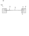
- FIG. 1 is a schematic diagram of a filtration filter 100A according to Embodiment 1 of the present invention.
- FIG. 2 is a cross-sectional view taken along line AA of the filtration filter 100A in FIG.
- the filtration filter 100 ⁇ / b> A includes a porous membrane 10 that separates an object to be filtered included in a fluid, and a holding unit 20 that holds an end of the porous membrane 10.
- the porous film 10 includes a film part 12 having a plurality of through holes 11 and an end part 13 adjacent to the film part 12. In the first embodiment, the end portion 13 of the porous membrane 10 is held by the recess 21 of the holding portion 20 so as to move in the thickness direction of the porous membrane 10.
- the filtration filter 100A is for separating the filtration object from the fluid by allowing the fluid containing the filtration object to pass through the porous membrane 10.
- the “filtering object” means an object to be filtered by the porous membrane 10.
- a biological material is used as an object to be filtered and a liquid is used as a fluid.
- the “biological substance” means a substance derived from a living organism such as a cell (eukaryotic organism), a bacterium (eubacteria), or a virus.
- cells eukaryotes
- examples of cells include eggs, sperm, induced pluripotent stem cells (iPS cells), ES cells, stem cells, mesenchymal stem cells, mononuclear cells, single cells, cell masses, suspension cells, and adhesions.
- sex cells nerve cells, leukocytes, lymphocytes, cells for regenerative medicine, autologous cells, cancer cells, circulating cancer cells (CTC), HL-60, HELA, and fungi.
- bacteria examples include gram positive bacteria, gram negative bacteria, Escherichia coli, and tuberculosis bacteria.
- viruses examples include DNA virus, RNA virus, rotavirus, (bird) influenza virus, yellow fever virus, dengue fever virus, encephalitis virus, hemorrhagic fever virus, and immunodeficiency virus.
- the filtration filter 100A is particularly excellent in separating artificial pluripotent stem cells (iPS cells), ES cells, stem cells, and circulating cancer cells (CTC) in the liquid.
- iPS cells artificial pluripotent stem cells
- ES cells ES cells
- stem cells circulating cancer cells
- the porous membrane 10 is a porous membrane that separates biological materials.
- the porous film 10 is a metal thin film composed of a film part 12 having a plurality of through holes 11 and an end part 13 adjacent to the film part 12.
- the porous film 10 is a circular metal mesh, has a pair of main surfaces facing each other, and has a plurality of through holes that penetrate both main surfaces of the film part 12.
- 11 is a structure.
- the plurality of through holes 11 are periodically arranged over the entire main surface of the film part 12.
- the porous film 10 is made of Ni, for example.
- the dimensions of the porous membrane 10 are, for example, a diameter of 6 mm and a thickness of 1.2 ⁇ m.
- the thickness of the porous film 10 is preferably 0.5 ⁇ m or more and 100 ⁇ m or less.
- the porosity is preferably 10% or more and 90% or less. More preferably, the porosity is 20% or more and 50% or less.
- the material of the porous film 10 may be gold, silver, copper, platinum, iron, nickel, chromium, stainless steel, palladium, titanium, and alloys thereof.
- the porous film 10 gold, nickel, stainless steel, and titanium are preferable from the viewpoint of biocompatibility with a biological substance when a biological substance is captured.
- the material of the porous film 10 may be an elastic material having a Young's modulus of 1 GP or more.
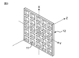
- FIG. 3 shows a schematic configuration diagram of a part of the membrane portion 12 of the porous membrane 10 which is a two-dimensional periodic structure.
- the X, Y, and Z directions in FIG. 3 indicate the vertical direction, horizontal direction, and thickness direction of the structure, respectively.
- FIG. 4 shows a view of a part of the film part 12 of FIG. 3 viewed from the Z direction.
- the film part 12 may be a plate-like structure (lattice-like structure) in which a plurality of through holes 11 are arranged at regular intervals in a matrix shape.
- the film part 12 is a plate-like structure provided with a plurality of square through holes 11 when viewed from the Z direction which is the main surface side.
- the plurality of through holes 11 are provided at equal intervals in two arrangement directions parallel to each side of the square, that is, in the X direction and the Y direction in FIG.
- the through-hole 11 is not limited to a square, For example, a rectangle, a circle
- the arrangement of the holes is not limited to the square lattice arrangement, and for example, as long as it is a square arrangement, a rectangular arrangement in which the intervals in the two arrangement directions are not equal may be used, or a triangular lattice arrangement or a quasi-periodic arrangement may be used.
- the shape and size of the through-hole 11 of the membrane part 12 are appropriately designed according to the size and shape of the biological substance to be filtered.
- the through holes 11 are, for example, square when viewed from the main surface side of the film part 12, that is, when viewed from the Z direction, and are designed to have a length of 0.1 ⁇ m to 500 ⁇ m and a width of 0.1 ⁇ m to 500 ⁇ m.
- the interval between the through holes 11 is, for example, greater than 1 time and less than or equal to 10 times that of the through holes 11, and more preferably less than or equal to 3 times that of the through holes 11.
- the aperture ratio is preferably 10% or more.
- the holding unit 20 holds the end 13 of the porous membrane 10.
- maintenance part 20 is formed with the cyclic
- the holding portion 20 is provided with a recess 21 that opens toward the porous membrane 10 in order to hold the end portion 13 of the porous membrane 10.
- the dimension of the concave portion 21 in the thickness direction of the holding portion 20 is designed to be larger than the thickness of the end portion 13.
- the dimension of the recess 21 in the thickness direction of the holding portion 20 is such that when the fluid passes through the porous film 10, the end of the end portion 13 of the porous film 10 contacts the inner wall on the upper side of the recess 21, and A part of the lower surface is designed to contact the lower inner wall of the recess 21.
- the dimension of the recess 21 in the thickness direction of the holding part 20 is such that the tip of the end 13 of the porous membrane 10 contacts the inner wall on the upper side of the recess 21 and a part of the lower surface of the end 13 is recessed. Designed to contact the lower end of 21 openings.
- the dimension of the concave portion 21 in the thickness direction of the holding portion 20 is designed to be larger than 100% and not larger than 500% with respect to the thickness of the end portion 13. More preferably, the dimension of the concave portion 21 in the thickness direction of the holding portion 20 is designed to be 200% or more and 400% or less of the thickness of the end portion 13. Thereby, it is possible to form a gap in which the porous film 10 does not escape from the holding part 20 while allowing the end 13 of the porous film 10 to move in the thickness direction of the porous film 10.
- the holding part 20 holds the end part 13 of the porous film 10 in a state where the porous film 10 is not fixed and tension is not applied.
- the holding unit 20 does not need to hold the entire circumference of the end 13 of the porous film 10.
- the holding unit 20 holds two portions facing each other at the end 13 or holds a plurality of locations at regular intervals. Form may be sufficient.
- the holding unit 20 includes two frames. Specifically, the holding unit 20 includes a first frame and a second frame. In the holding part 20 of Embodiment 1, after inserting the porous film 10 inside the first frame, the second frame is fitted to the first frame. Thereby, the porous film 10 can be held inside the holding part 20.
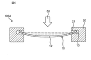
- FIG. 5 shows the operation of the filtration filter 100A when the liquid passes.
- a white arrow with a reference numeral 50 in FIG. 5 indicates a flow of liquid from the upstream side to the downstream side.
- the filtration filter 100 ⁇ / b> A when a liquid containing a biological substance passes through the porous membrane 10 in the direction 50, stress is applied in the direction 50 in the center of the membrane portion 12.
- the end 13 of the porous film 10 moves in the direction opposite to the direction 50 in the recess 21.
- the end portion 13 of the porous membrane 10 is curved and lifted in an opposite direction to the direction 50 with an angle with respect to the central portion of the membrane portion 12.
- the central portion of the porous membrane 10 is moved in the direction 50 opposite to the direction in which the end portion 13 moves. Can be bent in the direction.
- the movement of the end 13 of the porous membrane 10 is regulated by the wall surface of the recess 21. Specifically, when the end 13 of the porous membrane 10 is lifted in the direction opposite to the direction 50, the tip of the end 13 of the porous membrane 10 contacts the inner wall on the upper side of the recess 21, and the inner wall on the lower side of the recess 21. A part of the end 13 comes into contact with. That is, the tip of the end 13 is supported by the inner wall on the upper side of the recess 21, while a part of the lower surface of the end 13 is supported by the inner wall on the lower side of the recess 21. For this reason, the end portion 13 of the porous film 10 is held by the holding portion 20 without coming out of the concave portion 21.
- the amount of deflection of the film part 12 depends on the dimension of the recess 21 in the thickness direction of the holding part 20. Specifically, it depends on the size of the gap between the upper wall of the recess 21 and the end 13. When this gap increases, the amount of movement of the end portion 13 of the porous membrane 10 when the liquid passes increases, so that the amount of deflection of the membrane portion 12 increases.
- the film portion 12 bends in the direction 50 in which the liquid flows, thereby weakening the force of the liquid in the direction perpendicular to the film portion 12 and Such stress can be relaxed. That is, the filtration filter 100 ⁇ / b> A can relieve the stress applied to the film part 12 by deflecting the film part 12 to release the force in the liquid flowing direction 50 in the film part 12.
- the membrane portion 12 is held by the holding portion 20 in a state where it does not bend as shown in FIG.
- the membrane part 12 is bent to relax the stress applied to the film part 12 and from the liquid to the biological substance. The material is separated.
- the recess 21 of the holding unit 20 holds the end 13 of the porous membrane 10 so as to move in the thickness direction of the porous membrane 10. That is, the holding part 20 does not fix the porous membrane 10 and holds it without applying tension.
- the membrane portion 12 can be bent in the direction 50 in which the liquid flows.
- the filtration filter 100 ⁇ / b> A can relieve the stress applied to the film part 12 due to the bending of the film part 12 when the liquid passes, and can suppress the damage of the film part 12.
- the dimension of the concave portion 21 in the thickness direction of the holding portion 20 is designed to be larger than the thickness of the end portion 13 of the porous membrane 10.
- a gap that allows the end portion 13 of the porous film 10 to move in the thickness direction of the porous film 10 can be formed in the recess 21.
- the membrane portion 12 can be moved in the direction opposite to the moving direction of the end portion 13. Thereby, the film
- the amount of deflection of the film part 12 can be adjusted by adjusting the size of the recess 21 in the thickness direction of the holding part 20.
- the membrane portion 12 is held without being bent.
- the film part 12 bends when the liquid passes, it is possible to improve the handling property of the user.
- the user can hold the filter 20 by holding only the holding unit 20.
- the film part 12 is held in a state where it is not bent.
- the filtration filter 100A suppresses the user from touching the membrane part 12 by mistake and reduces the possibility of contamination of the membrane part 12. be able to.
- the porous film 10 is made of metal. Such a configuration can further prevent the porous membrane 10 from being damaged. Further, since the through-hole 11 is not easily deformed even when the liquid passes through the membrane part 12, it is possible to suppress the biological substance from passing through the membrane part 12 due to the deformation of the through-hole 11.
- the filter target” and the “fluid” have been described using biological materials and liquids as examples, but the present invention is not limited thereto.
- the fluid may be a gas.
- the filtering object may be, for example, a particulate material (PM10, SPM, PM2.5, etc.).
- the porous membrane 10 may be a membrane made of, for example, a membrane, a filter paper, a nonwoven fabric or the like.
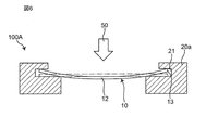
- FIG. 6 shows an operation of a modified example of the filtration filter 100A according to the first embodiment.
- the holding part 20a may be configured such that the area of the lower inner wall is larger than the area of the upper inner wall of the recess 21a.
- an area where the lower surface of the end portion 13 of the porous film 10 contacts with the inner wall on the lower side of the concave portion 21a is increased, so that when the membrane portion 12 is bent, the end portion on the inner wall on the lower side of the concave portion 21a. It becomes easy to support the lower surface of 13.
- the holding part 20 demonstrated the example provided with two frames, it is not limited to this.
- the holding unit 20 may include two or more frames.
- maintenance part 20 may be comprised by one component.
- FIG. 7 shows a schematic configuration of the filtration filter 100B of the second embodiment.
- the same or equivalent components as those in the first embodiment will be described with the same reference numerals.
- descriptions overlapping with those in the first embodiment are omitted.
- the filtration filter 100B of the second embodiment is different from the filtration filter 100A of the first embodiment in the configuration for holding the porous membrane 10.
- the holding hole 14 is provided in the end portion 13 of the porous film 10, and the protruding portion 22 is provided in the holding portion 20 instead of the concave portion 21.
- the holding hole 14 is a hole for inserting the protrusion 22 and is provided at the end 13 of the porous film 10.
- the holding hole 14 is a hole that allows communication between two opposing main surfaces of the porous film 10.
- the holding hole 14 has a circular shape when viewed from the main surface side of the porous film 10.
- the diameter of the holding hole 14 is designed to be larger than the diameter of the protrusion 22.
- the plurality of holding holes 14 are provided at equal intervals with each other at the end portions 13 on the concentric circles of the porous film 10 when viewed from the main surface side of the porous film 10 that is, for example, a circular metal mesh. ing.
- the protrusion 22 holds the end 13 of the porous film 10 by being inserted into the holding hole 14 of the porous film 10.
- the protruding portion 22 protrudes in the thickness direction of the holding portion 20 on the upper surface of the holding portion 20.
- a plurality of protrusions 22 are provided at positions corresponding to the holding holes 14 of the porous film 10.
- the protrusion 22 is, for example, a conical pin.
- the diameter of the protrusion 22 is designed to be smaller than the diameter of the holding hole 14. That is, the diameter of the holding hole 14 is designed to be larger than the diameter of the protruding portion 22.
- the diameter of the holding hole 14 is designed to be greater than 100% and 200% or less with respect to the diameter of the protruding portion 22. .
- the height of the protrusion 22 in the thickness direction of the holding portion 20 is designed to a height that prevents the holding hole 14 from coming out of the protrusion 22.
- the height of the protrusion 22 is appropriately determined according to dimensions such as the diameter of the holding hole 14 and the diameter of the porous film 10.
- FIG. 8 shows the operation of the filtration filter 100B when the liquid passes.
- a white arrow with a reference numeral 50 in FIG. 8 indicates the flow of liquid from the upstream side to the downstream side.
- stress is applied in the direction 50 in the center of the membrane portion 12.
- the end 13 of the porous film 10 moves in the direction opposite to the direction 50 along the outer wall of the protrusion 22 inserted into the holding hole 14.
- the end portion 13 of the porous membrane 10 is curved and lifted in an opposite direction to the direction 50 with an angle with respect to the central portion of the membrane portion 12.
- the end 13 of the porous membrane 10 can move in the thickness direction of the porous membrane 10 without being fixed, so that the central portion of the membrane 12 can be bent in the direction 50.
- the protrusion 22 functions as a stopper of the porous film 10 while restricting the movement of the end 13 of the porous film 10.
- the amount of bending of the membrane portion 12 depends on the diameter of the holding hole 14. Specifically, it depends on the size of the gap between the inner wall of the holding hole 14 and the outer wall of the protrusion 22. When this gap increases, the amount of movement of the end portion 13 of the porous membrane 10 when the liquid passes increases, so that the amount of deflection of the membrane portion 12 increases.
- the holding unit 20 holds the porous membrane 10 by inserting the protrusions 22 of the holding unit 20 into the holding holes 14 provided in the end 13 of the porous membrane 10. Further, since the diameter of the holding hole 14 is larger than the diameter of the protruding portion 22, when the protruding portion 22 is inserted into the holding hole 14, a gap can be formed between the inner wall of the holding hole 14 and the protruding portion 22. . With such a configuration, when the liquid passes through the filtration filter 100B, the end portion 13 of the porous membrane 10 is moved at an angle in the thickness direction of the porous membrane 10, thereby causing the membrane portion 12 to flow in the liquid direction 50. Can be bent. As a result, the filtration filter 100B can relieve the stress applied to the film part 12 due to the bending of the film part 12 when the liquid passes, and can suppress the damage of the film part 12.
- the amount of deflection of the membrane portion 12 can be adjusted by adjusting the diameter of the holding hole 14 and the diameter of the protrusion 22.
- the holding hole 14 has been described as having a circular shape when viewed from the main surface side of the porous film 10, but the present invention is not limited to this.
- the holding hole 14 may have any shape as long as the protrusion 22 can be inserted.
- the holding hole 14 may have any shape such as a triangle, a quadrangle, a trapezoid, and an ellipse.
- the holding hole 14 may be a long hole extending in the center direction of the porous film 10.
- the protrusion 22 has been described by taking a conical pin as an example, but is not limited thereto.
- the protrusion 22 has a shape that can hold the porous film 10 while being inserted into the holding hole 14 of the porous film 10 while allowing the end 13 of the porous film 10 to move in the thickness direction of the porous film 10. Good.
- the protrusion 22 may have a shape such as a triangular prism, a quadrangular prism, or a cylinder.
- the protrusion part 22 demonstrated the structure provided in the upper surface of the holding
- the protrusion 22 may be provided in the recess 21 of the first embodiment. With such a configuration, the end portion 13 of the porous film 10 can be held by the concave portion 21 and the protruding portion 22, so that the porous film 10 can be held while the film portion 12 is bent more reliably.
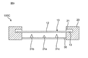
- FIG. 9 shows a schematic configuration of a filtration filter 100C according to the third embodiment.
- FIG. 10 shows a schematic configuration of the holding unit 20 according to the third embodiment. In FIG. 10, the film portion 10 is omitted for the sake of simplicity.
- the filtration filter 100C according to the third embodiment is different from the filtration filter 100A according to the first embodiment in that a support portion 30 is provided.
- the support part 30 supports the bent film part 12 when the liquid passes through the filtration filter 100C. As shown in FIGS. 9 and 10, the support portion 30 is disposed at a position away from the main surface of the film portion 12 in the thickness direction. Specifically, it is provided on the inner wall of the holding part 20 and is arranged on the downstream side of the film part 12.
- the support portion 30 includes two plate-like members, and each member is arranged so as to intersect at a position corresponding to the central portion of the membrane portion 12.
- a plurality of protrusions 31a, 31b, 31c, 31d, and 31e are provided on the surface of the support part 30 on the film part 12 side.
- the protrusion 31a is arranged at a position corresponding to the center of the film part 12, that is, at a position where two plate-like members intersect.
- the protrusions 31b, 31c, 31d, and 31e are disposed at a predetermined distance from the protrusion 31a.
- the plurality of protrusions 31a to 31e are arranged so as to contact the film part 12 along the shape of the film part 12 when bent.
- the plurality of protrusions 31a to 31e are distances between the tips of the protrusions 31a to 31e and the main surface of the film part 12 from the center of the film part 12 to the outside. Is designed to be small.
- the height of the protrusion 31a in the thickness direction of the film part 10 is designed to be smaller than the height of the protrusions 31b, 31c, 31d, and 31e.
- the plurality of protrusions 31a to 31e are, for example, conical pins.
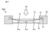
- FIG. 11 shows the operation of the filtration filter 100C during liquid passage.
- a white arrow with a reference numeral 50 in FIG. 11 indicates the flow of liquid from the upstream side to the downstream side.
- the filtration filter 100 ⁇ / b> C when the liquid containing the biological substance passes through the film part 12 in the direction 50, stress is applied in the direction 50 in the center of the film part 12, and the film part 12. The center portion of the wire is bent in the direction 50.
- the bent film portion 12 comes into contact with the tips of the plurality of protrusions 31a to 31e of the support portion 30. In this manner, the support portion 30 contacts the film portion 12 bent by the plurality of protrusions 31a to 31e, and suppresses the film portion 12 from being bent excessively.
- the plurality of protrusions 31 a to 31 e of the support part 30 come into contact with the crosspieces of the film part 12 when the fluid passes through the film part 12.
- the crosspiece of the film part 12 is a part where the through hole 11 is not formed in the film part 12.
- the holding part 20 has a support part 30 that supports the film part 10 bent when the liquid passes through. Further, in the support part 30, a plurality of protrusions 31a to 31e protruding toward the film part 12 are arranged so as to contact the bent film part 12. With such a configuration, it is possible to prevent the film portion 12 from being bent excessively when the liquid passes. As a result, it is possible to suppress stress concentration due to excessive bending of the film part 12. In addition, by adopting a configuration in which the plurality of protrusions 31 a to 31 e are provided on the surface of the support part 30, the support part 30 can support the film part 12 by dispersing stress applied to the film part 12.
- the plurality of protrusions 31a to 31e are designed such that the distance between the tip of the protrusion and the main surface of the film part 12 decreases from the center of the film part 10 toward the outside.
- the plurality of protrusions 31a to 31e come into contact with the film part 12 along the shape of the film part 12 in a bent state when the liquid passes. Therefore, the stress applied to the film part 12 can be more evenly distributed by the protrusions 31a to 31e.
- the filtration filter 100 ⁇ / b> C can reliably suppress damage to the membrane portion 12.
- the film portion 12 can be supported without hindering the flow of the liquid.
- FIG. 12 shows a schematic configuration of another filtration filter according to the third embodiment. As shown in FIG. 12, it is good also as a structure which added the support part 30 to the structure of Embodiment 2.
- FIG. 12 shows a schematic configuration of another filtration filter according to the third embodiment. As shown in FIG. 12, it is good also as a structure which added the support part 30 to the structure of Embodiment 2.
- the support 30 has been described as having a plurality of protrusions 31a to 31e, but is not limited thereto.
- the number of protrusions can be set to an arbitrary number depending on the size of the film part 12 and the like.
- the support unit 30 may have, for example, a configuration having no projection, a configuration having only one projection, or a configuration having more than five projections.
- FIG. 13 shows a schematic configuration of another holding unit 20 in the third embodiment. As shown in FIG. 13, for example, the support portion 30 may be provided with one protrusion 31 a at a position corresponding to the center of the film portion 12.
- the support 30 has been described with respect to the example in which the conical pin-shaped protrusions 31a to 31e are arranged on the plate-like member, but the present invention is not limited to this.
- the support part 30 should just be a shape which can contact the film
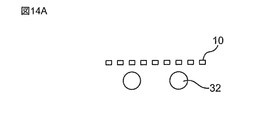
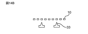
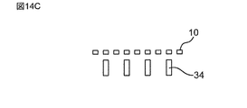
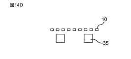
- 14A to 14E show modifications of the support portion in the third embodiment. As shown in FIGS. 14A to 14E, the support section 32 having a circular cross-section cut in the direction of fluid flow, the acute triangular support section 33, the rectangular support section 34, the square support section 35, and The support part 36 of an inverted T shape may be sufficient.
- a support part having a large surface area in contact with the main surface of the film part 12, for example, a support part 32 having a circular cross section and a square support part 35 shown in FIGS. 14A and 14D is used. May be.
- a support part 33, a rectangular support part 34, and an inverted T-shaped support part 36 may be used.
- the present invention is an invention relating to a filtration filter, and is excellent in that it prevents breakage of the filtration filter when a fluid passes through. For example, by taking out cells from a biological specimen, it can be used for medical diagnosis, or PM2.5 present in the air can be captured and used for environmental measures.
Landscapes
- Chemical & Material Sciences (AREA)
- Life Sciences & Earth Sciences (AREA)
- Chemical Kinetics & Catalysis (AREA)
- Engineering & Computer Science (AREA)
- Health & Medical Sciences (AREA)
- Wood Science & Technology (AREA)
- Bioinformatics & Cheminformatics (AREA)
- Organic Chemistry (AREA)
- Zoology (AREA)
- Biotechnology (AREA)
- Biochemistry (AREA)
- Sustainable Development (AREA)
- Microbiology (AREA)
- General Engineering & Computer Science (AREA)
- General Health & Medical Sciences (AREA)
- Genetics & Genomics (AREA)
- Biomedical Technology (AREA)
- Geology (AREA)
- Molecular Biology (AREA)
- Separation Using Semi-Permeable Membranes (AREA)
- Combined Means For Separation Of Solids (AREA)
- Filtering Of Dispersed Particles In Gases (AREA)
- Separation Of Solids By Using Liquids Or Pneumatic Power (AREA)
- Filtration Of Liquid (AREA)
- Filtering Materials (AREA)
Abstract
フィルターにかかる応力を緩和し、フィルターの破損を抑制することができる濾過フィルターを提供する。本発明の濾過フィルターは、流体中の濾過対象物を分離する濾過フィルターであって、複数の貫通孔を有する膜部、及び膜部に隣接する端部からなる多孔膜と、多孔膜の端部が多孔膜の厚み方向に動くと共に膜部が端部の動く方向と反対方向へ動くように、端部を保持する保持部と、を備える。このような構成により、本発明の濾過フィルターは、多孔膜の端部を厚み方向に動かすことによって膜部を撓ませ、膜部にかかる応力を緩和する。
Description
本発明は、流体中の濾過対象物を濾過する濾過フィルターに関する。
近年、流体中の濾過対象物を濾過するフィルターの使用例として、細胞捕捉システムが開示されている(例えば、特許文献1参照。)。特許文献1に開示された細胞捕捉システムは、細胞を捕捉するためのフィルターを、張力をかけた状態で蓋部材と収納部材との間に嵌合している。特許文献1に開示された細胞捕捉システムでは、張力をかけた状態のフィルターに、細胞を含む流体を通過させることで細胞を捕捉している。
特許文献1の細胞捕捉システムにおいては、張力をかけた状態でフィルターを保持している。そのため、特許文献1の細胞捕捉システムにおいては、流体がフィルターを通過する際に、フィルターにかかる応力によってフィルターが破損するという課題がある。
本発明は、上記の課題を解決するものであり、フィルターにかかる応力を緩和し、フィルターの破損を抑制することができる濾過フィルターを提供することを目的とする。
本発明の一態様の濾過フィルターは、
流体中の濾過対象物を分離する濾過フィルターであって、
複数の貫通孔を有する膜部、及び前記膜部に隣接する端部からなる多孔膜と、
前記多孔膜の端部が前記多孔膜の厚み方向に動くと共に前記膜部が前記端部の動く方向と反対方向へ動くように、前記端部を保持する保持部と、
を備える。
流体中の濾過対象物を分離する濾過フィルターであって、
複数の貫通孔を有する膜部、及び前記膜部に隣接する端部からなる多孔膜と、
前記多孔膜の端部が前記多孔膜の厚み方向に動くと共に前記膜部が前記端部の動く方向と反対方向へ動くように、前記端部を保持する保持部と、
を備える。
本発明によれば、フィルターにかかる応力を緩和し、フィルターの破損を抑制することができる濾過フィルターを提供することができる。
本発明の一態様の濾過フィルターは、
流体中の濾過対象物を分離する濾過フィルターであって、
複数の貫通孔を有する膜部、及び前記膜部に隣接する端部からなる多孔膜と、
前記多孔膜の端部が前記多孔膜の厚み方向に動くと共に前記膜部が前記端部の動く方向と反対方向へ動くように、前記端部を保持する保持部と、
を備えてもよい。
流体中の濾過対象物を分離する濾過フィルターであって、
複数の貫通孔を有する膜部、及び前記膜部に隣接する端部からなる多孔膜と、
前記多孔膜の端部が前記多孔膜の厚み方向に動くと共に前記膜部が前記端部の動く方向と反対方向へ動くように、前記端部を保持する保持部と、
を備えてもよい。
このような構成により、多孔膜の端部が多孔膜の厚み方向に動くと共に膜部が端部の動く方向と反対方向に動くことによって、膜部を撓ませることができる。このように、膜部を撓ませることによって膜部にかかる応力を緩和することができるため、濾過フィルターの破損を抑制することができる。
前記多孔膜は、金属からなっていてもよい。
このような構成により、濾過フィルターの破損を更に抑制することができる。また、膜部に応力がかかったときに膜部の貫通孔が変形するのを抑制することができる。
前記端部は、保持孔を有し、
前記保持部は、前記保持孔に挿入される第1突起部を有し、
前記保持孔の径は、前記第1突起部の径より大きくてもよい。
前記保持部は、前記保持孔に挿入される第1突起部を有し、
前記保持孔の径は、前記第1突起部の径より大きくてもよい。
このような構成により、多孔膜の端部の保持孔に保持部の第1突起部を挿入することによって、保持部によって多孔膜の端部を確実に保持することができる。また、保持孔の径が第1突起部の径よりも大きいため、多孔膜の端部の厚み方向への動きを許容して膜部を端部の動く方向と反対方向へ動かすことによって、膜部を確実に撓ませることができる。
前記保持部は、前記端部を保持するために前記膜部に向かって開口する凹部を有し、
前記保持部の厚み方向における前記凹部の寸法は、前記端部の厚みよりも大きくてもよい。
前記保持部の厚み方向における前記凹部の寸法は、前記端部の厚みよりも大きくてもよい。
このような構成により、保持部の凹部によって多孔膜の端部を確実に保持することができる。また、保持部の厚み方向における凹部の寸法が端部の厚みより大きいため、多孔膜の端部の厚み方向への動きを許容し、膜部を端部の動く方向と反対方向へ動かすことによって、膜部を撓ませることができる。
前記保持部は、前記膜部の主面に対して前記膜部の厚み方向に離れた位置に支持部を有し、
前記支持部は、流体が前記膜部を通過する際に前記膜部接触するように配置されてもよい。
前記支持部は、流体が前記膜部を通過する際に前記膜部接触するように配置されてもよい。
このような構成により、流体が膜部を通過する際に、支持部が膜部に接触することで膜部が撓みすぎないように規制することができる。その結果、膜部の撓みによって応力集中が生じることを抑制することができる。
前記支持部は、前記膜部側に突出した第2突起部を有してもよい。
このような構成により、流体が膜部を通過する際に、第2突起部が膜部に接触することで、支持部によって流体の流れが妨げられることを抑制することができる。
前記第2突起部は、複数設けられ、
複数の前記第2突起部は、前記膜部の中央から外側へ向かって前記第2突起部と前記膜部の主面との間の距離が小さくなるように設けられてもよい。
複数の前記第2突起部は、前記膜部の中央から外側へ向かって前記第2突起部と前記膜部の主面との間の距離が小さくなるように設けられてもよい。
このような構成により、流体が膜部を通過する際に、複数の第2突起部が膜部に接触することによって膜部にかかる応力を分散することができる。また、膜部の中央から外側へ向かって第2突起部と膜部の主面との間の距離が小さくなることで、それぞれの突起部で膜部にかかる応力を均等に分散することができる。
前記支持部は、前記流体が前記膜部を通過する際に前記膜部の桟部に接触してもよい。
このような構成により、支持部が膜部の桟部に接触することによって、流体の流れを妨げずに膜部の撓みを規制することができる。
以下、本発明に係る実施の形態について、添付の図面を参照しながら説明する。また、各図においては、説明を容易なものとするため、各要素を誇張して示している。
(実施の形態1)
[全体構成]
図1は、本発明に係る実施の形態1の濾過フィルター100Aの概略図を示す。図2は、図1中の濾過フィルター100AのA-A線断面図を示す。図1及び図2に示すように、濾過フィルター100Aは、流体に含まれる濾過対象物を分離する多孔膜10と、多孔膜10の端部を保持する保持部20とを備える。多孔膜10は、複数の貫通孔11を有する膜部12と、膜部12に隣接する端部13とからなる。実施の形態1において、多孔膜10の端部13は、保持部20の凹部21によって多孔膜10の厚み方向に動くように保持されている。
[全体構成]
図1は、本発明に係る実施の形態1の濾過フィルター100Aの概略図を示す。図2は、図1中の濾過フィルター100AのA-A線断面図を示す。図1及び図2に示すように、濾過フィルター100Aは、流体に含まれる濾過対象物を分離する多孔膜10と、多孔膜10の端部を保持する保持部20とを備える。多孔膜10は、複数の貫通孔11を有する膜部12と、膜部12に隣接する端部13とからなる。実施の形態1において、多孔膜10の端部13は、保持部20の凹部21によって多孔膜10の厚み方向に動くように保持されている。
濾過フィルター100Aは、多孔膜10に濾過対象物を含む流体を通過させることによって、流体中から濾過対象物を分離するものである。本明細書において、「濾過対象物」とは、多孔膜10によって濾過する対象物を意味する。実施の形態1においては、濾過対象物として生物由来物質を用い、流体として液体を用いて説明する。
なお、本明細書において、「生物由来物質」とは、細胞(真核生物)、細菌(真性細菌)、ウィルス等の生物に由来する物質を意味する。細胞(真核生物)としては、例えば、卵、精子、人工多能性幹細胞(iPS細胞)、ES細胞、幹細胞、間葉系幹細胞、単核球細胞、単細胞、細胞塊、浮遊性細胞、接着性細胞、神経細胞、白血球、リンパ球、再生医療用細胞、自己細胞、がん細胞、血中循環がん細胞(CTC)、HL-60、HELA、菌類を含む。細菌(真性細菌)としては、例えば、グラム陽性菌、グラム陰性菌、大腸菌、結核菌を含む。ウィルスとしては、例えば、DNAウィルス、RNAウィルス、ロタウィルス、(鳥)インフルエンザウィルス、黄熱病ウィルス、デング熱病ウィルス、脳炎ウィルス、出血熱ウィルス、免疫不全ウィルスを含む。実施の形態1においては、濾過フィルター100Aは、特に、人工多能性幹細胞(iPS細胞)、ES細胞、幹細胞、血中循環がん細胞(CTC)、を液体中から分離するのに優れる。
<多孔膜>
多孔膜10は、生物由来物質を分離する多孔膜である。具体的には、多孔膜10は、複数の貫通孔11を有する膜部12と、膜部12に隣接する端部13とからなる金属製薄膜である。図1に示すように、実施の形態1において、多孔膜10は、円形の金属メッシュであり、互いに対向する一対の主面を有し、膜部12の両主面を貫通する複数の貫通孔11を有する構造体である。複数の貫通孔11は、膜部12の主面上の全体にわたって周期的に配置されている。多孔膜10は、例えば、Niで形成されている。多孔膜10の寸法は、例えば、直径6mm、厚さ1.2μmである。多孔膜10の厚みは、0.5μm以上100μm以下が好ましい。空隙率は、10%以上90%以下が好ましい。より好ましくは、空隙率は20%以上50%以下である。このような構成により、濾過対象物を含む流体を多孔膜10に通過させたときに多孔膜10を撓み易くすることができる一方、流体を多孔膜10に通過させていないとき、多孔膜10が撓みにくいようにすることができる。多孔膜10の材料は、金、銀、銅、白金、鉄、ニッケル、クロム、ステンレス鋼、パラジウム、チタン、およびこれらの合金であってもよい。特に、多孔膜10の材料としては、生物由来物質を捕捉する場合、生物由来物質との生体親和性の観点から、金、ニッケル、ステンレス、チタンが好ましい。また、多孔膜10の材料は、ヤング率が1GP以上の弾性体材料であってもよい。
多孔膜10は、生物由来物質を分離する多孔膜である。具体的には、多孔膜10は、複数の貫通孔11を有する膜部12と、膜部12に隣接する端部13とからなる金属製薄膜である。図1に示すように、実施の形態1において、多孔膜10は、円形の金属メッシュであり、互いに対向する一対の主面を有し、膜部12の両主面を貫通する複数の貫通孔11を有する構造体である。複数の貫通孔11は、膜部12の主面上の全体にわたって周期的に配置されている。多孔膜10は、例えば、Niで形成されている。多孔膜10の寸法は、例えば、直径6mm、厚さ1.2μmである。多孔膜10の厚みは、0.5μm以上100μm以下が好ましい。空隙率は、10%以上90%以下が好ましい。より好ましくは、空隙率は20%以上50%以下である。このような構成により、濾過対象物を含む流体を多孔膜10に通過させたときに多孔膜10を撓み易くすることができる一方、流体を多孔膜10に通過させていないとき、多孔膜10が撓みにくいようにすることができる。多孔膜10の材料は、金、銀、銅、白金、鉄、ニッケル、クロム、ステンレス鋼、パラジウム、チタン、およびこれらの合金であってもよい。特に、多孔膜10の材料としては、生物由来物質を捕捉する場合、生物由来物質との生体親和性の観点から、金、ニッケル、ステンレス、チタンが好ましい。また、多孔膜10の材料は、ヤング率が1GP以上の弾性体材料であってもよい。
図3は、2次元周期構造体である多孔膜10の膜部12の一部の概略構成図を示す。図3中のX、Y、Z方向は、それぞれ構造体の縦方向、横方向、厚み方向を示している。図4は、図3の膜部12の一部をZ方向から見た図を示す。図3及び図4に示すように、膜部12は、マトリックス状に一定の間隔で複数の貫通孔11が配置された板状構造体(格子状構造体)であってもよい。膜部12は、その主面側であるZ方向から見て正方形の貫通孔11が複数設けられた板状構造体である。複数の貫通孔11は、正方形の各辺と平行な2つの配列方向、即ち図3中のX方向とY方向に等しい間隔で設けられている。なお、貫通孔11は、正方形に限定されず、例えば長方形や円や楕円などでもよい。また、孔の配列も正方格子配列に限定されず、例えば方形配列であれば、2つの配列方向の間隔は等しくない長方形配列でもよく、三角格子配列や準周期配列などでもよい。
膜部12の貫通孔11の形状や寸法は、濾過する生物由来物質の大きさ、形状に応じて適宜設計されるものである。貫通孔11は、例えば、膜部12の主面側から見て、即ちZ方向から見て正方形であり、縦0.1μm以上500μm以下、横0.1μm以上500μm以下に設計される。貫通孔11間の間隔は、例えば、貫通孔11の1倍より大きく10倍以下であり、より好ましくは貫通孔11の3倍以下である。あるいは、開口率にして10%以上が好ましい。
<保持部>
保持部20は、多孔膜10の端部13を保持するものである。図1に示すように、実施の形態1において、保持部20は、環状の部材で形成されている。図2に示すように、保持部20には、多孔膜10の端部13を保持するために多孔膜10に向かって開口する凹部21が設けられている。保持部20の厚み方向における凹部21の寸法は、端部13の厚みよりも大きく設計されている。また、保持部20の厚み方向における凹部21の寸法は、多孔膜10に流体が通過する際、多孔膜10の端部13の先端が凹部21の上側の内壁に接触すると共に、端部13の下面の一部が凹部21の下側の内壁に接触するように設計されている。実施の形態1では、保持部20の厚み方向における凹部21の寸法は、多孔膜10の端部13の先端が凹部21の上側の内壁に接触すると共に、端部13の下面の一部が凹部21の開口の下側端部に接触するように設計されている。このように凹部21の寸法を設計することにより、膜部12が撓んだとき、凹部21の上側の内壁と下側の内壁とが、多孔膜10の端部13を保持することができる。
保持部20は、多孔膜10の端部13を保持するものである。図1に示すように、実施の形態1において、保持部20は、環状の部材で形成されている。図2に示すように、保持部20には、多孔膜10の端部13を保持するために多孔膜10に向かって開口する凹部21が設けられている。保持部20の厚み方向における凹部21の寸法は、端部13の厚みよりも大きく設計されている。また、保持部20の厚み方向における凹部21の寸法は、多孔膜10に流体が通過する際、多孔膜10の端部13の先端が凹部21の上側の内壁に接触すると共に、端部13の下面の一部が凹部21の下側の内壁に接触するように設計されている。実施の形態1では、保持部20の厚み方向における凹部21の寸法は、多孔膜10の端部13の先端が凹部21の上側の内壁に接触すると共に、端部13の下面の一部が凹部21の開口の下側端部に接触するように設計されている。このように凹部21の寸法を設計することにより、膜部12が撓んだとき、凹部21の上側の内壁と下側の内壁とが、多孔膜10の端部13を保持することができる。
例えば、保持部20の厚み方向における凹部21の寸法は、端部13の厚さに対して100%より大きく500%以下で設計されている。より好ましくは、保持部20の厚み方向における凹部21の寸法は、端部13の厚みの200%以上400%以下で設計されている。これにより、多孔膜10の端部13が多孔膜10の厚み方向に動くことを許容しつつ、保持部20から多孔膜10が抜け出さない隙間を形成することができる。このように、保持部20では、多孔膜10を固定せず、張力をかけない状態で多孔膜10の端部13を保持している。なお、保持部20は、多孔膜10の端部13の全周を保持する必要はなく、例えば、端部13において対向する2箇所部分を保持する形態や、一定間隔ごとに複数箇所を保持する形態であってもよい。
実施の形態1では、保持部20は、2つの枠体を備える。具体的には、保持部20は、第1枠体と第2枠体とを備える。実施の形態1の保持部20では、第1枠体の内部に多孔膜10を挿入した後、第2枠体を第1枠体に嵌合している。これにより、多孔膜10を保持部20の内部に保持することができる。
[液体通過時の濾過フィルターの動作]
図5は、液体通過時における濾過フィルター100Aの動作を示す。図5中の符号50が付された白矢印は、上流側から下流側への液体の流れを示す。図5に示すように、濾過フィルター100Aにおいて、生物由来物質を含む液体が方向50の向きに多孔膜10を通過すると、膜部12の中央部において方向50の向きに応力がかかる。このとき、凹部21内では、多孔膜10の端部13が方向50と逆向きに動く。具体的には、多孔膜10の端部13は、膜部12の中央部に対して角度を有して方向50と逆向きに湾曲して持ち上がる。このように、多孔膜10の端部13が固定されずに多孔膜10の厚み方向に動くことができるため、多孔膜10の中央部を、端部13の動く方向と反対方向の方向50の向きに撓ませることができる。
図5は、液体通過時における濾過フィルター100Aの動作を示す。図5中の符号50が付された白矢印は、上流側から下流側への液体の流れを示す。図5に示すように、濾過フィルター100Aにおいて、生物由来物質を含む液体が方向50の向きに多孔膜10を通過すると、膜部12の中央部において方向50の向きに応力がかかる。このとき、凹部21内では、多孔膜10の端部13が方向50と逆向きに動く。具体的には、多孔膜10の端部13は、膜部12の中央部に対して角度を有して方向50と逆向きに湾曲して持ち上がる。このように、多孔膜10の端部13が固定されずに多孔膜10の厚み方向に動くことができるため、多孔膜10の中央部を、端部13の動く方向と反対方向の方向50の向きに撓ませることができる。
多孔膜10の端部13の動きは、凹部21の壁面によって規制される。具体的には、多孔膜10の端部13が方向50と逆向きに持ち上がると、凹部21の上側の内壁に多孔膜10の端部13の先端が接触すると共に、凹部21の下側の内壁に端部13の一部が接触する。即ち、端部13の先端が凹部21の上側の内壁で支持される一方、端部13の下面の一部が凹部21の下側の内壁で支持される。このため、多孔膜10の端部13が凹部21から抜け出すことなく保持部20によって保持される。膜部12の撓み量は、保持部20の厚み方向における凹部21の寸法に依存する。具体的には、凹部21の上壁と端部13との間の隙間の寸法に依存する。この隙間が大きくなると、液体通過時における多孔膜10の端部13の動く量が増えるため、膜部12の撓み量が大きくなる。
このように、液体が濾過フィルター100Aを通過する際に、膜部12が液体の流れる方向50に撓むことによって、膜部12に対して垂直方向の液体の力を弱めて、膜部12にかかる応力を緩和することができる。即ち、濾過フィルター100Aは、膜部12を撓ませることによって、膜部12において液体の流れる方向50への力を逃がし、膜部12にかかる応力を緩和することができる。また、液体が濾過フィルター100Aを通過していないときは、膜部12は、図2に示すように、撓まない状態で保持部20に保持される。
以上のように、濾過フィルター100Aでは、生物由来物質を含む液体を多孔膜10に通過させたときに、膜部12を撓ませることによって膜部12にかかる応力を緩和しつつ、液体から生物由来物質を分離している。
[効果]
実施の形態1に係る濾過フィルター100Aによれば、以下の効果を奏することができる。
実施の形態1に係る濾過フィルター100Aによれば、以下の効果を奏することができる。
濾過フィルター100Aにおいて、保持部20の凹部21は、多孔膜10の端部13を多孔膜10の厚み方向に動くように保持している。即ち、保持部20は、多孔膜10を固定せず、張力をかけない状態で保持している。このような構成により、液体が濾過フィルター100Aを通過する際に、液体の流れる方向50に膜部12を撓ませることができる。その結果、濾過フィルター100Aは、液体が通過する際に、膜部12の撓みによって膜部12にかかる応力を緩和し、膜部12の破損を抑制することができる。
濾過フィルター100Aにおいては、保持部20の厚み方向における凹部21の寸法は、多孔膜10の端部13の厚さより大きく設計されている。このような構成により、凹部21内に多孔膜10の端部13が多孔膜10の厚み方向に動くことを許容する隙間を形成することができる。この隙間内で多孔膜10の端部13が、多孔膜10の厚み方向に動くことによって、膜部12を端部13の動く方向と反対方向へ動かすことができる。これにより、膜部12を確実に撓ませることができる。また、濾過フィルター100Aにおいては、保持部20の厚み方向における凹部21の寸法を調整することによって、膜部12の撓み量を調整することができる。
濾過フィルター100Aにおいては、液体が多孔膜10を通過していないときは、膜部12が撓まない状態で保持されている。このように、濾過フィルター100Aでは、液体通過時に膜部12が撓む構成であるため、ユーザのハンドリング性を向上させることができる。例えば、濾過フィルター100Aを濾過装置に取り付ける際などにおいて、ユーザは保持部20のみを持って取り付けを行うことができる。このとき、膜部12は撓まない状態で保持されている。このため、膜部12が常時撓んだ状態となる濾過フィルターと比べて、濾過フィルター100Aは、ユーザが誤って膜部12に触れることを抑制し、膜部12の汚染の可能性を低減することができる。
多孔膜10は、金属からなる。このような構成により、更に多孔膜10が破損することを抑制することができる。また、液体が膜部12を通過する際においても、貫通孔11が変形しにくいため、貫通孔11の変形により生物由来物質が膜部12を通過してしまうのを抑制することができる。
なお、実施の形態1において、「濾過対象物」及び「流体」は、一例として、それぞれ生物由来物質及び液体を用いて説明したが、これに限定されない。流体は、気体であってもよい。濾過対象物は、例えば、粒子状物質(PM10やSPMやPM2.5等)であってもよい。
実施の形態1において、多孔膜10として金属製薄膜を用いているが、これに限定されない。多孔膜10は、例えば、メンブレン、ろ紙、不織布等からなる膜であってもよい。
図6は、実施の形態1に係る濾過フィルター100Aの変形例の動作を示す。図6に示すように、保持部20aは、凹部21aの上側の内壁の面積よりも下側の内壁の面積の方が大きい構成としてもよい。このような構成により、凹部21aの下側の内壁で多孔膜10の端部13の下面が接触する面積が増えるため、膜部12が撓んだとき、凹部21aの下側の内壁で端部13の下面を支持しやすくなる。
実施の形態1では、保持部20は、2つの枠体を備える例について説明したが、これに限定されない。例えば、保持部20は、2つ以上の枠体を備えていてもよい。また、保持部20は、1つの部品で構成されていてもよい。
(実施の形態2)
[全体構成]
本発明に係る実施の形態2の濾過フィルターについて図7を用いて説明する。
図7は、実施の形態2の濾過フィルター100Bの概略構成を示す。実施の形態2では、主に実施の形態1と異なる点について説明する。実施の形態2においては、実施の形態1と同一又は同等の構成については同じ符号を付して説明する。また、実施の形態2では、実施の形態1と重複する記載は省略する。
[全体構成]
本発明に係る実施の形態2の濾過フィルターについて図7を用いて説明する。
図7は、実施の形態2の濾過フィルター100Bの概略構成を示す。実施の形態2では、主に実施の形態1と異なる点について説明する。実施の形態2においては、実施の形態1と同一又は同等の構成については同じ符号を付して説明する。また、実施の形態2では、実施の形態1と重複する記載は省略する。
図7に示すように、実施の形態2の濾過フィルター100Bは、実施の形態1の濾過フィルター100Aと比べて、多孔膜10を保持する構成が異なる。具体的には、多孔膜10の端部13に保持孔14を設けると共に、保持部20に凹部21の代わりに突起部22を設けている。
<保持孔>
保持孔14は、突起部22を挿入するための孔であり、多孔膜10の端部13に設けられている。保持孔14は、多孔膜10の対向する2つの主面を連通する孔である。保持孔14は、多孔膜10の主面側から見て円形の形状を有する。保持孔14の径は、突起部22の径よりも大きく設計されている。実施の形態2においては、複数の保持孔14が、例えば、円形の金属メッシュである多孔膜10の主面側から見て、多孔膜10の同心円上の端部13に互いに等間隔で設けられている。
保持孔14は、突起部22を挿入するための孔であり、多孔膜10の端部13に設けられている。保持孔14は、多孔膜10の対向する2つの主面を連通する孔である。保持孔14は、多孔膜10の主面側から見て円形の形状を有する。保持孔14の径は、突起部22の径よりも大きく設計されている。実施の形態2においては、複数の保持孔14が、例えば、円形の金属メッシュである多孔膜10の主面側から見て、多孔膜10の同心円上の端部13に互いに等間隔で設けられている。
<突起部>
突起部22は、多孔膜10の保持孔14に挿入されることによって、多孔膜10の端部13を保持するものである。突起部22は、保持部20の上面において、保持部20の厚み方向に突出している。実施の形態2においては、突起部22は、例えば、多孔膜10の保持孔14に対応する位置に複数設けられている。
突起部22は、多孔膜10の保持孔14に挿入されることによって、多孔膜10の端部13を保持するものである。突起部22は、保持部20の上面において、保持部20の厚み方向に突出している。実施の形態2においては、突起部22は、例えば、多孔膜10の保持孔14に対応する位置に複数設けられている。
突起部22は、例えば、円錐ピンである。突起部22の径は、保持孔14の径より小さく設計されている。即ち、保持孔14の径は、突起部22の径より大きく設計されており、例えば、保持孔14の径は、突起部22の径に対して100%より大きく200%以下で設計されている。これにより、突起部22が保持孔14に挿入されたときに、保持孔14の内壁と突起部22との間に多孔膜10の端部13が多孔膜10の厚み方向に動くことを許容する隙間を形成することができる。また、保持部20の厚み方向における突起部22の高さは、保持孔14が突起部22から抜け出さない程度の高さに設計されている。突起部22の高さは、保持孔14の径、多孔膜10の径などの寸法に応じて適切に決定される。
[液体通過時の濾過フィルターの動作]
図8は、液体通過時における濾過フィルター100Bの動作を示す。図8中の符号50が付された白矢印は、上流側から下流側への液体の流れを示す。図8に示すように、濾過フィルター100Bにおいて、生物由来物質を含む液体が方向50の向きに多孔膜10を通過すると、膜部12の中央部において方向50の向きに応力がかかる。このとき、多孔膜10の端部13が、保持孔14に挿入された突起部22の外壁に沿って方向50と逆向きに動く。具体的には、多孔膜10の端部13は、膜部12の中央部に対して角度を有して方向50と逆向きに湾曲して持ち上がる。このように、多孔膜10の端部13が固定されずに多孔膜10の厚み方向に動くことができるため、膜部12の中央部が方向50の向きに撓ませることができる。
図8は、液体通過時における濾過フィルター100Bの動作を示す。図8中の符号50が付された白矢印は、上流側から下流側への液体の流れを示す。図8に示すように、濾過フィルター100Bにおいて、生物由来物質を含む液体が方向50の向きに多孔膜10を通過すると、膜部12の中央部において方向50の向きに応力がかかる。このとき、多孔膜10の端部13が、保持孔14に挿入された突起部22の外壁に沿って方向50と逆向きに動く。具体的には、多孔膜10の端部13は、膜部12の中央部に対して角度を有して方向50と逆向きに湾曲して持ち上がる。このように、多孔膜10の端部13が固定されずに多孔膜10の厚み方向に動くことができるため、膜部12の中央部が方向50の向きに撓ませることができる。
多孔膜10の端部13が方向50と逆向きに動いていくと、保持孔14の内壁が突起部22の外壁に引っかかり、多孔膜10の端部13が角度を有した状態で保持部20に保持される。このように、突起部22が多孔膜10の端部13の動きを規制しつつ、多孔膜10の抜け止めとして機能する。また、膜部12の撓み量は、保持孔14の径に依存する。具体的には、保持孔14の内壁と突起部22の外壁との間の隙間の寸法に依存する。この隙間が大きくなると、液体通過時における多孔膜10の端部13の動く量が増えるため、膜部12の撓み量が大きくなる。
[効果]
実施の形態2に係る濾過フィルター100Bによれば、以下の効果を奏することができる。
実施の形態2に係る濾過フィルター100Bによれば、以下の効果を奏することができる。
濾過フィルター100Bにおいて、保持部20は、多孔膜10の端部13に設けられた保持孔14に保持部20の突起部22を挿入することによって多孔膜10を保持している。また、保持孔14の径は、突起部22の径より大きいため、突起部22を保持孔14に挿入したとき、保持孔14の内壁と突起部22との間に隙間を形成することができる。このような構成により、液体が濾過フィルター100Bを通過する際に、多孔膜10の端部13を多孔膜10の厚み方向に角度を有して動かすことによって、膜部12を液体の流れる方向50に撓ませることができる。その結果、濾過フィルター100Bは、液体が通過する際に、膜部12の撓みによって膜部12にかかる応力を緩和し、膜部12の破損を抑制することができる。
また、濾過フィルター100Bにおいては、保持孔14の径と突起部22との径を調整することによって、膜部12の撓み量を調整することができる。
なお、実施の形態2においては、保持孔14について、多孔膜10の主面側から見て円形の形状を有する例を説明したが、これに限定されない。保持孔14は、突起部22を挿入できる形状であればよい。保持孔14は、例えば、三角形、四角形、台形、楕円等の任意の形状であってもよい。また、保持孔14は、多孔膜10の中央方向に延びる長孔であってもよい。保持孔14を多孔膜10の中央方向に延びる長孔に形成することによって、多孔膜10の端部13における厚み方向以外の動き、例えば、多孔膜10の円周方向への動きを抑制することができる。
実施の形態2において、突起部22は、円錐ピンを例として説明したが、これに限定されない。突起部22は、多孔膜10の保持孔14に挿入することによって、多孔膜10の端部13が多孔膜10の厚み方向へ動くことを許容しつつ、多孔膜10を保持できる形状であればよい。突起部22は、例えば、三角柱、四角柱、円柱などの形状であってもよい。
実施の形態2において、突起部22は、保持部20の上面に設けた構成について説明したが、これに限定されない。例えば、実施の形態1の凹部21内に突起部22を設けてもよい。このような構成により、凹部21と突起部22で多孔膜10の端部13を保持することができるため、より確実に膜部12を撓ませつつ、多孔膜10を保持することができる。
(実施の形態3)
[全体構成]
本発明に係る実施の形態3の濾過フィルターについて図9及び図10を用いて説明する。
図9は、実施の形態3の濾過フィルター100Cの概略構成を示す。図10は、実施の形態3における保持部20の概略構成を示す。なお、図10は、説明を簡単にするため、膜部10を省略している。
[全体構成]
本発明に係る実施の形態3の濾過フィルターについて図9及び図10を用いて説明する。
図9は、実施の形態3の濾過フィルター100Cの概略構成を示す。図10は、実施の形態3における保持部20の概略構成を示す。なお、図10は、説明を簡単にするため、膜部10を省略している。
実施の形態3では、主に実施の形態1と異なる点について説明する。実施の形態3においては、実施の形態1と同一又は同等の構成については同じ符号を付して説明する。また、実施の形態3では、実施の形態1と重複する記載は省略する。
図9及び図10に示すように、実施の形態3の濾過フィルター100Cは、実施の形態1の濾過フィルター100Aと比べて、支持部30を備えている点が異なる。
<支持部>
支持部30は、液体が濾過フィルター100Cを通過する際に、撓んだ膜部12を支持するものである。図9及び図10に示すように、支持部30は、膜部12の主面に対して厚み方向に離れた位置に配置されている。具体的には、保持部20の内壁に設けられており、膜部12よりも下流側に配置される。支持部30は、2つの板状の部材を備え、それぞれの部材が膜部12の中央部分に対応する位置で交差するように配置されている。膜部12側の支持部30の表面には、複数の突起部31a、31b、31c、31d、31eが設けられている。
支持部30は、液体が濾過フィルター100Cを通過する際に、撓んだ膜部12を支持するものである。図9及び図10に示すように、支持部30は、膜部12の主面に対して厚み方向に離れた位置に配置されている。具体的には、保持部20の内壁に設けられており、膜部12よりも下流側に配置される。支持部30は、2つの板状の部材を備え、それぞれの部材が膜部12の中央部分に対応する位置で交差するように配置されている。膜部12側の支持部30の表面には、複数の突起部31a、31b、31c、31d、31eが設けられている。
図10に示すように、突起部31aは、膜部12の中央に対応する位置、即ち2つの板状の部材が交差する位置に配置されている。突起部31b、31c、31d、31eは、突起部31aから所定の距離の位置に配置されている。また、複数の突起部31a~31eは、撓んだときの膜部12の形状に沿って、膜部12に接触するように配置されている。具体的には、図9に示すように、複数の突起部31a~31eは、膜部12の中央から外側に向かって突起部31a~31eの先端と膜部12の主面との間の距離が小さくなるように設計されている。即ち、膜部10の厚さ方向の突起部31aの高さが、突起部31b、31c、31d、31eの高さよりも小さく設計されている。複数の突起部31a~31eは、例えば、円錐ピンである。
[液体通過時の濾過フィルターの動作]
図11は、液体通過時における濾過フィルター100Cの動作を示す。図11中の符号50が付された白矢印は、上流側から下流側への液体の流れを示す。図11に示すように、濾過フィルター100Cにおいて、生物由来物質を含む液体が方向50の向きに膜部12を通過すると、膜部12の中央部において方向50の向きに応力がかかり、膜部12の中央部が方向50の向きに撓む。撓んだ膜部12は、支持部30の複数の突起部31a~31eの先端と接触する。このように、支持部30は、複数の突起部31a~31eによって撓んだ膜部12に接触し、膜部12が撓みすぎるのを抑制している。
図11は、液体通過時における濾過フィルター100Cの動作を示す。図11中の符号50が付された白矢印は、上流側から下流側への液体の流れを示す。図11に示すように、濾過フィルター100Cにおいて、生物由来物質を含む液体が方向50の向きに膜部12を通過すると、膜部12の中央部において方向50の向きに応力がかかり、膜部12の中央部が方向50の向きに撓む。撓んだ膜部12は、支持部30の複数の突起部31a~31eの先端と接触する。このように、支持部30は、複数の突起部31a~31eによって撓んだ膜部12に接触し、膜部12が撓みすぎるのを抑制している。
支持部30の複数の突起部31a~31eは、流体が膜部12を通過する際に膜部12の桟部に接触することが好ましい。膜部12の桟部とは、膜部12において貫通孔11が形成されていない部分である。このような構成により、支持部30の複数の突起部31a~31eが膜部12の桟部に接触することによって、流体の流れを妨げずに膜部12の撓みを規制することができる。
[効果]
実施の形態3に係る濾過フィルター100Cによれば、以下の効果を奏することができる。
実施の形態3に係る濾過フィルター100Cによれば、以下の効果を奏することができる。
濾過フィルター100Cにおいて、保持部20は、液体が通過する際に撓んだ膜部10を支持する支持部30を有している。また、支持部30においては、膜部12側に突出した複数の突起部31a~31eが撓んだ膜部12に接触するように配置されている。このような構成によって、液体通過時に膜部12が撓みすぎるのを抑制している。その結果、膜部12が撓みすぎることによって応力集中が生じることを抑制することができる。また、支持部30の表面に複数の突起部31a~31eを備える構成とすることによって、支持部30は、膜部12にかかる応力を分散して膜部12を支持することができる。
濾過フィルター100Cにおいて、複数の突起部31a~31eは、膜部10の中央から外側に向かって突起部の先端と膜部12の主面との間の距離が小さくなるように設計されている。このような構成により、複数の突起部31a~31eが、液体通過時の撓んだ状態の膜部12の形状に沿って膜部12に接触する。そのため、それぞれの突起部31a~31eで膜部12にかかる応力をより均等に分散することができる。その結果、濾過フィルター100Cは、膜部12の破損を確実に抑制することができる。
また、複数の突起部31a~31eとして、円錐ピンを用いることによって、液体の流れを妨げずに膜部12を支持することができる。
なお、実施の形態3の構成においては、実施の形態1の構成に支持部30を追加した例について説明したが、これに限定されない。図12は、実施の形態3の別の濾過フィルターの概略構成を示す。図12に示すように、実施の形態2の構成に支持部30を追加した構成としてもよい。
実施の形態3において、支持部30は、複数の突起部31a~31eを有する構成について説明したが、これに限定されない。突起部の数は、膜部12の大きさ等によって任意の数に設定することができる。支持部30は、例えば、突起部を有さない構成、突起部を1つのみ有する構成、又は5つより多くの突起部を有する構成であってもよい。図13は、実施の形態3における別の保持部20の概略構成を示す。図13に示すように、支持部30は、例えば、膜部12の中央に対応する位置に1つの突起部31aを設けたものであってもよい。支持部30の突起部の数を減らすことによって、突起部による液体の流れの妨げを減らすことができる。
実施の形態3において、支持部30は、板状部材の上に円錐ピン形状の突起部31a~31eを配置する例について説明したが、これに限定されない。支持部30は、液体通過時に撓んだ膜部12に接触可能な形状であればよい。図14A~図14Eは、実施の形態3における支持部の変形例を示す。図14A~図14Eに示すように、流体の流れる方向に切断した断面形状が円形の支持部32、鋭角の三角形状の支持部33、長方形形状の支持部34、正方形形状の支持部35、及び逆T字形状の支持部36であってもよい。膜部12を強固に支持したい場合は、膜部12の主面と接する表面積が大きい支持部、例えば、図14A及び図14Dに示す断面形状が円形の支持部32及び正方形の支持部35を用いてもよい。支持部による流体の流れの妨げを抑制したい場合は、膜部12の主面と接する表面積が小さい支持部、例えば、図14B、図14C、及び図14Eに示す、断面形状が鋭角の三角形状の支持部33、長方形形状の支持部34、及び逆T字形状の支持部36を用いてもよい。
本発明は、添付図面を参照しながら好ましい実施形態に関連して充分に記載されているが、この技術の熟練した人々にとっては種々の変形や修正は明白である。そのような変形や修正は、添付した特許請求の範囲による本発明の範囲から外れない限りにおいて、その中に含まれると理解されるべきである。
本発明は、濾過フィルターに関する発明であり、流体が通過する際に濾過フィルターの破損を抑制する点で優れている。例えば、生体検体中から細胞を取り出すことによって医療診断に役立てたり、空気中に存在するPM2.5を捕捉して環境対策に役立てたりすることができる。
10 多孔膜
11 貫通孔
12 膜部
13 端部
14 保持孔
20 保持部
21 凹部
22 突起部
30 支持部
31 突起部
32、33、34、35、36 支持部
50 方向
100A、100B、100C 濾過フィルター
11 貫通孔
12 膜部
13 端部
14 保持孔
20 保持部
21 凹部
22 突起部
30 支持部
31 突起部
32、33、34、35、36 支持部
50 方向
100A、100B、100C 濾過フィルター
Claims (8)
- 流体中の濾過対象物を分離する濾過フィルターであって、
複数の貫通孔を有する膜部、及び前記膜部に隣接する端部からなる多孔膜と、
前記多孔膜の前記端部が前記多孔膜の厚み方向に動くと共に前記膜部が前記端部の動く方向と反対方向へ動くように、前記端部を保持する保持部と、
を備える、濾過フィルター。 - 前記多孔膜は、金属からなる、請求項1に記載の濾過フィルター。
- 前記端部は、保持孔を有し、
前記保持部は、前記保持孔に挿入される第1突起部を有し、
前記保持孔の径は、前記第1突起部の径より大きい、
請求項1または2に記載の濾過フィルター。 - 前記保持部は、前記端部を保持するために前記膜部に向かって開口する凹部を有し、
前記保持部の厚み方向における前記凹部の寸法は、前記端部の厚みよりも大きい、
請求項1~3のいずれか一項に記載の濾過フィルター。 - 前記保持部は、前記膜部の主面に対して厚み方向に離れた位置に支持部を有し、
前記支持部は、流体が前記膜部を通過する際に前記膜部と接触するように配置される、
請求項1~4のいずれか一項に記載の濾過フィルター。 - 前記支持部は、前記膜部側に突出した第2突起部を有する、
請求項5に記載の濾過フィルター。 - 前記第2突起部は、複数設けられ、
複数の前記第2突起部は、前記膜部の中央から外側へ向かって前記第2突起部と前記膜部の主面との間の距離が小さくなるように設けられた、
請求項6に記載の濾過フィルター。 - 前記支持部は、前記流体が前記膜部を通過する際に前記膜部の桟部に接触する、請求項5~7のいずれか一項に記載の濾過フィルター。
Priority Applications (2)
| Application Number | Priority Date | Filing Date | Title |
|---|---|---|---|
| JP2017524819A JP6394804B2 (ja) | 2015-06-22 | 2016-06-03 | 濾過フィルター |
| US15/484,617 US10729993B2 (en) | 2015-06-22 | 2017-04-11 | Filtration filter |
Applications Claiming Priority (2)
| Application Number | Priority Date | Filing Date | Title |
|---|---|---|---|
| JP2015-124772 | 2015-06-22 | ||
| JP2015124772 | 2015-06-22 |
Related Child Applications (1)
| Application Number | Title | Priority Date | Filing Date |
|---|---|---|---|
| US15/484,617 Continuation US10729993B2 (en) | 2015-06-22 | 2017-04-11 | Filtration filter |
Publications (1)
| Publication Number | Publication Date |
|---|---|
| WO2016208362A1 true WO2016208362A1 (ja) | 2016-12-29 |
Family
ID=57585676
Family Applications (1)
| Application Number | Title | Priority Date | Filing Date |
|---|---|---|---|
| PCT/JP2016/066559 Ceased WO2016208362A1 (ja) | 2015-06-22 | 2016-06-03 | 濾過フィルター |
Country Status (3)
| Country | Link |
|---|---|
| US (1) | US10729993B2 (ja) |
| JP (1) | JP6394804B2 (ja) |
| WO (1) | WO2016208362A1 (ja) |
Cited By (7)
| Publication number | Priority date | Publication date | Assignee | Title |
|---|---|---|---|---|
| WO2017141609A1 (ja) * | 2016-02-15 | 2017-08-24 | 株式会社村田製作所 | 濾過フィルタ及び濾過フィルタデバイス |
| WO2018163757A1 (ja) * | 2017-03-10 | 2018-09-13 | 株式会社村田製作所 | 細胞濾過フィルタ |
| CN111298540A (zh) * | 2020-03-26 | 2020-06-19 | 马鞍山市维深节能环保科技有限公司 | 一种高压抽取式烟尘净化装置 |
| JPWO2021235116A1 (ja) * | 2020-05-18 | 2021-11-25 | ||
| JP2023537072A (ja) * | 2020-08-07 | 2023-08-30 | ザ リージェンツ オブ ザ ユニバーシティ オブ カリフォルニア | 改良されたろ過膜並びにそれを作製及び使用する方法 |
| JP2024031809A (ja) * | 2022-08-24 | 2024-03-07 | 株式会社村田製作所 | フィルタデバイス |
| JP2024537038A (ja) * | 2021-09-28 | 2024-10-10 | インテグリス・インコーポレーテッド | パージポートフィルタ支持体 |
Families Citing this family (4)
| Publication number | Priority date | Publication date | Assignee | Title |
|---|---|---|---|---|
| US11672899B2 (en) | 2018-07-24 | 2023-06-13 | Healeon Llc | Device and method for resizing adipose tissue for implantation |
| WO2021049163A1 (ja) * | 2019-09-09 | 2021-03-18 | 株式会社村田製作所 | 濃縮装置及び濃縮方法 |
| CN113368689B (zh) * | 2021-06-30 | 2022-05-17 | 北京赛诺膜技术有限公司 | 浸入式中空纤维膜元件、膜组器及膜组器系统和制备方法 |
| US12606788B2 (en) * | 2021-09-01 | 2026-04-21 | Global Life Sciences Solutions Usa Llc | Perfusion filter membrane assembly |
Citations (8)
| Publication number | Priority date | Publication date | Assignee | Title |
|---|---|---|---|---|
| JPS5318680U (ja) * | 1976-07-28 | 1978-02-17 | ||
| JPS61296192A (ja) * | 1985-06-21 | 1986-12-26 | 株式会社岩科製作所 | 製紙用スクリ−ン |
| JPS6238213A (ja) * | 1985-06-13 | 1987-02-19 | ス−リ・ユナイテツド・リミテツド | スクリ−ンのクランプ装置およびクランプ方法ならびに振動スクリ−ニング装置 |
| JPH059606U (ja) * | 1991-07-29 | 1993-02-09 | 石垣機工株式会社 | 真空ろ過機におけるケーキの剥離装置 |
| JP2003103118A (ja) * | 2001-09-28 | 2003-04-08 | Hakkou Industrial Corp | フィルタ装置 |
| JP2004202444A (ja) * | 2002-12-26 | 2004-07-22 | Ishigaki Co Ltd | 清澄ろ過機 |
| JP2013132591A (ja) * | 2011-12-26 | 2013-07-08 | Hitachi Plant Technologies Ltd | フィルタ固定構造、フィルタ分離装置、船舶、およびフィルタ固定方法 |
| JP2013202465A (ja) * | 2012-03-27 | 2013-10-07 | Toshiba Corp | 平板膜補強構造体、及び平板膜モジュール |
Family Cites Families (14)
| Publication number | Priority date | Publication date | Assignee | Title |
|---|---|---|---|---|
| JPH03108074U (ja) * | 1990-02-23 | 1991-11-07 | ||
| US5492551A (en) * | 1992-10-23 | 1996-02-20 | Wolfe; Michael | Air filter assembly |
| US5667699A (en) * | 1996-06-17 | 1997-09-16 | Schlise; Larry | Method and device for removing waste oil from oil filters |
| US6033455A (en) * | 1996-07-19 | 2000-03-07 | 3M Innovative Properties Company | Repeatedly usable filter frame and filter for fluid using the same |
| JP2000312811A (ja) * | 1999-04-28 | 2000-11-14 | Kyocera Corp | ガス分離モジュール |
| US7546925B1 (en) * | 2000-12-04 | 2009-06-16 | Roush Life Sciences, Llc | Disposable vacuum filtration apparatus capable of detecting microorganisms and particulates in liquid samples |
| JP3827680B2 (ja) * | 2004-03-26 | 2006-09-27 | 丸和バイオケミカル株式会社 | 花卉植栽構造 |
| US7258717B2 (en) * | 2004-06-28 | 2007-08-21 | 3M Innovative Properties Company | Filter cross brace |
| JP5551742B2 (ja) | 2004-10-29 | 2014-07-16 | 昭和電工株式会社 | 電解コンデンサ電極用アルミニウム材の製造方法、電解コンデンサ電極用アルミニウム材、アルミニウム電解コンデンサ用陽極材およびアルミニウム電解コンデンサ |
| CA2716411C (en) * | 2008-02-27 | 2015-11-24 | Boehringer Ingelheim Microparts Gmbh | Apparatus for the separation of plasma |
| US9216413B2 (en) * | 2009-07-07 | 2015-12-22 | Boehringer Ingelheim Microparts Gmbh | Plasma separation reservoir |
| KR20130102045A (ko) * | 2010-08-03 | 2013-09-16 | 에코-나노 글로벌 피티이 엘티디 | 공기 처리를 위한 필터 및 장치 |
| JPWO2014034690A1 (ja) * | 2012-08-31 | 2016-08-08 | 国立大学法人豊橋技術科学大学 | 生物・化学・物理現象検出装置における検査対象物保持装置およびこれを使用する検査装置 |
| US10247647B2 (en) | 2013-08-09 | 2019-04-02 | Hitachi Chemical Company, Ltd. | Cell trapping device, cell trapping system, and production method for cell trapping device |
-
2016
- 2016-06-03 JP JP2017524819A patent/JP6394804B2/ja active Active
- 2016-06-03 WO PCT/JP2016/066559 patent/WO2016208362A1/ja not_active Ceased
-
2017
- 2017-04-11 US US15/484,617 patent/US10729993B2/en active Active
Patent Citations (8)
| Publication number | Priority date | Publication date | Assignee | Title |
|---|---|---|---|---|
| JPS5318680U (ja) * | 1976-07-28 | 1978-02-17 | ||
| JPS6238213A (ja) * | 1985-06-13 | 1987-02-19 | ス−リ・ユナイテツド・リミテツド | スクリ−ンのクランプ装置およびクランプ方法ならびに振動スクリ−ニング装置 |
| JPS61296192A (ja) * | 1985-06-21 | 1986-12-26 | 株式会社岩科製作所 | 製紙用スクリ−ン |
| JPH059606U (ja) * | 1991-07-29 | 1993-02-09 | 石垣機工株式会社 | 真空ろ過機におけるケーキの剥離装置 |
| JP2003103118A (ja) * | 2001-09-28 | 2003-04-08 | Hakkou Industrial Corp | フィルタ装置 |
| JP2004202444A (ja) * | 2002-12-26 | 2004-07-22 | Ishigaki Co Ltd | 清澄ろ過機 |
| JP2013132591A (ja) * | 2011-12-26 | 2013-07-08 | Hitachi Plant Technologies Ltd | フィルタ固定構造、フィルタ分離装置、船舶、およびフィルタ固定方法 |
| JP2013202465A (ja) * | 2012-03-27 | 2013-10-07 | Toshiba Corp | 平板膜補強構造体、及び平板膜モジュール |
Cited By (14)
| Publication number | Priority date | Publication date | Assignee | Title |
|---|---|---|---|---|
| WO2017141609A1 (ja) * | 2016-02-15 | 2017-08-24 | 株式会社村田製作所 | 濾過フィルタ及び濾過フィルタデバイス |
| US11052337B2 (en) | 2016-02-15 | 2021-07-06 | Murata Manufacturing Co., Ltd. | Filtration filter and filtration filter device |
| WO2018163757A1 (ja) * | 2017-03-10 | 2018-09-13 | 株式会社村田製作所 | 細胞濾過フィルタ |
| US10960331B2 (en) | 2017-03-10 | 2021-03-30 | Murata Manufacturing Co., Ltd. | Cell-capturing filter |
| CN111298540A (zh) * | 2020-03-26 | 2020-06-19 | 马鞍山市维深节能环保科技有限公司 | 一种高压抽取式烟尘净化装置 |
| WO2021235116A1 (ja) * | 2020-05-18 | 2021-11-25 | 株式会社村田製作所 | フィルタ |
| JPWO2021235116A1 (ja) * | 2020-05-18 | 2021-11-25 | ||
| CN115666756A (zh) * | 2020-05-18 | 2023-01-31 | 株式会社村田制作所 | 过滤器 |
| JP7400963B2 (ja) | 2020-05-18 | 2023-12-19 | 株式会社村田製作所 | フィルタ |
| US12485371B2 (en) | 2020-05-18 | 2025-12-02 | Murata Manufacturing Co., Ltd. | Filter |
| JP2023537072A (ja) * | 2020-08-07 | 2023-08-30 | ザ リージェンツ オブ ザ ユニバーシティ オブ カリフォルニア | 改良されたろ過膜並びにそれを作製及び使用する方法 |
| JP2024537038A (ja) * | 2021-09-28 | 2024-10-10 | インテグリス・インコーポレーテッド | パージポートフィルタ支持体 |
| JP7763333B2 (ja) | 2021-09-28 | 2025-10-31 | インテグリス・インコーポレーテッド | パージポートフィルタ支持体 |
| JP2024031809A (ja) * | 2022-08-24 | 2024-03-07 | 株式会社村田製作所 | フィルタデバイス |
Also Published As
| Publication number | Publication date |
|---|---|
| JP6394804B2 (ja) | 2018-09-26 |
| US20170216744A1 (en) | 2017-08-03 |
| JPWO2016208362A1 (ja) | 2017-11-09 |
| US10729993B2 (en) | 2020-08-04 |
Similar Documents
| Publication | Publication Date | Title |
|---|---|---|
| JP6394804B2 (ja) | 濾過フィルター | |
| US11202996B2 (en) | Filtration filter | |
| JP6256669B1 (ja) | 金属製多孔膜、それを用いた分級方法、および分級装置 | |
| JPWO2018030081A1 (ja) | 濾過フィルタデバイス | |
| JP6332519B2 (ja) | 濾過装置 | |
| JPWO2017191768A1 (ja) | 濾過フィルタデバイス | |
| WO2016140183A1 (ja) | 多孔体および濾過装置 | |
| WO2017022484A1 (ja) | 濾過フィルタデバイス | |
| CN111801148A (zh) | 过滤装置 | |
| JP6137438B1 (ja) | 濾過フィルタ | |
| JP6562154B2 (ja) | 濾過フィルタデバイス | |
| JP2019022867A (ja) | 濾過装置 | |
| CN114126773B (zh) | 过滤回收装置 | |
| JP6323632B2 (ja) | 濾過フィルタデバイス | |
| JP6927413B2 (ja) | 濾過フィルタ及び濾過装置 | |
| CN221107181U (zh) | 过滤器装置 | |
| US20240066440A1 (en) | Filter device | |
| JP2024031809A (ja) | フィルタデバイス | |
| CN115297941B (zh) | 过滤器以及过滤设备 | |
| JP6515675B2 (ja) | 濾過容器、濾過装置、及び濾過方法 | |
| WO2016139987A1 (ja) | 構造体および捕集装置 |
Legal Events
| Date | Code | Title | Description |
|---|---|---|---|
| 121 | Ep: the epo has been informed by wipo that ep was designated in this application |
Ref document number: 16814133 Country of ref document: EP Kind code of ref document: A1 |
|
| ENP | Entry into the national phase |
Ref document number: 2017524819 Country of ref document: JP Kind code of ref document: A |
|
| NENP | Non-entry into the national phase |
Ref country code: DE |
|
| 122 | Ep: pct application non-entry in european phase |
Ref document number: 16814133 Country of ref document: EP Kind code of ref document: A1 |