WO2016207948A1 - 案内装置及び案内システム - Google Patents
案内装置及び案内システム Download PDFInfo
- Publication number
- WO2016207948A1 WO2016207948A1 PCT/JP2015/067874 JP2015067874W WO2016207948A1 WO 2016207948 A1 WO2016207948 A1 WO 2016207948A1 JP 2015067874 W JP2015067874 W JP 2015067874W WO 2016207948 A1 WO2016207948 A1 WO 2016207948A1
- Authority
- WO
- WIPO (PCT)
- Prior art keywords
- worker
- mounting
- work
- information
- work area
- Prior art date
- Legal status (The legal status is an assumption and is not a legal conclusion. Google has not performed a legal analysis and makes no representation as to the accuracy of the status listed.)
- Ceased
Links
Images


Classifications
-
- G—PHYSICS
- G05—CONTROLLING; REGULATING
- G05B—CONTROL OR REGULATING SYSTEMS IN GENERAL; FUNCTIONAL ELEMENTS OF SUCH SYSTEMS; MONITORING OR TESTING ARRANGEMENTS FOR SUCH SYSTEMS OR ELEMENTS
- G05B19/00—Program-control systems
- G05B19/02—Program-control systems electric
- G05B19/418—Total factory control, i.e. centrally controlling a plurality of machines, e.g. direct or distributed numerical control [DNC], flexible manufacturing systems [FMS], integrated manufacturing systems [IMS] or computer integrated manufacturing [CIM]
-
- H—ELECTRICITY
- H05—ELECTRIC TECHNIQUES NOT OTHERWISE PROVIDED FOR
- H05K—PRINTED CIRCUITS; CASINGS OR CONSTRUCTIONAL DETAILS OF ELECTRIC APPARATUS; MANUFACTURE OF ASSEMBLAGES OF ELECTRICAL COMPONENTS
- H05K13/00—Apparatus or processes specially adapted for manufacturing or adjusting assemblages of electric components
-
- Y—GENERAL TAGGING OF NEW TECHNOLOGICAL DEVELOPMENTS; GENERAL TAGGING OF CROSS-SECTIONAL TECHNOLOGIES SPANNING OVER SEVERAL SECTIONS OF THE IPC; TECHNICAL SUBJECTS COVERED BY FORMER USPC CROSS-REFERENCE ART COLLECTIONS [XRACs] AND DIGESTS
- Y02—TECHNOLOGIES OR APPLICATIONS FOR MITIGATION OR ADAPTATION AGAINST CLIMATE CHANGE
- Y02P—CLIMATE CHANGE MITIGATION TECHNOLOGIES IN THE PRODUCTION OR PROCESSING OF GOODS
- Y02P90/00—Enabling technologies with a potential contribution to greenhouse gas [GHG] emissions mitigation
- Y02P90/02—Total factory control, e.g. smart factories, flexible manufacturing systems [FMS] or integrated manufacturing systems [IMS]
-
- Y—GENERAL TAGGING OF NEW TECHNOLOGICAL DEVELOPMENTS; GENERAL TAGGING OF CROSS-SECTIONAL TECHNOLOGIES SPANNING OVER SEVERAL SECTIONS OF THE IPC; TECHNICAL SUBJECTS COVERED BY FORMER USPC CROSS-REFERENCE ART COLLECTIONS [XRACs] AND DIGESTS
- Y02—TECHNOLOGIES OR APPLICATIONS FOR MITIGATION OR ADAPTATION AGAINST CLIMATE CHANGE
- Y02P—CLIMATE CHANGE MITIGATION TECHNOLOGIES IN THE PRODUCTION OR PROCESSING OF GOODS
- Y02P90/00—Enabling technologies with a potential contribution to greenhouse gas [GHG] emissions mitigation
- Y02P90/30—Computing systems specially adapted for manufacturing
Definitions
- the present invention relates to a guidance device and a guidance system.
- a plurality of production lines may be arranged, and in some cases, the length of one production line is long. It may be as long as 100m.
- the production line is long or there are many production lines, it may be difficult for an operator to find an apparatus that requires work.
- Patent Documents 1 and 2 it has not been studied how the worker can reach the apparatus to be operated. For this reason, it may take time to perform work on the mounting-related processing device.
- the present invention has been made in view of such problems, and a main object of the present invention is to provide a guidance device and a guidance system that allow an operator to more easily guide a device to be operated.
- the present invention adopts the following means in order to achieve the main object described above.
- the guide device of the present invention comprises: A guide device that guides the movement of an operator in a work area in which mounting related processing devices related to mounting processing for mounting components on a board are arranged, Acquire device information of the mounting-related processing device in which the work by the worker has occurred, obtain information on the worker including at least the current position of the worker, and obtain information on a route that the worker can move in the work area.
- An information acquisition unit for acquiring route information including at least;
- a setting unit that sets the movement path of the worker based on the obtained arrangement position of the mounting-related processing device, the current position of the worker, and the path of the path information;
- An output unit for outputting the set movement route to a display device for displaying in the work area; It is equipped with.
- the movement of the worker based on the arrangement position of the mounting related processing apparatus related to the mounting process for mounting the component on the board, the current position of the worker, and the route that the worker can move in the work area.
- the route is set, and the set movement route is output to the display device.
- the display device for example, the movement route is displayed as an image in the work area.
- the worker can move along the movement path displayed in the work area to the mounting related processing apparatus in which the work has occurred.
- this guidance device the operator can be more easily guided to the device on which work should be performed. Then, the worker can work in the mounting related processing device earlier.
- examples of the “mounting-related processing device” include a substrate transport device that transports a substrate, a printing device that forms viscous fluid such as solder, conductive paste, and adhesive on the substrate, and a viscous fluid formed on the substrate.
- Printing inspection apparatus for inspecting the state of the substrate mounting apparatus for mounting the component on the substrate, mounting inspection apparatus for inspecting the state of the component mounted on the substrate, the reflow apparatus for executing the reflow processing of the substrate, the substrate after the reflow
- examples of the work on the apparatus include a work for replacing a mounted member and a work for canceling an error.
- the display device is a projection device that projects an image on any one or more of the wall surface, the floor surface, the ceiling surface, and the arranged mounting-related processing devices of the work area
- the output unit may output the movement path to the projection device.
- the movement route is projected directly onto the work area, so that the operator can easily grasp the movement route and go to the device on which the work should be performed.
- the setting unit selects an operator who performs work of the mounting related processing device based on correspondence information that associates the worker with the mounting related processing device that can be handled by the worker. And it is good also as what sets the movement path
- the setting unit selects an operator who performs work of the mounting related processing device based on a path length between the current position of the worker and the mounting related processing device in which the work has occurred.
- the movement route according to the selected worker may be set.
- the setting unit may select an operator having a shorter path length. With this apparatus, it is possible to work on the mounting related processing apparatus at an earlier stage. In this apparatus, when there are a plurality of workers who can take charge of the mounting related processing apparatus, an operator having a shorter path length may be selected from among the workers. With this apparatus, it is possible to perform work on the mounting-related processing apparatus earlier and more reliably.
- the output unit may output a movement route that is associated with the worker and includes one or more of colors, characters, symbols, and images that are visible to the worker.
- the movement route including information associated with the worker is displayed in the work area, the worker can easily see who the worker is performing the work, and the mounting related processing is more reliably performed. Can work in the device.
- the information acquisition unit may acquire the device information from a captured image captured by an imaging device that captures the mounting-related processing device including a signal tower indicating a device state.
- an imaging device that captures the mounting-related processing device including a signal tower indicating a device state.
- the information acquisition unit acquires the worker information from a captured image obtained by capturing the worker in the work area, or is output from an identification chip worn by the worker.
- the worker information may be acquired from a worker recognition device that recognizes the position of the worker based on the identifier.
- this apparatus when an operator is imaged, the position of the operator can be recognized with a simple configuration called an imaging apparatus. On the other hand, when the operator recognition apparatus is used, the position of the operator is more reliably recognized. be able to.
- the guidance system of the present invention is A guidance device according to any of the above, A worker recognition device for recognizing worker information including at least the current position of the worker; A display device for displaying the set movement route in the work area; It is equipped with.
- this guidance system includes any of the above-described guidance devices, it is possible to guide the operator more easily to a device on which work should be performed, similarly to the guidance device described above.
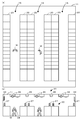
- FIG. 1 is a schematic explanatory diagram of a mounting system 20 and a guidance system 30.
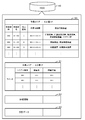
- FIG. FIG. 4 is an explanatory diagram of information stored in a storage device 45. The flowchart showing an example of a guidance process routine. The top view of the work area 11 when the worker M is guided. Explanatory drawing of the work area 11 when the worker M is guided.
- FIG. 1 is a schematic explanatory diagram of the mounting system 20 and the guidance system 30.
- FIG. 2 is a schematic explanatory diagram of the work area 11.
- FIG. 3 is an explanatory diagram of information stored in the storage device 45.
- the mounting system 20 is configured as a board production line, and a plurality of mounting systems 20 are arranged in the work area 11.
- the mounting system 20 includes a printing device 21, a printing inspection device 22, a mounting device 23, a mounting inspection device 24, a reflow device 25, a reflow inspection device 26, a board transfer device, and a management server 28. ing.
- mounting related processing printing processing, mounting processing, reflow processing, substrate transport processing, and various inspection processing performed by these apparatuses
- a device that performs mounting-related processing is referred to as a “mounting-related processing device” and is collectively referred to as “device”.
- the printing device 21, the print inspection device 22, the mounting device 23, the mounting inspection device 24, the reflow device 25, the reflow inspection device 26, and the substrate transport device inform the outside of the state of the processing target product (substrate, component) and the device itself.
- Each has a signal tower 27.
- the signal tower 27 is provided with a plurality of color lamps (for example, green, yellow, red, etc.), and lights in a predetermined mode (lighting, blinking, turning off, etc. for each lighting color) according to the state of the apparatus and processing target. Is done.
- the mounting system 20 includes a device connected to the network 12 and capable of exchanging information such as a device state via the network 12.
- the mounting system 20 also includes a device (for example, a substrate transfer device arranged between the devices) that notifies information such as a device state via the signal tower 27 without being connected to the network 12.
- the printing device 21 is a device that executes a printing process for printing solder on a substrate.
- the printing device 21 applies (prints) the solder to the lower substrate through the pattern hole by pushing the solder into the pattern hole formed in the screen mask using a squeegee.
- the printing device 22 may print a viscous fluid such as a conductive paste or an adhesive.
- the print inspection device 22 is a device that inspects the state of printed solder.
- the print inspection device 22 inspects whether or not the printing state is appropriate based on a captured image obtained by capturing the substrate on which the solder is printed with a camera.
- the mounting device 23 is a device that executes a mounting process for mounting components on a substrate.
- the mounting device 23 arranges (mounts) the components supplied by a supply unit including a feeder on which a tape holding the components is mounted, a tray on which the components are arranged and mounted, and the like on a substrate.
- a mounting head equipped with a suction nozzle, a gripping member, and the like collects components and performs mounting processing by moving on a horizontal plane.
- the mounting inspection device 24 is a device that inspects the mounting state of the components subjected to the mounting process.
- the mounting inspection device 24 inspects whether or not the shape and arrangement position of the component are appropriate based on a captured image obtained by imaging the substrate on which the component is arranged with a camera.
- the reflow device 25 is a device that executes a reflow process of a substrate.
- the reflow device 25 melts the solder by heating the substrate on which the components are arranged on the solder, and then electrically connects and fixes each component on the substrate by cooling.
- the reflow inspection apparatus 26 is an apparatus for inspecting the substrate after reflow.
- the reflow inspection device 26 detects continuity of the reflowed substrate and inspects whether or not the final product is appropriate. When it is determined that the inspection result is not appropriate, the print inspection device 22, the mounting inspection device 24, and the reflow inspection device 26 turn on the lamp of the signal tower 27 in a predetermined manner, for example, blinking the red lamp.
- the substrate transfer device is for transferring a substrate from an upstream device to a downstream device of the production line, and includes a transfer conveyor.
- the substrate transport apparatus may be capable of transporting a substrate by switching between a plurality of lines.
- the management server 28 is a computer that manages information related to implementation.
- the management server 28 stores mounting job information including information such as which parts are arranged at which positions.
- the management server 28 exchanges information with each device of the mounting system 20 connected to the network 12. For example, the printing device 21 outputs the consumption state of the solder, the mounting device 23 outputs the consumption state of the components accommodated in the feeder, and each inspection device outputs the inspection result to the management server 28 via the network 12.
- the management server 28 also receives error information and the like of each device.
- the guidance system 30 is a system that allows an operator to reach an apparatus that requires work in the mounting system 20 during the mounting process.
- the guidance system 30 includes an RFIC device 31, a floor camera 35, a projection device 36, and a guidance server 40.
- the RFIC device 31 is a device that communicates with the IC chip 34 worn by the worker M and detects the current location of the worker M.
- the RFIC device 31 includes a main body 32 and a receiver 33. Connected to the main body 32 are a plurality of receivers 33 arranged in a distributed manner so as to cover the entire area of the work area 11.
- the floor camera 35 images the device in the work area 11 and the worker M, and is configured so that the built-in camera rotates and can capture images in all directions.
- a plurality of floor cameras 35 are arranged on the ceiling surface 18 so as to cover the entire area.
- the floor camera 35 is set to be imaged so as to image the signal tower 27 of a device that is not connected to the network 12.
- the projection device 36 projects an image on any one or more of the devices arranged on the wall surface, floor surface, ceiling surface, and work area 11 of the work area.
- the projection device 36 directly projects an image for guiding the worker M to the device onto the work area 11.
- the projection device 36 acquires image data to be projected on the work area 11 from the guidance server 40.
- the guidance server 40 is a device that guides the movement of the worker M in the work area 11 in which the devices of the mounting system 20 (mounting related processing devices) are arranged.
- the guidance server 40 includes a CPU 42, a ROM 43, a RAM 44, and the like, which controls the entire apparatus, a storage device 45 that stores various application programs and various data files, and a network 12. And a communication unit 46 that performs bidirectional communication with the connected external device.
- the storage device 45 stores correspondence information 50, work area information 51, route information 52, projection data 53, and the like.
- the correspondence information 50 is information that associates a worker with an apparatus that the worker can handle.
- the correspondence information 50 information such as a worker name, a correspondence symbol for distinguishing the worker in the work area 11, the work time zone of the worker, and a device that can be handled are associated with the worker ID.
- the corresponding symbol identifies the worker who should perform the work, and is projected onto the work area when the work occurs in the apparatus.
- the devices that can be assigned may be determined by the arrangement order of the devices, for example, the mounting devices 1 to 5 are the worker A and the mounting devices 6 to 10 are the worker B. An operator having skills that can be eliminated may be determined.
- the correspondence information 50 is associated with the types of work that can be handled by the operator, such as device maintenance work, parts replenishment work, and device abnormality handling work.
- the worker may be classified.
- the guidance server 40 can specify the worker in charge by specifying the work content generated in the mounting system 20.
- the correspondence information 50 may be information in which workers are classified by combinations of work types that can be handled and devices that can be handled.
- the work area information 51 includes production line information arranged in the work area for each work area, such as the serial number of the device included in the production line, the device name, and the work area placement position (for example, XY coordinates). Contains information.
- the route information 52 includes information on the route 15 that is an area of a passage through which the worker M can move in the work area.
- the route information 52 is used when setting the movement route of the worker when the operation of the apparatus occurs.
- the projection data 53 is image data to be projected onto the wall surface 16 and the floor surface 17 of the work area 11.
- the projection data 53 includes, for example, an arrow indicating the moving direction, a corresponding symbol of the worker, an icon image indicating the work content, and the like.
- the guidance server 40 acquires device information that requires work based on an image captured by the network 12 or the floor camera 35. Further, the guidance server 40 acquires the current position of the worker M from the RFIC device 31. Further, the guidance server 40 acquires information on the route 15 that the worker in the work area can move from the route information 52. Then, the guidance server 40 sets the movement path of the worker based on the arrangement position of the apparatus that requires work, the current position of the worker M, and the path of the path information, and the set movement path is sent to the projection device 36. Output.
- the printing device 21 and the mounting device 23 acquire mounting job information from the management server 28.
- the printing device 21 places cream solder on a screen mask and moves a squeegee to form a solder pattern on the substrate.
- the mounting apparatus 23 collects components from the supply unit and arranges them on the substrate.
- the reflow device 25 heats and electrically connects the substrate on which the solder is formed and the component is arranged, and fixes the component to the substrate.
- the print inspection device 22, the mounting inspection device 24, and the reflow inspection device 26 respectively inspect whether or not the processing performed in the previous stage is appropriate. If the processing is not appropriate, the signal tower 27 notifies the result and notifies the result.
- the data is output to the management server 28 via the network 12.
- Each of the mounting systems 20 arranged in the work area 11 executes such processing.
- FIG. 4 is a flowchart illustrating an example of a guidance processing routine executed by the CPU 42 of the guidance server 40.
- This routine is stored in the storage device 45 of the guidance server 40 and is executed during the execution of the production process of the mounting system 20.
- the CPU 42 determines whether or not it is time to acquire the current position of the worker M (step S100).
- This timing can be appropriately set according to the timing at which the worker M does not change much from the previous position and the performance of the system. For example, the timing can be set to 1 minute interval or 5 minute interval.
- the CPU 42 acquires the current position of the worker M regarding which worker M is in the work area 11 from the RFIC device 31 (step S110).
- the RFIC device 31 specifies the position of the worker according to the position of the IC chip 34 and outputs the position information to the guidance server 40.
- the CPU 42 determines whether it is the apparatus state acquisition timing (step S120). This timing can be appropriately set according to the timing at which a change in the apparatus state can be sufficiently detected and the performance of the system. For example, the timing can be set at 1 minute intervals or 5 minute intervals.
- the CPU 42 acquires information on the device state of the devices connected to the network 12 from the management server 28 (step S130). For the devices not connected to the network 12, the CPU 42 causes the floor camera 35 to capture the signal tower 27 of the device, detects the state of the signal tower 27 in the captured image, and acquires the device state (step S140). . In the signal tower 27, since the lamp is turned on or blinks when the apparatus needs work, the CPU 42 can acquire the apparatus state from the captured image.
- the CPU 42 determines whether there is a device that requires work in the mounting system 20 based on the acquired device state (step S150).
- a device that requires work for example, in addition to a device in which an error such as a board conveyance failure or failure has occurred, a device that requires replacement or discharge of a member used in mounting-related processing, for example, replenishment of solder paste is used.
- This includes a printing device 21 that is required, a mounting device 23 that requires replacement of the feeder of the supply unit, and various inspection devices that require discharge of defective substrates.
- the CPU 42 extracts a worker who can take charge of the device that requires work using the correspondence information 50 (step S160), and selects a worker with a short movement route as a charge from among them. (Step S170).
- the CPU 42 selects a worker with a short path length from among them.
- the CPU 42 sets the movement path of the worker based on the arrangement position of the apparatus, the current position of the worker, and the path 15 of the path information 52 (step S180), and projects the set movement path onto the work area. (Step S190).
- the CPU 42 obtains one or more moving route plans that connect the current position of the worker and the arrangement position of the device, which is the target position, from the route 15 included in the route information 52, and selects one of the optimal route plans.
- the CPU 42 may preferentially set a movement route having a shorter route length from the current position of the selected worker to the device requiring the work.
- the CPU 42 is required when the work content requires replacement of a member (for example, a solder container or a feeder) attached to the apparatus or when it is necessary to use a predetermined tool to eliminate the error. It is good also as what sets the movement path
- a member for example, a solder container or a feeder
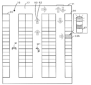
- FIG. 5 is a plan view of the work area 11 when the worker M is guided.
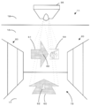
- FIG. 6 is an explanatory diagram of the work area 11 when the worker M is guided.
- the mounting apparatus 23A notifies the management server 28 of the feeder replacement when the remaining number of parts becomes equal to or less than a predetermined value during the mounting process.
- the CPU 42 obtains information from the management server 28 that the feeder replacement of the mounting apparatus 23A is necessary, the CPU 42 selects a worker M1 who can handle the mounting apparatus 23A from the workers in the work area 11, and the worker M1.
- the CPU 42 prepares an image representing the movement path and outputs it to the projection device 36.
- the CPU 42 displays one or more projection devices 36 with movement path images 60 and 61 indicated by arrows indicating movement directions, a display image 62 corresponding to the worker, and a work content image 64 indicating work details. Output to.
- the one or more projection devices 36 arranged in the work area 11 project these images onto the floor surface 17 and the wall surface 16.
- the CPU 42 guides the route so that the worker M1 reaches the warehouse before reaching the mounting apparatus 23A.
- the CPU 42 projects a work content image 64 of the work content on the wall surface 16.
- the worker M1 confirming this can grasp the movement route and the work content, and can reach the mounting apparatus 23A.
- the worker since the worker reaches the mounting apparatus 23A via a warehouse where members necessary for the work are prepared, the work can be performed quickly.
- the worker inputs that the work is completed in the apparatus.
- the management server 28 acquires information indicating that the work has been completed from the device, and outputs the acquired information to the guidance server 40.
- step S190 the CPU 42 determines whether or not work completion information has been acquired from the management server 28 (step S200). If the work completion information has not been acquired, the CPU 42 stands by. On the other hand, when the work completion information is acquired, the CPU 42 ends the output of the movement path (step S210), and ends the projection of the movement accounting image of the projection device 36. Then, after step S210 or when it is not the device state acquisition timing in step S120, the CPU 42 repeatedly executes the processing from step S100. The CPU 42 repeatedly executes such processing until the substrate production processing is completed.
- the control unit 41 of the present embodiment corresponds to an information acquisition unit, a setting unit, and an output unit of the present invention.
- the substrate transfer device corresponds to the mounting-related processing device
- the guide server 40 corresponds to the guide device
- the work area 11 corresponds to the work area
- the projection device 36 corresponds to the display device and the projection device
- the RFIC device 31 It corresponds to an operator recognition device.
- an example of the guidance device of the present invention is also clarified by describing the operation of the guidance system 30.
- the placement position of the mounting related processing device related to the mounting process for mounting the component on the board, the current position of the worker M, and the worker in the work area 11 The movement path of the worker M is set based on the path 15 through which M can move, and the set movement path is output to the projection device 36.
- the projection device 36 projects the movement path as an image in the work area 11. Then, the worker can move to the device where the work has occurred along the movement path projected on the work area 11.
- the worker M can be more easily guided to an apparatus on which work should be performed. And the worker M can work on the apparatus earlier.
- the movement route is projected directly onto the work area, so that the worker M can easily grasp the movement route and go to the device on which the work should be performed.
- the guidance server 40 selects a worker who performs work based on the correspondence information 50 that associates the worker M with devices that the worker M can handle, and sets a movement route according to the selected worker. Therefore, the worker M who can work is guided to the apparatus, and the worker can work on the apparatus more reliably. Furthermore, since the guide server 40 selects an operator having a shorter route length based on the route length between the current position of the worker M and the device on which the work has occurred, the guide server 40 can work on the device earlier. . Furthermore, since the guidance server 40 outputs a movement route that is associated with the worker and includes an image (corresponding symbol) that can be visually recognized by the worker, the worker knows who is performing the work. It is easy to see and can work in the apparatus more reliably.
- the guidance server 40 grasps
- the guidance server 40 projects the movement route onto the floor surface 17, but projects the movement route onto the wall surface, ceiling surface 18, or screen that can be seen from any place in the work area 11. It is good. Even in this way, the worker can move to the device where the work has occurred. It should be noted that any number of movement paths may be projected as long as they are projected onto at least one of the wall surface 16, floor surface 17, ceiling surface 18, and each device.
- the movement path is output to the projection device 36, and the movement path is projected directly onto the work area 11.
- the present invention is not limited to this, and one or two or more arranged in the work area 11 are used. It is good also as what outputs to display apparatuses, such as this display.
- This display device may be, for example, a large display that can be viewed from any location in the work area 11. Even in this way, the worker can move to the device where the work has occurred.
- the guidance server 40 selects the worker using the correspondence information 50.
- the guidance server 40 is not particularly limited thereto, and may be selected without using the correspondence information 50.
- the guidance server 40 is good also as what displays the movement path
- the guidance server 40 can guide an operator to a device that requires work.
- the person in charge can be decided between workers.
- the guidance server 40 selects the person in charge of the work of the apparatus based on the route length of the worker M.
- the present invention is not limited to this, and the route length is considered.
- the person in charge may be selected without doing so.
- the worker M having a short route length can respond quickly, and is preferable.
- the guidance server 40 displays the movement route with an arrow image indicating the movement direction, but the image is not particularly limited to this.
- the guidance server 40 outputs a corresponding symbol as information for specifying the worker, but is not particularly limited thereto.
- a color corresponding to each worker may be set, and the worker may be specified by displaying the movement route in this color.
- the information for identifying the worker can be, for example, one or more of colors, characters, symbols, and images that are visible to the worker.
- the guidance server 40 displays the entire travel route to the device on which the work should be performed, and ends the display of the entire travel route when the work on the device ends.
- the display of the movement route may be sequentially updated as the worker M moves.
- the guidance server 40 may selectively display the moving route to which the worker M moves based on the current position of the worker, instead of displaying the entire moving route.
- the guidance server 40 may display one or two moving path images 60 (arrows) ahead of the current position of the worker M.
- the guidance server 40 may sequentially end the display of the movement route that the worker M has passed based on the current position of the worker M.
- the guidance server 40 selectively displays the movement route to which the worker M has moved as the worker M moves, and sequentially displays the movement route through which the worker M has passed. It may be terminated.
- the guidance server 40 can guide the worker to the device where the work has occurred while suppressing the display of unnecessary travel routes.
- the state of the apparatus is acquired from the network 12 and acquired from an image captured by the floor camera 35, but may be either one. If the guidance server 40 acquires the apparatus state from the network 12, it can be acquired more reliably, and if the apparatus state is acquired from the captured image, standardization is not required.
- the RFIC device 31 grasps the current position of the worker M based on the position of the IC chip 34.
- the present invention is not particularly limited to this.
- the guidance server 40 may perform a face recognition process on the captured image and specify the worker.
- the guidance server 40 can recognize the position of the worker with a simple configuration called an imaging device.
- the work area 11 has been described as having one floor, but the work area may extend over a plurality of floors or may be a part of one floor.
- the management server 28 and the guidance server 40 are provided.
- the present invention is not particularly limited to this, and the management server 28 may have the function of the guidance server 40.
- the guide device of the present invention has been described as the guide server 40.
- the present invention is not particularly limited to this, and a guide method or a program form thereof may be used.
- the present invention can be used in the technical field of mounting components on a board.
Landscapes
- Engineering & Computer Science (AREA)
- Manufacturing & Machinery (AREA)
- Microelectronics & Electronic Packaging (AREA)
- General Engineering & Computer Science (AREA)
- Quality & Reliability (AREA)
- Physics & Mathematics (AREA)
- General Physics & Mathematics (AREA)
- Automation & Control Theory (AREA)
- General Factory Administration (AREA)
- Management, Administration, Business Operations System, And Electronic Commerce (AREA)
- Supply And Installment Of Electrical Components (AREA)
Abstract
案内サーバ(40)は、部品を基板に実装する実装処理に関連する実装関連処理装置の配置位置と、作業者(M)の現在位置と、作業エリア(11)での作業者(M)が移動可能な経路とに基づいて作業者(M)の移動経路を設定し、設定した移動経路を投影装置(36)へ出力する。投影装置(36)は、作業エリア(11)において、画像として移動経路を投影する。そして、作業者は、作業エリア(11)に投影された移動経路に沿って、作業が発生した装置へ移動することができる。
Description
本発明は、案内装置及び案内システムに関する。
従来、生産ラインに関する装置としては、発生した作業の優先度の算定基準として、作業指示立案時の静的条件と、発生作業の内容と、作業者の進捗状況と、作業者の次に予定する作業内容と、作業内容の習熟度とを評価し、優先度を算出する作業管理指示システムが提案されている(例えば、特許文献1参照)。このシステムでは、作業者に効率的に作業指示することで設備効率の低下をなくするとしている。また、生産ラインに関する装置としては、複数の作業領域に分けて作業指示を記憶し、カメラでとらえた作業者の位置に最も近く且つその他の作業員がいない作業領域の作業指示を伝える作業指示装置が提案されている(例えば、特許文献2参照)。この装置では作業遅延が少なくなるとしている。
ところで、部品を基板に実装する実装処理に関連する実装関連処理装置が配列された作業エリアでは、例えば、複数の生産ラインが並ぶことがあり、更に場合によっては、1つの生産ラインの長さが100mなど長くなることがある。このように、生産ラインが長かったり、多数ある場合などには、作業者は、作業を要する装置を見出すことが困難になることもある。しかしながら、特許文献1、2に記載の装置では、作業者が作業を行うべき装置へどのように辿り着くかについては検討されていなかった。このため、実装関連処理装置で作業を執り行うまでに時間を要する場合があった。
本発明は、このような課題に鑑みなされたものであり、作業者が作業を行うべき装置へより容易に誘導することができる案内装置及び案内システムを提供することを主目的とする。
本発明は、上述の主目的を達成するために以下の手段を採った。
本発明の案内装置は、
部品を基板に実装する実装処理に関連する実装関連処理装置が配列された作業エリアでの作業者の移動案内を行う案内装置であって、
作業者による作業が発生した前記実装関連処理装置の装置情報を取得し、作業者の現在位置を少なくとも含む作業者の情報を取得し、前記作業エリアでの作業者が移動可能な経路の情報を少なくとも含む経路情報を取得する情報取得部と、
取得した前記実装関連処理装置の配置位置と、前記作業者の現在位置と、前記経路情報の経路とに基づいて該作業者の移動経路を設定する設定部と、
設定した前記移動経路を前記作業エリアで表示させる表示装置へ出力する出力部と、
を備えたものである。
部品を基板に実装する実装処理に関連する実装関連処理装置が配列された作業エリアでの作業者の移動案内を行う案内装置であって、
作業者による作業が発生した前記実装関連処理装置の装置情報を取得し、作業者の現在位置を少なくとも含む作業者の情報を取得し、前記作業エリアでの作業者が移動可能な経路の情報を少なくとも含む経路情報を取得する情報取得部と、
取得した前記実装関連処理装置の配置位置と、前記作業者の現在位置と、前記経路情報の経路とに基づいて該作業者の移動経路を設定する設定部と、
設定した前記移動経路を前記作業エリアで表示させる表示装置へ出力する出力部と、
を備えたものである。
この装置では、部品を基板に実装する実装処理に関連する実装関連処理装置の配置位置と、作業者の現在位置と、作業エリアでの作業者が移動可能な経路とに基づいて作業者の移動経路を設定し、設定した移動経路を表示装置へ出力する。表示装置では、例えば、作業エリアにおいて、画像として移動経路を表示する。そして、作業者は、作業エリアで表示された移動経路に沿って、作業が発生した実装関連処理装置へ移動することができる。このように、この案内装置では、作業者が作業を行うべき装置へより容易に誘導することができる。そして、作業者は、より早期に実装関連処理装置において作業することができる。
ここで、「実装関連処理装置」としては、例えば、基板を搬送する基板搬送装置、はんだや導電性ペースト、接着剤などの粘性流体を基板に形成する印刷装置や、基板に形成された粘性流体の状態を検査する印刷検査装置、基板上に部品を載置する実装装置、基板に載置された部品の状態を検査する実装検査装置、基板のリフロー処理を実行するリフロー装置、リフロー後の基板を検査するリフロー検査装置などが挙げられる。また、装置での作業としては、例えば、装着された部材の交換作業や、エラーの解除作業などが挙げられる。
本発明の案内装置において、前記表示装置は、前記作業エリアの壁面、床面、天井面及び配列された前記実装関連処理装置のうちいずれか1以上の上に画像を投影する投影装置であり、前記出力部は、前記移動経路を前記投影装置へ出力するものとしてもよい。この案内装置では、移動経路が作業エリアに直接投影されるから、作業者が移動経路を把握しやすく、作業を行うべき装置へ行きやすい。
本発明の案内装置において、前記設定部は、前記作業者と該作業者が担当可能な実装関連処理装置とを対応付けた対応情報に基づいて該実装関連処理装置の作業を行う作業者を選定し、該選定した作業者に応じた移動経路を設定するものとしてもよい。この装置では、作業可能な作業者が実装関連処理装置に導かれるため、作業者は、より確実に実装関連処理装置での作業を行うことができる。
本発明の案内装置において、前記設定部は、前記作業者の現在位置と前記作業が発生した実装関連処理装置との経路長さに基づいて該実装関連処理装置の作業を行う作業者を選定し、該選定した作業者に応じた移動経路を設定するものとしてもよい。この装置では、経路長さに基づいて、実装関連処理装置での作業を行う作業者を選定することができる。この装置において、前記設定部は、より短い前記経路長さの作業者を選定するものとしてもよい。この装置では、より早期に実装関連処理装置での作業を行うことができる。この装置では、実装関連処理装置を担当可能な作業者が複数いる場合には、その中からより短い前記経路長さの作業者を選定するものとしてもよい。この装置では、より早期且つより確実に実装関連処理装置での作業を行うことができる。
本発明の案内装置において、前記出力部は、前記作業者に対応付けられ該作業者が視認可能な色、文字、記号及び画像のうち1以上を含む移動経路を出力するものとしてもよい。この装置では、作業者に対応付けられた情報を含む移動経路が作業エリアで表示されるため、作業者は、作業を行う作業者が誰であるかを視認しやすく、より確実に実装関連処理装置において作業することができる。
本発明の案内装置において、前記情報取得部は、装置状態を示すシグナルタワーを備えた前記実装関連処理装置を撮像する撮像装置が撮像した撮像画像から前記装置情報を取得するものとしてもよい。この装置では、シグナルタワーを撮像することにより実装関連処理装置の状態がわかるため、実装関連処理装置と案内装置との連携が不要であり汎用性が高い。
本発明の案内装置において、前記情報取得部は、前記作業エリアにいる前記作業者を撮像した撮像画像から前記作業者の情報を取得するか、前記作業者が身につけている識別チップから出力される識別子に基づき該作業者の位置を認識する作業者認識装置から前記作業者の情報を取得するものとしてもよい。この装置では、作業者を撮像する場合は、撮像装置という簡単な構成で作業者の位置を認識することができる一方、作業者認識装置を用いる場合は、より確実に作業者の位置を認識することができる。
本発明の案内システムは、
上述したいずれかに記載の案内装置と、
作業者の現在位置を少なくとも含む作業者の情報を認識する作業者認識装置と、
設定した前記移動経路を前記作業エリアで表示させる表示装置と、
を備えたものである。
上述したいずれかに記載の案内装置と、
作業者の現在位置を少なくとも含む作業者の情報を認識する作業者認識装置と、
設定した前記移動経路を前記作業エリアで表示させる表示装置と、
を備えたものである。
この案内システムは、上述した案内装置のいずれかを備えるため、上述した案内装置と同様に、作業者が作業を行うべき装置へより容易に誘導することができる。
本発明の好適な実施形態を図面を参照しながら以下に説明する。図1は、実装システム20及び案内システム30の概略説明図である。図2は、作業エリア11の概略説明図である。図3は、記憶装置45に記憶された情報の説明図である。実装システム20は、基板の生産ラインとして構成され、作業エリア11に複数配設されている。この実装システム20は、印刷装置21と、印刷検査装置22と、実装装置23と、実装検査装置24と、リフロー装置25と、リフロー検査装置26と、基板搬送装置と、管理サーバ28とを備えている。なお、ここでは、これらの装置が行う、印刷処理、実装処理、リフロー処理、基板の搬送処理、及び各種検査処理を「実装関連処理」と称する。また、実装関連処理を行う装置を「実装関連処理装置」とし、「装置」と総称する。印刷装置21や印刷検査装置22、実装装置23、実装検査装置24、リフロー装置25、リフロー検査装置26及び基板搬送装置は、処理対象品(基板、部品)や装置自体の状態を外部に報知するシグナルタワー27をそれぞれが備えている。シグナルタワー27は、複数色のランプ(例えば、緑、黄色、赤など)を備えており、装置や処理対象の状態に応じて所定の態様(点灯色ごとの点灯、点滅、消灯など)で点灯される。実装システム20は、ネットワーク12に接続されこれを介して装置状態などの情報をやりとりできる装置を備える。また、実装システム20は、ネットワーク12に接続されずシグナルタワー27を介して装置状態などの情報を報知する装置(例えば、各装置間に配置された基板搬送装置など)も備える。
印刷装置21は、基板上にはんだを印刷する印刷処理を実行する装置である。印刷装置21は、スキージを用いてスクリーンマスクに形成されたパターン孔にはんだを押し込むことによりそのパターン孔を介して下方の基板にはんだを塗布(印刷)する。なお印刷装置22は、導電ペースト、接着剤などの粘性流体を印刷するものとしてもよい。印刷検査装置22は、印刷されたはんだの状態を検査する装置である。印刷検査装置22は、はんだが印刷された基板をカメラにより撮像した撮像画像に基づいて印刷状態が適正であるか否かを検査する。実装装置23は、部品を基板上に実装する実装処理を実行する装置である。実装装置23は、部品が保持されたテープを装着したフィーダや部品が配列載置されたトレイなどを備えた供給ユニットにより供給された部品を基板上の所定位置に配置(実装)する。実装装置23は、吸着ノズルや把持部材などを装着した実装ヘッドが部品を採取し、水平平面上を移動することにより実装処理を行う。実装検査装置24は、実装処理された部品の実装状態を検査する装置である。実装検査装置24は、部品が配置された基板をカメラにより撮像した撮像画像に基づいて部品の形状や配置位置が適正であるか否かを検査する。リフロー装置25は、基板のリフロー処理を実行する装置である。リフロー装置25は、はんだ上に部品が配置された基板を加熱することによりはんだを溶融し、その後冷却することにより各部品を基板上に電気的に接続及び固定する。リフロー検査装置26は、リフロー後の基板を検査する装置である。リフロー検査装置26は、リフローされた基板の導通などを検出し最終製品として適正であるか否かを検査する。印刷検査装置22や実装検査装置24、リフロー検査装置26は、検査結果が適正でないと判定されると、シグナルタワー27のランプを所定の態様、例えば、赤ランプを点滅など灯する。基板搬送装置は、図示しないが、生産ラインの上流側の装置から下流側の装置へ基板の搬送を行うものであり、搬送コンベアを備える。この基板搬送装置は、複数のライン間で切り替えて基板を搬送可能なものとしてもよい。
管理サーバ28は、実装に関連する情報を管理するコンピュータである。管理サーバ28は、どの位置にどの部品を配置するかなどの情報を含む実装ジョブ情報を記憶している。管理サーバ28は、ネットワーク12に接続されている実装システム20の各装置と情報のやりとりを行う。例えば、印刷装置21は、はんだの消費状態、実装装置23はフィーダに収容された部品の消費状態、各検査装置は検査結果などをネットワーク12を介して管理サーバ28へ出力する。また、管理サーバ28は、各装置のエラー情報なども受信する。
案内システム30は、実装処理時において実装システム20での作業を要する装置へ作業者を到達させるシステムである。案内システム30は、RFIC装置31と、フロアカメラ35と、投影装置36と、案内サーバ40とを備えている。RFIC装置31は、作業者Mが身につけているICチップ34と通信しその作業者Mに現在地を検出する装置である。このRFIC装置31は、本体32と、受信機33とを備えている。本体32には、作業エリア11の全領域をカバーできるように分散して配置された複数の受信機33が接続されている。フロアカメラ35は、作業エリア11の装置や作業者Mを撮像するものであり、内蔵したカメラが回転し、全方位の画像を撮像できるよう構成されている。また、作業エリア11には、その全領域をカバーできるよう複数のフロアカメラ35が天井面18に配設されている。フロアカメラ35は、ネットワーク12に接続されていない装置のシグナルタワー27を撮像するよう撮像対象が設定されている。投影装置36は、作業エリアの壁面、床面、天井面及び作業エリア11に配列された各装置のうちいずれか1以上の上に画像を投影するものである。この投影装置36は、作業者Mを装置へ誘導する画像を作業エリア11に直接投影する。投影装置36は、作業エリア11に投影する画像データを案内サーバ40から取得する。
案内サーバ40は、実装システム20の装置(実装関連処理装置)が配列された作業エリア11での作業者Mの移動案内を行う装置である。案内サーバ40は、図1に示すように、CPU42、ROM43及びRAM44などにより構成され装置全体の制御を司る制御部41と、各種アプリケーションプログラムや各種データファイルを記憶する記憶装置45と、ネットワーク12に接続された外部機器と双方向の通信を行う通信部46とを備える。記憶装置45は、図3に示すように、対応情報50、作業エリア情報51、経路情報52及び投影データ53などを記憶する。対応情報50は、作業者とその作業者が担当可能な装置とを対応付けた情報である。この対応情報50では、作業者名、作業エリア11での作業者を区別する対応記号、作業者の作業時間帯、担当可能な装置などの情報が作業者IDに対応付けられている。対応記号は、作業を行うべき作業者を特定するものであり、装置に作業が発生したときに、作業エリアに投影される。ここでは、投影された対応記号に対応付けられた作業者がその作業を行うよう定められている。担当可能な装置は、例えば、実装装置の1~5を作業者A、実装装置の6~10を作業者Bのように、装置の並び順で作業者が定められてもよいし、トラブルを解消できる技能を有する作業者が定められてもよい。あるいは、対応情報50は、例えば、装置のメンテナンス作業、部品の補給作業、装置異常の対処作業など、作業者が担当可能な作業の種類と作業者とが対応付けられており、作業の種類で作業者が区分されているものとしてもよい。この場合、案内サーバ40は、実装システム20で生じた作業内容を特定することにより、担当する作業者を特定することができる。なお、対応情報50は、担当可能な作業の種類と担当可能な装置との組み合わせで作業者が区分されているものとしてもよい。作業エリア情報51は、作業エリアに配置された生産ラインの情報が作業エリアごとに含まれ、その生産ラインに含まれる装置のシリアル番号、装置名及び作業エリアの配置位置(例えばXY座標)などの情報を含む。経路情報52は、作業エリアでの作業者Mが移動可能な通路の領域である経路15の情報を含む。経路情報52は、装置の作業発生時に、作業者の移動経路を設定する際に用いられる。投影データ53は、作業エリア11の壁面16や床面17に投影する画像のデータである。投影データ53には、例えば、移動方向を表す矢印や、作業者の対応記号、作業内容を表すアイコン画像などが含まれる。この案内サーバ40は、ネットワーク12又はフロアカメラ35で撮像した画像に基づいて作業を要する装置情報を取得する。また、案内サーバ40は、RFIC装置31から、作業者Mの現在位置を取得する。また、案内サーバ40は、経路情報52から作業エリアでの作業者が移動可能な経路15の情報を取得する。そして、案内サーバ40は、作業を要する装置の配置位置と、作業者Mの現在位置と、経路情報の経路とに基づいて作業者の移動経路を設定し、設定した移動経路を投影装置36へ出力する。
次に、こうして構成された本実施形態の実装システム20の動作について説明する。実装システム20での基板の生産が開始されると、印刷装置21や実装装置23は、管理サーバ28から実装ジョブ情報を取得する。印刷装置21は、スクリーンマスクにクリームはんだを載せ、スキージを移動させて基板上にはんだパターンを形成する。実装装置23は、供給ユニットから部品を採取して基板上に配置する。リフロー装置25は、はんだが形成され部品が配置された基板を加熱し、電気的に接続すると共に基板に部品を固定させる。印刷検査装置22、実装検査装置24及びリフロー検査装置26は、その前段階で行われた処理が適切であったかについて各々検査し、処理が適切でない場合は、シグナルタワー27で報知すると共にその結果を管理サーバ28へネットワーク12を介して出力する。このような処理を、作業エリア11に配置された実装システム20のそれぞれが実行する。
次に、実装システム20の生産処理中に実行される案内システム30の動作について説明する。図4は、案内サーバ40のCPU42が実行する案内処理ルーチンの一例を表すフローチャートである。このルーチンは、案内サーバ40の記憶装置45に記憶され、実装システム20の生産処理の実行中に実行される。このルーチンを開始すると、まず、CPU42は、作業者Mの現在位置を取得するタイミングであるか否かを判定する(ステップS100)。このタイミングは、作業者Mが前回の位置から余り変わらないようなタイミングや、システムの性能に応じて適宜設定することができ、例えば、1分間隔や5分間隔とすることができる。作業者の現在位置を取得するタイミングであるときには、CPU42は、作業エリア11のどこにどの作業者Mがいるかについての作業者Mの現在位置をRFIC装置31から取得する(ステップS110)。RFIC装置31は、ICチップ34がどの位置にあるかによって作業者の位置を特定し、その位置情報を案内サーバ40へ出力する。
ステップS110のあと、又はステップS100で作業者の位置取得タイミングでないときには、CPU42は、装置状態の取得タイミングであるか否かを判定する(ステップS120)。このタイミングは、装置状態の変化を十分検出できるようなタイミングや、システムの性能に応じて適宜設定することができ、例えば、1分間隔や5分間隔とすることができる。装置状態の取得タイミングであるときには、CPU42は、ネットワーク12に接続された機器についてはその装置状態の情報を管理サーバ28から取得する(ステップS130)。また、CPU42は、ネットワーク12に接続されていない装置については、フロアカメラ35に装置のシグナルタワー27を撮像させ、撮像画像のシグナルタワー27の状態を検出して装置状態を取得する(ステップS140)。シグナルタワー27は、装置に作業を要する際にランプが点灯又は点滅することから、CPU42は、撮像画像によって、装置状態を取得することができる。
次に、CPU42は、取得した装置状態に基づいて、作業を要する装置が実装システム20にあるか否かを判定する(ステップS150)。ここで、「作業を要する装置」としては、例えば、基板の搬送不良や故障などエラーが生じた装置のほか、実装関連処理で用いる部材の交換や排出を要する装置、例えば、はんだペーストの補充を要する印刷装置21や、供給ユニットのフィーダの交換を要する実装装置23、不良基板の排出を要する各検査装置などが含まれる。作業を要する装置があるときには、CPU42は、作業を要する装置を担当可能である作業者を対応情報50を用いて抽出し(ステップS160)、その中から移動経路の短い作業者を担当に選定する(ステップS170)。ここでは、例えば、作業を要する装置を担当可能である作業者が複数いる場合には、CPU42は、その中から経路長さの短い作業者を担当に選定するものとする。
続いて、CPU42は、装置の配置位置、作業者の現在位置及び経路情報52の経路15に基づいて、作業者の移動経路を設定し(ステップS180)、設定した移動経路を作業エリアに投影させる(ステップS190)。CPU42は、作業者の現在位置と目的位置である装置の配置位置とを結ぶ1以上の移動経路案を経路情報52に含まれる経路15から求め、このうち最適な1つの経路案を選択することにより移動経路を設定する。CPU42は、選定された作業者の現在位置から作業を要する装置までの経路長さがより短い移動経路を優先的に設定するものとしてもよい。また、作業内容が装置に装着される部材(例えば、はんだ容器やフィーダなど)の交換を要する場合や、エラーの解消に所定の工具の使用を要する場合などには、CPU42は、必要とされる部材の収容場所を経由した移動経路を設定するものとしてもよい。更に、CPU42は、移動経路案の中に現在作業中である装置の前を通る経路が含まれている場合は、その移動経路案の優先順位をより下げて移動経路を設定するものとしてもよい。作業中の装置前は通過しにくい場合があるからである。また、CPU42は、作業エリア11に投影する移動経路に作業者Mを特定する情報(例えば対応記号)や作業内容を表すアイコン画像や文字、記号などを含めるものとしてもよい。
図5は、作業者Mが案内される際の作業エリア11の平面図である。図6は、作業者Mが案内される際の作業エリア11の説明図である。ここでは、実装装置23Aがフィーダの交換を要するものとし、対応記号「1」の作業者M1が実装装置23Aを担当可能に定められている場合を具体例として説明する。実装装置23Aは、実装処理を実行中に、部品の残数が所定以下になるとフィーダ交換を管理サーバ28へ通知する。CPU42は、実装装置23Aのフィーダ交換を要する旨の情報を管理サーバ28から取得すると、作業エリア11にいる作業者の中から、実装装置23Aを担当可能な作業者M1を選定し、作業者M1を実装装置23Aまで誘導する移動経路を設定する。このとき、新たなフィーダが用意されている倉庫を経由する移動経路を設定する。続いて、CPU42は、移動経路を表す画像を用意し、投影装置36へ出力する。図5,6に示すように、CPU42は、移動方向を示す矢印の移動経路画像60,61や作業者に対応する担当表示画像62、作業内容を示す作業内容画像64を1以上の投影装置36に出力する。作業エリア11に配置された1以上の投影装置36は、これらの画像を床面17や壁面16に投影させる。図5に示すように、CPU42は、作業者M1が実装装置23Aに辿り着く前に倉庫に行くよう経路案内を行わせる。また、図6に示すように、CPU42は、作業内容の作業内容画像64を壁面16に投影させる。これを確認した作業者M1は、その移動経路や作業内容を把握し、実装装置23Aに到達することができる。また、作業者は、作業に必要な部材が用意されている倉庫を介して実装装置23Aに至るので、迅速に作業を行うことができる。そして、作業者は、作業完了後に、その装置において作業を完了した旨の入力を行う。管理サーバ28は、作業が完了した旨の情報をその装置から取得し、取得した情報を案内サーバ40へ出力する。
さて、ステップS190のあと、CPU42は、管理サーバ28から作業完了の情報を取得したか否かを判定し(ステップS200)、作業完了の情報を取得していないときには、そのまま待機する。一方、作業完了の情報を取得したときには、CPU42は、移動経路の出力を終了し(ステップS210)、投影装置36の移動経理画像の投影を終了させる。そして、CPU42は、ステップS210のあと、又は、ステップS120で装置状態の取得タイミングでないときには、ステップS100以降の処理を繰り返し実行する。CPU42は、このような処理を、基板の生産処理が終了するまで、繰り返し実行するのである。
ここで、本実施形態の構成要素と本発明の構成要素との対応関係を明らかにする。本実施形態の制御部41が本発明の情報取得部、設定部及び出力部に相当し、印刷装置21、印刷検査装置22、実装装置23、実装検査装置24、リフロー装置25、リフロー検査装置26及び基板搬送装置が実装関連処理装置に相当し、案内サーバ40が案内装置に相当し、作業エリア11が作業エリアに相当し、投影装置36が表示装置及び投影装置に相当し、RFIC装置31が作業者認識装置に相当する。なお、本実施形態では、案内システム30の動作を説明することにより本発明の案内装置の一例も明らかにしている。
以上説明した第1実施形態の案内サーバ40によれば、部品を基板に実装する実装処理に関連する実装関連処理装置の配置位置と、作業者Mの現在位置と、作業エリア11での作業者Mが移動可能な経路15とに基づいて作業者Mの移動経路を設定し、設定した移動経路を投影装置36へ出力する。投影装置36は、作業エリア11において、画像として移動経路を投影する。そして、作業者は、作業エリア11に投影された移動経路に沿って、作業が発生した装置へ移動することができる。このように、この案内サーバ40では、作業者Mが作業を行うべき装置へより容易に誘導することができる。そして、作業者Mは、より早期に装置において作業することができる。また、案内サーバ40では、移動経路が作業エリアに直接投影されるから、作業者Mが移動経路を把握しやすく、作業を行うべき装置へ行きやすい。
また、案内サーバ40では、作業者Mと作業者Mが担当可能な装置とを対応付けた対応情報50に基づいて作業を行う作業者を選定し、選定した作業者に応じた移動経路を設定するため、作業可能な作業者Mが装置に導かれ、作業者は、より確実に装置での作業を行うことができる。更に、案内サーバ40では、作業者Mの現在位置と作業が発生した装置との経路長さに基づき、より短い経路長さの作業者を選定するため、より早期に装置において作業することができる。更にまた、案内サーバ40では、作業者に対応付けられ、作業者が視認可能な画像(対応記号)を含む移動経路を出力するため、作業者は、作業を行う作業者が誰であるかを視認しやすく、より確実に装置において作業することができる。そして、案内サーバ40は、シグナルタワーを撮像した画像に基づいてその装置の状態を把握するため、実装関連処理装置と案内サーバ40との連携が不要であり汎用性が高い。
そしてまた、案内サーバ40は、作業者が身につけているICチップ34(識別チップ)から出力される識別子に基づき作業者の位置を認識するRFIC装置31から作業者の位置情報を取得するため、より確実に作業者の位置を認識することができる。
そしてまた、案内サーバ40は、作業者が身につけているICチップ34(識別チップ)から出力される識別子に基づき作業者の位置を認識するRFIC装置31から作業者の位置情報を取得するため、より確実に作業者の位置を認識することができる。
なお、本発明は上述した実施形態に何ら限定されることはなく、本発明の技術的範囲に属する限り種々の態様で実施し得ることはいうまでもない。
例えば、上述した実施形態では、案内サーバ40は、移動経路を床面17に投影するものとしたが、作業エリア11のどの場所からでも見える壁面や天井面18、スクリーンに移動経路を投影するものとしてもよい。こうしても、作業者は、作業が発生した装置へ移動することができる。なお、移動経路は、壁面16、床面17、天井面18及び各装置のうち少なくとも1以上に投影するものとすれば、どこに、いくつ投影されてもよい。
上述した実施形態では、移動経路を投影装置36へ出力し、作業エリア11に直接移動経路を投影するものとしたが特にこれに限定されず、作業エリア11に配設された、1又は2以上のディスプレイなどの表示装置に出力するものとしてもよい。この表示装置は、例えば、作業エリア11のどの場所からでも見ることができる大型ディスプレイとしてもよい。こうしても、作業者は、作業が発生した装置へ移動することができる。
上述した実施形態では、案内サーバ40は、対応情報50を用いて作業者を選定するものとしたが、特にこれに限定されず、対応情報50を用いずに選定するものとしてもよい。あるいは、案内サーバ40は、作業者を選定せずに作業を行うべき装置までの移動経路を表示するものとしてもよい。この案内サーバ40では、作業を要する装置まで、作業者を誘導することはできる。なお、作業者同士で担当者を決めることができる。
上述した実施形態では、案内サーバ40は、作業者Mの経路長さに基づいて、装置の作業を担当する担当者を選定するものとしたが、特にこれに限定されず、経路長さを考慮せずに担当者を選定してもよい。但し、経路長さが短い作業者Mの方が迅速に対応することができ、好ましい。
上述した実施形態では、案内サーバ40は、移動方向を表す矢印の画像で移動経路を表示するものとしたが、特に画像はこれに限定されない。また、上述した実施形態では、案内サーバ40は、作業者を特定する情報として、対応記号を出力するものとしたが、特にこれに限定されない。例えば、各々の作業者に対応する色を設定しておき、移動経路をこの色で表示することにより、作業者を特定するものとしてもよい。この案内サーバ40においても、作業を行う作業者が誰であるかを視認しやすい。作業者を特定する情報は、例えば、作業者が視認可能な色、文字、記号及び画像のうち1以上とすることができる。
上述した実施形態では、案内サーバ40は、作業を行うべき装置までの移動経路の全体を表示させ、装置での作業が終了すると移動経路の全体の表示を終了するものとしたが、特にこれに限定されず、例えば作業者Mの移動に伴い、移動経路の表示を順次更新するものとしてもよい。例えば、案内サーバ40は、移動経路の全体を表示するのに代えて、作業者の現在位置に基づいて作業者Mの移動する先の移動経路を選択的に表示するものとしてもよい。このとき、案内サーバ40は、例えば、作業者Mの現在位置から1つ又は2つ先の移動経路画像60(矢印)を表示するものとしてもよい。また、案内サーバ40は、作業者Mの現在位置に基づいて、作業者Mが通過した移動経路を順次、表示終了するものとしてもよい。更に、これらの組合せにより、案内サーバ40は、作業者Mの移動に伴い、作業者Mの移動する先の移動経路を選択的に表示すると共に、作業者Mが通過した移動経路を順次、表示終了するものとしてもよい。この案内サーバ40では、不要な移動経路の表示を抑制しつつ、作業が発生した装置へ作業者を誘導することができる。
上述した実施形態では、装置の状態をネットワーク12から取得すると共に、フロアカメラ35での撮像画像から取得するとしたが、いずれか一方としてもよい。案内サーバ40がネットワーク12から装置状態を取得するものとすればより確実に取得できるし、撮像画像から装置状態を取得するものとすれば規格の統一が不要である。
上述した実施形態では、RFIC装置31がICチップ34の位置に基づいて作業者Mの現在位置を把握するものとしたが、特にこれに限定されず、例えば、フロアカメラ35で撮像した画像に対して人認識処理を行うことで作業者Mの現在位置を把握するものとしてもよい。このとき、案内サーバ40は、撮像画像に対して、顔認識処理を行い、作業者の特定まで行うものとしてもよい。この案内サーバ40では、撮像装置という簡単な構成で作業者の位置を認識することができる。
上述した実施形態では、作業エリア11が1フロアからなるものとして説明したが、作業エリアは複数のフロアに亘っているものとしてもよいし、1フロアのうち一部であるものとしてもよい。
上述した実施形態では、管理サーバ28と案内サーバ40とを備えるものとしたが、特にこれに限定されず、管理サーバ28が案内サーバ40の機能を有するものとしてもよい。
上述した実施形態では、本発明の案内装置を案内サーバ40として説明したが、特にこれに限定されず、案内方法やそのプログラムの形態としてもよい。
本発明は、基板に部品を実装する技術分野に利用可能である。
11 作業エリア、12 ネットワーク、15 経路、16 壁面、17 床面、18 天井面、20 実装システム、21 印刷装置、22 印刷検査装置、23,23A 実装装置、24 実装検査装置、25 リフロー装置、27 シグナルタワー、28 管理サーバ、30 案内システム、31 RFIC装置、32 本体、33 受信機、34 ICチップ、35 フロアカメラ、36 投影装置、40 案内サーバ、41 制御部、42 CPU、43 ROM、45 記憶装置、46 ディスプレイ、47 入力装置、48 通信部、50 対応情報、51 作業エリア情報、52 経路情報、53 投影データ、60 移動経路画像、61 移動経路画像、62 担当表示画像、64 作業内容画像、M,M1 作業者。
Claims (8)
- 部品を基板に実装する実装処理に関連する実装関連処理装置が配列された作業エリアでの作業者の移動案内を行う案内装置であって、
作業者による
作業が発生した前記実装関連処理装置の装置情報を取得し、作業者の現在位置を少なくとも含む作業者の情報を取得し、前記作業エリアでの作業者が移動可能な経路の情報を少なくとも含む経路情報を取得する情報取得部と、
取得した前記実装関連処理装置の配置位置と、前記作業者の現在位置と、前記経路情報の経路とに基づいて該作業者の移動経路を設定する設定部と、
設定した前記移動経路を前記作業エリアで表示させる表示装置へ出力する出力部と、
を備えた案内装置。 - 前記表示装置は、前記作業エリアの壁面、床面、天井面及び配列された前記実装関連処理装置のうちいずれか1以上の上に画像を投影する投影装置であり、
前記出力部は、前記移動経路を前記投影装置へ出力する、請求項1に記載の案内装置。 - 前記設定部は、前記作業者と該作業者が担当可能な実装関連処理装置とを対応付けた対応情報に基づいて該実装関連処理装置の作業を行う作業者を選定し、該選定した作業者に応じた移動経路を設定する、請求項1又は2に記載の案内装置。
- 前記設定部は、前記作業者の現在位置と前記作業が発生した実装関連処理装置との経路長さに基づいて該実装関連処理装置の作業を行う作業者を選定し、該選定した作業者に応じた移動経路を設定する、請求項1~3のいずれか1項に記載の案内装置。
- 前記出力部は、前記作業者に対応付けられ該作業者が視認可能な色、文字、記号及び画像のうち1以上を含む移動経路を出力する、請求項1~4のいずれか1項に記載の案内装置。
- 前記情報取得部は、装置状態を示すシグナルタワーを備えた前記実装関連処理装置を撮像する撮像装置が撮像した撮像画像から前記装置情報を取得する、請求項1~5のいずれか1項に記載の案内装置。
- 前記情報取得部は、前記作業エリアにいる前記作業者を撮像した撮像画像から前記作業者の情報を取得するか、前記作業者が身につけている識別チップから出力される識別子に基づき該作業者の位置を認識する作業者認識装置から前記作業者の情報を取得する、請求項1~6のいずれか1項に記載の案内装置。
- 請求項1~7のいずれか1項に記載の案内装置と、
作業者の現在位置を少なくとも含む作業者の情報を認識する作業者認識装置と、
設定した前記移動経路を前記作業エリアで表示させる表示装置と、
を備えた案内システム。
Priority Applications (2)
| Application Number | Priority Date | Filing Date | Title |
|---|---|---|---|
| JP2017524290A JP6622801B2 (ja) | 2015-06-22 | 2015-06-22 | 案内装置及び案内システム |
| PCT/JP2015/067874 WO2016207948A1 (ja) | 2015-06-22 | 2015-06-22 | 案内装置及び案内システム |
Applications Claiming Priority (1)
| Application Number | Priority Date | Filing Date | Title |
|---|---|---|---|
| PCT/JP2015/067874 WO2016207948A1 (ja) | 2015-06-22 | 2015-06-22 | 案内装置及び案内システム |
Publications (1)
| Publication Number | Publication Date |
|---|---|
| WO2016207948A1 true WO2016207948A1 (ja) | 2016-12-29 |
Family
ID=57585215
Family Applications (1)
| Application Number | Title | Priority Date | Filing Date |
|---|---|---|---|
| PCT/JP2015/067874 Ceased WO2016207948A1 (ja) | 2015-06-22 | 2015-06-22 | 案内装置及び案内システム |
Country Status (2)
| Country | Link |
|---|---|
| JP (1) | JP6622801B2 (ja) |
| WO (1) | WO2016207948A1 (ja) |
Cited By (11)
| Publication number | Priority date | Publication date | Assignee | Title |
|---|---|---|---|---|
| JP2018112940A (ja) * | 2017-01-12 | 2018-07-19 | 富士通株式会社 | 作業者割当て装置、作業者割当て方法及び作業者割当てプログラム |
| JP2018142186A (ja) * | 2017-02-28 | 2018-09-13 | パナソニックIpマネジメント株式会社 | 作業指示システムおよび作業指示方法 |
| JP2018142187A (ja) * | 2017-02-28 | 2018-09-13 | パナソニックIpマネジメント株式会社 | 作業指示システムおよび作業指示方法 |
| WO2019188989A1 (ja) * | 2018-03-29 | 2019-10-03 | 日本電気株式会社 | 案内制御装置および案内制御方法 |
| WO2020170489A1 (ja) * | 2019-02-19 | 2020-08-27 | パナソニックIpマネジメント株式会社 | 無人飛行体、情報処理方法およびプログラム |
| CN111758309A (zh) * | 2018-04-05 | 2020-10-09 | 株式会社富士 | 信息处理装置及信息处理方法 |
| JP2020181525A (ja) * | 2019-04-26 | 2020-11-05 | 清水建設株式会社 | 受付案内システム、受付案内方法 |
| JP2021034957A (ja) * | 2019-08-28 | 2021-03-01 | パナソニックIpマネジメント株式会社 | 投影システム及び投影方法 |
| JP2022091838A (ja) * | 2017-01-10 | 2022-06-21 | 株式会社Fuji | 実装システム及びエラー対処方法 |
| WO2025104852A1 (ja) * | 2023-11-15 | 2025-05-22 | 株式会社Fuji | 生産管理方法および生産管理システム |
| EP4582908A1 (de) | 2024-01-04 | 2025-07-09 | KRONES Aktiengesellschaft | Bedienunterstützungssystem für einen anwender einer behälterbehandlungsanlage |
Citations (7)
| Publication number | Priority date | Publication date | Assignee | Title |
|---|---|---|---|---|
| JPH09130877A (ja) * | 1995-11-02 | 1997-05-16 | Omron Corp | 設備故障通報装置 |
| JPH11258380A (ja) * | 1998-03-13 | 1999-09-24 | Mitsubishi Heavy Ind Ltd | プラント保守作業支援装置 |
| JP2002132324A (ja) * | 2000-10-23 | 2002-05-10 | Mitsubishi Electric Corp | 稼働状態確認装置及び稼働状態確認方法 |
| JP2003046659A (ja) * | 2001-08-02 | 2003-02-14 | Mitsubishi Heavy Ind Ltd | 遠隔監視制御装置及び遠隔監視制御方法 |
| JP2004093358A (ja) * | 2002-08-30 | 2004-03-25 | Matsushita Electric Ind Co Ltd | 携帯端末及び携帯端末により実行可能なプログラム並びにナビゲーションシステム |
| JP2005183572A (ja) * | 2003-12-18 | 2005-07-07 | Matsushita Electric Ind Co Ltd | 電子部品装着装置、スクリーン印刷装置、リフロー装置および電子部品実装システム、並びに、電子部品装着方法、スクリーン印刷方法およびリフロー方法 |
| JP2007188467A (ja) * | 2005-12-12 | 2007-07-26 | Nissan Motor Co Ltd | 作業指示装置および作業指示方法 |
Family Cites Families (1)
| Publication number | Priority date | Publication date | Assignee | Title |
|---|---|---|---|---|
| US20080007400A1 (en) * | 2006-07-07 | 2008-01-10 | Terry Murphy | Image projection system |
-
2015
- 2015-06-22 WO PCT/JP2015/067874 patent/WO2016207948A1/ja not_active Ceased
- 2015-06-22 JP JP2017524290A patent/JP6622801B2/ja active Active
Patent Citations (7)
| Publication number | Priority date | Publication date | Assignee | Title |
|---|---|---|---|---|
| JPH09130877A (ja) * | 1995-11-02 | 1997-05-16 | Omron Corp | 設備故障通報装置 |
| JPH11258380A (ja) * | 1998-03-13 | 1999-09-24 | Mitsubishi Heavy Ind Ltd | プラント保守作業支援装置 |
| JP2002132324A (ja) * | 2000-10-23 | 2002-05-10 | Mitsubishi Electric Corp | 稼働状態確認装置及び稼働状態確認方法 |
| JP2003046659A (ja) * | 2001-08-02 | 2003-02-14 | Mitsubishi Heavy Ind Ltd | 遠隔監視制御装置及び遠隔監視制御方法 |
| JP2004093358A (ja) * | 2002-08-30 | 2004-03-25 | Matsushita Electric Ind Co Ltd | 携帯端末及び携帯端末により実行可能なプログラム並びにナビゲーションシステム |
| JP2005183572A (ja) * | 2003-12-18 | 2005-07-07 | Matsushita Electric Ind Co Ltd | 電子部品装着装置、スクリーン印刷装置、リフロー装置および電子部品実装システム、並びに、電子部品装着方法、スクリーン印刷方法およびリフロー方法 |
| JP2007188467A (ja) * | 2005-12-12 | 2007-07-26 | Nissan Motor Co Ltd | 作業指示装置および作業指示方法 |
Cited By (18)
| Publication number | Priority date | Publication date | Assignee | Title |
|---|---|---|---|---|
| JP7179211B2 (ja) | 2017-01-10 | 2022-11-28 | 株式会社Fuji | 実装システム及びエラー対処方法 |
| JP2022091838A (ja) * | 2017-01-10 | 2022-06-21 | 株式会社Fuji | 実装システム及びエラー対処方法 |
| JP2018112940A (ja) * | 2017-01-12 | 2018-07-19 | 富士通株式会社 | 作業者割当て装置、作業者割当て方法及び作業者割当てプログラム |
| JP2018142186A (ja) * | 2017-02-28 | 2018-09-13 | パナソニックIpマネジメント株式会社 | 作業指示システムおよび作業指示方法 |
| JP2018142187A (ja) * | 2017-02-28 | 2018-09-13 | パナソニックIpマネジメント株式会社 | 作業指示システムおよび作業指示方法 |
| JP7107364B2 (ja) | 2018-03-29 | 2022-07-27 | 日本電気株式会社 | 案内制御装置および案内制御方法、案内制御システム、プログラム |
| WO2019188989A1 (ja) * | 2018-03-29 | 2019-10-03 | 日本電気株式会社 | 案内制御装置および案内制御方法 |
| US11959768B2 (en) | 2018-03-29 | 2024-04-16 | Nec Corporation | Guidance control device and guidance control method |
| JPWO2019188989A1 (ja) * | 2018-03-29 | 2021-03-11 | 日本電気株式会社 | 案内制御装置および案内制御方法、案内制御システム、プログラム |
| CN111758309A (zh) * | 2018-04-05 | 2020-10-09 | 株式会社富士 | 信息处理装置及信息处理方法 |
| WO2020170489A1 (ja) * | 2019-02-19 | 2020-08-27 | パナソニックIpマネジメント株式会社 | 無人飛行体、情報処理方法およびプログラム |
| JP7409782B2 (ja) | 2019-04-26 | 2024-01-09 | 清水建設株式会社 | 受付案内システム、受付案内方法 |
| JP2020181525A (ja) * | 2019-04-26 | 2020-11-05 | 清水建設株式会社 | 受付案内システム、受付案内方法 |
| JP2021034957A (ja) * | 2019-08-28 | 2021-03-01 | パナソニックIpマネジメント株式会社 | 投影システム及び投影方法 |
| JP7417838B2 (ja) | 2019-08-28 | 2024-01-19 | パナソニックIpマネジメント株式会社 | 投影システム及び投影方法 |
| WO2025104852A1 (ja) * | 2023-11-15 | 2025-05-22 | 株式会社Fuji | 生産管理方法および生産管理システム |
| EP4582908A1 (de) | 2024-01-04 | 2025-07-09 | KRONES Aktiengesellschaft | Bedienunterstützungssystem für einen anwender einer behälterbehandlungsanlage |
| DE102024100207A1 (de) * | 2024-01-04 | 2025-07-10 | Krones Aktiengesellschaft | Bedienunterstützungssystem für einen Anwender einer Behälterbehandlungsanlage |
Also Published As
| Publication number | Publication date |
|---|---|
| JP6622801B2 (ja) | 2019-12-18 |
| JPWO2016207948A1 (ja) | 2018-04-05 |
Similar Documents
| Publication | Publication Date | Title |
|---|---|---|
| JP6622801B2 (ja) | 案内装置及び案内システム | |
| JP7044935B2 (ja) | 実装システム、管理装置及びエラー対処方法 | |
| US8849442B2 (en) | Component mounting line and component mounting method | |
| JP7267366B2 (ja) | 実装関連装置及び実装システム | |
| CN107041119A (zh) | 部件安装系统以及部件安装方法 | |
| WO2004049775A1 (ja) | 作業プログラム適否判定装置を含む対基板作業システムおよび作業プログラム適否判定プログラム | |
| JP7221299B2 (ja) | 対基板作業機の機器管理システム | |
| JP2022040317A (ja) | 基板作業システム | |
| US20190302748A1 (en) | Production schedule creating method and production schedule creating apparatus | |
| US20180217582A1 (en) | Production management device and production status display method | |
| WO2016098184A1 (ja) | 部品実装装置および部品実装システム | |
| US12302503B2 (en) | Component mounting system | |
| JP7257514B2 (ja) | 部品実装システムおよび学習装置 | |
| JP2018124848A (ja) | 生産管理装置および生産状況表示方法 | |
| JP7061220B2 (ja) | 部品実装装置 | |
| JP6064168B2 (ja) | マークの撮像方法及び部品実装ライン | |
| JP7179211B2 (ja) | 実装システム及びエラー対処方法 | |
| JP2018142186A (ja) | 作業指示システムおよび作業指示方法 | |
| WO2023026387A1 (ja) | 搬送装置情報教示システムおよび搬送装置情報教示方法 | |
| JP2018142187A (ja) | 作業指示システムおよび作業指示方法 | |
| WO2024176387A1 (ja) | 生産管理装置および生産管理方法 | |
| CN122055736A (zh) | 生产系统及搬运目的地决定方法 | |
| WO2018146766A1 (ja) | 実装機およびエラー報知方法 | |
| JP2022066749A (ja) | 部品装着エラー管理装置及び部品装着装置 |
Legal Events
| Date | Code | Title | Description |
|---|---|---|---|
| 121 | Ep: the epo has been informed by wipo that ep was designated in this application |
Ref document number: 15896271 Country of ref document: EP Kind code of ref document: A1 |
|
| ENP | Entry into the national phase |
Ref document number: 2017524290 Country of ref document: JP Kind code of ref document: A |
|
| NENP | Non-entry into the national phase |
Ref country code: DE |
|
| 122 | Ep: pct application non-entry in european phase |
Ref document number: 15896271 Country of ref document: EP Kind code of ref document: A1 |