WO2016203581A1 - 冷媒回路及び空気調和機 - Google Patents
冷媒回路及び空気調和機 Download PDFInfo
- Publication number
- WO2016203581A1 WO2016203581A1 PCT/JP2015/067486 JP2015067486W WO2016203581A1 WO 2016203581 A1 WO2016203581 A1 WO 2016203581A1 JP 2015067486 W JP2015067486 W JP 2015067486W WO 2016203581 A1 WO2016203581 A1 WO 2016203581A1
- Authority
- WO
- WIPO (PCT)
- Prior art keywords
- pipe
- refrigerant
- heat exchanger
- source side
- heat source
- Prior art date
Links
Images


Classifications
-
- F—MECHANICAL ENGINEERING; LIGHTING; HEATING; WEAPONS; BLASTING
- F25—REFRIGERATION OR COOLING; COMBINED HEATING AND REFRIGERATION SYSTEMS; HEAT PUMP SYSTEMS; MANUFACTURE OR STORAGE OF ICE; LIQUEFACTION SOLIDIFICATION OF GASES
- F25B—REFRIGERATION MACHINES, PLANTS OR SYSTEMS; COMBINED HEATING AND REFRIGERATION SYSTEMS; HEAT PUMP SYSTEMS
- F25B5/00—Compression machines, plants or systems, with several evaporator circuits, e.g. for varying refrigerating capacity
- F25B5/02—Compression machines, plants or systems, with several evaporator circuits, e.g. for varying refrigerating capacity arranged in parallel
-
- F—MECHANICAL ENGINEERING; LIGHTING; HEATING; WEAPONS; BLASTING
- F25—REFRIGERATION OR COOLING; COMBINED HEATING AND REFRIGERATION SYSTEMS; HEAT PUMP SYSTEMS; MANUFACTURE OR STORAGE OF ICE; LIQUEFACTION SOLIDIFICATION OF GASES
- F25B—REFRIGERATION MACHINES, PLANTS OR SYSTEMS; COMBINED HEATING AND REFRIGERATION SYSTEMS; HEAT PUMP SYSTEMS
- F25B39/00—Evaporators; Condensers
- F25B39/02—Evaporators
- F25B39/028—Evaporators having distributing means
-
- F—MECHANICAL ENGINEERING; LIGHTING; HEATING; WEAPONS; BLASTING
- F25—REFRIGERATION OR COOLING; COMBINED HEATING AND REFRIGERATION SYSTEMS; HEAT PUMP SYSTEMS; MANUFACTURE OR STORAGE OF ICE; LIQUEFACTION SOLIDIFICATION OF GASES
- F25B—REFRIGERATION MACHINES, PLANTS OR SYSTEMS; COMBINED HEATING AND REFRIGERATION SYSTEMS; HEAT PUMP SYSTEMS
- F25B41/00—Fluid-circulation arrangements
- F25B41/40—Fluid line arrangements
- F25B41/42—Arrangements for diverging or converging flows, e.g. branch lines or junctions
-
- F—MECHANICAL ENGINEERING; LIGHTING; HEATING; WEAPONS; BLASTING
- F25—REFRIGERATION OR COOLING; COMBINED HEATING AND REFRIGERATION SYSTEMS; HEAT PUMP SYSTEMS; MANUFACTURE OR STORAGE OF ICE; LIQUEFACTION SOLIDIFICATION OF GASES
- F25B—REFRIGERATION MACHINES, PLANTS OR SYSTEMS; COMBINED HEATING AND REFRIGERATION SYSTEMS; HEAT PUMP SYSTEMS
- F25B49/00—Arrangement or mounting of control or safety devices
- F25B49/02—Arrangement or mounting of control or safety devices for compression type machines, plants or systems
-
- F—MECHANICAL ENGINEERING; LIGHTING; HEATING; WEAPONS; BLASTING
- F25—REFRIGERATION OR COOLING; COMBINED HEATING AND REFRIGERATION SYSTEMS; HEAT PUMP SYSTEMS; MANUFACTURE OR STORAGE OF ICE; LIQUEFACTION SOLIDIFICATION OF GASES
- F25B—REFRIGERATION MACHINES, PLANTS OR SYSTEMS; COMBINED HEATING AND REFRIGERATION SYSTEMS; HEAT PUMP SYSTEMS
- F25B2400/00—General features or devices for refrigeration machines, plants or systems, combined heating and refrigeration systems or heat-pump systems, i.e. not limited to a particular subgroup of F25B
- F25B2400/06—Several compression cycles arranged in parallel
- F25B2400/061—Several compression cycles arranged in parallel the capacity of the first system being different from the second
-
- F—MECHANICAL ENGINEERING; LIGHTING; HEATING; WEAPONS; BLASTING
- F25—REFRIGERATION OR COOLING; COMBINED HEATING AND REFRIGERATION SYSTEMS; HEAT PUMP SYSTEMS; MANUFACTURE OR STORAGE OF ICE; LIQUEFACTION SOLIDIFICATION OF GASES
- F25B—REFRIGERATION MACHINES, PLANTS OR SYSTEMS; COMBINED HEATING AND REFRIGERATION SYSTEMS; HEAT PUMP SYSTEMS
- F25B2400/00—General features or devices for refrigeration machines, plants or systems, combined heating and refrigeration systems or heat-pump systems, i.e. not limited to a particular subgroup of F25B
- F25B2400/23—Separators
-
- F—MECHANICAL ENGINEERING; LIGHTING; HEATING; WEAPONS; BLASTING
- F25—REFRIGERATION OR COOLING; COMBINED HEATING AND REFRIGERATION SYSTEMS; HEAT PUMP SYSTEMS; MANUFACTURE OR STORAGE OF ICE; LIQUEFACTION SOLIDIFICATION OF GASES
- F25B—REFRIGERATION MACHINES, PLANTS OR SYSTEMS; COMBINED HEATING AND REFRIGERATION SYSTEMS; HEAT PUMP SYSTEMS
- F25B2500/00—Problems to be solved
- F25B2500/18—Optimization, e.g. high integration of refrigeration components
-
- F—MECHANICAL ENGINEERING; LIGHTING; HEATING; WEAPONS; BLASTING
- F25—REFRIGERATION OR COOLING; COMBINED HEATING AND REFRIGERATION SYSTEMS; HEAT PUMP SYSTEMS; MANUFACTURE OR STORAGE OF ICE; LIQUEFACTION SOLIDIFICATION OF GASES
- F25B—REFRIGERATION MACHINES, PLANTS OR SYSTEMS; COMBINED HEATING AND REFRIGERATION SYSTEMS; HEAT PUMP SYSTEMS
- F25B2500/00—Problems to be solved
- F25B2500/19—Calculation of parameters
-
- F—MECHANICAL ENGINEERING; LIGHTING; HEATING; WEAPONS; BLASTING
- F25—REFRIGERATION OR COOLING; COMBINED HEATING AND REFRIGERATION SYSTEMS; HEAT PUMP SYSTEMS; MANUFACTURE OR STORAGE OF ICE; LIQUEFACTION SOLIDIFICATION OF GASES
- F25B—REFRIGERATION MACHINES, PLANTS OR SYSTEMS; COMBINED HEATING AND REFRIGERATION SYSTEMS; HEAT PUMP SYSTEMS
- F25B2700/00—Sensing or detecting of parameters; Sensors therefor
- F25B2700/21—Temperatures
- F25B2700/2115—Temperatures of a compressor or the drive means therefor
- F25B2700/21151—Temperatures of a compressor or the drive means therefor at the suction side of the compressor
-
- F—MECHANICAL ENGINEERING; LIGHTING; HEATING; WEAPONS; BLASTING
- F25—REFRIGERATION OR COOLING; COMBINED HEATING AND REFRIGERATION SYSTEMS; HEAT PUMP SYSTEMS; MANUFACTURE OR STORAGE OF ICE; LIQUEFACTION SOLIDIFICATION OF GASES
- F25B—REFRIGERATION MACHINES, PLANTS OR SYSTEMS; COMBINED HEATING AND REFRIGERATION SYSTEMS; HEAT PUMP SYSTEMS
- F25B2700/00—Sensing or detecting of parameters; Sensors therefor
- F25B2700/21—Temperatures
- F25B2700/2117—Temperatures of an evaporator
- F25B2700/21174—Temperatures of an evaporator of the refrigerant at the inlet of the evaporator
-
- F—MECHANICAL ENGINEERING; LIGHTING; HEATING; WEAPONS; BLASTING
- F25—REFRIGERATION OR COOLING; COMBINED HEATING AND REFRIGERATION SYSTEMS; HEAT PUMP SYSTEMS; MANUFACTURE OR STORAGE OF ICE; LIQUEFACTION SOLIDIFICATION OF GASES
- F25B—REFRIGERATION MACHINES, PLANTS OR SYSTEMS; COMBINED HEATING AND REFRIGERATION SYSTEMS; HEAT PUMP SYSTEMS
- F25B2700/00—Sensing or detecting of parameters; Sensors therefor
- F25B2700/21—Temperatures
- F25B2700/2117—Temperatures of an evaporator
- F25B2700/21175—Temperatures of an evaporator of the refrigerant at the outlet of the evaporator
Definitions
- the present invention relates to a refrigerant circuit including a plurality of evaporators and an air conditioner including the refrigerant circuit.
- the present invention has been made to solve the above-described problems, and can distribute a refrigerant having a gas-liquid mixing ratio corresponding to a thermal load to a plurality of heat exchangers connected in parallel. It is an object of the present invention to provide a refrigerant circuit that can be used and an air conditioner including the refrigerant circuit.
- the refrigerant circuit according to the present invention includes a compressor, a condenser, a throttle device, and a plurality of evaporators having different heat loads, and the plurality of evaporators are arranged in parallel between the throttle device and the suction side of the compressor.
- a refrigerant having a lower dryness than that supplied to the second evaporator, which is the evaporator having a smaller heat load than the first evaporator, is supplied to the first evaporator that is one. ing.
- the refrigerant circuit according to the present invention is configured to supply a refrigerant having a lower dryness to an evaporator having a large heat load than an evaporator having a small heat load by a branch circuit. That is, the refrigerant circuit according to the present invention has a configuration in which a large amount of liquid phase refrigerant having a large latent heat flows into an evaporator having a large heat load, compared to an evaporator having a small heat load. For this reason, since the refrigerant circuit according to the present invention can realize the refrigerant diversion according to the heat load by the branch circuit, the heat exchange performance of the evaporator can be improved as compared with the conventional one.
- FIG. 6 is a PH cycle diagram when a hydrofluorocarbon refrigerant R410a is used in the air conditioner according to Embodiment 1 of the present invention.
- FIG. 1 is a refrigerant circuit diagram illustrating an example of an air conditioner according to Embodiment 1 of the present invention.
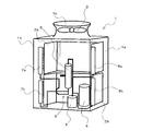
- FIG. 2 is a perspective perspective view showing a heat source side unit of the air conditioner.
- FIG. 3 is a perspective view showing an example of a heat source side heat exchanger of the air conditioner.
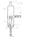
- FIG. 4 is an enlarged view (cross-sectional view) of the main part showing the vicinity of the vertical piping part of the branch circuit of the air conditioner.
- the white arrow of FIG. 1 has shown the flow direction of the refrigerant
- the refrigerant circuit of the air conditioner 10 according to Embodiment 1 includes a compressor 4, a use-side heat exchanger 16 that functions as a condenser during heating operation, a throttling device 15, and a plurality that functions as an evaporator during heating operation.
- These heat source side heat exchangers 2 are sequentially connected by piping.
- the plurality of heat source side heat exchangers 2 are connected in parallel between the expansion device 15 and the suction side of the compressor 4.
- the plurality of heat source side heat exchangers 2 have different heat loads as described later.
- FIG. 1 the example provided with the two heat source side heat exchangers 2 (the upper heat source side heat exchanger 2a and the lower heat source side heat exchanger 2b) is shown.
- the upper heat source side heat exchanger 2a corresponds to the first evaporator of the present invention
- the lower heat source side heat exchanger 2b corresponds to the second evaporator of the present invention.
- the refrigerant circuit of the air conditioner 10 includes a branch circuit 9 provided between the expansion device 15 and the plurality of heat source side heat exchangers 2.
- the branch circuit 9 distributes the refrigerant having a gas-liquid mixing ratio according to the heat load to each of the upper heat source side heat exchanger 2a and the lower heat source side heat exchanger 2b during the heating operation.
- the refrigerant circuit of the air conditioner 10 according to the first embodiment includes the flow path switch 12 on the discharge side of the compressor 4 in order to realize both the cooling operation and the heating operation. Further, the refrigerant circuit of the air conditioner 10 according to the first embodiment also includes an accumulator 5 that suppresses liquid back to the compressor 4 on the suction side of the compressor 4.
- the heat source side unit 1 constitutes a refrigeration cycle that circulates the refrigerant together with the use side unit 14. Specifically, the heat source side unit 1 supplies heat collected from the outdoors to the use side unit 14 during the heating operation. Moreover, the heat source side unit 1 discharges
- the heat source side unit 1 has a housing 11, and a compressor 4, a flow path switch 12, an upper heat source side heat exchanger 2 a, a lower heat source side heat exchanger 2 b, a blower 3, in the housing 11. The accumulator 5 and the branch circuit 9 are accommodated.
- the use side unit 14 is installed in a room or the like to be air-conditioned, and houses the use side heat exchanger 16 and the expansion device 15.
- the air conditioner 10 according to Embodiment 1 includes two usage-side units 14 (a first usage-side unit 14a and a second usage-side unit 14b).
- the first usage side unit 14a houses a first usage side heat exchanger 16a and a first expansion device 15a.
- the second usage side unit 14b houses the second usage side heat exchanger 16b and the second expansion device 15b.
- the first usage side unit 14a and the second usage side unit 14b are connected in parallel. Note that the number of usage-side units 14 is not limited to two, but may be one or three or more.
- the compressor 4 sucks and compresses the refrigerant to bring it into a high temperature / high pressure state, and includes, for example, a scroll compressor, a vane compressor, and the like.
- the flow path switching unit 12 switches between the heating flow path and the cooling flow path in accordance with switching of the operation mode of the cooling operation or the heating operation, and includes, for example, a four-way valve.
- the flow path switch 12 connects the discharge side of the compressor 4 and the use side heat exchanger 16 during the heating operation, and is provided with the heat source side heat exchanger 2 and the suction side of the compressor 4 (accumulator 5 is provided). If it is, connect it to the accumulator 5).
- the flow path switch 12 connects the discharge side of the compressor 4 and the heat source side heat exchanger 2 during the cooling operation, and also uses the heat exchanger 16 on the use side and the suction side (accumulator 5 is connected to the compressor 4). If provided, the accumulator 5) is connected.
- a four-way valve is used as the flow path switching device 12 is illustrated, the present invention is not limited to this. For example, a plurality of two-way valves may be combined. Further, when the air conditioner 10 is configured exclusively for heating operation, it is not particularly necessary to provide the flow path switch 12.
- the heat source side heat exchanger 2 performs heat exchange between the refrigerant and outside air (outdoor air), and is bent into, for example, a U-shape (in other words, a U shape) of the casing 11. It has a different shape.
- the air conditioner 10 according to the first embodiment includes the two heat source side heat exchangers 2 (the upper heat source side heat exchanger 2a and the lower heat source side heat exchanger 2b).
- the lower heat source side heat exchanger 2 b is disposed at the lower part of the housing 11.
- the upper heat source side heat exchanger 2a is disposed on the upper side of the casing 11, that is, above the lower heat source side heat exchanger 2b.
- the housing 11 has a suction port 1a formed in a side surface facing the upper heat source side heat exchanger 2a and the lower heat source side heat exchanger 2b. Heat transfer fins are cut from the upper heat source side heat exchanger 2a and the lower heat source side heat exchanger 2b.
- the heat source side heat exchanger 2 (each of the upper heat source side heat exchanger 2a and the lower heat source side heat exchanger 2b) is configured as shown in FIG. 3, for example.
- the heat source side heat exchanger 2 includes a plurality of heat transfer tubes 40 arranged in the horizontal direction. These heat transfer tubes 40 are arranged side by side with a predetermined interval in the vertical direction.
- the heat transfer tube 40 is, for example, a flat tube, and a plurality of refrigerant channels are formed therein.
- the heat source side heat exchanger 2 includes a plurality of heat transfer fins 41 into which a plurality of heat transfer tubes 40 are inserted.
- heat transfer fins 41 are arranged in parallel in the axial direction of the heat transfer tube 40 with a predetermined interval (for example, 3 mm).
- a predetermined interval for example, 3 mm.
- air flows between the heat transfer fins 41 along the plane of the heat transfer fins 41, as indicated by white arrows in FIG. 3.
- the refrigerant flowing through the refrigerant flow path of the heat transfer tube 40 flows in the axial direction of the heat transfer tube 40.
- waste heat or heat supply is realized by heat exchange between the refrigerant and the outside air.
- a plurality of heat transfer tubes 40 and a plurality of heat transfer fins 41 constitute a heat exchange unit, and a plurality of heat exchange units are arranged side by side along the direction of the outside air flow.
- the exchanger 2 is configured.
- the heat source side heat exchanger 2 includes a merging pipe 8 connected to a plurality of heat transfer pipes 40 and a distributor.
- a header-type distributor 7 is used.
- each heat transfer tube 40 of the upper heat source side heat exchanger 2a is connected to the upper junction tube 8a and the header type upper distributor 7a.
- the upper junction pipe 8a serves as a refrigerant outlet when the upper heat source side heat exchanger 2a functions as an evaporator (during heating operation), and is connected to the flow path switch 12.
- the upper distributor 7a serves as a refrigerant inlet when the upper heat source side heat exchanger 2a functions as an evaporator (at the time of heating operation), and each heat transfer tube of the upper heat source side heat exchanger 2a from the header and the header.
- 40 has a branch pipe connected to 40. During the heating operation, the refrigerant flowing into the upper distributor 7a is distributed from each branch pipe to each heat transfer pipe 40 of the upper heat source side heat exchanger 2a and flows out from the upper junction pipe 8a.
- each heat transfer tube 40 of the lower heat source side heat exchanger 2b is connected to the lower junction tube 8b and the header type lower distributor 7b.
- the lower junction pipe 8b serves as a refrigerant outlet when the lower heat source side heat exchanger 2b functions as an evaporator (during heating operation), and is connected to the flow path switch 12.
- the lower distributor 7b serves as a refrigerant inlet when the lower heat source side heat exchanger 2b functions as an evaporator (at the time of heating operation), and each heat transfer tube of the lower heat source side heat exchanger 2b from the header and the header.
- 40 has a branch pipe connected to 40. In the heating operation, the refrigerant flowing into the lower distributor 7b is distributed from each branch pipe to each heat transfer pipe 40 of the lower heat source side heat exchanger 2b and flows out from the lower junction pipe 8b.
- the blower 3 blows air to the upper heat source side heat exchanger 2a and the lower heat source side heat exchanger 2b.
- the blower outlet 1b is formed in the top
- the air blower 3 makes it compatible not to make an airflow interfere with the compressor 4, the accumulator 5, and the flow path switch 12 in the housing
- the expansion device 15 (the first expansion device 15a and the second expansion device 15b) is provided between the use-side heat exchanger 16 and the branch circuit 9, and adjusts the state of the refrigerant by adjusting the flow rate. It is.
- the throttling device 15 is composed of a throttling device represented by, for example, LEV (linear electronic expansion valve) or the like, or an on-off valve that turns the refrigerant flow on and off by opening and closing.
- the accumulator 5 is provided on the suction side of the compressor 4 and stores the refrigerant. The compressor 4 sucks and compresses the gas-phase refrigerant among the refrigerant stored in the accumulator 5. In the case where the air conditioner 10 is operated only under the condition that the liquid is not returned to the compressor 4, it is not particularly necessary to provide the accumulator 5.
- the branch circuit 9 distributes the refrigerant having a gas-liquid mixing ratio corresponding to the heat load to each of the upper heat source side heat exchanger 2a and the lower heat source side heat exchanger 2b. Specifically, as described later, the heat load on the upper heat source side heat exchanger 2a is larger than the heat load on the lower heat source side heat exchanger 2b. For this reason, the branch circuit 9 is configured to supply a refrigerant having a lower dryness to the upper heat source side heat exchanger 2a than the refrigerant supplied to the lower heat source side heat exchanger 2b.
- the branch circuit 9 includes a gas-liquid separator 6, a main flow pipe 20, a first branch pipe 21a, and a second branch pipe 21b.
- the gas-liquid separator 6 is provided between the expansion device 15 and the heat source side heat exchanger 2, and separates the gas-liquid two-phase refrigerant that has flowed out of the expansion device 15 during heating operation into a gas phase refrigerant and a liquid phase refrigerant. Is.
- One end of the main flow pipe 20 is connected to, for example, the lower part of the gas-liquid separator 6 and supplies liquid-phase refrigerant or gas-liquid two-phase refrigerant to the downstream side during heating operation.
- the first branch pipe 21a has one end connected to the main flow pipe 20 and the other end connected to the upper distributor 7a of the upper heat source side heat exchanger 2a.
- the main flow pipe 20 has a vertical pipe portion 20a arranged in the vertical direction.
- One end of the first branch pipe 21a is connected to, for example, the lower end of the vertical pipe part 20a.
- the second branch pipe 21b has one end connected to the main flow pipe 20 and the other end connected to the lower distributor 7b of the lower heat source side heat exchanger 2b.
- one end of the second branch pipe 21b is connected to the first branch pipe 21a at a position upstream of the connection position between the vertical pipe portion 20a and the first branch pipe 21a in the refrigerant flow direction. Has been.
- the second branch pipe 21 b is arranged along the horizontal direction, and a connection portion between the second branch pipe 21 b and the vertical pipe portion 20 a of the main flow pipe 20 is a T-shaped branch flow path. It has become. Moreover, in this Embodiment 1, it is set as the structure which made the end of the 2nd branch pipe 21b protrude inside the vertical piping part 20a.
- the liquid-phase refrigerant or the gas-liquid two-phase refrigerant that has flowed from the gas-liquid separator 6 into the main flow pipe 20 flows from the upper part to the lower part in the vertical pipe part 20a.
- coolant is distributed by the connection part of the 2nd branch pipe 21b and the vertical piping part 20a of the main flow pipe 20, A part passes through the 2nd branch pipe 21b, and the lower distributor of the lower heat source side heat exchanger 2b Flows into 7b.
- the remaining part of the refrigerant flows into the upper distributor 7a of the upper heat source side heat exchanger 2a through the first branch pipe 21a.
- the liquid-phase refrigerant that has flowed out of the upper distributor 7a flows into the gas-liquid separator 6 through the first branch pipe 21a and the main flow pipe 20. Further, the liquid phase refrigerant flowing out from the lower distributor 7 b flows into the gas-liquid separator 6 through the second branch pipe 21 b and the main flow pipe 20.
- the air conditioner 10 includes a gas phase refrigerant outflow pipe 23 through which the gas phase refrigerant flows out from the gas-liquid separator 6, and a flow rate control device 13 provided in the gas phase refrigerant outflow pipe 23.
- One end of the gas-phase refrigerant outflow pipe 23 is connected to, for example, the upper part of the gas-liquid separator 6.
- the other end of the gas-phase refrigerant outflow pipe 23 is connected to a pipe 42 that connects the heat source side heat exchanger 2 and the flow path switch 12.
- the other end of the gas-phase refrigerant outflow pipe 23 is connected to a pipe 42 that connects the heat source side heat exchanger 2 and the suction side of the compressor 4 during heating operation.
- the flow control device 13 adjusts the outflow amount of the gas-phase refrigerant from the gas-liquid separator 6.
- the flow control device 13 is a throttle device represented by LEV (linear electronic expansion valve) or the like, and ON / OFF of the refrigerant flow by opening and closing. It consists of an on-off valve that turns off.
- LEV linear electronic expansion valve
- a linear electronic expansion valve is used as the flow control device 13.
- the pipe 42 corresponds to the suction pipe of the present invention.
- the gas-phase refrigerant outflow pipe 23 and the flow rate control device 13 are not essential components. Even without these configurations, it is possible to distribute the refrigerant having a gas-liquid mixing ratio corresponding to the heat load to each of the upper heat source side heat exchanger 2a and the lower heat source side heat exchanger 2b. However, the heat exchange performance of the heat source side heat exchanger 2 can be further improved by providing the gas-phase refrigerant outlet pipe 23 and the flow rate control device 13. An example of the control method of the flow control device 13 will be described later in a fifth embodiment.
- the refrigerant becomes a gas-phase refrigerant compressed in the compressor 4 and flows from the compressor 4 to the first usage side heat exchanger 16a and the second usage side heat exchanger 16b via the flow path switch 12.
- the gas-phase refrigerant dissipates heat in the first usage-side heat exchanger 16a and the second usage-side heat exchanger 16b and condenses from gas to liquid, and the condensed refrigerant is the first expansion device 15a and the second expansion device.
- the gas-liquid two-phase refrigerant flows into the gas-liquid separator 6, the gas-phase refrigerant flows through the flow rate control device 13 to the flow path switch 12, and the gas-liquid two-phase or liquid-phase refrigerant is mainstream. It flows into the pipe 20.
- the gas-liquid two-phase or liquid-phase refrigerant flowing into the main flow pipe 20 is distributed to the upper distributor 7a and the lower distributor 7b through the first branch pipe 21a and the second branch pipe 21b.
- the gas-liquid two-phase or liquid-phase refrigerant that has flowed into the upper distributor 7a and the lower distributor 7b is respectively distributed to the plurality of heat transfer tubes 40 and is evaporated by absorbing heat from the air by the blower 3.
- the ratio of the gas in the gas-liquid two-phase state increases in the refrigerant flowing through the heat transfer tubes 40 of the upper heat source side heat exchanger 2a and the lower heat source side heat exchanger 2b.
- the refrigerant that has flowed out of each heat transfer tube 40 flows through the upper merge tube 8a or the lower merge tube 8b, flows with the flow from the flow rate control device 13, and then flows into the accumulator 5 through the flow path switch 12. Thereafter, the refrigerant in the accumulator 5 is sucked into the compressor 4.
- FIG. 5 is a PH cycle diagram when the hydrofluorocarbon refrigerant R410a is used in the air conditioner according to Embodiment 1 of the present invention.
- FIG. 5 has shown the case of said heating operation in which the upper heat source side heat exchanger 2a and the lower heat source side heat exchanger 2b operate as an evaporator.
- a substantially trapezoidal solid line indicates a cycle operation state.
- the convex solid line is a saturation line, and the left region is gas and the right region is liquid.
- Point AB is a superheated gas at the discharge part of the compressor 4.
- the refrigerant is dissipated in the first usage side heat exchanger 16a and the second usage side heat exchanger 16b, so that the point AC is supercooled at the outlet of the first usage side heat exchanger 16a and the second usage side heat exchanger 16b. Become liquid.
- the refrigerant is depressurized by passing through the first expansion device 15a and the second expansion device 15b, and enters a gas-liquid two-phase state with a point AF of about 0.2 dryness.
- the refrigerant in the gas-liquid two-phase state flows into the gas-liquid separator 6 for gas-liquid separation, and the gas-phase refrigerant flows into the point AA of the accumulator 5 via the flow rate control device 13 to be gas-liquid two-phase or liquid-phase.
- the refrigerant flows into the main flow pipe 20.
- the gas-liquid two-phase or liquid-phase refrigerant flowing into the main flow pipe 20 is distributed to the upper distributor 7a and the lower distributor 7b through the first branch pipe 21a and the second branch pipe 21b.
- the gas-liquid two-phase refrigerant at point AD having a relatively low dryness flows into the upper distributor 7a, and the gas-liquid two-phase refrigerant at point AE having a relatively high dryness flows into the lower distributor 7b. Inflow. Thereafter, the refrigerant evaporates in each of the heat transfer tubes 40 of the upper heat source side heat exchanger 2a and the lower heat source side heat exchanger 2b to reach a state point of point AA. It will be described later that the main flow pipe 20, the first branch pipe 21a, and the second branch pipe 21b are branched into different dryness refrigerants.
- a gas-liquid two-phase refrigerant flows into the upper distributor 7a and the lower distributor 7b.
- the gas-liquid two-phase refrigerant includes a mixture of gas and liquid having different densities, and the refrigerant of each phase flows while maintaining a balance between kinetic energy depending on flow velocity and potential energy determined by gravity.
- the liquid refrigerant having a low enthalpy heats from the upper distributor 7a and the lower distributor 7b to the heat transfer tubes 40. It is desirable to distribute according to the load.
- the distance from the upper heat source side heat exchanger 2a to the blower 3 and the distance from the lower heat source side heat exchanger 2b to the blower 3 are different.
- the flow rate of air flowing into the upper heat source side heat exchanger 2a and the flow rate of air flowing into the lower heat source side heat exchanger 2b are also different. That is, the upper heat source side heat exchanger 2a and the lower heat source side heat exchanger 2b have different heat loads.
- the inflow of air into the upper heat source side heat exchanger 2a adjacent to the blower 3 is relatively larger than that of the lower heat source side heat exchanger 2b, so that the heat load is also higher on the lower heat source side. It is larger than the heat exchanger 2b.
- the number of heat transfer fins 41 of the upper heat source side heat exchanger 2a is more densely provided than the lower heat source side heat exchanger 2b.
- the heat transfer area of the upper heat source side heat exchanger 2a is relatively larger than that of the lower heat source side heat exchanger 2b.
- the shape of the heat transfer fin 41 of the upper heat source side heat exchanger 2a is different from that of the lower heat source side heat exchanger 2b, and the heat transfer rate determined by the shape of the heat transfer fin 41 is lower heat source side heat exchanger 2b. May have a larger configuration.
- the upper heat source side heat exchanger 2a and the lower heat source side heat exchanger 2b are provided with the upper distributor 7a and the lower distributor 7b, respectively, upstream of the heat transfer tube 40.
- the distribution of the refrigerant to the upper distributor 7a and the lower distributor 7b is performed in the main flow pipe 20, the first branch pipe 21a, and the second branch pipe 21b.
- FIG. 6 is an essential part enlarged view (sectional view) showing the vicinity of the vertical piping part of the branch circuit of the air conditioner according to Embodiment 1 of the present invention, and the flow state of the refrigerant flowing through the vertical piping part and the second branch pipe Is shown.
- the upper heat source side heat exchanger 2a and the lower heat source side heat exchanger 2b operate as evaporators, the upper heat source side heat exchanger 2a contains more liquid phase refrigerant having a larger latent heat than the lower heat source side heat exchanger 2b. It is necessary to make it flow. Therefore, it is necessary to flow more liquid phase refrigerant into the upper distributor 7a than in the lower distributor 7b.
- the gas-liquid two-phase refrigerant flows vertically downward from the upper part in the main flow pipe 20.
- the liquid phase refrigerant (“A” in FIG. 6) is in the outer peripheral direction, that is, the wall surface side, and the gas phase refrigerant (“B” in FIG. 6) is in the inner peripheral direction. It is unevenly distributed. Since the density of the liquid phase refrigerant is relatively higher than that of the gas phase refrigerant, the descending speed increases due to the influence of gravity.
- the second branch pipe 21b has relatively less liquid refrigerant than the outlet of the main pipe 20, that is, the liquid refrigerant flowing into the first branch pipe 21a relatively increases. Therefore, the lower distributor 7b is connected to the second branch pipe 21b, and the upper distributor 7a is connected to the first branch pipe 21a connected to the main flow pipe 20 at a position below the lower distributor 7b.
- a relatively large amount of liquid-phase refrigerant can flow into the upper heat source side heat exchanger 2a having a large heat load. That is, a refrigerant having a lower dryness than the refrigerant supplied to the lower heat source side heat exchanger 2b can be supplied to the upper heat source side heat exchanger 2a having a large heat load.
- the gas-liquid mixing ratio of the refrigerant flowing into the second branch pipe 21b can be adjusted according to the amount of projection into the main flow pipe 20 at the tip of the second branch pipe 21b. Specifically, the more the tip (that is, the opening) of the second branch pipe 21b is arranged closer to the tube axis of the main flow pipe 20, the easier the gas-phase refrigerant flows into the second branch pipe 21b and the liquid-phase refrigerant flows into the second branch pipe 21b. It becomes difficult to do.
- FIG. 7 is a diagram showing the degree of superheat of the heat transfer tube outlets of the upper heat source side heat exchanger and the lower heat source side heat exchanger of the air conditioner according to Embodiment 1 of the present invention.
- shaft of FIG. 7 has shown each heat exchanger tube 40 of the upper heat source side heat exchanger 2a and the lower heat source side heat exchanger 2b, The heat exchanger tube arrange
- the number is given to 40. Numbers “1” to “16” are the heat transfer tubes 40 of the lower heat source side heat exchanger 2b, and numbers “17” to “33” are the heat transfer tubes 40 of the upper heat source side heat exchanger 2a.
- shaft shows the superheat degree of each heat exchanger tube 40 outlet in case the upper heat source side heat exchanger 2a and the lower heat source side heat exchanger 2b operate
- the degree of superheat is obtained by subtracting the temperature of the gas-liquid two-phase refrigerant flowing into the heat transfer tube 40 from the temperature of the refrigerant at the outlet of the heat transfer tube 40.
- the upper heat source side heat exchanger 2a and the lower heat source side heat exchanger 2b are connected in parallel using the branch circuit 9 as in the first embodiment, so that the heating degree distribution is on the upper heat source side.
- the heat exchanger 2a and the lower heat source side heat exchanger 2b can equalize.
- the branch circuit 9 causes the liquid phase to be transferred to the upper heat source side heat exchanger 2a having a large heat load.
- the heat exchange performance (heat exchange efficiency) of the upper heat source side heat exchanger 2a and the lower heat source side heat exchanger 2b can be increased, and the system performance of the entire air conditioner 10 can be improved.
- connection configuration of the mainstream pipe 20 and the second branch pipe 21b shown in the first embodiment is merely an example. Any structure that can supply a refrigerant having a lower dryness than the refrigerant supplied to the lower heat source side heat exchanger 2b to the upper heat source side heat exchanger 2a having a large heat load may be used. If this condition is satisfied, the installation posture of the main flow pipe 20 and the second branch pipe 21b, the connection angle of the second branch pipe 21b to the main flow pipe 20, and the cross-sectional shapes of the main flow pipe 20 and the second branch pipe 21b are arbitrary. .
- Embodiment 2 The branch circuit that allows a relatively large amount of liquid-phase refrigerant to flow into the upper heat source side heat exchanger 2a having a large heat load is not limited to that shown in the first embodiment.
- the end part of the 2nd branch pipe 21b should just be connected between the expansion apparatus 15 and the connection part of the main flow pipe 20 and the 1st branch pipe 21a.
- the branch circuit may be configured as follows. In the second embodiment, parts having the same configuration as in the first embodiment are given the same reference numerals, and the description thereof is omitted.
- FIG. 8 is a refrigerant circuit diagram illustrating an example of an air conditioner according to Embodiment 2 of the present invention.
- the difference between the air conditioner 110 according to the second embodiment and the air conditioner 10 according to the first embodiment is the configuration of the heat source side heat exchanger 102 and the branch circuit 109.
- the heat source side heat exchanger 102 includes a header 107-type distributor 107 instead of the header-type distributor 7 shown in the first embodiment.
- the air conditioner 110 according to the second embodiment includes two heat source side heat exchangers 102 (an upper heat source side heat exchanger 102a and a lower heat source side heat exchanger 102b) as in the first embodiment. I have.
- the heat transfer tubes 40 of the upper heat source side heat exchanger 102a are connected to the upper distributor 107a, and the heat transfer tubes 40 of the lower heat source side heat exchanger 102b are connected to the lower distributor 107b.
- the heat load of the upper heat source side heat exchanger 102a is larger than the heat load of the lower heat source side heat exchanger 102b.
- the distributor 7 is merely an example.
- the header-type distributor 7 shown in the first embodiment may be used for the heat source side heat exchanger 102.
- a non-header distributor 107 may be used for the heat source side heat exchanger according to the first embodiment and the embodiments described later.
- the branch circuit 109 includes a gas-liquid separator 6, a main flow pipe 20, a first branch pipe 21a, and a second branch pipe 21b, similarly to the branch circuit 9 shown in the first embodiment.
- the first branch pipe 21a has one end connected to the main flow pipe 20 and the other end connected to the upper distributor 107a of the upper heat source side heat exchanger 102a.
- the second branch pipe 21b has one end connected to a position upstream of the gas-liquid separator 6 during heating operation, and the other end connected to the lower distributor 107b of the lower heat source side heat exchanger 102b.
- one end of the second branch pipe 21 b is connected to an inflow pipe 22 that connects the expansion device 15 and the gas-liquid separator 6.
- a connecting portion between the inflow pipe 22 and the second branch pipe 21b is, for example, a Y-shaped branch flow path.
- substantially the same amount of liquid-phase refrigerant branches At the connection portion between the inflow pipe 22 and the second branch pipe 21b, substantially the same amount of liquid-phase refrigerant branches. Accordingly, during the heating operation in which the upper heat source side heat exchanger 102a and the lower heat source side heat exchanger 102b operate as an evaporator, the refrigerant having decreased in dryness after passing through the gas-liquid separator 6 flows into the upper distributor 107a. Then, a relatively dry refrigerant flows into the lower distributor 107b.
- the branch circuit 109 supplies a liquid phase refrigerant to the lower heat source side heat exchanger 102b having a small heat load.
- the heat exchange performance (heat exchange efficiency) of the upper heat source side heat exchanger 102a and the lower heat source side heat exchanger 102b can be increased, and the overall system performance of the air conditioner 110 can be improved.
- Embodiment 3 As described above, the end of the second branch pipe 21b only needs to be connected between the expansion device 15 and the connecting portion between the main flow pipe 20 and the first branch pipe 21a. For this reason, for example, a branch circuit can be configured as follows.
- parts having the same configuration as those in the first or second embodiment are denoted by the same reference numerals. Further, matters not mentioned in the third embodiment are the same as those in the first or second embodiment.
- FIG. 9 is a refrigerant circuit diagram illustrating an example of an air conditioner according to Embodiment 3 of the present invention.
- FIG. 10 is an enlarged view (cross-sectional view) of a main part showing the vicinity of the gas-liquid separator of the branch circuit of the air conditioner.
- FIG. 10 is an enlarged view (cross-sectional view) of the main part showing the vicinity of the gas-liquid separator of the branch circuit of the air conditioner, and shows the flow state of the refrigerant flowing through the gas-liquid separator.
- the difference between the air conditioner 210 according to the third embodiment and the air conditioner 10 according to the first embodiment is the configuration of the branch circuit 209.
- an inflow pipe 22 that connects the expansion device 15 and the gas-liquid separator 6 is connected, for example, substantially horizontally at the center of the side surface. Further, the gas-liquid separator 6 is connected to a gas-phase refrigerant outflow pipe 23 for allowing the gas-phase refrigerant to flow out from the gas-liquid separator 6, for example. Moreover, the mainstream pipe
- the gas-liquid two-phase refrigerant flows into the gas-liquid separator 6 from the inflow pipe 22.
- a liquid-phase refrigerant (“A” in FIG. 11), a gas-phase refrigerant (“B” in FIG. 11), and a gas-liquid two-phase refrigerant (“B” in FIG. 11) due to the balance between gravity and inertial force. It is separated into “C” in FIG.
- the main flow pipe 20 opens at a position below the second branch pipe 21b. For this reason, it is possible to selectively flow out the liquid refrigerant generated at the bottom of the gas-liquid separator 6.
- the gas-liquid separator 6 supplies liquid to the upper heat source side heat exchanger 202a having a large heat load.
- the heat exchange performance (heat exchange efficiency) of the upper heat source side heat exchanger 2a and the lower heat source side heat exchanger 2b is increased and the system performance of the entire air conditioner 210 is improved. it can.
- Embodiment 4 As described above, the end of the second branch pipe 21b only needs to be connected between the expansion device 15 and the connecting portion between the main flow pipe 20 and the first branch pipe 21a. For this reason, for example, a branch circuit can be configured as follows.
- parts having the same configuration as in any of the first to third embodiments are given the same reference numerals. Further, matters not mentioned in the fourth embodiment are the same as those in any one of the first to third embodiments.
- FIG. 12 is a refrigerant circuit diagram illustrating an example of an air conditioner according to Embodiment 4 of the present invention.
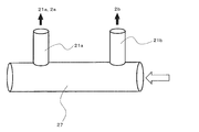
- FIG. 13 is an enlarged view (cross-sectional view) of a main part showing the vicinity of the horizontal piping part of the branch circuit of the air conditioner.
- FIG. 14 is an enlarged view (cross-sectional view) of the main part showing the vicinity of the horizontal pipe part of the branch circuit of the air conditioner, and shows the flow state of the refrigerant flowing through the horizontal pipe part.
- the difference between the air conditioner 310 according to the fourth embodiment and the air conditioner 10 according to the first embodiment is the configuration of the branch circuit 309.
- the main flow pipe 20 of the branch circuit 309 has a horizontal pipe section 27 arranged in the horizontal direction with the opening of the end section closed on the end section side not connected to the gas-liquid separator 6. Yes. And the 1st branch pipe 21a connected to the upper heat source side heat exchanger 2a with a large heat load is connected to this horizontal piping part 27 substantially vertically, for example. Further, the second branch pipe 21b connected to the lower heat source side heat exchanger 2b having a small heat load is located upstream in the refrigerant flow direction during heating operation from the connection position between the horizontal pipe portion 27 and the first branch pipe 21a. For example, the horizontal pipe portion 27 is connected substantially vertically to the horizontal piping portion 27.
- the gas-liquid two-phase refrigerant flows into the horizontal piping part 27 from the direction of the white arrow shown in FIGS. To do.
- the liquid phase refrigerant having a large inertial force tends to be unevenly distributed at the end portion of the horizontal pipe portion 27. Therefore, a refrigerant with high dryness flows into the second branch pipe 21b near the inlet of the horizontal pipe section 27, and a refrigerant with low dryness flows into the first branch pipe 21a far away.
- the liquid phase is transferred to the upper heat source side heat exchanger 2a having a large heat load in the horizontal pipe portion 27.
- the heat exchange performance (heat exchange efficiency) of the upper heat source side heat exchanger 2a and the lower heat source side heat exchanger 2b can be increased, and the overall system performance of the air conditioner 310 can be improved.
- Embodiment 5 The flow control device 13 shown in the first to fourth embodiments is controlled as follows, for example.
- parts having the same configuration as in any of the first to fourth embodiments are denoted by the same reference numerals. Further, matters not mentioned in the fifth embodiment are the same as those in the first to fourth embodiments. Further, in the fifth embodiment, an example of the control method of the flow control device 13 will be described using the refrigerant circuit of the air conditioner shown in the first embodiment as an example.
- FIG. 15 is a refrigerant circuit diagram illustrating an example of an air conditioner according to Embodiment 5 of the present invention.
- FIG. 16 is a flowchart showing an example of a control method of the air conditioner flow control device.
- the flow control device 13 for example, the inlet temperature detection device 31, the outlet temperature detection device 32, the merging temperature detection device 33, the flow control device control unit 35, and the calculation unit 35 a are provided in the refrigerant circuit of the air conditioner 410. .
- the inlet temperature detection device 31 which is a temperature sensor such as a thermistor is provided in the second branch pipe 21b and detects the refrigerant temperature at the position.
- the outlet temperature detection device 32 which is a temperature sensor such as a thermistor, is provided in a pipe 42 that connects the heat source side heat exchanger 2 and the flow path switch 12, and detects the refrigerant temperature at the position. More specifically, the outlet temperature detection device 32 is provided at a position upstream of the connection portion between the pipe 42 and the gas-phase refrigerant outflow pipe 23 in the refrigerant flow direction during heating operation.
- the confluence temperature detection device 33 which is a temperature sensor such as a thermistor, is provided in the pipe 42 that connects the heat source side heat exchanger 2 and the flow path switch 12, and detects the refrigerant temperature at the position. More specifically, the merging temperature detection device 33 is provided at a position downstream of the connecting portion between the pipe 42 and the gas-phase refrigerant outflow pipe 23 in the refrigerant flow direction during the heating operation.
- the calculation unit 35a is constituted by, for example, a microcomputer and receives output signals (detection values) from the inlet temperature detection device 31, the outlet temperature detection device 32, and the merging temperature detection device 33. And the calculating part 35a subtracts the detected value of the inlet temperature detection apparatus 31 from the detected value of the outlet temperature detection apparatus 32, and calculates a heat exchanger superheat degree. In addition, the calculation unit 35a subtracts the detection value of the inlet temperature detection device 31 from the detection value of the merging temperature detection device 33 to calculate the merging superheat degree.
- the flow control device control unit 35 is constituted by, for example, a microcomputer.
- the flow control device control unit 35 transmits a control signal to the flow control device 13 based on the heat exchanger superheat degree and the combined superheat degree calculated by the calculation unit 35a to control the opening degree of the flow control device 13. .
- the opening degree control of the flow rate control device 13 is performed at predetermined time intervals, for example.
- the flow control device controller 35 controls the opening degree of the flow control device 13 as shown in FIG. That is, the flow control device control unit 35 increases the opening degree of the flow control device 13 when the heat exchanger superheat degree> 0 and the combined superheat degree> 0. Further, the flow control device control unit 35 reduces the opening degree of the flow control device 13 when the heat exchanger superheat degree> 0 and the combined superheat degree ⁇ 0. Moreover, the flow control device control unit 35 increases the opening degree of the flow control device 13 when the heat exchanger superheat degree ⁇ 0.
- the heat source side heat exchanger 2 When the heat exchanger superheat degree> 0 and the combined superheat degree> 0, the heat source side heat exchanger 2 is in a superheated state and the liquid back of the gas-liquid separator 6 is not generated. For this reason, the heat source side heat exchanger 2 can further exchange heat by increasing the flow rate of the gas-phase refrigerant flowing out from the gas-liquid separator 6 to the flow path switch 12. Therefore, the flow control device control unit 35 increases the opening degree of the flow control device 13 and increases the flow rate of the gas phase refrigerant flowing out from the gas-liquid separator 6 to the flow path switch 12.
- the heat source side heat exchanger 2 When the heat exchanger superheat degree> 0 and the combined superheat degree ⁇ 0, the heat source side heat exchanger 2 is in a superheated state, and the liquid back of the gas-liquid separator 6 is generated. In this state, a large amount of liquid-phase refrigerant flows into the gas-phase refrigerant flowing out from the gas-liquid separator 6 to the flow path switch 12, and the refrigerant existing in the refrigerant circuit is stored in the accumulator 5, and heat source side heat exchange is performed. This is a state in which the thermal load of the vessel 2 is decreasing.
- the flow control device control unit 35 decreases the opening degree of the flow control device 13, reduces the flow rate of the gas-phase refrigerant flowing out from the gas-liquid separator 6 to the flow path switch 12, and The liquid back is prevented and the accumulation of the refrigerant in the accumulator 5 is eliminated. Thereby, the overheating state in the heat source side heat exchanger 2 is eliminated.
- the flow control device controller 35 increases the opening degree of the flow control device 13. Then, the amount of refrigerant circulating in the refrigerant circuit decreases, and the outlet of the heat source side heat exchanger 2 becomes overheated.
- the heat exchange performance (heat exchange efficiency) of the upper heat source side heat exchanger 2a and the lower heat source side heat exchanger 2b.
- the system performance of the entire air conditioner 410 can be further improved.
- Embodiment 6 The flow control device 30 for adjusting the amount of refrigerant flowing through the second branch pipe 21b may be provided in the second branch pipe 21b of the refrigerant circuit of the air conditioner shown in the first to fifth embodiments.
- parts having the same configuration as in any of the first to fifth embodiments are denoted by the same reference numerals. Further, matters not mentioned in the sixth embodiment are the same as those in any of the first to fifth embodiments.
- an example in which the flow control device 30 is provided in the air conditioner shown in the fifth embodiment will be described.
- FIG. 17 is a refrigerant circuit diagram illustrating an example of an air conditioner according to Embodiment 6 of the present invention.
- the air conditioner 510 according to the sixth embodiment includes a flow rate control device 30 and a flow rate control device control unit 34 in addition to the configuration of the air conditioner 410 shown in the fifth embodiment.
- the flow controller 30 adjusts the amount of refrigerant flowing through the second branch pipe 21b, that is, the amount of refrigerant flowing into the lower heat source side heat exchanger 2b.
- the flow rate control is performed so that the inlet temperature detector 31 can detect the temperature of the refrigerant flowing into the lower heat source side heat exchanger 2b during the heating operation.
- the device 30 is provided upstream of the inlet temperature detection device 31 in the refrigerant flow direction during the heating operation.
- the flow control device 30 is a throttle device represented by, for example, LEV (linear electronic expansion valve).
- the flow control device control unit 34 is configured by, for example, a microcomputer and transmits a control signal to the flow control device 30 to control the opening degree of the flow control device 30.
- the upper heat source side heat exchanger 2a and the lower heat source side heat exchanger 2b in addition to the gas-liquid mixing ratio of the refrigerant flowing into the upper heat source side heat exchanger 2a and the lower heat source side heat exchanger 2b, the upper heat source side heat exchanger 2a and the lower heat source side heat exchanger It is also possible to adjust the amount of refrigerant flowing into 2b. For this reason, the heat exchange performance (heat exchange efficiency) of the upper heat source side heat exchanger 2a and the lower heat source side heat exchanger 2b can be further increased, and the system performance of the entire air conditioner 510 can be further improved.
- Embodiment 7 The heat source side heat exchanger that can be connected in parallel to the branch circuit of the present invention is not limited to two.
- an example in which four heat source side heat exchangers are connected in parallel to the branch circuit will be described.
- parts having the same configurations as those in any of the first to sixth embodiments are denoted by the same reference numerals. Further, matters not mentioned in the seventh embodiment are the same as those in any one of the first to sixth embodiments.
- the branch circuit shown in the fourth embodiment will be described.
- FIG. 18 is a perspective perspective view showing a heat source side unit of an air conditioner according to Embodiment 7 of the present invention.
- FIG. 19 is a refrigerant circuit diagram illustrating an example of an air conditioner according to Embodiment 7 of the present invention.
- FIG. 20 is an enlarged view (cross-sectional view) showing the vicinity of the horizontal piping portion of the branch circuit of the air conditioner according to Embodiment 7 of the present invention, and shows the flow state of the refrigerant flowing through the horizontal piping portion.
- the air conditioner 610 according to the seventh embodiment includes four heat source side heat exchangers.
- the air conditioner 610 includes two heat source side units (a first heat source side unit 501A and a second heat source side unit 501B).
- the first heat source side unit 501A and the second heat source side unit 501B each house two heat source side heat exchangers.
- the casing of the first heat source side unit 501A has the same shape as the casing 11 shown in the first embodiment, and the first blower 503a is provided at the outlet formed on the top surface.
- two heat source side heat exchangers are arranged in the vertical direction in the casing of the first heat source side unit 501A. These heat source side heat exchangers have the same shape as the heat source side heat exchanger 2 shown in the first embodiment.
- the heat source side heat exchanger disposed on the upper side is referred to as a first upper heat source side heat exchanger 502a
- the heat source side heat exchanger disposed on the lower side is referred to as the first lower heat source side heat exchanger. This is referred to as a device 502b.
- the first upper heat source side heat exchanger 502a includes a first upper distributor 507a having the same configuration as that of the distributor 7 shown in the first embodiment and a first pipe having the same configuration as that of the junction pipe 8 shown in the first embodiment.
- An upper junction pipe 508a is provided.
- a branch pipe 36 is connected to the first upper distributor 507a.
- the first lower heat source side heat exchanger 502b has the same configuration as the first lower distributor 507b having the same configuration as the distributor 7 shown in the first embodiment and the junction pipe 8 shown in the first embodiment.
- the first lower junction pipe 508b is provided.
- a branch pipe 38 is connected to the first lower distributor 507b. That is, the heat load of the first upper heat source side heat exchanger 502a is larger than the heat load of the first lower heat source side heat exchanger 502b.
- the housing of the second heat source side unit 501B has the same shape as the housing 11 shown in the first embodiment, and the second blower 503b is provided at the air outlet formed on the top surface.
- two heat source side heat exchangers are arranged in the vertical direction in the casing of the second heat source side unit 501B. These heat source side heat exchangers have the same shape as the heat source side heat exchanger 2 shown in the first embodiment.
- the heat source side heat exchanger disposed on the upper side is referred to as a second upper heat source side heat exchanger 502c
- the heat source side heat exchanger disposed on the lower side is referred to as a second lower heat source side heat exchanger. This is referred to as 502d.
- the second upper heat source side heat exchanger 502c is a second upper distributor 507c having the same configuration as that of the distributor 7 shown in the first embodiment and a second pipe having the same configuration as that of the junction pipe 8 shown in the first embodiment.
- An upper junction pipe 508c is provided.
- a branch pipe 37 is connected to the second upper distributor 507c.
- the second lower heat source side heat exchanger 502d is a second lower distributor 507d having the same configuration as the distributor 7 shown in the first embodiment and a second lower distributor 507d having the same configuration as the junction pipe 8 shown in the first embodiment.
- Two lower joining pipes 508d are provided.
- a branch pipe 39 is connected to the second lower distributor 507d. That is, the heat load of the second upper heat source side heat exchanger 502c is larger than the heat load of the second lower heat source side heat exchanger 502d.
- the heat load of the first upper heat source side heat exchanger 502a is larger than the heat load of the second upper heat source side heat exchanger 502c, and the second upper heat source side heat exchanger 502a
- the heat load of the heat exchanger 502c is larger than the heat load of the first lower heat source side heat exchanger 502b
- the heat load of the first lower heat source side heat exchanger 502b is the second lower heat source side heat exchanger.
- the configuration is larger than the thermal load of 502d. That is, the magnitude of the heat load is as follows: first upper heat source side heat exchanger 502a> second upper heat source side heat exchanger 502c> first lower heat source side heat exchanger 502b> second lower heat source side heat exchanger 502d. It has become.
- the first upper heat source side heat exchanger 502a, the first lower heat source side heat exchanger 502b, the second upper heat source side heat exchanger 502c, and the second lower heat source side heat exchanger 502d are evaporators.
- the gas-liquid two-phase refrigerant flows into the horizontal piping part 27 of the branch circuit 509 from the direction of the white arrow.
- the liquid phase refrigerant having a large inertial force tends to be unevenly distributed at the end portion of the horizontal pipe portion 27. Therefore, the branch pipes connected to the heat source side heat exchanger having a large heat load are connected in order, for example, substantially vertically from the terminal end of the horizontal piping part 27 toward the inlet side.
- the pipe 37, the branch pipe 38 connected to the first lower heat source side heat exchanger 502b, and the branch pipe 39 connected to the second lower heat source side heat exchanger 502d are connected in this order.
- the gas-liquid two-phase refrigerant having a lower dryness flows into the branch pipe connected to the position closer to the terminal end of the horizontal pipe section 27. That is, a gas-liquid two-phase refrigerant having a lower dryness flows into the heat source side heat exchanger with a larger heat load.
- the first upper heat source side heat exchanger 502a, the first lower heat source side heat exchanger 502b, the second upper heat source side heat exchanger 502c, and the second lower heat source side heat exchanger 502d are provided.
- the first upper heat source side heat exchanger 502a, the first lower The heat exchange performance (heat exchange efficiency) of the partial heat source side heat exchanger 502b, the second upper heat source side heat exchanger 502c, and the second lower heat source side heat exchanger 502d is increased, and the system performance of the entire air conditioner 610 is improved. it can.
- Embodiment 8 FIG.
- casing was assumed.
- the present invention is not limited to this, and the present invention can also be implemented for an air conditioner including a heat source unit having another configuration. Hereinafter, an example of such an air conditioner will be described.
- parts having the same configuration as in any of the first to seventh embodiments are denoted by the same reference numerals. Further, matters not mentioned in the eighth embodiment are the same as those in the first to seventh embodiments.
- FIG. 21 is a perspective view showing a heat source side unit of an air conditioner according to Embodiment 8 of the present invention.
- the heat source side unit 601 of the air conditioner 710 according to the eighth embodiment includes a housing 611 in which a suction port 601a and a blower outlet 601b are formed on a side surface portion.
- casing 611 the upper heat source side heat exchanger 2a and the lower heat source side heat exchanger 2b are arranged in parallel by the up-down direction so as to oppose the suction inlet 601a. Note that these heat source side heat exchangers may be juxtaposed in the horizontal direction.
- the 1st air blower 603a and the 2nd air blower 603b are provided in the blower outlet 601b.
- the 1st air blower 603a is arrange
- the 2nd air blower 603b is arrange
- the air conditioner 710 configured as described above, when the circulation amount of the refrigerant decreases during low-capacity operation or the like, a large amount of liquid phase refrigerant is supplied to one heat source side heat exchanger, and the heat source side heat is supplied. It is better to increase the rotational speed of the blower corresponding to the exchanger than the other. This is because the refrigerant is uniformly distributed to the heat transfer tubes of the heat source side heat exchanger. At this time, since the rotation speed of the other blower, that is, power consumption can be reduced, energy saving is comprehensively achieved.
- the refrigerant circuit of the air conditioner 710 according to the eighth embodiment is the upper heat source side heat exchanger 2a.
- a refrigerant having a lower dryness than the refrigerant supplied to the lower heat source side heat exchanger 2b can be supplied. That is, more liquid phase refrigerant can be supplied to the upper heat source side heat exchanger 2a than the lower heat source side heat exchanger 2b.
- the air conditioner 710 according to the eighth embodiment includes the first blower 603a that supplies air to the upper heat source side heat exchanger 2a when the circulation amount of the refrigerant decreases during low-capacity operation or the like. Energy saving of the air conditioner 710 can be realized by increasing the number of rotations and decreasing the number of rotations of the second blower 603b.
Abstract
Description
図1は、本発明の実施の形態1による空気調和機の一例を示す冷媒回路図である。図2は、この空気調和機の熱源側ユニットを示す斜視透視図である。図3は、この空気調和機の熱源側熱交換器の一例を示す斜視図である。また、図4は、この空気調和機の分岐回路の垂直配管部近傍を示す要部拡大図(断面図)である。なお、図1の白抜き矢印は、暖房運転時の冷媒の流れ方向を示している。
ここで、上部熱源側熱交換器2aが本発明の第一蒸発器に相当し、下部熱源側熱交換器2bが本発明の第二蒸発器に相当する。
なお、利用側ユニット14の数は2つに限定されるものではなく、1つであってもよいし、3つ以上あってもよい。
まず、冷媒が圧縮機4において圧縮された気相冷媒になり、圧縮機4から流路切替器12を介して第一利用側熱交換器16a及び第二利用側熱交換器16bへと流れる。その後、気相冷媒は、第一利用側熱交換器16a及び第二利用側熱交換器16bにおいて放熱して気体から液体へと凝縮し、凝縮した冷媒が第一絞り装置15a及び第二絞り装置15bにおいて減圧されることで気液二相状態となる。そして、気液二相状態の冷媒が気液分離器6へと流入し、気相冷媒が流量制御装置13を通じて流路切替器12へ流通し、他方気液二相又は液相の冷媒が主流管20へ流入する。主流管20に流入した気液二相又は液相の冷媒は、第一分岐管21a及び第二分岐管21bを介して上部分配器7a及び下部分配器7bへと分配される。上部分配器7a及び下部分配器7bに流入した気液二相又は液相の冷媒は、各々、複数の伝熱管40に分配され、送風機3の送風により空気から吸熱することで蒸発する。これにより、上部熱源側熱交換器2a及び下部熱源側熱交換器2bの各伝熱管40内を流れる冷媒は、気液二相状態の気体の割合が上昇する。その後、各伝熱管40から流出した冷媒は、上部合流管8a又は下部合流管8bを経て、流量制御装置13からの流れと合流の後、流路切替器12を経てアキュムレータ5に流れる。その後、アキュムレータ5内の冷媒が圧縮機4へと吸入される。
上部熱源側熱交換器2a及び下部熱源側熱交換器2bが蒸発器として動作する場合、上部熱源側熱交換器2aには下部熱源側熱交換器2bよりも潜熱が大きな液相の冷媒を多く流入させる必要がある。従って、上部分配器7aに下部分配器7bよりも多くの液相の冷媒を流入させる必要がある。
図7に示すように、本実施の形態1のように分岐回路9を用いて上部熱源側熱交換器2a及び下部熱源側熱交換器2bを並列接続することにより、加熱度分布が上部熱源側熱交換器2a及び下部熱源側熱交換器2bで均一化できる。
熱負荷の大きな上部熱源側熱交換器2aに液相冷媒を相対的に多く流入させる分岐回路は、実施の形態1で示したものに限定されるものではない。第二分岐管21bの端部は、絞り装置15から主流管20と第一分岐管21aとの接続部までの間に接続されていればよい。例えば以下のように分岐回路を構成してもよい。なお、本実施の形態2では、実施意の形態1と同一の構成を有する部位には同一の符号を付し、その説明を省略する。
上述のように、第二分岐管21bの端部は、絞り装置15から主流管20と第一分岐管21aとの接続部までの間に接続されていればよい。このため、例えば以下のように分岐回路を構成することもできる。なお、本実施の形態3では、実施の形態1又は実施の形態2と同一の構成を有する部位には同一の符号を付す。また、本実施の形態3で言及していない事項については、実施の形態1又は実施の形態2と同様とする。
本実施の形態3に係る空気調和機210が実施の形態1に係る空気調和機10と異なる点は、分岐回路209の構成である。
上述のように、第二分岐管21bの端部は、絞り装置15から主流管20と第一分岐管21aとの接続部までの間に接続されていればよい。このため、例えば以下のように分岐回路を構成することもできる。なお、本実施の形態4では、実施の形態1~実施の形態3のいずれかと同一の構成を有する部位には同一の符号を付す。また、本実施の形態4で言及していない事項については、実施の形態1~実施の形態3のいずれかと同様とする。
本実施の形態4に係る空気調和機310が実施の形態1に係る空気調和機10と異なる点は、分岐回路309の構成である。
実施の形態1~実施の形態4で示した流量制御装置13は、例えば以下のように制御される。なお、本実施の形態5では、実施の形態1~実施の形態4のいずれかと同一の構成を有する部位には同一の符号を付す。また、本実施の形態5で言及していない事項については、実施の形態1~実施の形態4のいずれかと同様とする。また、本実施の形態5では、実施の形態1で示した空気調和機の冷媒回路を例に、流量制御装置13の制御方法の一例を説明する。
流量制御装置13を制御する場合、例えば、入口温度検出装置31、出口温度検出装置32、合流温度検出装置33、流量制御装置制御部35及び演算部35aを、空気調和機410の冷媒回路に設ける。
実施の形態1~実施の形態5で示した空気調和機の冷媒回路の第二分岐管21bに、該第二分岐管21bを流れる冷媒量を調節する流量制御装置30を設けてもよい。なお、本実施の形態6では、実施の形態1~実施の形態5のいずれかと同一の構成を有する部位には同一の符号を付す。また、本実施の形態6で言及していない事項については、実施の形態1~実施の形態5のいずれかと同様とする。また、本実施の形態6では、実施の形態5で示した空気調和機に流量制御装置30を設けた例について説明する。
本実施の形態6に係る空気調和機510は、実施の形態5で示した空気調和機410の構成に加え、流量制御装置30及び流量制御装置制御部34を備えている。流量制御装置30は、第二分岐管21bを流れる冷媒量、つまり、下部熱源側熱交換器2bに流入する冷媒量を調節するものである。第二分岐管21bに入口温度検出装置31が設けられている場合、暖房運転時に下部熱源側熱交換器2bへ流入する冷媒の温度を入口温度検出装置31で検出できるようにするため、流量制御装置30は、入口温度検出装置31よりも、暖房運転時における冷媒流れ方向の上流側に設けられる。流量制御装置30は、例えばLEV(リニア電子膨張弁)等に代表される絞り装置である。流量制御装置制御部34は、例えばマイコン等で構成されており、流量制御装置30に制御信号を発信し、流量制御装置30の開度を制御する。
本発明の分岐回路に並列接続できる熱源側熱交換器は、2つに限定されるものではない。以下に、分岐回路に4つの熱源側熱交換器を並列接続する例について説明する。なお、本実施の形態7では、実施の形態1~実施の形態6のいずれかと同一の構成を有する部位には同一の符号を付す。また、本実施の形態7で言及していない事項については、実施の形態1~実施の形態6のいずれかと同様とする。また、本実施の形態7では、実施の形態4で示した分岐回路を用いた例について説明する。
本実施の形態7に係る空気調和機610は、4つの熱源側熱交換器を備えている。また、空気調和機610は、2つの熱源側ユニット(第一熱源側ユニット501A及び第二熱源側ユニット501B)を備えている。第一熱源側ユニット501A及び第二熱源側ユニット501Bは、それぞれ、2つずつ熱源側熱交換器を収納している。
上記の実施の形態では、筐体の天面に送風機が配置された熱源側ユニットを備えた空気調和機を想定していた。これに限らず、その他の構成の熱源ユニットを備えた空気調和機に対しても、本発明を実施することができる。以下、そのような空気調和機の一例について説明する。なお、本実施の形態8では、実施の形態1~実施の形態7のいずれかと同一の構成を有する部位には同一の符号を付す。また、本実施の形態8で言及していない事項については、実施の形態1~実施の形態7のいずれかと同様とする。
本実施の形態8に係る空気調和機710の熱源側ユニット601は、側面部に吸込口601a及び吹出口601bが形成された筐体611を備えている。この筐体611内には、吸込口601aと対向するように、上部熱源側熱交換器2a及び下部熱源側熱交換器2bが上下方向に並設されている。なお、これらの熱源側熱交換器を横方向に並設してもよい。
Claims (13)
- 圧縮機、凝縮器、絞り装置及び熱負荷が異なる複数の蒸発器を備え、
複数の前記蒸発器が、前記絞り装置と前記圧縮機の吸入側との間で並列に接続された冷媒回路において、
前記絞り装置と複数の前記蒸発器との間に設けられ、複数の前記蒸発器のそれぞれに冷媒を分配する分岐回路を備え、
該分岐回路は、前記蒸発器の1つである第一蒸発器に対して、当該第一蒸発器よりも熱負荷が小さい前記蒸発器である第二蒸発器に供給する冷媒よりも、乾き度の小さい冷媒を供給する構成である冷媒回路。 - 前記分岐回路は、
前記絞り装置と複数の前記蒸発器との間に設けられた気液分離器と、
一端が前記気液分離器に接続され、下流側に液相冷媒又は気液二相冷媒を供給する主流管と、
一端が前記主流管に接続され、他端が前記第一蒸発器に接続された第一分岐管と、
一端が前記絞り装置から前記主流管と前記第一分岐管との接続部までの間に接続され、他端が前記第二蒸発器に接続された第二分岐管と、
を備えた請求項1に記載の冷媒回路。 - 前記主流管は、垂直方向に配置された垂直配管部を有し、
前記第一分岐管の一端は、前記垂直配管部に接続され、
前記第二分岐管の一端は、前記垂直配管部と前記第一分岐管との接続位置よりも冷媒流れ方向の上流側となる位置において、前記垂直配管部に接続されている請求項2に記載の冷媒回路。 - 前記第二分岐管の一端は、前記垂直配管部の内部に突出している請求項3に記載の冷媒回路。
- 前記第二分岐管の一端は、前記絞り装置と前記気液分離器とを接続する配管に接続されている請求項2に記載の冷媒回路。
- 前記第二分岐管の一端は、前記気液分離器に接続され、
前記主流管及び前記第二分岐管は、前記気液分離器内で開口し、
前記主流管は、前記第二分岐管よりも下方となる位置に開口している請求項2に記載の冷媒回路。 - 前記主流管は、前記気液分離器と接続されていない側の端部側に、該端部が閉塞されて水平方向に配置された水平配管部を有し、
前記第一分岐管の一端は、前記水平配管部に接続され、
前記第二分岐管の一端は、前記水平配管部と前記第一分岐管との接続位置よりも冷媒流れ方向の上流側となる位置において、前記水平配管部に接続されている請求項2に記載の冷媒回路。 - 一端が前記気液分離器に接続され、他端が前記蒸発器と前記圧縮機の吸入側とを接続する吸入配管に接続されて、前記気液分離器で分離された気相冷媒を前記気液分離器から流出させる気相冷媒流出配管と、
該気相冷媒流出配管に設けられ、前記気液分離器からの前記気相冷媒の流出量を調節する流量制御装置と、
を備えた請求項2~請求項7のいずれか一項に記載の冷媒回路。 - 前記第二分岐管に設けられた入口温度検出装置と、
前記吸入配管において、前記吸入配管と前記気相冷媒流出配管との接続部よりも冷媒流れ方向の上流側となる位置に設けられた出口温度検出装置と、
前記吸入配管において、前記吸入配管と前記気相冷媒流出配管との接続部よりも冷媒流れ方向の下流側となる位置に設けられた合流温度検出装置と、
該流量制御装置の開度を制御する流量制御装置制御部と、
前記出口温度検出装置の検出値から前記入口温度検出装置の検出値を減算した値である熱交換器過熱度、及び、前記合流温度検出装置の検出値から前記入口温度検出装置の検出値を減算した値である合流過熱度を算出する演算部と、
を備え、
前記流量制御装置制御部は、
前記熱交換器過熱度>0かつ前記合流過熱度>0のとき、前記流量制御装置の開度を増加させ、
前記熱交換器過熱度>0かつ前記合流過熱度<0のとき、前記流量制御装置の開度を減少させ、
前記熱交換器過熱度<0のとき、前記流量制御装置の開度を増加させる構成である請求項8に記載の冷媒回路。 - 前記第二分岐管に、該第二分岐管を流れる冷媒量を調節する流量制御装置を備えた請求項2~請求項9のいずれか一項に記載の冷媒回路。
- 複数の前記蒸発器は、
水平方向に配置された複数の伝熱管と、
前記分岐回路に接続され、前記分岐回路から流入した冷媒を複数の前記伝熱管に分配する分配器と、
を備えた請求項1~請求項10のいずれか一項に記載の冷媒回路。 - 請求項1~請求項11のいずれか一項に記載の冷媒回路と、
側面部に吸込口が形成され、天面に吹出口が形成された筐体と、
該筐体の吹出口に設けられた送風機と、
を備え、
複数の前記蒸発器は前記吸込口と対向するように前記筐体に収容されており、前記第一蒸発器が前記第二蒸発器よりも上方に配置されている空気調和機。 - 請求項1~請求項11のいずれか一項に記載の冷媒回路と、
側面部に吸込口及び吹出口が形成された筐体と、
該筐体の吹出口に設けられた複数の送風機と、
を備え、
複数の前記蒸発器は、前記吸込口と対向するように並設され、
複数の前記送風機のそれぞれは、複数の前記蒸発器のそれぞれに対向して配置されている空気調和機。
Priority Applications (4)
| Application Number | Priority Date | Filing Date | Title |
|---|---|---|---|
| US15/575,417 US11320175B2 (en) | 2015-06-17 | 2015-06-17 | Refrigerant circuit |
| JP2017524211A JP6366837B2 (ja) | 2015-06-17 | 2015-06-17 | 冷媒回路及び空気調和機 |
| EP15895602.9A EP3312527B1 (en) | 2015-06-17 | 2015-06-17 | Refrigerant circuit and air conditioner |
| PCT/JP2015/067486 WO2016203581A1 (ja) | 2015-06-17 | 2015-06-17 | 冷媒回路及び空気調和機 |
Applications Claiming Priority (1)
| Application Number | Priority Date | Filing Date | Title |
|---|---|---|---|
| PCT/JP2015/067486 WO2016203581A1 (ja) | 2015-06-17 | 2015-06-17 | 冷媒回路及び空気調和機 |
Publications (1)
| Publication Number | Publication Date |
|---|---|
| WO2016203581A1 true WO2016203581A1 (ja) | 2016-12-22 |
Family
ID=57545137
Family Applications (1)
| Application Number | Title | Priority Date | Filing Date |
|---|---|---|---|
| PCT/JP2015/067486 WO2016203581A1 (ja) | 2015-06-17 | 2015-06-17 | 冷媒回路及び空気調和機 |
Country Status (4)
| Country | Link |
|---|---|
| US (1) | US11320175B2 (ja) |
| EP (1) | EP3312527B1 (ja) |
| JP (1) | JP6366837B2 (ja) |
| WO (1) | WO2016203581A1 (ja) |
Cited By (5)
| Publication number | Priority date | Publication date | Assignee | Title |
|---|---|---|---|---|
| WO2018185922A1 (ja) * | 2017-04-07 | 2018-10-11 | 三菱電機株式会社 | 空気調和機 |
| CN109425139A (zh) * | 2017-09-04 | 2019-03-05 | Bsh家用电器有限公司 | 具有多个温度区的制冷器具 |
| KR20190092162A (ko) * | 2018-01-30 | 2019-08-07 | 엘지전자 주식회사 | 공기 조화기 |
| WO2019160153A1 (ja) * | 2018-02-19 | 2019-08-22 | 三星電子株式会社 | 室外機、及び、空気調和装置 |
| WO2021149222A1 (ja) * | 2020-01-23 | 2021-07-29 | 三菱電機株式会社 | 冷凍サイクル装置の室外機 |
Families Citing this family (3)
| Publication number | Priority date | Publication date | Assignee | Title |
|---|---|---|---|---|
| WO2017072831A1 (ja) * | 2015-10-26 | 2017-05-04 | 三菱電機株式会社 | 空気調和装置 |
| WO2018047330A1 (ja) * | 2016-09-12 | 2018-03-15 | 三菱電機株式会社 | 空気調和装置 |
| FR3085468B1 (fr) | 2018-09-03 | 2020-12-18 | Arkema France | Procede de conditionnement d'air |
Citations (15)
| Publication number | Priority date | Publication date | Assignee | Title |
|---|---|---|---|---|
| JPH03177761A (ja) * | 1989-12-06 | 1991-08-01 | Matsushita Electric Ind Co Ltd | 熱交換器 |
| JPH03260566A (ja) * | 1990-03-08 | 1991-11-20 | Mitsubishi Electric Corp | 気液二相流体の分配器 |
| JPH05296586A (ja) * | 1992-04-13 | 1993-11-09 | Nippondenso Co Ltd | 冷凍サイクル |
| JPH08219587A (ja) * | 1995-02-10 | 1996-08-30 | Daikin Ind Ltd | 空気調和機用蒸発器 |
| JP2005226972A (ja) * | 2004-02-16 | 2005-08-25 | Denso Corp | 冷凍装置 |
| JP2006029734A (ja) * | 2004-07-21 | 2006-02-02 | Matsushita Electric Ind Co Ltd | 空気調和機 |
| JP2006317098A (ja) * | 2005-05-13 | 2006-11-24 | Sharp Corp | 分流器 |
| JP2009085481A (ja) * | 2007-09-28 | 2009-04-23 | Daikin Ind Ltd | 冷凍装置 |
| JP2009300001A (ja) * | 2008-06-13 | 2009-12-24 | Mitsubishi Electric Corp | 冷凍サイクル装置 |
| JP2011247522A (ja) * | 2010-05-28 | 2011-12-08 | Mitsubishi Electric Corp | 冷凍サイクル装置、ならびに本冷凍サイクル装置を用いた冷蔵庫、低温装置、および空調装置 |
| JP2014025659A (ja) * | 2012-07-27 | 2014-02-06 | Daikin Ind Ltd | 空気調和機 |
| JP2014102009A (ja) * | 2012-11-16 | 2014-06-05 | Daikin Ind Ltd | 空気調和装置用室外機 |
| WO2014199484A1 (ja) * | 2013-06-13 | 2014-12-18 | 三菱電機株式会社 | 冷媒分配ユニット及びこれを用いた空気調和装置 |
| WO2015045452A1 (ja) * | 2013-09-24 | 2015-04-02 | 三菱電機株式会社 | 空気調和機 |
| JP2015087074A (ja) * | 2013-10-31 | 2015-05-07 | ダイキン工業株式会社 | 空気調和装置の室外ユニット |
Family Cites Families (12)
| Publication number | Priority date | Publication date | Assignee | Title |
|---|---|---|---|---|
| JPH0296569U (ja) | 1989-01-18 | 1990-08-01 | ||
| AU636726B2 (en) * | 1990-03-19 | 1993-05-06 | Mitsubishi Denki Kabushiki Kaisha | Air conditioning system |
| AU636215B2 (en) | 1990-04-23 | 1993-04-22 | Mitsubishi Denki Kabushiki Kaisha | Air conditioning apparatus |
| JP3140376B2 (ja) * | 1995-10-27 | 2001-03-05 | リンナイ株式会社 | 吸収式空調装置 |
| JPH1019416A (ja) | 1996-07-03 | 1998-01-23 | Toshiba Corp | 熱交換器 |
| US5842351A (en) * | 1997-10-24 | 1998-12-01 | American Standard Inc. | Mixing device for improved distribution of refrigerant to evaporator |
| US6318116B1 (en) * | 2000-09-22 | 2001-11-20 | Delphi Technologies, Inc. | Plastic internal accumulator-dehydrator baffle |
| KR100447204B1 (ko) * | 2002-08-22 | 2004-09-04 | 엘지전자 주식회사 | 냉난방 동시형 멀티공기조화기 및 그 제어방법 |
| JP2006275496A (ja) * | 2005-03-30 | 2006-10-12 | Sanyo Electric Co Ltd | 冷凍装置及び冷蔵庫 |
| JP5050563B2 (ja) * | 2007-02-27 | 2012-10-17 | 株式会社デンソー | エジェクタ及びエジェクタ式冷凍サイクル用ユニット |
| JP4864113B2 (ja) * | 2009-04-10 | 2012-02-01 | 三菱電機株式会社 | 空気調和機 |
| JP5073849B1 (ja) | 2011-07-05 | 2012-11-14 | シャープ株式会社 | 熱交換器及びそれを搭載した空気調和機 |
-
2015
- 2015-06-17 EP EP15895602.9A patent/EP3312527B1/en active Active
- 2015-06-17 US US15/575,417 patent/US11320175B2/en active Active
- 2015-06-17 JP JP2017524211A patent/JP6366837B2/ja active Active
- 2015-06-17 WO PCT/JP2015/067486 patent/WO2016203581A1/ja active Application Filing
Patent Citations (15)
| Publication number | Priority date | Publication date | Assignee | Title |
|---|---|---|---|---|
| JPH03177761A (ja) * | 1989-12-06 | 1991-08-01 | Matsushita Electric Ind Co Ltd | 熱交換器 |
| JPH03260566A (ja) * | 1990-03-08 | 1991-11-20 | Mitsubishi Electric Corp | 気液二相流体の分配器 |
| JPH05296586A (ja) * | 1992-04-13 | 1993-11-09 | Nippondenso Co Ltd | 冷凍サイクル |
| JPH08219587A (ja) * | 1995-02-10 | 1996-08-30 | Daikin Ind Ltd | 空気調和機用蒸発器 |
| JP2005226972A (ja) * | 2004-02-16 | 2005-08-25 | Denso Corp | 冷凍装置 |
| JP2006029734A (ja) * | 2004-07-21 | 2006-02-02 | Matsushita Electric Ind Co Ltd | 空気調和機 |
| JP2006317098A (ja) * | 2005-05-13 | 2006-11-24 | Sharp Corp | 分流器 |
| JP2009085481A (ja) * | 2007-09-28 | 2009-04-23 | Daikin Ind Ltd | 冷凍装置 |
| JP2009300001A (ja) * | 2008-06-13 | 2009-12-24 | Mitsubishi Electric Corp | 冷凍サイクル装置 |
| JP2011247522A (ja) * | 2010-05-28 | 2011-12-08 | Mitsubishi Electric Corp | 冷凍サイクル装置、ならびに本冷凍サイクル装置を用いた冷蔵庫、低温装置、および空調装置 |
| JP2014025659A (ja) * | 2012-07-27 | 2014-02-06 | Daikin Ind Ltd | 空気調和機 |
| JP2014102009A (ja) * | 2012-11-16 | 2014-06-05 | Daikin Ind Ltd | 空気調和装置用室外機 |
| WO2014199484A1 (ja) * | 2013-06-13 | 2014-12-18 | 三菱電機株式会社 | 冷媒分配ユニット及びこれを用いた空気調和装置 |
| WO2015045452A1 (ja) * | 2013-09-24 | 2015-04-02 | 三菱電機株式会社 | 空気調和機 |
| JP2015087074A (ja) * | 2013-10-31 | 2015-05-07 | ダイキン工業株式会社 | 空気調和装置の室外ユニット |
Cited By (11)
| Publication number | Priority date | Publication date | Assignee | Title |
|---|---|---|---|---|
| WO2018185922A1 (ja) * | 2017-04-07 | 2018-10-11 | 三菱電機株式会社 | 空気調和機 |
| JPWO2018185922A1 (ja) * | 2017-04-07 | 2019-11-07 | 三菱電機株式会社 | 空気調和機 |
| CN109425139A (zh) * | 2017-09-04 | 2019-03-05 | Bsh家用电器有限公司 | 具有多个温度区的制冷器具 |
| CN109425139B (zh) * | 2017-09-04 | 2021-03-16 | Bsh家用电器有限公司 | 具有多个温度区的制冷器具 |
| KR20190092162A (ko) * | 2018-01-30 | 2019-08-07 | 엘지전자 주식회사 | 공기 조화기 |
| KR102483762B1 (ko) * | 2018-01-30 | 2023-01-03 | 엘지전자 주식회사 | 공기 조화기 |
| WO2019160153A1 (ja) * | 2018-02-19 | 2019-08-22 | 三星電子株式会社 | 室外機、及び、空気調和装置 |
| JP2019143844A (ja) * | 2018-02-19 | 2019-08-29 | 三星電子株式会社Samsung Electronics Co.,Ltd. | 室外機、及び、空気調和装置 |
| WO2021149222A1 (ja) * | 2020-01-23 | 2021-07-29 | 三菱電機株式会社 | 冷凍サイクル装置の室外機 |
| JPWO2021149222A1 (ja) * | 2020-01-23 | 2021-07-29 | ||
| JP7262625B2 (ja) | 2020-01-23 | 2023-04-21 | 三菱電機株式会社 | 冷凍サイクル装置の室外機 |
Also Published As
| Publication number | Publication date |
|---|---|
| EP3312527A4 (en) | 2018-12-26 |
| EP3312527A1 (en) | 2018-04-25 |
| JP6366837B2 (ja) | 2018-08-01 |
| JPWO2016203581A1 (ja) | 2018-01-18 |
| US11320175B2 (en) | 2022-05-03 |
| US20180156498A1 (en) | 2018-06-07 |
| EP3312527B1 (en) | 2021-04-07 |
Similar Documents
| Publication | Publication Date | Title |
|---|---|---|
| JP6366837B2 (ja) | 冷媒回路及び空気調和機 | |
| US9534807B2 (en) | Air conditioning apparatus with primary and secondary heat exchange cycles | |
| JP6685409B2 (ja) | 空気調和装置 | |
| JP5855312B2 (ja) | 空気調和装置 | |
| JP4968373B2 (ja) | 空気調和装置 | |
| JP6005255B2 (ja) | 空気調和装置 | |
| AU2016202855B2 (en) | Refrigeration apparatus | |
| JP6188951B2 (ja) | 冷媒分配器、熱交換器および冷凍サイクル装置 | |
| US20150316275A1 (en) | Air-conditioning apparatus | |
| JP5968519B2 (ja) | 空気調和装置 | |
| JP2015078800A (ja) | 空気調和装置 | |
| JP5979112B2 (ja) | 冷凍装置 | |
| JP2006250479A (ja) | 空気調和機 | |
| JP6041995B2 (ja) | 空気調和機 | |
| JP6017049B2 (ja) | 空気調和装置 | |
| JP2011058749A (ja) | 空気調和装置 | |
| JP6391832B2 (ja) | 空気調和装置及び熱源機 | |
| JP2015078799A (ja) | 空気調和装置 |
Legal Events
| Date | Code | Title | Description |
|---|---|---|---|
| 121 | Ep: the epo has been informed by wipo that ep was designated in this application |
Ref document number: 15895602 Country of ref document: EP Kind code of ref document: A1 |
|
| ENP | Entry into the national phase |
Ref document number: 2017524211 Country of ref document: JP Kind code of ref document: A |
|
| WWE | Wipo information: entry into national phase |
Ref document number: 15575417 Country of ref document: US |
|
| NENP | Non-entry into the national phase |
Ref country code: DE |
|
| WWE | Wipo information: entry into national phase |
Ref document number: 2015895602 Country of ref document: EP |