WO2016190140A1 - ロボット装置及びステッピングモータ制御装置 - Google Patents
ロボット装置及びステッピングモータ制御装置 Download PDFInfo
- Publication number
- WO2016190140A1 WO2016190140A1 PCT/JP2016/064403 JP2016064403W WO2016190140A1 WO 2016190140 A1 WO2016190140 A1 WO 2016190140A1 JP 2016064403 W JP2016064403 W JP 2016064403W WO 2016190140 A1 WO2016190140 A1 WO 2016190140A1
- Authority
- WO
- WIPO (PCT)
- Prior art keywords
- trajectory
- stepping motor
- command value
- calculation unit
- point
- Prior art date
Links
- 238000004364 calculation method Methods 0.000 claims abstract description 99
- 230000007246 mechanism Effects 0.000 claims abstract description 44
- 238000001514 detection method Methods 0.000 claims abstract description 35
- 238000011084 recovery Methods 0.000 claims 2
- 238000000034 method Methods 0.000 description 26
- 239000013598 vector Substances 0.000 description 21
- 230000008602 contraction Effects 0.000 description 19
- 230000008569 process Effects 0.000 description 18
- 210000001503 joint Anatomy 0.000 description 17
- 239000011159 matrix material Substances 0.000 description 12
- 238000005452 bending Methods 0.000 description 11
- 210000000707 wrist Anatomy 0.000 description 11
- 230000008859 change Effects 0.000 description 8
- 238000002347 injection Methods 0.000 description 8
- 239000007924 injection Substances 0.000 description 8
- 238000010586 diagram Methods 0.000 description 7
- 230000007274 generation of a signal involved in cell-cell signaling Effects 0.000 description 5
- 230000009466 transformation Effects 0.000 description 5
- 238000006073 displacement reaction Methods 0.000 description 4
- 230000005484 gravity Effects 0.000 description 4
- 230000001133 acceleration Effects 0.000 description 3
- 230000001360 synchronised effect Effects 0.000 description 3
- 230000001186 cumulative effect Effects 0.000 description 2
- 230000006378 damage Effects 0.000 description 2
- 239000012636 effector Substances 0.000 description 2
- 230000000694 effects Effects 0.000 description 2
- 230000003068 static effect Effects 0.000 description 2
- 208000027418 Wounds and injury Diseases 0.000 description 1
- 239000003638 chemical reducing agent Substances 0.000 description 1
- 230000010485 coping Effects 0.000 description 1
- 208000014674 injury Diseases 0.000 description 1
- 238000009940 knitting Methods 0.000 description 1
- 238000012986 modification Methods 0.000 description 1
- 230000004048 modification Effects 0.000 description 1
- 239000004065 semiconductor Substances 0.000 description 1
Images

Classifications
-
- B—PERFORMING OPERATIONS; TRANSPORTING
- B25—HAND TOOLS; PORTABLE POWER-DRIVEN TOOLS; MANIPULATORS
- B25J—MANIPULATORS; CHAMBERS PROVIDED WITH MANIPULATION DEVICES
- B25J9/00—Programme-controlled manipulators
- B25J9/16—Programme controls
- B25J9/1656—Programme controls characterised by programming, planning systems for manipulators
- B25J9/1664—Programme controls characterised by programming, planning systems for manipulators characterised by motion, path, trajectory planning
-
- B—PERFORMING OPERATIONS; TRANSPORTING
- B25—HAND TOOLS; PORTABLE POWER-DRIVEN TOOLS; MANIPULATORS
- B25J—MANIPULATORS; CHAMBERS PROVIDED WITH MANIPULATION DEVICES
- B25J13/00—Controls for manipulators
-
- B—PERFORMING OPERATIONS; TRANSPORTING
- B25—HAND TOOLS; PORTABLE POWER-DRIVEN TOOLS; MANIPULATORS
- B25J—MANIPULATORS; CHAMBERS PROVIDED WITH MANIPULATION DEVICES
- B25J13/00—Controls for manipulators
- B25J13/08—Controls for manipulators by means of sensing devices, e.g. viewing or touching devices
- B25J13/087—Controls for manipulators by means of sensing devices, e.g. viewing or touching devices for sensing other physical parameters, e.g. electrical or chemical properties
-
- G—PHYSICS
- G05—CONTROLLING; REGULATING
- G05B—CONTROL OR REGULATING SYSTEMS IN GENERAL; FUNCTIONAL ELEMENTS OF SUCH SYSTEMS; MONITORING OR TESTING ARRANGEMENTS FOR SUCH SYSTEMS OR ELEMENTS
- G05B2219/00—Program-control systems
- G05B2219/30—Nc systems
- G05B2219/40—Robotics, robotics mapping to robotics vision
- G05B2219/40512—Real time path planning, trajectory generation
-
- G—PHYSICS
- G05—CONTROLLING; REGULATING
- G05B—CONTROL OR REGULATING SYSTEMS IN GENERAL; FUNCTIONAL ELEMENTS OF SUCH SYSTEMS; MONITORING OR TESTING ARRANGEMENTS FOR SUCH SYSTEMS OR ELEMENTS
- G05B2219/00—Program-control systems
- G05B2219/30—Nc systems
- G05B2219/40—Robotics, robotics mapping to robotics vision
- G05B2219/40516—Replanning
-
- G—PHYSICS
- G05—CONTROLLING; REGULATING
- G05B—CONTROL OR REGULATING SYSTEMS IN GENERAL; FUNCTIONAL ELEMENTS OF SUCH SYSTEMS; MONITORING OR TESTING ARRANGEMENTS FOR SUCH SYSTEMS OR ELEMENTS
- G05B2219/00—Program-control systems
- G05B2219/30—Nc systems
- G05B2219/40—Robotics, robotics mapping to robotics vision
- G05B2219/40519—Motion, trajectory planning
-
- Y—GENERAL TAGGING OF NEW TECHNOLOGICAL DEVELOPMENTS; GENERAL TAGGING OF CROSS-SECTIONAL TECHNOLOGIES SPANNING OVER SEVERAL SECTIONS OF THE IPC; TECHNICAL SUBJECTS COVERED BY FORMER USPC CROSS-REFERENCE ART COLLECTIONS [XRACs] AND DIGESTS
- Y10—TECHNICAL SUBJECTS COVERED BY FORMER USPC
- Y10S—TECHNICAL SUBJECTS COVERED BY FORMER USPC CROSS-REFERENCE ART COLLECTIONS [XRACs] AND DIGESTS
- Y10S901/00—Robots
- Y10S901/19—Drive system for arm
- Y10S901/23—Electric motor
- Y10S901/24—Stepper motor
Definitions
- Embodiments described herein relate generally to a robot apparatus and a stepping motor control apparatus.
- a stepping motor is basically free from the need for a feedback circuit because the rotation angle is proportional to the number of pulse signals, and is capable of open-loop control. It is more advantageous than an AC motor or DC motor, but has an overload. If the pulse frequency is too high, a so-called “step-out” occurs where control is disturbed due to loss of synchronization. When step-out occurs, the stepping motor stops. Further, even if restarting, it is necessary to return to the reference position in order to reach the target position, and downtime due to this is inevitable. The step-out phenomenon is unavoidable for stepping motors. Therefore, various attempts have been made to prevent stepping motors from stepping out, and many of them have been symptomatic.
- the purpose is to provide a suitable countermeasure when a step-out occurs on the assumption that a step-out motor will step out.
- the robot apparatus includes a robot arm mechanism having a joint, a stepping motor that generates power for operating the joint, and a motor driver that drives the stepping motor.
- a trajectory calculation unit that calculates a trajectory that travels from the target position to the final target position, a command value output unit that outputs a command value corresponding to the trajectory calculated by the trajectory calculation unit, and a stepping motor that detects step-out of the stepping motor And a tone detection unit.
- the robot apparatus includes a system control unit. When the step-out is detected, the system control unit recalculates the trajectory from the position of the focus point shifted due to the step-out to the final target position, and moves the focus point according to the re-calculated trajectory.
- the trajectory calculation unit and the command value output unit are controlled.
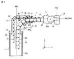
- FIG. 1 is an external perspective view of a robot arm mechanism of the robot apparatus according to the present embodiment.
- FIG. 2 is a side view showing the internal structure of the robot arm mechanism of FIG.
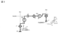
- FIG. 3 is a diagram showing the configuration of the robot arm mechanism of FIG.
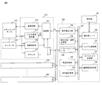
- FIG. 4 is a block diagram showing the configuration of the robot apparatus according to this embodiment.
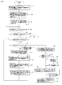
- FIG. 5 is a flowchart showing a processing procedure at the time of step-out by the operation control apparatus of FIG.
- FIG. 6 is a diagram showing a plurality of tracks after the step-out in FIG.
- FIG. 7 is a flowchart showing the procedure of step S13 in FIG.
- the robot apparatus according to this embodiment includes an operation control apparatus.
- the motion control device functions as a single device that controls the motor driver of each joint of the multi-joint arm mechanism provided in the robot device.
- the motion control device can also be incorporated in a robot device having an articulated arm mechanism.
- the motion control device of the robot apparatus according to the present embodiment can be applied to various types of articulated arm mechanisms.
- a multi-joint arm mechanism in which one of the plurality of joints is a linear motion expansion / contraction joint will be described as an example.
- components having substantially the same function and configuration are denoted by the same reference numerals, and redundant description will be given only when necessary.
- FIG. 1 is an external perspective view of a bot arm mechanism according to the present embodiment.
- the robot arm mechanism includes a substantially cylindrical base 10, an arm 2 connected to the base 10, and a wrist 4 attached to the tip of the arm 2.
- the wrist part 4 is provided with an adapter (not shown).
- the adapter is provided in a rotating portion of a sixth rotating shaft RA6 described later.
- a robot hand corresponding to the application is attached to the adapter provided on the wrist portion 4.
- the robot arm mechanism has a plurality of, here, six joint portions J1, J2, J3, J4, J5, and J6.
- the plurality of joint portions J1, J2, J3, J4, J5, and J6 are sequentially arranged from the base portion 10.
- the first, second, and third joints J1, J2, and J3 are called the root three axes
- the fourth, fifth, and sixth joints J4, J5, and J6 change the posture of the robot hand.
- the wrist 4 has fourth, fifth, and sixth joints J4, J5, and J6.
- At least one of the joint portions J1, J2, and J3 constituting the base three axes is a linear motion expansion / contraction joint.
- the third joint portion J3 is configured as a linear motion expansion / contraction joint portion, particularly a joint portion having a relatively long expansion / contraction distance.
- the arm part 2 represents the expansion / contraction part of the linear motion expansion / contraction joint part J3 (third joint part J3).
- the first joint portion J1 is a torsion joint centered on the first rotation axis RA1 supported, for example, perpendicularly to the base surface.
- the second joint portion J2 is a bending joint centered on the second rotation axis RA2 arranged perpendicular to the first rotation axis RA1.
- the third joint portion J3 is a joint in which the arm portion 2 expands and contracts linearly around a third axis (moving axis) RA3 arranged perpendicular to the second rotation axis RA2.
- the fourth joint portion J4 is a torsion joint centered on the fourth rotation axis RA4.
- the fourth rotation axis RA4 substantially coincides with the third movement axis RA3 when a later-described seventh joint portion J7 is not rotating, that is, when the entire arm portion 2 is linear.
- the fifth joint J5 is a bending joint centered on a fifth rotation axis RA5 orthogonal to the fourth rotation axis RA4.
- the sixth joint portion J6 is a bending joint centered on the sixth rotation axis RA6 that is perpendicular to the fourth rotation axis RA4 and perpendicular to the fifth rotation axis RA5.
- the arm support (first support) 11a forming the base 10 has a cylindrical hollow structure formed around the first rotation axis RA1 of the first joint J1.
- the first joint portion J1 is attached to a fixed base (not shown).
- the arm portion 2 pivots left and right along with the shaft rotation of the first support 11a.
- the first support 11a may be fixed to the ground plane.
- the arm part 2 is provided in a structure that turns independently of the first support 11a.
- a second support part 11b is connected to the upper part of the first support 11a.
- the second support portion 11b has a hollow structure that is continuous with the first support portion 11a.
- One end of the second support portion 11b is attached to the rotating portion of the first joint portion J1.
- the other end of the second support portion 11b is opened, and the third support portion 11c is fitted so as to be rotatable on the second rotation axis RA2 of the second joint portion J2.
- the 3rd support part 11c has a hollow structure which consists of a scale-like exterior which is connected to the 1st support part 11a and the 2nd support part.
- the third support portion 11c is accommodated in the second support portion 11b and sent out as the second joint portion J2 is bent and rotated.
- the rear part of the arm part 2 that constitutes the linear motion expansion / contraction joint part J3 (third joint part J3) of the robot arm mechanism is housed in the hollow structure in which the first support part 11a and the second support part 11b are continuous by contraction.
- the third support portion 11c is fitted to the lower end portion of the second support portion 11b so as to be rotatable about the second rotation axis RA2 at the lower end portion of the second support portion 11b.
- a second joint portion J2 as a bending joint portion around the second rotation axis RA2 is configured.
- the arm portion 2 rotates in a vertical direction around the second rotation axis RA2, that is, performs a undulation operation.
- the fourth joint portion J4 is a torsional joint having a fourth rotation axis RA4 that is typically in contact with the arm central axis along the expansion / contraction direction of the arm portion 2, that is, the third movement axis RA3 of the third joint portion J3.
- the fifth joint J5 is a bending joint having a fifth rotation axis RA5 orthogonal to the fourth rotation axis RA4 of the fourth joint J4.
- the sixth joint J6 is a bending joint having a sixth rotation axis RA6 perpendicular to the fourth rotation axis RA4 of the fourth joint J4 and perpendicular to the fifth rotation axis RA5 of the fifth joint J5.
- the robot hand turns left and right.
- the robot hand attached to the adapter of the wrist part 4 has the first, second and third joint parts J1. J2. It is moved to an arbitrary position by J3, and is arranged in an arbitrary posture by the fourth, fifth, and sixth joint portions J4, J5, and J6.
- the length of the extension / contraction distance of the arm portion 2 of the third joint portion J3 enables the robot hand to reach a wide range of objects from the proximity position of the base portion 10 to the remote position.
- the third joint portion J3 is characterized by a linear expansion / contraction operation realized by a linear motion expansion / contraction mechanism constituting the third joint portion J3 and a length of the expansion / contraction distance.
- FIG. FIG. 2 is a perspective view showing the internal structure of the robot arm mechanism of FIG.
- the linear motion expansion / contraction mechanism has an arm part 2 and an injection part 30.
- the arm unit 2 includes a first connection frame row 21 and a second connection frame row 22.
- the first connected frame row 21 includes a plurality of first connected frames 23.
- the first connection piece 23 is formed in a substantially flat plate shape.
- the front and rear first connecting pieces 23 are connected in a row so as to be freely bent by pins at the end portions of each other.
- column 21 can be bent freely inside and outside.
- the second linked frame row 22 includes a plurality of second linked frames 24.
- the second connecting piece 24 is configured as a short groove having a U-shaped cross section.
- the front and rear second connecting pieces 24 are connected in a row so as to be freely bent by pins at the bottom end portions of each other.
- the second connecting frame row 22 can be bent inward. Since the cross section of the second connecting piece 24 is U-shaped, the second connecting piece row 22 does not bend outward because the side plates of the adjacent second connecting pieces 24 collide with each other.
- the surfaces of the first and second connecting pieces 23 and 24 facing the second rotation axis RA2 are referred to as inner surfaces, and the opposite surfaces are referred to as outer surfaces.
- the first first linked frame 23 in the first linked frame sequence 21 and the first second linked frame 24 in the second linked frame sequence 22 are connected by a linked frame 27.
- the connecting piece 27 has a shape in which the second connecting piece 24 and the first connecting piece 23 are combined.
- the injection unit 30 includes a plurality of upper rollers 31 and a plurality of lower rollers 32 supported by a rectangular tube-shaped frame 35.
- the plurality of upper rollers 31 are arranged along the arm central axis at an interval substantially equal to the length of the first connecting piece 23.
- the plurality of lower rollers 32 are arranged along the arm central axis at an interval substantially equivalent to the length of the second connecting piece 24.
- a guide roller 40 and a drive gear 50 are provided behind the injection unit 30 so as to face each other with the first connecting piece row 21 interposed therebetween.
- the drive gear 50 is connected to the stepping motor 330 via a speed reducer (not shown).
- a linear gear is formed on the inner surface of the first connecting piece 23 along the connecting direction.
- the linear gears are connected in a straight line to form a long linear gear.
- the drive gear 50 is meshed with a linear linear gear.
- the linear gear connected in a straight line forms a rack and pinion mechanism together with the drive gear 50.
- the injection unit 30 joins the first and second connecting frame rows 21 and 22 to form a columnar body, and supports the columnar body vertically and horizontally.
- the columnar body formed by joining the first and second connecting piece rows 21 and 22 is firmly held by the injection unit 30, so that the joining state of the first and second connecting piece rows 21 and 22 is maintained.
- the bending of the first and second connection frame rows 21 and 22 is constrained to each other.
- columns 21 and 22 comprise the columnar body provided with fixed rigidity.
- the columnar body refers to a columnar rod body in which the first connection frame row 21 is joined to the second connection frame row 22.
- the second connecting piece 24 and the first connecting piece 23 are formed into cylindrical bodies having various cross-sectional shapes as a whole.
- the cylindrical body is defined as a shape in which the top, bottom, left and right are surrounded by a top plate, a bottom plate, and both side plates, and the front end and the rear end are open.
- the columnar body formed by joining the first and second connecting piece rows 21 and 22 starts from the connecting piece 27 and linearly extends from the opening of the third support portion 11c along the third movement axis RA3. Sent out.
- the first connecting piece row 21 engaged with the drive gear 50 is pulled back into the first support 11a.
- the columnar body is pulled back into the third support body 11c with the movement of the first connection frame row.
- the columnar body pulled back is separated behind the injection unit 30.
- the first connecting piece row 21 constituting the columnar body is sandwiched between the guide roller 40 and the drive gear 50, and the second connecting piece row 22 constituting the columnar body is pulled downward by gravity, whereby the second connecting piece row 22 is drawn.
- the frame row 22 and the first linked frame row 21 are separated from each other.
- the separated first and second connecting frame rows 21 and 22 are returned to a bendable state, bent inward in the same direction, and stored substantially in parallel inside the first support 11a.
- FIG. 3 is a diagram showing the robot arm mechanism of FIG.
- three position degrees of freedom are realized by the first joint portion J1, the second joint portion J2, and the third joint portion J3 that form the three base axes.
- three posture degrees of freedom are realized by the fourth joint portion J4, the fifth joint portion J5, and the sixth joint portion J6 constituting the wrist three axes.
- the robot coordinate system ⁇ b is a coordinate system having an arbitrary position on the first rotation axis RA1 of the first joint portion J1 as an origin.
- three orthogonal axes (Xb, Yb, Zb) are defined.
- the Zb axis is an axis parallel to the first rotation axis RA1.
- the Xb axis and the Yb axis are orthogonal to each other and orthogonal to the Zb axis.
- the hand coordinate system ⁇ h is a coordinate system having an arbitrary position (hand reference point) of the robot hand 5 attached to the wrist 4 as an origin.
- the position of the hand reference point (hereinafter simply referred to as the hand) is defined as the center position between the two fingers.
- the hand coordinate system ⁇ h three orthogonal axes (Xh, Yh, Zh) are defined.
- the Zh axis is an axis parallel to the sixth rotation axis RA6.
- the Xh axis and the Yh axis are orthogonal to each other and orthogonal to the Zh axis.
- the Xh axis is an axis parallel to the front-rear direction of the robot hand 5.
- the hand posture is a rotation angle around each of three orthogonal axes of the hand coordinate system ⁇ h with respect to the robot coordinate system ⁇ b (rotation angle around the Xh axis (yaw angle) ⁇ , rotation angle around the Yh axis (pitch angle) ⁇ , Zh axis It is given as the surrounding rotation angle (roll angle) ⁇ .
- 1st joint part J1 is arrange
- the rotation axis RA1 is arranged perpendicular to the reference plane BP of the base on which the fixing portion of the first joint portion J1 is installed.
- 2nd joint part J2 is comprised as a bending joint centering on rotating shaft RA2.
- the rotation axis RA2 of the second joint portion J2 is provided in parallel to the Xb axis on the spatial coordinate system.
- the rotation axis RA2 of the second joint portion J2 is provided in a direction perpendicular to the rotation axis RA1 of the first joint portion J1.
- the second joint portion J2 is offset with respect to the first joint portion J1 in two directions, that is, the direction of the first rotation axis RA1 (Zb axis direction) and the Yb axis direction perpendicular to the first rotation axis RA1.
- the second support 11b is attached to the first support 11a so that the second joint J2 is offset in the two directions with respect to the first joint J1.
- a virtual arm rod portion (link portion) that connects the second joint portion J2 to the first joint portion J1 has a crank shape in which two hook-shaped bodies whose tips are bent at right angles are combined.
- This virtual arm rod part is comprised by the 1st, 2nd support bodies 11a and 11b which have a hollow structure.
- 3rd joint part J3 is comprised as a linear motion expansion-contraction joint centering on movement axis RA3.
- the movement axis RA3 of the third joint portion J3 is provided in a direction perpendicular to the rotation axis RA2 of the second joint portion J2.
- the movement axis RA3 of the third joint portion J3 is the second joint
- the rotation axis RA2 of the part J2 and the rotation axis RA1 of the first joint part J1 are provided in a direction perpendicular to the rotation axis RA2.
- the movement axis RA3 of the third joint portion J3 is provided in parallel to the Yb axis perpendicular to the Xb axis and the Zb axis. Further, the third joint portion J3 is offset with respect to the second joint portion J2 in two directions, that is, the direction of the rotation axis RA2 (Yb axis direction) and the direction of the Zb axis orthogonal to the movement axis RA3.
- the third support 11c is attached to the second support 11b so that the third joint J3 is offset in the two directions with respect to the second joint J2.
- the virtual arm rod portion (link portion) that connects the third joint portion J3 to the second joint portion J2 has a hook-shaped body whose tip is bent vertically. This virtual arm rod portion is constituted by the second and third supports 11b and 11c.
- the fourth joint portion J4 is configured as a torsion joint with the rotation axis RA4 as the center.
- the rotation axis RA4 of the fourth joint part J4 is arranged to substantially coincide with the movement axis RA3 of the third joint part J3.
- the fifth joint J5 is configured as a bending joint with the rotation axis RA5 as the center.
- the rotation axis RA5 of the fifth joint portion J5 is disposed so as to be substantially orthogonal to the movement axis RA3 of the third joint portion J3 and the rotation axis RA4 of the fourth joint portion J4.
- the sixth joint portion J6 is configured as a torsion joint with the rotation axis RA6 as the center.
- the rotation axis RA6 of the sixth joint portion J6 is disposed so as to be substantially orthogonal to the rotation axis RA4 of the fourth joint portion J4 and the rotation axis RA5 of the fifth joint portion J5.
- the sixth joint J6 is provided to turn the robot hand 5 as a hand effector left and right.
- the sixth joint portion J6 may be configured as a bending joint whose rotation axis RA6 is substantially orthogonal to the rotation axis RA4 of the fourth joint portion J4 and the rotation axis RA5 of the fifth joint portion J5.
- one bending joint portion of the base three axes of the plurality of joint portions J1-J6 is replaced with a linear motion expansion / contraction joint portion, and the second joint portion J2 is offset in two directions with respect to the first joint portion J1.
- the robot arm mechanism of the robot apparatus according to the present embodiment eliminates the singularity posture structurally.
- FIG. FIG. 4 is a block diagram showing the configuration of the robot apparatus according to this embodiment.
- Stepping motors 310, 320, 330, 340, 350, and 360 are provided as actuators at joints J1, J2, J3, J4, J5, and J6 of the robot arm mechanism of the robot apparatus according to the present embodiment, respectively.
- Driver units 210, 220, 230, 240, 250, and 260 are electrically connected to the stepping motors 310, 320, 330, 340, 350, and 360.
- the driver units 210, 220, 230, 240, 250, and 260 are provided alongside the stepping motors 310, 320, 330, 340, 350, and 360 to be controlled.
- driver units 210, 220, 230, 240, 250, 260 have the same configuration, and perform the same operation on the stepping motor to be controlled according to the control signal from the operation control device 100.
- driver unit 210 will be described, and description of the other driver units 220, 230, 240, 250, and 260 will be omitted.
- the driver unit 210 controls the driving and stopping of the stepping motor 310.
- the driver unit 210 includes a control unit 211, a power supply circuit 212, a pulse signal generation unit 213, a rotary encoder 215, a step-out determination unit 216, and a counter 217.
- the control unit 211 controls the driver unit 210 in an integrated manner according to a control signal input from the operation control apparatus 100.
- control unit 211 in the driver unit 210 relates to a target position after the unit time ⁇ t of the rotation angle of the stepping motor 310 from the operation control device 100 (distinguished from a final target position described later).
- a position command signal is input.
- the control signal is given as a joint variable after ⁇ t (joint angle, expansion / contraction distance in J3).
- the control unit 211 determines the number of pulses Np based on the current position of the rotation angle of the stepping motor 310 and the target position.
- the control unit 211 calculates a rotation angle difference based on the current position of the rotation angle of the stepping motor 310 and the target position, and calculates the rotation angle difference between the current position and the target position of the stepping motor 310, for example, 0.
- the pulse number Np of the pulse signal is determined by dividing by a step angle of 72 degrees.
- the control unit 211 determines the pulse frequency fp based on the determined number of pulses and the unit time ⁇ t. Specifically, the control unit 211 determines the pulse frequency fp by multiplying the unit time ⁇ t by the pulse number Np and calculating the reciprocal thereof.
- the control unit 211 outputs a pulse number command signal related to the number of pulses and a pulse frequency command signal related to the pulse frequency to the pulse signal generation unit 213.
- the pulse signal generator 213 outputs a pulse signal having the number of pulses commanded by the pulse number command signal to each phase of the stepping motor 310 at a frequency commanded by the pulse frequency command signal, that is, a cycle of the reciprocal of the frequency.
- the pulse signal output from the pulse signal generation unit 213 is also taken into a step-out determination unit 216 described later.
- the controller 211 receives a drive current command signal that represents the drive current value of the stepping motor 310 from the operation control device 100.
- the control unit 211 outputs a control signal corresponding to the drive current command signal to the power supply circuit 212.
- the power supply circuit 212 generates a drive current having a designated drive current value using electric power supplied from an external power supply unit (not shown). The generated drive current is supplied to the stepping motor 310.
- the stepping motor 310 is driven by the drive current supplied from the power supply circuit 212 and is rotated according to the pulse signal output from the pulse signal generator 213.
- the rotary encoder 215 is connected to the drive shaft of the stepping motor 310 and outputs a pulse signal (encoder pulse) at a constant rotation angle of, for example, 0.18 degrees.
- the counter 217 calculates the count number by adding or subtracting the number of encoder pulses output from the rotary encoder 215 according to the rotation direction. This count number is reset at the reference position (origin) of the drive shaft of the stepping motor 310.
- the joint angle (joint variable) of the joint is obtained from the number of resets and the count.
- the step-out determination unit 216 determines whether the stepping motor 310 has stepped out or has stepped out by comparing the number of encoder pulses counted with respect to the pulse signal output from the pulse signal generation unit 213. .
- the step-out determination unit 216 repeats counting / resetting the encoder pulse in synchronization with the pulse signal.
- the step angle that rotates in one cycle of the pulse signal is fixed.
- the number of encoder pulses corresponding to the step angle is fixed. If the count number of the encoder pulse matches the number corresponding to the step angle, the rotation of the stepping motor 310 is synchronized with the pulse signal, that is, no step-out has occurred.
- the step out determination unit 216 generates a step out detection signal.
- the motion control apparatus 100 includes a system control unit 101, an operation unit interface 102, a command value output unit 103, a current position / attitude calculation unit 104, a trajectory calculation unit 105, a command value calculation unit 106, and a dynamics calculation unit. 107, a drive current determination unit 108, and a driver unit interface 109. From the driver unit 210, the operation control device 100 outputs the count number (representing the rotation angle from the reference position) counted by the counter 217 and the number of resets (representing the number of rotations) and the step-out determination unit 216. The step-out detection signal is input via the driver unit interface 109.
- the robot apparatus motion control apparatus 100 according to the present embodiment can be applied as an independent apparatus to other apparatuses and mechanisms that use a stepping motor.
- the system control unit 101 includes a CPU (Central Processing Unit), a semiconductor memory, and the like, and controls the operation control apparatus 100 in an integrated manner. Each unit is connected to the system control unit 101 via a control / data bus 110.
- CPU Central Processing Unit
- semiconductor memory and the like
- An operation unit 50 is connected to the operation control apparatus 100 via an operation unit interface 102.
- the operation unit 50 functions as an input interface for the user to input a change in the position of the point of interest of the wrist 4 or the robot hand (hand effector), a change in posture, and a change time.
- the motion control apparatus 100 executes calculation processing such as movement / posture change using, for example, the tip of a two-finger hand as a point of interest (control point).
- the operation unit 50 includes a joystick or the like for designating a final target position for moving the robot hand and a moving time.
- the final target position and movement time of the robot hand are input based on the direction in which the joystick is operated, the angle at which the joystick is tilted, and the operation acceleration of the joystick.
- these input devices constituting the operation unit 50 can be replaced with other devices such as a mouse, a keyboard, a trackball, and a touch panel.
- the command value output unit 103 outputs the command value (joint angle after ⁇ t (joint variable)) for each joint portion J1-J6 calculated by the command value calculation unit 106, which will be described later, under the control of the system control unit 101. Output to 210, 220, 230, 240, 250, 260. Specifically, the command value output unit 103 sends position command signals corresponding to the joint variables for the joints J1-J6 calculated by the command value calculation unit 106, which will be described later, to the driver units 210, 220, 230, 240, 250. , 260 are output.
- command value output unit 103 outputs a drive current command signal corresponding to the drive current value for driving each of the joints J1-J6 determined by the drive current determination unit 108, which will be described later, to the driver units 210, 220, 230, 240, It outputs to 250,260.
- the current position / posture calculation unit 104 performs forward kinematics based on the joint transformation matrix defined according to the link parameters of the arm structure based on the joint variables of the joints J1, J2, J3, J4, J5, and J6.
- the position and orientation of the point of interest of the hand as seen from the robot coordinate system are calculated.
- the joint variable is a positive or negative rotation angle from the reference position in the joint portions J1, J2, J4, J5, and J6, and in the joint portion J3, the extension distance (linear displacement) from the most contracted state. .
- Joint variable vector for the joints J1-J6 - calculate the ⁇ .
- Joint variable vector - theta is given by a rotating joint J1, J2, J4, J5, J6 of joint angle ⁇ J1, ⁇ J2, ⁇ J4 , ⁇ J5, ⁇ J6 and telescopic length L J3 of linear expansion joints J3 Is a set of joint variables ( ⁇ J1 , ⁇ J2 , L J3 , ⁇ J4 , ⁇ J5 , ⁇ J6 ).
- the current position / posture calculation unit 104 holds the cumulative count number before starting the stepping motor 310 of the joint portion J1, and adds the count number counted during the startup to the cumulative count number. Update the number.
- the current position / posture calculation unit 104 calculates the rotation angle from the reference position of the stepping motor 310 by multiplying the accumulated count by a step angle corresponding to 1 count, and specifies the joint variable of the joint portion J1.
- the current position / posture calculation unit 104 identifies the joint variables of the other joints J2-J6 by the same method.
- the current position / attitude calculation unit 104 uses the homogeneous transformation matrix K (parameters ( ⁇ J1 , ⁇ J2 , L J3 , ⁇ J4 , ⁇ J5 , ⁇ J6 )) to determine the position of the point of interest of the hand as viewed from the robot coordinate system ⁇ b. Calculate (x, y, z) and hand posture ( ⁇ , ⁇ , ⁇ ).
- the homogeneous transformation matrix K is a determinant that defines the relationship between the hand coordinate system ⁇ h and the robot coordinate system ⁇ b.
- the homogeneous transformation matrix K is determined by the relationship between the links constituting the robot arm mechanism (link length and link twist angle) and the relationship between the joint axes (distance between links and angle between links).
- current position and orientation calculation unit 104 the joint variable vector of the current robot arm mechanism - ⁇ 0 ( ⁇ 0-J1 , ⁇ 0-J2, L 0-J3, ⁇ 0-J4, ⁇ 0-J5, ⁇
- the current position P0 x 0 , y 0 , z 0
- the hand posture ⁇ 0 ⁇ 0 , ⁇ 0 , ⁇ 0 .
- the trajectory calculation unit 105 calculates a point sequence of the target position of the hand for each unit time ⁇ t (control cycle, for example, 10 ms) connecting between the current position / posture of the hand and the final target position / posture of the hand. To do.
- the current position / posture of the hand is obtained from calculation processing by the current position / posture calculation unit 104.
- the final target position / posture of the hand and the movement time are input by the user via the operation unit 50, for example.
- the trajectory calculation unit 105 substitutes each parameter into a preset function that has the current position and current posture of the hand and the final target position and final target posture of the hand as parameters.
- a target position per unit time ⁇ t is calculated on the hand trajectory.
- An arbitrary method is adopted as the trajectory calculation method.
- the unit time ⁇ t is a fixed value as the control cycle, and is set to 10 ms by the user, for example.
- the target position is a parameter that gives both the position and posture of the hand.
- the trajectory calculation unit 105 can recalculate five types of trajectories under the control of the system control unit 101 when a step-out is detected.
- the first to third trajectories are trajectories from the position of the point of interest of the hand shifted from the original trajectory due to the step-out (movement restart position) to the final target position through different paths.
- the fourth and fifth trajectories are trajectories that return from the movement resumption position to a position at the start of movement through different paths.
- one of the five tracks is selected, and movement control is performed along the track.
- the trajectory calculation method is arbitrary, and a plurality of functions may be preset.
- the trajectory calculation unit 105 changes the function used for the calculation of the hand trajectory according to the control of the system control unit 101.
- the trajectory calculation unit 105 recalculates the hand trajectory after the step-out detection using a function different from the function used for the normal hand trajectory calculation.
- the hand trajectory calculated again after the step-out detection is equivalent to the shortest path connecting the position P0 ′ after the step-out detection and the final target position P1.
- the hand trajectory calculated again after the step-out detection has a trajectory in which the hand is pulled back by a predetermined distance from the position after the escape detection to the position at the time of the step-out detection.
- the command value calculation unit 106 calculates a plurality of joint variable vectors respectively corresponding to the target positions arranged on the calculated trajectory with a period of ⁇ t.
- the joint variable vector refers to six variables of the joint portions J1-J6, that is, six variables of the rotation angles of the rotary joint portions J1, J2, J4-J6 and the arm expansion / contraction length of the linear motion expansion / contraction joint portion J3. The calculation process of the command value calculation unit 106 will be described later.
- the dynamics calculation unit 107 includes torques (drive torques) of the respective stepping motors 310 to 360 provided at the joints J1 to J6 that are required to move the hand from the target position to the next target position after ⁇ t. Calculate Further, the dynamics calculation unit 107 calculates a torque (static torque) required for each joint unit to make the arm unit 2 stationary.
- the static torque required for each joint is equivalent to the load torque related to the joint calculated in the opposite direction to the mass of the center of gravity of the portion ahead of the joint, the distance from the rotation axis of the joint to the center of gravity, etc. Torque, that is, torque that balances the load torque due to its own weight.
- the required torque of each of the stepping motors 310 to 360 uses the dynamics model data related to the joint portion J1-J6, and the center of gravity position, the center-of-gravity mass, the link length, the inertia tensor of each link connecting the joint portion J1-J6 of the robot arm mechanism, It is calculated from joint variables (rotational angle position or linear motion displacement), joint angular velocity, joint angular acceleration, etc. of the joint.
- the dynamics model refers to a model related to motor dynamic characteristics.
- the drive current determination unit 108 determines the drive current values of the stepping motors 310, 320, 330, 340, 350, and 360 in order to generate the torque calculated by the dynamics calculation unit 107.
- the drive current determination unit 108 holds data of a correspondence table in which the magnitude of torque and the drive current value of each of the stepping motors 310, 320, 330, 340, 350, and 360 are associated with each other.
- the drive current determination unit 108 refers to the correspondence table and determines a drive current value corresponding to the magnitude of each of the joints J1 to J6 calculated by the dynamics calculation unit 107.
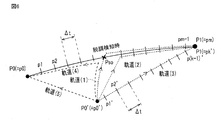
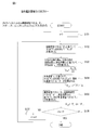
- FIGS. 5 and 6 are diagrams showing the first to fifth trajectories (1) to (5). Each unit of the operation control apparatus 100 is operated according to the flowchart of FIG.
- Step S11 Input of final target position, etc.
- the final target position of the point of interest of the hand is input via the operation unit interface 102.
- the final target position P1 is input.
- a waiting time tw from the step out to the movement resumption is set.
- the standby time tw can be set to 0 or more. The fact that the waiting time tw is set to 0 hours naturally means that the resumption of movement is permitted immediately.
- Step S12 Calculation process of hand trajectory
- the trajectory calculation unit 105 calculates the hand trajectory from the current position (movement start position) of the hand point of interest to the final target position input in step S11.
- the trajectory calculation unit 105 sets a plurality of target positions per unit time ⁇ t on the hand trajectory from the current position of the hand focus point to the final target position.
- the current position P 0 of the hand point of interest is obtained from calculation processing by the current position / posture calculation unit 104.
- the current position and orientation calculation unit 104 based on the count number counted by the driver unit 210,220,230,240,250,260 each counter 217, the current joint variable vector - theta 0 ( ⁇ 0-J1 , ⁇ 0-J2 , L 0-J3 , ⁇ 0-J4 , ⁇ 0-J5 , ⁇ 0-J6 ) are calculated and based on the joint variable vector ⁇ ⁇ 0 Is calculated.
- Step S13 Calculation processing of command value (joint variable vector) of joint portion J1-J6
- the command value calculation unit 106 calculates a plurality of joint variable vectors representing the angles and extension distances of the joints respectively corresponding to the plurality of target positions calculated in step S12.
- Step S14 Command Value Output Processing
- the position command signal corresponding to the joint variable vector calculated in step S13 and the drive current command signal corresponding to the drive current value determined by the drive current determination unit 108 are the command values.
- the output unit 103 sequentially outputs the driver units 210, 220, 230, 240, 250, and 260 at a predetermined control cycle ⁇ t (for example, 10 ms).
- ⁇ t for example, 10 ms
- Step S15 Judgment processing of whether the hand has reached the final target position
- the system control unit 101 determines whether the hand has reached the final target position. Specifically, the current position / attitude calculation unit 104 compares the current position of the hand calculated for each control cycle ⁇ t with the final target position P1 shown in FIG. When the current position of the hand matches the final target position, it is determined that the hand has reached the final target position. At this time, a series of control by the operation control apparatus 100 is completed. On the other hand, when the current position of the hand does not match the final target position of the hand, the process proceeds to step S16.
- Step S16 Judgment processing for occurrence of step-out
- the system control unit 101 determines whether or not a step-out has occurred. Specifically, when a step-out detection signal is input from the step-out determination unit 216 to the operation control apparatus 100, the process proceeds to step S17.
- the position of the hand at the time of step-out detection is Pso, and some external cause, for example, the operator touches the arm part 2 of the robot arm mechanism, and the hand is moved to the position P0 ′. .
- the position command signal and the drive current command signal have a predetermined control cycle ⁇ t until the current position of the hand reaches the final target position of the hand. Are output sequentially.
- Step S17 Recalculation processing of hand trajectory at the time of occurrence of step-out
- the system control unit 101 maintains the initial final target position P1 as the arrival position when the hand movement is resumed after the step-out detection, or the position P0 at the start of movement from the initial final target position P1.
- the distance ⁇ d shifted by step-out that is, the distance (shift distance) ⁇ d between the hand position Pso at the time of step-out detection on the initial trajectory and the hand position P0 ′ shifted after the step-out occurs.
- the operation control unit 100 controls the driver unit 210 to repeatedly output a command value for resuming movement, and retry movement resumption. Let this repetition period (retry period) be ⁇ t1, and the number of repetitions (retry number) be n.
- the state in which the number of pulse signals from the pulse signal generation unit 213 matches the number of encoded pulses is a state in which step-out has been eliminated, and movement can be resumed in that state.
- the retry control for resuming movement is repeated until this state is achieved.
- step S17 the position of the hand does not significantly deviate from the original trajectory due to the step-out (the shift distance ⁇ d is relatively short), and a long time elapses until the step-out occurs and is resolved. If it is not (downtime n ⁇ ⁇ t1 is relatively short), the movement is resumed and the initial final target position is aimed at, while the hand position greatly deviates from the original trajectory due to the step-out, ( When the shift distance [Delta] d is relatively long) and / or when a long time has passed after the occurrence of the step-out and it is resolved (downtime n. [Delta] t1 is relatively long), the initial final target position is set. It is released, returns to the movement start position, and waits for the next task.
- the threshold value THd compared with the shift distance ⁇ d to determine the length of the shift distance ⁇ d and the downtime (n ⁇ ⁇ t1) to determine the length of the downtime (n ⁇ ⁇ t1).
- the threshold value THt is dynamically changed by the system control unit 101. For example, a relatively small value is set when the position Pso at the time of step-out detection is closer to the movement start position P0 than the final target position P1, and a comparison is made when the position Pso at the time of step-out detection is closer to the final target position P1 than the movement start position P0. Is set to a large value.
- step S18 the system control unit 101 waits for the movement to be resumed until a movement resumption instruction is input by the operator. To do. Or when the manual instruction
- step S19 When a movement resumption instruction is input by the operator in step S18 or when the standby time tw has elapsed, a command value is output according to the trajectory selected in steps S19 to S21, and movement is resumed.
- the trajectory recalculation step S19 and the trajectory selection step S20 are executed in parallel with the step S18.
- step S19 the three types of trajectories (1) to (3) shown in FIG.
- the first trajectory (1) is out of step from the initial trajectory from the movement start position P0 to the final target position P1 from the position of the point of interest of the hand shifted due to the out-of-step (position when resuming movement) P0 '.
- This is a trajectory that follows a path deviated due to the above, returns to the out-of-step detection position Pso on the original trajectory, and reaches the final target position along the initial trajectory.
- the second trajectory (2) is a position between the position Pso 'at the time of step-out detection and the final target position P1 from the position of the point of interest of the hand shifted due to the step-out (position at the time of resuming movement) P0'. Is a trajectory that reaches the final target position along the initial trajectory.
- the third trajectory (3) is the shortest linear trajectory from the position P0 'of the target point shifted due to the step-out to the final target position P1.
- step S20 one of the three types of trajectories (1) to (3) is selected by the trajectory calculation unit 105 or the system control unit 101.
- the first orbit (1) has the first priority
- the second orbit (2) has the second priority
- the third orbit (3) has the third priority.
- the task time that is originally set for the movement from the initial movement start position P0 to the final target position P1 is less than the predetermined upper speed limit for the movement speed of the point of interest. Can be maintained within or not. If the first track (1) that has the longest track length and is assumed to have the highest safety satisfies the selection condition, the first track (1) is selected.
- the second trajectory (2) is selected.
- the third trajectory (3) Is selected. Note that the operation when the third trajectory (3) does not satisfy the selection condition is arbitrarily set, and may typically remain at the movement resumption position P0 ′, or the fourth trajectory (4 ) May be selected to return to the movement start position P0 and wait for the next task.
- command values representing a plurality of joint variable vectors respectively corresponding to a plurality of target positions on the trajectory selected in step S20 are calculated by the command value calculation unit 106, and sequentially in a cycle of a predetermined control cycle ⁇ t.
- step S17 If “NO” in the step S17, that is, if it is determined that the movement is resumed and the return trajectory (4) or (5) is followed to return to the original movement start position P0, the system control is performed in the step S22.
- the unit 101 waits for resumption of movement until an instruction for resuming movement by the operator is input, or waits for the elapse of the standby time tw set in step S11 from the time of step-out detection.
- step S23 When a movement resumption instruction is input by the operator in step S22 or when the standby time tw has elapsed, in step S23, the “return trajectory (4), (5) returning to the movement start position P0 set in step S11”.
- Manual selection function is set to OFF, in step S24, the trajectory calculation unit 105 determines from the position of the point of interest of the hand shifted due to the step-out (position when resuming movement) P0 ′. A return trajectory (4) returning to the original movement start position P0 is calculated.
- the return trajectory (4) returns to the out-of-step detection position Pso from the position P0 'at the time of resuming the movement, following a path deviated from the initial trajectory from the movement start position P0 to the final target position P1 due to the out-of-step. This is a trajectory going back to the original movement start position P0 from the original trajectory.
- the fifth trajectory (5) is a linear shortest return trajectory from the position of the point of interest (movement restart position) P0 'shifted due to the step-out to the original movement start position P0.
- the return trajectory (4) is the path that has just passed, it can be said that the possibility of an obstacle or the like intervening on the trajectory is lower than that of the new fifth trajectory (5), that is, the safety is high. Therefore, when the operator does not manually select the trajectory, the return trajectory (4) is preferentially selected as the return trajectory (5).
- step 25 a command value representing a plurality of joint variable vectors respectively corresponding to a plurality of target positions on the trajectory (4) calculated in step S24 is calculated by the command value calculation unit 106, and a predetermined control cycle ⁇ t.
- the command value is output from the command value output unit 103 to the driver units 210, 220, 230, 240, 250, and 260 together with the command signal representing the drive current value at each position determined by the drive current determination unit 108 in order in a cycle. .
- step S23 when the “manual selection function of the return trajectory (4), (5) returning to the movement start position P0)” set in step S11 is set to ON, in step S26, the operation is performed by the system control unit 101.
- a screen for prompting the operator to select either the return trajectory (4) or the fifth trajectory (5) is displayed on the display of the unit 50.
- the process proceeds to step S24.
- the trajectory calculation unit 105 in step S28 performs the original movement from the position of the point of interest of the hand shifted due to the step-out (position when the movement is resumed) P0 '.
- the return trajectory (5) which returns linearly to the start position P0 in the shortest time is calculated, and the process proceeds to step S25.
- steps S14 to S28 are repeated until the point of interest of the hand 5 reaches the final target position P1 or returns to the movement start position P0 through step S15.
- step-out which is a characteristic unique to a stepping motor
- a safety mechanism has been required such as detecting the contact with an acceleration sensor or the like to stop the operation.
- a step-out occurs due to the load, and the operation stops. Therefore, the same safety as in the prior art can be ensured.
- a variable n is used.
- this variable n is initialized to a zero value.
- Jacobian inverse matrix J -1 (- ⁇ n) calculation of The robot arm mechanism of the robot apparatus according to the present embodiment has no singular point due to its structure, and therefore a Jacobian inverse matrix always exists.
- the Jacobian inverse matrix is a matrix that converts the hand speed (minor change in hand position / posture) to the joint angular velocity (minor change in joint angle / extension / contraction length).
- the Jacobian inverse matrix is given by the knitting differential with the joint variable of the vector representing the hand position / hand posture.
- Step S133 Calculation of hand speed ⁇ pn + 1 Based on the current hand position (current target position) pn, the next hand position (next target position after unit time ⁇ t) pn + 1, and the unit time ⁇ t, the hand speed ⁇ pn + 1 is calculated.
- Step S134 Calculation of Joint Angular Velocity- ⁇ ⁇ n + 1
- the - (.theta.n), joint angular velocity - - calculated hand speed in step S133 pn + 1 is a Jacobian inverse matrix J -1 are converted into ⁇ ⁇ n + 1.
- the displacement amount of each joint during the unit time ⁇ t is calculated.
- Joint variable vector of the moving just before - by adding the displacement amount of the joint .theta.n, joint variable vector after unit time ⁇ t elapses - .theta.n + 1 is calculated.
- Step S136 Determination of processing continuation
- the variable n is the number of repetitions (m ⁇ 1)
- the calculation process by the command value calculation unit 106 is terminated.
- the variable (n) is not the number of repetitions (m ⁇ 1)
- the process proceeds to step S137.
- Step S137 Raise variable n ⁇ n + 1
- the variable n is incremented to (n + 1), and the process returns to step S142.
- the joint portions J1-J6 constituting the robot arm mechanism are provided with the stepping motors 310 to 360, respectively.
- the operations of these stepping motors 310 to 360 are controlled by the operation control device 100.
- a stepping motor is not generally used for industrial robots because a step-out occurs when a load larger than the torque of the stepping motor is applied to the stepping motor.
- the robot apparatus according to the present embodiment does not have a singular point in structure, and therefore the arm does not perform a large turning movement to avoid the singular point at an unexpected timing.
- it can be used as a co-robot device that performs work. That is, the robot apparatus according to the present embodiment can be arranged close to the worker.
- the stepping motor will step out if a load exceeding the required torque of the stepping motor is applied to the stepping motor. Therefore, the arm does not harm the operator with a large force exceeding the required torque of the stepping motor. Therefore, by using a stepping motor for the actuator of the joint part, the risk of injury of the worker due to the arm coming into contact with the worker can be reduced compared to the case of using another motor, such as an AC motor. it can.
- the post-step-out position may deviate from the planned hand trajectory.
- the trajectory calculation unit 105 of the motion control apparatus 100 of the robot apparatus according to the present embodiment moves from the current position of the hand after the step-out detection to the final target position of the hand.
- the hand trajectory can be calculated again. Therefore, even when a step-out occurs, the hand movement control is continued, and the hand can be moved again from the position after the step-out detection to the final target position.
- the robot apparatus can provide a preferable countermeasure when a step-out occurs on the premise that a step-out occurs in the stepping motor.
- the stepping motor control has been described by taking the robot apparatus as an example.
- the stepping motor can be applied to another operation target, for example, a line movement actuator of the conveyor apparatus, and can be applied to the stepping motor control.
- a process in which the line as the operation target changes (speed change) from the current state (current speed) to the target state (target speed) is calculated, and a command value is output according to the process.
- the stepping motor has stepped out in the process, the process from the line speed at the time of the step-out to the target speed is calculated again, and the line speed is changed stepwise according to the recalculated process.
- Such application is also within the concept of this embodiment.
Landscapes
- Engineering & Computer Science (AREA)
- Robotics (AREA)
- Mechanical Engineering (AREA)
- Human Computer Interaction (AREA)
- Manipulator (AREA)
Priority Applications (3)
| Application Number | Priority Date | Filing Date | Title |
|---|---|---|---|
| CN201680030783.5A CN107614209A (zh) | 2015-05-28 | 2016-05-15 | 机器人装置及步进马达控制装置 |
| EP16799848.3A EP3305478A4 (en) | 2015-05-28 | 2016-05-15 | ROBOT DEVICE AND STEPPER MOTOR CONTROL DEVICE |
| US15/822,313 US20180079077A1 (en) | 2015-05-28 | 2017-11-27 | Robot device and stepping motor control device |
Applications Claiming Priority (2)
| Application Number | Priority Date | Filing Date | Title |
|---|---|---|---|
| JP2015-108688 | 2015-05-28 | ||
| JP2015108688A JP6659238B2 (ja) | 2015-05-28 | 2015-05-28 | ロボット装置及びステッピングモータ制御装置 |
Related Child Applications (1)
| Application Number | Title | Priority Date | Filing Date |
|---|---|---|---|
| US15/822,313 Continuation US20180079077A1 (en) | 2015-05-28 | 2017-11-27 | Robot device and stepping motor control device |
Publications (1)
| Publication Number | Publication Date |
|---|---|
| WO2016190140A1 true WO2016190140A1 (ja) | 2016-12-01 |
Family
ID=57393896
Family Applications (1)
| Application Number | Title | Priority Date | Filing Date |
|---|---|---|---|
| PCT/JP2016/064403 WO2016190140A1 (ja) | 2015-05-28 | 2016-05-15 | ロボット装置及びステッピングモータ制御装置 |
Country Status (6)
Cited By (1)
| Publication number | Priority date | Publication date | Assignee | Title |
|---|---|---|---|---|
| JP2021058987A (ja) * | 2019-10-09 | 2021-04-15 | 川崎重工業株式会社 | 制御方法、制御装置、ロボットシステム及びプログラム |
Families Citing this family (10)
| Publication number | Priority date | Publication date | Assignee | Title |
|---|---|---|---|---|
| JP6468804B2 (ja) * | 2014-10-30 | 2019-02-13 | ライフロボティクス株式会社 | ロボットアーム機構 |
| JP2018051635A (ja) * | 2016-09-26 | 2018-04-05 | セイコーエプソン株式会社 | ロボット制御装置、ロボットおよびロボットシステム |
| JP7007839B2 (ja) * | 2017-08-31 | 2022-01-25 | 川崎重工業株式会社 | 多関節ロボット |
| JP6846717B2 (ja) * | 2018-02-14 | 2021-03-24 | ファナック株式会社 | ロボットのジョイントの異常検出装置及び異常検出方法 |
| JP7310963B2 (ja) * | 2019-03-22 | 2023-07-19 | オムロン株式会社 | ロボットハンド、ロボットハンド制御方法及びプログラム |
| CN109861599B (zh) * | 2019-03-25 | 2021-11-12 | 北京美联泰科生物技术有限公司 | 电机控制方法 |
| EP4013573A1 (en) * | 2019-11-19 | 2022-06-22 | Google LLC | Optimization of motion paths of a robot using vision data |
| US12290932B2 (en) * | 2020-07-10 | 2025-05-06 | Fanuc Corporation | Trajectory generation device and automatic position control device |
| CN113315425B (zh) * | 2021-07-28 | 2021-11-30 | 深圳市永达电子信息股份有限公司 | 步进电机定位方法、系统、设备及存储介质 |
| TWI766807B (zh) * | 2021-09-17 | 2022-06-01 | 財團法人精密機械研究發展中心 | 機械手臂的安全復位方法 |
Citations (4)
| Publication number | Priority date | Publication date | Assignee | Title |
|---|---|---|---|---|
| JPS63206197A (ja) * | 1987-02-20 | 1988-08-25 | Jeol Ltd | ア−ム移動を司どるモ−タの制御機構 |
| JP2000047731A (ja) * | 1998-07-29 | 2000-02-18 | Janome Sewing Mach Co Ltd | スカラロボット |
| JP2013132696A (ja) * | 2011-12-26 | 2013-07-08 | Seiko Epson Corp | アーム制御装置、および、アーム制御方法 |
| WO2016068175A1 (ja) * | 2014-10-31 | 2016-05-06 | ライフロボティクス株式会社 | ロボットアーム機構及びステッピングモータ制御装置 |
Family Cites Families (9)
| Publication number | Priority date | Publication date | Assignee | Title |
|---|---|---|---|---|
| FR2671305B1 (fr) * | 1991-01-09 | 1995-04-07 | Commissariat Energie Atomique | Procede de pilotage d'un bras de robot en definissant des trajets de substitution. |
| US5426722A (en) * | 1993-09-09 | 1995-06-20 | Stratasys, Inc. | Method for optimizing the motion of a multi-axis robot |
| US6212968B1 (en) * | 1998-07-29 | 2001-04-10 | Janome Sewing Machine Co., Ltd, | SCARA robot |
| US6278907B1 (en) * | 1999-11-24 | 2001-08-21 | Xerox Corporation | Apparatus and method of distributing object handling |
| US6871115B2 (en) * | 2002-10-11 | 2005-03-22 | Taiwan Semiconductor Manufacturing Co., Ltd | Method and apparatus for monitoring the operation of a wafer handling robot |
| CA2601886C (en) * | 2005-03-23 | 2013-03-19 | Hurco Companies, Inc. | Method of tolerance-based trajectory planning and control |
| US7706920B2 (en) * | 2007-09-19 | 2010-04-27 | Disney Enterprises, Inc. | Smooth clipping of data streams |
| KR101732902B1 (ko) * | 2010-12-27 | 2017-05-24 | 삼성전자주식회사 | 로봇의 경로 계획 장치 및 그 방법 |
| US8810187B2 (en) * | 2011-08-19 | 2014-08-19 | Oriental Motor Boston Technology Group Incorporated | Method and apparatus for misstep detection and recovery in a stepper motor |
-
2015
- 2015-05-28 JP JP2015108688A patent/JP6659238B2/ja active Active
-
2016
- 2016-05-15 EP EP16799848.3A patent/EP3305478A4/en not_active Withdrawn
- 2016-05-15 CN CN201680030783.5A patent/CN107614209A/zh active Pending
- 2016-05-15 WO PCT/JP2016/064403 patent/WO2016190140A1/ja active Application Filing
- 2016-05-19 TW TW105115564A patent/TW201702030A/zh unknown
-
2017
- 2017-11-27 US US15/822,313 patent/US20180079077A1/en not_active Abandoned
Patent Citations (4)
| Publication number | Priority date | Publication date | Assignee | Title |
|---|---|---|---|---|
| JPS63206197A (ja) * | 1987-02-20 | 1988-08-25 | Jeol Ltd | ア−ム移動を司どるモ−タの制御機構 |
| JP2000047731A (ja) * | 1998-07-29 | 2000-02-18 | Janome Sewing Mach Co Ltd | スカラロボット |
| JP2013132696A (ja) * | 2011-12-26 | 2013-07-08 | Seiko Epson Corp | アーム制御装置、および、アーム制御方法 |
| WO2016068175A1 (ja) * | 2014-10-31 | 2016-05-06 | ライフロボティクス株式会社 | ロボットアーム機構及びステッピングモータ制御装置 |
Non-Patent Citations (1)
| Title |
|---|
| See also references of EP3305478A4 * |
Cited By (4)
| Publication number | Priority date | Publication date | Assignee | Title |
|---|---|---|---|---|
| JP2021058987A (ja) * | 2019-10-09 | 2021-04-15 | 川崎重工業株式会社 | 制御方法、制御装置、ロボットシステム及びプログラム |
| WO2021070859A1 (ja) * | 2019-10-09 | 2021-04-15 | 川崎重工業株式会社 | 制御方法、制御装置、ロボットシステム、プログラム及び記録媒体 |
| TWI767350B (zh) * | 2019-10-09 | 2022-06-11 | 日商川崎重工業股份有限公司 | 控制方法、控制裝置、機器人系統、程式及記錄媒體 |
| JP7393178B2 (ja) | 2019-10-09 | 2023-12-06 | 川崎重工業株式会社 | 制御方法、制御装置、ロボットシステム及びプログラム |
Also Published As
| Publication number | Publication date |
|---|---|
| JP6659238B2 (ja) | 2020-03-04 |
| JP2016221606A (ja) | 2016-12-28 |
| TW201702030A (zh) | 2017-01-16 |
| EP3305478A4 (en) | 2019-01-23 |
| US20180079077A1 (en) | 2018-03-22 |
| CN107614209A (zh) | 2018-01-19 |
| EP3305478A1 (en) | 2018-04-11 |
Similar Documents
| Publication | Publication Date | Title |
|---|---|---|
| WO2016190140A1 (ja) | ロボット装置及びステッピングモータ制御装置 | |
| WO2016204099A1 (ja) | ロボット装置及びモータ制御装置 | |
| JP6595206B2 (ja) | 多関節アーム機構の動作制御装置及びロボット装置 | |
| JP6443875B2 (ja) | ロボットアーム機構 | |
| JP6399591B2 (ja) | ロボットアーム機構及びステッピングモータ制御装置 | |
| US20060161299A1 (en) | Method and apparatus to correct static deflection in a handling robot | |
| WO2016208431A1 (ja) | ロボット装置 | |
| JP2017039170A (ja) | ロボット装置 | |
| Li et al. | A virtual repulsive potential field algorithm of posture trajectory planning for precision improvement in robotic multi-axis milling | |
| JP7140508B2 (ja) | パラレルリンク機構を用いた作業装置およびその制御方法 | |
| WO2016084932A1 (ja) | ロボット装置及びロボット制御装置 | |
| JP6934640B2 (ja) | ロボットの制御方法 | |
| JP2013166224A (ja) | ロボットの制御装置、ロボット及びそのプログラム | |
| WO2016190141A1 (ja) | ロボット装置及びステッピングモータ制御装置 | |
| JP2010110878A (ja) | 多関節型ロボット装置およびその制御方法 | |
| WO2017022533A1 (ja) | ロボット装置 | |
| JP6271903B2 (ja) | サーボ装置、及びサーボ装置の制御方法 | |
| JP2014014901A (ja) | ロボット制御装置 | |
| JPH08161015A (ja) | 多関節型ロボットの駆動制御方法 | |
| JP5545263B2 (ja) | ロボットシステム及び被作業物の製造方法 | |
| JP7178994B2 (ja) | 把持システム | |
| JP2023015848A (ja) | ロボットコントローラ及びロボットの緊急停止方法 | |
| JP2017052072A (ja) | ロボット装置 | |
| US20250196330A1 (en) | Articlemethod for controlling articulated robot, robot system, recording medium, and method for manufacturing object | |
| JP2016101651A (ja) | ロボット装置 |
Legal Events
| Date | Code | Title | Description |
|---|---|---|---|
| 121 | Ep: the epo has been informed by wipo that ep was designated in this application |
Ref document number: 16799848 Country of ref document: EP Kind code of ref document: A1 |
|
| NENP | Non-entry into the national phase |
Ref country code: DE |
|
| WWE | Wipo information: entry into national phase |
Ref document number: 2016799848 Country of ref document: EP |