WO2016190140A1 - Robot device and stepping motor control device - Google Patents
Robot device and stepping motor control device Download PDFInfo
- Publication number
- WO2016190140A1 WO2016190140A1 PCT/JP2016/064403 JP2016064403W WO2016190140A1 WO 2016190140 A1 WO2016190140 A1 WO 2016190140A1 JP 2016064403 W JP2016064403 W JP 2016064403W WO 2016190140 A1 WO2016190140 A1 WO 2016190140A1
- Authority
- WO
- WIPO (PCT)
- Prior art keywords
- trajectory
- stepping motor
- command value
- calculation unit
- point
- Prior art date
Links
Images

Classifications
-
- B—PERFORMING OPERATIONS; TRANSPORTING
- B25—HAND TOOLS; PORTABLE POWER-DRIVEN TOOLS; MANIPULATORS
- B25J—MANIPULATORS; CHAMBERS PROVIDED WITH MANIPULATION DEVICES
- B25J9/00—Programme-controlled manipulators
- B25J9/16—Programme controls
- B25J9/1656—Programme controls characterised by programming, planning systems for manipulators
- B25J9/1664—Programme controls characterised by programming, planning systems for manipulators characterised by motion, path, trajectory planning
-
- B—PERFORMING OPERATIONS; TRANSPORTING
- B25—HAND TOOLS; PORTABLE POWER-DRIVEN TOOLS; MANIPULATORS
- B25J—MANIPULATORS; CHAMBERS PROVIDED WITH MANIPULATION DEVICES
- B25J13/00—Controls for manipulators
-
- B—PERFORMING OPERATIONS; TRANSPORTING
- B25—HAND TOOLS; PORTABLE POWER-DRIVEN TOOLS; MANIPULATORS
- B25J—MANIPULATORS; CHAMBERS PROVIDED WITH MANIPULATION DEVICES
- B25J13/00—Controls for manipulators
- B25J13/08—Controls for manipulators by means of sensing devices, e.g. viewing or touching devices
- B25J13/087—Controls for manipulators by means of sensing devices, e.g. viewing or touching devices for sensing other physical parameters, e.g. electrical or chemical properties
-
- G—PHYSICS
- G05—CONTROLLING; REGULATING
- G05B—CONTROL OR REGULATING SYSTEMS IN GENERAL; FUNCTIONAL ELEMENTS OF SUCH SYSTEMS; MONITORING OR TESTING ARRANGEMENTS FOR SUCH SYSTEMS OR ELEMENTS
- G05B2219/00—Program-control systems
- G05B2219/30—Nc systems
- G05B2219/40—Robotics, robotics mapping to robotics vision
- G05B2219/40512—Real time path planning, trajectory generation
-
- G—PHYSICS
- G05—CONTROLLING; REGULATING
- G05B—CONTROL OR REGULATING SYSTEMS IN GENERAL; FUNCTIONAL ELEMENTS OF SUCH SYSTEMS; MONITORING OR TESTING ARRANGEMENTS FOR SUCH SYSTEMS OR ELEMENTS
- G05B2219/00—Program-control systems
- G05B2219/30—Nc systems
- G05B2219/40—Robotics, robotics mapping to robotics vision
- G05B2219/40516—Replanning
-
- G—PHYSICS
- G05—CONTROLLING; REGULATING
- G05B—CONTROL OR REGULATING SYSTEMS IN GENERAL; FUNCTIONAL ELEMENTS OF SUCH SYSTEMS; MONITORING OR TESTING ARRANGEMENTS FOR SUCH SYSTEMS OR ELEMENTS
- G05B2219/00—Program-control systems
- G05B2219/30—Nc systems
- G05B2219/40—Robotics, robotics mapping to robotics vision
- G05B2219/40519—Motion, trajectory planning
-
- Y—GENERAL TAGGING OF NEW TECHNOLOGICAL DEVELOPMENTS; GENERAL TAGGING OF CROSS-SECTIONAL TECHNOLOGIES SPANNING OVER SEVERAL SECTIONS OF THE IPC; TECHNICAL SUBJECTS COVERED BY FORMER USPC CROSS-REFERENCE ART COLLECTIONS [XRACs] AND DIGESTS
- Y10—TECHNICAL SUBJECTS COVERED BY FORMER USPC
- Y10S—TECHNICAL SUBJECTS COVERED BY FORMER USPC CROSS-REFERENCE ART COLLECTIONS [XRACs] AND DIGESTS
- Y10S901/00—Robots
- Y10S901/19—Drive system for arm
- Y10S901/23—Electric motor
- Y10S901/24—Stepper motor
Definitions
- Embodiments described herein relate generally to a robot apparatus and a stepping motor control apparatus.
- a stepping motor is basically free from the need for a feedback circuit because the rotation angle is proportional to the number of pulse signals, and is capable of open-loop control. It is more advantageous than an AC motor or DC motor, but has an overload. If the pulse frequency is too high, a so-called “step-out” occurs where control is disturbed due to loss of synchronization. When step-out occurs, the stepping motor stops. Further, even if restarting, it is necessary to return to the reference position in order to reach the target position, and downtime due to this is inevitable. The step-out phenomenon is unavoidable for stepping motors. Therefore, various attempts have been made to prevent stepping motors from stepping out, and many of them have been symptomatic.
- the purpose is to provide a suitable countermeasure when a step-out occurs on the assumption that a step-out motor will step out.
- the robot apparatus includes a robot arm mechanism having a joint, a stepping motor that generates power for operating the joint, and a motor driver that drives the stepping motor.
- a trajectory calculation unit that calculates a trajectory that travels from the target position to the final target position, a command value output unit that outputs a command value corresponding to the trajectory calculated by the trajectory calculation unit, and a stepping motor that detects step-out of the stepping motor And a tone detection unit.
- the robot apparatus includes a system control unit. When the step-out is detected, the system control unit recalculates the trajectory from the position of the focus point shifted due to the step-out to the final target position, and moves the focus point according to the re-calculated trajectory.
- the trajectory calculation unit and the command value output unit are controlled.
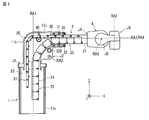
- FIG. 1 is an external perspective view of a robot arm mechanism of the robot apparatus according to the present embodiment.
- FIG. 2 is a side view showing the internal structure of the robot arm mechanism of FIG.
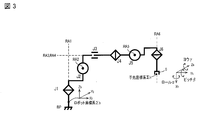
- FIG. 3 is a diagram showing the configuration of the robot arm mechanism of FIG.
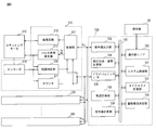
- FIG. 4 is a block diagram showing the configuration of the robot apparatus according to this embodiment.
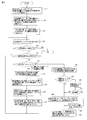
- FIG. 5 is a flowchart showing a processing procedure at the time of step-out by the operation control apparatus of FIG.
- FIG. 6 is a diagram showing a plurality of tracks after the step-out in FIG.
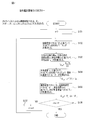
- FIG. 7 is a flowchart showing the procedure of step S13 in FIG.
- the robot apparatus according to this embodiment includes an operation control apparatus.
- the motion control device functions as a single device that controls the motor driver of each joint of the multi-joint arm mechanism provided in the robot device.
- the motion control device can also be incorporated in a robot device having an articulated arm mechanism.
- the motion control device of the robot apparatus according to the present embodiment can be applied to various types of articulated arm mechanisms.
- a multi-joint arm mechanism in which one of the plurality of joints is a linear motion expansion / contraction joint will be described as an example.
- components having substantially the same function and configuration are denoted by the same reference numerals, and redundant description will be given only when necessary.
- FIG. 1 is an external perspective view of a bot arm mechanism according to the present embodiment.
- the robot arm mechanism includes a substantially cylindrical base 10, an arm 2 connected to the base 10, and a wrist 4 attached to the tip of the arm 2.
- the wrist part 4 is provided with an adapter (not shown).
- the adapter is provided in a rotating portion of a sixth rotating shaft RA6 described later.
- a robot hand corresponding to the application is attached to the adapter provided on the wrist portion 4.
- the robot arm mechanism has a plurality of, here, six joint portions J1, J2, J3, J4, J5, and J6.
- the plurality of joint portions J1, J2, J3, J4, J5, and J6 are sequentially arranged from the base portion 10.
- the first, second, and third joints J1, J2, and J3 are called the root three axes
- the fourth, fifth, and sixth joints J4, J5, and J6 change the posture of the robot hand.
- the wrist 4 has fourth, fifth, and sixth joints J4, J5, and J6.
- At least one of the joint portions J1, J2, and J3 constituting the base three axes is a linear motion expansion / contraction joint.
- the third joint portion J3 is configured as a linear motion expansion / contraction joint portion, particularly a joint portion having a relatively long expansion / contraction distance.
- the arm part 2 represents the expansion / contraction part of the linear motion expansion / contraction joint part J3 (third joint part J3).
- the first joint portion J1 is a torsion joint centered on the first rotation axis RA1 supported, for example, perpendicularly to the base surface.
- the second joint portion J2 is a bending joint centered on the second rotation axis RA2 arranged perpendicular to the first rotation axis RA1.
- the third joint portion J3 is a joint in which the arm portion 2 expands and contracts linearly around a third axis (moving axis) RA3 arranged perpendicular to the second rotation axis RA2.
- the fourth joint portion J4 is a torsion joint centered on the fourth rotation axis RA4.
- the fourth rotation axis RA4 substantially coincides with the third movement axis RA3 when a later-described seventh joint portion J7 is not rotating, that is, when the entire arm portion 2 is linear.
- the fifth joint J5 is a bending joint centered on a fifth rotation axis RA5 orthogonal to the fourth rotation axis RA4.
- the sixth joint portion J6 is a bending joint centered on the sixth rotation axis RA6 that is perpendicular to the fourth rotation axis RA4 and perpendicular to the fifth rotation axis RA5.
- the arm support (first support) 11a forming the base 10 has a cylindrical hollow structure formed around the first rotation axis RA1 of the first joint J1.
- the first joint portion J1 is attached to a fixed base (not shown).
- the arm portion 2 pivots left and right along with the shaft rotation of the first support 11a.
- the first support 11a may be fixed to the ground plane.
- the arm part 2 is provided in a structure that turns independently of the first support 11a.
- a second support part 11b is connected to the upper part of the first support 11a.
- the second support portion 11b has a hollow structure that is continuous with the first support portion 11a.
- One end of the second support portion 11b is attached to the rotating portion of the first joint portion J1.
- the other end of the second support portion 11b is opened, and the third support portion 11c is fitted so as to be rotatable on the second rotation axis RA2 of the second joint portion J2.
- the 3rd support part 11c has a hollow structure which consists of a scale-like exterior which is connected to the 1st support part 11a and the 2nd support part.
- the third support portion 11c is accommodated in the second support portion 11b and sent out as the second joint portion J2 is bent and rotated.
- the rear part of the arm part 2 that constitutes the linear motion expansion / contraction joint part J3 (third joint part J3) of the robot arm mechanism is housed in the hollow structure in which the first support part 11a and the second support part 11b are continuous by contraction.
- the third support portion 11c is fitted to the lower end portion of the second support portion 11b so as to be rotatable about the second rotation axis RA2 at the lower end portion of the second support portion 11b.
- a second joint portion J2 as a bending joint portion around the second rotation axis RA2 is configured.
- the arm portion 2 rotates in a vertical direction around the second rotation axis RA2, that is, performs a undulation operation.
- the fourth joint portion J4 is a torsional joint having a fourth rotation axis RA4 that is typically in contact with the arm central axis along the expansion / contraction direction of the arm portion 2, that is, the third movement axis RA3 of the third joint portion J3.
- the fifth joint J5 is a bending joint having a fifth rotation axis RA5 orthogonal to the fourth rotation axis RA4 of the fourth joint J4.
- the sixth joint J6 is a bending joint having a sixth rotation axis RA6 perpendicular to the fourth rotation axis RA4 of the fourth joint J4 and perpendicular to the fifth rotation axis RA5 of the fifth joint J5.
- the robot hand turns left and right.
- the robot hand attached to the adapter of the wrist part 4 has the first, second and third joint parts J1. J2. It is moved to an arbitrary position by J3, and is arranged in an arbitrary posture by the fourth, fifth, and sixth joint portions J4, J5, and J6.
- the length of the extension / contraction distance of the arm portion 2 of the third joint portion J3 enables the robot hand to reach a wide range of objects from the proximity position of the base portion 10 to the remote position.
- the third joint portion J3 is characterized by a linear expansion / contraction operation realized by a linear motion expansion / contraction mechanism constituting the third joint portion J3 and a length of the expansion / contraction distance.
- FIG. FIG. 2 is a perspective view showing the internal structure of the robot arm mechanism of FIG.
- the linear motion expansion / contraction mechanism has an arm part 2 and an injection part 30.
- the arm unit 2 includes a first connection frame row 21 and a second connection frame row 22.
- the first connected frame row 21 includes a plurality of first connected frames 23.
- the first connection piece 23 is formed in a substantially flat plate shape.
- the front and rear first connecting pieces 23 are connected in a row so as to be freely bent by pins at the end portions of each other.
- column 21 can be bent freely inside and outside.
- the second linked frame row 22 includes a plurality of second linked frames 24.
- the second connecting piece 24 is configured as a short groove having a U-shaped cross section.
- the front and rear second connecting pieces 24 are connected in a row so as to be freely bent by pins at the bottom end portions of each other.
- the second connecting frame row 22 can be bent inward. Since the cross section of the second connecting piece 24 is U-shaped, the second connecting piece row 22 does not bend outward because the side plates of the adjacent second connecting pieces 24 collide with each other.
- the surfaces of the first and second connecting pieces 23 and 24 facing the second rotation axis RA2 are referred to as inner surfaces, and the opposite surfaces are referred to as outer surfaces.
- the first first linked frame 23 in the first linked frame sequence 21 and the first second linked frame 24 in the second linked frame sequence 22 are connected by a linked frame 27.
- the connecting piece 27 has a shape in which the second connecting piece 24 and the first connecting piece 23 are combined.
- the injection unit 30 includes a plurality of upper rollers 31 and a plurality of lower rollers 32 supported by a rectangular tube-shaped frame 35.
- the plurality of upper rollers 31 are arranged along the arm central axis at an interval substantially equal to the length of the first connecting piece 23.
- the plurality of lower rollers 32 are arranged along the arm central axis at an interval substantially equivalent to the length of the second connecting piece 24.
- a guide roller 40 and a drive gear 50 are provided behind the injection unit 30 so as to face each other with the first connecting piece row 21 interposed therebetween.
- the drive gear 50 is connected to the stepping motor 330 via a speed reducer (not shown).
- a linear gear is formed on the inner surface of the first connecting piece 23 along the connecting direction.
- the linear gears are connected in a straight line to form a long linear gear.
- the drive gear 50 is meshed with a linear linear gear.
- the linear gear connected in a straight line forms a rack and pinion mechanism together with the drive gear 50.
- the injection unit 30 joins the first and second connecting frame rows 21 and 22 to form a columnar body, and supports the columnar body vertically and horizontally.
- the columnar body formed by joining the first and second connecting piece rows 21 and 22 is firmly held by the injection unit 30, so that the joining state of the first and second connecting piece rows 21 and 22 is maintained.
- the bending of the first and second connection frame rows 21 and 22 is constrained to each other.
- columns 21 and 22 comprise the columnar body provided with fixed rigidity.
- the columnar body refers to a columnar rod body in which the first connection frame row 21 is joined to the second connection frame row 22.
- the second connecting piece 24 and the first connecting piece 23 are formed into cylindrical bodies having various cross-sectional shapes as a whole.
- the cylindrical body is defined as a shape in which the top, bottom, left and right are surrounded by a top plate, a bottom plate, and both side plates, and the front end and the rear end are open.
- the columnar body formed by joining the first and second connecting piece rows 21 and 22 starts from the connecting piece 27 and linearly extends from the opening of the third support portion 11c along the third movement axis RA3. Sent out.
- the first connecting piece row 21 engaged with the drive gear 50 is pulled back into the first support 11a.
- the columnar body is pulled back into the third support body 11c with the movement of the first connection frame row.
- the columnar body pulled back is separated behind the injection unit 30.
- the first connecting piece row 21 constituting the columnar body is sandwiched between the guide roller 40 and the drive gear 50, and the second connecting piece row 22 constituting the columnar body is pulled downward by gravity, whereby the second connecting piece row 22 is drawn.
- the frame row 22 and the first linked frame row 21 are separated from each other.
- the separated first and second connecting frame rows 21 and 22 are returned to a bendable state, bent inward in the same direction, and stored substantially in parallel inside the first support 11a.
- FIG. 3 is a diagram showing the robot arm mechanism of FIG.
- three position degrees of freedom are realized by the first joint portion J1, the second joint portion J2, and the third joint portion J3 that form the three base axes.
- three posture degrees of freedom are realized by the fourth joint portion J4, the fifth joint portion J5, and the sixth joint portion J6 constituting the wrist three axes.
- the robot coordinate system ⁇ b is a coordinate system having an arbitrary position on the first rotation axis RA1 of the first joint portion J1 as an origin.
- three orthogonal axes (Xb, Yb, Zb) are defined.
- the Zb axis is an axis parallel to the first rotation axis RA1.
- the Xb axis and the Yb axis are orthogonal to each other and orthogonal to the Zb axis.
- the hand coordinate system ⁇ h is a coordinate system having an arbitrary position (hand reference point) of the robot hand 5 attached to the wrist 4 as an origin.
- the position of the hand reference point (hereinafter simply referred to as the hand) is defined as the center position between the two fingers.
- the hand coordinate system ⁇ h three orthogonal axes (Xh, Yh, Zh) are defined.
- the Zh axis is an axis parallel to the sixth rotation axis RA6.
- the Xh axis and the Yh axis are orthogonal to each other and orthogonal to the Zh axis.
- the Xh axis is an axis parallel to the front-rear direction of the robot hand 5.
- the hand posture is a rotation angle around each of three orthogonal axes of the hand coordinate system ⁇ h with respect to the robot coordinate system ⁇ b (rotation angle around the Xh axis (yaw angle) ⁇ , rotation angle around the Yh axis (pitch angle) ⁇ , Zh axis It is given as the surrounding rotation angle (roll angle) ⁇ .
- 1st joint part J1 is arrange
- the rotation axis RA1 is arranged perpendicular to the reference plane BP of the base on which the fixing portion of the first joint portion J1 is installed.
- 2nd joint part J2 is comprised as a bending joint centering on rotating shaft RA2.
- the rotation axis RA2 of the second joint portion J2 is provided in parallel to the Xb axis on the spatial coordinate system.
- the rotation axis RA2 of the second joint portion J2 is provided in a direction perpendicular to the rotation axis RA1 of the first joint portion J1.
- the second joint portion J2 is offset with respect to the first joint portion J1 in two directions, that is, the direction of the first rotation axis RA1 (Zb axis direction) and the Yb axis direction perpendicular to the first rotation axis RA1.
- the second support 11b is attached to the first support 11a so that the second joint J2 is offset in the two directions with respect to the first joint J1.
- a virtual arm rod portion (link portion) that connects the second joint portion J2 to the first joint portion J1 has a crank shape in which two hook-shaped bodies whose tips are bent at right angles are combined.
- This virtual arm rod part is comprised by the 1st, 2nd support bodies 11a and 11b which have a hollow structure.
- 3rd joint part J3 is comprised as a linear motion expansion-contraction joint centering on movement axis RA3.
- the movement axis RA3 of the third joint portion J3 is provided in a direction perpendicular to the rotation axis RA2 of the second joint portion J2.
- the movement axis RA3 of the third joint portion J3 is the second joint
- the rotation axis RA2 of the part J2 and the rotation axis RA1 of the first joint part J1 are provided in a direction perpendicular to the rotation axis RA2.
- the movement axis RA3 of the third joint portion J3 is provided in parallel to the Yb axis perpendicular to the Xb axis and the Zb axis. Further, the third joint portion J3 is offset with respect to the second joint portion J2 in two directions, that is, the direction of the rotation axis RA2 (Yb axis direction) and the direction of the Zb axis orthogonal to the movement axis RA3.
- the third support 11c is attached to the second support 11b so that the third joint J3 is offset in the two directions with respect to the second joint J2.
- the virtual arm rod portion (link portion) that connects the third joint portion J3 to the second joint portion J2 has a hook-shaped body whose tip is bent vertically. This virtual arm rod portion is constituted by the second and third supports 11b and 11c.
- the fourth joint portion J4 is configured as a torsion joint with the rotation axis RA4 as the center.
- the rotation axis RA4 of the fourth joint part J4 is arranged to substantially coincide with the movement axis RA3 of the third joint part J3.
- the fifth joint J5 is configured as a bending joint with the rotation axis RA5 as the center.
- the rotation axis RA5 of the fifth joint portion J5 is disposed so as to be substantially orthogonal to the movement axis RA3 of the third joint portion J3 and the rotation axis RA4 of the fourth joint portion J4.
- the sixth joint portion J6 is configured as a torsion joint with the rotation axis RA6 as the center.
- the rotation axis RA6 of the sixth joint portion J6 is disposed so as to be substantially orthogonal to the rotation axis RA4 of the fourth joint portion J4 and the rotation axis RA5 of the fifth joint portion J5.
- the sixth joint J6 is provided to turn the robot hand 5 as a hand effector left and right.
- the sixth joint portion J6 may be configured as a bending joint whose rotation axis RA6 is substantially orthogonal to the rotation axis RA4 of the fourth joint portion J4 and the rotation axis RA5 of the fifth joint portion J5.
- one bending joint portion of the base three axes of the plurality of joint portions J1-J6 is replaced with a linear motion expansion / contraction joint portion, and the second joint portion J2 is offset in two directions with respect to the first joint portion J1.
- the robot arm mechanism of the robot apparatus according to the present embodiment eliminates the singularity posture structurally.
- FIG. FIG. 4 is a block diagram showing the configuration of the robot apparatus according to this embodiment.
- Stepping motors 310, 320, 330, 340, 350, and 360 are provided as actuators at joints J1, J2, J3, J4, J5, and J6 of the robot arm mechanism of the robot apparatus according to the present embodiment, respectively.
- Driver units 210, 220, 230, 240, 250, and 260 are electrically connected to the stepping motors 310, 320, 330, 340, 350, and 360.
- the driver units 210, 220, 230, 240, 250, and 260 are provided alongside the stepping motors 310, 320, 330, 340, 350, and 360 to be controlled.
- driver units 210, 220, 230, 240, 250, 260 have the same configuration, and perform the same operation on the stepping motor to be controlled according to the control signal from the operation control device 100.
- driver unit 210 will be described, and description of the other driver units 220, 230, 240, 250, and 260 will be omitted.
- the driver unit 210 controls the driving and stopping of the stepping motor 310.
- the driver unit 210 includes a control unit 211, a power supply circuit 212, a pulse signal generation unit 213, a rotary encoder 215, a step-out determination unit 216, and a counter 217.
- the control unit 211 controls the driver unit 210 in an integrated manner according to a control signal input from the operation control apparatus 100.
- control unit 211 in the driver unit 210 relates to a target position after the unit time ⁇ t of the rotation angle of the stepping motor 310 from the operation control device 100 (distinguished from a final target position described later).
- a position command signal is input.
- the control signal is given as a joint variable after ⁇ t (joint angle, expansion / contraction distance in J3).
- the control unit 211 determines the number of pulses Np based on the current position of the rotation angle of the stepping motor 310 and the target position.
- the control unit 211 calculates a rotation angle difference based on the current position of the rotation angle of the stepping motor 310 and the target position, and calculates the rotation angle difference between the current position and the target position of the stepping motor 310, for example, 0.
- the pulse number Np of the pulse signal is determined by dividing by a step angle of 72 degrees.
- the control unit 211 determines the pulse frequency fp based on the determined number of pulses and the unit time ⁇ t. Specifically, the control unit 211 determines the pulse frequency fp by multiplying the unit time ⁇ t by the pulse number Np and calculating the reciprocal thereof.
- the control unit 211 outputs a pulse number command signal related to the number of pulses and a pulse frequency command signal related to the pulse frequency to the pulse signal generation unit 213.
- the pulse signal generator 213 outputs a pulse signal having the number of pulses commanded by the pulse number command signal to each phase of the stepping motor 310 at a frequency commanded by the pulse frequency command signal, that is, a cycle of the reciprocal of the frequency.
- the pulse signal output from the pulse signal generation unit 213 is also taken into a step-out determination unit 216 described later.
- the controller 211 receives a drive current command signal that represents the drive current value of the stepping motor 310 from the operation control device 100.
- the control unit 211 outputs a control signal corresponding to the drive current command signal to the power supply circuit 212.
- the power supply circuit 212 generates a drive current having a designated drive current value using electric power supplied from an external power supply unit (not shown). The generated drive current is supplied to the stepping motor 310.
- the stepping motor 310 is driven by the drive current supplied from the power supply circuit 212 and is rotated according to the pulse signal output from the pulse signal generator 213.
- the rotary encoder 215 is connected to the drive shaft of the stepping motor 310 and outputs a pulse signal (encoder pulse) at a constant rotation angle of, for example, 0.18 degrees.
- the counter 217 calculates the count number by adding or subtracting the number of encoder pulses output from the rotary encoder 215 according to the rotation direction. This count number is reset at the reference position (origin) of the drive shaft of the stepping motor 310.
- the joint angle (joint variable) of the joint is obtained from the number of resets and the count.
- the step-out determination unit 216 determines whether the stepping motor 310 has stepped out or has stepped out by comparing the number of encoder pulses counted with respect to the pulse signal output from the pulse signal generation unit 213. .
- the step-out determination unit 216 repeats counting / resetting the encoder pulse in synchronization with the pulse signal.
- the step angle that rotates in one cycle of the pulse signal is fixed.
- the number of encoder pulses corresponding to the step angle is fixed. If the count number of the encoder pulse matches the number corresponding to the step angle, the rotation of the stepping motor 310 is synchronized with the pulse signal, that is, no step-out has occurred.
- the step out determination unit 216 generates a step out detection signal.
- the motion control apparatus 100 includes a system control unit 101, an operation unit interface 102, a command value output unit 103, a current position / attitude calculation unit 104, a trajectory calculation unit 105, a command value calculation unit 106, and a dynamics calculation unit. 107, a drive current determination unit 108, and a driver unit interface 109. From the driver unit 210, the operation control device 100 outputs the count number (representing the rotation angle from the reference position) counted by the counter 217 and the number of resets (representing the number of rotations) and the step-out determination unit 216. The step-out detection signal is input via the driver unit interface 109.
- the robot apparatus motion control apparatus 100 according to the present embodiment can be applied as an independent apparatus to other apparatuses and mechanisms that use a stepping motor.
- the system control unit 101 includes a CPU (Central Processing Unit), a semiconductor memory, and the like, and controls the operation control apparatus 100 in an integrated manner. Each unit is connected to the system control unit 101 via a control / data bus 110.
- CPU Central Processing Unit
- semiconductor memory and the like
- An operation unit 50 is connected to the operation control apparatus 100 via an operation unit interface 102.
- the operation unit 50 functions as an input interface for the user to input a change in the position of the point of interest of the wrist 4 or the robot hand (hand effector), a change in posture, and a change time.
- the motion control apparatus 100 executes calculation processing such as movement / posture change using, for example, the tip of a two-finger hand as a point of interest (control point).
- the operation unit 50 includes a joystick or the like for designating a final target position for moving the robot hand and a moving time.
- the final target position and movement time of the robot hand are input based on the direction in which the joystick is operated, the angle at which the joystick is tilted, and the operation acceleration of the joystick.
- these input devices constituting the operation unit 50 can be replaced with other devices such as a mouse, a keyboard, a trackball, and a touch panel.
- the command value output unit 103 outputs the command value (joint angle after ⁇ t (joint variable)) for each joint portion J1-J6 calculated by the command value calculation unit 106, which will be described later, under the control of the system control unit 101. Output to 210, 220, 230, 240, 250, 260. Specifically, the command value output unit 103 sends position command signals corresponding to the joint variables for the joints J1-J6 calculated by the command value calculation unit 106, which will be described later, to the driver units 210, 220, 230, 240, 250. , 260 are output.
- command value output unit 103 outputs a drive current command signal corresponding to the drive current value for driving each of the joints J1-J6 determined by the drive current determination unit 108, which will be described later, to the driver units 210, 220, 230, 240, It outputs to 250,260.
- the current position / posture calculation unit 104 performs forward kinematics based on the joint transformation matrix defined according to the link parameters of the arm structure based on the joint variables of the joints J1, J2, J3, J4, J5, and J6.
- the position and orientation of the point of interest of the hand as seen from the robot coordinate system are calculated.
- the joint variable is a positive or negative rotation angle from the reference position in the joint portions J1, J2, J4, J5, and J6, and in the joint portion J3, the extension distance (linear displacement) from the most contracted state. .
- Joint variable vector for the joints J1-J6 - calculate the ⁇ .
- Joint variable vector - theta is given by a rotating joint J1, J2, J4, J5, J6 of joint angle ⁇ J1, ⁇ J2, ⁇ J4 , ⁇ J5, ⁇ J6 and telescopic length L J3 of linear expansion joints J3 Is a set of joint variables ( ⁇ J1 , ⁇ J2 , L J3 , ⁇ J4 , ⁇ J5 , ⁇ J6 ).
- the current position / posture calculation unit 104 holds the cumulative count number before starting the stepping motor 310 of the joint portion J1, and adds the count number counted during the startup to the cumulative count number. Update the number.
- the current position / posture calculation unit 104 calculates the rotation angle from the reference position of the stepping motor 310 by multiplying the accumulated count by a step angle corresponding to 1 count, and specifies the joint variable of the joint portion J1.
- the current position / posture calculation unit 104 identifies the joint variables of the other joints J2-J6 by the same method.
- the current position / attitude calculation unit 104 uses the homogeneous transformation matrix K (parameters ( ⁇ J1 , ⁇ J2 , L J3 , ⁇ J4 , ⁇ J5 , ⁇ J6 )) to determine the position of the point of interest of the hand as viewed from the robot coordinate system ⁇ b. Calculate (x, y, z) and hand posture ( ⁇ , ⁇ , ⁇ ).
- the homogeneous transformation matrix K is a determinant that defines the relationship between the hand coordinate system ⁇ h and the robot coordinate system ⁇ b.
- the homogeneous transformation matrix K is determined by the relationship between the links constituting the robot arm mechanism (link length and link twist angle) and the relationship between the joint axes (distance between links and angle between links).
- current position and orientation calculation unit 104 the joint variable vector of the current robot arm mechanism - ⁇ 0 ( ⁇ 0-J1 , ⁇ 0-J2, L 0-J3, ⁇ 0-J4, ⁇ 0-J5, ⁇
- the current position P0 x 0 , y 0 , z 0
- the hand posture ⁇ 0 ⁇ 0 , ⁇ 0 , ⁇ 0 .
- the trajectory calculation unit 105 calculates a point sequence of the target position of the hand for each unit time ⁇ t (control cycle, for example, 10 ms) connecting between the current position / posture of the hand and the final target position / posture of the hand. To do.
- the current position / posture of the hand is obtained from calculation processing by the current position / posture calculation unit 104.
- the final target position / posture of the hand and the movement time are input by the user via the operation unit 50, for example.
- the trajectory calculation unit 105 substitutes each parameter into a preset function that has the current position and current posture of the hand and the final target position and final target posture of the hand as parameters.
- a target position per unit time ⁇ t is calculated on the hand trajectory.
- An arbitrary method is adopted as the trajectory calculation method.
- the unit time ⁇ t is a fixed value as the control cycle, and is set to 10 ms by the user, for example.
- the target position is a parameter that gives both the position and posture of the hand.
- the trajectory calculation unit 105 can recalculate five types of trajectories under the control of the system control unit 101 when a step-out is detected.
- the first to third trajectories are trajectories from the position of the point of interest of the hand shifted from the original trajectory due to the step-out (movement restart position) to the final target position through different paths.
- the fourth and fifth trajectories are trajectories that return from the movement resumption position to a position at the start of movement through different paths.
- one of the five tracks is selected, and movement control is performed along the track.
- the trajectory calculation method is arbitrary, and a plurality of functions may be preset.
- the trajectory calculation unit 105 changes the function used for the calculation of the hand trajectory according to the control of the system control unit 101.
- the trajectory calculation unit 105 recalculates the hand trajectory after the step-out detection using a function different from the function used for the normal hand trajectory calculation.
- the hand trajectory calculated again after the step-out detection is equivalent to the shortest path connecting the position P0 ′ after the step-out detection and the final target position P1.
- the hand trajectory calculated again after the step-out detection has a trajectory in which the hand is pulled back by a predetermined distance from the position after the escape detection to the position at the time of the step-out detection.
- the command value calculation unit 106 calculates a plurality of joint variable vectors respectively corresponding to the target positions arranged on the calculated trajectory with a period of ⁇ t.
- the joint variable vector refers to six variables of the joint portions J1-J6, that is, six variables of the rotation angles of the rotary joint portions J1, J2, J4-J6 and the arm expansion / contraction length of the linear motion expansion / contraction joint portion J3. The calculation process of the command value calculation unit 106 will be described later.
- the dynamics calculation unit 107 includes torques (drive torques) of the respective stepping motors 310 to 360 provided at the joints J1 to J6 that are required to move the hand from the target position to the next target position after ⁇ t. Calculate Further, the dynamics calculation unit 107 calculates a torque (static torque) required for each joint unit to make the arm unit 2 stationary.
- the static torque required for each joint is equivalent to the load torque related to the joint calculated in the opposite direction to the mass of the center of gravity of the portion ahead of the joint, the distance from the rotation axis of the joint to the center of gravity, etc. Torque, that is, torque that balances the load torque due to its own weight.
- the required torque of each of the stepping motors 310 to 360 uses the dynamics model data related to the joint portion J1-J6, and the center of gravity position, the center-of-gravity mass, the link length, the inertia tensor of each link connecting the joint portion J1-J6 of the robot arm mechanism, It is calculated from joint variables (rotational angle position or linear motion displacement), joint angular velocity, joint angular acceleration, etc. of the joint.
- the dynamics model refers to a model related to motor dynamic characteristics.
- the drive current determination unit 108 determines the drive current values of the stepping motors 310, 320, 330, 340, 350, and 360 in order to generate the torque calculated by the dynamics calculation unit 107.
- the drive current determination unit 108 holds data of a correspondence table in which the magnitude of torque and the drive current value of each of the stepping motors 310, 320, 330, 340, 350, and 360 are associated with each other.
- the drive current determination unit 108 refers to the correspondence table and determines a drive current value corresponding to the magnitude of each of the joints J1 to J6 calculated by the dynamics calculation unit 107.
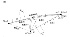
- FIGS. 5 and 6 are diagrams showing the first to fifth trajectories (1) to (5). Each unit of the operation control apparatus 100 is operated according to the flowchart of FIG.
- Step S11 Input of final target position, etc.
- the final target position of the point of interest of the hand is input via the operation unit interface 102.
- the final target position P1 is input.
- a waiting time tw from the step out to the movement resumption is set.
- the standby time tw can be set to 0 or more. The fact that the waiting time tw is set to 0 hours naturally means that the resumption of movement is permitted immediately.
- Step S12 Calculation process of hand trajectory
- the trajectory calculation unit 105 calculates the hand trajectory from the current position (movement start position) of the hand point of interest to the final target position input in step S11.
- the trajectory calculation unit 105 sets a plurality of target positions per unit time ⁇ t on the hand trajectory from the current position of the hand focus point to the final target position.
- the current position P 0 of the hand point of interest is obtained from calculation processing by the current position / posture calculation unit 104.
- the current position and orientation calculation unit 104 based on the count number counted by the driver unit 210,220,230,240,250,260 each counter 217, the current joint variable vector - theta 0 ( ⁇ 0-J1 , ⁇ 0-J2 , L 0-J3 , ⁇ 0-J4 , ⁇ 0-J5 , ⁇ 0-J6 ) are calculated and based on the joint variable vector ⁇ ⁇ 0 Is calculated.
- Step S13 Calculation processing of command value (joint variable vector) of joint portion J1-J6
- the command value calculation unit 106 calculates a plurality of joint variable vectors representing the angles and extension distances of the joints respectively corresponding to the plurality of target positions calculated in step S12.
- Step S14 Command Value Output Processing
- the position command signal corresponding to the joint variable vector calculated in step S13 and the drive current command signal corresponding to the drive current value determined by the drive current determination unit 108 are the command values.
- the output unit 103 sequentially outputs the driver units 210, 220, 230, 240, 250, and 260 at a predetermined control cycle ⁇ t (for example, 10 ms).
- ⁇ t for example, 10 ms
- Step S15 Judgment processing of whether the hand has reached the final target position
- the system control unit 101 determines whether the hand has reached the final target position. Specifically, the current position / attitude calculation unit 104 compares the current position of the hand calculated for each control cycle ⁇ t with the final target position P1 shown in FIG. When the current position of the hand matches the final target position, it is determined that the hand has reached the final target position. At this time, a series of control by the operation control apparatus 100 is completed. On the other hand, when the current position of the hand does not match the final target position of the hand, the process proceeds to step S16.
- Step S16 Judgment processing for occurrence of step-out
- the system control unit 101 determines whether or not a step-out has occurred. Specifically, when a step-out detection signal is input from the step-out determination unit 216 to the operation control apparatus 100, the process proceeds to step S17.
- the position of the hand at the time of step-out detection is Pso, and some external cause, for example, the operator touches the arm part 2 of the robot arm mechanism, and the hand is moved to the position P0 ′. .
- the position command signal and the drive current command signal have a predetermined control cycle ⁇ t until the current position of the hand reaches the final target position of the hand. Are output sequentially.
- Step S17 Recalculation processing of hand trajectory at the time of occurrence of step-out
- the system control unit 101 maintains the initial final target position P1 as the arrival position when the hand movement is resumed after the step-out detection, or the position P0 at the start of movement from the initial final target position P1.
- the distance ⁇ d shifted by step-out that is, the distance (shift distance) ⁇ d between the hand position Pso at the time of step-out detection on the initial trajectory and the hand position P0 ′ shifted after the step-out occurs.
- the operation control unit 100 controls the driver unit 210 to repeatedly output a command value for resuming movement, and retry movement resumption. Let this repetition period (retry period) be ⁇ t1, and the number of repetitions (retry number) be n.
- the state in which the number of pulse signals from the pulse signal generation unit 213 matches the number of encoded pulses is a state in which step-out has been eliminated, and movement can be resumed in that state.
- the retry control for resuming movement is repeated until this state is achieved.
- step S17 the position of the hand does not significantly deviate from the original trajectory due to the step-out (the shift distance ⁇ d is relatively short), and a long time elapses until the step-out occurs and is resolved. If it is not (downtime n ⁇ ⁇ t1 is relatively short), the movement is resumed and the initial final target position is aimed at, while the hand position greatly deviates from the original trajectory due to the step-out, ( When the shift distance [Delta] d is relatively long) and / or when a long time has passed after the occurrence of the step-out and it is resolved (downtime n. [Delta] t1 is relatively long), the initial final target position is set. It is released, returns to the movement start position, and waits for the next task.
- the threshold value THd compared with the shift distance ⁇ d to determine the length of the shift distance ⁇ d and the downtime (n ⁇ ⁇ t1) to determine the length of the downtime (n ⁇ ⁇ t1).
- the threshold value THt is dynamically changed by the system control unit 101. For example, a relatively small value is set when the position Pso at the time of step-out detection is closer to the movement start position P0 than the final target position P1, and a comparison is made when the position Pso at the time of step-out detection is closer to the final target position P1 than the movement start position P0. Is set to a large value.
- step S18 the system control unit 101 waits for the movement to be resumed until a movement resumption instruction is input by the operator. To do. Or when the manual instruction
- step S19 When a movement resumption instruction is input by the operator in step S18 or when the standby time tw has elapsed, a command value is output according to the trajectory selected in steps S19 to S21, and movement is resumed.
- the trajectory recalculation step S19 and the trajectory selection step S20 are executed in parallel with the step S18.
- step S19 the three types of trajectories (1) to (3) shown in FIG.
- the first trajectory (1) is out of step from the initial trajectory from the movement start position P0 to the final target position P1 from the position of the point of interest of the hand shifted due to the out-of-step (position when resuming movement) P0 '.
- This is a trajectory that follows a path deviated due to the above, returns to the out-of-step detection position Pso on the original trajectory, and reaches the final target position along the initial trajectory.
- the second trajectory (2) is a position between the position Pso 'at the time of step-out detection and the final target position P1 from the position of the point of interest of the hand shifted due to the step-out (position at the time of resuming movement) P0'. Is a trajectory that reaches the final target position along the initial trajectory.
- the third trajectory (3) is the shortest linear trajectory from the position P0 'of the target point shifted due to the step-out to the final target position P1.
- step S20 one of the three types of trajectories (1) to (3) is selected by the trajectory calculation unit 105 or the system control unit 101.
- the first orbit (1) has the first priority
- the second orbit (2) has the second priority
- the third orbit (3) has the third priority.
- the task time that is originally set for the movement from the initial movement start position P0 to the final target position P1 is less than the predetermined upper speed limit for the movement speed of the point of interest. Can be maintained within or not. If the first track (1) that has the longest track length and is assumed to have the highest safety satisfies the selection condition, the first track (1) is selected.
- the second trajectory (2) is selected.
- the third trajectory (3) Is selected. Note that the operation when the third trajectory (3) does not satisfy the selection condition is arbitrarily set, and may typically remain at the movement resumption position P0 ′, or the fourth trajectory (4 ) May be selected to return to the movement start position P0 and wait for the next task.
- command values representing a plurality of joint variable vectors respectively corresponding to a plurality of target positions on the trajectory selected in step S20 are calculated by the command value calculation unit 106, and sequentially in a cycle of a predetermined control cycle ⁇ t.
- step S17 If “NO” in the step S17, that is, if it is determined that the movement is resumed and the return trajectory (4) or (5) is followed to return to the original movement start position P0, the system control is performed in the step S22.
- the unit 101 waits for resumption of movement until an instruction for resuming movement by the operator is input, or waits for the elapse of the standby time tw set in step S11 from the time of step-out detection.
- step S23 When a movement resumption instruction is input by the operator in step S22 or when the standby time tw has elapsed, in step S23, the “return trajectory (4), (5) returning to the movement start position P0 set in step S11”.
- Manual selection function is set to OFF, in step S24, the trajectory calculation unit 105 determines from the position of the point of interest of the hand shifted due to the step-out (position when resuming movement) P0 ′. A return trajectory (4) returning to the original movement start position P0 is calculated.
- the return trajectory (4) returns to the out-of-step detection position Pso from the position P0 'at the time of resuming the movement, following a path deviated from the initial trajectory from the movement start position P0 to the final target position P1 due to the out-of-step. This is a trajectory going back to the original movement start position P0 from the original trajectory.
- the fifth trajectory (5) is a linear shortest return trajectory from the position of the point of interest (movement restart position) P0 'shifted due to the step-out to the original movement start position P0.
- the return trajectory (4) is the path that has just passed, it can be said that the possibility of an obstacle or the like intervening on the trajectory is lower than that of the new fifth trajectory (5), that is, the safety is high. Therefore, when the operator does not manually select the trajectory, the return trajectory (4) is preferentially selected as the return trajectory (5).
- step 25 a command value representing a plurality of joint variable vectors respectively corresponding to a plurality of target positions on the trajectory (4) calculated in step S24 is calculated by the command value calculation unit 106, and a predetermined control cycle ⁇ t.
- the command value is output from the command value output unit 103 to the driver units 210, 220, 230, 240, 250, and 260 together with the command signal representing the drive current value at each position determined by the drive current determination unit 108 in order in a cycle. .
- step S23 when the “manual selection function of the return trajectory (4), (5) returning to the movement start position P0)” set in step S11 is set to ON, in step S26, the operation is performed by the system control unit 101.
- a screen for prompting the operator to select either the return trajectory (4) or the fifth trajectory (5) is displayed on the display of the unit 50.
- the process proceeds to step S24.
- the trajectory calculation unit 105 in step S28 performs the original movement from the position of the point of interest of the hand shifted due to the step-out (position when the movement is resumed) P0 '.
- the return trajectory (5) which returns linearly to the start position P0 in the shortest time is calculated, and the process proceeds to step S25.
- steps S14 to S28 are repeated until the point of interest of the hand 5 reaches the final target position P1 or returns to the movement start position P0 through step S15.
- step-out which is a characteristic unique to a stepping motor
- a safety mechanism has been required such as detecting the contact with an acceleration sensor or the like to stop the operation.
- a step-out occurs due to the load, and the operation stops. Therefore, the same safety as in the prior art can be ensured.
- a variable n is used.
- this variable n is initialized to a zero value.
- Jacobian inverse matrix J -1 (- ⁇ n) calculation of The robot arm mechanism of the robot apparatus according to the present embodiment has no singular point due to its structure, and therefore a Jacobian inverse matrix always exists.
- the Jacobian inverse matrix is a matrix that converts the hand speed (minor change in hand position / posture) to the joint angular velocity (minor change in joint angle / extension / contraction length).
- the Jacobian inverse matrix is given by the knitting differential with the joint variable of the vector representing the hand position / hand posture.
- Step S133 Calculation of hand speed ⁇ pn + 1 Based on the current hand position (current target position) pn, the next hand position (next target position after unit time ⁇ t) pn + 1, and the unit time ⁇ t, the hand speed ⁇ pn + 1 is calculated.
- Step S134 Calculation of Joint Angular Velocity- ⁇ ⁇ n + 1
- the - (.theta.n), joint angular velocity - - calculated hand speed in step S133 pn + 1 is a Jacobian inverse matrix J -1 are converted into ⁇ ⁇ n + 1.
- the displacement amount of each joint during the unit time ⁇ t is calculated.
- Joint variable vector of the moving just before - by adding the displacement amount of the joint .theta.n, joint variable vector after unit time ⁇ t elapses - .theta.n + 1 is calculated.
- Step S136 Determination of processing continuation
- the variable n is the number of repetitions (m ⁇ 1)
- the calculation process by the command value calculation unit 106 is terminated.
- the variable (n) is not the number of repetitions (m ⁇ 1)
- the process proceeds to step S137.
- Step S137 Raise variable n ⁇ n + 1
- the variable n is incremented to (n + 1), and the process returns to step S142.
- the joint portions J1-J6 constituting the robot arm mechanism are provided with the stepping motors 310 to 360, respectively.
- the operations of these stepping motors 310 to 360 are controlled by the operation control device 100.
- a stepping motor is not generally used for industrial robots because a step-out occurs when a load larger than the torque of the stepping motor is applied to the stepping motor.
- the robot apparatus according to the present embodiment does not have a singular point in structure, and therefore the arm does not perform a large turning movement to avoid the singular point at an unexpected timing.
- it can be used as a co-robot device that performs work. That is, the robot apparatus according to the present embodiment can be arranged close to the worker.
- the stepping motor will step out if a load exceeding the required torque of the stepping motor is applied to the stepping motor. Therefore, the arm does not harm the operator with a large force exceeding the required torque of the stepping motor. Therefore, by using a stepping motor for the actuator of the joint part, the risk of injury of the worker due to the arm coming into contact with the worker can be reduced compared to the case of using another motor, such as an AC motor. it can.
- the post-step-out position may deviate from the planned hand trajectory.
- the trajectory calculation unit 105 of the motion control apparatus 100 of the robot apparatus according to the present embodiment moves from the current position of the hand after the step-out detection to the final target position of the hand.
- the hand trajectory can be calculated again. Therefore, even when a step-out occurs, the hand movement control is continued, and the hand can be moved again from the position after the step-out detection to the final target position.
- the robot apparatus can provide a preferable countermeasure when a step-out occurs on the premise that a step-out occurs in the stepping motor.
- the stepping motor control has been described by taking the robot apparatus as an example.
- the stepping motor can be applied to another operation target, for example, a line movement actuator of the conveyor apparatus, and can be applied to the stepping motor control.
- a process in which the line as the operation target changes (speed change) from the current state (current speed) to the target state (target speed) is calculated, and a command value is output according to the process.
- the stepping motor has stepped out in the process, the process from the line speed at the time of the step-out to the target speed is calculated again, and the line speed is changed stepwise according to the recalculated process.
- Such application is also within the concept of this embodiment.
Landscapes
- Engineering & Computer Science (AREA)
- Robotics (AREA)
- Mechanical Engineering (AREA)
- Human Computer Interaction (AREA)
- Manipulator (AREA)
Abstract
Supposing that step-out occurs in a stepping motor, in order to provide a suitable response when the step-out has occurred, this robot device is provided with: a robot arm mechanism which has a joint; a stepping motor (310) which generates power for actuating the joint; a motor driver (210) which drives the stepping motor; a trajectory calculation unit (105) which calculates the trajectory along which a point of interest on the robot arm mechanism moves from the current position to a final target position; a command value output unit (103) which outputs to the motor driver a command value that depends on the trajectory calculated by the trajectory calculation unit; and a step-out detection unit (216) which detects step-out of the stepping motor. Further, this robot device is provided with a system control unit (101). When a step-out is detected, the system control unit controls the trajectory calculation unit and the command value calculation unit such that the trajectory of the position of the point of interest to the final target position, which shifts due to the step-out, is re-calculated and the point of interest is moved along the re-calculated trajectory.
Description
本発明の実施形態はロボット装置及びステッピングモータ制御装置に関する。
Embodiments described herein relate generally to a robot apparatus and a stepping motor control apparatus.
ステッピングモータは、回転角がパルス信号の数に比例するので基本的にフィードバック回路の必要性がなく、オープンループ制御が可能であるで、ACモータ、DCモータよりも有利である反面、過負荷がかかったり、パルス周波数が高すぎると同期外れで制御が乱れるいわゆる「脱調」が生じる。脱調が発生すると、ステッピングモータが停止する。また再開しても目標位置には到達させるには基準位置に戻すことが必要とされ、それによるダウンタイムは避けられない。脱調現象はステッピングモータに不可避であり、従ってステッピングモータが脱調を起こさないよう様々な工夫が従来からなされてきたが、その多くが対症的であった。
A stepping motor is basically free from the need for a feedback circuit because the rotation angle is proportional to the number of pulse signals, and is capable of open-loop control. It is more advantageous than an AC motor or DC motor, but has an overload. If the pulse frequency is too high, a so-called “step-out” occurs where control is disturbed due to loss of synchronization. When step-out occurs, the stepping motor stops. Further, even if restarting, it is necessary to return to the reference position in order to reach the target position, and downtime due to this is inevitable. The step-out phenomenon is unavoidable for stepping motors. Therefore, various attempts have been made to prevent stepping motors from stepping out, and many of them have been symptomatic.
目的は、ステッピングモータに脱調が生じることを前提として脱調が生じたときの好適な対処を提供することにある。
The purpose is to provide a suitable countermeasure when a step-out occurs on the assumption that a step-out motor will step out.
本実施形態に係るロボット装置は、関節部を有するロボットアーム機構と、関節部を作動させる動力を発生するステッピングモータと、ステッピングモータを駆動するモータドライバとを、ロボットアーム機構の着目点が現在位置から最終目標位置まで移動する軌道を計算する軌道計算部と、軌道計算部で計算された軌道に応じた指令値をモータドライバに出力する指令値出力部と、ステッピングモータの脱調を検知する脱調検知部とを備える。さらにロボット装置はシステム制御部を備える。システム制御部は、脱調が検知されたとき、脱調に起因してシフトした着目点の位置から最終目標位置までの軌道を再度計算させ、再度計算された軌道に従って着目点を移動させるために軌道計算部と指令値出力部とを制御する。
The robot apparatus according to the present embodiment includes a robot arm mechanism having a joint, a stepping motor that generates power for operating the joint, and a motor driver that drives the stepping motor. A trajectory calculation unit that calculates a trajectory that travels from the target position to the final target position, a command value output unit that outputs a command value corresponding to the trajectory calculated by the trajectory calculation unit, and a stepping motor that detects step-out of the stepping motor And a tone detection unit. Furthermore, the robot apparatus includes a system control unit. When the step-out is detected, the system control unit recalculates the trajectory from the position of the focus point shifted due to the step-out to the final target position, and moves the focus point according to the re-calculated trajectory. The trajectory calculation unit and the command value output unit are controlled.
以下、図面を参照しながら本実施形態に係るロボット装置を説明する。本実施形態に係るロボット装置は動作制御装置を備える。動作制御装置は、ロボット装置に装備されている多関節アーム機構の各関節のモータドライバを制御する単独の装置として機能する。また動作制御装置は、多関節アーム機構を備えるロボット装置に組み込むこともできる。本実施形態に係るロボット装置の動作制御装置は様々な形態の多関節アーム機構に適用可能である。ここでは複数の関節部のうち一が直動伸縮関節の多関節アーム機構を一例として説明する。以下の説明において、略同一の機能及び構成を有する構成要素については、同一符号を付し、重複説明は必要な場合にのみ行う。
Hereinafter, the robot apparatus according to the present embodiment will be described with reference to the drawings. The robot apparatus according to this embodiment includes an operation control apparatus. The motion control device functions as a single device that controls the motor driver of each joint of the multi-joint arm mechanism provided in the robot device. The motion control device can also be incorporated in a robot device having an articulated arm mechanism. The motion control device of the robot apparatus according to the present embodiment can be applied to various types of articulated arm mechanisms. Here, a multi-joint arm mechanism in which one of the plurality of joints is a linear motion expansion / contraction joint will be described as an example. In the following description, components having substantially the same function and configuration are denoted by the same reference numerals, and redundant description will be given only when necessary.
図1は、本実施形態に係るボットアーム機構の外観斜視図である。ロボットアーム機構は、略円筒形状の基部10と基部10に接続されるアーム部2とアーム部2の先端に取り付けられる手首部4とを有する。手首部4には図示しないアダプタが設けられている。例えば、アダプタは後述の第6回転軸RA6の回転部に設けられる。手首部4に設けられたアダプタには、用途に応じたロボットハンドが取り付けられる。
FIG. 1 is an external perspective view of a bot arm mechanism according to the present embodiment. The robot arm mechanism includes a substantially cylindrical base 10, an arm 2 connected to the base 10, and a wrist 4 attached to the tip of the arm 2. The wrist part 4 is provided with an adapter (not shown). For example, the adapter is provided in a rotating portion of a sixth rotating shaft RA6 described later. A robot hand corresponding to the application is attached to the adapter provided on the wrist portion 4.
ロボットアーム機構は、複数、ここでは6つの関節部J1,J2,J3,J4,J5,J6を有する。複数の関節部J1,J2,J3,J4,J5,J6は基部10から順番に配設される。一般的に、第1、第2、第3関節部J1,J2,J3は根元3軸と呼ばれ、第4、第5、第6関節部J4,J5,J6はロボットハンドの姿勢を変化させる手首3軸と呼ばれる。手首部4は第4、第5、第6関節部J4,J5,J6を有する。根元3軸を構成する関節部J1,J2,J3の少なくとも一つは直動伸縮関節である。ここでは第3関節部J3が直動伸縮関節部、特に伸縮距離の比較的長い関節部として構成される。アーム部2は直動伸縮関節部J3(第3関節部J3)の伸縮部分を表している。
The robot arm mechanism has a plurality of, here, six joint portions J1, J2, J3, J4, J5, and J6. The plurality of joint portions J1, J2, J3, J4, J5, and J6 are sequentially arranged from the base portion 10. In general, the first, second, and third joints J1, J2, and J3 are called the root three axes, and the fourth, fifth, and sixth joints J4, J5, and J6 change the posture of the robot hand. Called wrist 3 axis. The wrist 4 has fourth, fifth, and sixth joints J4, J5, and J6. At least one of the joint portions J1, J2, and J3 constituting the base three axes is a linear motion expansion / contraction joint. Here, the third joint portion J3 is configured as a linear motion expansion / contraction joint portion, particularly a joint portion having a relatively long expansion / contraction distance. The arm part 2 represents the expansion / contraction part of the linear motion expansion / contraction joint part J3 (third joint part J3).
第1関節部J1は基台面に対して例えば垂直に支持される第1回転軸RA1を中心としたねじり関節である。第2関節部J2は第1回転軸RA1に対して垂直に配置される第2回転軸RA2を中心とした曲げ関節である。第3関節部J3は、第2回転軸RA2に対して垂直に配置される第3軸(移動軸)RA3を中心として直線的にアーム部2が伸縮する関節である。
The first joint portion J1 is a torsion joint centered on the first rotation axis RA1 supported, for example, perpendicularly to the base surface. The second joint portion J2 is a bending joint centered on the second rotation axis RA2 arranged perpendicular to the first rotation axis RA1. The third joint portion J3 is a joint in which the arm portion 2 expands and contracts linearly around a third axis (moving axis) RA3 arranged perpendicular to the second rotation axis RA2.
第4関節部J4は、第4回転軸RA4を中心としたねじり関節である。第4回転軸RA4は、後述の第7関節部J7が回転していないとき、つまりアーム部2の全体が直線形状にあるとき、第3移動軸RA3と略一致する。第5関節部J5は第4回転軸RA4に対して直交する第5回転軸RA5を中心とした曲げ関節である。第6関節部J6は第4回転軸RA4に対して直交し、第5回転軸RA5に対して垂直に配置される第6回転軸RA6を中心とした曲げ関節である。
The fourth joint portion J4 is a torsion joint centered on the fourth rotation axis RA4. The fourth rotation axis RA4 substantially coincides with the third movement axis RA3 when a later-described seventh joint portion J7 is not rotating, that is, when the entire arm portion 2 is linear. The fifth joint J5 is a bending joint centered on a fifth rotation axis RA5 orthogonal to the fourth rotation axis RA4. The sixth joint portion J6 is a bending joint centered on the sixth rotation axis RA6 that is perpendicular to the fourth rotation axis RA4 and perpendicular to the fifth rotation axis RA5.
基部10を成すアーム支持体(第1支持体)11aは、第1関節部J1の第1回転軸RA1を中心に形成される円筒形状の中空構造を有する。第1関節部J1は図示しない固定台に取り付けられる。第1関節部J1が回転するとき、アーム部2は第1支持体11aの軸回転とともに左右に旋回する。なお、第1支持体11aが接地面に固定されていてもよい。その場合、第1支持体11aとは独立してアーム部2が旋回する構造に設けられる。第1支持体11aの上部には第2支持部11bが接続される。
The arm support (first support) 11a forming the base 10 has a cylindrical hollow structure formed around the first rotation axis RA1 of the first joint J1. The first joint portion J1 is attached to a fixed base (not shown). When the first joint portion J1 rotates, the arm portion 2 pivots left and right along with the shaft rotation of the first support 11a. The first support 11a may be fixed to the ground plane. In that case, the arm part 2 is provided in a structure that turns independently of the first support 11a. A second support part 11b is connected to the upper part of the first support 11a.
第2支持部11bは第1支持部11aに連続する中空構造を有する。第2支持部11bの一端は第1関節部J1の回転部に取り付けられる。第2支持部11bの他端は開放され、第3支持部11cが第2関節部J2の第2回転軸RA2において回動自在に嵌め込まれる。第3支持部11cは第1支持部11a及び第2支持部に連通する鱗状の外装からなる中空構造を有する。第3支持部11cは、第2関節部J2の曲げ回転に伴ってその後部が第2支持部11bに収容され、また送出される。ロボットアーム機構の直動伸縮関節部J3(第3関節部J3)を構成するアーム部2の後部はその収縮により第1支持部11aと第2支持部11bの連続する中空構造の内部に収納される。
The second support portion 11b has a hollow structure that is continuous with the first support portion 11a. One end of the second support portion 11b is attached to the rotating portion of the first joint portion J1. The other end of the second support portion 11b is opened, and the third support portion 11c is fitted so as to be rotatable on the second rotation axis RA2 of the second joint portion J2. The 3rd support part 11c has a hollow structure which consists of a scale-like exterior which is connected to the 1st support part 11a and the 2nd support part. The third support portion 11c is accommodated in the second support portion 11b and sent out as the second joint portion J2 is bent and rotated. The rear part of the arm part 2 that constitutes the linear motion expansion / contraction joint part J3 (third joint part J3) of the robot arm mechanism is housed in the hollow structure in which the first support part 11a and the second support part 11b are continuous by contraction. The
第3支持部11cはその後端下部において第2支持部11bの開放端下部に対して第2回転軸RA2を中心として回動自在に嵌め込まれる。それにより第2回転軸RA2を中心とした曲げ関節部としての第2関節部J2が構成される。第2関節部J2が回動するとき、アーム部2は第2回転軸RA2を中心に垂直方向に回動、つまり起伏動作をする。
The third support portion 11c is fitted to the lower end portion of the second support portion 11b so as to be rotatable about the second rotation axis RA2 at the lower end portion of the second support portion 11b. Thereby, a second joint portion J2 as a bending joint portion around the second rotation axis RA2 is configured. When the second joint portion J2 rotates, the arm portion 2 rotates in a vertical direction around the second rotation axis RA2, that is, performs a undulation operation.
第4関節部J4は、アーム部2の伸縮方向に沿ったアーム中心軸、つまり第3関節部J3の第3移動軸RA3に典型的には接する第4回転軸RA4を有するねじり関節である。第4関節部J4が回転すると、手首部4及び手首部4に取り付けられたロボットハンドは第4回転軸RA4を中心に回転する。第5関節部J5は、第4関節部J4の第4回転軸RA4に対して直交する第5回転軸RA5を有する曲げ関節部である。第5関節部J5が回転すると、第5関節部J5から先端にかけてロボットハンドとともに上下(第5回転軸RA5を中心に垂直方向)に回動する。第6関節部J6は、第4関節部J4の第4回転軸RA4に直交し、第5関節部J5の第5回転軸RA5に垂直な第6回転軸RA6を有する曲げ関節である。第6関節部J6が回転すると、ロボットハンドは左右に旋回する。
The fourth joint portion J4 is a torsional joint having a fourth rotation axis RA4 that is typically in contact with the arm central axis along the expansion / contraction direction of the arm portion 2, that is, the third movement axis RA3 of the third joint portion J3. When the fourth joint portion J4 rotates, the wrist portion 4 and the robot hand attached to the wrist portion 4 rotate about the fourth rotation axis RA4. The fifth joint J5 is a bending joint having a fifth rotation axis RA5 orthogonal to the fourth rotation axis RA4 of the fourth joint J4. When the fifth joint portion J5 rotates, the fifth joint portion J5 rotates up and down (vertical direction around the fifth rotation axis RA5) together with the robot hand from the fifth joint portion J5 to the tip. The sixth joint J6 is a bending joint having a sixth rotation axis RA6 perpendicular to the fourth rotation axis RA4 of the fourth joint J4 and perpendicular to the fifth rotation axis RA5 of the fifth joint J5. When the sixth joint portion J6 rotates, the robot hand turns left and right.
上記の通り手首部4のアダプタに取り付けられたロボットハンドは、第1、第2、第3関節部J1.J2.J3により任意位置に移動され、第4、第5、第6関節部J4、J5、J6により任意姿勢に配置される。特に第3関節部J3のアーム部2の伸縮距離の長さは、基部10の近接位置から遠隔位置までの広範囲の対象にロボットハンドを到達させることを可能にする。第3関節部J3はそれを構成する直動伸縮機構により実現される直線的な伸縮動作とその伸縮距離の長さとが特徴的である。
As described above, the robot hand attached to the adapter of the wrist part 4 has the first, second and third joint parts J1. J2. It is moved to an arbitrary position by J3, and is arranged in an arbitrary posture by the fourth, fifth, and sixth joint portions J4, J5, and J6. In particular, the length of the extension / contraction distance of the arm portion 2 of the third joint portion J3 enables the robot hand to reach a wide range of objects from the proximity position of the base portion 10 to the remote position. The third joint portion J3 is characterized by a linear expansion / contraction operation realized by a linear motion expansion / contraction mechanism constituting the third joint portion J3 and a length of the expansion / contraction distance.
(内部構造の説明) 図2
図2は、図1のロボットアーム機構の内部構造を示す斜視図である。直動伸縮機構はアーム部2と射出部30とを有する。アーム部2は第1連結コマ列21と第2連結コマ列22とを有する。第1連結コマ列21は複数の第1連結コマ23からなる。第1連結コマ23は略平板形に構成される。前後の第1連結コマ23は、互いの端部箇所においてピンにより屈曲自在に列状に連結される。第1連結コマ列21は内側や外側に自在に屈曲できる。 (Description of internal structure) FIG.
FIG. 2 is a perspective view showing the internal structure of the robot arm mechanism of FIG. The linear motion expansion / contraction mechanism has anarm part 2 and an injection part 30. The arm unit 2 includes a first connection frame row 21 and a second connection frame row 22. The first connected frame row 21 includes a plurality of first connected frames 23. The first connection piece 23 is formed in a substantially flat plate shape. The front and rear first connecting pieces 23 are connected in a row so as to be freely bent by pins at the end portions of each other. The 1st connection top row | line | column 21 can be bent freely inside and outside.
図2は、図1のロボットアーム機構の内部構造を示す斜視図である。直動伸縮機構はアーム部2と射出部30とを有する。アーム部2は第1連結コマ列21と第2連結コマ列22とを有する。第1連結コマ列21は複数の第1連結コマ23からなる。第1連結コマ23は略平板形に構成される。前後の第1連結コマ23は、互いの端部箇所においてピンにより屈曲自在に列状に連結される。第1連結コマ列21は内側や外側に自在に屈曲できる。 (Description of internal structure) FIG.
FIG. 2 is a perspective view showing the internal structure of the robot arm mechanism of FIG. The linear motion expansion / contraction mechanism has an
第2連結コマ列22は複数の第2連結コマ24からなる。第2連結コマ24は横断面コ字形状の短溝状体に構成される。前後の第2連結コマ24は、互いの底面端部箇所においてピンにより屈曲自在に列状に連結される。第2連結コマ列22は内側に屈曲できる。第2連結コマ24の断面はコ字形状であるので、第2連結コマ列22は、隣り合う第2連結コマ24の側板同士が衝突して、外側には屈曲しない。なお、第1、第2連結コマ23、24の第2回転軸RA2に向いた面を内面、その反対側の面を外面というものとする。第1連結コマ列21のうち先頭の第1連結コマ23と、第2連結コマ列22のうち先頭の第2連結コマ24とは結合コマ27により接続される。例えば、結合コマ27は第2連結コマ24と第1連結コマ23とを合成した形状を有している。
The second linked frame row 22 includes a plurality of second linked frames 24. The second connecting piece 24 is configured as a short groove having a U-shaped cross section. The front and rear second connecting pieces 24 are connected in a row so as to be freely bent by pins at the bottom end portions of each other. The second connecting frame row 22 can be bent inward. Since the cross section of the second connecting piece 24 is U-shaped, the second connecting piece row 22 does not bend outward because the side plates of the adjacent second connecting pieces 24 collide with each other. The surfaces of the first and second connecting pieces 23 and 24 facing the second rotation axis RA2 are referred to as inner surfaces, and the opposite surfaces are referred to as outer surfaces. The first first linked frame 23 in the first linked frame sequence 21 and the first second linked frame 24 in the second linked frame sequence 22 are connected by a linked frame 27. For example, the connecting piece 27 has a shape in which the second connecting piece 24 and the first connecting piece 23 are combined.
射出部30は、複数の上部ローラ31と複数の下部ローラ32とが角筒形状のフレーム35に支持されてなる。例えば、複数の上部ローラ31は第1連結コマ23の長さと略等価な間隔を隔ててアーム中心軸に沿って配列される。同様に、複数の下部ローラ32は第2連結コマ24の長さと略等価な間隔を隔ててアーム中心軸に沿って配列される。射出部30の後方には、ガイドローラ40とドライブギア50とが第1連結コマ列21を挟んで対向するように設けられる。ドライブギア50は図示しない減速器を介してステッピングモータ330に接続される。第1連結コマ23の内面には連結方向に沿ってリニアギアが形成されている。複数の第1連結コマ23が直線状に整列されたときに互いのリニアギアは直線状につながって、長いリニアギアを構成する。ドライブギア50は、直線状のリニアギアにかみ合わされる。直線状につながったリニアギアはドライブギア50とともにラックアンドピニオン機構を構成する。
The injection unit 30 includes a plurality of upper rollers 31 and a plurality of lower rollers 32 supported by a rectangular tube-shaped frame 35. For example, the plurality of upper rollers 31 are arranged along the arm central axis at an interval substantially equal to the length of the first connecting piece 23. Similarly, the plurality of lower rollers 32 are arranged along the arm central axis at an interval substantially equivalent to the length of the second connecting piece 24. A guide roller 40 and a drive gear 50 are provided behind the injection unit 30 so as to face each other with the first connecting piece row 21 interposed therebetween. The drive gear 50 is connected to the stepping motor 330 via a speed reducer (not shown). A linear gear is formed on the inner surface of the first connecting piece 23 along the connecting direction. When the plurality of first connecting pieces 23 are arranged in a straight line, the linear gears are connected in a straight line to form a long linear gear. The drive gear 50 is meshed with a linear linear gear. The linear gear connected in a straight line forms a rack and pinion mechanism together with the drive gear 50.
(接合構造の説明)
アーム伸長時、モータ55が駆動し、ドライブギア50が順回転すると、第1連結コマ列21はガイドローラ40により、アーム中心軸と平行な姿勢となって、上部ローラ31と下部ローラ32との間に誘導される。第1連結コマ列21の移動に伴い、第2連結コマ列22は射出部30の後方に配置された図示しないガイドレールにより射出部30の上部ローラ31と下部ローラ32との間に誘導される。上部ローラ31と下部ローラ32との間に誘導された第1、第2連結コマ列21,22は互いに押圧される。これにより、第1、第2連結コマ列21,22による柱状体が構成される。射出部30は、第1、第2連結コマ列21,22を接合して柱状体を構成するとともに、その柱状体を上下左右に支持する。第1、第2連結コマ列21、22の接合による柱状体が射出部30により堅持されることで、第1、第2連結コマ列21,22の接合状態が保持される。第1、第2連結コマ列21、22の接合状態が維持されているとき、第1、第2連結コマ列21,22の屈曲は互いに拘束される。それにより第1、第2連結コマ列21、22は、一定の剛性を備えた柱状体を構成する。柱状体とは、第2連結コマ列22に第1連結コマ列21が接合されてなる柱状の棒体を言う。この柱状体は第2連結コマ24が第1連結コマ23とともに全体として様々な断面形状の筒状体に構成される。筒状体とは上下左右が天板、底板及び両側板で囲まれ、前端部と後端部とが開放された形状として定義される。第1、第2連結コマ列21、22の接合による柱状体は、結合コマ27が始端となって、第3移動軸RA3に沿って直線的に第3支持部11cの開口から外に向かって送り出される。 (Description of bonding structure)
When the arm is extended and the motor 55 is driven and thedrive gear 50 rotates forward, the first connecting piece row 21 is brought into a posture parallel to the arm central axis by the guide roller 40, so that the upper roller 31 and the lower roller 32 are in contact with each other. Guided in between. Along with the movement of the first connection piece row 21, the second connection piece row 22 is guided between the upper roller 31 and the lower roller 32 of the injection unit 30 by a guide rail (not shown) disposed behind the injection unit 30. . The first and second connecting frame rows 21 and 22 guided between the upper roller 31 and the lower roller 32 are pressed against each other. Thereby, the columnar body by the 1st, 2nd connection top row | line | columns 21 and 22 is comprised. The injection unit 30 joins the first and second connecting frame rows 21 and 22 to form a columnar body, and supports the columnar body vertically and horizontally. The columnar body formed by joining the first and second connecting piece rows 21 and 22 is firmly held by the injection unit 30, so that the joining state of the first and second connecting piece rows 21 and 22 is maintained. When the joined state of the first and second connection frame rows 21 and 22 is maintained, the bending of the first and second connection frame rows 21 and 22 is constrained to each other. Thereby, the 1st, 2nd connection top row | line | columns 21 and 22 comprise the columnar body provided with fixed rigidity. The columnar body refers to a columnar rod body in which the first connection frame row 21 is joined to the second connection frame row 22. In this columnar body, the second connecting piece 24 and the first connecting piece 23 are formed into cylindrical bodies having various cross-sectional shapes as a whole. The cylindrical body is defined as a shape in which the top, bottom, left and right are surrounded by a top plate, a bottom plate, and both side plates, and the front end and the rear end are open. The columnar body formed by joining the first and second connecting piece rows 21 and 22 starts from the connecting piece 27 and linearly extends from the opening of the third support portion 11c along the third movement axis RA3. Sent out.
アーム伸長時、モータ55が駆動し、ドライブギア50が順回転すると、第1連結コマ列21はガイドローラ40により、アーム中心軸と平行な姿勢となって、上部ローラ31と下部ローラ32との間に誘導される。第1連結コマ列21の移動に伴い、第2連結コマ列22は射出部30の後方に配置された図示しないガイドレールにより射出部30の上部ローラ31と下部ローラ32との間に誘導される。上部ローラ31と下部ローラ32との間に誘導された第1、第2連結コマ列21,22は互いに押圧される。これにより、第1、第2連結コマ列21,22による柱状体が構成される。射出部30は、第1、第2連結コマ列21,22を接合して柱状体を構成するとともに、その柱状体を上下左右に支持する。第1、第2連結コマ列21、22の接合による柱状体が射出部30により堅持されることで、第1、第2連結コマ列21,22の接合状態が保持される。第1、第2連結コマ列21、22の接合状態が維持されているとき、第1、第2連結コマ列21,22の屈曲は互いに拘束される。それにより第1、第2連結コマ列21、22は、一定の剛性を備えた柱状体を構成する。柱状体とは、第2連結コマ列22に第1連結コマ列21が接合されてなる柱状の棒体を言う。この柱状体は第2連結コマ24が第1連結コマ23とともに全体として様々な断面形状の筒状体に構成される。筒状体とは上下左右が天板、底板及び両側板で囲まれ、前端部と後端部とが開放された形状として定義される。第1、第2連結コマ列21、22の接合による柱状体は、結合コマ27が始端となって、第3移動軸RA3に沿って直線的に第3支持部11cの開口から外に向かって送り出される。 (Description of bonding structure)
When the arm is extended and the motor 55 is driven and the
アーム収縮時、モータ55が駆動し、ドライブギア50が逆回転されると、ドライブギア50と係合している第1連結コマ列21が第1支持体11a内に引き戻される。第1連結コマ列の移動に伴って、柱状体が第3支持体11c内に引き戻される。引き戻された柱状体は射出部30後方で分離される。例えば、柱状体を構成する第1連結コマ列21はガイドローラ40とドライブギア50とに挟まれ、柱状体を構成する第2連結コマ列22は重力により下方に引かれ、それにより第2連結コマ列22と第1連結コマ列21とは互いに離反される。離反された第1、第2連結コマ列21,22はそれぞれ屈曲可能な状態に復帰し、それぞれ同方向の内側に屈曲され、第1支持体11aの内部に略平行に格納される。
When the arm 55 is contracted, when the motor 55 is driven and the drive gear 50 is rotated in the reverse direction, the first connecting piece row 21 engaged with the drive gear 50 is pulled back into the first support 11a. The columnar body is pulled back into the third support body 11c with the movement of the first connection frame row. The columnar body pulled back is separated behind the injection unit 30. For example, the first connecting piece row 21 constituting the columnar body is sandwiched between the guide roller 40 and the drive gear 50, and the second connecting piece row 22 constituting the columnar body is pulled downward by gravity, whereby the second connecting piece row 22 is drawn. The frame row 22 and the first linked frame row 21 are separated from each other. The separated first and second connecting frame rows 21 and 22 are returned to a bendable state, bent inward in the same direction, and stored substantially in parallel inside the first support 11a.
(図記号表示)図3
図3は、図1のロボットアーム機構を図記号表現により示す図である。ロボットアーム機構において、根元3軸を構成する第1関節部J1と第2関節部J2と第3関節部J3とにより3つの位置自由度が実現される。また、手首3軸を構成する第4関節部J4と第5関節部J5と第6関節部J6とにより3つの姿勢自由度が実現される。 (Figure symbols) Figure 3
FIG. 3 is a diagram showing the robot arm mechanism of FIG. In the robot arm mechanism, three position degrees of freedom are realized by the first joint portion J1, the second joint portion J2, and the third joint portion J3 that form the three base axes. In addition, three posture degrees of freedom are realized by the fourth joint portion J4, the fifth joint portion J5, and the sixth joint portion J6 constituting the wrist three axes.
ロボット座標系Σbは第1関節部J1の第1回転軸RA1上の任意位置を原点とした座標系である。ロボット座標系Σbにおいて、直交3軸(Xb、Yb,Zb)が規定されている。Zb軸は第1回転軸RA1に平行な軸である。Xb軸とYb軸とは互いに直交し、且つZb軸に直交する軸である。手先座標系Σhは、手首部4に取り付けられたロボットハンド5の任意位置(手先基準点)を原点とした座標系である。例えば、ロボットハンド5が2指ハンドのとき、手先基準点(以下、単に手先という。)の位置は2指先間中央位置に規定される。手先座標系Σhにおいて、直交3軸(Xh、Yh,Zh)が規定されている。Zh軸は第6回転軸RA6に平行な軸である。Xh軸とYh軸とは互いに直交し、且つZh軸に直交する軸である。例えば、Xh軸は、ロボットハンド5の前後方向に平行な軸である。手先姿勢とは、手先座標系Σhのロボット座標系Σbに対する直交3軸各々周りの回転角(Xh軸周りの回転角(ヨウ角)α、Yh軸周りの回転角(ピッチ角)β、Zh軸周りの回転角(ロール角)γとして与えられる。
The robot coordinate system Σb is a coordinate system having an arbitrary position on the first rotation axis RA1 of the first joint portion J1 as an origin. In the robot coordinate system Σb, three orthogonal axes (Xb, Yb, Zb) are defined. The Zb axis is an axis parallel to the first rotation axis RA1. The Xb axis and the Yb axis are orthogonal to each other and orthogonal to the Zb axis. The hand coordinate system Σh is a coordinate system having an arbitrary position (hand reference point) of the robot hand 5 attached to the wrist 4 as an origin. For example, when the robot hand 5 is a two-finger hand, the position of the hand reference point (hereinafter simply referred to as the hand) is defined as the center position between the two fingers. In the hand coordinate system Σh, three orthogonal axes (Xh, Yh, Zh) are defined. The Zh axis is an axis parallel to the sixth rotation axis RA6. The Xh axis and the Yh axis are orthogonal to each other and orthogonal to the Zh axis. For example, the Xh axis is an axis parallel to the front-rear direction of the robot hand 5. The hand posture is a rotation angle around each of three orthogonal axes of the hand coordinate system Σh with respect to the robot coordinate system Σb (rotation angle around the Xh axis (yaw angle) α, rotation angle around the Yh axis (pitch angle) β, Zh axis It is given as the surrounding rotation angle (roll angle) γ.
第1関節部J1は、第1支持部11aと第2支持部11bとの間に配設されており、回転軸RA1を中心としたねじり関節として構成されている。回転軸RA1は第1関節部J1の固定部が設置される基台の基準面BPに垂直に配置される。
1st joint part J1 is arrange | positioned between the 1st support part 11a and the 2nd support part 11b, and is comprised as a torsional joint centering on rotating shaft RA1. The rotation axis RA1 is arranged perpendicular to the reference plane BP of the base on which the fixing portion of the first joint portion J1 is installed.
第2関節部J2は回転軸RA2を中心とした曲げ関節として構成される。第2関節部J2の回転軸RA2は空間座標系上のXb軸に平行に設けられる。第2関節部J2の回転軸RA2は第1関節部J1の回転軸RA1に対して垂直な向きに設けられる。さらに第2関節部J2は、第1関節部J1に対して、第1回転軸RA1の方向(Zb軸方向)と第1回転軸RA1に垂直なYb軸方向との2方向に関してオフセットされる。第2関節部J2が第1関節部J1に対して上記2方向にオフセットされるように、第2支持体11bは第1支持体11aに取り付けられる。第1関節部J1に第2関節部J2を接続する仮想的なアームロッド部分(リンク部分)は、先端が直角に曲がった2つの鈎形状体が組み合わされたクランク形状を有している。この仮想的なアームロッド部分は、中空構造を有する第1、第2支持体11a、11bにより構成される。
2nd joint part J2 is comprised as a bending joint centering on rotating shaft RA2. The rotation axis RA2 of the second joint portion J2 is provided in parallel to the Xb axis on the spatial coordinate system. The rotation axis RA2 of the second joint portion J2 is provided in a direction perpendicular to the rotation axis RA1 of the first joint portion J1. Further, the second joint portion J2 is offset with respect to the first joint portion J1 in two directions, that is, the direction of the first rotation axis RA1 (Zb axis direction) and the Yb axis direction perpendicular to the first rotation axis RA1. The second support 11b is attached to the first support 11a so that the second joint J2 is offset in the two directions with respect to the first joint J1. A virtual arm rod portion (link portion) that connects the second joint portion J2 to the first joint portion J1 has a crank shape in which two hook-shaped bodies whose tips are bent at right angles are combined. This virtual arm rod part is comprised by the 1st, 2nd support bodies 11a and 11b which have a hollow structure.
第3関節部J3は移動軸RA3を中心とした直動伸縮関節として構成される。第3関節部J3の移動軸RA3は第2関節部J2の回転軸RA2に対して垂直な向きに設けられる。第2関節部J2の回転角がゼロ度、つまりアーム部2の起伏角がゼロ度であってアーム部2が水平な基準姿勢においては、第3関節部J3の移動軸RA3は、第2関節部J2の回転軸RA2とともに第1関節部J1の回転軸RA1にも垂直な方向に設けられる。空間座標系上では、第3関節部J3の移動軸RA3はXb軸及びZb軸に対して垂直なYb軸に平行に設けられる。さらに、第3関節部J3は、第2関節部J2に対して、その回転軸RA2の方向(Yb軸方向)と、移動軸RA3に直交するZb軸の方向との2方向に関してオフセットされる。第3関節部J3が第2関節部J2に対して上記2方向にオフセットされるように、第3支持体11cは第2支持体11bに取り付けられる。第2関節部J2に第3関節部J3を接続する仮想的なアームロッド部分(リンク部分)は、先端が垂直に曲がった鈎形状体を有している。この仮想的なアームロッド部分は、第2、第3支持体11b、11cにより構成される。
3rd joint part J3 is comprised as a linear motion expansion-contraction joint centering on movement axis RA3. The movement axis RA3 of the third joint portion J3 is provided in a direction perpendicular to the rotation axis RA2 of the second joint portion J2. In the reference posture in which the rotation angle of the second joint portion J2 is zero degrees, that is, the undulation angle of the arm portion 2 is zero degrees and the arm portion 2 is horizontal, the movement axis RA3 of the third joint portion J3 is the second joint The rotation axis RA2 of the part J2 and the rotation axis RA1 of the first joint part J1 are provided in a direction perpendicular to the rotation axis RA2. On the spatial coordinate system, the movement axis RA3 of the third joint portion J3 is provided in parallel to the Yb axis perpendicular to the Xb axis and the Zb axis. Further, the third joint portion J3 is offset with respect to the second joint portion J2 in two directions, that is, the direction of the rotation axis RA2 (Yb axis direction) and the direction of the Zb axis orthogonal to the movement axis RA3. The third support 11c is attached to the second support 11b so that the third joint J3 is offset in the two directions with respect to the second joint J2. The virtual arm rod portion (link portion) that connects the third joint portion J3 to the second joint portion J2 has a hook-shaped body whose tip is bent vertically. This virtual arm rod portion is constituted by the second and third supports 11b and 11c.
第4関節部J4は回転軸RA4を中心としたねじり関節として構成される。第4関節部J4の回転軸RA4は第3関節部J3の移動軸RA3に略一致するよう配置される。
第5関節部J5は回転軸RA5を中心とした曲げ関節として構成される。第5関節部J5の回転軸RA5は第3関節部J3の移動軸RA3及び第4関節部J4の回転軸RA4に略直交するよう配置される。
第6関節部J6は回転軸RA6を中心としたねじり関節として構成される。第6関節部J6の回転軸RA6は第4関節部J4の回転軸RA4及び第5関節部J5の回転軸RA5に略直交するよう配置される。第6関節部J6は手先効果器としてのロボットハンド5を左右に旋回するために設けられている。なお、第6関節部J6は、その回転軸RA6が第4関節部J4の回転軸RA4及び第5関節部J5の回転軸RA5に略直交する曲げ関節として構成されてもよい。 The fourth joint portion J4 is configured as a torsion joint with the rotation axis RA4 as the center. The rotation axis RA4 of the fourth joint part J4 is arranged to substantially coincide with the movement axis RA3 of the third joint part J3.
The fifth joint J5 is configured as a bending joint with the rotation axis RA5 as the center. The rotation axis RA5 of the fifth joint portion J5 is disposed so as to be substantially orthogonal to the movement axis RA3 of the third joint portion J3 and the rotation axis RA4 of the fourth joint portion J4.
The sixth joint portion J6 is configured as a torsion joint with the rotation axis RA6 as the center. The rotation axis RA6 of the sixth joint portion J6 is disposed so as to be substantially orthogonal to the rotation axis RA4 of the fourth joint portion J4 and the rotation axis RA5 of the fifth joint portion J5. The sixth joint J6 is provided to turn therobot hand 5 as a hand effector left and right. The sixth joint portion J6 may be configured as a bending joint whose rotation axis RA6 is substantially orthogonal to the rotation axis RA4 of the fourth joint portion J4 and the rotation axis RA5 of the fifth joint portion J5.
第5関節部J5は回転軸RA5を中心とした曲げ関節として構成される。第5関節部J5の回転軸RA5は第3関節部J3の移動軸RA3及び第4関節部J4の回転軸RA4に略直交するよう配置される。
第6関節部J6は回転軸RA6を中心としたねじり関節として構成される。第6関節部J6の回転軸RA6は第4関節部J4の回転軸RA4及び第5関節部J5の回転軸RA5に略直交するよう配置される。第6関節部J6は手先効果器としてのロボットハンド5を左右に旋回するために設けられている。なお、第6関節部J6は、その回転軸RA6が第4関節部J4の回転軸RA4及び第5関節部J5の回転軸RA5に略直交する曲げ関節として構成されてもよい。 The fourth joint portion J4 is configured as a torsion joint with the rotation axis RA4 as the center. The rotation axis RA4 of the fourth joint part J4 is arranged to substantially coincide with the movement axis RA3 of the third joint part J3.
The fifth joint J5 is configured as a bending joint with the rotation axis RA5 as the center. The rotation axis RA5 of the fifth joint portion J5 is disposed so as to be substantially orthogonal to the movement axis RA3 of the third joint portion J3 and the rotation axis RA4 of the fourth joint portion J4.
The sixth joint portion J6 is configured as a torsion joint with the rotation axis RA6 as the center. The rotation axis RA6 of the sixth joint portion J6 is disposed so as to be substantially orthogonal to the rotation axis RA4 of the fourth joint portion J4 and the rotation axis RA5 of the fifth joint portion J5. The sixth joint J6 is provided to turn the
このように複数の関節部J1-J6の根元3軸のうちの一つの曲げ関節部を直動伸縮関節部に換装し、第1関節部J1に対して第2関節部J2を2方向にオフセットさせ、第2関節部J2に対して第3関節部J3を2方向にオフセットさせることにより、本実施形態に係るロボット装置のロボットアーム機構は、特異点姿勢を構造上解消している。
In this way, one bending joint portion of the base three axes of the plurality of joint portions J1-J6 is replaced with a linear motion expansion / contraction joint portion, and the second joint portion J2 is offset in two directions with respect to the first joint portion J1. Then, by offsetting the third joint portion J3 in two directions with respect to the second joint portion J2, the robot arm mechanism of the robot apparatus according to the present embodiment eliminates the singularity posture structurally.
(ブロック構成図)図4
図4は、本実施形態に係るロボット装置の構成を示すブロック図である。本実施形態に係るロボット装置のロボットアーム機構の関節部J1,J2,J3,J4,J5、J6には、アクチュエータとして、それぞれステッピングモータ310,320,330,340,350,360が設けられている。ステッピングモータ310,320,330,340,350,360には、ドライバユニット210、220,230,240,250,260が電気的に接続されている。典型的には、ドライバユニット210、220,230,240,250,260は、制御対象のステッピングモータ310,320,330,340,350,360に併設される。これらドライバユニット210、220,230,240,250,260は、同一の構成を有し、動作制御装置100からの制御信号に従って、制御対象のステッピングモータに対して同一の動作をする。ここでは、ドライバユニット210のみ説明し、他のドライバユニット220,230,240,250,260の説明は省略する。 (Block diagram) FIG.
FIG. 4 is a block diagram showing the configuration of the robot apparatus according to this embodiment. Stepping motors 310, 320, 330, 340, 350, and 360 are provided as actuators at joints J1, J2, J3, J4, J5, and J6 of the robot arm mechanism of the robot apparatus according to the present embodiment, respectively. . Driver units 210, 220, 230, 240, 250, and 260 are electrically connected to the stepping motors 310, 320, 330, 340, 350, and 360. Typically, the driver units 210, 220, 230, 240, 250, and 260 are provided alongside the stepping motors 310, 320, 330, 340, 350, and 360 to be controlled. These driver units 210, 220, 230, 240, 250, 260 have the same configuration, and perform the same operation on the stepping motor to be controlled according to the control signal from the operation control device 100. Here, only the driver unit 210 will be described, and description of the other driver units 220, 230, 240, 250, and 260 will be omitted.
図4は、本実施形態に係るロボット装置の構成を示すブロック図である。本実施形態に係るロボット装置のロボットアーム機構の関節部J1,J2,J3,J4,J5、J6には、アクチュエータとして、それぞれステッピングモータ310,320,330,340,350,360が設けられている。ステッピングモータ310,320,330,340,350,360には、ドライバユニット210、220,230,240,250,260が電気的に接続されている。典型的には、ドライバユニット210、220,230,240,250,260は、制御対象のステッピングモータ310,320,330,340,350,360に併設される。これらドライバユニット210、220,230,240,250,260は、同一の構成を有し、動作制御装置100からの制御信号に従って、制御対象のステッピングモータに対して同一の動作をする。ここでは、ドライバユニット210のみ説明し、他のドライバユニット220,230,240,250,260の説明は省略する。 (Block diagram) FIG.
FIG. 4 is a block diagram showing the configuration of the robot apparatus according to this embodiment. Stepping
ドライバユニット210は、ステッピングモータ310の駆動および停止を制御する。ドライバユニット210は、制御部211と、電源回路212と、パルス信号発生部213と、ロータリーエンコーダ215と、脱調判定部216と、カウンタ217とを有する。制御部211は、動作制御装置100から入力された制御信号に従って、ドライバユニット210を統括して制御する。
The driver unit 210 controls the driving and stopping of the stepping motor 310. The driver unit 210 includes a control unit 211, a power supply circuit 212, a pulse signal generation unit 213, a rotary encoder 215, a step-out determination unit 216, and a counter 217. The control unit 211 controls the driver unit 210 in an integrated manner according to a control signal input from the operation control apparatus 100.
具体的には、ドライバユニット210内の制御部211には、動作制御装置100からステッピングモータ310の回転角の単位時間△t経過後の目標位置(後述の最終目標位置とは区別される)に関する位置指令信号が入力される。制御信号は△t後の関節変数(関節角度、J3では伸縮距離)として与えられる。制御部211は、ステッピングモータ310の回転角の現在位置と目標位置とに基づいてパルス数Npを決定する。具体的には、制御部211は、ステッピングモータ310の回転角の現在位置と目標位置とに基づいて回転角度差を計算し、現在位置と目標位置との回転角度差をステッピングモータ310の例えば0.72度のステップ角で除算することによりパルス信号のパルス数Npを決定する。また、制御部211は、決定したパルス数と単位時間△tとに基づいてパルス周波数fpを決定する。具体的には、制御部211は、単位時間△tにパルス数Npを乗算し、その逆数を計算することによりパルス周波数fpを決定する。制御部211は、パルス信号発生部213に対して、パルス数に関するパルス数指令信号とパルス周波数に関するパルス周波数指令信号とを出力する。パルス信号発生部213は、ステッピングモータ310の各相に、パルス数指令信号で指令されたパルス数のパルス信号をパルス周波数指令信号で指令された周波数、つまり当該周波数の逆数の周期で出力する。パルス信号発生部213から出力されたパルス信号は後述の脱調判定部216にも取り込まれる。
Specifically, the control unit 211 in the driver unit 210 relates to a target position after the unit time Δt of the rotation angle of the stepping motor 310 from the operation control device 100 (distinguished from a final target position described later). A position command signal is input. The control signal is given as a joint variable after Δt (joint angle, expansion / contraction distance in J3). The control unit 211 determines the number of pulses Np based on the current position of the rotation angle of the stepping motor 310 and the target position. Specifically, the control unit 211 calculates a rotation angle difference based on the current position of the rotation angle of the stepping motor 310 and the target position, and calculates the rotation angle difference between the current position and the target position of the stepping motor 310, for example, 0. The pulse number Np of the pulse signal is determined by dividing by a step angle of 72 degrees. Further, the control unit 211 determines the pulse frequency fp based on the determined number of pulses and the unit time Δt. Specifically, the control unit 211 determines the pulse frequency fp by multiplying the unit time Δt by the pulse number Np and calculating the reciprocal thereof. The control unit 211 outputs a pulse number command signal related to the number of pulses and a pulse frequency command signal related to the pulse frequency to the pulse signal generation unit 213. The pulse signal generator 213 outputs a pulse signal having the number of pulses commanded by the pulse number command signal to each phase of the stepping motor 310 at a frequency commanded by the pulse frequency command signal, that is, a cycle of the reciprocal of the frequency. The pulse signal output from the pulse signal generation unit 213 is also taken into a step-out determination unit 216 described later.
制御部211には、動作制御装置100からステッピングモータ310の駆動電流値を表す駆動電流指令信号が入力される。制御部211は、電源回路212に対して、駆動電流指令信号に応じた制御信号を出力する。電源回路212は、図示しない外部の電源供給部から供給された電力を用いて、指定された駆動電流値を有する駆動電流を発生する。発生された駆動電流はステッピングモータ310に供給される。ステッピングモータ310は、電源回路212から供給された駆動電流により駆動され、パルス信号発生部213から出力されたパルス信号に従って、回転される。
The controller 211 receives a drive current command signal that represents the drive current value of the stepping motor 310 from the operation control device 100. The control unit 211 outputs a control signal corresponding to the drive current command signal to the power supply circuit 212. The power supply circuit 212 generates a drive current having a designated drive current value using electric power supplied from an external power supply unit (not shown). The generated drive current is supplied to the stepping motor 310. The stepping motor 310 is driven by the drive current supplied from the power supply circuit 212 and is rotated according to the pulse signal output from the pulse signal generator 213.
ロータリーエンコーダ215は、ステッピングモータ310のドライブシャフトに接続され、例えば0.18度の一定の回転角ごとにパルス信号(エンコーダパルス)を出力する。カウンタ217は、ロータリーエンコーダ215から出力されたエンコーダパルスの数を回転方向に応じて加減算することによりカウント数を計算する。このカウント数はステッピングモータ310のドライブシャフトの基準位置(原点)でリセットされる。リセット回数とカウント数により関節部の関節角度(関節変数)が求められる。
The rotary encoder 215 is connected to the drive shaft of the stepping motor 310 and outputs a pulse signal (encoder pulse) at a constant rotation angle of, for example, 0.18 degrees. The counter 217 calculates the count number by adding or subtracting the number of encoder pulses output from the rotary encoder 215 according to the rotation direction. This count number is reset at the reference position (origin) of the drive shaft of the stepping motor 310. The joint angle (joint variable) of the joint is obtained from the number of resets and the count.
脱調判定部216は、パルス信号発生部213から出力されたパルス信号に対するエンコーダパルスのカウント数を比較することによりステッピングモータ310が脱調を生じているか、脱調を生じていないかを判定する。脱調判定部216は、パルス信号に同期してエンコーダパルスのカウント/リセットを繰り返す。パルス信号の一周期で回転するステップ角は固定である。ステップ角に対応するエンコーダパルスの数は固定である。エンコーダパルスのカウント数がステップ角に対応する数に一致していれば、パルス信号に対してステッピングモータ310の回転が同期している、つまり脱調は生じていない。一方、エンコーダパルスのカウント数がステップ角に対応する数に一致していなければ、パルス信号に対してステッピングモータ310の回転が同期していない、つまり脱調が生じている。ステッピングモータ310が脱調を生じているとき、脱調判定部216は、脱調検知信号を発生する。
The step-out determination unit 216 determines whether the stepping motor 310 has stepped out or has stepped out by comparing the number of encoder pulses counted with respect to the pulse signal output from the pulse signal generation unit 213. . The step-out determination unit 216 repeats counting / resetting the encoder pulse in synchronization with the pulse signal. The step angle that rotates in one cycle of the pulse signal is fixed. The number of encoder pulses corresponding to the step angle is fixed. If the count number of the encoder pulse matches the number corresponding to the step angle, the rotation of the stepping motor 310 is synchronized with the pulse signal, that is, no step-out has occurred. On the other hand, if the count number of the encoder pulse does not match the number corresponding to the step angle, the rotation of the stepping motor 310 is not synchronized with the pulse signal, that is, a step-out occurs. When the stepping motor 310 is out of step, the step out determination unit 216 generates a step out detection signal.
動作制御装置100は、システム制御部101と、操作部インターフェース102と、指令値出力部103と、現在位置・姿勢計算部104と、軌道計算部105と、指令値計算部106と、ダイナミクス計算部107と、駆動電流決定部108と、ドライバユニットインターフェース109とを有する。動作制御装置100には、ドライバユニット210から、カウンタ217により計数されたカウント数(基準位置からの回転角を表す)とリセット回数(回転回数を表す)に関するデータと脱調判定部216から出力された脱調検知信号とがドライバユニットインターフェース109を介して入力される。本実施形態に係るロボット装置の動作制御装置100は、独立した装置として、ステッピングモータを使用する他の装置、機構に対して適用することができる。
The motion control apparatus 100 includes a system control unit 101, an operation unit interface 102, a command value output unit 103, a current position / attitude calculation unit 104, a trajectory calculation unit 105, a command value calculation unit 106, and a dynamics calculation unit. 107, a drive current determination unit 108, and a driver unit interface 109. From the driver unit 210, the operation control device 100 outputs the count number (representing the rotation angle from the reference position) counted by the counter 217 and the number of resets (representing the number of rotations) and the step-out determination unit 216. The step-out detection signal is input via the driver unit interface 109. The robot apparatus motion control apparatus 100 according to the present embodiment can be applied as an independent apparatus to other apparatuses and mechanisms that use a stepping motor.
(システム制御部)
システム制御部101は、CPU(Central Processing Unit)と半導体メモリ等を有し、動作制御装置100を統括して制御する。システム制御部101には、制御/データバス110を介して各部が接続されている。 (System controller)
Thesystem control unit 101 includes a CPU (Central Processing Unit), a semiconductor memory, and the like, and controls the operation control apparatus 100 in an integrated manner. Each unit is connected to the system control unit 101 via a control / data bus 110.
システム制御部101は、CPU(Central Processing Unit)と半導体メモリ等を有し、動作制御装置100を統括して制御する。システム制御部101には、制御/データバス110を介して各部が接続されている。 (System controller)
The
(操作部)
動作制御装置100には、操作部インターフェース102を介して操作部50が接続されている。操作部50は、手首部4又はロボットハンド(手先効果器)の着目点の位置の変更、姿勢の変更および変更時間をユーザが入力するための入力インターフェースとして機能する。動作制御装置100は、例えば2指ハンドの手先を着目点(制御点)として移動・姿勢変更等の計算処理を実行する。例えば、操作部50は、ロボットハンドを移動させる最終目標位置と移動時間とを指定するためのジョイスティック等を備える。例えば、ジョイスティックが操作された方向、ジョイスティックが傾けられた角度、ジョイスティックの操作加速度に基づいて、ロボットハンドの最終目標位置と移動時間とが入力される。なお、操作部50を構成するこれらの入力デバイスは、他のデバイス、例えば、マウス、キーボード、トラックボールおよびタッチパネル等で代替が可能である。 (Operation section)
Anoperation unit 50 is connected to the operation control apparatus 100 via an operation unit interface 102. The operation unit 50 functions as an input interface for the user to input a change in the position of the point of interest of the wrist 4 or the robot hand (hand effector), a change in posture, and a change time. The motion control apparatus 100 executes calculation processing such as movement / posture change using, for example, the tip of a two-finger hand as a point of interest (control point). For example, the operation unit 50 includes a joystick or the like for designating a final target position for moving the robot hand and a moving time. For example, the final target position and movement time of the robot hand are input based on the direction in which the joystick is operated, the angle at which the joystick is tilted, and the operation acceleration of the joystick. Note that these input devices constituting the operation unit 50 can be replaced with other devices such as a mouse, a keyboard, a trackball, and a touch panel.
動作制御装置100には、操作部インターフェース102を介して操作部50が接続されている。操作部50は、手首部4又はロボットハンド(手先効果器)の着目点の位置の変更、姿勢の変更および変更時間をユーザが入力するための入力インターフェースとして機能する。動作制御装置100は、例えば2指ハンドの手先を着目点(制御点)として移動・姿勢変更等の計算処理を実行する。例えば、操作部50は、ロボットハンドを移動させる最終目標位置と移動時間とを指定するためのジョイスティック等を備える。例えば、ジョイスティックが操作された方向、ジョイスティックが傾けられた角度、ジョイスティックの操作加速度に基づいて、ロボットハンドの最終目標位置と移動時間とが入力される。なお、操作部50を構成するこれらの入力デバイスは、他のデバイス、例えば、マウス、キーボード、トラックボールおよびタッチパネル等で代替が可能である。 (Operation section)
An
(指令値出力部)
指令値出力部103は、システム制御部101の制御に従って、後述の指令値計算部106で計算された関節部J1-J6ごとの指令値(△t後の関節角度(関節変数))をドライバユニット210、220,230,240,250,260各々に対して出力する。具体的には、指令値出力部103は、後述の指令値計算部106で計算された関節部J1-J6ごとの関節変数に応じた位置指令信号をドライバユニット210、220,230,240,250,260に対して出力する。また、指令値出力部103は、後述の駆動電流決定部108で決定された関節部J1-J6各々を駆動する駆動電流値に応じた駆動電流指令信号をドライバユニット210、220,230,240,250,260に対して出力する。 (Command value output section)
The commandvalue output unit 103 outputs the command value (joint angle after Δt (joint variable)) for each joint portion J1-J6 calculated by the command value calculation unit 106, which will be described later, under the control of the system control unit 101. Output to 210, 220, 230, 240, 250, 260. Specifically, the command value output unit 103 sends position command signals corresponding to the joint variables for the joints J1-J6 calculated by the command value calculation unit 106, which will be described later, to the driver units 210, 220, 230, 240, 250. , 260 are output. In addition, the command value output unit 103 outputs a drive current command signal corresponding to the drive current value for driving each of the joints J1-J6 determined by the drive current determination unit 108, which will be described later, to the driver units 210, 220, 230, 240, It outputs to 250,260.
指令値出力部103は、システム制御部101の制御に従って、後述の指令値計算部106で計算された関節部J1-J6ごとの指令値(△t後の関節角度(関節変数))をドライバユニット210、220,230,240,250,260各々に対して出力する。具体的には、指令値出力部103は、後述の指令値計算部106で計算された関節部J1-J6ごとの関節変数に応じた位置指令信号をドライバユニット210、220,230,240,250,260に対して出力する。また、指令値出力部103は、後述の駆動電流決定部108で決定された関節部J1-J6各々を駆動する駆動電流値に応じた駆動電流指令信号をドライバユニット210、220,230,240,250,260に対して出力する。 (Command value output section)
The command
(現在位置・姿勢計算部)
現在位置・姿勢計算部104は、関節部J1,J2,J3,J4,J5、J6各々の関節変数に基づいて、アーム構造のリンクパラメータに応じて既定された同次変換行列に従って順運動学によりロボット座標系から見た手先着目点の位置と姿勢とを計算する。なお関節変数とは、関節部J1,J2,J4,J5、J6では基準位置からの正負の回転角度であり、関節部J3であれば最も収縮した状態からの伸張距離(直動変位)である。 (Current position / attitude calculation unit)
The current position /posture calculation unit 104 performs forward kinematics based on the joint transformation matrix defined according to the link parameters of the arm structure based on the joint variables of the joints J1, J2, J3, J4, J5, and J6. The position and orientation of the point of interest of the hand as seen from the robot coordinate system are calculated. The joint variable is a positive or negative rotation angle from the reference position in the joint portions J1, J2, J4, J5, and J6, and in the joint portion J3, the extension distance (linear displacement) from the most contracted state. .
現在位置・姿勢計算部104は、関節部J1,J2,J3,J4,J5、J6各々の関節変数に基づいて、アーム構造のリンクパラメータに応じて既定された同次変換行列に従って順運動学によりロボット座標系から見た手先着目点の位置と姿勢とを計算する。なお関節変数とは、関節部J1,J2,J4,J5、J6では基準位置からの正負の回転角度であり、関節部J3であれば最も収縮した状態からの伸張距離(直動変位)である。 (Current position / attitude calculation unit)
The current position /
現在位置・姿勢計算部104は、ドライバユニット210,220,230,240,250,260各々のカウンタ217により計数されたカウント数に基づいて、関節部J1-J6に関する関節変数ベクトル-θを計算する。関節変数ベクトル-θは回転関節部J1,J2,J4、J5,J6の関節角度θJ1,θJ2,θJ4、θJ5、θJ6と直動伸縮関節部J3の伸縮長LJ3とで与えられる関節変数の組(θJ1,θJ2,LJ3、θJ4、θJ5、θJ6)である。例えば、現在位置・姿勢計算部104は、関節部J1のステッピングモータ310の始動前までの累積カウント数を保持し、始動中に計数されたカウント数を累積カウント数に加算することにより、累積カウント数を更新する。現在位置・姿勢計算部104は、累積カウント数に1カウントに対応するステップ角度を乗算することにより、ステッピングモータ310の基準位置からの回転角度を計算し、関節部J1の関節変数を特定する。現在位置・姿勢計算部104は、他の関節部J2-J6の関節変数を同様の手法で特定する。
Current position and orientation calculation unit 104, based on the count number counted by the driver unit 210,220,230,240,250,260 each counter 217, joint variable vector for the joints J1-J6 - calculate the θ . Joint variable vector - theta is given by a rotating joint J1, J2, J4, J5, J6 of joint angle θ J1, θ J2, θ J4 , θ J5, θ J6 and telescopic length L J3 of linear expansion joints J3 Is a set of joint variables (θ J1 , θ J2 , L J3 , θ J4 , θ J5 , θ J6 ). For example, the current position / posture calculation unit 104 holds the cumulative count number before starting the stepping motor 310 of the joint portion J1, and adds the count number counted during the startup to the cumulative count number. Update the number. The current position / posture calculation unit 104 calculates the rotation angle from the reference position of the stepping motor 310 by multiplying the accumulated count by a step angle corresponding to 1 count, and specifies the joint variable of the joint portion J1. The current position / posture calculation unit 104 identifies the joint variables of the other joints J2-J6 by the same method.
現在位置・姿勢計算部104は、同次変換行列K(パラメータ(θJ1,θJ2,LJ3、θJ4、θJ5、θJ6))により、ロボット座標系Σbから見た手先着目点の位置(x、y、z)と手先姿勢(α、β、γ)とを計算する。同次変換行列Kは、手先座標系Σhとロボット座標系Σbとの関係を定義する行列式である。同次変換行列Kは、ロボットアーム機構を構成するリンク間の関係(リンク長とリンクのねじれ角)と関節部の軸間の関係(リンク間距離とリンクの間角度)とで決まる。例えば、現在位置・姿勢計算部104は、現在のロボットアーム機構の関節変数ベクトル-θ0(θ0-J1,θ0-J2,L0-J3、θ0-J4、θ0-J5、θ0-J6)を同次変換行列Kに代入することにより、ロボット座標系Σbから見た手先の現在位置P0(x0、y0、z0)と手先姿勢φ0(α0、β0、γ0)とを計算する。
The current position / attitude calculation unit 104 uses the homogeneous transformation matrix K (parameters (θ J1 , θ J2 , L J3 , θ J4 , θ J5 , θ J6 )) to determine the position of the point of interest of the hand as viewed from the robot coordinate system Σb. Calculate (x, y, z) and hand posture (α, β, γ). The homogeneous transformation matrix K is a determinant that defines the relationship between the hand coordinate system Σh and the robot coordinate system Σb. The homogeneous transformation matrix K is determined by the relationship between the links constituting the robot arm mechanism (link length and link twist angle) and the relationship between the joint axes (distance between links and angle between links). For example, current position and orientation calculation unit 104, the joint variable vector of the current robot arm mechanism - θ 0 (θ 0-J1 , θ 0-J2, L 0-J3, θ 0-J4, θ 0-J5, θ By substituting 0−J6 ) into the homogeneous transformation matrix K, the current position P0 (x 0 , y 0 , z 0 ) of the hand as seen from the robot coordinate system Σb and the hand posture φ 0 (α 0 , β 0 , γ 0 ).
(軌道計算部)
軌道計算部105は、手先の現在位置・姿勢と手先の最終目標位置・姿勢とに基づいて、その間を結ぶ単位時間△t(制御周期、例えば10ms)毎の手先の目標位置の点列を計算する。手先の現在位置・姿勢は、現在位置・姿勢計算部104による計算処理から得られる。手先の最終目標位置・姿勢と移動時間とは、例えば操作部50を介してユーザにより入力される。軌道計算部105は、予めプリセットされている、手先の現在位置と現在姿勢、手先の最終目標位置と最終目標姿勢とをパラメータとする関数に、各パラメータを代入することにより手先の軌道(以下、手先軌道という)を計算し、その手先軌道上に単位時間△t毎の目標位置を計算する。軌道計算方法としては任意の方法が採用される。単位時間△tは制御周期として固定値であり、ユーザにより、例えば10msに設定されている。軌道計算部105は、手先の現在位置から最終目標位置への移動に要する移動時間幅Tと単位時間△tとに基づいて、目標位置の数m(=T/△t)を決定し、手先軌道上に単位時間△t毎の目標位置(p1、p2・・・pm(m=T/△t))を計算する。ここでは、目標位置は、手先の位置と姿勢との両方を与えるパラメータとする。 (Orbit calculation part)
Thetrajectory calculation unit 105 calculates a point sequence of the target position of the hand for each unit time Δt (control cycle, for example, 10 ms) connecting between the current position / posture of the hand and the final target position / posture of the hand. To do. The current position / posture of the hand is obtained from calculation processing by the current position / posture calculation unit 104. The final target position / posture of the hand and the movement time are input by the user via the operation unit 50, for example. The trajectory calculation unit 105 substitutes each parameter into a preset function that has the current position and current posture of the hand and the final target position and final target posture of the hand as parameters. (Referred to as a hand trajectory), and a target position per unit time Δt is calculated on the hand trajectory. An arbitrary method is adopted as the trajectory calculation method. The unit time Δt is a fixed value as the control cycle, and is set to 10 ms by the user, for example. The trajectory calculation unit 105 determines the number m (= T / Δt) of target positions based on the movement time width T required for movement from the current position of the hand to the final target position and the unit time Δt. A target position (p1, p2... Pm (m = T / Δt)) per unit time Δt is calculated on the trajectory. Here, the target position is a parameter that gives both the position and posture of the hand.
軌道計算部105は、手先の現在位置・姿勢と手先の最終目標位置・姿勢とに基づいて、その間を結ぶ単位時間△t(制御周期、例えば10ms)毎の手先の目標位置の点列を計算する。手先の現在位置・姿勢は、現在位置・姿勢計算部104による計算処理から得られる。手先の最終目標位置・姿勢と移動時間とは、例えば操作部50を介してユーザにより入力される。軌道計算部105は、予めプリセットされている、手先の現在位置と現在姿勢、手先の最終目標位置と最終目標姿勢とをパラメータとする関数に、各パラメータを代入することにより手先の軌道(以下、手先軌道という)を計算し、その手先軌道上に単位時間△t毎の目標位置を計算する。軌道計算方法としては任意の方法が採用される。単位時間△tは制御周期として固定値であり、ユーザにより、例えば10msに設定されている。軌道計算部105は、手先の現在位置から最終目標位置への移動に要する移動時間幅Tと単位時間△tとに基づいて、目標位置の数m(=T/△t)を決定し、手先軌道上に単位時間△t毎の目標位置(p1、p2・・・pm(m=T/△t))を計算する。ここでは、目標位置は、手先の位置と姿勢との両方を与えるパラメータとする。 (Orbit calculation part)
The
詳細は後述するが、軌道計算部105は、脱調が検知されたとき、システム制御部101の制御のもと5種類の軌道を再度計算することができる。第1-第3軌道は、脱調に起因して本来の軌道からシフトしたハンドの着目点の位置(移動再開位置)から、異なる経路を通って最終目標位置に至る軌道である。第4、第5軌道は、移動再開位置から、異なる経路を通って移動開始時の位置に戻る軌道である。脱調検知時には、これら5つの軌道から一の軌道が選択され、その軌道に沿って移動制御される。
Although details will be described later, the trajectory calculation unit 105 can recalculate five types of trajectories under the control of the system control unit 101 when a step-out is detected. The first to third trajectories are trajectories from the position of the point of interest of the hand shifted from the original trajectory due to the step-out (movement restart position) to the final target position through different paths. The fourth and fifth trajectories are trajectories that return from the movement resumption position to a position at the start of movement through different paths. At the time of step-out detection, one of the five tracks is selected, and movement control is performed along the track.
なお、軌道計算部105には、軌道計算方法は任意であり、また予め複数の関数がプリセットされていてもよい。例えば、軌道計算部105は、システム制御部101の制御に従って、手先軌道の計算に用いる関数を変更する。例えば、軌道計算部105は、通常の手先軌道の計算に用いられる関数と異なる関数を用いて脱調検知後の手先軌道を再度計算する。例えば、脱調検知後に再度計算された手先軌道は、脱調検知後の位置P0´と最終目標位置P1とを結ぶ最短経路と等価である。また、脱調検知後に再度計算された手先軌道は、脱出検知後の位置から脱調検知時の位置に向かって、手先が所定距離引き戻される軌道を有する。
In the trajectory calculation unit 105, the trajectory calculation method is arbitrary, and a plurality of functions may be preset. For example, the trajectory calculation unit 105 changes the function used for the calculation of the hand trajectory according to the control of the system control unit 101. For example, the trajectory calculation unit 105 recalculates the hand trajectory after the step-out detection using a function different from the function used for the normal hand trajectory calculation. For example, the hand trajectory calculated again after the step-out detection is equivalent to the shortest path connecting the position P0 ′ after the step-out detection and the final target position P1. Further, the hand trajectory calculated again after the step-out detection has a trajectory in which the hand is pulled back by a predetermined distance from the position after the escape detection to the position at the time of the step-out detection.
(指令値計算部)
指令値計算部106は、計算された軌道上に△tの周期で配列された目標位置にそれぞれ対応する複数の関節変数ベクトルを計算する。なお、関節変数ベクトルとは関節部J1-J6の6つの関節変数、つまり回転関節部J1、J2、J4-J6の回転角と直動伸縮関節部J3のアーム伸縮長との6変数をいう。指令値計算部106の計算処理については後述する。 (Command value calculation part)
The commandvalue calculation unit 106 calculates a plurality of joint variable vectors respectively corresponding to the target positions arranged on the calculated trajectory with a period of Δt. The joint variable vector refers to six variables of the joint portions J1-J6, that is, six variables of the rotation angles of the rotary joint portions J1, J2, J4-J6 and the arm expansion / contraction length of the linear motion expansion / contraction joint portion J3. The calculation process of the command value calculation unit 106 will be described later.
指令値計算部106は、計算された軌道上に△tの周期で配列された目標位置にそれぞれ対応する複数の関節変数ベクトルを計算する。なお、関節変数ベクトルとは関節部J1-J6の6つの関節変数、つまり回転関節部J1、J2、J4-J6の回転角と直動伸縮関節部J3のアーム伸縮長との6変数をいう。指令値計算部106の計算処理については後述する。 (Command value calculation part)
The command
(ダイナミクス計算部)
ダイナミクス計算部107は、手先を目標位置から△t後の次の目標位置に移動させるために必要とされる関節部J1-J6にそれぞれ設けられたステッピングモータ310~360各々のトルク(駆動トルク)を計算する。またダイナミクス計算部107は、アーム部2を静止させるために各関節部に必要とされるトルク(静止トルク)を計算する。各関節部に必要とされる静止トルクはその関節部より前方の部分の重心質量、その関節部の回転軸から重心までの距離等により計算される当該関節部に係る負荷トルクに逆向きで等価なトルク、つまり自重による負荷トルクと釣り合うトルクである。 (Dynamics calculator)
Thedynamics calculation unit 107 includes torques (drive torques) of the respective stepping motors 310 to 360 provided at the joints J1 to J6 that are required to move the hand from the target position to the next target position after Δt. Calculate Further, the dynamics calculation unit 107 calculates a torque (static torque) required for each joint unit to make the arm unit 2 stationary. The static torque required for each joint is equivalent to the load torque related to the joint calculated in the opposite direction to the mass of the center of gravity of the portion ahead of the joint, the distance from the rotation axis of the joint to the center of gravity, etc. Torque, that is, torque that balances the load torque due to its own weight.
ダイナミクス計算部107は、手先を目標位置から△t後の次の目標位置に移動させるために必要とされる関節部J1-J6にそれぞれ設けられたステッピングモータ310~360各々のトルク(駆動トルク)を計算する。またダイナミクス計算部107は、アーム部2を静止させるために各関節部に必要とされるトルク(静止トルク)を計算する。各関節部に必要とされる静止トルクはその関節部より前方の部分の重心質量、その関節部の回転軸から重心までの距離等により計算される当該関節部に係る負荷トルクに逆向きで等価なトルク、つまり自重による負荷トルクと釣り合うトルクである。 (Dynamics calculator)
The
ステッピングモータ310~360各々の必要トルクは、関節部J1-J6に関するダイナミクスモデルデータを用い、ロボットアーム機構の関節部J1-J6を連結するリンク各々の重心位置、重心質量、リンク長、慣性テンソル、関節部の関節変数(回転角位置または直動変位)、関節角速度、関節角加速度等から計算される。なお、ダイナミクスモデルは、モータの動特性に関するモデルを指す。
The required torque of each of the stepping motors 310 to 360 uses the dynamics model data related to the joint portion J1-J6, and the center of gravity position, the center-of-gravity mass, the link length, the inertia tensor of each link connecting the joint portion J1-J6 of the robot arm mechanism, It is calculated from joint variables (rotational angle position or linear motion displacement), joint angular velocity, joint angular acceleration, etc. of the joint. The dynamics model refers to a model related to motor dynamic characteristics.
(駆動電流決定部)
駆動電流決定部108は、ダイナミクス計算部107で計算されたトルクを発生するためにステッピングモータ310,320,330,340,350,360各々の駆動電流値を決定する。駆動電流決定部108は、ステッピングモータ310,320,330,340,350,360各々の、トルクの大きさと駆動電流値とを対応付けた対応表のデータを保持する。駆動電流決定部108は、対応表を参照し、ダイナミクス計算部107で計算された関節部J1-J6各々のトルクの大きさにそれぞれ対応する駆動電流値を決定する。 (Drive current determination unit)
The drivecurrent determination unit 108 determines the drive current values of the stepping motors 310, 320, 330, 340, 350, and 360 in order to generate the torque calculated by the dynamics calculation unit 107. The drive current determination unit 108 holds data of a correspondence table in which the magnitude of torque and the drive current value of each of the stepping motors 310, 320, 330, 340, 350, and 360 are associated with each other. The drive current determination unit 108 refers to the correspondence table and determines a drive current value corresponding to the magnitude of each of the joints J1 to J6 calculated by the dynamics calculation unit 107.
駆動電流決定部108は、ダイナミクス計算部107で計算されたトルクを発生するためにステッピングモータ310,320,330,340,350,360各々の駆動電流値を決定する。駆動電流決定部108は、ステッピングモータ310,320,330,340,350,360各々の、トルクの大きさと駆動電流値とを対応付けた対応表のデータを保持する。駆動電流決定部108は、対応表を参照し、ダイナミクス計算部107で計算された関節部J1-J6各々のトルクの大きさにそれぞれ対応する駆動電流値を決定する。 (Drive current determination unit)
The drive
(脱調時の対処手順)図5,図6
以下、本実施形態に係るロボット装置の動作制御装置100による脱調時の対処手順について図5を参照して説明し、その補足説明を図6を参照して行う。図5は、図4の動作制御装置100による脱調時の処理手順を説明するためのフローチャートである。図6は、第1-第5軌道(1)-(5)を示す図である。動作制御装置100の各部は、システム制御部101の制御に従って、図5のフローチャートに沿って動作される。 (Correction procedure at the time of step-out) FIGS. 5 and 6
Hereinafter, a coping procedure at the time of step-out by themotion control apparatus 100 of the robot apparatus according to the present embodiment will be described with reference to FIG. 5, and a supplementary explanation will be given with reference to FIG. FIG. 5 is a flowchart for explaining a processing procedure at the time of step-out by the motion control apparatus 100 of FIG. FIG. 6 is a diagram showing the first to fifth trajectories (1) to (5). Each unit of the operation control apparatus 100 is operated according to the flowchart of FIG.
以下、本実施形態に係るロボット装置の動作制御装置100による脱調時の対処手順について図5を参照して説明し、その補足説明を図6を参照して行う。図5は、図4の動作制御装置100による脱調時の処理手順を説明するためのフローチャートである。図6は、第1-第5軌道(1)-(5)を示す図である。動作制御装置100の各部は、システム制御部101の制御に従って、図5のフローチャートに沿って動作される。 (Correction procedure at the time of step-out) FIGS. 5 and 6
Hereinafter, a coping procedure at the time of step-out by the
(工程S11)最終目標位置等の入力
手先移動に際してはまず操作部インターフェース102を介して、手先着目点の最終目標位置が入力される。工程S11により、図6に示すように、最終目標位置P1が入力される。また脱調発生後にオペレータによる手動指示を待って移動再開させるか否か(手動再開のオン/オフ)、手動再開のオフ設定されたときにはさらに脱調発生後移動再開までの待機時間twが設定される。なお、待機時間twは0以上に設定可能である。待機時間twが0時間に設定されていることは、当然にして即座に移動再開を許可していることを意味する。また脱調発生後に移動開始時の位置(移動開始位置)P0に戻るとき、その帰還経路の異なる軌道(4)、(5)のいずれかをオペレータが手動で選択するか否かが設定される。 (Step S11) Input of final target position, etc.
When moving the hand, first, the final target position of the point of interest of the hand is input via theoperation unit interface 102. In step S11, as shown in FIG. 6, the final target position P1 is input. Whether or not to resume the movement after a manual instruction from the operator after the step out occurs (manual resumption on / off). When manual resumption is set to off, a waiting time tw from the step out to the movement resumption is set. The The standby time tw can be set to 0 or more. The fact that the waiting time tw is set to 0 hours naturally means that the resumption of movement is permitted immediately. Further, when returning to the position at the start of movement (movement start position) P0 after the occurrence of the step-out, it is set whether or not the operator manually selects one of the trajectories (4) and (5) having different return paths. .
手先移動に際してはまず操作部インターフェース102を介して、手先着目点の最終目標位置が入力される。工程S11により、図6に示すように、最終目標位置P1が入力される。また脱調発生後にオペレータによる手動指示を待って移動再開させるか否か(手動再開のオン/オフ)、手動再開のオフ設定されたときにはさらに脱調発生後移動再開までの待機時間twが設定される。なお、待機時間twは0以上に設定可能である。待機時間twが0時間に設定されていることは、当然にして即座に移動再開を許可していることを意味する。また脱調発生後に移動開始時の位置(移動開始位置)P0に戻るとき、その帰還経路の異なる軌道(4)、(5)のいずれかをオペレータが手動で選択するか否かが設定される。 (Step S11) Input of final target position, etc.
When moving the hand, first, the final target position of the point of interest of the hand is input via the
(工程S12)手先軌道の計算処理
手先着目点の現在位置(移動開始位置)から、工程S11で入力された最終目標位置までの手先軌道が、軌道計算部105により計算される。軌道計算部105により、手先着目点の現在位置から最終目標位置までの手先軌道上に単位時間△t毎の複数の目標位置が設定される。図6の例では現在位置P0と最終目標位置P1とを結ぶ手先軌道が計算され、その手先軌道上に単位時間△t毎の複数の目標位置(p1、p2、・・・pm-1、pm(=P1))が設定される。手先着目点の現在位置P0は、現在位置・姿勢計算部104による計算処理から得られる。具体的には、現在位置・姿勢計算部104により、ドライバユニット210,220,230,240,250,260各々のカウンタ217により計数されたカウント数に基づいて、現在の関節変数ベクトル-θ0(θ0-J1、θ0-J2、L0-J3、θ0-J4、θ0-J5、θ0-J6)が計算され、その関節変数ベクトル-θ0に基づいて、順運動学により手先の現在位置P0が計算される。 (Step S12) Calculation process of hand trajectory
Thetrajectory calculation unit 105 calculates the hand trajectory from the current position (movement start position) of the hand point of interest to the final target position input in step S11. The trajectory calculation unit 105 sets a plurality of target positions per unit time Δt on the hand trajectory from the current position of the hand focus point to the final target position. In the example of FIG. 6, a hand trajectory connecting the current position P0 and the final target position P1 is calculated, and a plurality of target positions (p1, p2,... Pm-1, pm per unit time Δt on the hand trajectory are calculated. (= P1)) is set. The current position P 0 of the hand point of interest is obtained from calculation processing by the current position / posture calculation unit 104. Specifically, the current position and orientation calculation unit 104, based on the count number counted by the driver unit 210,220,230,240,250,260 each counter 217, the current joint variable vector - theta 0 ( θ 0-J1 , θ 0-J2 , L 0-J3 , θ 0-J4 , θ 0-J5 , θ 0-J6 ) are calculated and based on the joint variable vector − θ 0 Is calculated.
手先着目点の現在位置(移動開始位置)から、工程S11で入力された最終目標位置までの手先軌道が、軌道計算部105により計算される。軌道計算部105により、手先着目点の現在位置から最終目標位置までの手先軌道上に単位時間△t毎の複数の目標位置が設定される。図6の例では現在位置P0と最終目標位置P1とを結ぶ手先軌道が計算され、その手先軌道上に単位時間△t毎の複数の目標位置(p1、p2、・・・pm-1、pm(=P1))が設定される。手先着目点の現在位置P0は、現在位置・姿勢計算部104による計算処理から得られる。具体的には、現在位置・姿勢計算部104により、ドライバユニット210,220,230,240,250,260各々のカウンタ217により計数されたカウント数に基づいて、現在の関節変数ベクトル-θ0(θ0-J1、θ0-J2、L0-J3、θ0-J4、θ0-J5、θ0-J6)が計算され、その関節変数ベクトル-θ0に基づいて、順運動学により手先の現在位置P0が計算される。 (Step S12) Calculation process of hand trajectory
The
(工程S13)関節部J1-J6の指令値(関節変数ベクトル)の計算処理
工程S12で計算された複数の目標位置にそれぞれ対応する各関節の角度、伸張距離を表す複数の関節変数ベクトルが、指令値計算部106により計算される。工程S13により、図6に示す、複数の目標位置(p1、p2、・・・pm-1、pm(=P1))にそれぞれ対応する複数の関節変数ベクトル(-θ1、-θ2、・・・-θm)が計算される。指令値計算部106による計算処理手順の詳細は後述する。 (Step S13) Calculation processing of command value (joint variable vector) of joint portion J1-J6
The commandvalue calculation unit 106 calculates a plurality of joint variable vectors representing the angles and extension distances of the joints respectively corresponding to the plurality of target positions calculated in step S12. The step S13, shown in FIG. 6, a plurality of target positions (p1, p2, ··· pm- 1, pm (= P1)) to the corresponding plurality of joints variable vector (- θ 1, - θ 2 , · ·· - θ m) is calculated. Details of the calculation processing procedure by the command value calculation unit 106 will be described later.
工程S12で計算された複数の目標位置にそれぞれ対応する各関節の角度、伸張距離を表す複数の関節変数ベクトルが、指令値計算部106により計算される。工程S13により、図6に示す、複数の目標位置(p1、p2、・・・pm-1、pm(=P1))にそれぞれ対応する複数の関節変数ベクトル(-θ1、-θ2、・・・-θm)が計算される。指令値計算部106による計算処理手順の詳細は後述する。 (Step S13) Calculation processing of command value (joint variable vector) of joint portion J1-J6
The command
(工程S14)指令値の出力処理
工程S13で計算された関節変数ベクトルに対応する位置指令信号と、駆動電流決定部108により決定された駆動電流値に対応する駆動電流指令信号とが、指令値出力部103から、ドライバユニット210、220,230,240,250,260に対して、所定の制御周期△t(例えば、10ms)で順次出力される。工程S14により、手先が現在位置P0から制御周期△t毎に、目標位置p1、p2、・・・pm-1を順次通って、最終目標位置P1まで移動される。 (Step S14) Command Value Output Processing The position command signal corresponding to the joint variable vector calculated in step S13 and the drive current command signal corresponding to the drive current value determined by the drivecurrent determination unit 108 are the command values. The output unit 103 sequentially outputs the driver units 210, 220, 230, 240, 250, and 260 at a predetermined control cycle Δt (for example, 10 ms). In step S14, the hand is sequentially moved from the current position P0 to the final target position P1 through the target positions p1, p2,.
工程S13で計算された関節変数ベクトルに対応する位置指令信号と、駆動電流決定部108により決定された駆動電流値に対応する駆動電流指令信号とが、指令値出力部103から、ドライバユニット210、220,230,240,250,260に対して、所定の制御周期△t(例えば、10ms)で順次出力される。工程S14により、手先が現在位置P0から制御周期△t毎に、目標位置p1、p2、・・・pm-1を順次通って、最終目標位置P1まで移動される。 (Step S14) Command Value Output Processing The position command signal corresponding to the joint variable vector calculated in step S13 and the drive current command signal corresponding to the drive current value determined by the drive
(工程S15)手先が最終目標位置に到達したかの判定処理
システム制御部101により、手先が最終目標位置に到達したかが判定される。具体的には、現在位置・姿勢計算部104により、制御周期△t毎に計算される手先の現在位置が、図6に示す最終目標位置P1に対して比較される。手先の現在位置が最終目標位置に一致したとき、手先が最終目標位置に到達したと判定される。このとき、動作制御装置100による一連の制御が完了される。一方、手先の現在位置が手先の最終目標位置に不一致のとき、処理が工程S16に移行される。 (Step S15) Judgment processing of whether the hand has reached the final target position
Thesystem control unit 101 determines whether the hand has reached the final target position. Specifically, the current position / attitude calculation unit 104 compares the current position of the hand calculated for each control cycle Δt with the final target position P1 shown in FIG. When the current position of the hand matches the final target position, it is determined that the hand has reached the final target position. At this time, a series of control by the operation control apparatus 100 is completed. On the other hand, when the current position of the hand does not match the final target position of the hand, the process proceeds to step S16.
システム制御部101により、手先が最終目標位置に到達したかが判定される。具体的には、現在位置・姿勢計算部104により、制御周期△t毎に計算される手先の現在位置が、図6に示す最終目標位置P1に対して比較される。手先の現在位置が最終目標位置に一致したとき、手先が最終目標位置に到達したと判定される。このとき、動作制御装置100による一連の制御が完了される。一方、手先の現在位置が手先の最終目標位置に不一致のとき、処理が工程S16に移行される。 (Step S15) Judgment processing of whether the hand has reached the final target position
The
(工程S16)脱調発生の有無の判定処理
システム制御部101により、脱調発生の有無が判定される。具体的には、脱調判定部216から動作制御装置100に脱調検知信号が入力されたとき、処理が工程S17に移行される。図6では、脱調検知時点の手先の位置をPsoとし、何らかの外因、例えば、作業者がロボットアーム機構のアーム部2に触れてしまい、手先が位置P0´に移動されてしまったものとする。一方、脱調判定部216から脱調検知信号が出力されなければ、手先の現在位置が手先の最終目標位置まで到達するまで、位置指令信号と駆動電流指令信号とが、所定の制御周期△tで順次出力される。 (Step S16) Judgment processing for occurrence of step-out
Thesystem control unit 101 determines whether or not a step-out has occurred. Specifically, when a step-out detection signal is input from the step-out determination unit 216 to the operation control apparatus 100, the process proceeds to step S17. In FIG. 6, it is assumed that the position of the hand at the time of step-out detection is Pso, and some external cause, for example, the operator touches the arm part 2 of the robot arm mechanism, and the hand is moved to the position P0 ′. . On the other hand, if a step-out detection signal is not output from the step-out determination unit 216, the position command signal and the drive current command signal have a predetermined control cycle Δt until the current position of the hand reaches the final target position of the hand. Are output sequentially.
システム制御部101により、脱調発生の有無が判定される。具体的には、脱調判定部216から動作制御装置100に脱調検知信号が入力されたとき、処理が工程S17に移行される。図6では、脱調検知時点の手先の位置をPsoとし、何らかの外因、例えば、作業者がロボットアーム機構のアーム部2に触れてしまい、手先が位置P0´に移動されてしまったものとする。一方、脱調判定部216から脱調検知信号が出力されなければ、手先の現在位置が手先の最終目標位置まで到達するまで、位置指令信号と駆動電流指令信号とが、所定の制御周期△tで順次出力される。 (Step S16) Judgment processing for occurrence of step-out
The
(工程S17)脱調発生時の手先軌道の再度の計算処理
工程S17では、システム制御部101は、脱調検知後に手先移動を再開したときにその到達位置として当初の最終目標位置P1を維持するのか、又は当初の最終目標位置P1から移動開始時の位置P0に変更するのかを、脱調によりシフトした距離△d、つまり当初の軌道上の脱調検知時点の手先の位置Psoと脱調発生後にシフトした手先位置P0´との距離(シフト距離)△dと、脱調検知から脱調解消して移動再開できるまでの時間までの経過時間(n・△t1)とに基づいて、決定する。脱調によるシフト距離△dが所定の閾値THd未満であり、且つ脱調検知から移動再開までの経過時間(n・△t1)が所定の閾値THt未満であるとの条件を満たすか否かが判定される。以下、この経過時間(n・△t1)を脱調によるダウンタイムという。なお、脱調検知後、動作制御部100はドライバーユニット210を制御して移動再開のための指令値を繰り返し出力し、移動再開をリトライする。この繰り返し周期(リトライ周期)を△t1、繰り返し回数(リトライ回数)をnとする。パルス信号発生部213からのパルス信号数とエンコードパルス数とが整合、つまりパルス信号と回転とが同期した状態は脱調解消した状態であり、その状態で移動再開が可能になる。この状態に達成するまで移動再開のリトライ制御が繰り返される。 (Step S17) Recalculation processing of hand trajectory at the time of occurrence of step-out
In step S17, thesystem control unit 101 maintains the initial final target position P1 as the arrival position when the hand movement is resumed after the step-out detection, or the position P0 at the start of movement from the initial final target position P1. The distance Δd shifted by step-out, that is, the distance (shift distance) Δd between the hand position Pso at the time of step-out detection on the initial trajectory and the hand position P0 ′ shifted after the step-out occurs. And the elapsed time (n · Δt1) from the step-out detection to the time until the step-out is canceled and the movement can be resumed. Whether or not the condition that the shift distance Δd due to step-out is less than a predetermined threshold value THd and that the elapsed time (n · Δt1) from the step-out detection to the resumption of movement is less than the predetermined threshold value THt is satisfied. Determined. Hereinafter, this elapsed time (n · Δt1) is referred to as downtime due to step-out. After step-out detection, the operation control unit 100 controls the driver unit 210 to repeatedly output a command value for resuming movement, and retry movement resumption. Let this repetition period (retry period) be Δt1, and the number of repetitions (retry number) be n. The state in which the number of pulse signals from the pulse signal generation unit 213 matches the number of encoded pulses, that is, the state in which the pulse signal and rotation are synchronized is a state in which step-out has been eliminated, and movement can be resumed in that state. The retry control for resuming movement is repeated until this state is achieved.
工程S17では、システム制御部101は、脱調検知後に手先移動を再開したときにその到達位置として当初の最終目標位置P1を維持するのか、又は当初の最終目標位置P1から移動開始時の位置P0に変更するのかを、脱調によりシフトした距離△d、つまり当初の軌道上の脱調検知時点の手先の位置Psoと脱調発生後にシフトした手先位置P0´との距離(シフト距離)△dと、脱調検知から脱調解消して移動再開できるまでの時間までの経過時間(n・△t1)とに基づいて、決定する。脱調によるシフト距離△dが所定の閾値THd未満であり、且つ脱調検知から移動再開までの経過時間(n・△t1)が所定の閾値THt未満であるとの条件を満たすか否かが判定される。以下、この経過時間(n・△t1)を脱調によるダウンタイムという。なお、脱調検知後、動作制御部100はドライバーユニット210を制御して移動再開のための指令値を繰り返し出力し、移動再開をリトライする。この繰り返し周期(リトライ周期)を△t1、繰り返し回数(リトライ回数)をnとする。パルス信号発生部213からのパルス信号数とエンコードパルス数とが整合、つまりパルス信号と回転とが同期した状態は脱調解消した状態であり、その状態で移動再開が可能になる。この状態に達成するまで移動再開のリトライ制御が繰り返される。 (Step S17) Recalculation processing of hand trajectory at the time of occurrence of step-out
In step S17, the
工程S17では、脱調に起因して手先位置が本来の軌道から大幅に外れることなく(シフト距離△dが比較的短い)、さらに脱調発生してそれが解消するまでに長時間を経過していない(ダウンタイムn・△t1が比較的短い)ときには、移動再開して当初の最終目標位置を目指し、一方、脱調に起因して手先位置が本来の軌道から大幅に外れてしまい、(シフト距離△dが比較的長い)及び/又は脱調発生してそれが解消するまでに長時間を経過している(ダウンタイムn・△t1が比較的長い)ときには、当初の最終目標位置を解除して、移動開始位置に戻り次のタスクを待機するものである。
In step S17, the position of the hand does not significantly deviate from the original trajectory due to the step-out (the shift distance Δd is relatively short), and a long time elapses until the step-out occurs and is resolved. If it is not (downtime n · Δt1 is relatively short), the movement is resumed and the initial final target position is aimed at, while the hand position greatly deviates from the original trajectory due to the step-out, ( When the shift distance [Delta] d is relatively long) and / or when a long time has passed after the occurrence of the step-out and it is resolved (downtime n. [Delta] t1 is relatively long), the initial final target position is set. It is released, returns to the movement start position, and waits for the next task.
なお、シフト距離△dの長短を判定するためにシフト距離△dに比較される閾値THd、ダウンタイム(n・△t1)の長短を判定するためにダウンタイム(n・△t1)に比較される閾値THtは、システム制御部101により動的に変動される。例えば脱調検知時の位置Psoが最終目標位置P1より移動開始位置P0に近いときには比較的小さい値に設定され、脱調検知時の位置Psoが移動開始位置P0より最終目標位置P1に近いときには比較的大きな値に設定される。
The threshold value THd compared with the shift distance Δd to determine the length of the shift distance Δd and the downtime (n · Δt1) to determine the length of the downtime (n · Δt1). The threshold value THt is dynamically changed by the system control unit 101. For example, a relatively small value is set when the position Pso at the time of step-out detection is closer to the movement start position P0 than the final target position P1, and a comparison is made when the position Pso at the time of step-out detection is closer to the final target position P1 than the movement start position P0. Is set to a large value.
工程S17で“YES”のとき、つまり移動再開して当初の最終目標位置を目指すと判断されたとき、工程S18において、システム制御部101はオペレータによる移動再開指示が入力されるまで移動再開を待機する。またはオペレータによる移動再開の手動指示が工程S11でオフに設定されているときには、脱調検知時点から工程S11で設定された待機時間twの経過を待機する。これらは移動再開時の安全性確保のために設けられている。
If "YES" in step S17, that is, if it is determined that the movement is resumed and the initial final target position is aimed, in step S18, the system control unit 101 waits for the movement to be resumed until a movement resumption instruction is input by the operator. To do. Or when the manual instruction | indication of the movement restart by an operator is set to OFF by process S11, it waits for progress of the waiting time tw set by process S11 from step-out detection time. These are provided to ensure safety when resuming movement.
工程S18でオペレータにより移動再開指示が入力されたとき、又は待機時間twが経過しているとき、工程S19-S21により選択された軌道に従って指令値出力がなされ、移動が再開される。実際には、軌道再計算工程S19及び軌道選択工程S20は工程S18と平行して実行される。工程S19では、図6に示す3種類の軌道(1)-(3)が軌道計算部105により計算される。
When a movement resumption instruction is input by the operator in step S18 or when the standby time tw has elapsed, a command value is output according to the trajectory selected in steps S19 to S21, and movement is resumed. Actually, the trajectory recalculation step S19 and the trajectory selection step S20 are executed in parallel with the step S18. In step S19, the three types of trajectories (1) to (3) shown in FIG.
第1軌道(1)は、脱調に起因してシフトしたハンドの着目点の位置(移動再開時の位置)P0’から、移動開始位置P0から最終目標位置P1に至る当初の軌道から脱調に起因して外れた経路を辿って当初の軌道上の脱調検知位置Psoに戻り、当初の軌道に沿って最終目標位置に至る軌道である。
The first trajectory (1) is out of step from the initial trajectory from the movement start position P0 to the final target position P1 from the position of the point of interest of the hand shifted due to the out-of-step (position when resuming movement) P0 '. This is a trajectory that follows a path deviated due to the above, returns to the out-of-step detection position Pso on the original trajectory, and reaches the final target position along the initial trajectory.
第2軌道(2)は、脱調に起因してシフトしたハンドの着目点の位置(移動再開時の位置)P0’から、脱調検知時の位置Psoと最終目標位置P1との間の位置に移動し、当初の軌道に沿って最終目標位置に至る軌道である。第3軌道(3)は、脱調に起因してシフトした着目点の位置P0’から最終目標位置P1までの直線的な最短の軌道である。
The second trajectory (2) is a position between the position Pso 'at the time of step-out detection and the final target position P1 from the position of the point of interest of the hand shifted due to the step-out (position at the time of resuming movement) P0'. Is a trajectory that reaches the final target position along the initial trajectory. The third trajectory (3) is the shortest linear trajectory from the position P0 'of the target point shifted due to the step-out to the final target position P1.
次に工程S20において、これら3種類の軌道(1)-(3)から一の軌道が軌道計算部105又はシステム制御部101により選択される。ここでは安全性の観点から第1軌道(1)が第1位の優先順位、第2軌道(2)が第2位の優先順位、第3軌道(3)が第3位の優先順位にそれぞれ設定される。選択条件としては、当初の移動開始位置P0から最終目標位置P1までの移動に本来的に設定されているタスクタイムが、手先着目点の移動速度に対して既定されている速度上限値未満の範囲内で維持され得るが否かが与えられる。最も軌道長の長い、最も安全性が高いと想定される第1軌道(1)が当該選択条件を満たすのであれば、第1軌道(1)が選択される。第1軌道(1)が当該選択条件を満たさず、次に軌道長の長い、次に安全性が高いと想定される第2軌道(2)が当該選択条件を満たすのであれば、第2軌道(2)が選択される。第1、第2軌道(1)、(2)ともに当該選択条件を満たさず、最終目標位置P1まで最短経路である第3軌道(3)が当該選択条件を満たすときには、第3軌道(3)が選択される。なお、第3軌道(3)が当該選択条件を満たさないときの動作は任意に設定され、典型的には、その移動再開位置P0’で留まるようにしても良いし、又は第4軌道(4)を選択して、移動開始位置P0にも戻って次のタスクを待機するようにしてもよい。
Next, in step S20, one of the three types of trajectories (1) to (3) is selected by the trajectory calculation unit 105 or the system control unit 101. Here, from the viewpoint of safety, the first orbit (1) has the first priority, the second orbit (2) has the second priority, and the third orbit (3) has the third priority. Is set. As a selection condition, the task time that is originally set for the movement from the initial movement start position P0 to the final target position P1 is less than the predetermined upper speed limit for the movement speed of the point of interest. Can be maintained within or not. If the first track (1) that has the longest track length and is assumed to have the highest safety satisfies the selection condition, the first track (1) is selected. If the first trajectory (1) does not satisfy the selection condition, and the second trajectory (2) that is assumed to have the next longest trajectory length and the next highest safety satisfies the selection condition, the second trajectory (2) is selected. When the first and second trajectories (1) and (2) do not satisfy the selection condition and the third trajectory (3) which is the shortest path to the final target position P1 satisfies the selection condition, the third trajectory (3) Is selected. Note that the operation when the third trajectory (3) does not satisfy the selection condition is arbitrarily set, and may typically remain at the movement resumption position P0 ′, or the fourth trajectory (4 ) May be selected to return to the movement start position P0 and wait for the next task.
工程21では、工程S20で選択された軌道上の複数の目標位置にそれぞれ対応する複数の関節変数ベクトルを表す指令値が指令値計算部106により計算され、所定の制御周期△tの周期で順番に駆動電流決定部108により決定された各位置の駆動電流値を表す指令信号とともに指令値出力部103から、ドライバユニット210、220,230,240,250,260に対して出力される。
In step 21, command values representing a plurality of joint variable vectors respectively corresponding to a plurality of target positions on the trajectory selected in step S20 are calculated by the command value calculation unit 106, and sequentially in a cycle of a predetermined control cycle Δt. Are output from the command value output unit 103 to the driver units 210, 220, 230, 240, 250, and 260 together with a command signal representing the drive current value at each position determined by the drive current determination unit 108.
工程S17で“NO”のとき、つまり移動再開して、帰還軌道(4)、(5)のいずれかを辿って元の移動開始位置P0に戻ると判断されたとき、工程S22において、システム制御部101はオペレータによる移動再開指示が入力されるまで移動再開を待機し、又は脱調検知時点から工程S11で設定された待機時間twの経過を待機する。
If “NO” in the step S17, that is, if it is determined that the movement is resumed and the return trajectory (4) or (5) is followed to return to the original movement start position P0, the system control is performed in the step S22. The unit 101 waits for resumption of movement until an instruction for resuming movement by the operator is input, or waits for the elapse of the standby time tw set in step S11 from the time of step-out detection.
工程S22でオペレータにより移動再開指示が入力されたとき、又は待機時間twが経過しているとき、工程S23において、工程S11で設定された「移動開始位置P0に戻る帰還軌道(4)、(5)の手動選択機能」がオフに設定されているとき、工程S24において、軌道計算部105により、脱調に起因してシフトしたハンドの着目点の位置(移動再開時の位置)P0’から、元の移動開始位置P0に戻る帰還軌道(4)が計算される。
When a movement resumption instruction is input by the operator in step S22 or when the standby time tw has elapsed, in step S23, the “return trajectory (4), (5) returning to the movement start position P0 set in step S11”. ) Manual selection function ”is set to OFF, in step S24, the trajectory calculation unit 105 determines from the position of the point of interest of the hand shifted due to the step-out (position when resuming movement) P0 ′. A return trajectory (4) returning to the original movement start position P0 is calculated.
帰還軌道(4)は、移動再開時の位置P0’から、移動開始位置P0から最終目標位置P1に至る当初の軌道から脱調に起因して外れた経路を辿って脱調検知位置Psoに戻り当初の軌道を遡って元の移動開始位置P0に至る軌道である。一方、第5軌道(5)は、脱調に起因してシフトした着目点の位置(移動再開位置)P0’から元の移動開始位置P0までの直線的な最短の帰還軌道である。帰還軌道(4)は、直前に通ってきた道程であるので、新規な第5軌道(5)よりも軌道上に障害物等が介在する可能性が低く、すなわち安全性が高いといえる。そのためにオペレータが手動で軌道選択をしないときには帰還軌道(4)が帰還軌道(5)に優先的に選択されるものとしている。
The return trajectory (4) returns to the out-of-step detection position Pso from the position P0 'at the time of resuming the movement, following a path deviated from the initial trajectory from the movement start position P0 to the final target position P1 due to the out-of-step. This is a trajectory going back to the original movement start position P0 from the original trajectory. On the other hand, the fifth trajectory (5) is a linear shortest return trajectory from the position of the point of interest (movement restart position) P0 'shifted due to the step-out to the original movement start position P0. Since the return trajectory (4) is the path that has just passed, it can be said that the possibility of an obstacle or the like intervening on the trajectory is lower than that of the new fifth trajectory (5), that is, the safety is high. Therefore, when the operator does not manually select the trajectory, the return trajectory (4) is preferentially selected as the return trajectory (5).
工程25では、工程S24で計算された軌道(4)上の複数の目標位置にそれぞれ対応する複数の関節変数ベクトルを表す指令値が指令値計算部106により計算され、所定の制御周期△tの周期で順番に駆動電流決定部108により決定された各位置の駆動電流値を表す指令信号とともに指令値出力部103から、ドライバユニット210、220,230,240,250,260に対して出力される。
In step 25, a command value representing a plurality of joint variable vectors respectively corresponding to a plurality of target positions on the trajectory (4) calculated in step S24 is calculated by the command value calculation unit 106, and a predetermined control cycle Δt. The command value is output from the command value output unit 103 to the driver units 210, 220, 230, 240, 250, and 260 together with the command signal representing the drive current value at each position determined by the drive current determination unit 108 in order in a cycle. .
工程S23において、工程S11で設定された「移動開始位置P0に戻る帰還軌道(4)、(5)の手動選択機能」がオンに設定されているとき、工程S26において、システム制御部101により操作部50のディスプレイに帰還軌道(4)と第5軌道(5)といずれかの選択をオペレータに促すための画面が表示される。オペレータが帰還軌道(4)を選択したときは、工程S24に移行する。オペレータが帰還軌道(5)を選択したときは、工程S28において軌道計算部105により、脱調に起因してシフトしたハンドの着目点の位置(移動再開時の位置)P0’から、元の移動開始位置P0に直線的に最短で戻る帰還軌道(5)が計算され、工程S25に移行する。
In step S23, when the “manual selection function of the return trajectory (4), (5) returning to the movement start position P0)” set in step S11 is set to ON, in step S26, the operation is performed by the system control unit 101. A screen for prompting the operator to select either the return trajectory (4) or the fifth trajectory (5) is displayed on the display of the unit 50. When the operator selects the return trajectory (4), the process proceeds to step S24. When the operator selects the return trajectory (5), the trajectory calculation unit 105 in step S28 performs the original movement from the position of the point of interest of the hand shifted due to the step-out (position when the movement is resumed) P0 '. The return trajectory (5) which returns linearly to the start position P0 in the shortest time is calculated, and the process proceeds to step S25.
上記工程S14-S28は工程S15を介してハンド5の手先着目点が最終目標位置P1に到達し、又は移動開始位置P0に帰還するまで繰り返される。
The above steps S14 to S28 are repeated until the point of interest of the hand 5 reaches the final target position P1 or returns to the movement start position P0 through step S15.
このようにロボットアームのアクチュエータにステッピングモータを採用することはその脱調により動作が停止してしまうためにその採用が難しかったが、上述の通り脱調が発生したときにはその時の位置から最終目標位置までの軌道が再度計算され、その再度計算された軌道に沿った手先移動を再開することができ、またタスクタイムが維持できないときには元の移動開始位置に帰還する手先移動を再開して次のタスク指令を待機することができる。これら作用効果はロボットアームのアクチュエータにステッピングモータを採用することを促進することができる。
In this way, adopting a stepping motor for the actuator of the robot arm is difficult to adopt because the operation stops due to the step-out, but when the step-out occurs as described above, the final target position is determined from the position at that time. The trajectory up to is recalculated, and the hand movement along the recalculated trajectory can be resumed. When the task time cannot be maintained, the hand movement returning to the original movement start position is resumed and the next task is resumed. Can wait for command. These effects can promote the adoption of a stepping motor for the actuator of the robot arm.
本実施形態の脱調時に移動を再開させる制御を採用することは、ステッピングモータ固有の特性である脱調を、安全性向上のために活用できるという新規な着想を現実的に実用化することを意味している。従来ではアームに作業員が接触した時、その接触を加速度センサ等で検知して動作を停止する等の安全機構が必要とされていた。しかし、ステッピングモータを採用したロボットアームに作業員が接触した時、その負荷により脱調が発生し、動作停止する。従って従来同様の安全性が確保され得る。
By adopting the control for resuming movement at the time of step-out in this embodiment, it is possible to practically implement a novel idea that step-out, which is a characteristic unique to a stepping motor, can be used for improving safety. I mean. Conventionally, when an operator contacts an arm, a safety mechanism has been required such as detecting the contact with an acceleration sensor or the like to stop the operation. However, when an operator comes into contact with a robot arm that employs a stepping motor, a step-out occurs due to the load, and the operation stops. Therefore, the same safety as in the prior art can be ensured.
(指令値計算部の処理の説明) 図7
次に、工程S21、S24の指令値計算部106による指令値計算処理について図7を参照して説明する。 (Description of Processing of Command Value Calculation Unit) FIG.
Next, the command value calculation process by the commandvalue calculation unit 106 in steps S21 and S24 will be described with reference to FIG.
次に、工程S21、S24の指令値計算部106による指令値計算処理について図7を参照して説明する。 (Description of Processing of Command Value Calculation Unit) FIG.
Next, the command value calculation process by the command
(工程S131)初期化(n=0)
ここでは説明の便宜上、変数nを用いる。まずこの変数nがゼロ値に初期化される。
(工程S132)ヤコビアン逆行列J-1(-θn)の計算
本実施形態のロボット装置のロボットアーム機構はその構造上特異点が存在せず、従ってヤコビアン逆行列が常に存在する。ヤコビアン逆行列は、手先速度(手先位置・姿勢の微小変化)を関節角速度(関節角度・伸縮長の微小変化)に変換する行列である。ヤコビアン逆行列は、手先の位置・手先姿勢を表すベクトルの関節変数による編微分で与えられる。指令値計算部106は、工程S12で現在位置・姿勢計算部104により計算された現在の関節変数ベクトル-θn(θn-J1、θn-J2、Ln-J3、θn-J4、θn-J5、θn-J6)により、アーム構造のリンクパラメータによるヤコビアン逆行列J-1(-θn)を計算する。 (Step S131) Initialization (n = 0)
Here, for convenience of explanation, a variable n is used. First, this variable n is initialized to a zero value.
(Step S132) Jacobian inverse matrix J -1 (- θn) calculation of
The robot arm mechanism of the robot apparatus according to the present embodiment has no singular point due to its structure, and therefore a Jacobian inverse matrix always exists. The Jacobian inverse matrix is a matrix that converts the hand speed (minor change in hand position / posture) to the joint angular velocity (minor change in joint angle / extension / contraction length). The Jacobian inverse matrix is given by the knitting differential with the joint variable of the vector representing the hand position / hand posture. Commandvalue calculating section 106, the current joint variable vector calculated by the current position and orientation calculation unit 104 in step S12 - θn (θ n-J1 , θ n-J2, L n-J3, θ n-J4, θ n-J5, by θ n-J6), Jacobian inverse matrix by the link parameters of the arm structure J -1 (- θn) is calculated.
ここでは説明の便宜上、変数nを用いる。まずこの変数nがゼロ値に初期化される。
(工程S132)ヤコビアン逆行列J-1(-θn)の計算
本実施形態のロボット装置のロボットアーム機構はその構造上特異点が存在せず、従ってヤコビアン逆行列が常に存在する。ヤコビアン逆行列は、手先速度(手先位置・姿勢の微小変化)を関節角速度(関節角度・伸縮長の微小変化)に変換する行列である。ヤコビアン逆行列は、手先の位置・手先姿勢を表すベクトルの関節変数による編微分で与えられる。指令値計算部106は、工程S12で現在位置・姿勢計算部104により計算された現在の関節変数ベクトル-θn(θn-J1、θn-J2、Ln-J3、θn-J4、θn-J5、θn-J6)により、アーム構造のリンクパラメータによるヤコビアン逆行列J-1(-θn)を計算する。 (Step S131) Initialization (n = 0)
Here, for convenience of explanation, a variable n is used. First, this variable n is initialized to a zero value.
(Step S132) Jacobian inverse matrix J -1 (- θn) calculation of
The robot arm mechanism of the robot apparatus according to the present embodiment has no singular point due to its structure, and therefore a Jacobian inverse matrix always exists. The Jacobian inverse matrix is a matrix that converts the hand speed (minor change in hand position / posture) to the joint angular velocity (minor change in joint angle / extension / contraction length). The Jacobian inverse matrix is given by the knitting differential with the joint variable of the vector representing the hand position / hand posture. Command
(工程S133)手先速度-pn+1の計算
現在の手先位置(現在の目標位置)pn、次の手先位置(単位時間△t後の次の目標位置)pn+1、単位時間△tに基づいて、手先速度・pn+1が計算される。
(工程S134)関節角速度-・θn+1の計算
工程S133で計算された手先速度-pn+1がヤコビアン逆行列J-1(-θn)により、関節角速度-・θn+1に変換される。 (Step S133) Calculation of hand speed − pn + 1
Based on the current hand position (current target position) pn, the next hand position (next target position after unit time Δt) pn + 1, and the unit time Δt, the hand speed · pn + 1 is calculated.
(Step S134) Calculation of Joint Angular Velocity- ·θn + 1
The - (.theta.n), joint angular velocity - - calculated hand speed in step S133 pn + 1 is a Jacobian inverse matrix J -1 are converted into · θn + 1.
現在の手先位置(現在の目標位置)pn、次の手先位置(単位時間△t後の次の目標位置)pn+1、単位時間△tに基づいて、手先速度・pn+1が計算される。
(工程S134)関節角速度-・θn+1の計算
工程S133で計算された手先速度-pn+1がヤコビアン逆行列J-1(-θn)により、関節角速度-・θn+1に変換される。 (Step S133) Calculation of hand speed − pn + 1
Based on the current hand position (current target position) pn, the next hand position (next target position after unit time Δt) pn + 1, and the unit time Δt, the hand speed · pn + 1 is calculated.
(Step S134) Calculation of Joint Angular Velocity- ·
The - (.theta.n), joint angular velocity - - calculated hand speed in step S133 pn + 1 is a Jacobian inverse matrix J -1 are converted into · θn + 1.
(工程S135)目標の関節変数ベクトル-θn+1の計算
繰り返し回数が前の工程S135で計算された(変数n=0の場合は工程S11で計算された)関節変数ベクトル-θn、工程S134で計算された関節角速度-・θn+1、単位時間△tに基づいて、次の関節変数ベクトル-θn+1が計算される。関節角速度-・θn+1に単位時間△tを乗算することにより、単位時間△tの間の各関節の変位量が計算される。移動直前の関節変数ベクトル-θnに関節の変位量を加算することにより、単位時間△t経過後の関節変数ベクトル-θn+1が計算される。 (Step S135) The goal of the joint variable vector - .theta.n + 1 calculation
Number of repetitions was calculated in the previous step S135 (in the case of the variable n = 0 calculated in step S11) joint variable vector - based · θn + 1, the unit time △ t - where .theta.n, calculated joint angular velocity in step S134 Te, following joint variable vector - .theta.n + 1 is calculated. By multiplying the joint angular velocity − · θn + 1 by the unit time Δt, the displacement amount of each joint during the unit time Δt is calculated. Joint variable vector of the moving just before - by adding the displacement amount of the joint .theta.n, joint variable vector after unit time △ t elapses - .theta.n + 1 is calculated.
(工程S136)処理継続の判定
変数nが繰り返し回数(m-1)のとき、指令値計算部106による計算処理は終了される。一方、変数(n)が繰り返し回数(m-1)ではない場合、工程S137に処理が移行される。 (Step S136) Determination of processing continuation
When the variable n is the number of repetitions (m−1), the calculation process by the commandvalue calculation unit 106 is terminated. On the other hand, if the variable (n) is not the number of repetitions (m−1), the process proceeds to step S137.
変数nが繰り返し回数(m-1)のとき、指令値計算部106による計算処理は終了される。一方、変数(n)が繰り返し回数(m-1)ではない場合、工程S137に処理が移行される。 (Step S136) Determination of processing continuation
When the variable n is the number of repetitions (m−1), the calculation process by the command
(工程S137)変数の繰り上げn←n+1
変数nを(n+1)に繰り上げ、工程S142に処理が戻る。 (Step S137) Raise variable n ← n + 1
The variable n is incremented to (n + 1), and the process returns to step S142.
変数nを(n+1)に繰り上げ、工程S142に処理が戻る。 (Step S137) Raise variable n ← n + 1
The variable n is incremented to (n + 1), and the process returns to step S142.
以上説明した指令値計算部106による計算処理により、手先の目標位置(p1、p2、・・・pm)にそれぞれ対応する関節変数ベクトル(-θ1、-θ2、・・・-θm)が計算される。
The calculation process by the command value calculating unit 106 described above, the joint variable vector corresponding target position of the hand (p1, p2, ··· pm), respectively (- θ1, - θ2, ··· - θm) is calculated The
(効果)
以上説明したように、本実施形態に係るロボット装置において、ロボットアーム機構を構成する関節部J1-J6にはそれぞれステッピングモータ310~360が備えられる。これらステッピングモータ310~360の動作は、動作制御装置100により制御される。ステッピングモータは、ステッピングモータに対して、ステッピングモータのトルクよりも大きな負荷が加わると、脱調が発生してしまうため、一般的に産業用ロボットには用いられない。しかしながら、本実施形態に係るロボット装置は、構造上特異点がなく、そのため、アームが予期せぬタイミングで特異点を回避するための大きな旋回移動等をしないことから、例えば、作業者と協働して作業を行うコ・ロボット装置として使用することができる。すなわち、本実施形態に係るロボット装置は、作業者に近接して配置することができる。そのため、関節部のアクチュエータとしてステッピングモータをあえて使用することで、作業者がロボット装置のアームに接触した場合であっても、ステッピングモータの必要トルク以上の負荷がステッピングモータに加われば、脱調してしまうため、アームが作業者に対してステッピングモータの必要トルク以上の大きな力で危害を加えることはない。そのため、関節部のアクチュエータにステッピングモータを用いることで、アームが作業者に接触することによる作業者の怪我等のリスクを他のモータ、例えばACモータ等を使用する場合に比べて低くすることができる。 (effect)
As described above, in the robot apparatus according to this embodiment, the joint portions J1-J6 constituting the robot arm mechanism are provided with the steppingmotors 310 to 360, respectively. The operations of these stepping motors 310 to 360 are controlled by the operation control device 100. A stepping motor is not generally used for industrial robots because a step-out occurs when a load larger than the torque of the stepping motor is applied to the stepping motor. However, the robot apparatus according to the present embodiment does not have a singular point in structure, and therefore the arm does not perform a large turning movement to avoid the singular point at an unexpected timing. Thus, it can be used as a co-robot device that performs work. That is, the robot apparatus according to the present embodiment can be arranged close to the worker. Therefore, by using a stepping motor as an actuator for the joint, even if the operator touches the arm of the robot device, the stepping motor will step out if a load exceeding the required torque of the stepping motor is applied to the stepping motor. Therefore, the arm does not harm the operator with a large force exceeding the required torque of the stepping motor. Therefore, by using a stepping motor for the actuator of the joint part, the risk of injury of the worker due to the arm coming into contact with the worker can be reduced compared to the case of using another motor, such as an AC motor. it can.
以上説明したように、本実施形態に係るロボット装置において、ロボットアーム機構を構成する関節部J1-J6にはそれぞれステッピングモータ310~360が備えられる。これらステッピングモータ310~360の動作は、動作制御装置100により制御される。ステッピングモータは、ステッピングモータに対して、ステッピングモータのトルクよりも大きな負荷が加わると、脱調が発生してしまうため、一般的に産業用ロボットには用いられない。しかしながら、本実施形態に係るロボット装置は、構造上特異点がなく、そのため、アームが予期せぬタイミングで特異点を回避するための大きな旋回移動等をしないことから、例えば、作業者と協働して作業を行うコ・ロボット装置として使用することができる。すなわち、本実施形態に係るロボット装置は、作業者に近接して配置することができる。そのため、関節部のアクチュエータとしてステッピングモータをあえて使用することで、作業者がロボット装置のアームに接触した場合であっても、ステッピングモータの必要トルク以上の負荷がステッピングモータに加われば、脱調してしまうため、アームが作業者に対してステッピングモータの必要トルク以上の大きな力で危害を加えることはない。そのため、関節部のアクチュエータにステッピングモータを用いることで、アームが作業者に接触することによる作業者の怪我等のリスクを他のモータ、例えばACモータ等を使用する場合に比べて低くすることができる。 (effect)
As described above, in the robot apparatus according to this embodiment, the joint portions J1-J6 constituting the robot arm mechanism are provided with the stepping
このように、本実施形態に係るロボット装置の想定配置環境において、作業者がアームに接触し、ステッピングモータが脱調してしまうことは予め想定される。このような場合、脱調後の位置が予定していた手先軌道上から外れてしまう場合がある。しかしながら、本実施形態のロボット装置の動作制御装置100の軌道計算部105は、ステッピングモータ310~360に脱調が発生したときに、脱調検知後の手先の現在位置から手先の最終目標位置までの手先軌道を再度計算することができる。したがって、脱調が発生した場合でも、手先の移動制御が継続され、手先を脱調検知後の位置から再び最終目標位置まで移動させることができる。これにより、脱調が発生した場合でも、手先の移動制御が中断されることなく、また、手先を一旦基準位置に戻すことが不要となるため、ダウンタイムを短くすることができる。したがって、本実施形態に係るロボット装置は、ステッピングモータに脱調が生じることを前提として脱調が生じたときの好適な対処を提供することができる。
Thus, in the assumed arrangement environment of the robot apparatus according to the present embodiment, it is assumed in advance that the operator contacts the arm and the stepping motor is stepped out. In such a case, the post-step-out position may deviate from the planned hand trajectory. However, when the stepping motors 310 to 360 are out of step, the trajectory calculation unit 105 of the motion control apparatus 100 of the robot apparatus according to the present embodiment moves from the current position of the hand after the step-out detection to the final target position of the hand. The hand trajectory can be calculated again. Therefore, even when a step-out occurs, the hand movement control is continued, and the hand can be moved again from the position after the step-out detection to the final target position. Thereby, even when a step-out occurs, the movement control of the hand is not interrupted, and it is not necessary to return the hand to the reference position once, so that the downtime can be shortened. Therefore, the robot apparatus according to the present embodiment can provide a preferable countermeasure when a step-out occurs on the premise that a step-out occurs in the stepping motor.
本実施形態ではロボット装置を例としてステッピングモータ制御について説明したが、他の作動対象、例えばコンベア装置のライン移動のアクチュエータにステッピングモータを採用し、そのステッピングモータ制御にも適用できる。作動対象としてのラインが現在状態(現在速度)から目標状態(目標速度)まで変化(速度変化)する過程を計算し、その過程に従って指令値を出力する。その過程でステッピングモータが脱調を生じたとき、脱調を生じた時点のラインの速度から目標速度までの過程を再度計算し、再度計算された過程に従ってラインの速度を段階的に変化させる。そのような適用も本実施形態のコンセプトの範囲内である。
In this embodiment, the stepping motor control has been described by taking the robot apparatus as an example. However, the stepping motor can be applied to another operation target, for example, a line movement actuator of the conveyor apparatus, and can be applied to the stepping motor control. A process in which the line as the operation target changes (speed change) from the current state (current speed) to the target state (target speed) is calculated, and a command value is output according to the process. When the stepping motor has stepped out in the process, the process from the line speed at the time of the step-out to the target speed is calculated again, and the line speed is changed stepwise according to the recalculated process. Such application is also within the concept of this embodiment.
本発明のいくつかの実施形態を説明したが、これらの実施形態は、例として提示したものであり、発明の範囲を限定することは意図していない。これら実施形態は、その他の様々な形態で実施されることが可能であり、発明の要旨を逸脱しない範囲で、種々の省略、置き換え、変更を行うことができる。これら実施形態やその変形は、発明の範囲や要旨に含まれると同様に、特許請求の範囲に記載された発明とその均等の範囲に含まれるものである。
Although several embodiments of the present invention have been described, these embodiments are presented as examples and are not intended to limit the scope of the invention. These embodiments can be implemented in various other forms, and various omissions, replacements, and changes can be made without departing from the spirit of the invention. These embodiments and their modifications are included in the scope and gist of the invention, and are also included in the invention described in the claims and the equivalents thereof.
50…操作部、100…動作制御装置、101…システム制御部、102…操作部I/F、103…指令値出力部、104…現在位置・姿勢計算部、105…軌道計算部、106…指令値計算部、107…ダイナミクス計算部、108…駆動電流決定部、109…ドライバユニットI/F、110…制御/データバス、210~260…ドライバユニット、310…ステッピングモータ、211…制御部、212…電源回路、213…パルス信号発生部、215…エンコーダ、216…脱調判定部、217…カウンタ
DESCRIPTION OF SYMBOLS 50 ... Operation part, 100 ... Motion control apparatus, 101 ... System control part, 102 ... Operation part I / F, 103 ... Command value output part, 104 ... Current position and attitude | position calculation part, 105 ... Trajectory calculation part, 106 ... Command Value calculation unit 107 ... Dynamics calculation unit 108 ... Drive current determination unit 109 109 Driver unit I / F 110 110 Control / data bus 210-260 Driver unit 310 Stepping motor 211 211 Control unit 212 ... power supply circuit, 213 ... pulse signal generator, 215 ... encoder, 216 ... step-out determination part, 217 ... counter
Claims (13)
- 関節部を有するロボットアーム機構と、
前記関節部を作動させる動力を発生するステッピングモータと、
前記ステッピングモータを駆動するモータドライバと、
前記ロボットアーム機構の着目点が現在位置である移動開始位置から最終目標位置まで移動する軌道を計算する軌道計算部と、
前記軌道計算部で計算された軌道に応じた指令値を前記モータドライバに出力する指令値出力部と、
前記ステッピングモータの脱調を検知する脱調検知部と、
前記脱調が検知されたとき、前記脱調に起因してシフトした前記着目点の位置から前記最終目標位置までの軌道を再度計算させ、前記再度計算された軌道に従って前記着目点を移動させるために前記軌道計算部と前記指令値出力部とを制御するシステム制御部とを具備することを特徴とするロボット装置。 A robot arm mechanism having a joint,
A stepping motor that generates power to operate the joint part;
A motor driver for driving the stepping motor;
A trajectory calculation unit for calculating a trajectory that moves from a movement start position where the target point of the robot arm mechanism is a current position to a final target position;
A command value output unit that outputs a command value corresponding to the trajectory calculated by the trajectory calculation unit to the motor driver;
A step-out detection unit for detecting step-out of the stepping motor;
When the out-of-step is detected, the trajectory from the position of the target point shifted due to the out-of-step to the final target position is calculated again, and the target point is moved according to the re-calculated trajectory And a system control unit for controlling the trajectory calculation unit and the command value output unit. - 前記軌道計算部により、前記脱調に起因してシフトした前記着目点の位置から、前記移動開始位置と前記最終目標位置までの当初の軌道に戻り前記最終目標位置に至る第1軌道と、前記脱調に起因してシフトした前記着目点の位置から前記最終目標位置までの直線的な第2軌道とが再度計算されることを特徴とする請求項1記載のロボット装置。 A first trajectory that returns from the position of the point of interest shifted due to the step-out by the trajectory calculation unit to the initial trajectory from the movement start position to the final target position and reaches the final target position; The robot apparatus according to claim 1, wherein a linear second trajectory from the position of the target point shifted due to step-out to the final target position is calculated again.
- 前記システム制御部は、前記当初の軌道により予定されているタスクタイムを維持するために必要とされる前記着目点の移動速度に基づいて前記第1、第2軌道の一方を選択することを特徴とする請求項2記載のロボット装置。 The system control unit selects one of the first and second trajectories based on a moving speed of the point of interest required to maintain a task time scheduled for the initial trajectory. The robot apparatus according to claim 2.
- 前記システム制御部は、前記第1軌道で予定される前記着目点の移動速度が所定の上限値未満であるとき前記第1軌道を優先的に選択し、前記第1軌道で予定される前記着目点の移動速度が所定の上限値以上であるとき前記第2軌道を選択することを特徴とする請求項3記載のロボット装置。 The system control unit preferentially selects the first trajectory when the moving speed of the target point planned in the first trajectory is less than a predetermined upper limit value, and the target planned in the first trajectory. 4. The robot apparatus according to claim 3, wherein the second trajectory is selected when the moving speed of the point is equal to or higher than a predetermined upper limit value.
- 前記システム制御部は、前記脱調が検知された時点から所定の待ち時間の経過後に前記第1軌道又は前記第2軌道に従って前記着目点の移動を再開させるために前記指令値出力部を制御することを特徴とする請求項4記載のロボット装置。 The system control unit controls the command value output unit to resume the movement of the point of interest according to the first trajectory or the second trajectory after a predetermined waiting time has elapsed from the time when the step-out is detected. The robot apparatus according to claim 4.
- 前記システム制御部は、前記脱調が検知された後であってユーザによる移動再開指示を待って前記第1軌道又は前記第2軌道に従って前記着目点の移動を再開させるために前記指令値出力部を制御することを特徴とする請求項4記載のロボット装置。 The command control unit outputs the command value output unit to resume the movement of the point of interest according to the first trajectory or the second trajectory after waiting for a movement resuming instruction from the user after the step-out is detected. The robot apparatus according to claim 4, wherein the robot apparatus is controlled.
- 前記軌道計算部により、前記脱調に起因してシフトした前記着目点の位置から、前記移動開始位置から前記最終目標位置までの当初の軌道から前記脱調により外れた経路を辿って前記当初の軌道に戻り前記最終目標位置に至る第1軌道と、前記脱調に起因してシフトした前記着目点の位置から前記当初の軌道から前記脱調により外れた経路と異なる経路を辿って前記当初の軌道に戻り前記最終目標位置に至る第2軌道と、前記脱調に起因してシフトした前記着目点の位置から前記最終目標位置までの直線的な第3軌道とが再度計算されることを特徴とする請求項1記載のロボット装置。 The trajectory calculation unit traces the original path from the initial trajectory from the movement start position to the final target position from the position of the target point shifted due to the out-of-step, and the initial trajectory. The first trajectory returning to the trajectory and reaching the final target position, and following the path different from the path deviated from the original trajectory by the step-out from the position of the point of interest shifted due to the step-out. The second trajectory returning to the trajectory and reaching the final target position and the linear third trajectory from the position of the target point shifted due to the step-out to the final target position are calculated again. The robot apparatus according to claim 1.
- 関節部を有するロボットアーム機構と、
前記関節部を作動させる動力を発生するステッピングモータと、
前記ステッピングモータを駆動するモータドライバと、
前記ロボットアーム機構の着目点が現在位置である移動開始位置から最終目標位置まで移動する軌道を計算する軌道計算部と、
前記軌道計算部で計算された軌道に応じた指令値を前記モータドライバに出力する指令値出力部と、
前記ステッピングモータの脱調を検知する脱調検知部と、
前記脱調が検知されたとき、前記脱調に起因してシフトした前記着目点の位置から前記移動開始位置に戻る軌道を計算させ、前記計算された軌道に従って前記着目点を前記移動開始位置に戻すために前記軌道計算部と前記指令値出力部とを制御するシステム制御部とを具備することを特徴とするロボット装置。 A robot arm mechanism having a joint,
A stepping motor that generates power to operate the joint part;
A motor driver for driving the stepping motor;
A trajectory calculation unit for calculating a trajectory that moves from a movement start position where the target point of the robot arm mechanism is a current position to a final target position;
A command value output unit that outputs a command value corresponding to the trajectory calculated by the trajectory calculation unit to the motor driver;
A step-out detection unit for detecting step-out of the stepping motor;
When the step-out is detected, a trajectory returning from the position of the focus point shifted due to the step-out to the movement start position is calculated, and the focus point is set to the movement start position according to the calculated trajectory. A robot apparatus comprising: a system control unit that controls the trajectory calculation unit and the command value output unit for returning. - 関節部を有するロボットアーム機構と、
前記関節部を作動させる動力を発生するステッピングモータと、
前記ステッピングモータを駆動するモータドライバと、
前記ロボットアーム機構の着目点が現在位置である移動開始位置から最終目標位置まで移動する軌道を計算する軌道計算部と、
前記軌道計算部で計算された軌道に応じた指令値を前記モータドライバに出力する指令値出力部と、
前記ステッピングモータの脱調を検知する脱調検知部と、
前記脱調が検知されたとき、前記軌道から前記脱調に起因してシフトした前記着目点のシフト距離が所定の距離以下であって、且つ前記脱調が検知された時点から前記脱調が回復する時点までの遅延時間が所定の時間以下であるとき、前記脱調に起因してシフトした前記着目点の位置から前記最終目標位置までの軌道に沿って前記着目点を移動させ、一方、前記シフト距離が前記所定の距離以下でなく、又は前記遅延時間が前記所定の時間以下でないとき、前記脱調に起因してシフトした前記着目点の位置から前記移動開始位置に前記着目点を戻すために前記軌道計算部と前記指令値出力部とを制御するシステム制御部とを具備することを特徴とするロボット装置。 A robot arm mechanism having a joint,
A stepping motor that generates power to operate the joint part;
A motor driver for driving the stepping motor;
A trajectory calculation unit for calculating a trajectory that moves from a movement start position where the target point of the robot arm mechanism is a current position to a final target position;
A command value output unit that outputs a command value corresponding to the trajectory calculated by the trajectory calculation unit to the motor driver;
A step-out detection unit for detecting step-out of the stepping motor;
When the step out is detected, a shift distance of the point of interest shifted from the trajectory due to the step out is equal to or less than a predetermined distance, and the step out is detected from the time when the step out is detected. When the delay time until the recovery time is a predetermined time or less, the point of interest is moved along the trajectory from the position of the point of interest shifted due to the step-out to the final target position, When the shift distance is not less than or equal to the predetermined distance or the delay time is not less than or equal to the predetermined time, the focus point is returned from the position of the focus point shifted due to the step-out to the movement start position. Therefore, a robot apparatus comprising: a system control unit that controls the trajectory calculation unit and the command value output unit. - ロボットアーム機構に装備された関節部を作動させる動力を発生するステッピングモータを制御するステッピングモータ制御装置において、
前記ロボットアーム機構の着目点が現在位置から最終目標位置まで移動する軌道を計算する軌道計算部と、
前記軌道計算部で計算された軌道に応じた指令値を前記モータドライバに出力する指令値出力部と、
前記ステッピングモータの脱調を検知する脱調検知部と、
前記脱調が検知されたとき、前記脱調に起因してシフトした前記着目点の位置から前記最終目標位置までの軌道を再度計算させ、前記再度計算された軌道に従って前記着目点を移動させるために前記軌道計算部と前記指令値出力部とを制御するシステム制御部とを具備することを特徴とするステッピングモータ制御装置。 In a stepping motor control device that controls a stepping motor that generates power to operate a joint portion equipped in a robot arm mechanism,
A trajectory calculation unit for calculating a trajectory in which the target point of the robot arm mechanism moves from the current position to the final target position;
A command value output unit that outputs a command value corresponding to the trajectory calculated by the trajectory calculation unit to the motor driver;
A step-out detection unit for detecting step-out of the stepping motor;
When the out-of-step is detected, the trajectory from the position of the target point shifted due to the out-of-step to the final target position is calculated again, and the target point is moved according to the re-calculated trajectory A stepping motor control device comprising a system control unit for controlling the trajectory calculation unit and the command value output unit. - ロボットアーム機構に装備された関節部を作動させる動力を発生するステッピングモータを制御するステッピングモータ制御装置において、
前記ロボットアーム機構の着目点が現在位置である移動開始位置から最終目標位置まで移動する軌道を計算する軌道計算部と、
前記軌道計算部で計算された軌道に応じた指令値を前記モータドライバに出力する指令値出力部と、
前記ステッピングモータの脱調を検知する脱調検知部と、
前記脱調が検知されたとき、前記脱調に起因してシフトした前記着目点の位置から前記移動開始位置に戻る軌道を計算させ、前記計算された軌道に従って前記着目点を前記移動開始位置に戻すために前記軌道計算部と前記指令値出力部とを制御するシステム制御部とを具備することを特徴とするロボット装置。 In a stepping motor control device that controls a stepping motor that generates power to operate a joint portion equipped in a robot arm mechanism,
A trajectory calculation unit for calculating a trajectory that moves from a movement start position where the target point of the robot arm mechanism is a current position to a final target position;
A command value output unit that outputs a command value corresponding to the trajectory calculated by the trajectory calculation unit to the motor driver;
A step-out detection unit for detecting step-out of the stepping motor;
When the step-out is detected, a trajectory returning from the position of the focus point shifted due to the step-out to the movement start position is calculated, and the focus point is set to the movement start position according to the calculated trajectory. A robot apparatus comprising: a system control unit that controls the trajectory calculation unit and the command value output unit for returning. - ロボットアーム機構に装備された関節部を作動させる動力を発生するステッピングモータを制御するステッピングモータ制御装置において、
前記ロボットアーム機構の着目点が現在位置である移動開始位置から最終目標位置まで移動する軌道を計算する軌道計算部と、
前記軌道計算部で計算された軌道に応じた指令値を前記モータドライバに出力する指令値出力部と、
前記ステッピングモータの脱調を検知する脱調検知部と、
前記脱調が検知されたとき、前記脱調に起因してシフトした前記着目点の位置から前記移動開始位置に戻る軌道を計算させ、前記計算された軌道に従って前記着目点を前記移動開始位置に戻すために前記軌道計算部と前記指令値出力部とを制御するシステム制御部とを具備することを特徴とするステッピングモータ制御装置。 In a stepping motor control device that controls a stepping motor that generates power to operate a joint portion equipped in a robot arm mechanism,
A trajectory calculation unit for calculating a trajectory that moves from a movement start position where the target point of the robot arm mechanism is a current position to a final target position;
A command value output unit that outputs a command value corresponding to the trajectory calculated by the trajectory calculation unit to the motor driver;
A step-out detection unit for detecting step-out of the stepping motor;
When the step-out is detected, a trajectory returning from the position of the focus point shifted due to the step-out to the movement start position is calculated, and the focus point is set to the movement start position according to the calculated trajectory. A stepping motor control device comprising: a system control unit for controlling the trajectory calculation unit and the command value output unit for returning. - ロボットアーム機構に装備された関節部を作動させる動力を発生するステッピングモータを制御するステッピングモータ制御装置において、
前記ロボットアーム機構の着目点が現在位置である移動開始位置から最終目標位置まで移動する軌道を計算する軌道計算部と、
前記軌道計算部で計算された軌道に応じた指令値を前記モータドライバに出力する指令値出力部と、
前記ステッピングモータの脱調を検知する脱調検知部と、
前記脱調が検知されたとき、前記軌道から前記脱調に起因してシフトした前記着目点のシフト距離が所定の距離以下であって、且つ前記脱調が検知された時点から前記脱調が回復する時点までの遅延時間が所定の時間以下であるとき、前記脱調に起因してシフトした前記着目点の位置から前記最終目標位置までの軌道に沿って前記着目点を移動させ、一方、前記シフト距離が前記所定の距離以下でなく、又は前記遅延時間が前記所定の時間以下でないとき、前記脱調に起因してシフトした前記着目点の位置から前記移動開始位置に前記着目点を戻すために前記軌道計算部と前記指令値出力部とを制御するシステム制御部とを具備することを特徴とするステッピングモータ制御装置。 In a stepping motor control device that controls a stepping motor that generates power to operate a joint portion equipped in a robot arm mechanism,
A trajectory calculation unit for calculating a trajectory that moves from a movement start position where the target point of the robot arm mechanism is a current position to a final target position;
A command value output unit that outputs a command value corresponding to the trajectory calculated by the trajectory calculation unit to the motor driver;
A step-out detection unit for detecting step-out of the stepping motor;
When the step out is detected, a shift distance of the point of interest shifted from the trajectory due to the step out is equal to or less than a predetermined distance, and the step out is detected from the time when the step out is detected. When the delay time until the recovery time is a predetermined time or less, the point of interest is moved along the trajectory from the position of the point of interest shifted due to the step-out to the final target position, When the shift distance is not less than or equal to the predetermined distance or the delay time is not less than or equal to the predetermined time, the focus point is returned from the position of the focus point shifted due to the step-out to the movement start position. For this purpose, a stepping motor control device comprising a system control unit for controlling the trajectory calculation unit and the command value output unit.
Priority Applications (3)
| Application Number | Priority Date | Filing Date | Title |
|---|---|---|---|
| CN201680030783.5A CN107614209A (en) | 2015-05-28 | 2016-05-15 | Robot device and stepper motor control device |
| EP16799848.3A EP3305478A4 (en) | 2015-05-28 | 2016-05-15 | Robot device and stepping motor control device |
| US15/822,313 US20180079077A1 (en) | 2015-05-28 | 2017-11-27 | Robot device and stepping motor control device |
Applications Claiming Priority (2)
| Application Number | Priority Date | Filing Date | Title |
|---|---|---|---|
| JP2015-108688 | 2015-05-28 | ||
| JP2015108688A JP6659238B2 (en) | 2015-05-28 | 2015-05-28 | Robot device and stepping motor control device |
Related Child Applications (1)
| Application Number | Title | Priority Date | Filing Date |
|---|---|---|---|
| US15/822,313 Continuation US20180079077A1 (en) | 2015-05-28 | 2017-11-27 | Robot device and stepping motor control device |
Publications (1)
| Publication Number | Publication Date |
|---|---|
| WO2016190140A1 true WO2016190140A1 (en) | 2016-12-01 |
Family
ID=57393896
Family Applications (1)
| Application Number | Title | Priority Date | Filing Date |
|---|---|---|---|
| PCT/JP2016/064403 WO2016190140A1 (en) | 2015-05-28 | 2016-05-15 | Robot device and stepping motor control device |
Country Status (6)
| Country | Link |
|---|---|
| US (1) | US20180079077A1 (en) |
| EP (1) | EP3305478A4 (en) |
| JP (1) | JP6659238B2 (en) |
| CN (1) | CN107614209A (en) |
| TW (1) | TW201702030A (en) |
| WO (1) | WO2016190140A1 (en) |
Cited By (1)
| Publication number | Priority date | Publication date | Assignee | Title |
|---|---|---|---|---|
| WO2021070859A1 (en) * | 2019-10-09 | 2021-04-15 | 川崎重工業株式会社 | Control method, control device, robot system, program and recording medium |
Families Citing this family (9)
| Publication number | Priority date | Publication date | Assignee | Title |
|---|---|---|---|---|
| JP6468804B2 (en) * | 2014-10-30 | 2019-02-13 | ライフロボティクス株式会社 | Robot arm mechanism |
| JP2018051635A (en) * | 2016-09-26 | 2018-04-05 | セイコーエプソン株式会社 | Robot control device, robot and robot system |
| JP7007839B2 (en) * | 2017-08-31 | 2022-01-25 | 川崎重工業株式会社 | Articulated robot |
| JP6846717B2 (en) * | 2018-02-14 | 2021-03-24 | ファナック株式会社 | Robot joint abnormality detection device and abnormality detection method |
| JP7310963B2 (en) * | 2019-03-22 | 2023-07-19 | オムロン株式会社 | ROBOT HAND, ROBOT HAND CONTROL METHOD AND PROGRAM |
| CN109861599B (en) * | 2019-03-25 | 2021-11-12 | 北京美联泰科生物技术有限公司 | Motor control method |
| WO2021101514A1 (en) * | 2019-11-19 | 2021-05-27 | Google Llc | Optimization of motion paths of a robot using vision data |
| CN113315425B (en) * | 2021-07-28 | 2021-11-30 | 深圳市永达电子信息股份有限公司 | Stepping motor positioning method, system, equipment and storage medium |
| TWI766807B (en) * | 2021-09-17 | 2022-06-01 | 財團法人精密機械研究發展中心 | Safe reset method of robotic arm |
Citations (4)
| Publication number | Priority date | Publication date | Assignee | Title |
|---|---|---|---|---|
| JPS63206197A (en) * | 1987-02-20 | 1988-08-25 | Jeol Ltd | Control mechanism of motor for controlling arm movement |
| JP2000047731A (en) * | 1998-07-29 | 2000-02-18 | Janome Sewing Mach Co Ltd | Scalar robot |
| JP2013132696A (en) * | 2011-12-26 | 2013-07-08 | Seiko Epson Corp | Arm control device and arm control method |
| WO2016068175A1 (en) * | 2014-10-31 | 2016-05-06 | ライフロボティクス株式会社 | Robot arm mechanism and stepping motor control device |
Family Cites Families (9)
| Publication number | Priority date | Publication date | Assignee | Title |
|---|---|---|---|---|
| FR2671305B1 (en) * | 1991-01-09 | 1995-04-07 | Commissariat Energie Atomique | METHOD FOR DRIVING A ROBOT ARM BY DEFINING SUBSTITUTION PATHS. |
| US5426722A (en) * | 1993-09-09 | 1995-06-20 | Stratasys, Inc. | Method for optimizing the motion of a multi-axis robot |
| US6212968B1 (en) * | 1998-07-29 | 2001-04-10 | Janome Sewing Machine Co., Ltd, | SCARA robot |
| US6278907B1 (en) * | 1999-11-24 | 2001-08-21 | Xerox Corporation | Apparatus and method of distributing object handling |
| US6871115B2 (en) * | 2002-10-11 | 2005-03-22 | Taiwan Semiconductor Manufacturing Co., Ltd | Method and apparatus for monitoring the operation of a wafer handling robot |
| US7792604B2 (en) * | 2005-03-23 | 2010-09-07 | Hurco Companies, Inc. | Method of performing additive lookahead for adaptive cutting feedrate control |
| US7706920B2 (en) * | 2007-09-19 | 2010-04-27 | Disney Enterprises, Inc. | Smooth clipping of data streams |
| KR101732902B1 (en) * | 2010-12-27 | 2017-05-24 | 삼성전자주식회사 | Path planning apparatus of robot and method thereof |
| US8810187B2 (en) * | 2011-08-19 | 2014-08-19 | Oriental Motor Boston Technology Group Incorporated | Method and apparatus for misstep detection and recovery in a stepper motor |
-
2015
- 2015-05-28 JP JP2015108688A patent/JP6659238B2/en active Active
-
2016
- 2016-05-15 WO PCT/JP2016/064403 patent/WO2016190140A1/en active Application Filing
- 2016-05-15 CN CN201680030783.5A patent/CN107614209A/en active Pending
- 2016-05-15 EP EP16799848.3A patent/EP3305478A4/en not_active Withdrawn
- 2016-05-19 TW TW105115564A patent/TW201702030A/en unknown
-
2017
- 2017-11-27 US US15/822,313 patent/US20180079077A1/en not_active Abandoned
Patent Citations (4)
| Publication number | Priority date | Publication date | Assignee | Title |
|---|---|---|---|---|
| JPS63206197A (en) * | 1987-02-20 | 1988-08-25 | Jeol Ltd | Control mechanism of motor for controlling arm movement |
| JP2000047731A (en) * | 1998-07-29 | 2000-02-18 | Janome Sewing Mach Co Ltd | Scalar robot |
| JP2013132696A (en) * | 2011-12-26 | 2013-07-08 | Seiko Epson Corp | Arm control device and arm control method |
| WO2016068175A1 (en) * | 2014-10-31 | 2016-05-06 | ライフロボティクス株式会社 | Robot arm mechanism and stepping motor control device |
Non-Patent Citations (1)
| Title |
|---|
| See also references of EP3305478A4 * |
Cited By (3)
| Publication number | Priority date | Publication date | Assignee | Title |
|---|---|---|---|---|
| WO2021070859A1 (en) * | 2019-10-09 | 2021-04-15 | 川崎重工業株式会社 | Control method, control device, robot system, program and recording medium |
| TWI767350B (en) * | 2019-10-09 | 2022-06-11 | 日商川崎重工業股份有限公司 | Control method, control device, robot system, program, and recording medium |
| JP7393178B2 (en) | 2019-10-09 | 2023-12-06 | 川崎重工業株式会社 | Control method, control device, robot system and program |
Also Published As
| Publication number | Publication date |
|---|---|
| TW201702030A (en) | 2017-01-16 |
| US20180079077A1 (en) | 2018-03-22 |
| JP2016221606A (en) | 2016-12-28 |
| EP3305478A1 (en) | 2018-04-11 |
| EP3305478A4 (en) | 2019-01-23 |
| CN107614209A (en) | 2018-01-19 |
| JP6659238B2 (en) | 2020-03-04 |
Similar Documents
| Publication | Publication Date | Title |
|---|---|---|
| WO2016190140A1 (en) | Robot device and stepping motor control device | |
| WO2016204099A1 (en) | Robot apparatus and motor control device | |
| JP6595206B2 (en) | Multi-joint arm mechanism operation control apparatus and robot apparatus | |
| US7751939B2 (en) | Method and apparatus to correct static deflection in a handling robot | |
| JP5418545B2 (en) | Painting system | |
| JP6443875B2 (en) | Robot arm mechanism | |
| JP6399591B2 (en) | Robot arm mechanism and stepping motor control device | |
| JP2006142481A (en) | Four degree of freedom parallel robot | |
| WO2016084932A1 (en) | Robot device and robot control device | |
| WO2016190141A1 (en) | Robot device and stepping motor control device | |
| JP2013166224A (en) | Robot control apparatus, robot, and program thereof | |
| JP6760717B2 (en) | Robot device | |
| JP6934640B2 (en) | Robot control method | |
| WO2019163997A1 (en) | Working device using parallel link mechanism and control method thereof | |
| WO2017022533A1 (en) | Robot device | |
| JP2010110878A (en) | Articulated robot device and method for controlling the same | |
| JP2014014901A (en) | Robot controller | |
| WO2018199035A1 (en) | Multi-joint robot and multi-joint robot system | |
| JPH08161015A (en) | Driving control method for articulated robot | |
| JP7178994B2 (en) | gripping system | |
| WO2023162225A1 (en) | Robot control device and multijoint robot | |
| JP2005230952A (en) | Control method and control device | |
| JP2016101651A (en) | Robot device | |
| JP6252272B2 (en) | Position error suppression method for vertical articulated robot |
Legal Events
| Date | Code | Title | Description |
|---|---|---|---|
| 121 | Ep: the epo has been informed by wipo that ep was designated in this application |
Ref document number: 16799848 Country of ref document: EP Kind code of ref document: A1 |
|
| NENP | Non-entry into the national phase |
Ref country code: DE |
|
| WWE | Wipo information: entry into national phase |
Ref document number: 2016799848 Country of ref document: EP |