WO2016186032A1 - 内視鏡用処置具 - Google Patents
内視鏡用処置具 Download PDFInfo
- Publication number
- WO2016186032A1 WO2016186032A1 PCT/JP2016/064315 JP2016064315W WO2016186032A1 WO 2016186032 A1 WO2016186032 A1 WO 2016186032A1 JP 2016064315 W JP2016064315 W JP 2016064315W WO 2016186032 A1 WO2016186032 A1 WO 2016186032A1
- Authority
- WO
- WIPO (PCT)
- Prior art keywords
- basket
- operation wire
- support member
- sheath
- central axis
- Prior art date
Links
Images


Classifications
-
- A—HUMAN NECESSITIES
- A61—MEDICAL OR VETERINARY SCIENCE; HYGIENE
- A61B—DIAGNOSIS; SURGERY; IDENTIFICATION
- A61B17/00—Surgical instruments, devices or methods, e.g. tourniquets
- A61B17/50—Instruments, other than pincettes or toothpicks, for removing foreign bodies from the human body
-
- A—HUMAN NECESSITIES
- A61—MEDICAL OR VETERINARY SCIENCE; HYGIENE
- A61B—DIAGNOSIS; SURGERY; IDENTIFICATION
- A61B17/00—Surgical instruments, devices or methods, e.g. tourniquets
- A61B17/00234—Surgical instruments, devices or methods, e.g. tourniquets for minimally invasive surgery
-
- A—HUMAN NECESSITIES
- A61—MEDICAL OR VETERINARY SCIENCE; HYGIENE
- A61B—DIAGNOSIS; SURGERY; IDENTIFICATION
- A61B17/00—Surgical instruments, devices or methods, e.g. tourniquets
- A61B17/22—Implements for squeezing-off ulcers or the like on the inside of inner organs of the body; Implements for scraping-out cavities of body organs, e.g. bones; Calculus removers; Calculus smashing apparatus; Apparatus for removing obstructions in blood vessels, not otherwise provided for
- A61B17/221—Gripping devices in the form of loops or baskets for gripping calculi or similar types of obstructions
-
- A—HUMAN NECESSITIES
- A61—MEDICAL OR VETERINARY SCIENCE; HYGIENE
- A61B—DIAGNOSIS; SURGERY; IDENTIFICATION
- A61B17/00—Surgical instruments, devices or methods, e.g. tourniquets
- A61B17/00234—Surgical instruments, devices or methods, e.g. tourniquets for minimally invasive surgery
- A61B2017/00292—Surgical instruments, devices or methods, e.g. tourniquets for minimally invasive surgery mounted on or guided by flexible, e.g. catheter-like, means
- A61B2017/003—Steerable
- A61B2017/00305—Constructional details of the flexible means
- A61B2017/00314—Separate linked members
-
- A—HUMAN NECESSITIES
- A61—MEDICAL OR VETERINARY SCIENCE; HYGIENE
- A61B—DIAGNOSIS; SURGERY; IDENTIFICATION
- A61B17/00—Surgical instruments, devices or methods, e.g. tourniquets
- A61B17/00234—Surgical instruments, devices or methods, e.g. tourniquets for minimally invasive surgery
- A61B2017/00292—Surgical instruments, devices or methods, e.g. tourniquets for minimally invasive surgery mounted on or guided by flexible, e.g. catheter-like, means
- A61B2017/003—Steerable
- A61B2017/00318—Steering mechanisms
- A61B2017/00323—Cables or rods
-
- A—HUMAN NECESSITIES
- A61—MEDICAL OR VETERINARY SCIENCE; HYGIENE
- A61B—DIAGNOSIS; SURGERY; IDENTIFICATION
- A61B17/00—Surgical instruments, devices or methods, e.g. tourniquets
- A61B2017/00743—Type of operation; Specification of treatment sites
- A61B2017/00818—Treatment of the gastro-intestinal system
-
- A—HUMAN NECESSITIES
- A61—MEDICAL OR VETERINARY SCIENCE; HYGIENE
- A61B—DIAGNOSIS; SURGERY; IDENTIFICATION
- A61B17/00—Surgical instruments, devices or methods, e.g. tourniquets
- A61B17/22—Implements for squeezing-off ulcers or the like on the inside of inner organs of the body; Implements for scraping-out cavities of body organs, e.g. bones; Calculus removers; Calculus smashing apparatus; Apparatus for removing obstructions in blood vessels, not otherwise provided for
- A61B17/221—Gripping devices in the form of loops or baskets for gripping calculi or similar types of obstructions
- A61B2017/2212—Gripping devices in the form of loops or baskets for gripping calculi or similar types of obstructions having a closed distal end, e.g. a loop
Definitions
- the present invention relates to an endoscopic treatment tool that collects foreign substances in the body.
- Patent Document 1 discloses an endoscopic treatment tool that includes a basket portion made of a plurality of spiral elastic wires, and stores and collects stones in the basket portion.
- a support member is provided on the basket portion in order to prevent the entire basket portion from bending and falling down.
- the support member has a tip fixed to the tip of the basket portion and is disposed in the basket portion, and a proximal end is disposed along the proximal portion of the basket portion and is inserted into the flexible sheath.
- the basket portion When collecting a large calculus using an endoscope treatment tool having such a basket portion, for example, the basket portion is caught in the bile duct due to the relationship between the size of the basket portion containing the calculus and the size of the lumen. In some cases, the basket portion may become stuck in the bile duct.
- a treatment for pulverizing the calculus in the basket portion is performed using the calculus crushing device disclosed in Patent Document 2.
- the calculus crushing device disclosed in Patent Document 2 when incarceration occurs, the treatment tool in a state where the calculus is accommodated in the basket portion is inserted after cutting the proximal end portion of the operation wire of the treatment tool exposed outside the body.
- the flexible sheath and endoscope that have been removed are removed from the body.
- the coil sheath is inserted into the body while reaching the proximal end of the basket portion while covering the cutting portion of the operation wire of the treatment tool with the coil sheath of the calculus crusher.
- the wire in the basket portion strongly tightens the stone and crushes the stone.
- the basket can be removed from the bile duct.
- the present invention provides an endoscopic treatment tool that can be easily connected to a calculus crusher and can be suitably urgently crushed even when incarceration occurs in a lumen such as a bile duct.
- the purpose is to provide.
- An endoscope treatment tool includes an operation wire that is inserted into a flexible sheath so as to be able to advance and retreat, and an elastic member that is positioned on the distal end side of the operation wire and has a helical shape in a natural state.
- a basket portion formed by bundling a plurality of basket wires, a tip for bundling and fixing the tips of the basket wires at the tip of the basket portion, and base ends of the basket wires being bundled
- a bundling portion to be fixed and a support member that is disposed so as to pass through the basket portion along the central axis of the basket portion, and a distal end portion of which is fixed to the distal end tip, and a base end portion of the support member Is connected to the operation wire so as to be slidable in the central axis direction with respect to the operation wire.
- the connecting portion and the binding portion of the tip of the plurality of basket wires and the tip of the tip are positioned on the central axis.
- the support member may be disposed at a position offset radially outward with respect to the central axis.
- the base end portion of the support member and the operation wire are connected.
- the connecting member further includes a sliding portion that is slidable with respect to the operation wire, and a holding portion that holds the base end portion of the support member at a position offset with respect to the central axis. You may have.
- connection member is formed of a pipe-shaped member, and the through hole through which the operation wire is inserted and the support member are inserted.
- the insertion hole to be formed may be formed side by side in the central axis direction.
- connection member is provided at a position extending from a base end of the support member, and the operation wire is inserted therethrough. You may have a loop part.
- the endoscopic treatment tool of the present invention can be easily connected to a calculus pulverizer even when incarceration occurs in a lumen, and emergency pulverization can be suitably performed.
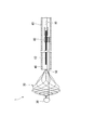
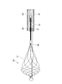
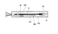
- FIG. 1 is a cross-sectional view of the treatment instrument 1.
- FIG. 2 is a partial cross-sectional view of the distal end portion of the treatment instrument 1.
- the side where the operation unit 70 is provided in the length direction of the treatment instrument 1 will be described as the base end side, and the side opposite to the base end side will be described as the front end side.
- the treatment instrument 1 includes an operation wire 10, a basket portion 20, a distal tip 30, a bundling portion 40, and a support member 50, each having a flexible sheath (hereinafter simply referred to as “sheath”). It is configured to be inserted in 60 so as to be able to advance and retreat.
- the operation wire 10 is connected to the operation unit 70 at the proximal end side, and is inserted through the sheath 60 so as to advance and retreat.
- a basket portion 20 is provided at the tip of the operation wire 10.
- the operation wire 10 is moved back and forth with respect to the sheath 60 by operation of the operation unit 70 described later.
- a stranded wire made of a plurality of metal wires is used as the operation wire 10.
- the basket portion 20 is located on the distal end side of the operation wire 10, and a plurality of basket wires 21 are bundled to form a basket shape.
- the basket portion 20 is configured by the eight basket wires 21, but the number of basket wires 21 may be set as appropriate in consideration of ease of taking in stones and difficulty in spilling stones.
- the plurality of basket wires 21 are elastic wires each having a spiral shape in a natural state and elastically deformable.
- the basket wire 21 is made of a highly elastic material such as a single wire or a stranded superelastic alloy.
- a material of the basket wire 21 for example, a nickel titanium alloy, stainless steel, a stainless alloy, or the like can be adopted.
- the basket wire 21 has a spiral shape as a whole in the length direction, and is formed so that the pitch in the axial direction of the spiral is short and the size in the radial direction (spiral winding diameter) is large on the distal end side. On the side, a gentle spiral shape is given compared to the tip side.
- each basket wire 21 has a distal end portion 22 fixed to a distal end tip 30, and a first base end portion (base end portion) 23 constituting the basket portion 20 is bundled by a binding portion 40. ing.
- Each basket wire 21 has a shape wound spirally around the central axis L connecting the tip 30 and the binding portion 40 in a natural state, and is configured to be elastically deformable.
- the central axis L of the basket portion 20 is a line connecting the point where the tip of the basket wire 21 is bundled and fixed by the tip 30 and the bundling portion 40 where the first base end portion 23 of the basket wire 21 is bundled. is there.
- Each basket wire 21 has the same spiral winding direction and the same winding shape, is arranged at equal intervals around the central axis L, and is bundled at the distal end portion 22 and the first proximal end portion 23.
- a basket is formed.
- the basket wire 21 is wound counterclockwise when viewed from the distal end portion 22 toward the first proximal end portion 23.
- the basket portion 20 in the natural state where no external force is applied, has a maximum diameter portion 27 closer to the tip portion 22 side than the intermediate portion in the length direction of the basket portion 20 as shown in FIGS.
- the first base end portion 23 side of the maximum diameter portion 27 is formed to have a gentle spiral shape with a larger pitch.
- the first base end portion 23 side with respect to the maximum diameter portion 27 functions as an intake portion 28 for taking in foreign matters such as stones into the basket portion 20.
- the foreign matter taken into the basket portion 20 functions as a storage portion 26 that is difficult to drop out of the basket portion 20.
- the tip 30 is provided on the tip side of the basket portion 20, and the tip portion 22 of the basket wire 21 is bundled and fixed.
- the tip 30 has a cylindrical portion 31 in which an insertion hole (not shown) is formed.
- the tip portions 22 of the plurality of basket wires 21 are inserted into the insertion holes of the cylindrical portion 31, and the tip portions 22 of the basket wires 21 are formed into a cylindrical shape by brazing, welding, caulking, resin welding, adhesive, and combinations thereof. It is fixed to the part 31.
- a substantially hemispherical protective portion 32 having a larger radius than the cylindrical portion 31 is provided on the distal end side of the cylindrical portion 31.
- the protection unit 32 is provided for the purpose of smoothly inserting the basket unit 20 by preventing the tip 22 of the basket wire 21 from being stuck or caught in the living tissue when the treatment instrument 1 is used.
- a distal end portion of a support member 50 described later is also inserted into and fixed to the cylindrical portion 31 of the distal tip 30.
- the bundling portion 40 is a portion where the first base end portions 23 of the plurality of basket wires 21 are bundled and fixed.
- the binding portion 40 includes a structure in which the basket wires 21 are fixed to each other by brazing, welding, caulking, resin welding, adhesive, and a combination thereof, and the outer peripheral side of the plurality of basket wires 21 is surrounded and fixed by a binding member. The structure to do can be adopted.
- the binding portion 40 is configured by inserting and fixing each basket wire 21 through the cylindrical binding member 41.
- the plurality of basket wires 21 have a linear portion 24 having a linear shape in a natural state on the proximal end side of the binding portion 40, that is, on the proximal end side of the first proximal end portion 23. .
- the straight portions 24 of the basket wires 21 are not fixed to each other in a bundled state but are provided to extend in the axial direction of the operation wire 10, and the base end 25 is connected to the distal end portion 11 of the operation wire 10.
- the operation wire 10 and the base end 25 of the basket wire 21 are respectively inserted and fixed in the substantially cylindrical first connecting portion 12.
- each basket wire 21 does not constitute the basket portion 20 and functions as a second operation wire portion (operation wire) 13 that advances and retracts following the advance and retreat operation of the operation wire 10. That is, in the basket wire 21, the tip portion 22 to the first base end portion 23 constitute the basket portion 20, and the straight portion 24 on the base end side from the binding portion 40 constitutes the second operation wire portion 13.
- the support member 50 is a wire having higher rigidity and elasticity than the basket wire 21 and is disposed so as to pass through the basket portion 20 along the central axis L of the basket portion 20 as shown in FIGS. 1 and 2.
- the central axis L of the basket portion 20 is arranged substantially coaxially with the central axis L ⁇ b> 10 of the operation wire 10.
- the distal end of the support member 50 is fixed to the cylindrical portion 31 of the distal tip 30.
- the length of the support member 50 is set such that the base end of the support member 50 is located in the sheath 60 even when the basket portion 20 protrudes from the distal end of the sheath 60 to the maximum extent.
- the support member 50 is arranged so that its own central axis does not coincide with the central axis of the basket portion 20 and the tip 30 and is substantially parallel to the central axis L of the basket portion 20. That is, the support member 50 is fixed to the cylindrical portion 31 on the radially outer side of the fixing portion of the plurality of basket wires 21 in the cylindrical portion 31 and is held at a position offset with respect to the central axis L of the basket portion 20.
- the support member 50 supports the basket portion 20 so as to keep the tip 30 positioned on the central axis L of the basket portion 20.
- the support member 50 has such a rigidity that it can be bent following a bending operation such as bending of the sheath 60 when stored in the sheath 60.
- the proximal end portion 51 of the support member 50 is disposed on the proximal end side with respect to the binding portion 40.
- the proximal end portion 51 is connected to the operation wire 10 so as to be slidable in the direction of the central axis L10 with respect to the operation wire 10 at a position closer to the proximal end than the binding portion 40.
- the base end portion 51 of the support member 50 is connected to the operation wire 10 via the connection member 80.
- the support member 50 is not fixed to the second operation wire portion 13 and the operation wire 10, and moves forward and backward in the longitudinal direction of the sheath 60 independently of the basket wire 21 and the operation wire 10 within the lumen of the sheath 60.
- connection member 80 is a substantially cylindrical member, and is formed with an insertion hole 81 into which the support member 50 is inserted and a through hole 82 into which the second operation wire portion 13 is inserted. Yes.
- the insertion hole 81 and the through hole 82 extend in the direction of the central axis L of the basket portion 20.
- the insertion hole 81 and the through hole 82 are formed in parallel.
- the through hole 82 has an opening diameter larger than the outer diameter of the bundle of the plurality of basket wires 21 constituting the second operation wire portion 13, and the second operation wire portion 13 is inserted into the through hole 82 so as to be able to advance and retract. ing.
- the base end portion 51 of the support member 50 is inserted into the insertion hole 81 and is fixed by brazing, welding, caulking, resin welding, adhesive, or a combination thereof.
- the support member 50 can be along the operation wire on the proximal end side with respect to the binding portion 40 and can be kept away from each other. .
- the sheath 60 is inserted into the endoscope insertion portion 101 (FIG. 5).
- the sheath 60 can be configured by appropriately selecting or combining known resin materials such as fluororesin and thermoplastic elastomer, a coil sheath formed by winding a metal wire, a blade using a metal wire, and the like.
- the central axis L of the basket portion 20 is disposed at least in parallel with the central axis L60 of the sheath 60. More preferably, the central axis L of the basket portion 20 is disposed on the central axis L60 of the sheath 60.
- the operation unit 70 is provided at the proximal end portion of the treatment instrument 1 as shown in FIG.
- the operation unit 70 includes an operation main body 71, a shaft 72, and a slider 73.
- the operation main body 71 is provided on the proximal end side of the sheath 60.
- a through passage 71a penetrating in the axial direction of the sheath 60 is formed inside.
- the operation main body 71 is connected to the base end portion 61 of the sheath 60 so that the through passage 71a and the inside of the sheath 60 communicate with each other.
- the shaft 72 is inserted through the through passage 71 a, and the distal end of the shaft 72 is connected to the proximal end 14 of the operation wire 10 by the second connecting portion 15.
- the base end of the shaft 72 protrudes from the base end side of the through passage 71 a and is fixed to the slider 73.
- the slider 73 has a grip 74 that can be gripped by the operator.
- the shaft 72 is provided so as to be able to advance and retreat in the through passage 71 a with respect to the operation main body 71.
- the operation main body 71 further has a liquid feeding port 75.
- the liquid feeding port 75 is formed so as to communicate with the through passage 71a, and is configured so that, for example, a known syringe or pump can be connected.
- the through passage 71a has an opening diameter capable of feeding liquid in a state where the shaft 72 is inserted.
- An enlarged diameter portion 71b having a diameter larger than that of the distal end side is formed in the through passage 71a closer to the proximal end than the liquid feeding port 75, and a step portion 71c is formed between the enlarged diameter portion 71b and the distal end side of the penetration passage 71a. Is formed.
- a fitting member 76 that is formed in a cylindrical shape along the shape of the inner peripheral surface of the enlarged diameter portion 71 b is inserted and fitted into the enlarged diameter portion 71 b from the proximal end side of the operation main body 71.
- An O-ring 77 is externally provided on the outer periphery of the shaft 72, and the O-ring 77 is disposed between the fitting member 76 and the stepped portion 71c.
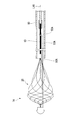
- FIGS. 3 and 4 are cross-sectional views showing the distal end portion of the treatment instrument 1.
- FIG. 2 is a view showing a state in which the basket portion 20 is pushed out from the distal end of the sheath 60.
- the basket portion 20 In a state where the basket portion 20 is pushed out from the distal end of the sheath 60 and no external force is applied to the basket portion 20, the basket portion 20 has a basic shape previously applied as shown in FIG. 2 by the restoring force of the basket wire 21. Form a basket.
- the base end portion 51 of the support member 50 is connected to the connection member 80 at a substantially intermediate position of the second operation wire portion 13 (an intermediate position between the binding portion 40 and the first connecting portion 12) within the lumen of the sheath 60. Is connected to the second operation wire portion 13.
- the basket portion 20 is configured by the spiral basket wire 21 described above, when protruding from the sheath 60, a basket shape is formed which is easy to capture and hold foreign matter. Further, when the basket portion 20 is drawn into the sheath 60, the diameter of the basket portion 20 can be reduced smoothly and can be easily stored in the sheath 60. When the basket portion 20 moves back and forth with respect to the sheath 60, the support member 50 can support the central axis L of the basket portion 20 while keeping it parallel to the central axis L60 of the sheath 60.
- FIG. 3 shows a state where the basket portion 20 is stored in the sheath 60.
- the basket portion 20 In a state in which the basket portion 20 is housed in the sheath 60, the basket portion 20 is pressed against the inner wall of the lumen of the sheath 60 and elastically deformed, and the diameter thereof is reduced from the basic shape shown in FIG.
- the diameter of the basket portion 20 is reduced, the overall length of the basket portion 20 relatively extends in the direction of the central axis L, and the tip 30 moves in a direction away from the binding portion 40.
- the support member 50 is pulled toward the tip side, and the length of the portion disposed in the basket portion 20 increases.
- the connection member 80 moves relative to the distal end side with respect to the second operation wire portion 13 in the through hole 82, and the binding portion 40. Get closer to. That is, the base end portion 51 of the support member 50 moves toward the distal end side while maintaining a state of being aligned along the second operation wire portion 13 and parallel to the diameter of the basket portion 20.
- the support member 50 functions as a core material that supports the basket portion 20 while keeping the tip 30 positioned on the central axis L of the basket portion 20. For this reason, the plurality of basket wires 21 are accommodated in the sheath 60 in a state of being elastically deformed substantially linearly along the support member 50.
- FIG. 4 is a diagram illustrating a state in which the basket portion 20 has a shorter overall length than the reference shape of FIG. 2 due to an external force applied to the basket portion 20 in a state where the basket portion 20 protrudes from the distal end of the sheath 60.
- the distal end side is larger than the maximum diameter portion 27 of the basket portion 20 and the proximal end side by the luminal tissue.
- Such a shape can be obtained when a pressing force is applied.
- the tip 30 moves to a position closer to the binding portion 40 than in the reference shape.
- a force that moves in the proximal direction acts on the support member 50, and the proximal end portion 51 of the support member 50 approaches the first connecting portion 12. Since the base end portion 51 of the support member 50 is fixed to the connection member 80, the connection member 80 moves relative to the base end side with respect to the second operation wire portion 13 in the insertion hole 81 and moves to the second connection portion 15. Get closer to. That is, the base end portion 51 of the support member 50 moves to the base end side while maintaining a state of being aligned in parallel with the second operation wire portion 13 as the overall length of the basket portion 20 decreases.
- the support member 50 functions as a core material that supports the basket portion 20 so as to keep the tip 30 positioned on the central axis L of the basket portion 20. For this reason, in the basket portion 20, the state in which the tip 30 is positioned on the central axis L is maintained by the support member 50, and the state in which a space is formed in the basket portion 20 is maintained.
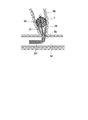
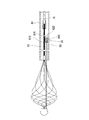
- FIG. 1 is a diagram showing how the treatment tool 1 and the endoscope apparatus 100 are used.
- the treatment tool 1 according to the present embodiment is used by being inserted into an endoscope insertion portion 101 of an endoscope apparatus 100 as shown in FIG.
- the operator inserts the endoscope insertion portion 101 of the endoscope apparatus 100 into the digestive tract from the mouth, for example, and confirms with an imaging unit (not shown) in FIG. 6.
- the distal end of the endoscope insertion portion 101 is inserted up to the duodenum Dd.
- the operator inserts the treatment instrument 1 into the endoscope insertion portion 101 of the endoscope apparatus 100 from the insertion port 103 (see FIG. 5), and moves the distal end portion 62 of the sheath 60 as shown in FIG. It protrudes from the tip of the endoscope insertion portion 101.
- the endoscope operation unit 102 of the endoscope apparatus 100 When projecting the distal end portion 62 of the sheath 60, the endoscope operation unit 102 of the endoscope apparatus 100 is operated, and the sheath 60 is raised by an elevator (not shown) provided in the endoscope insertion unit 101. Let me rise. The operator advances the sheath 60 with respect to the endoscope insertion portion 101 to enter the bile duct BD, and inserts it until the distal end portion 62 of the sheath 60 reaches the vicinity of the calculus T generated in the bile duct BD.
- the operator grasps the grasping portion 74 and pushes the slider 73 toward the distal end side to cause the basket portion 20 to protrude from the distal end portion 62 of the sheath 60.
- the slider 73 is pushed in until the slider 73 comes into contact with the proximal end portion of the operation main body 71, the binding portion 40 protrudes from the distal end portion 62 of the sheath 60.
- the calculus T is located closer to the proximal end side than the maximum diameter portion 27 of the basket portion 20.
- the operator pulls the slider 73 toward the proximal end side to retract the basket portion 20 into the distal end portion 62 of the sheath 60.
- the separation distance between the basket wires 21 is wide at the intake portion 28 on the proximal end side than the maximum diameter portion 27. Therefore, when the calculus T is in contact with the basket wire 21 of the take-in portion 28 and the basket portion 20 is pulled toward the proximal end, the basalt T of the take-up portion 28 is pushed and widened by the calculus T, and the calculus T is It is captured in the part 20.
- the operator moves the slider 73 further to the proximal end side and stores the intake portion 28 in the sheath 60. At this time, the calculus T is held by the plurality of basket wires 21 while being stored in the storage portion 26 of the basket portion 20. Subsequently, the operator retracts the endoscope insertion portion 101, discharges the basket portion 20 outside the body, and discharges the calculus T outside the body to be collected.
- the support member 50 advances and retreats along the second operation wire portion 13 by the connecting member 80.
- the basket portion 20 is supported by the support member 50 while securing an internal space.
- the calculus T is removed from the bile duct BD by the series of procedures described above.
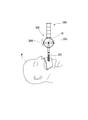
- a calculus T larger than the opening of the duodenal papilla Dp is stored in the basket portion 20
- the treatment tool 1 is incarcerated in the bile duct BD, and the basket portion 20 is It cannot be pulled into the duodenum Dd side.
- a treatment using a calculus crusher as disclosed in Patent Document 2 is performed.
- the operator cuts the sheath 60 and the operation wire 10 at a position in the vicinity of the operation unit 70 (position indicated by an arrow A in FIG. 5), and the endoscope insertion unit 101 and the sheath 60 are disconnected. Remove from the body. When the endoscope insertion portion 101 and the sheath 60 are removed, the operation wire 10 and the support member 50 are exposed in the duodenum Dd as shown in FIG. At this time, in the conventional treatment instrument, since the base end portion of the support member is not connected to the operation wire, it extends substantially linearly by its own rigidity independently of the bending of the operation wire. On the other hand, in the present embodiment, since the base end portion 51 of the support member 50 is connected along the second operation wire portion 13 by the connection member 80, the support member 50 follows the curvature of the second operation wire portion 13. And curved.
- the surgeon inserts the proximal end portion of the cut operation wire 10 that is outside the mouth of the patient P into the coil sheath 201 of the calculus crusher 200, and the coil sheath 201 is inserted. Insert into the body. The coil sheath 201 is inserted along the operation wire 10 to the duodenum Dd and the duodenal papilla Dp, and is inserted until it reaches the basket portion 20 as shown in FIG.
- the surgeon can connect the proximal end portion of the support member 50 as shown in FIG. 51 can be smoothly inserted into the coil sheath 201 together with the second operation wire portion 13.
- the surgeon inserts the cut proximal end portion of the operation wire 10 into the insertion hole (not shown) of the winding shaft 203 of the operation unit 202 of the calculus crusher 200.
- the handle 204 is rotated, the winding shaft 203 is rotated, and the operation wire 10 is wound.
- the operation wire 10 is pulled to the proximal end side, and a force drawn into the coil sheath 201 acts on the basket portion 20, and the calculus T is sandwiched by the basket portion 20.
- the calculus T is clamped and pulverized by the plurality of basket wires 21.
- the calculus T is crushed, the incarceration is eliminated, so the coil sheath 201 and the cut treatment tool 1 are removed from the body.
- the treatment instrument 1 is connected to the operation wire 10 in a state in which the proximal end portion 51 of the support member 50 is movable relative to the second operation wire portion 13.
- the support member 50 fulfills the original function of supporting the basket portion 20 during normal use.
- the base end portion 51 of the support member 50 is disposed along the second operation wire portion 13 even after the cut sheath 60 is removed. It can be smoothly inserted into the coil sheath 201 of 200, and the emergency crushing treatment of the calculus T can be performed quickly.
- the base end side of the basket wire 21 is provided with the straight portion 24 on the base end side with respect to the binding portion 40, and the bundle of the straight portion 24 functions as the second operation wire portion 13.
- the bundling portion and the operation wire may be directly connected.
- the operation member 10 is inserted into the through hole 82 on the proximal end side of the connection member 80 from the binding portion, and the connection member 80 and the proximal end portion 51 of the support member 50 are changed with the shape change of the basket portion 20.
- the structure moves relative to the operation wire 10 in the longitudinal direction.
- the basket portion of the present invention is not limited to the shape shown in the above embodiment, and may be any structure as long as it has a basket shape that includes a plurality of basket wires and can capture foreign matter.
- connection member of the present embodiment is not limited to the above-described form, and the base end portion of the support member 50 is the operation wire so that the support member 50 can move relative to the operation wire 10 in the longitudinal direction. 10 may be connected.
- the connection member may be fixed at a predetermined position on the operation wire 10 side according to the length of the support member 50, and the support member 50 may be relatively movable with respect to the connection member.
- the following configurations shown in FIGS. 12 to 23 can be adopted as the connection member.
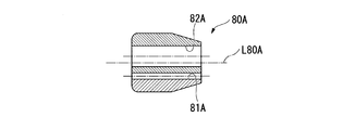
- (First modification of connecting member) 12 and 13 are views showing a first modification of the connection member.
- the insertion hole 81A and the through hole 82A extend in parallel to the central axis L80A of the connection member 80A and are formed near the central axis L80A.
- the second operation wire portion 13 (operation wire 10) and the base end portion of the support member 50 are disposed near the central axis L60 in the sheath 60, and a sufficient gap is provided between the sheath 60 and the lumen. Therefore, the operation wire 10 can be smoothly advanced and retracted with respect to the sheath 60.
- a curved surface is formed at the distal end of the connecting member 80A, and the connecting member 80A can be smoothly advanced and retracted within the lumen of the sheath 60.
- connection member 80A of the present modification is different from the connection member 80 of the first embodiment in that the outer diameter on the base end side is formed smaller than the outer diameter on the distal end side.
- the connecting member 80A has a proximal end side while ensuring a length necessary for stably maintaining the state in which the second operation wire portion 13 (operation wire 10) and the proximal end portion 51 of the support member 50 are parallel to each other.
- the outer diameter is configured to be small.
- connection member 80 ⁇ / b> A of the present modification has the support member 50 and the operation wire 10 in parallel with the base end portion 51 of the support member 50 being along the operation wire 10.
- the base end portion 51 of the support member 50 can be connected to the operation wire 10 so as to be relatively movable in the axial direction while maintaining the operation wire 10.
- the connecting member 80A can smoothly operate the operation wire 10 to advance and retract with respect to the sheath 60 while suppressing sliding resistance with the lumen of the sheath 60.
- the connecting member 80A can be smoothly inserted while suppressing sliding resistance in the coil sheath 201.
- connection member 80B of the present modification includes a substantially cylindrical main body (holding portion) 83B and an insertion tube 85B protruding in the direction of the central axis L80B from the distal end surface 84B of the main body 83B.
- the main body 83B and the insertion tube 85B are integrally formed.
- an insertion hole 81B and a through hole 82B are formed so as to extend in parallel to the central axis L80B of the connecting member 80B and close to the central axis L80B.
- the through hole 82B has an opening diameter that is large enough to allow the second operation wire portion 13 to advance and retreat, and the second operation wire portion 13 is inserted therethrough.
- the insertion hole 81B is formed in communication with the main body portion 83B and the insertion tube 85B.
- the insertion hole 81B has an opening diameter through which the proximal end portion 51 of the support member 50 can be inserted and fixed.
- connection member 80 ⁇ / b> B of the present modification keeps the support member 50 and the operation wire parallel with the base end portion 51 of the support member 50 being along the operation wire 10.
- the base end portion 51 of the support member 50 can be connected to the operation wire 10 so as to be relatively movable in the axial direction.
- the length of the portion of the through hole 82B through which the operation wire 10 is inserted so as to be able to advance and retract is set short in the direction of the central axis L80B. It is possible to reduce the frictional resistance by reducing the contact area.
- the connecting member 80B from obstructing the advance / retreat operation of the operation wire 10 with respect to the sheath 60.
- the insertion hole 81B for fixing the support member 50 is formed in the main body portion 83B and the insertion tube 85B, the state where the operation wire 10 and the base end portion 51 of the support member 50 are in parallel is stably maintained. The necessary length is secured. Since the outer diameter of the insertion tube 85B is smaller than the outer diameter of the main body portion 83B, a sufficient gap is secured between the insertion tube 85B and the lumen of the sheath 60, so that the connection member 80B is the sheath of the operation wire 10. It is possible to prevent the advance / retreat operation for 60 from being hindered.
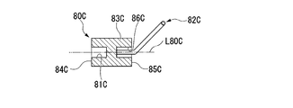
- connection member 80 ⁇ / b> C of this modification is different from the first embodiment in the configuration of the insertion hole through which the operation wire 10 is inserted.
- the connection member 80C has a substantially cylindrical main body (holding portion) 83C and an insertion ring 82C fixed to the main body 83C.
- the main body portion 83C is open to the distal end surface 84C and is formed coaxially with the first insertion hole 81C formed on the central axis L80C of the main body portion 83C and the proximal end surface 85C.
- Second insertion hole 86C Second insertion hole 86C.
- the base end portion 51 of the support member 50 is inserted and fixed in the first insertion hole 81C.
- the insertion ring 82C has a loop portion (sliding portion) 87C formed of a linear member, and the loop portion 87C is bent to be inclined with respect to the end portion.
- the insertion ring 82 ⁇ / b> C is fixed to the main body portion 83 ⁇ / b> C by inserting and fixing the end portion of the linear member through the second insertion hole 86 ⁇ / b> C. As shown in FIGS.
- the loop portion 87C of the insertion ring 82C extends outward from the outer periphery of the main body portion 83C when viewed from the direction orthogonal to the central axis L80C, and the loop extends in the direction of the central axis L80C. It arrange
- the support member 50 and the operation wire 10 are connected by inserting the second operation wire portion 13 through the loop portion 87C of the insertion ring 82C.
- connection member 80 ⁇ / b> C operates while maintaining the support member 50 and the operation wire 10 in parallel with the base end portion 51 of the support member 50 being along the operation wire 10.
- the proximal end portion 51 of the support member 50 can be connected to the wire 10 so as to be relatively movable in the axial direction.
- the second operation wire portion 13 is inserted into the loop portion 87C of the insertion ring 82C formed of a linear member, the contact area between the loop portion 87C and the second operation wire portion 13 is suppressed, and the friction resistance Can be kept low.
- the connection member 80C can be prevented from obstructing the advance / retreat operation of the operation wire 10 with respect to the sheath 60.
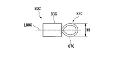
- FIG. 20 is a diagram illustrating a fourth modification of the connection member.
- the connecting member 80D of the present modified example is different from the connecting member 80C of the third modified example in the shape of the loop portion.
- the width (W2) of the loop portion (sliding portion) 87D in the direction orthogonal to the central axis L80D is smaller than the width W1 of the loop portion 87C of the connection member 80C of the third modified example.
- the width W1 of the loop portion 87C of the third modification is substantially equal to the diameter of the main body (holding portion) 83C, whereas the width W2 of the loop portion 87D of this modification is smaller than the diameter of the main body 83D. .
- connection member 80D operates while maintaining the support member 50 and the operation wire 10 in parallel with the base end portion 51 of the support member 50 being along the operation wire 10.
- the proximal end portion 51 of the support member 50 can be connected to the wire 10 so as to be relatively movable in the axial direction.
- the contact area between the loop portion 87D and the second operation wire portion 13 can be suppressed, and the frictional resistance can be suppressed low.
- the connection member 80D can be prevented from obstructing the advance / retreat operation of the operation wire 10 with respect to the sheath 60.
- FIG. 21 is a diagram illustrating a fifth modification of the connection member.
- the connection member 80E of this modification is different from the connection member 80C of the third modification in the shapes of the loop portion 87E, the main body 83E, and the connection portion.
- a linear portion 871 having a predetermined length (for example, 20 mm) is provided between the loop portion (sliding portion) 87E and the main body portion 83E, so that the loop portion 87E and the main body portion 83E are provided. It is configured to have a certain distance.
- the length of the straight line portion 871 may be set so that the distance between the loop portion 87E and the main body portion 83E is long as long as the sliding of the loop portion 87E and the basket portion 20 is not affected. In this modification, the length of the straight line portion 871 is set longer than the length of the loop portion 87E and the main body portion 83E. As shown in FIG. 22, the loop portion 87E and the straight portion 871 form a large-diameter loop in the middle portion of the wire, and at least a portion 872 of the wire of the straight portion 871 is fixed by brazing or adhesive. It is formed with.
- the basket wire 21 Normally, when the operation wire is pulled in a state where the sheath 60 in the vicinity of the connecting member is curved, the basket wire 21 approaches the inside of the sheath 60 on the proximal side of the curved portion of the sheath 60 as shown in FIG. . On the other hand, a force for returning to the central axis side of the sheath 60 acts on the loop portion. Due to this behavior, the basket wire 21 receives a force in the direction of arrow F1 from the loop portion 87E. Further, the basket wire 21 approaches the outer side of the bending of the sheath 60 on the distal end side of the sheath bending portion, while the main body portion 83E tries to return to the central axis side of the sheath 60.
- FIG. 24 is a partial cross-sectional view showing the distal end portion of the treatment instrument 1A.
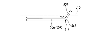
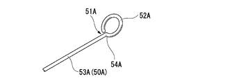
- FIG. 25 is a side view of the base end portion 51A of the support member 50A of the present embodiment.
- FIG. 26 is a view of the support member 50A according to the present embodiment as viewed from the distal end side.
- FIG. 27 is a perspective view of the base end portion 51A of the support member 50A of the present embodiment.
- the treatment instrument 1A of the present embodiment has a loop portion (sliding portion) 52A at the base end portion 51A of the support member 50A instead of the connection member 80 of the first embodiment. That is, as shown in FIG. 27, the support member 50 ⁇ / b> A forms a loop part 52 ⁇ / b> A wound around the base end part 51 ⁇ / b> A, and the loop part 52 ⁇ / b> A functions as an insertion path for the operation wire 10.
- a bent portion 54A is provided between the linear portion 53A and the loop portion 52A of the support member 50A, and the loop portion 52A has a support member when viewed from a direction orthogonal to the axial direction as shown in FIG. It arrange
- the angle ⁇ of the bent portion 54A may be a right angle.
- the angle ⁇ of the bent portion 54A is an obtuse angle
- the size in the direction perpendicular to the axis of the base end portion 51A of the support member 50A can be reduced.
- the overall diameter of the support member 50A and the operation wire 10 in a state where the operation wire 10 is inserted can be reduced. Therefore, when the angle ⁇ of the bent portion 54A is an obtuse angle, the support member 50A and the operation wire 10 can be smoothly moved in the sheath 60.
- loop portion 52A is not limited to the above form as long as the operation wire 10 can be inserted.
- a loop portion (sliding portion) 52B may be wound in multiple (double in the example shown in FIG. 28).
- the curved shape of the loop portion is not limited to a circular shape.
- the support member 50 and the operation wire 10 are kept parallel to each other with the base end portion 51 of the support member 50 being along the operation wire, while the operation wire 10 is kept in parallel.
- the base end portion 51 of the support member 50 can be connected so as to be relatively movable in the axial direction.
- the support member 50 and the operation wire 10 can be connected with a simple configuration in which the loop portion 52A is formed at the base end portion 51A of the support member 50A.
Priority Applications (4)
| Application Number | Priority Date | Filing Date | Title |
|---|---|---|---|
| JP2016567052A JP6081682B1 (ja) | 2015-05-19 | 2016-05-13 | 内視鏡用処置具 |
| EP16796425.3A EP3298973B1 (en) | 2015-05-19 | 2016-05-13 | Endoscopic treatment instrument |
| CN201680003581.1A CN107072682B (zh) | 2015-05-19 | 2016-05-13 | 内窥镜用处置器具 |
| US15/494,116 US10478223B2 (en) | 2015-05-19 | 2017-04-21 | Endoscopic treatment tool |
Applications Claiming Priority (2)
| Application Number | Priority Date | Filing Date | Title |
|---|---|---|---|
| JP2015101766 | 2015-05-19 | ||
| JP2015-101766 | 2015-05-19 |
Related Child Applications (1)
| Application Number | Title | Priority Date | Filing Date |
|---|---|---|---|
| US15/494,116 Continuation US10478223B2 (en) | 2015-05-19 | 2017-04-21 | Endoscopic treatment tool |
Publications (1)
| Publication Number | Publication Date |
|---|---|
| WO2016186032A1 true WO2016186032A1 (ja) | 2016-11-24 |
Family
ID=57320055
Family Applications (1)
| Application Number | Title | Priority Date | Filing Date |
|---|---|---|---|
| PCT/JP2016/064315 WO2016186032A1 (ja) | 2015-05-19 | 2016-05-13 | 内視鏡用処置具 |
Country Status (5)
| Country | Link |
|---|---|
| US (1) | US10478223B2 (zh) |
| EP (1) | EP3298973B1 (zh) |
| JP (1) | JP6081682B1 (zh) |
| CN (1) | CN107072682B (zh) |
| WO (1) | WO2016186032A1 (zh) |
Families Citing this family (2)
| Publication number | Priority date | Publication date | Assignee | Title |
|---|---|---|---|---|
| JP2020062318A (ja) * | 2018-10-19 | 2020-04-23 | 朝日インテック株式会社 | カテーテル |
| CN109363747A (zh) * | 2018-12-20 | 2019-02-22 | 王欣 | 一种气管镜介入牵引附件 |
Citations (4)
| Publication number | Priority date | Publication date | Assignee | Title |
|---|---|---|---|---|
| JPH06296617A (ja) * | 1993-04-16 | 1994-10-25 | Olympus Optical Co Ltd | バスケット鉗子 |
| US5527326A (en) * | 1992-12-29 | 1996-06-18 | Thomas J. Fogarty | Vessel deposit shearing apparatus |
| JP2011526188A (ja) * | 2008-06-25 | 2011-10-06 | セレウ,ラフィック | 折り畳まれた位置から係蹄ループ又は焼灼ループに半径方向に展開可能な手術用採取装置 |
| WO2015087952A1 (ja) * | 2013-12-12 | 2015-06-18 | オリンパス株式会社 | バスケット型把持鉗子 |
Family Cites Families (9)
| Publication number | Priority date | Publication date | Assignee | Title |
|---|---|---|---|---|
| IT1126526B (it) * | 1979-12-07 | 1986-05-21 | Enrico Dormia | Estrattore chirurgico per asportare corpi estranei che si trovano nelle vie naturali del corpo umano,come calcoli e simili |
| GB2116046B (en) * | 1982-03-04 | 1985-05-22 | Wolf Gmbh Richard | Apparatus for disintegrating and removing calculi |
| US4706671A (en) * | 1985-05-02 | 1987-11-17 | Weinrib Harry P | Catheter with coiled tip |
| JPH06133978A (ja) * | 1992-10-22 | 1994-05-17 | Olympus Optical Co Ltd | 結石破砕装置 |
| DE69631121T2 (de) * | 1995-02-02 | 2004-08-19 | Boston Scientific Corp., Natick | Chirurgischer extraktor mit einem drahtkorb |
| US20030187495A1 (en) * | 2002-04-01 | 2003-10-02 | Cully Edward H. | Endoluminal devices, embolic filters, methods of manufacture and use |
| US7128752B2 (en) * | 2002-12-23 | 2006-10-31 | Syntheon, Llc | Emboli and thrombi filter device and method of using the same |
| CN102970938A (zh) * | 2010-04-13 | 2013-03-13 | 访问点技术公司 | 栓塞物质切除捕集装置 |
| JP5252606B2 (ja) * | 2011-04-13 | 2013-07-31 | オリンパスメディカルシステムズ株式会社 | 内視鏡用処置具 |
-
2016
- 2016-05-13 WO PCT/JP2016/064315 patent/WO2016186032A1/ja active Application Filing
- 2016-05-13 EP EP16796425.3A patent/EP3298973B1/en active Active
- 2016-05-13 CN CN201680003581.1A patent/CN107072682B/zh active Active
- 2016-05-13 JP JP2016567052A patent/JP6081682B1/ja active Active
-
2017
- 2017-04-21 US US15/494,116 patent/US10478223B2/en active Active
Patent Citations (4)
| Publication number | Priority date | Publication date | Assignee | Title |
|---|---|---|---|---|
| US5527326A (en) * | 1992-12-29 | 1996-06-18 | Thomas J. Fogarty | Vessel deposit shearing apparatus |
| JPH06296617A (ja) * | 1993-04-16 | 1994-10-25 | Olympus Optical Co Ltd | バスケット鉗子 |
| JP2011526188A (ja) * | 2008-06-25 | 2011-10-06 | セレウ,ラフィック | 折り畳まれた位置から係蹄ループ又は焼灼ループに半径方向に展開可能な手術用採取装置 |
| WO2015087952A1 (ja) * | 2013-12-12 | 2015-06-18 | オリンパス株式会社 | バスケット型把持鉗子 |
Also Published As
| Publication number | Publication date |
|---|---|
| US20170224380A1 (en) | 2017-08-10 |
| EP3298973B1 (en) | 2021-01-13 |
| EP3298973A4 (en) | 2018-12-12 |
| JPWO2016186032A1 (ja) | 2017-06-22 |
| CN107072682A (zh) | 2017-08-18 |
| JP6081682B1 (ja) | 2017-02-15 |
| EP3298973A1 (en) | 2018-03-28 |
| US10478223B2 (en) | 2019-11-19 |
| CN107072682B (zh) | 2020-05-12 |
Similar Documents
| Publication | Publication Date | Title |
|---|---|---|
| US6264664B1 (en) | Surgical basket devices | |
| JP5252606B2 (ja) | 内視鏡用処置具 | |
| AU2007211263B2 (en) | Wire guide having distal coupling tip for attachment to a previously introduced wire guide | |
| JP6095870B2 (ja) | 内視鏡用処置具 | |
| JP5861005B2 (ja) | バスケット型把持鉗子 | |
| US10045762B2 (en) | Dilation device and expandable covering for a dilation instrument | |
| JP6081682B1 (ja) | 内視鏡用処置具 | |
| JP2016101315A (ja) | 医療用デバイス | |
| JP2011019937A (ja) | バスケット鉗子 | |
| JP6389683B2 (ja) | 医療用デバイス | |
| JP6569206B2 (ja) | 医療用バスケット型処置器具 | |
| JP6124782B2 (ja) | バスケット型把持鉗子 | |
| JP2018191986A (ja) | ガイドワイヤ案内手段及び該ガイドワイヤ案内手段を備えたバスケット型内視鏡装置用処置具 | |
| JP6203034B2 (ja) | 医療用処置具 | |
| JP6908044B2 (ja) | 医療用器具 | |
| JP2006239139A (ja) | 内視鏡用処置具 | |
| JP7296178B2 (ja) | 医療用デバイス | |
| JP6788689B2 (ja) | バスケット型処置具 | |
| JP2016059716A (ja) | バスケットカテーテル | |
| JP6313183B2 (ja) | ガイドワイヤ | |
| JP4874934B2 (ja) | 生体組織採取具 | |
| JP2019080782A (ja) | バスケットカテーテル | |
| JP7006604B2 (ja) | 医療用器具 | |
| JP2024508891A (ja) | 医療デバイス管理システムを含む医療デバイス | |
| JP2022102156A (ja) | 医療デバイス |
Legal Events
| Date | Code | Title | Description |
|---|---|---|---|
| ENP | Entry into the national phase |
Ref document number: 2016567052 Country of ref document: JP Kind code of ref document: A |
|
| 121 | Ep: the epo has been informed by wipo that ep was designated in this application |
Ref document number: 16796425 Country of ref document: EP Kind code of ref document: A1 |
|
| NENP | Non-entry into the national phase |
Ref country code: DE |
|
| WWE | Wipo information: entry into national phase |
Ref document number: 2016796425 Country of ref document: EP |