WO2016181590A1 - ボールジョイントおよびボールジョイントの製造方法 - Google Patents
ボールジョイントおよびボールジョイントの製造方法 Download PDFInfo
- Publication number
- WO2016181590A1 WO2016181590A1 PCT/JP2016/001101 JP2016001101W WO2016181590A1 WO 2016181590 A1 WO2016181590 A1 WO 2016181590A1 JP 2016001101 W JP2016001101 W JP 2016001101W WO 2016181590 A1 WO2016181590 A1 WO 2016181590A1
- Authority
- WO
- WIPO (PCT)
- Prior art keywords
- ball
- ball joint
- welded
- shaft
- welding
- Prior art date
- Legal status (The legal status is an assumption and is not a legal conclusion. Google has not performed a legal analysis and makes no representation as to the accuracy of the status listed.)
- Ceased
Links
Images




Classifications
-
- F—MECHANICAL ENGINEERING; LIGHTING; HEATING; WEAPONS; BLASTING
- F16—ENGINEERING ELEMENTS AND UNITS; GENERAL MEASURES FOR PRODUCING AND MAINTAINING EFFECTIVE FUNCTIONING OF MACHINES OR INSTALLATIONS; THERMAL INSULATION IN GENERAL
- F16C—SHAFTS; FLEXIBLE SHAFTS; ELEMENTS OR CRANKSHAFT MECHANISMS; ROTARY BODIES OTHER THAN GEARING ELEMENTS; BEARINGS
- F16C11/00—Pivots; Pivotal connections
- F16C11/04—Pivotal connections
- F16C11/06—Ball-joints; Other joints having more than one degree of angular freedom, i.e. universal joints
- F16C11/0604—Construction of the male part
- F16C11/0609—Construction of the male part made from two or more parts
-
- B—PERFORMING OPERATIONS; TRANSPORTING
- B23—MACHINE TOOLS; METAL-WORKING NOT OTHERWISE PROVIDED FOR
- B23K—SOLDERING OR UNSOLDERING; WELDING; CLADDING OR PLATING BY SOLDERING OR WELDING; CUTTING BY APPLYING HEAT LOCALLY, e.g. FLAME CUTTING; WORKING BY LASER BEAM
- B23K31/00—Processes relevant to this subclass, specially adapted for particular articles or purposes, but not covered by any single one of main groups B23K1/00 - B23K28/00
- B23K31/02—Processes relevant to this subclass, specially adapted for particular articles or purposes, but not covered by any single one of main groups B23K1/00 - B23K28/00 relating to soldering or welding
-
- F—MECHANICAL ENGINEERING; LIGHTING; HEATING; WEAPONS; BLASTING
- F16—ENGINEERING ELEMENTS AND UNITS; GENERAL MEASURES FOR PRODUCING AND MAINTAINING EFFECTIVE FUNCTIONING OF MACHINES OR INSTALLATIONS; THERMAL INSULATION IN GENERAL
- F16C—SHAFTS; FLEXIBLE SHAFTS; ELEMENTS OR CRANKSHAFT MECHANISMS; ROTARY BODIES OTHER THAN GEARING ELEMENTS; BEARINGS
- F16C11/00—Pivots; Pivotal connections
- F16C11/04—Pivotal connections
- F16C11/06—Ball-joints; Other joints having more than one degree of angular freedom, i.e. universal joints
- F16C11/0619—Ball-joints; Other joints having more than one degree of angular freedom, i.e. universal joints the female part comprising a blind socket receiving the male part
- F16C11/0623—Construction or details of the socket member
- F16C11/0628—Construction or details of the socket member with linings
- F16C11/0633—Construction or details of the socket member with linings the linings being made of plastics
-
- F—MECHANICAL ENGINEERING; LIGHTING; HEATING; WEAPONS; BLASTING
- F16—ENGINEERING ELEMENTS AND UNITS; GENERAL MEASURES FOR PRODUCING AND MAINTAINING EFFECTIVE FUNCTIONING OF MACHINES OR INSTALLATIONS; THERMAL INSULATION IN GENERAL
- F16C—SHAFTS; FLEXIBLE SHAFTS; ELEMENTS OR CRANKSHAFT MECHANISMS; ROTARY BODIES OTHER THAN GEARING ELEMENTS; BEARINGS
- F16C11/00—Pivots; Pivotal connections
- F16C11/04—Pivotal connections
- F16C11/06—Ball-joints; Other joints having more than one degree of angular freedom, i.e. universal joints
- F16C11/0685—Manufacture of ball-joints and parts thereof, e.g. assembly of ball-joints
-
- F—MECHANICAL ENGINEERING; LIGHTING; HEATING; WEAPONS; BLASTING
- F16—ENGINEERING ELEMENTS AND UNITS; GENERAL MEASURES FOR PRODUCING AND MAINTAINING EFFECTIVE FUNCTIONING OF MACHINES OR INSTALLATIONS; THERMAL INSULATION IN GENERAL
- F16C—SHAFTS; FLEXIBLE SHAFTS; ELEMENTS OR CRANKSHAFT MECHANISMS; ROTARY BODIES OTHER THAN GEARING ELEMENTS; BEARINGS
- F16C11/00—Pivots; Pivotal connections
- F16C11/04—Pivotal connections
- F16C11/06—Ball-joints; Other joints having more than one degree of angular freedom, i.e. universal joints
- F16C11/0614—Ball-joints; Other joints having more than one degree of angular freedom, i.e. universal joints the female part of the joint being open on two sides
-
- F—MECHANICAL ENGINEERING; LIGHTING; HEATING; WEAPONS; BLASTING
- F16—ENGINEERING ELEMENTS AND UNITS; GENERAL MEASURES FOR PRODUCING AND MAINTAINING EFFECTIVE FUNCTIONING OF MACHINES OR INSTALLATIONS; THERMAL INSULATION IN GENERAL
- F16C—SHAFTS; FLEXIBLE SHAFTS; ELEMENTS OR CRANKSHAFT MECHANISMS; ROTARY BODIES OTHER THAN GEARING ELEMENTS; BEARINGS
- F16C11/00—Pivots; Pivotal connections
- F16C11/04—Pivotal connections
- F16C11/06—Ball-joints; Other joints having more than one degree of angular freedom, i.e. universal joints
- F16C11/0666—Sealing means between the socket and the inner member shaft
- F16C11/0671—Sealing means between the socket and the inner member shaft allowing operative relative movement of joint parts due to flexing of the sealing means
-
- F—MECHANICAL ENGINEERING; LIGHTING; HEATING; WEAPONS; BLASTING
- F16—ENGINEERING ELEMENTS AND UNITS; GENERAL MEASURES FOR PRODUCING AND MAINTAINING EFFECTIVE FUNCTIONING OF MACHINES OR INSTALLATIONS; THERMAL INSULATION IN GENERAL
- F16C—SHAFTS; FLEXIBLE SHAFTS; ELEMENTS OR CRANKSHAFT MECHANISMS; ROTARY BODIES OTHER THAN GEARING ELEMENTS; BEARINGS
- F16C2226/00—Joining parts; Fastening; Assembling or mounting parts
- F16C2226/30—Material joints
- F16C2226/36—Material joints by welding
-
- Y—GENERAL TAGGING OF NEW TECHNOLOGICAL DEVELOPMENTS; GENERAL TAGGING OF CROSS-SECTIONAL TECHNOLOGIES SPANNING OVER SEVERAL SECTIONS OF THE IPC; TECHNICAL SUBJECTS COVERED BY FORMER USPC CROSS-REFERENCE ART COLLECTIONS [XRACs] AND DIGESTS
- Y10—TECHNICAL SUBJECTS COVERED BY FORMER USPC
- Y10T—TECHNICAL SUBJECTS COVERED BY FORMER US CLASSIFICATION
- Y10T29/00—Metal working
- Y10T29/49—Method of mechanical manufacture
- Y10T29/49636—Process for making bearing or component thereof
- Y10T29/49643—Rotary bearing
- Y10T29/49647—Plain bearing
- Y10T29/49648—Self-adjusting or self-aligning, including ball and socket type, bearing and component making
- Y10T29/49664—Ball making
- Y10T29/49666—Ball making with metallurgical bonding
-
- Y—GENERAL TAGGING OF NEW TECHNOLOGICAL DEVELOPMENTS; GENERAL TAGGING OF CROSS-SECTIONAL TECHNOLOGIES SPANNING OVER SEVERAL SECTIONS OF THE IPC; TECHNICAL SUBJECTS COVERED BY FORMER USPC CROSS-REFERENCE ART COLLECTIONS [XRACs] AND DIGESTS
- Y10—TECHNICAL SUBJECTS COVERED BY FORMER USPC
- Y10T—TECHNICAL SUBJECTS COVERED BY FORMER US CLASSIFICATION
- Y10T403/00—Joints and connections
- Y10T403/32—Articulated members
- Y10T403/32606—Pivoted
- Y10T403/32631—Universal ball and socket
- Y10T403/32729—Externally packed
Definitions
- the present invention relates to a ball joint and a method for manufacturing the ball joint.
- a ball joint including a ball stud having a spherical ball portion and an axial shaft portion, and a holder that rotatably holds the ball portion.
- a ball head is formed by injecting a resin melted by inserting a male screw portion of a screw shaft-like member into a ball head molding mold corresponding to the shape of a spherical ball head portion.
- a ball joint in which the ball head portion and the screw shaft-shaped member are coupled together with the formation of the portion and a manufacturing method thereof are disclosed.
- the present invention has been made in view of the above-described problems, and an object thereof is to provide a ball joint having a large swing angle and a method for manufacturing the ball joint.
- a ball joint according to the present invention is a ball joint including a ball stud having a spherical ball portion and a shaft portion, and a holder that rotatably holds the ball portion, and the ball portion
- the welded portion where the shaft portion and the shaft portion are welded has a machined surface subjected to cutting, and the machined surface has a curved first corner portion.
- a ball joint manufacturing method is a ball joint including a ball stud having a spherical ball portion and an axial shaft portion, and a holder that rotatably holds the ball portion.
- the cutting step includes performing a process including a step of forming a curved first corner portion with respect to the processed surface.
- a ball joint having a large swing angle and a manufacturing method for manufacturing the ball joint can be provided.
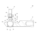
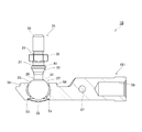
- FIG. 1 is a side view illustrating the appearance of a ball joint according to this embodiment.
- FIG. 2 is a longitudinal sectional side view showing a configuration example of the ball joint according to the present embodiment.
- FIG. 3 is a partially enlarged view of the ball joint according to the present embodiment, a partial view (a) in FIG. 3 is an enlarged view of a portion A in FIG. 2, and a partial view (b) in FIG.
- FIG. 3 is an enlarged view of a portion B in FIG. 2.
- FIG. 4 is an external side view illustrating a state in which a dust cover is attached to the ball joint according to this embodiment.
- FIG. 5 is a vertical cross-sectional side view illustrating a state where a dust cover is attached to the ball joint according to the present embodiment.
- FIG. 6 is a schematic diagram for explaining a method for manufacturing a ball stud according to the present embodiment, and a partial diagram (a) in FIG. 6 is a schematic diagram showing the ball stud before performing the welding process.
- FIG. 6B is a schematic diagram showing the ball stud after the welding process is executed, and
- FIG. 6C is a schematic diagram showing the ball stud after the cutting process is executed.
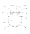
- FIG. 7 is a view for explaining the result of investigating the metal structure of the ball stud manufactured by the ball stud manufacturing method according to the present embodiment.
- FIG. 8 is a longitudinal sectional side view showing a modified example of the ball joint according to the present embodiment.
- FIG. 9 is a diagram illustrating a specific configuration example of an external shape that can be taken by the ball joint according to the present embodiment and the modification.
- FIG. 10 is a diagram illustrating a specific configuration example of an external shape that can be taken by the ball joint according to the present embodiment and the modification.
- FIG. 1 is a side view illustrating the appearance of the ball joint according to the present embodiment
- FIG. 2 is a longitudinal sectional side view illustrating a configuration example of the ball joint according to the present embodiment
- FIG. 3 is a partially enlarged view of the ball joint according to the present embodiment.
- FIG. 3A is an enlarged view of a portion A in FIG. 2, and
- FIG. ) Is an enlarged view of a portion B in FIG.
- FIG. 4 is an external side view illustrating a state in which the dust cover is mounted on the ball joint according to the present embodiment
- FIG. 5 illustrates a state in which the dust cover is mounted on the ball joint according to the present embodiment. It is a longitudinal cross-sectional side view.
- a ball joint 10 includes a ball stud 21 having a spherical ball portion 23 and a shaft portion 25, and a holder 51 that rotatably holds the ball portion 23. And is configured.
- the ball stud 21 is formed by welding a spherical ball portion 23 and an axial shaft portion 25. As shown in a partial diagram (a) in FIGS. 2 and 3, the ball stud 21 has a welded portion 27 in which a ball portion 23 and a shaft portion 25 are welded. That is, the welded portion 27 is composed of a part of the ball part 23 and a part of the shaft part 25.
- the welded portion 27 is formed with a machined surface 29 that is cut, and the machined surface 29 is a curved first corner portion. 31.
- the strength is improved as compared with the case where the ball portion 23 and the shaft portion 25 are welded to form a machining surface in a linear shape. Will be.
- the first corner portion 31 is disposed on the ball portion 23. Since the first corner portion 31 is disposed on the ball portion 23, the formation position of the first corner portion 31 and the formation position of the welding portion 27 are provided so as not to overlap with each other.
- the radius of curvature of the first corner portion 31 is formed larger than the radius of curvature of the second corner portion 41 described later. This is because the first corner formed near the welded portion 27 by concentrating the stress toward the second corner portion 41 formed with a smaller curvature radius than the first corner portion 31 formed with a larger curvature radius. This is because the influence of stress on the portion 31 can be reduced.
- the ball joint 10 according to the present embodiment can prevent stress from being concentrated on the welded portion 27 when the ball joint 10 swings. It can prevent suitably that welding will peel.
- a steel ball for a bearing having a high sphericity is used for the ball portion 23.
- a gap between the ball portion 23 and a resin sliding contact member 53 described later can be reduced, and smooth swinging of the ball joint 10 is realized.
- the shaft portion 25 is formed between the truncated cone-shaped truncated cone portion 33, the flange-shaped flange portion 35, and the truncated cone-shaped portion 33 and the flange portion 35.
- a male screw part 39 in which a male screw is formed on the opposite side of the shaft part 25 to the ball part 23 welding side.
- the truncated cone-shaped portion 33 and the concave portion 37 are connected to each other with a curved second corner portion 41.
- the curvature of the second corner portion 41 is formed to be smaller than the curvature of the first corner portion 31, stress is applied to the second corner portion 41 when viewed with the ball stud 21 as a whole. Configured to concentrate. With such a configuration, the ball joint 10 according to the present embodiment can prevent stress from being concentrated on the welded portion 27 when the ball joint 10 swings. It becomes possible to prevent the welding from peeling off.
- a dust cover 61 (to be described later) can be attached to a recess 37 formed between the truncated cone portion 33 and the flange portion 35.
- the external thread part (not shown) in which the internal thread fitted to the external thread of the external thread part 39 is formed is connected to the external thread part 39.
- the holder 51 has a resin sliding contact member 53 made of resin, a cap portion 55 for enclosing a lubricant, a step portion 56 for attaching a dust cover 61 described later, and a female screw portion 59 in which a female screw is formed. A lubricant is enclosed in the cap portion 55 and a dust cover 61 described later.
- the resin sliding contact member 53 is for preventing the wear of the ball part 23, and the ball part 23 can be rotated via a lubricant.
- an external part such as a rod formed with a male screw that fits into the female screw of the female screw part 59 is connected to the female screw part 59. Therefore, in the ball joint 10 according to the present embodiment, an external part (not shown) in which a female screw that fits the male screw of the male screw portion 39 is formed, and a male screw that fits the female screw of the female screw portion 59 is formed. A function of link-connecting external parts (not shown) such as a rod can be exhibited.
- the ball joint 10 uses the stepped portion 56 formed in the concave portion 37 of the shaft portion 25 of the ball stud 21 and the holder 51, and the ball portion 23. It is possible to attach a dust cover 61 for preventing dust or dust from entering between the holder 51.
- the dust cover 61 has an accordion shape, and even if the ball joint 10 having a large oscillating angle is oscillated by the expansion and contraction of the heel constituting the accordion shape, It is possible to cover a part, and it is possible to prevent dust or dust from entering between the ball part 23 and the holder 51. As described above, the lubricant is sealed in the cap portion 55 and the dust cover 61.
- FIG. 6 is a schematic diagram for explaining the ball stud manufacturing method according to the present embodiment
- FIG. 6A is a schematic diagram showing the ball stud before performing the welding process
- 6 is a schematic diagram showing the ball stud after performing the welding process
- FIG. 6C is a schematic diagram after performing the cutting process. It is the schematic which shows a ball stud.
- the manufacturing method of the ball joint 10 includes a welding process of welding the spherical ball portion 23a and the shaft-shaped shaft portion 25a, and a welding portion 27 where the ball portion 23 and the a-axis portion 25a are welded. And a cutting process for forming the processed surface 29 by performing the cutting process.
- a ball portion 23 a having a high sphericity and a shaft portion 25 a that has a shaft diameter larger than the shaft portion 25 and that is formed before the cutting are welded. (Welding process). Any known welding means can be used as the welding means used in the welding process.
- Projection welding is a type of electrical resistance welding, and the shaft portion 25 can be suitably welded to the ball portion 23a. That is, referring to FIG. 2 and FIG. 6 at the same time, the lower end surface of the shaft portion 25 is pressed against the upper spherical surface of the ball portion 23a exposed from the holder 51 with a predetermined force (partial view in FIG. 6). (Refer to the state of (a)), electrodes (not shown) are brought into contact with the holder 51 and the shaft portion 25, respectively, and a welding current is supplied to the holder 51 and the shaft portion 25.
- the holder 51 is manufactured by casting the ball portion 23a and the resin sliding contact member 53 as a core, and a tip concave spherical surface (not shown) to which the spherical surface of the ball portion 23a is transferred is provided at the ball installation location of the holder 51. Is formed.
- the concave spherical surface of the tip not shown is in contact with the spherical surface of the ball portion 23a without a gap. For this reason, by bringing the electrode into contact with the vicinity of the ball installation location of the holder 51, a welding current can be supplied from the ball installation location to the ball portion 23a, and the ball portion 23a and the shaft portion 25a are electrically connected to each other. It becomes possible to weld.
- the energization resistance between the ball installation location of the holder 51 and the ball portion 23a is smaller than the energization resistance between them. It is. If the energization resistance between the ball installation location of the holder 51 and the ball portion 23a is larger than that between the ball portion 23a and the shaft portion 25a, the ball installation location of the holder 51 and the ball portion 23a This is because the boundary surface generates heat and the ball installation location of the holder 51 is fixed to the ball portion 23a.
- the contact area between the ball installation location of the holder 51 and the ball portion 23a needs to be set larger than the welded portion area between the ball portion 23a and the shaft portion 25a.
- the welded portion area is an area where the tip surface of the shaft portion 25a is welded to the ball portion 23a, and corresponds to a cross-sectional area of the shaft portion 25a. More precisely, it is the surface area of the spherical surface of the ball portion 23a at the site where the shaft portion 25a is welded to the ball portion 23a.
- the ball 51 After the casting of the holder 51 and before the shaft portion 25a is welded to the ball portion 23a, the ball 51 is placed outside the resin sliding contact member 53 due to the shrinkage of the holder 51 that proceeds after casting. Since the ball portion 23a is tightened from the beginning, a large resistance acts on the rotation of the ball portion 23a with respect to the resin sliding contact member 53 as it is. Further, since the concave spherical surface (not shown) formed at the ball installation location of the holder 51 by the casting of the holder 51 is in close contact with the ball portion 23a, the free rotation of the ball portion 23a is also performed at this point. You are in a blocked state.
- the shaft portion 25a is electrically resistance-welded to the ball portion 23a after the holder 51 is cast
- the ball portion 23a is heated around the welded portion of the ball portion 23a and the shaft portion 25a to heat the ball portion 23a.
- the heat is also transmitted to the resin sliding contact member 53 fastening the 23a. Since there is a difference in the coefficient of thermal expansion between the ball portion 23a and the resin sliding contact member 53, and there is also a difference in the contraction speed during cooling, the resin sliding contact member 53 once spread by heating is It is not possible to completely return to the original shape at the contraction stage, and the tightening of the resin sliding contact member 53 to the ball portion 23a can be loosened.
- the ball part 23a itself causes a slight thermal expansion at a lower temperature than normal temperature and pushes the resin sliding contact member 53, but the heat source is a welded part between the ball part 23a and the shaft part 25a.
- the portion 23a has a large expansion amount in the vicinity of the upper portion of the holder 51 where the ball is placed, and the expansion amount is smaller in the vicinity of the lower portion of the holder 51 where the ball is placed away from the heat source than in the vicinity of the upper portion. Become. That is, the amount by which the resin sliding contact member 53 is expanded by the thermal expansion of the ball portion 23a is larger in the vicinity of the upper portion of the holder 51 than the lower portion of the ball setting portion than in the vicinity of the lower portion of the holder 51.
- the ball portion 23a is slightly displaced in the direction in which the ball portion 23a is lifted from the ball installation location of the holder 51.
- the portion 23a is in contact with the concave spherical surface (not shown) at the ball installation location of the holder 51, the contact surface pressure between both is reduced.
- the ball joint 10 when the electric resistance welding of the shaft portion 25a to the ball portion 23a is completed, the tightening force of the resin sliding contact member 53 to the ball portion 23a is reduced, and the ball portion 23a and the holder 51 are further reduced.
- the contact surface pressure with the concave spherical surface (not shown) at the ball installation location is reduced, and the ball stud 21 completed by the welding can be moved lightly with respect to the holder 51.
- the measure which slows cooling is implemented in the center site
- the ball portion 23a and the shaft portion 25a are welded, heat is generated by making the shaft diameter of the shaft portion 25a larger than the shaft diameter of the finished product. It is possible to increase the welding strength of the welded portion 27 where the ball portion 23 and the shaft portion 25 are welded, and to reduce the starting torque for swinging the ball joint 10. .
- a processed surface 29 is formed by cutting the welded portion 27 where the ball portion 23a and the shaft portion 25a are welded (cutting step).
- a partial diagram (b) in FIG. 6 a part of the welded ball portion 23 a and the shaft portion 25 a, that is, the welded portion 27, is shown by a one-dot chain line in the partial diagram (b) in FIG. 6.
- the welded portion 27 is in the state shown in the partial diagram (c) in FIG.
- the shaft portion 25 in which the shaft diameter of the shaft portion 25a is smaller than that at the time of welding is formed by performing the cutting process on the welded portion 27, and the machining is performed.
- a surface 29 is formed, the beads 28 are removed, and a first corner portion 31 is formed in the ball portion 23. That is, the cutting process includes a process of forming the first corner portion 31 with respect to the processed surface 29.
- the shaft diameter of the shaft portion 25a is reduced, the processed surface 29 is formed, the bead 28 is removed, and the first corner portion 31 is formed. Can be done quickly in a series of operations.
- the shaft diameter of the shaft portion 25 of the ball stud 21 can be made smaller, so that the ball joint 10 having a large swing angle is provided. Will be able to.
- the bead 28 may become a starting point at which the welding of the welded portion 27 is peeled off. Therefore, according to the method for manufacturing the ball joint 10 according to this embodiment in which the step of removing the bead 28 is performed, it is possible to suitably prevent the welded portion 27 from being peeled off.
- the ball joint 10 having improved strength is provided by forming the first corner portion 31 on the processed surface 29 formed on the welded portion 27. Can do.
- first corner portion 31 is formed with respect to the ball portion 23, the formation positions of the first corner portion 31 and the welded portion 27 are separated from each other, so that stress can be prevented from being concentrated on the welded portion 27. It is possible to prevent the welding of the ball part 23 and the shaft part 25 from being peeled off.
- the first corner portion 31 formed on the processed surface 29 is formed so that the radius of curvature is larger than the radius of curvature of the second corner portion 41. Therefore, according to the manufacturing method of the ball joint 10 according to the present embodiment, when the ball joint 10 is swung, the ball stud 21 is much larger than the second corner portion 41 having a small radius of curvature when viewed with the ball stud 21 as a whole. Thus, stress concentration on the first corner portion 31 close to the welded portion 27 can be prevented. Therefore, according to the manufacturing method of ball joint 10 concerning this embodiment, it can prevent suitably that stress concentrates on welding part 27, and welding of ball part 23 and axis part 25 will exfoliate. Can be prevented.
- the ball stud 21 in which the ball portion 23 and the shaft portion 25 are welded by the manufacturing method described above is rotatably installed on the holder 51 via the resin sliding contact member 53.
- the method for manufacturing the ball joint according to the present invention is not limited to the method described above, and other conventionally known techniques can be used. It is. That is, the feature point of the manufacturing method of the ball joint 10 according to the present embodiment is characterized in the manufacturing process of the ball stud 21.
- FIG. 7 is a figure for demonstrating the result of having investigated the metal structure of the ball stud manufactured with the manufacturing method of the ball stud which concerns on this embodiment.
- the part indicated by reference numeral C1 in FIG. 7 is a part that is not affected by heat in the shaft portion 25a, and the metal structure thereof shows a medium carbon martensite structure.
- symbol C2 in FIG. 7 is a site
- the parts indicated by reference signs D1 to D4 in FIG. 7 are the parts that have been investigated for the ball part 23a.
- symbol D1 in FIG. 7 is a part of the carburization hardening layer which the ball
- symbol D2 in FIG. 7 is a boundary location of the carburizing quenching layer of the surface layer which the ball
- bowl part 23a is the location which received the heat influence most by the welding process mentioned above,
- the metal structure Shows a mixed structure of high carbon martensite and bainite.
- the metal structure of the ball stud 21 obtained by carrying out the manufacturing method according to the present embodiment is very It was found that the metal structure is advantageous to the above. That is, in the formation part of the bead 28 indicated by the symbol E2 in FIG. 7, a sudden tissue change and a notch-shaped part called the bead 28 are formed. Therefore, there is a possibility of fracture when stress concentration occurs in the part. . However, in the manufacturing method according to the present embodiment, in the central part of the welded joint between the ball portion 23a and the shaft portion 25a indicated by reference numeral E1 in FIG. Pearlite is deposited, and the strength of this part is to be reduced compared to other parts.
- the stress is dispersed by reducing the strength of the central part of the weld joint indicated by reference numeral E1, and the stress concentration on the formation part of the bead 28 indicated by reference numeral E2 can be relaxed.
- the fracture strength of the welded portion at 21 is increased, and it is possible to suitably prevent the occurrence of abnormality during welding. Such an effect contributes to effectively reducing the production defect occurrence rate at the time of producing the ball stud 21 and also exhibits an effect of reducing the production cost.
- the above effect is effective even after the ball stud 21 is completed by performing the cutting process.
- the metal structure inside the welded portion 27 in the ball stud 21 is denoted by reference numeral E1 in FIG.
- E1 The metal structure inside the welded portion 27 in the ball stud 21
- the appearance of fine pearlite precipitated at the crystal grain boundaries combined with the effect obtained from the outer shape of the first corner portion 31 described above, improves the breaking strength of the ball stud 21 according to the present embodiment. It contributes to. Therefore, according to the manufacturing method of the ball joint 10 according to the present embodiment, it is possible to prevent stress from being concentrated on the welded portion 27 from a suitable action from both the surface of the metal structure and the surface of the shape. 23 and the shaft portion 25 can be prevented from being peeled off.
- FIG. 8 is a longitudinal sectional side view showing a modified example of the ball joint according to the present embodiment.
- symbol is attached
- the holder 151 includes a resin sliding contact member 53 made of resin, a cap portion 55 that encloses a lubricant, a step portion 56, and a pin 57 that is outsert-molded in the holder 151. And an internal thread portion 59 in which an internal thread is formed.
- the pin 151 is outsert-molded on the holder 151 according to the modified example, and an external part (not shown) such as a rotary bearing can be attached.
- an external part such as a rotary bearing
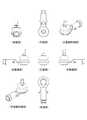
- FIG. 9 and FIG. 10 are shown as a configuration example specifically illustrating the ball joint 10 according to the present embodiment and the modification described above.
- FIG. 9 and FIG. 10 are diagrams illustrating a specific configuration example of the external shape that can be taken by the ball joint according to the present embodiment and the modification.
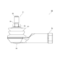
- FIG. 9 shows the ball joint without the dust cover attached
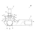
- FIG. 10 shows the ball joint with the dust cover attached.
Landscapes
- Engineering & Computer Science (AREA)
- General Engineering & Computer Science (AREA)
- Mechanical Engineering (AREA)
- Pivots And Pivotal Connections (AREA)
Abstract
このボールジョイント10は、球形状のボール部23と軸状の軸部25とを有するボールスタッド21と、ボール部23を回動自在に保持するホルダ51と、を備えるものであって、ボール部23と軸部25とが溶接された溶接部27に、切削加工が施された加工面29を有し、加工面29は、曲線形状の第一コーナー部31を有するものである。また、このボールジョイント10の製造方法は、ボール部23aと軸部25aとを溶接する溶接工程と、ボール部23aと軸部25aが溶接された溶接部27に切削加工を施すことで加工面29を形成する切削加工工程と、を含み、切削加工工程は、加工面29に対して曲線形状の第一コーナー部31を形成する工程を含む処理を実行するものである。これらによって、揺動角度が大きいボールジョイントを得ることができる。
Description
本発明は、ボールジョイントおよびボールジョイントの製造方法に関するものである。
従来から、球形状のボール部と軸状の軸部とを有するボールスタッドと、ボール部を回動自在に保持するホルダと、を有して構成されるボールジョイントが知られている。例えば、下記の特許文献1には、球状のボールヘッド部の形状に対応するボールヘッド成形用モールドに、ねじ軸状部材の雄ねじ部を挿入して溶解された樹脂を注入することにより、ボールヘッド部が形成されるととともに、当該ボールヘッド部とねじ軸状部材とが連結されるボールジョイントと、その製造方法が開示されている。
しかしながら、上掲の特許文献1に記載のボールジョイントでは、ボールヘッド部とねじ軸状部材との連結部分の軸径は、ねじ軸状部材の軸径よりも大きくなってしまい、ボールジョイントの揺動角度を大きくすることができないという課題があった。したがって、ボールスタッドの軸部の軸径がより小さく形成されて揺動角度が大きくなるボールジョイントの実現が望まれていた。
そこで、本発明は上述した課題に鑑みて成されたものであり、その目的は、揺動角度が大きいボールジョイントおよびボールジョイントの製造方法を提供することにある。
本発明に係るボールジョイントは、球形状のボール部と軸状の軸部とを有するボールスタッドと、前記ボール部を回動自在に保持するホルダと、を備えるボールジョイントであって、前記ボール部と前記軸部とが溶接された溶接部に、切削加工が施された加工面を有し、前記加工面は、曲線形状の第一コーナー部を有することを特徴とするものである。
また、本発明に係るボールジョイントの製造方法は、球形状のボール部と軸状の軸部とを有するボールスタッドと、前記ボール部を回動自在に保持するホルダと、を備えるボールジョイントの製造方法であって、前記ボール部と前記軸部とを溶接する溶接工程と、前記ボール部と前記軸部が溶接された溶接部に切削加工を施すことで加工面を形成する切削加工工程と、を含み、前記切削加工工程は、前記加工面に対して曲線形状の第一コーナー部を形成する工程を含む処理を実行することを特徴とするものである。
本発明によれば、揺動角度が大きいボールジョイントと、そのボールジョイントを製造するための製造方法を提供することができる。
以下、本発明を実施するための好適な実施形態について、図面を用いて説明する。なお、以下の実施形態は、各請求項に係る発明を限定するものではなく、また、実施形態の中で説明されている特徴の組み合わせの全てが発明の解決手段に必須であるとは限らない。
まず、本実施形態に係るボールジョイントの構成例について、図1ないし図5を用いて説明する。ここで、図1は、本実施形態に係るボールジョイントの外観を例示する側面図であり、図2は、本実施形態に係るボールジョイントの構成例を示す縦断面側面図である。また、図3は、本実施形態に係るボールジョイントの部分拡大図であり、図3中の分図(a)は、図2中のA部拡大図であり、図3中の分図(b)は、図2中のB部拡大図である。さらに、図4は、本実施形態に係るボールジョイントにダストカバーを装着した状態を例示する外観側面図であり、図5は、本実施形態に係るボールジョイントにダストカバーを装着した状態を例示する縦断面側面図である。
図1に示すように、本実施形態に係るボールジョイント10は、球形状のボール部23と軸状の軸部25とを有するボールスタッド21と、ボール部23を回動自在に保持するホルダ51と、を有して構成される。
ボールスタッド21は、球形状のボール部23と軸状の軸部25とを溶接することより形成される。図2および図3中の分図(a)に示すように、ボールスタッド21は、ボール部23と軸部25とが溶接された溶接部27を有する。すなわち、溶接部27は、ボール部23の一部と軸部25の一部とから構成されている。
図1、図2および図3中の分図(a)に示すように、溶接部27には切削加工が施された加工面29が形成され、当該加工面29は曲線形状の第一コーナー部31を有している。溶接部27に形成された加工面29に第一コーナー部31が設置されることにより、ボール部23と軸部25とが溶接され直線形状で加工面が形成されている場合よりも強度が向上することとなる。また、図1、図2および図3中の分図(a)に示すように、第一コーナー部31は、ボール部23に配置される。第一コーナー部31がボール部23に配置されることにより、第一コーナー部31の形成位置と溶接部27の形成位置とが重畳せずにずれて設けられることになるので、溶接部27に応力が集中することを防ぐことができ、ボール部23と軸部25との溶接が剥離してしまうことを防ぐことができるようになっている。さらに、第一コーナー部31の曲率半径は、後述する第二コーナー部41の曲率半径よりも大きく形成される。なぜなら、曲率半径が大きく形成された第一コーナー部31よりも、曲率半径の小さく形成された第二コーナー部41の方に応力を集中させることで、溶接部27近くに形成された第一コーナー部31への応力の影響を軽減することができるからである。このような構成により、本実施形態に係るボールジョイント10は、ボールジョイント10が揺動したときに、溶接部27に応力が集中することを防ぐことができ、ボール部23と軸部25との溶接が剥離してしまうことを好適に防止することができるようになっている。
なお、ボール部23には、真球度が高い軸受用鋼球が用いられる。ボール部23として真球度が高い軸受用鋼球を用いることにより、ボール部23と後述する樹脂摺接部材53との隙間を小さくすることができ、ボールジョイント10の滑らかな揺動が実現されることとなる。
また、図1および図2に示すように、軸部25は、円錐台形状の円錐台形状部33と、鍔状のフランジ部35と、円錐台形状部33とフランジ部35との間に形成される凹部37と、軸部25のボール部23溶接側とは反対側に雄ねじが形成される雄ねじ部39と、を有して構成される。
図3中の分図(b)に示すように、円錐台形状部33と凹部37とは、曲線形状の第二コーナー部41を有して接続される。上述したように、第二コーナー部41の曲率は、第一コーナー部31の曲率よりも小さく形成されているので、ボールスタッド21全体で見たときに、第二コーナー部41に対して応力が集中するように構成されている。このような構成により、本実施形態に係るボールジョイント10は、ボールジョイント10が揺動したときに、溶接部27に応力が集中することを防ぐことができ、ボール部23と軸部25との溶接が剥離してしまうことを防ぐことができるようになる。
円錐台形状部33とフランジ部35との間に形成される凹部37には、後述するダストカバー61を取り付けられるようになっている。
雄ねじ部39には、当該雄ねじ部39の雄ねじに嵌合する雌ねじが形成される外部部品(不図示)が接続される。
ホルダ51は、樹脂製の樹脂摺接部材53と、潤滑剤を封入するキャップ部55と、後述するダストカバー61を取り付けるための段差部56と、雌ねじが形成される雌ねじ部59と、を有して構成され、キャップ部55および後述するダストカバー61内には潤滑剤が封入される。
樹脂摺接部材53は、ボール部23の摩滅を防ぐためのものであり、潤滑剤を介してボール部23を回動可能としている。
雌ねじ部59には、例えば、雌ねじ部59の雌ねじに嵌合する雄ねじが形成されたロッドなどの外部部品(不図示)が接続される。したがって、本実施形態に係るボールジョイント10は、上述した雄ねじ部39の雄ねじに嵌合する雌ねじが形成される外部部品(不図示)と、雌ねじ部59の雌ねじに嵌合する雄ねじが形成されたロッドなどの外部部品(不図示)とを、リンク接続する機能を発揮できる。
図4および図5に示すように、本実施形態に係るボールジョイント10には、ボールスタッド21の軸部25の凹部37およびホルダ51に形成される段差部56を利用して、ボール部23とホルダ51との間に埃や塵芥などが侵入することを防止するためのダストカバー61を取り付けることが可能となっている。
本実施形態に係るダストカバー61は、蛇腹形状となっており、蛇腹形状を構成する襞が伸縮することにより、揺動角度が大きいボールジョイント10を揺動させてもボール部23とホルダ51の一部とを覆うことができ、ボール部23とホルダ51の間に埃や塵芥などが侵入することを防ぐことができるようになっている。そして、上述したように、キャップ部55およびダストカバー61内には、潤滑剤が封入される。
以上、本実施形態に係るボールジョイント10の構成例について、説明した。次に、本実施形態に係るボールジョイント10の製造方法について、図2および図6を用いて説明する。ここで、図6は、本実施形態に係るボールスタッドの製造方法を説明するための概略図であり、図6中の分図(a)は、溶接工程を実行する前のボールスタッドを示す概略図であり、図6中の分図(b)は、溶接工程を実行した後のボールスタッドを示す概略図であり、図6中の分図(c)は、切削加工工程を実行した後のボールスタッドを示す概略図である。
本実施形態に係るボールジョイント10の製造方法は、球形状のボール部23aと軸状の軸部25aとを溶接する溶接工程と、ボール部23とa軸部25aが溶接された溶接部27に切削加工を施すことで加工面29を形成する切削加工工程と、を含む。
まず、図6中の分図(a)に示すように、真球度が高いボール部23aと、軸部25よりも軸径が大きく形成された切削加工前の軸部25aと、を溶接する(溶接工程)。当該溶接工程で用いられる溶接手段については、公知のあらゆる溶接手段を用いることが可能である。
この溶接工程で用いられる溶接手段の具体例としては、例えば、プロジェクション溶接を用いることができる。プロジェクション溶接は、電気抵抗溶接の一種であり、ボール部23aに対して軸部25を好適に溶接することができる。すなわち、図2および図6を同時に参照して説明すると、ホルダ51から露出したボール部23aの球面上側に対して軸部25の下端面を所定の力で圧接させる一方(図6中の分図(a)の状態参照)、ホルダ51および軸部25の夫々に対して不図示の電極を当接させ、これらホルダ51および軸部25に溶接電流を通電する。
ホルダ51は、ボール部23aおよび樹脂摺接部材53を中子として鋳造して製造されており、ホルダ51のボール設置箇所にはボール部23aの球面が転写された先端凹球面(不図示)が形成されている。かかる不図示の先端凹球面は、ボール部23aの球面に隙間なく接触している。このため、ホルダ51のボール設置箇所近傍に電極を当接させることで、当該ボール設置箇所からボール部23aに対して溶接電流を通電することができ、ボール部23aと軸部25aとを電気抵抗溶接することが可能となる。
そして、上記のようにして電気抵抗溶接が終了すると、図6中の分図(b)に示すように、軸部25aの先端面がボール部23aに対して溶接され、ボール部23aが樹脂摺接部材53を介してホルダ51の本体部に保持された状態が完成する。
なお、ボール部23aと軸部25aとを電気抵抗溶接するためには、これら両者の間の通電抵抗に比べてホルダ51のボール設置箇所とボール部23aとの間の通電抵抗が小さいことが必要である。仮に、ホルダ51のボール設置箇所とボール部23aとの間の通電抵抗がボール部23aと軸部25aとの間のそれよりも大きい場合には、ホルダ51のボール設置箇所とボール部23aとの境界面が発熱し、ホルダ51のボール設置箇所がボール部23aに対して固着してしまうからである。このため、ホルダ51のボール設置箇所とボール部23aとの接触面積は、ボール部23aと軸部25aとの溶接部面積よりも大きく設定される必要がある。ここで溶接部面積とは、軸部25aの先端面がボール部23aと溶接された面積であり、軸部25aの断面積に相当している。より厳密には、軸部25aがボール部23aと溶接される部位における当該ボール部23aの球面の表面積である。
ホルダ51の鋳造後であって軸部25aをボール部23aに対して溶接する以前の段階では、鋳造後に進行するホルダ51の収縮により、当該ホルダ51のボール設置箇所が樹脂摺接部材53の外側からボール部23aを締め付ける状態となるので、そのままでは樹脂摺接部材53に対するボール部23aの回転には大きな抵抗が作用する。また、ホルダ51の鋳造によってホルダ51のボール設置箇所に形成された先端凹球面(不図示)はボール部23aに緊密に接触していることから、この点においてもボール部23aの自由な回転は妨げられた状態にある。
しかし、ホルダ51の鋳造後に、ボール部23aに対して軸部25aを電気抵抗溶接すると、ボール部23aと軸部25aの溶接部分の周辺が発熱源となってボール部23aが加熱され、ボール部23aを締め付けている樹脂摺接部材53にもその熱が伝達される。ボール部23aと樹脂摺接部材53は熱膨張率に差が存在し、且つ、冷却時の収縮速度にも差が存在することから、加熱によって一旦広げられた樹脂摺接部材53が冷却時の収縮段階で元の形状にまで完全には戻りきらず、ボール部23aに対する樹脂摺接部材53の締め付けを緩めることが可能となる。
このとき、ボール部23aそれ自身は常温下よりも僅かに熱膨張を生じて樹脂摺接部材53を押し拡げることになるが、発熱源はボール部23aと軸部25aとの溶接部分なので、ボール部23aは、ホルダ51のボール設置箇所の上方部分の近傍で膨張量が大きくなり、発熱源から離れたホルダ51のボール設置箇所の下方部分の近傍では上方部分の近傍よりもその膨張量が小さくなる。すなわち、樹脂摺接部材53がボール部23aの熱膨張によって押し拡げられる量は、ホルダ51のボール設置箇所の下方部分の近傍よりもホルダ51のボール設置箇所の上方部分の近傍で大きくなる。その結果、ボール部23aと軸部25aの溶接が完了してボールが冷めた状態では、ボール部23aがホルダ51のボール設置箇所から浮き上がる方向に関して当該ボール部23aが微小変位することになり、ボール部23aはホルダ51のボール設置箇所の先端凹球面(不図示)と接触はしているものの、両者の間の接触面圧は軽減される。
すなわち、本実施形態に係るボールジョイント10では、ボール部23aに対する軸部25aの電気抵抗溶接が完了すると、ボール部23aに対する樹脂摺接部材53の締め付け力が軽減され、更にボール部23aとホルダ51のボール設置箇所の先端凹球面(不図示)との接触面圧が軽減され、当該溶接によって完成したボールスタッド21をホルダ51に対して軽く動かすことが可能となる。
なお、本実施形態で実施される溶接工程では、ボール部23aと軸部25aとの溶接接合の中央部位において、冷却を緩慢にする措置が実施されている。その理由については、後述する金属組織に関する調査結果の説明の際に詳述する。
また、本実施形態に係るボールジョイント10の製造方法は、ボール部23aと軸部25aとを溶接する際に、軸部25aの軸径を完成品の軸径よりも大きくすることで、発熱を増やすことができ、ボール部23と軸部25とが溶接された溶接部27の溶接強度を向上させることができるとともに、ボールジョイント10を揺動する起動トルクを下げることができるようになっている。
ところで、ボール部23aおよび軸部25aに対して上述した溶接工程が実行されると、図6中の分図(b)に示すように、ボール部23aおよび軸部25aの一部が溶融してビード28が形成されることとなる。
そこで次に、ボール部23aと軸部25aとが溶接された溶接部27に切削加工を施すことで加工面29を形成する(切削加工工程)。図6中の分図(b)に示すように、溶接されたボール部23aおよび軸部25aの一部、すなわち溶接部27に対して、図6中の分図(b)の一点鎖線にて示す加工面29の部分まで切削加工を施すことで、溶接部27は、図6中の分図(c)に示す状態となる。本実施形態に係るボールジョイント10の製造方法では、溶接部27に対して切削加工工程を実施することによって、軸部25aの軸径が溶接時よりも小さくなった軸部25が形成され、加工面29が形成され、ビード28が除去され、さらに、ボール部23に第一コーナー部31が形成される。すなわち、切削加工工程は、加工面29に対して第一コーナー部31を形成する工程を含んでいる。
すなわち、本実施形態に係るボールジョイント10の製造方法は、軸部25aの軸径を小さくすること、加工面29を形成すること、ビード28を除去すること、および第一コーナー部31を形成すること、を一連の作業で素早く行うことができるようになっているのである。
以上説明した本実施形態に係るボールジョイント10の製造方法によれば、ボールスタッド21の軸部25の軸径をより小さく形成することができるので、揺動角度が大きいボールジョイント10を提供することができるようになる。また、ビード28は、溶接部27の溶接が剥離する起点となってしまう場合がある。したがって、このビード28を除去する工程を実行する本実施形態に係るボールジョイント10の製造方法によれば、溶接部27の溶接が剥離することを好適に防止することができる。さらに、本実施形態に係るボールジョイント10の製造方法によれば、溶接部27に形成された加工面29に第一コーナー部31を形成することにより、強度が向上したボールジョイント10を提供することができる。また、第一コーナー部31がボール部23に対して形成されることにより、第一コーナー部31と溶接部27との形成位置が離れるので、溶接部27に応力が集中することを防ぐことができ、ボール部23と軸部25との溶接が剥離してしまうことを防ぐことができるようになっている。
ここで、加工面29に形成される第一コーナー部31は、その曲率半径が第二コーナー部41の曲率半径よりも大きくなるように形成されている。したがって、本実施形態に係るボールジョイント10の製造方法によれば、ボールジョイント10が揺動したときに、ボールスタッド21全体で見たときに、曲率半径の小さい第二コーナー部41に対して多くの応力が加わることとなり、溶接部27に近い第一コーナー部31への応力集中を防ぐことができる。よって、本実施形態に係るボールジョイント10の製造方法によれば、溶接部27に応力が集中することを好適に防ぐことができ、ボール部23と軸部25との溶接が剥離してしまうことを防ぐことができるようになっている。
上述した製造方法により、ボール部23と軸部25とが溶接されたボールスタッド21は、樹脂摺接部材53を介してホルダ51に回動可能に設置される。なお、ボールスタッド21とホルダ51との組立方法については上述した通りであるが、本発明に係るボールジョイントの製造方法は上述したものには限られず、他の従来公知の技術を用いることが可能である。すなわち、本実施形態に係るボールジョイント10の製造方法の特徴点は、ボールスタッド21の製造工程に特徴を有するものである。
以上、本実施形態に係るボールジョイント10の製造方法について、説明した。次に、図7を用いることで、本実施形態に係るボールスタッドの製造方法にて製造されたボールスタッドの金属組織を調査した結果を説明する。ここで、図7は、本実施形態に係るボールスタッドの製造方法にて製造されたボールスタッドの金属組織を調査した結果を説明するための図である。
発明者らが上述した製造方法にて製造されたボールスタッド21について、その金属組織を調査したところ、様々な知見を得ることができた。この調査は、ボールスタッド21の各部位を選定した上で各部位を切り出し、樹脂に埋め込み、観察面を鏡面仕上げして薬品にて腐食し、顕微鏡観察することで行われた。
まず、図7中の符号C1で示す部位は、軸部25aにおいて溶接による熱影響を受けていない部位であり、その金属組織は、中炭素マルテンサイト組織を示すものであった。また、図7中の符号C2で示す部位は、軸部25aにおいて溶接による熱影響を受けている部位であり、その金属組織は、ベイナイト組織を示すものであった。
一方、図7中の符号D1~D4で示す部位は、ボール部23aに関する調査を行った部位である。図7中の符号D1で示す部位は、ボール部23aが元々有する浸炭焼入れ層の箇所であり、その金属組織は、高炭素マルテンサイト組織を示すものであった。また、図7中の符号D2で示す部位は、ボール部23aが元々有する表層の浸炭焼入れ層と内部との境界箇所であり、その金属組織は、マルテンサイトとトルースタイトが混在した組織を示すものであった。また、図7中の符号D3で示す部位は、ボール部23aに対して元々実施された浸炭焼入れの影響が及んでいない内部箇所であり、その金属組織は、低炭素マルテンサイトとフェライト・パーライトが混在した組織を示すものであった。また、図7中の符号D4で示す部位は、ボール部23aと軸部25aとの溶接箇所であって、上述した溶接工程によってボール部23aが最も熱影響を受けた箇所であり、その金属組織は、高炭素マルテンサイトとベイナイトが混在した組織を示すものであった。
さらに、発明者らは、ボール部23aと軸部25aとの溶接箇所をより詳細に調査するために、図7中の符号E1およびE2で示す箇所の金属組織の調査を行った。すなわち、図7中の符号E1で示す箇所は、ボール部23aと軸部25aとの溶接接合の中央部位であり、図7中の符号E2で示す箇所は、溶接工程の際にボール部23aおよび軸部25aの一部が溶融して形成されたビード28の形成部位である。そして、図7中の符号E1で示す箇所では、軸部25aの側で金属組織の結晶粒界に微細なパーライトが析出していることが確認できた。一方、図7中の符号E2で示す箇所では、ボール部23aの側にマルテンサイト組織が観察され、軸部25aの側にベイナイト組織が観察された。
以上説明した金属組織観察の結果から言えることとして、まず、本実施形態に係る製造方法を実施することで得られたボールスタッド21の金属組織は、熱影響を受ける溶接工程の実施の際に非常に有利な金属組織であることが分かった。すなわち、図7中の符号E2で示すビード28の形成部位では、急激な組織変化とビード28という切り欠き形状部位が形成されることから、当該箇所に応力集中が起きると破断の可能性がある。しかしながら、本実施形態に係る製造方法では、図7中の符号E1で示すボール部23aと軸部25aとの溶接接合の中央部位において、冷却を緩慢にすることで金属組織の結晶粒界に微細なパーライトを析出させており、この部位の強度を他の部位に比べて低下させることとなっている。つまり、符号E1で示す溶接接合の中央部位の強度を低下させることで応力が分散し、符号E2で示すビード28の形成部位に対する応力集中を緩和することができており、その結果として、ボールスタッド21における溶接部の破断強さが増加し、溶接時の異常発生を好適に防止することが可能となっている。かかる効果は、ボールスタッド21製造時の製造不良発生率を効果的に低減することに寄与しており、製造コストの低減効果をも発揮するものである。
また、上記効果は、切削加工工程を実施してボールスタッド21が完成した後にも効果的に作用するものであり、ボールスタッド21における溶接部27の内部の金属組織が図7中の符号E1で示すように結晶粒界に微細なパーライトが析出する様相を呈することで、上述した第一コーナー部31の外形形状から得られる効果とも相まって、本実施形態に係るボールスタッド21の破断強さの向上に寄与している。したがって、本実施形態に係るボールジョイント10の製造方法によれば、金属組織の面と形状の面の両方からの好適な作用から溶接部27に応力が集中することを防ぐことができ、ボール部23と軸部25との溶接が剥離してしまうことを防ぐことができるようになっている。
次に、本実施形態に係るボールジョイント10の変形例について、図8を用いて説明する。ここで、図8は、本実施形態に係るボールジョイントの変形例を示す縦断面側面図である。なお、上述した実施形態と同一又は類似する構成については、同一符号を付して、説明を省略する。
図8に示すように、変形例に係るホルダ151は、樹脂製の樹脂摺接部材53と、潤滑剤を封入するキャップ部55と、段差部56と、ホルダ151にアウトサート成形されるピン57と、雌ねじが形成される雌ねじ部59と、を有して構成される。
変形例に係るホルダ151には、ピン57がアウトサート成形されており、例えば回転ベアリングなどの外部部品(不図示)を取り付けることができるようになっている。このピン57を利用することで、変形例に係るボールジョイント10の使用範囲のバリエーションが拡大することとなる。
以上、本発明の好適な実施形態について説明した。なお、上述した本実施形態および変形例に係るボールジョイント10を具体的に例示する構成例として、図9および図10を示す。ここで、図9および図10は、本実施形態および変形例に係るボールジョイントが取り得る外観形状の具体的な構成例を示す図である。なお、図9には、ダストカバーを装着していない状態のボールジョイントが示されており、図10には、ダストカバーを装着した状態のボールジョイントが示されている。
以上、本発明の好適な実施形態について説明したが、本発明の技術的範囲は上記実施形態に記載の範囲には限定されない。上記実施形態には、多様な変更又は改良を加えることが可能である。その様な変更又は改良を加えた形態も本発明の技術的範囲に含まれ得ることが、請求の範囲の記載から明らかである。
10 ボールジョイント、21 ボールスタッド、23,23a ボール部、25,25a 軸部、27 溶接部、28 ビード、29 加工面、31 第一コーナー部、33 円錐台形状部、35 フランジ部、37 凹部、39 雄ねじ部、41 第二コーナー部、51,151 ホルダ、53 樹脂摺接部材、55 キャップ部、56 段差部、57 ピン、59 雌ねじ部、61 ダストカバー。
Claims (6)
- 球形状のボール部と軸状の軸部とを有するボールスタッドと、
前記ボール部を回動自在に保持するホルダと、
を備えるボールジョイントであって、
前記ボール部と前記軸部とが溶接された溶接部に、切削加工が施された加工面を有し、
前記加工面は、曲線形状の第一コーナー部を有することを特徴とするボールジョイント。 - 請求項1に記載のボールジョイントにおいて、
前記第一コーナー部は、少なくとも一部が前記ボール部に配置されることを特徴とするボールジョイント。 - 請求項1又は2に記載のボールジョイントにおいて、
前記ボールスタッドの前記軸部は、円錐台形状の円錐台形状部と、鍔状のフランジ部と、前記円錐台形状部と前記フランジ部との間に形成される凹部と、を備え、
前記円錐台形状部と前記凹部とは、曲線形状の第二コーナー部を有して接続され、さらに、
前記第一コーナー部の曲率半径が、前記第二コーナー部の曲率半径よりも大きく形成されることを特徴とするボールジョイント。 - 請求項1~3のいずれか1項に記載のボールジョイントにおいて、
前記ボール部と前記軸部とが溶接された前記溶接部の中央部位の金属組織が、結晶粒界に微細なパーライトが析出した様相を呈するものであることを特徴とするボールジョイント。 - 球形状のボール部と軸状の軸部とを有するボールスタッドと、前記ボール部を回動自在に保持するホルダと、を備えるボールジョイントの製造方法において、
前記ボール部と前記軸部とを溶接する溶接工程と、
前記ボール部と前記軸部が溶接された溶接部に切削加工を施すことで加工面を形成する切削加工工程と、
を含み、
前記切削加工工程は、前記加工面に対して曲線形状の第一コーナー部を形成する工程を含む処理を実行することを特徴とするボールジョイントの製造方法。 - 請求項5に記載のボールジョイントの製造方法において、
前記溶接工程は、前記ボール部と前記軸部とが溶接された前記溶接部の中央部位において、溶接後の冷却を緩慢にすることで金属組織の結晶粒界に微細なパーライトを析出させる処理を実行することを特徴とするボールジョイントの製造方法。
Priority Applications (3)
| Application Number | Priority Date | Filing Date | Title |
|---|---|---|---|
| US15/571,916 US10495139B2 (en) | 2015-05-11 | 2016-03-01 | Ball joint and method for manufacturing ball joint |
| DE112016002155.0T DE112016002155B4 (de) | 2015-05-11 | 2016-03-01 | Kugelgelenk und Verfahren zur Herstellung eines Kugelgelenks |
| CN201680025023.5A CN107532641B (zh) | 2015-05-11 | 2016-03-01 | 球窝接头以及球窝接头的制造方法 |
Applications Claiming Priority (2)
| Application Number | Priority Date | Filing Date | Title |
|---|---|---|---|
| JP2015096541A JP6016979B1 (ja) | 2015-05-11 | 2015-05-11 | ボールジョイントおよびボールジョイントの製造方法 |
| JP2015-096541 | 2015-05-11 |
Publications (1)
| Publication Number | Publication Date |
|---|---|
| WO2016181590A1 true WO2016181590A1 (ja) | 2016-11-17 |
Family
ID=57197584
Family Applications (1)
| Application Number | Title | Priority Date | Filing Date |
|---|---|---|---|
| PCT/JP2016/001101 Ceased WO2016181590A1 (ja) | 2015-05-11 | 2016-03-01 | ボールジョイントおよびボールジョイントの製造方法 |
Country Status (6)
| Country | Link |
|---|---|
| US (1) | US10495139B2 (ja) |
| JP (1) | JP6016979B1 (ja) |
| CN (1) | CN107532641B (ja) |
| DE (1) | DE112016002155B4 (ja) |
| TW (1) | TWI616598B (ja) |
| WO (1) | WO2016181590A1 (ja) |
Families Citing this family (6)
| Publication number | Priority date | Publication date | Assignee | Title |
|---|---|---|---|---|
| USD839795S1 (en) * | 2016-12-02 | 2019-02-05 | Stemco Products, Inc. | Tie rod end |
| US11067116B2 (en) * | 2018-09-10 | 2021-07-20 | Federal-Mogul Motorparts Llc | Low torque ball socket assembly |
| EP4012206B1 (en) | 2019-09-02 | 2024-11-06 | Yamaha Hatsudoki Kabushiki Kaisha | Leaning vehicle |
| CN110788273A (zh) * | 2019-09-26 | 2020-02-14 | 浙江瑞强汽车部件有限公司 | 一种汽车发动机装饰螺栓及其冷镦成型工艺 |
| WO2023113054A1 (ko) * | 2021-12-13 | 2023-06-22 | 주식회사 일진 | 볼스터드 및 이의 제조방법 |
| CA3218399A1 (en) * | 2022-10-27 | 2024-04-27 | National Research Council Of Canada | Joining of high wear resistant and base materials |
Citations (5)
| Publication number | Priority date | Publication date | Assignee | Title |
|---|---|---|---|---|
| US3831245A (en) * | 1973-03-01 | 1974-08-27 | Columbus Auto Parts | Method of producing ball joints |
| JPS5427658A (en) * | 1977-08-03 | 1979-03-01 | Musashi Seimitsu Kogyo Kk | Method for manufacturing ball stud for ball joint |
| JPS61168322U (ja) * | 1985-04-10 | 1986-10-18 | ||
| US5951195A (en) * | 1997-08-16 | 1999-09-14 | Volkswagen Ag | Method for producing a ball pivot arrangement and ball pivot arrangement for a ball joint |
| JP2004278666A (ja) * | 2003-03-14 | 2004-10-07 | Nhk Spring Co Ltd | ボールスタッド及びそのボールスタッドを使用したボールジョイント並びにボールスタッドの製造方法 |
Family Cites Families (27)
| Publication number | Priority date | Publication date | Assignee | Title |
|---|---|---|---|---|
| US3965554A (en) * | 1973-03-01 | 1976-06-29 | The Columbus Auto Parts Company | Method of producing ball joints |
| US4979844A (en) * | 1987-08-11 | 1990-12-25 | Hiroshi Teramachi | Ball joint and manufacturing method of the same |
| DE4032541A1 (de) * | 1990-10-13 | 1992-04-16 | Trw Ehrenreich Gmbh | Kugelgelenk |
| US5876149A (en) * | 1995-06-29 | 1999-03-02 | Trw Fahrwerksysteme Gmbh & Co. Kg | Ball joint |
| WO1998055774A1 (en) * | 1996-01-11 | 1998-12-10 | Thk Co., Ltd. | Method for manufacturing a ball joint |
| JP2000081025A (ja) | 1998-09-07 | 2000-03-21 | Bridgestone Corp | ボールジョイントおよびその製造方法 |
| KR100625561B1 (ko) * | 1998-10-30 | 2006-09-20 | 티에치케이 가부시끼가이샤 | 볼조인트를 구비한 커넥팅로드 및 그 제조방법 |
| BR0003450B1 (pt) * | 2000-07-28 | 2009-01-13 | vedador para articulaÇço esfÉrica. | |
| DE602004011371T2 (de) | 2004-11-25 | 2009-01-08 | Industria Auxiliar Alavesa, S.A. (Inauxa, S.A.), Amurrio | Kugelgelenk |
| DE102005034210B4 (de) * | 2005-07-19 | 2008-04-10 | Zf Friedrichshafen Ag | Verfahren zur Herstellung eines Kugelgelenks und danach hergestelltes Gelenk |
| DE102007011360B4 (de) * | 2007-03-07 | 2026-03-19 | Zf Friedrichshafen Ag | Kugelzapfen |
| US7585572B2 (en) * | 2007-05-18 | 2009-09-08 | Kyoritsu Seiki Co., Ltd. | Ball stud |
| US9476447B2 (en) * | 2008-05-21 | 2016-10-25 | Federal-Mogul Powertrain, Inc. | Ball joint assembly and method of making |
| DE102008063813A1 (de) * | 2008-12-19 | 2010-07-01 | Zf Friedrichshafen Ag | Kugelgelenk und Verfahren zu seiner Herstellung |
| DE102009042714A1 (de) * | 2009-09-23 | 2011-03-24 | Acument Gmbh & Co. Ohg | Kugelbolzen |
| JP5222885B2 (ja) * | 2010-04-21 | 2013-06-26 | 日本発條株式会社 | スタッドボール、ダストカバー、および、スタビリンク |
| JP5307083B2 (ja) * | 2010-07-06 | 2013-10-02 | 日本発條株式会社 | ボールジョイント製造方法 |
| JP5189145B2 (ja) * | 2010-08-23 | 2013-04-24 | 日本発條株式会社 | スタビリンクおよびその製造方法 |
| JP5718620B2 (ja) * | 2010-11-19 | 2015-05-13 | 日本発條株式会社 | スタビリンクの製造方法 |
| JP5826508B2 (ja) * | 2011-04-14 | 2015-12-02 | 日本発條株式会社 | スタビリンクの製造方法 |
| JP5709665B2 (ja) * | 2011-06-20 | 2015-04-30 | 日本発條株式会社 | スタビリンクおよびその製造方法 |
| CN104024665B (zh) * | 2011-12-28 | 2017-08-08 | Thk株式会社 | 球窝接头及其制造方法 |
| JP5476402B2 (ja) * | 2012-02-16 | 2014-04-23 | 日本発條株式会社 | スタビリンクおよびその製造方法 |
| JP6150348B2 (ja) * | 2012-03-14 | 2017-06-21 | 株式会社ソミック石川 | ボールジョイント用ベアリングシートおよびボールジョイント |
| JP6043093B2 (ja) * | 2012-05-25 | 2016-12-14 | 株式会社ソミック石川 | ボールジョイント |
| JP5468644B2 (ja) * | 2012-06-15 | 2014-04-09 | 日本発條株式会社 | スタビリンク |
| JP5721774B2 (ja) * | 2013-05-29 | 2015-05-20 | Thk株式会社 | ボールジョイント |
-
2015
- 2015-05-11 JP JP2015096541A patent/JP6016979B1/ja active Active
-
2016
- 2016-03-01 CN CN201680025023.5A patent/CN107532641B/zh active Active
- 2016-03-01 US US15/571,916 patent/US10495139B2/en active Active
- 2016-03-01 DE DE112016002155.0T patent/DE112016002155B4/de active Active
- 2016-03-01 WO PCT/JP2016/001101 patent/WO2016181590A1/ja not_active Ceased
- 2016-04-14 TW TW105111622A patent/TWI616598B/zh active
Patent Citations (5)
| Publication number | Priority date | Publication date | Assignee | Title |
|---|---|---|---|---|
| US3831245A (en) * | 1973-03-01 | 1974-08-27 | Columbus Auto Parts | Method of producing ball joints |
| JPS5427658A (en) * | 1977-08-03 | 1979-03-01 | Musashi Seimitsu Kogyo Kk | Method for manufacturing ball stud for ball joint |
| JPS61168322U (ja) * | 1985-04-10 | 1986-10-18 | ||
| US5951195A (en) * | 1997-08-16 | 1999-09-14 | Volkswagen Ag | Method for producing a ball pivot arrangement and ball pivot arrangement for a ball joint |
| JP2004278666A (ja) * | 2003-03-14 | 2004-10-07 | Nhk Spring Co Ltd | ボールスタッド及びそのボールスタッドを使用したボールジョイント並びにボールスタッドの製造方法 |
Also Published As
| Publication number | Publication date |
|---|---|
| US10495139B2 (en) | 2019-12-03 |
| DE112016002155B4 (de) | 2019-03-28 |
| DE112016002155T5 (de) | 2018-02-01 |
| JP6016979B1 (ja) | 2016-10-26 |
| JP2016211671A (ja) | 2016-12-15 |
| US20180087564A1 (en) | 2018-03-29 |
| CN107532641B (zh) | 2018-10-12 |
| CN107532641A (zh) | 2018-01-02 |
| TWI616598B (zh) | 2018-03-01 |
| TW201700872A (zh) | 2017-01-01 |
Similar Documents
| Publication | Publication Date | Title |
|---|---|---|
| JP6016979B1 (ja) | ボールジョイントおよびボールジョイントの製造方法 | |
| US10272519B2 (en) | Conical pins for the structural repair of defects | |
| US20150217414A1 (en) | Method of remanufacturing a component | |
| WO2011058793A1 (ja) | シート肉盛を施したポペットバルブおよびその製造方法 | |
| US9085042B2 (en) | Stud welding repair of superalloy components | |
| CN102770234A (zh) | 以旋转对称的方式焊接的部件 | |
| US11673210B2 (en) | Method for producing an axle housing of a vehicle axle, and axle housing of a vehicle axle | |
| JP6906615B2 (ja) | ピストンリングおよびその製造方法 | |
| JP2004209499A (ja) | ガスボンベ用ライナおよびその製造方法 | |
| JP2004114146A (ja) | 圧入接合構造及び圧入接合方法 | |
| CA2909875C (en) | Aluminum spot welding method | |
| JP2004278666A (ja) | ボールスタッド及びそのボールスタッドを使用したボールジョイント並びにボールスタッドの製造方法 | |
| KR200364024Y1 (ko) | 볼과 스터드간의 동심도를 향상시킬수 있는 볼 스터드의제조방법 | |
| JP2004001087A (ja) | 車輪支持部材の摩擦圧接方法及びこの摩擦圧接方法を用いた車輪支持部材 | |
| US20160024622A1 (en) | Process for producing a component made of heat-treated cast iron | |
| US11603880B2 (en) | Turbocharger shaft with cladding | |
| US1606181A (en) | Valve tappet | |
| JP4292100B2 (ja) | バルブシート付シリンダヘッドの製造方法 | |
| CN117086579B (zh) | 一种带镶圈的电子束焊接活塞的加工方法 | |
| JPS61202771A (ja) | カムシヤフトの製造方法 | |
| CN120023585A (zh) | 一种铸钢件的免热处理修复方法 | |
| KR100582364B1 (ko) | 대형 선박용 디젤 엔진의 배기 밸브의 제조 방법 | |
| RU2483852C1 (ru) | Способ восстановления резьбы на валах | |
| JP2005246501A (ja) | 芯入りチゼル及びその製造方法 | |
| JPH0543990Y2 (ja) |
Legal Events
| Date | Code | Title | Description |
|---|---|---|---|
| 121 | Ep: the epo has been informed by wipo that ep was designated in this application |
Ref document number: 16792325 Country of ref document: EP Kind code of ref document: A1 |
|
| WWE | Wipo information: entry into national phase |
Ref document number: 15571916 Country of ref document: US |
|
| WWE | Wipo information: entry into national phase |
Ref document number: 112016002155 Country of ref document: DE |
|
| 122 | Ep: pct application non-entry in european phase |
Ref document number: 16792325 Country of ref document: EP Kind code of ref document: A1 |