WO2016175314A1 - ガラスアンテナ - Google Patents
ガラスアンテナ Download PDFInfo
- Publication number
- WO2016175314A1 WO2016175314A1 PCT/JP2016/063461 JP2016063461W WO2016175314A1 WO 2016175314 A1 WO2016175314 A1 WO 2016175314A1 JP 2016063461 W JP2016063461 W JP 2016063461W WO 2016175314 A1 WO2016175314 A1 WO 2016175314A1
- Authority
- WO
- WIPO (PCT)
- Prior art keywords
- antenna
- noise
- glass
- antenna element
- defogger
- Prior art date
- Legal status (The legal status is an assumption and is not a legal conclusion. Google has not performed a legal analysis and makes no representation as to the accuracy of the status listed.)
- Ceased
Links
Images


Classifications
-
- H—ELECTRICITY
- H01—ELECTRIC ELEMENTS
- H01Q—ANTENNAS, i.e. RADIO AERIALS
- H01Q1/00—Details of, or arrangements associated with, antennas
- H01Q1/12—Supports; Mounting means
- H01Q1/1271—Supports; Mounting means for mounting on windscreens
- H01Q1/1278—Supports; Mounting means for mounting on windscreens in association with heating wires or layers
-
- B—PERFORMING OPERATIONS; TRANSPORTING
- B60—VEHICLES IN GENERAL
- B60K—ARRANGEMENT OR MOUNTING OF PROPULSION UNITS OR OF TRANSMISSIONS IN VEHICLES; ARRANGEMENT OR MOUNTING OF PLURAL DIVERSE PRIME-MOVERS IN VEHICLES; AUXILIARY DRIVES FOR VEHICLES; INSTRUMENTATION OR DASHBOARDS FOR VEHICLES; ARRANGEMENTS IN CONNECTION WITH COOLING, AIR INTAKE, GAS EXHAUST OR FUEL SUPPLY OF PROPULSION UNITS IN VEHICLES
- B60K6/00—Arrangement or mounting of plural diverse prime-movers for mutual or common propulsion, e.g. hybrid propulsion systems comprising electric motors and internal combustion engines
- B60K6/20—Arrangement or mounting of plural diverse prime-movers for mutual or common propulsion, e.g. hybrid propulsion systems comprising electric motors and internal combustion engines the prime-movers consisting of electric motors and internal combustion engines, e.g. HEVs
- B60K6/22—Arrangement or mounting of plural diverse prime-movers for mutual or common propulsion, e.g. hybrid propulsion systems comprising electric motors and internal combustion engines the prime-movers consisting of electric motors and internal combustion engines, e.g. HEVs characterised by apparatus, components or means specially adapted for HEVs
-
- H—ELECTRICITY
- H01—ELECTRIC ELEMENTS
- H01Q—ANTENNAS, i.e. RADIO AERIALS
- H01Q1/00—Details of, or arrangements associated with, antennas
- H01Q1/02—Arrangements for de-icing; Arrangements for drying-out ; Arrangements for cooling; Arrangements for preventing corrosion
-
- H—ELECTRICITY
- H01—ELECTRIC ELEMENTS
- H01Q—ANTENNAS, i.e. RADIO AERIALS
- H01Q1/00—Details of, or arrangements associated with, antennas
- H01Q1/12—Supports; Mounting means
- H01Q1/1271—Supports; Mounting means for mounting on windscreens
- H01Q1/1285—Supports; Mounting means for mounting on windscreens with capacitive feeding through the windscreen
-
- H—ELECTRICITY
- H01—ELECTRIC ELEMENTS
- H01Q—ANTENNAS, i.e. RADIO AERIALS
- H01Q1/00—Details of, or arrangements associated with, antennas
- H01Q1/27—Adaptation for use in or on movable bodies
- H01Q1/32—Adaptation for use in or on road or rail vehicles
- H01Q1/325—Adaptation for use in or on road or rail vehicles characterised by the location of the antenna on the vehicle
-
- H—ELECTRICITY
- H04—ELECTRIC COMMUNICATION TECHNIQUE
- H04B—TRANSMISSION
- H04B1/00—Details of transmission systems, not covered by a single one of groups H04B3/00 - H04B13/00; Details of transmission systems not characterised by the medium used for transmission
- H04B1/06—Receivers
- H04B1/08—Constructional details, e.g. cabinet
- H04B1/082—Constructional details, e.g. cabinet to be used in vehicles
-
- H—ELECTRICITY
- H05—ELECTRIC TECHNIQUES NOT OTHERWISE PROVIDED FOR
- H05B—ELECTRIC HEATING; ELECTRIC LIGHT SOURCES NOT OTHERWISE PROVIDED FOR; CIRCUIT ARRANGEMENTS FOR ELECTRIC LIGHT SOURCES, IN GENERAL
- H05B3/00—Ohmic-resistance heating
- H05B3/84—Heating arrangements specially adapted for transparent or reflecting areas, e.g. for demisting or de-icing windows, mirrors or vehicle windshields
- H05B3/86—Heating arrangements specially adapted for transparent or reflecting areas, e.g. for demisting or de-icing windows, mirrors or vehicle windshields the heating conductors being embedded in the transparent or reflecting material
-
- B—PERFORMING OPERATIONS; TRANSPORTING
- B60—VEHICLES IN GENERAL
- B60L—PROPULSION OF ELECTRICALLY-PROPELLED VEHICLES; SUPPLYING ELECTRIC POWER FOR AUXILIARY EQUIPMENT OF ELECTRICALLY-PROPELLED VEHICLES; ELECTRODYNAMIC BRAKE SYSTEMS FOR VEHICLES IN GENERAL; MAGNETIC SUSPENSION OR LEVITATION FOR VEHICLES; MONITORING OPERATING VARIABLES OF ELECTRICALLY-PROPELLED VEHICLES; ELECTRIC SAFETY DEVICES FOR ELECTRICALLY-PROPELLED VEHICLES
- B60L2270/00—Problem solutions or means not otherwise provided for
- B60L2270/10—Emission reduction
- B60L2270/14—Emission reduction of noise
- B60L2270/147—Emission reduction of noise electro magnetic [EMI]
-
- B—PERFORMING OPERATIONS; TRANSPORTING
- B60—VEHICLES IN GENERAL
- B60S—SERVICING, CLEANING, REPAIRING, SUPPORTING, LIFTING, OR MANOEUVRING OF VEHICLES, NOT OTHERWISE PROVIDED FOR
- B60S1/00—Cleaning of vehicles
- B60S1/02—Cleaning windscreens, windows or optical devices
- B60S1/023—Cleaning windscreens, windows or optical devices including defroster or demisting means
- B60S1/026—Cleaning windscreens, windows or optical devices including defroster or demisting means using electrical means
-
- B—PERFORMING OPERATIONS; TRANSPORTING
- B60—VEHICLES IN GENERAL
- B60Y—INDEXING SCHEME RELATING TO ASPECTS CROSS-CUTTING VEHICLE TECHNOLOGY
- B60Y2200/00—Type of vehicle
- B60Y2200/90—Vehicles comprising electric prime movers
- B60Y2200/92—Hybrid vehicles
-
- Y—GENERAL TAGGING OF NEW TECHNOLOGICAL DEVELOPMENTS; GENERAL TAGGING OF CROSS-SECTIONAL TECHNOLOGIES SPANNING OVER SEVERAL SECTIONS OF THE IPC; TECHNICAL SUBJECTS COVERED BY FORMER USPC CROSS-REFERENCE ART COLLECTIONS [XRACs] AND DIGESTS
- Y10—TECHNICAL SUBJECTS COVERED BY FORMER USPC
- Y10S—TECHNICAL SUBJECTS COVERED BY FORMER USPC CROSS-REFERENCE ART COLLECTIONS [XRACs] AND DIGESTS
- Y10S903/00—Hybrid electric vehicles, HEVS
- Y10S903/902—Prime movers comprising electrical and internal combustion motors
- Y10S903/903—Prime movers comprising electrical and internal combustion motors having energy storing means, e.g. battery, capacitor
- Y10S903/904—Component specially adapted for hev
Definitions
- the present invention relates to a glass antenna formed on the surface of a window glass of an automobile.
- Glass antennas with an antenna pattern formed on the rear glass of a vehicle are widely used for reasons such as the appearance is superior compared to conventional rod antennas and there is no fear of breakage and wind noise does not occur. Came to be used.
- the FM antenna element of the glass antenna is capacitively coupled to a defogger provided on the rear glass so that the defogger is also used as an antenna.
- the present invention has been made to solve the above problems, and an object of the present invention is to provide a glass antenna capable of improving reception sensitivity.
- Item 1 A glass antenna formed on the surface of an automobile window glass, An FM antenna element; A heater that is capacitively coupled to the FM antenna element and has a plurality of heating wires; With A glass antenna, wherein a distance S between the FM antenna element and the heater is greater than 40 mm.
- Item 2. The glass antenna according to Item 1, wherein the distance S is 50 mm or more.
- Item 3 The automobile is a hybrid vehicle having an internal combustion engine and an electric motor as drive sources, and a DC-DC converter for converting the voltage of the battery for the electric motor into a voltage suitable for the electric motor is disposed at the rear of the automobile.
- Item 3 The glass antenna according to Item 1 or 2, wherein a center frequency F of noise generated by driving the DC-DC converter satisfies 76 MHz ⁇ F ⁇ 7 MHz ⁇ 108 MHz.
- the FM antenna element as in Patent Document 1 described above may receive various types of noise, there has been a demand for improvement in terms of noise reduction.
- hybrid vehicles that are widely used use a DC-DC converter to reduce the voltage supplied from the drive battery to the auxiliary battery, and this DC-DC converter generates noise. It is pointed out that it is a source.
- the following inventions 2 to 5 are for solving this problem, and specifically, the inventions of the following embodiments are provided.
- the DC-DC converter is disposed at the rear of the automobile, and the center frequency F of noise generated by driving the DC-DC converter satisfies 76 MHz ⁇ F ⁇ 7 MHz ⁇ 108 MHz.
- the glass antenna is An FM antenna element;
- the heater includes an anode bus bar connected to the auxiliary battery and supplying power to the heater, and a cathode bus bar connected to the vehicle body ground.
- a noise filter for the FM antenna element including a coil element is provided between the auxiliary battery and the anode bus bar, and a noise filter is provided between the cathode bus bar and the vehicle body ground. Not a hybrid vehicle.
- Item 2 The hybrid vehicle according to Item 1, wherein a power supply terminal that supplies power to the FM antenna element on the surface of the rear glass is disposed on the cathode bus bar side.
- Item 1 A glass antenna formed on the surface of an automobile window glass, An FM antenna element; A heater that is capacitively coupled to the FM antenna element and has a plurality of heating wires; A plurality of noise removing elements that are disposed between the FM antenna element and the heater and that include a horizontal element extending at least in a horizontal direction; With The plurality of noise removal elements are glass antennas arranged in a horizontal direction at a predetermined interval.
- Item 2 The glass antenna according to Item 1, wherein each of the plurality of noise removing elements is connected to a vehicle body ground.
- the window glass is a rear glass
- the automobile is a hybrid vehicle having an internal combustion engine and an electric motor as driving sources, and the driving battery for the electric motor, the auxiliary battery, and the voltage of the driving battery are suitable for the auxiliary battery.
- a DC-DC converter for converting to a voltage The DC-DC converter is located at the rear of the vehicle; Item 3.
- Item 1 A glass antenna formed on the surface of an automobile window glass, An FM antenna element; An AM antenna element; A parallel resonant circuit that is formed by a pattern of antenna lines connected to the AM antenna element, and that allows a reception signal in a frequency band of AM broadcasting to pass through and blocks or attenuates a reception signal in the frequency band of FM broadcasting; Equipped with a glass antenna.
- Item 2. The glass antenna according to Item 1, wherein the parallel resonant circuit is formed by folding the antenna wire at least at one location.
- Item 3 The glass antenna according to Item 1, wherein the parallel resonant circuit is formed by folding the antenna wire at least at two locations.
- Item 4 A heater that is capacitively coupled to the FM antenna element and has a plurality of heating wires; Item 4. The glass antenna according to any one of Items 1 to 3, wherein the AM antenna element is disposed between the FM antenna element and the heater.
- Item 5 The glass antenna according to Item 2, wherein a distance S between the FM antenna element and the heater is greater than 40 mm.
- Item 6. The glass antenna according to Item 5, wherein the distance S is 50 mm or more.
- the window glass is a rear glass
- the automobile is a hybrid vehicle having an internal combustion engine and an electric motor as driving sources, and the driving battery for the electric motor, the auxiliary battery, and the voltage of the driving battery are suitable for the auxiliary battery.
- a DC-DC converter for converting to a voltage The DC-DC converter is located at the rear of the vehicle; Item 6.
- the glass antenna according to any one of Items 1 to 5, wherein a center frequency F of noise generated by driving the DC-DC converter satisfies 76 MHz ⁇ F ⁇ 7 MHz ⁇ 108 MHz.
- Item 1 A glass antenna formed on the surface of a window glass of an automobile equipped with a device that transmits FM band radio waves,
- An FM antenna receiver comprising: an FM antenna element; and a heater having a plurality of horizontal heating lines extending in the horizontal direction and at least one vertical element extending in the vertical direction;
- a noise suppression element disposed on the opposite side of the FM antenna element across the heater and influencing noise from the device; Equipped with a glass antenna.
- a device that transmits FM band radio waves can be exemplified by, for example, a DC-DC converter mounted in a hybrid. Is not limited.
- Item 2. The glass antenna according to Item 1, wherein the heater and the noise suppression element are capacitively coupled.
- Item 3. The glass antenna according to Item 1 or 2, wherein the noise suppression element is connected to a vehicle body ground of the automobile.
- the heater includes an anode bus bar connected to an auxiliary battery and supplying power to the heater, and a cathode bus bar connected to a vehicle body ground, Item 1 to Item 3, wherein a noise filter for the FM antenna element including a coil element is provided between the auxiliary battery and the anode bus bar, and between the cathode bus bar and the vehicle body ground.
- the glass antenna according to any one of the above.
- the heater includes an anode bus bar connected to an auxiliary battery and supplying power to the heater, and a cathode bus bar connected to a vehicle body ground, A noise filter for the FM antenna element including a coil element is provided between the auxiliary battery and the anode bus bar, and a noise filter is provided between the cathode bus bar and the vehicle body ground.
- Item 4. The glass antenna according to any one of Items 1 to 3.
- the glass antenna according to the present invention can further improve the reception sensitivity.
- FIG. 6 It is the schematic of the hybrid vehicle by which 1st Embodiment of the glass antenna which concerns on this invention is mounted. It is a front view of the rear glass of the hybrid vehicle of FIG. 6 is a graph showing noise in all FM frequency bands in Examples 1 and 2 and Comparative Examples 1 to 4. It is a graph which shows noise distribution of the domestic FM frequency band in Examples 1 and 2 and Comparative Examples 1 to 4. 6 is a graph showing reception sensitivity in all FM frequency bands in Examples 1 and 2 and Comparative Examples 1 to 4. 6 is a graph showing a distribution of reception sensitivity in all FM frequency bands in Examples 1 and 2 and Comparative Examples 1 to 4. It is a front view of the rear glass which concerns on 2nd Embodiment.
- FIG. 7 is a graph showing noise in all FM frequency bands in Example 3 and Comparative Examples 5 to 7.
- 10 is a graph showing noise distribution in all FM frequency bands in Example 3 and Comparative Examples 5 to 7. It is a front view of the rear glass which concerns on 3rd Embodiment. It is a graph which shows the noise of all the FM frequency bands in Example 4, 5 and the comparative example 8.
- FIG. It is a front view of the rear glass which concerns on 4th Embodiment. It is a top view which shows the example of a stub pattern. It is a figure which shows the measuring method of the transmission loss of an electromagnetic wave.
- 10 is a graph showing noise in all FM frequency bands in Examples 6 to 8. It is a front view of the rear glass which concerns on 5th Embodiment.
- FIG. 6 is a front view showing a rear glass according to Examples 9 to 11. It is a front view which shows the rear glass which concerns on Example 12. It is a front view which shows the rear glass which concerns on the comparative example 9.
- 10 is a graph showing noise in all FM frequency bands in Examples 9 to 11 and Comparative Example 8. 12 is a graph showing reception sensitivity in all FM frequency bands in Examples 9 to 11 and Comparative Example 8.
- 10 is a front view showing a rear glass according to Example F.
- FIG. 1 It is sectional drawing which shows the positional relationship of a rear glass and a DC-DC converter. It is a front view of the rear glass which concerns on the comparative example with respect to Example F. It is a graph which shows a sensitivity when length A in Example F is changed (domestic FM zone). It is a graph which shows a sensitivity when the length A in Example F is changed (foreign FM band). It is a graph which shows a sensitivity when length B in Example F is changed (domestic FM zone). It is a graph which shows a sensitivity when length B in Example F is changed (foreign FM band). It is a graph which shows a sensitivity when length C in Example F is changed (domestic FM zone).
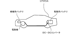
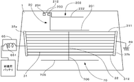
- FIG. 1 is a schematic view of a hybrid vehicle on which a glass antenna according to this embodiment is mounted
- FIG. 2 is a front view of a rear glass of the hybrid vehicle of FIG.
- this hybrid vehicle uses an engine and an electric motor as driving sources, and a driving battery for the electric motor is disposed at the rear portion of the vehicle, that is, near the trunk.
- an auxiliary battery for in-vehicle equipment such as ECU and ABS is disposed at the front of the vehicle.
- a DC-DC converter for converting the high voltage DC voltage of the driving battery into a low voltage DC voltage suitable for the auxiliary battery (for example, 12V) and supplying the converted voltage to the auxiliary battery.
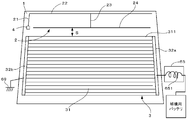
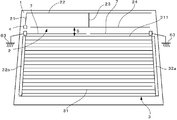
- the glass antenna according to this embodiment is disposed on the rear glass 1 of the hybrid vehicle, and includes an FM antenna element 2 and a defogger 3 (heater).
- a feeding terminal 4 is provided at a position closer to the upper side than the center of the left edge of the rear glass 1, and the FM antenna element 2 is connected to the feeding terminal 4.
- the FM antenna element 2 includes a first vertical element 21 extending upward from the power supply terminal 4 and a first horizontal element 22 extending in the horizontal direction from the upper end of the first vertical element 21.
- the first vertical element 21 extends to the vicinity of the upper end of the rear glass 1, and the first horizontal element 22 extends in the horizontal direction along the upper end of the rear glass 1.
- the FM antenna element 2 includes a second vertical element 23 extending downward from the center of the first horizontal element 22 and a second horizontal element 24 connected to the lower end of the second vertical element 23 and extending in the horizontal direction. ing.
- the lower end portion of the second vertical element 24 is disposed at substantially the same position as the power supply terminal 4 in the vertical direction.
- the second horizontal element 24 connected to the second vertical element 23 constitutes the lowermost part of the FM antenna element 2.
- horizontal means a direction substantially parallel to the installation surface of the vehicle
- vertical means a direction substantially orthogonal to “horizontal”. Therefore, “horizontal” and “vertical” do not necessarily indicate strict directions. For example, even if “horizontal” is referred to, it may not be strictly parallel to the installation surface of the vehicle but may be slightly inclined. .
- the meanings of “horizontal” and “vertical” are the same for the defogger described below and each embodiment described later.
- the defogger 3 is mounted below the second horizontal element 24 of the FM antenna element 2 and includes a plurality of horizontal elements (heating lines) 31.
- the defogger 3 includes a pair of power supply bus bars 32 a and 32 b extending in the vertical direction along both side edges of the rear glass 1.
- the right bus bar 32a is supplied with power from an auxiliary battery (not shown), and the left bus bar 32b is connected to a vehicle ground (not shown).
- a plurality of horizontal elements 31 are disposed in parallel between the bus bars 32a and 32b at a predetermined interval, and heat for anti-fogging is generated by power feeding from the bus bars 32a and 32b. ing.
- the uppermost horizontal element 311 of the defogger 3 and the second horizontal element 24 at the lowermost part of the FM antenna element 2 are substantially parallel to each other, so that both elements 311 and 24 are capacitively coupled. ing. Therefore, the defogger 5 functions as an antenna together with the FM antenna element 2 in addition to fulfilling the anti-fogging function.
- the distance S between the defogger horizontal element 311 and the second horizontal element 24 of the FM antenna element 2 is preferably greater than 40 mm, more preferably 50 mm or more, and particularly preferably 60 mm or more. .
- Each antenna element described above is made of a known conductive material and is mounted on the glass surface by screen printing or the like.
- the glass antenna configured as described above has the following effects. That is, in the hybrid vehicle as described above, a DC-DC converter is provided, and when this converter is driven, radiation noise is generated. Since this DC-DC converter is disposed in the rear part of the vehicle close to the rear glass, the generated radiation noise affects the defogger 3 having a large area. However, since the distance S between the defogger 3 and the FM antenna element 2 is larger than 40 mm as described above, it is possible to reduce the influence of noise that has affected the defogger 3 on the FM antenna element 2. .
- the reception sensitivity of the FM antenna element 2 is improved in addition to the noise reduction in the FM antenna element 2.
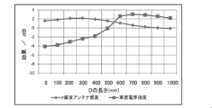
- the greater the distance S the better the reception sensitivity in the entire frequency range of FM radio waves.
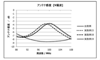
- the reception sensitivity in the overseas frequency band of 88 to 108 MHz is improved. It has been found to improve. Note that this improvement in reception sensitivity is realized by increasing the distance S not only in a hybrid vehicle equipped with a DC-DC converter but also in a vehicle driven by a normal engine.
- the shape of the FM antenna element according to the above embodiment and the shape of the defogger 3 are only examples, and various other shapes are possible as long as at least the distance S between them is larger than 40 mm and capacitively coupled. .
- another element may be added to the FM antenna element 2 or a vertical element may be appropriately added to the defogger 3.
- the FM antenna element is mounted as the antenna element.
- the present invention is not limited to this, and an FM sub antenna element, an AM antenna element, a key antenna element for keyless entry, and the like are appropriately used. It can also be provided. This point is the same in the following embodiments.
- the hybrid vehicle shown in the above embodiment is an example, and the present invention is not limited to this. That is, the glass antenna according to the above embodiment can be applied not only to a hybrid vehicle but also to other vehicles, that is, applicable to various noise sources. This point is the same in the following embodiments.
- Example A Hereinafter, Example A will be described. However, this Example A is an example and does not limit Invention 1.
- the following examples and comparative examples having different distances S were prepared.
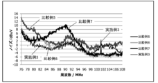
- this glass antenna is provided in a hybrid vehicle having a DC-DC converter mounted on the rear portion as shown in FIG.
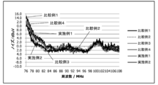
- the center frequency of radiation noise generated in this DC-DC converter was 76 MHz.
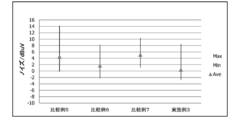
- FIG. 4 shows noise in the domestic frequency band of 76 to 90 MHz extracted from FIG. 3, and shows the noise ranges and averages of the example and the comparative example in this frequency band. According to FIG. 4, it can be seen that when the distance S is larger than 40 mm, the maximum value of noise is lowered. This tendency can be seen up to around 83 MHz.
- the distance S which is the feature of the present invention, is made larger than 40 mm. Is meaningful.
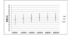
- FIG. 5 shows the reception sensitivity in the entire frequency range.
- FIG. 6 shows the range and average of the reception sensitivity of each example and comparative example based on FIG. According to FIGS. 5 and 6, it can be seen that the reception sensitivity is improved as the distance S is increased. In particular, when the distance S is larger than 40 mm, the reception sensitivity in the overseas frequency band of 88 to 108 MHz is improved. Therefore, the average reception sensitivity in all frequency ranges is improved as the distance S is increased. I understood.
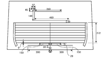
- FIG. 7 is a front view of the rear glass according to the present embodiment.
- the glass antenna according to the present embodiment has substantially the same configuration as that of the glass antenna according to the first embodiment.
- the distance between the FM antenna element 2 and the defogger 3 is not particularly limited, and may be 40 mm or less.
- a noise filter including a coil (RFC: Radio : Frequency Choke Coil) 651 between the right bus bar (anode bus bar) 32a and the auxiliary battery. 65 is connected.
- a noise filter is not connected between the left bus bar (cathode bus bar) 32 b and the vehicle body ground 69.
- the noise filter 65 is for preventing noise from flowing into the defogger 3 from the auxiliary battery side. That is, since the defogger 3 is capacitively coupled to the FM antenna element 2 and functions as an FM antenna, the noise of the FM antenna element 2 can be reduced by providing such a noise filter.
- the inductance of the coil 651 of the noise filter 65 is preferably, for example, 0.5 to 5.0 ⁇ H, and more preferably 0.7 to 2.0 ⁇ H. Moreover, in this embodiment, since the feeding terminal 4 of the FM antenna element 2 is arranged on the opposite side to the bus bar 32a on the feeding side, this also reduces the noise that the FM antenna element 2 can receive. Yes.
- the noise filter is not provided on the left bus bar 32b connected to the vehicle body ground.
- the defogger 3 of the glass antenna is easily affected by radiation noise from the DC-DC converter.
- a noise filter is provided also on the vehicle body ground 69 side, the radiation noise received by the defogger 3 is stopped by the noise filter on the vehicle body ground 69 side, and it is considered that noise does not flow out to the vehicle body ground 69 side.
- radiation noise accumulates in the defogger 3, and the FM antenna element 2 is considered to be affected by this noise. Therefore, the noise filter is not provided on the left bus bar 32b side.
- the shape of the FM antenna element according to the above embodiment and the shape of the defogger 3 are examples, and various other shapes are possible as long as at least both are capacitively coupled.
- another element may be added to the FM antenna element 2 or a vertical element may be appropriately added to the defogger 3.
- Example B ⁇ 3.
- Example B> Hereinafter, Example B will be described. However, this Example B is an example and does not limit Invention 2.
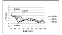
- the distance S was set to 60 mm, and the following examples and comparative examples were prepared. That is, in the example and the comparative example, a noise filter including RFC is disposed between the right bus bar and the auxiliary battery, and between the left bus bar and the vehicle body ground side. Also not arranged.
- this glass antenna is provided in a hybrid vehicle having a DC-DC converter mounted on the rear portion as shown in FIG. The center frequency of radiation noise generated in this DC-DC converter was 76 MHz.
- FIG. 9 shows noise in the domestic frequency band of 76 to 90 MHz extracted from FIG. 8, and shows the noise ranges and averages of the example and the comparative example in this frequency band. 8 and 9, it can be seen that the noise in the domestic frequency band is reduced in Example 3 compared to Comparative Examples 5-7. For example, it can be seen that the average value of noise is lower than that of Comparative Example 6 in which noise filters are provided on both sides of the bus bar.
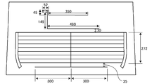
- FIG. 10 is a front view of the rear glass according to the present embodiment.
- the glass antenna according to the present embodiment has substantially the same configuration as that of the glass antenna according to the first embodiment.
- the distance between the FM antenna element 2 and the defogger 3 is not particularly limited, and may be 40 mm or less.
- two linear noise removal elements 7 extending in the horizontal direction are provided between the FM antenna element 2 and the defogger 3. These noise removal elements 7 are arranged at predetermined intervals along the horizontal direction.
- the interval between the noise removal elements is not particularly specified, but can be freely designed within a range of 10 to 200 mm, for example.
- the length of the noise removal element 7 is not particularly limited, but can be, for example, about ⁇ / 4 ⁇ 50 mm, preferably ⁇ 30 mm with respect to the above-described center frequency F.
- These noise removal elements 7 are each connected to a vehicle body ground 63.
- the noise removal element 7 is formed of the same material as the FM antenna element 2 and the defogger 3.
- noise received by the FM antenna element 2 can be reduced.
- each of the noise removal elements 7 is connected to the vehicle body ground 69, but the connection to the vehicle body ground 69 is not essential and may not be connected.
- Example C ⁇ 3.
- Example C> Hereinafter, Example C will be described. However, this Example C is an example and does not limit Invention 3.
- the distance S was set to 60 mm, and the following examples and comparative examples were prepared.
- the distance between the noise removal element and the defogger is 10 mm. That is, in Example 4, two noise removal elements were provided and each was connected to the vehicle body ground. The length of each noise removal element is 530 mm, and the horizontal interval between both noise removal elements is 12 mm. Further, in Example 5, two noise removal elements are provided, but they are not connected to the vehicle body ground. Further, in Comparative Example 8, no noise removal element is provided.
- this glass antenna is provided in a hybrid vehicle having a DC-DC converter mounted on the rear portion as shown in FIG. The center frequency F of radiated noise generated in this DC-DC converter was 83 MHz. Then, with the wavelength ⁇ of the center frequency F as a reference, the length of each noise removal element of Examples 4 and 5 was set to ⁇ / 4 mm.
- FIG. 12 is a front view of the rear glass according to the present embodiment.
- the glass antenna according to the present embodiment is disposed on the rear glass 1 of the hybrid vehicle, and includes an FM antenna element 2 and a defogger 3 (heater).
- a feeding terminal 4 is provided at a position closer to the upper side than the center of the right edge of the rear glass 1, and the FM antenna element 2 and the AM antenna element 8 are connected to the feeding terminal 4.
- the FM antenna element 2 is disposed above the AM antenna element 8, and the defogger 3 is disposed below the AM antenna element 8. That is, the AM antenna element 8 is arranged between the FM antenna element 2 and the defogger 3.
- the FM antenna element 1 includes a first vertical element 25 extending upward from the power supply terminal 4 and a first horizontal element 26 extending horizontally from the upper end of the first vertical element 25. Further, an L-shaped first L-shaped element 27 is connected from a position on the left side of the center of the first horizontal element 26, and in the first L-shaped element 27, in the vicinity of the center of the rear glass 1, the same L-shape. A second L-shaped element 28 of the mold is connected. The second L-shaped element 28 is longer in the vertical direction than the first L-shaped element 27, and its left end extends to the vicinity of the power supply terminal 4. A second horizontal element 29 extending to the left side is connected to the left end portion of the second L-shaped element 28 via a short folded portion 281 extending upward.
- the AM antenna element 8 includes a first vertical element 81 extending downward from the power supply terminal 4, and a stub 9 in which an antenna line is folded is connected to a lower end portion of the first vertical element 81.
- the stub 9 will be described later.
- a first horizontal element 82 extending to the left side is connected to the stub 9.
- a second vertical element 83 extending upward is connected near the center of the first horizontal element 82, and a second horizontal element 84 extending leftward is connected to the upper end portion of the second vertical element 83.
- the dimensions of the antenna element are not particularly limited.
- the distance A4 between the first horizontal element of the AM antenna element and the second L-shaped element 28 of the FM antenna element is 60 mm, and the second L-shaped element of the FM antenna element.
- the distance A5 between 28 and the first horizontal element 26 can be 60 mm.
- the stub is formed by bending the antenna line as described above, and constitutes a parallel resonance circuit.
- This parallel resonant circuit has a function of passing a reception signal in the frequency band of AM broadcasting and blocking or attenuating the reception signal in the frequency band of FM broadcasting.
- the stub 9 constituting such a parallel resonant circuit can have various patterns. Specifically, it is shown in FIG. FIG. 13A is a diagram in which one end portions of first and second antenna lines 91 and 92 extending in parallel are connected to each other (hereinafter referred to as stub pattern 1). In addition, it can be said that the stub pattern 1 has one folded portion of the antenna wire.
- FIG. 13B is the stub shown in FIG. 12. In the stub pattern 1, the third stub passes from the base end of the second antenna line 92 between the first and second antenna lines 91 and 92.
- the antenna wire 93 is extended to the connecting portion (hereinafter referred to as stub pattern 2).
- the stub pattern 2 has two folded portions of the antenna line.
- FIG. 13C shows the base end of the second antenna line 92 so that it passes between the second antenna line 92 and the third antenna line from the end of the third antenna line 93 in the stub pattern 2.
- a fourth antenna line 94 extending to the portion is provided (hereinafter referred to as stub pattern 3).
- the stub pattern 3 has three folded portions of the antenna line.
- the defogger 3 is substantially the same as that of the first embodiment, but the bus bar is different. That is, in this embodiment, power is supplied from the auxiliary battery to the left bus bar 32b, and the right bus bar 32a is connected to the vehicle body ground.
- the uppermost horizontal element 311 of the defogger 3 and the second L-shaped element 28 at the lowermost part of the FM antenna element 2 are substantially parallel to each other, so that both elements 311 and 28 are capacitively coupled. is doing. Therefore, the defogger 5 functions as an antenna together with the FM antenna element 2 in addition to fulfilling the anti-fogging function.
- the distance S between the horizontal element 311 of the defogger 3 and the second L-shaped element 28 of the FM antenna element 2 is not particularly limited.
- the distance S is preferably larger than 40 mm, and more preferably 50 mm or more. Preferably, it is 60 mm or more.
- Each antenna element described above is made of a known conductive material and is mounted on the glass surface by screen printing or the like.
- the glass antenna configured as described above has the following effects.
- the antenna pattern constituting the parallel resonance circuit, that is, the stub 9 is connected to the AM antenna element 8.
- the noise in the frequency band of FM broadcasting is prevented from flowing into the FM antenna element 2 side, that is, the feeding terminal 4.
- a hybrid vehicle such as this embodiment is provided with a DC-DC converter, and when this converter is driven, radiation noise is generated.
- the AM antenna element 8 easily receives noise, but by providing the stub 9 as described above, the noise in the FM antenna element 2 can be blocked or reduced.
- the noise received by the FM antenna element 2 can be reduced by separating the distance S between the FM antenna element 2 and the defogger 3 as shown in the first embodiment. If the AM antenna element 8 is disposed between the FM antenna element 2 and the defogger 3, a new problem arises in that noise received by the AM antenna element 8 affects the FM antenna element 2. Therefore, in the present embodiment, the stub 9 described above is provided so that the noise received by the FM antenna element 2 can be cut off or reduced even if the AM antenna element 8 is provided.
- the folds can be shortened as the number of folded portions increases, whereby the following effect can be obtained.
- the more the stub 9 is folded the shorter the length, and the longer the distance between the power supply side bus bar 32 b and the stub 9. Therefore, the noise which stub 9 itself receives from electric power feeding side bus bar 32b can be reduced.
- the shape of the FM antenna element 1, the shape of the AM antenna element 8, and the shape of the defogger 3 according to the above embodiment are merely examples, and other various shapes are possible. It is sufficient that the AM antenna element 8 is disposed at least between the FM antenna element and the defogger, and the FM antenna element 2 and the defogger 3 are capacitively coupled.
- the FM antenna element 1 and the AM antenna element 8 are connected to one feeding terminal 4, but for example, two feeding elements are provided, and the antenna elements 1 and 8 are connected to each. You can also. Even in such a case, the noise received by the AM antenna element 8 is, for example, FM via a lead wire for the FM antenna element that is close before being transmitted from the power supply terminal to the AM amplifier. There is a possibility of entering the amplifier. Therefore, it is effective to provide the AM antenna element 8 with the stub 9 even if it is a glass antenna in which a feeding terminal is provided for each of the antenna elements 1 and 8.
- the shape of the stub is not particularly limited, and shapes other than those described above are possible. That is, it may have four or more folded portions.
- Example D ⁇ 4.
- Example D> Hereinafter, Example D will be described. However, this Example D is an example and does not limit Invention 4.
- the shape of the stub will be examined.
- the sixth embodiment stub pattern 1 corresponding to FIG. 13A
- the seventh embodiment stub pattern 2) corresponding to FIG. 13B
- the eighth embodiment corresponding to FIG. 13C (stub). Pattern 3) was used to measure radio wave transmission loss.
- the dimensions of the stubs in each example are as follows. The design is based on 83 Hz.
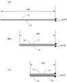
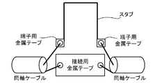
- the method for measuring radio wave transmission loss is as shown in FIG. That is, 5 mm square metal tapes for terminals were placed on the terminal portions at both ends of each stub, and each was connected to a coaxial cable. Further, a connecting metal tape having a width of 20 mm and a length of 10 mm was disposed between both coaxial cables, and was electrically connected to each coaxial cable. In addition, the stub and the metal tape were arrange
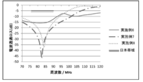
- Example 6 shows a radio wave cut effect in the entire region including the overseas frequency band, but Examples 7 and 8 particularly cut radio waves in the domestic frequency band of 76 to 90 MHz. It turns out that the effect is high.
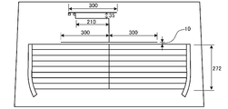
- FIG. 16 is a front view of the rear glass according to the present embodiment.
- the glass antenna according to the present embodiment is arranged on the rear glass 1 of the hybrid vehicle, and the FM antenna element 20, the defogger 3 (heater heater), and the noise suppression element from the upper side to the lower side. 70 are arranged in this order.
- the FM antenna element 20 is a so-called bipolar antenna, and includes an antenna body element 201 and a ground connection element 202.
- the antenna body element 201 is formed in an L shape, and extends downward from a power supply terminal 203 disposed near the center of the upper edge of the rear glass 1.
- the ground connection element 202 extends to the right from the ground connection terminal 204 arranged on the left side of the power supply terminal 203.
- a first part 212 that extends horizontally to the right side over the power supply terminal 203 and a second part 222 that extends rightward from the right end of the first part 212 to the right side on the right side of the power supply terminal 203.
- the ground connection terminal 204 is connected to a vehicle body ground (not shown).
- the antenna body element 201 extends to the right side of the second part 222 of the ground connection element 202.
- the defogger 3 is mounted below the antenna body element 24 of the FM antenna element 2, and includes a pair of power supply bus bars 32 a and 32 b extending in the vertical direction along both side edges of the rear glass 1.
- the left bus bar (anode bus bar) 32 a is supplied with power from the auxiliary battery, and the right bus bar (cathode bus bar) 32 b is connected to the vehicle body ground 69.
- a noise filter 65 similar to that shown in the second embodiment is disposed between the auxiliary battery and the bus bar 32a.
- a plurality of horizontal elements 31 are arranged in parallel at a predetermined interval. Further, a vertical element 32 is disposed between the bus bars 32 a and 32 b and intersects with the plurality of horizontal elements 31. That is, the vertical element 32 extends from the uppermost horizontal element 311 to the lowermost horizontal element 312.
- the horizontal element 31 configured in this manner is configured to generate anti-fogging heat by power feeding from the bus bars 32a and 32b.
- the vertical element 32 is not supplied with power and does not contribute to heating, but functions as one of the FM antenna receivers.
- the uppermost horizontal element 311 of the defogger 3 and the antenna main body element 201 of the FM antenna element 2 are substantially parallel to each other, so that both the elements 311 and 201 are capacitively coupled. Therefore, the defogger 5 functions as an FM antenna receiving unit together with the FM antenna element 2 in addition to performing an anti-fogging function.
- the noise suppression element 70 described above is disposed below the defogger 3.
- the noise suppression element 70 includes a first part 701 extending in parallel with the lowermost horizontal element 311 of the defogger 3, a second part 702 extending in parallel with the first part 701 below the first part 701, and a first part 701.
- a third portion 703 that extends downward from the center of the first portion and further extends downward while intersecting with the second portion 702.
- the first portion 701 is close to the lowermost horizontal element 312 of the defogger 3, whereby the noise suppression element 70 is capacitively coupled to the defogger 3.
- the second part 702 is longer in the horizontal direction than the first part 701.
- the third portion 703 is arranged at a position corresponding to the vertical element 32 of the defogger, and a ground connection terminal 704 is connected to a lower end portion thereof.
- the ground connection terminal 704 is connected to the vehicle body ground 69.
- the noise suppression element 70 functions as an antenna, and, as will be described below, the array antenna is configured in cooperation with the FM antenna element 20. be able to.
- the noise suppression element 70 is made of the same material as the FM antenna element 2 and the defogger 3.
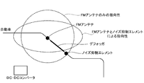
- the FM antenna element 20 and the noise suppression element 70 can constitute an array antenna. Thereby, the noise received by the FM antenna element 2 can be suppressed, and the sensitivity of the antenna can be improved. This point will be described with reference to FIG.
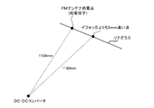
- FIG. 17 is a cross-sectional view showing the vicinity of the rear glass of an automobile.
- the directivity is substantially circular in a side view.
- the directivity of the FM antenna element 20 is an elliptical shape that extends in the front and rear of the vehicle so as to be crushed up and down. It becomes.
- the directivity range of the FM antenna element 20 is separated from the DC-DC converter by providing the noise suppression element 20, so that radiation noise from the DC-DC converter (for example, a passenger compartment electric field of an embodiment described later) Strength) can be suppressed.
- a distance (this distance will be described later) between the FM antenna element 20 and the noise suppression element 70 is 1 ⁇ 4 ⁇ or more.
- the phase difference between the two may also be affected, so it is preferable to adjust as appropriate.
- FIG. 17 is an example that schematically represents the directivity of the FM antenna element, and does not represent the actual directivity range.
- the directivity of the FM antenna element 20 can be controlled by providing the noise suppression element 70 at a position away from the FM antenna element 20, for example, at a position separated by at least a half wavelength (1 / 2 ⁇ ).
- the defogger 3 can be disposed between the FM antenna element 20 and the noise suppression element 70 which are spaced apart from each other, the rear glass 1 having a limited area can be effectively used.
- the defogger 3 can function as a part of the antenna.
- an FM band element length for example, about 1 m
- the defogger 3 functions as an antenna by capacitive coupling,
- the noise suppression element 70 can be made compact. Note that in order for the FM antenna element 20 and the noise suppression element 70 to function as an array antenna, it is necessary that there is a certain distance (for example, about a half wavelength) between them.
- the distance between the centers that is, the distance between the feeding point (feeding terminal 203) of the FM antenna element 20 and the feeding point (ground connection terminal 704) of the noise suppression element 70 in the example of the present embodiment. Therefore, even if the defogger 3 is arranged between them and capacitively coupled to the noise suppression element 70, the performance of the array antenna is not affected.
- the noise suppression element 70 is connected to the vehicle body ground 69 as described above, the directivity of the FM antenna element 20 can be easily controlled. In addition, since the grounding is performed through the vehicle body, the grounding is facilitated. Further, a resistor may be provided instead of the ground.
- the third portion 703 extending vertically of the noise suppression element 70 is disposed at a position corresponding to the vertical element 32 of the defogger, it is easier to make the noise suppression element function as an antenna.
- the strength of capacitive coupling between the noise suppression element 70 and the defogger 3 is changed by changing the length of the first portion 701 of the noise suppression element 70 and the distance between the horizontal element 311 of the defogger 3 and the first portion 701.
- the performance of the noise suppression element 70 as an antenna can be adjusted. That is, by adjusting these, the directivity of the FM antenna element 20 as an array antenna can be adjusted. This point will be described later in Example F.
- the noise suppression element 70 is connected to the vehicle body ground 69, but it is not always necessary to connect it.
- a noise filter 65 can also be provided between the right bus bar 32 b and the vehicle body ground 69. However, the noise filter 65 is not essential and may not be provided.
- the shape of the noise suppression element 70 is not particularly limited as long as the noise suppression element 70 is disposed on the opposite side of the FM antenna element 20 with the defogger 3 interposed therebetween.
- an embodiment as shown in FIG. 18 can be adopted.
- the noise suppression element 70 is connected to the lower end portion of the vertical element 32 of the defogger 3 and extends horizontally from the first portion 706 extending downward and the lower end portion of the first portion 706.
- the second portion 705 is provided and formed as a T-shape as a whole. That is, the noise suppression element 70 is directly connected to the defogger 3. Therefore, the noise suppression element 70 may be capacitively coupled to the defogger 3 or may be directly coupled.
- the noise suppression element 70 can also be comprised.
- the noise suppression element 70 is configured only by the second portion 702.
- a noise suppression element is provided by providing a fourth portion 704 that is substantially the same length as the first portion 701 and extends in parallel with the first portion 701 and the second portion 702. 70 is configured.
- a trapezoidal noise suppression element 70 is configured by providing a fifth portion 708 that connects both ends of the first portion 701 and the second portion 702.
- the example of FIG. 19D is provided with a third portion 703 that extends vertically in the example of FIG. In the example of FIG.
- the first portion 701, the second portion 702, and the third portion 703 are provided, and further, a sixth portion 709 that connects these both ends is provided, and the noise suppression element 70 is provided. Is configured. And in the example of FIG.19 (f), the 3rd site
- All the noise suppression elements 70 as described above are disposed immediately below the defogger 3 and are capacitively coupled to the defogger 3.
- the FM antenna element 20 may be a single pole type instead of the hyperbolic type as described above. Further, the shape of the FM antenna element 20 is not particularly limited. Furthermore, the FM antenna element 20 may be capacitively coupled to the defogger 3 or directly coupled as in the above embodiment.
- the shape of the defogger 3 is not particularly limited, and at least one vertical element 32 is sufficient.
- the FM antenna element 20 is disposed above the defogger 3.
- the FM antenna element 20 may be disposed below the defogger 3 and the noise suppression element 70 may be disposed above the defogger 3.
- Example E ⁇ 4.
- Example E> Hereinafter, Example E will be described. However, this Example E is an example and does not limit Invention 5.
- FIG. 20 is a diagram showing the dimensions of Examples 9 to 11
- FIG. 21 is a diagram showing the dimensions of Example 12
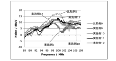
- FIG. 22 is a diagram showing Comparative Example 9. In either case, the unit in the figure is mm.
- FIG. 24 shows the reception sensitivity in the entire frequency range.
- the receiving sensitivity is generally higher than that of Comparative Example 9.
- the reception sensitivity of Example 11 was lower than that of Comparative Example 9. Therefore, although Example 11 had the noise suppression effect compared with the comparative example, the receiving sensitivity became low.
- the connection to the vehicle body ground is preferable in the aspect in which the noise suppression element is capacitively coupled to the defogger as in the eleventh embodiment.
- the noise suppression element is preferably connected to the ground of the vehicle body, it has been found that the capacitive coupling with the defogger generally gives better results.
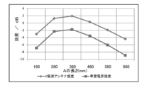
- Example F Hereinafter, Example F will be described. However, this Example F is an example and does not limit Invention 5.
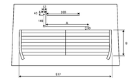
- the window glass (corresponding to FIG. 16) shown in FIG. 25 was prepared as an example.
- the sensitivity of the antenna was measured while changing the dimensions of the FM antenna element, the defogger, and the noise suppression element.
- an electric field corresponding to the DC-DC converter was generated from the position of FIG. 26, and the electric field strength received from the electric field was measured.
- a window glass not provided with a noise suppression element as shown in FIG. 27 was used as a comparative example.
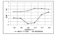
- the electric field strength in the passenger compartment is lower than that in the comparative example even if the length B is changed.
- the length of B is 232 to 272 mm
- the vehicle compartment electric field strength is particularly reduced as compared with other lengths.
- the FM wave reception sensitivity from the outside of the vehicle is generally improved as compared with the comparative example.
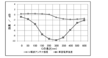
- the electric field strength in the passenger compartment is lower than that in the comparative example even if the length C is changed.
- the electric field strength of the passenger compartment is particularly reduced as compared with other lengths.
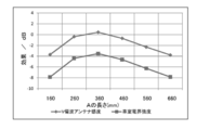
- the reception sensitivity of FM waves from the outside of the vehicle is generally improved as compared with the comparative example.
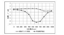
- the vehicle compartment electric field strength is lower than that of the comparative example even if the length D is changed.
- the length of D is 500 to 700 mm
- the cabin electric field strength is particularly reduced as compared with other lengths.
- the reception sensitivity of FM waves from the outside of the vehicle is generally improved as compared with the comparative example.
- Example G ⁇ 6.
- Example G ⁇ 6.
- Example G ⁇ 6.
- Example G ⁇ 6.
- Example G is an example and does not limit Invention 5.
- the window glass shown in FIG. 25 was prepared as Example 14.
- the shape of the noise suppression element in FIG. 25 was changed to the form shown in FIG. 18 as shown in the following table.
- the length of the first part was 100 mm
- the lengths of the second and third parts were 200 mm.
- the sensitivity of the antenna was measured, and an electric field corresponding to the DC-DC converter was generated from the position in FIG.
- a window glass having no noise suppression element shown in FIG. 27 was prepared.
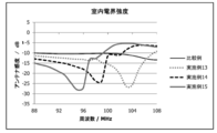
- the cabin electric field strength from the DC-DC converter is lower than that of the comparative example in almost all examples, but particularly in Example 13 with a small number of elements,
- the vehicle compartment electric field strength is lower than that of the comparative example. It can also be seen that the greater the number of horizontally extending elements, the lower the cabin field strength in the low frequency range.
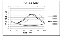
- Example 14 which does not have the fifth portions at both ends, has high reception sensitivity in the high frequency range.
- the cabin electric field strength from the DC-DC converter is generally in a low frequency range, and Examples 14, 16, and 17 are lower than the comparative examples.
- Example 14 the electric field strength in the passenger compartment is lower than in the comparative example except for the high frequency range.
- Examples 16 and 17 had almost the same results. That is, it was found that the presence or absence of the vertical element at the center does not greatly affect the sensitivity.
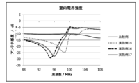
- the electric field strength of the passenger compartment from the DC-DC converter is generally in a low frequency region, and Examples 15, 18, and 19 are lower than the comparative example. Examples 15 and 19 had almost the same results. That is, it was found that the presence or absence of the sixth portion does not greatly affect the sensitivity.
Landscapes
- Engineering & Computer Science (AREA)
- Remote Sensing (AREA)
- Chemical & Material Sciences (AREA)
- Combustion & Propulsion (AREA)
- Transportation (AREA)
- Mechanical Engineering (AREA)
- Computer Networks & Wireless Communication (AREA)
- Signal Processing (AREA)
- Details Of Aerials (AREA)
- Support Of Aerials (AREA)
- Fittings On The Vehicle Exterior For Carrying Loads, And Devices For Holding Or Mounting Articles (AREA)
- Hybrid Electric Vehicles (AREA)
Priority Applications (5)
| Application Number | Priority Date | Filing Date | Title |
|---|---|---|---|
| EP16786590.6A EP3291370A4 (en) | 2015-04-28 | 2016-04-28 | Glass antenna |
| US15/567,677 US20180123219A1 (en) | 2015-04-28 | 2016-04-28 | Glass antenna |
| JP2017515625A JPWO2016175314A1 (ja) | 2015-04-28 | 2016-04-28 | ガラスアンテナ |
| CN201680024449.9A CN107534208A (zh) | 2015-04-28 | 2016-04-28 | 玻璃天线 |
| US16/592,475 US10608318B2 (en) | 2015-04-28 | 2019-10-03 | Glass antenna |
Applications Claiming Priority (4)
| Application Number | Priority Date | Filing Date | Title |
|---|---|---|---|
| JP2015-092326 | 2015-04-28 | ||
| JP2015092326 | 2015-04-28 | ||
| JP2015183499 | 2015-09-16 | ||
| JP2015-183499 | 2015-09-16 |
Related Child Applications (2)
| Application Number | Title | Priority Date | Filing Date |
|---|---|---|---|
| US15/567,677 A-371-Of-International US20180123219A1 (en) | 2015-04-28 | 2016-04-28 | Glass antenna |
| US16/592,475 Continuation US10608318B2 (en) | 2015-04-28 | 2019-10-03 | Glass antenna |
Publications (1)
| Publication Number | Publication Date |
|---|---|
| WO2016175314A1 true WO2016175314A1 (ja) | 2016-11-03 |
Family
ID=57198502
Family Applications (1)
| Application Number | Title | Priority Date | Filing Date |
|---|---|---|---|
| PCT/JP2016/063461 Ceased WO2016175314A1 (ja) | 2015-04-28 | 2016-04-28 | ガラスアンテナ |
Country Status (5)
| Country | Link |
|---|---|
| US (2) | US20180123219A1 (enExample) |
| EP (1) | EP3291370A4 (enExample) |
| JP (4) | JPWO2016175314A1 (enExample) |
| CN (1) | CN107534208A (enExample) |
| WO (1) | WO2016175314A1 (enExample) |
Cited By (5)
| Publication number | Priority date | Publication date | Assignee | Title |
|---|---|---|---|---|
| JP2019114991A (ja) * | 2017-12-25 | 2019-07-11 | 日本板硝子株式会社 | 車両用窓ガラス |
| CN110168805A (zh) * | 2017-01-11 | 2019-08-23 | 日本板硝子株式会社 | 窗玻璃 |
| JP2020161975A (ja) * | 2019-03-26 | 2020-10-01 | Agc株式会社 | 車両用ガラス |
| JP2023514639A (ja) * | 2020-02-25 | 2023-04-06 | ピルキントン グループ リミテッド | アンテナを備えるグレージング、その製造方法およびその使用 |
| WO2025047227A1 (ja) * | 2023-08-25 | 2025-03-06 | 日本板硝子株式会社 | 車両用ガラスアンテナ |
Families Citing this family (6)
| Publication number | Priority date | Publication date | Assignee | Title |
|---|---|---|---|---|
| EP3480888B1 (en) * | 2016-07-01 | 2024-12-11 | Nippon Sheet Glass Company, Limited | Vehicle window glass |
| JP7204736B2 (ja) * | 2018-03-16 | 2023-01-16 | 日本板硝子株式会社 | リアガラス |
| KR20200113580A (ko) * | 2019-03-26 | 2020-10-07 | 현대자동차주식회사 | 글라스 열선 구조 |
| CN111987425B (zh) * | 2020-08-21 | 2021-12-21 | 福耀玻璃工业集团股份有限公司 | 天线组件、天线玻璃及车辆 |
| TWI765667B (zh) * | 2021-04-19 | 2022-05-21 | 啟碁科技股份有限公司 | 天線結構 |
| JP7677048B2 (ja) * | 2021-08-04 | 2025-05-15 | Agc株式会社 | 車両用窓ガラス |
Citations (2)
| Publication number | Priority date | Publication date | Assignee | Title |
|---|---|---|---|---|
| JP2005130415A (ja) * | 2003-10-27 | 2005-05-19 | Central Glass Co Ltd | 車両用ガラスアンテナ |
| JP2012066658A (ja) * | 2010-09-22 | 2012-04-05 | Honda Motor Co Ltd | アースシステム |
Family Cites Families (19)
| Publication number | Priority date | Publication date | Assignee | Title |
|---|---|---|---|---|
| JPS52147622A (en) * | 1976-06-03 | 1977-12-08 | Toyota Motor Co Ltd | Window glass having defogger hot wire for vehicles |
| US4063247A (en) * | 1976-10-07 | 1977-12-13 | Nippon Sheet Glass Co., Ltd. | Heater glass sheet with broad band receiver antennae |
| JPH0349443Y2 (enExample) * | 1985-10-03 | 1991-10-22 | ||
| JPH0349447Y2 (enExample) * | 1987-02-10 | 1991-10-22 | ||
| GB2266189B (en) * | 1992-04-08 | 1996-09-11 | Antiference Ltd | Vehicle antenna |
| JPH06197036A (ja) * | 1992-12-25 | 1994-07-15 | Suzuki Motor Corp | ガラスアンテナ用ノイズフィルタ |
| JPH09191208A (ja) * | 1996-01-09 | 1997-07-22 | Asahi Glass Co Ltd | 自動車用ガラスアンテナ |
| JP3608890B2 (ja) * | 1996-12-06 | 2005-01-12 | セントラル硝子株式会社 | 自動車用ガラスアンテナ |
| TW423180B (en) | 1997-01-31 | 2001-02-21 | Terajima Fumitaka | Glass antenna device for an automobile |
| JP3700372B2 (ja) * | 1997-01-31 | 2005-09-28 | 旭硝子株式会社 | 車両用ガラスアンテナ装置 |
| JPH11127013A (ja) * | 1997-10-23 | 1999-05-11 | Asahi Glass Co Ltd | 自動車ガラスアンテナ用端子装置 |
| JP2004260504A (ja) | 2003-02-26 | 2004-09-16 | Yazaki Corp | 車両用アンテナ構造 |
| JP2006101386A (ja) * | 2004-09-30 | 2006-04-13 | Nippon Sheet Glass Co Ltd | 車両用ガラスに形成されるデフォッガの熱線パターン構造および車両用ガラスアンテナ |
| DE102005039914A1 (de) | 2005-08-24 | 2007-03-08 | Robert Bosch Gmbh | Mehrbereichs-Antennenanordnung |
| JP2009111704A (ja) | 2007-10-30 | 2009-05-21 | Honda Motor Co Ltd | 車両用受信設備 |
| JP5109089B2 (ja) | 2008-06-20 | 2012-12-26 | 旭硝子株式会社 | 車両用ガラスアンテナ及び車両用窓ガラス |
| CN101345333B (zh) * | 2008-08-25 | 2012-05-23 | 蒋小平 | 一种汽车后窗玻璃印制天线系统 |
| JP2011049825A (ja) * | 2009-08-27 | 2011-03-10 | Honda Motor Co Ltd | 車両用受信設備 |
| JP2011105270A (ja) | 2009-11-20 | 2011-06-02 | Toyota Motor Corp | 車両 |
-
2016
- 2016-04-28 CN CN201680024449.9A patent/CN107534208A/zh active Pending
- 2016-04-28 US US15/567,677 patent/US20180123219A1/en not_active Abandoned
- 2016-04-28 WO PCT/JP2016/063461 patent/WO2016175314A1/ja not_active Ceased
- 2016-04-28 EP EP16786590.6A patent/EP3291370A4/en not_active Withdrawn
- 2016-04-28 JP JP2017515625A patent/JPWO2016175314A1/ja active Pending
-
2019
- 2019-10-03 US US16/592,475 patent/US10608318B2/en active Active
- 2019-12-04 JP JP2019219976A patent/JP7060566B2/ja active Active
-
2022
- 2022-04-14 JP JP2022067172A patent/JP7350930B2/ja active Active
- 2022-04-14 JP JP2022067170A patent/JP7373010B2/ja active Active
Patent Citations (2)
| Publication number | Priority date | Publication date | Assignee | Title |
|---|---|---|---|---|
| JP2005130415A (ja) * | 2003-10-27 | 2005-05-19 | Central Glass Co Ltd | 車両用ガラスアンテナ |
| JP2012066658A (ja) * | 2010-09-22 | 2012-04-05 | Honda Motor Co Ltd | アースシステム |
Cited By (8)
| Publication number | Priority date | Publication date | Assignee | Title |
|---|---|---|---|---|
| CN110168805A (zh) * | 2017-01-11 | 2019-08-23 | 日本板硝子株式会社 | 窗玻璃 |
| EP3570370A4 (en) * | 2017-01-11 | 2020-08-12 | Nippon Sheet Glass Company, Limited | WINDOW GLASS |
| JP2019114991A (ja) * | 2017-12-25 | 2019-07-11 | 日本板硝子株式会社 | 車両用窓ガラス |
| JP2020161975A (ja) * | 2019-03-26 | 2020-10-01 | Agc株式会社 | 車両用ガラス |
| JP7205341B2 (ja) | 2019-03-26 | 2023-01-17 | Agc株式会社 | 車両用ガラス |
| JP2023514639A (ja) * | 2020-02-25 | 2023-04-06 | ピルキントン グループ リミテッド | アンテナを備えるグレージング、その製造方法およびその使用 |
| JP7667170B2 (ja) | 2020-02-25 | 2025-04-22 | ピルキントン グループ リミテッド | アンテナを備えるグレージング、その製造方法およびその使用 |
| WO2025047227A1 (ja) * | 2023-08-25 | 2025-03-06 | 日本板硝子株式会社 | 車両用ガラスアンテナ |
Also Published As
| Publication number | Publication date |
|---|---|
| US20180123219A1 (en) | 2018-05-03 |
| CN107534208A (zh) | 2018-01-02 |
| JP7373010B2 (ja) | 2023-11-01 |
| EP3291370A1 (en) | 2018-03-07 |
| JP7350930B2 (ja) | 2023-09-26 |
| JP7060566B2 (ja) | 2022-04-26 |
| US10608318B2 (en) | 2020-03-31 |
| JP2022105042A (ja) | 2022-07-12 |
| JP2020043605A (ja) | 2020-03-19 |
| JP2022105041A (ja) | 2022-07-12 |
| JPWO2016175314A1 (ja) | 2018-04-26 |
| US20200036079A1 (en) | 2020-01-30 |
| EP3291370A4 (en) | 2018-12-05 |
Similar Documents
| Publication | Publication Date | Title |
|---|---|---|
| JP7060566B2 (ja) | ガラスアンテナ | |
| JP3974087B2 (ja) | 車両用ガラスアンテナ | |
| JP4941171B2 (ja) | 車両用ガラスアンテナ | |
| JP6094334B2 (ja) | 車両用ガラスアンテナ | |
| EP2485325A1 (en) | Automotive window antenna | |
| WO2010032285A1 (ja) | 車両用ガラスアンテナ | |
| JP2013131889A (ja) | 車両用ガラスアンテナ | |
| JP2005130415A (ja) | 車両用ガラスアンテナ | |
| CN106068578A (zh) | 汽车用玻璃天线 | |
| JP2012029032A (ja) | 車両用アンテナ | |
| EP3101734B1 (en) | Glass antenna | |
| JP2009033687A (ja) | 車両用ガラスアンテナ | |
| JP6123457B2 (ja) | 自動車用ガラスアンテナ | |
| WO2012070303A1 (ja) | アンテナ | |
| JP5742509B2 (ja) | 車両用ガラスアンテナ | |
| JP5441793B2 (ja) | ガラスアンテナ | |
| JP4225373B2 (ja) | 車両用のガラスアンテナ | |
| WO2012133754A1 (ja) | 車両用窓ガラス | |
| JPH1079615A (ja) | 車両用ガラスアンテナ装置 | |
| JP2021002721A (ja) | 車両用窓ガラス | |
| JPH0113643B2 (enExample) | ||
| JP2010226465A (ja) | 車両用ガラスアンテナ | |
| JPH07235821A (ja) | 車両用絶縁体、車両用アンテナおよびその設定方法 | |
| JP3008423U (ja) | ガラスアンテナ | |
| JP2000312108A (ja) | 自動車用ガラスアンテナ装置 |
Legal Events
| Date | Code | Title | Description |
|---|---|---|---|
| 121 | Ep: the epo has been informed by wipo that ep was designated in this application |
Ref document number: 16786590 Country of ref document: EP Kind code of ref document: A1 |
|
| ENP | Entry into the national phase |
Ref document number: 2017515625 Country of ref document: JP Kind code of ref document: A |
|
| WWE | Wipo information: entry into national phase |
Ref document number: 15567677 Country of ref document: US |
|
| NENP | Non-entry into the national phase |
Ref country code: DE |