WO2012133754A1 - 車両用窓ガラス - Google Patents
車両用窓ガラス Download PDFInfo
- Publication number
- WO2012133754A1 WO2012133754A1 PCT/JP2012/058555 JP2012058555W WO2012133754A1 WO 2012133754 A1 WO2012133754 A1 WO 2012133754A1 JP 2012058555 W JP2012058555 W JP 2012058555W WO 2012133754 A1 WO2012133754 A1 WO 2012133754A1
- Authority
- WO
- WIPO (PCT)
- Prior art keywords
- noise shielding
- shielding pattern
- horizontal
- noise
- window glass
- Prior art date
Links
Images


Classifications
-
- H—ELECTRICITY
- H01—ELECTRIC ELEMENTS
- H01Q—ANTENNAS, i.e. RADIO AERIALS
- H01Q1/00—Details of, or arrangements associated with, antennas
- H01Q1/12—Supports; Mounting means
- H01Q1/1271—Supports; Mounting means for mounting on windscreens
- H01Q1/1278—Supports; Mounting means for mounting on windscreens in association with heating wires or layers
Definitions
- the present invention relates to a vehicle window glass having a pole antenna at the rear of the roof of the vehicle, and a rear window glass provided with a defogger composed of a plurality of horizontal lines of heat rays and bus bars connecting both ends thereof.
- AM / FM radio antennas for vehicles are rod-like roof antennas (hereinafter referred to as pole antennas) attached to the rear of the vehicle roof, film antennas printed on the rear window glass (rear glass) surface, and the like. Yes. These AM / FM radio antennas often propagate noise generated from electrical components in the passenger compartment. For this reason, conventionally, a window glass of a vehicle in which a noise shielding pattern is installed in an upper area of a defogger formed on a rear glass surface has been proposed (see, for example, Patent Document 1).
- FIG. 33 and 34 show the noise shielding pattern disclosed in Patent Document 1.
- FIG. 33 As shown in FIG. 33, a pole antenna 60 is attached to the rear of the roof of the vehicle 100.
- the noise shielding pattern 51 is formed in the upper area of the defogger 52 formed on the rear window glass 50.
- the noise shielding pattern 51 shields the noise generated by the operation of the electrical components in the vehicle interior and prevents the noise from being transmitted to the pole antenna 60.
- the noise shielding pattern 51 is in an environment where electromagnetic waves generated by the operation of electrical components in the passenger compartment are given to the pole antenna 60 as noise, and the heat wire 521 composed of a plurality of horizontal filaments and both ends thereof. Is formed in an upper area of the defogger 52 including bus bars 522 and 523 for connecting the two.
- the noise shielding pattern 51 is formed in the upper margin area of the defogger 52 as a line pattern that is a left-right symmetric pattern by intersecting at least three horizontal lines 516 and at least one vertical line 517 with each other.
- the noise shielding pattern 51 and the defogger 52 are connected to the central portion and the symmetrical position with three vertical wires 517, and electromagnetic noise caused by the electrical components is shielded by the noise shielding pattern 51, and the pole antenna No noise is transmitted to 60.
- a symmetrical noise shielding pattern 51 is provided in an upper area of a defogger provided on a rear glass, and the noise shielding pattern 51 is left and right by at least three connecting wires 517.
- noise oscillated from the passenger compartment is still induced in the pole antenna installed on the roof, and therefore the pole antenna receives noise, and the noise shielding pattern 51 described above also has a sufficient noise reduction effect. There is no. In the future, in the situation where electronics are further advanced and many electric parts are being used, a sufficient noise reduction effect is not obtained.
- a vehicle window glass in which a roof antenna is attached to a vehicle and a noise shielding pattern is disposed on the glass surface of the vehicle, wherein the glass surface is a first glass surface. Area, a second area, a third area sandwiched between the first area and the second area, and the noise shielding pattern includes the first area and the second area.
- the area includes at least two horizontal linear elements and one or more first vertical linear elements connecting the horizontal linear elements, and each of the noise shielding patterns includes a conductor including the vehicle.
- a vehicle window glass is provided which is electrically insulated.
- the first vertical linear element intersects the tip of the horizontal linear element that is closer to the third area.
- the second vertical line disposed substantially in the center of the third area and substantially parallel to the first vertical linear element in the first area.
- Like elements are arranged.
- the noise shielding pattern is formed in an upper area located above a defogger formed on the window glass surface.
- a hot wire vertical filament that connects each of the hot wire horizontal filaments is disposed substantially at the center of the plurality of hot wire horizontal filaments of the defogger.
- the noise shielding pattern includes at least some of the horizontal linear elements straddling between a plurality of horizontal hot wire lines of a defogger formed on the glass surface. It is formed.
- the element length of the horizontal linear element forming the noise shielding pattern is such that the longer part is based on the point where the vertical linear element intersects the previous horizontal linear element. Both are set to approximately 1/4 wavelength.
- the element length of the vertical linear element forming the noise shielding pattern is set from about 1/32 wavelength to about 1/8 wavelength.
- a vehicle window glass in which a roof antenna is attached to a vehicle, and a noise shielding pattern is disposed on a glass surface of the vehicle, wherein the noise shielding pattern is horizontal. And at least two horizontal linear elements extending in a direction, and one or more vertical linear elements that connect approximately the center of each of the horizontal linear elements.
- the noise shielding pattern includes a conductor including the vehicle and an electric A vehicle window glass that is electrically insulated is provided.
- the horizontal linear element has an element length that is about a quarter wavelength of the longer part starting from the point where the vertical linear element intersects the horizontal linear element. Set to minutes.
- the upper area of the window glass of the vehicle includes the first area, the second area, and the third area sandwiched between the first area and the second area.
- a noise shielding pattern comprising at least two horizontal linear elements and one or more first vertical linear elements connecting the horizontal linear elements to the first area and the second area, respectively.
- Each noise shielding pattern is electrically insulated from a conductor including a vehicle. For this reason, the transmission of radio waves in the vicinity of the third area is suppressed, and therefore it is possible to prevent noise oscillated from the passenger compartment from being radiated in the center direction of the roof.
- the first vertical linear element intersects the tip closer to the third area of the horizontal linear element.
- the case of connecting the vertical linear element to the tip from the center of the horizontal linear element has a larger noise shielding effect than the case of connecting the tip of the horizontal linear element in the opposite direction or substantially at the center.
- the second vertical linear element disposed substantially parallel to the first vertical linear element in the first area is disposed substantially at the center of the third area.
- the antenna pattern has no influence on the noise shielding effect by making the element length of each of the left and right horizontal linear elements approximately 1 ⁇ 4 wavelength. Is obtained.
- the noise shielding pattern is formed in the upper area of the defogger. For this reason, it is in the environment which the electromagnetic wave generated by the operation
- the noise shielding effect can be increased by disposing the vertical hot wire in the approximate center of the horizontal wire of the defogger.
- the horizontal linear element which forms a noise shielding pattern straddling between the hot wire horizontal filaments of a defogger for example, a minivan (including Station Wagon) or SUV (Sport Utility Vehicle) ) Etc., even if the vehicle has no blank area above the defogger, noise oscillated from inside the vehicle can be shielded.
- the element length of the horizontal linear element is set to approximately 1/4 wavelength.
- the element length of the vertical linear element forming the noise shielding pattern deteriorates to the peak of the length corresponding to 1/10 wavelength. It was found that a suitable noise shielding effect can be obtained by setting the element length of the element from approximately 1/32 wavelength to approximately 1/8 wavelength.
- the noise shielding pattern connects at least two horizontal linear elements extending in the horizontal direction and having an element length of approximately 1 ⁇ 2 wavelength and the approximate center of each horizontal linear element.
- the noise shielding pattern is arranged separately from a conductor such as a roof. For this reason, it is possible to prevent noise oscillated from the passenger compartment from being emitted to the roof of the vehicle.
- the amount of noise reduction is slightly inferior to the example in which the noise shielding pattern is disposed across the third area, a noise shielding effect substantially equivalent to that of the prior art can be obtained.
- the length of the horizontal linear element is set to approximately 1 ⁇ 4 wavelength for the longer part of the horizontal linear element, where the vertical linear element intersects the horizontal linear element.
- the noise shielding effect is great by making the longer part of the horizontal linear element an element length corresponding to approximately 1 ⁇ 4 wavelength.
- FIG. 10 is a diagram illustrating examples of noise shielding patterns # 10 to # 14 according to the second embodiment.
- FIG. 10 is a diagram illustrating examples of noise shielding patterns # 15 to # 18 according to the second embodiment. It is the figure which showed the example of noise shielding pattern # 19 by # 2 and # 20. It is the figure which showed the modification of the noise shielding pattern used for evaluation of the window glass by Example 2.
- FIG. It is the figure which showed the noise shielding pattern used for evaluation of the window glass by Example 2.
- FIG. It is the figure which showed the noise shielding pattern used for evaluation of the window glass by Example 2.
- FIG. It is the figure which showed the noise shielding pattern used for evaluation of the window glass by Example 2.
- FIG. 10 is a diagram illustrating examples of noise shielding patterns # 10 to # 14 according to the second embodiment.
- FIG. 10 is a diagram illustrating examples of noise shielding patterns # 15 to # 18 according to the second embodiment. It is the figure which showed the example of noise shielding pattern # 19 by # 2 and # 20. It
- FIG. 2 It is the figure which showed the noise shielding pattern used for evaluation of the window glass by Example 2.
- FIG. It is the figure which showed the noise shielding pattern used for evaluation of the window glass by Example 2.
- FIG. It is the figure which showed the example of the noise shielding pattern by Example 3.
- FIG. It is the figure which showed the noise shielding pattern used for evaluation of the window glass by Example 3.
- FIG. It is the figure which showed the noise shielding pattern used for evaluation of the window glass by Example 3.
- FIG. It is the figure which showed the noise shielding pattern used for evaluation of the window glass by Example 3.
- FIG. It is the figure which showed the noise shielding pattern used for evaluation of the window glass by Example 3.
- FIG. It is the figure which showed the noise shielding pattern used for evaluation of the window glass by Example 3.
- FIG. It is the figure which showed the noise shielding pattern used for evaluation of the window glass by Example 3.
- FIG. It is the figure which showed the noise shielding pattern used for evaluation of the window glass by Example 3.
- FIG. It is the figure which showed the noise shielding pattern used for evaluation of the window glass by Example 3.
- FIG. It is the figure which showed the noise shielding pattern used for evaluation of the window glass by Example 3.
- FIG. It is the figure which showed the noise shielding pattern used for evaluation of the window glass by Example 3.
- FIG. It is the figure which showed the electrolysis distribution of the window glass front and back surface in the state where a noise shielding pattern is not installed in shades.
- the window glass 1 of the vehicle according to the first embodiment is attached to, for example, a rear window of the vehicle.
- a defogger 20 is disposed in the rear window (vehicle window glass 1), and an AM / FM radio antenna or the like is often printed in the upper area 10 of the defogger 20.
- the upper area 10 of the defogger 20 is mostly blank. Therefore, in the vehicle window glass 1 according to the first embodiment, a noise shielding pattern described below is printed in this upper area.
- the upper area 10 includes a first area A, a second area B, and a third area C sandwiched between the first area A and the second area B. Consists of. Any of noise shielding patterns # 1 to # 6 described below is formed in each of the first area A and the second area B, and the third area C is formed only of glass.
- the noise shielding patterns # 1 to # 6 are all electrically separated (insulated) from conductors such as the roof of the vehicle and the defogger 20.
- FIGS. 2 to 7 show examples of noise shielding patterns arranged in the first area A and the second area B.
- FIG. 2 to FIG. 7 the sizes indicated by the symbols d, x, and y are parameters used in the evaluation of the noise reduction effect described later and will be described in detail later.
- the configuration of the noise shielding pattern I will explain only.
- the noise shielding pattern # 1 shown in FIG. 2 includes, in the first area A, two horizontal linear elements 1a and 1b having a size of approximately 1 ⁇ 4 wavelength, and a horizontal linear element.
- a vertical linear element 1c that connects 1a and 1b at one end thereof (the right front end portion) is disposed.
- two horizontal linear elements 2a, 2b having a size of approximately 1 ⁇ 4 wavelength and the horizontal linear elements 2a, 2b are connected at one end (toward the left tip).
- the vertical linear element 2c is arranged.
- the vertical linear element 1c is not parallel to one end of the horizontal linear elements 1a and 1b, but the horizontal linear elements 1a and 1b are substantially parallel to the heat rays formed by the plurality of horizontal filaments 21 of the defogger 20. It is connected on the line in the middle of extension (point p). Similarly, the vertical linear element 2c is connected not on one end of the horizontal linear elements 2a and 2b but on the line (q point) in the middle of the horizontal linear elements 2a and 2b extending substantially parallel to the heat ray of the defogger 20.
- the element length of the horizontal linear elements 1a and 1b is approximately 1/4 wavelength when the horizontal linear elements 2a and 2b are long from the point where the horizontal linear elements 1a and 1b intersect with each other. Set to minutes.
- a noise shielding pattern # 3 shown in FIG. 4 is obtained by adding vertical linear elements 1d and 2d to the noise shielding pattern # 1 shown in FIG.
- the vertical linear element 1d is arranged in parallel with the vertical linear element 1c
- the vertical linear element 2d is arranged in parallel with the vertical linear element 2c.
- a noise shielding pattern # 4 shown in FIG. 5 is obtained by adding horizontal linear elements 1e and 2e to the noise shielding pattern # 1 shown in FIG.
- the horizontal linear element 1e is arranged so as to extend from the approximate center position of the vertical linear element 1c in parallel with the horizontal linear elements 1a and 1b toward the outside of the window glass 1.
- the horizontal linear element 2e is arranged so as to extend from the substantially central position of the vertical linear element 2c in parallel with the horizontal linear elements 2a and 2b toward the outside of the window glass 1.
- the noise shielding pattern # 5 shown in FIG. 6 is obtained by adding horizontal linear elements 1e and 2e to the noise shielding pattern # 2 shown in FIG.
- the horizontal linear element 1e is disposed so as to cross the approximate center position of the vertical linear element 1c and to extend in the outward direction of the window glass 1 in parallel with the horizontal linear elements 1a and 1b.
- the horizontal linear element 2e is arranged so as to cross the approximate center position of the vertical linear element 2c and to extend toward the outside of the window gas 1 in parallel with the horizontal linear elements 2a and 2b.
- any one of the noise shielding patterns # 1 to # 6 is arranged in a U shape in the first area A.
- the second area B is formed symmetrically with respect to the third area C formed only of glass.
- the horizontal linear elements 1a (2a), 1b (2b), 1e extending in the left-right direction with a predetermined interval (third area C) from the substantially central position of the upper area 10 of the defogger 20 as a base point.
- noise shielding pattern # 7 shown in FIG. 8 two horizontal linear elements 1x and 1y are disposed in the upper area 10 of the defogger 20 so as to be substantially parallel to the heat rays of the defogger 20 composed of the heat ray horizontal filaments 21. A substantially central point of these horizontal linear elements 1x and 1y is connected by a vertical linear element 1z.
- the noise shielding pattern # 7 shown in FIG. 8 is also formed so as to be electrically separated from conductors such as the vehicle roof and the defogger 20 similarly to the above-described noise shielding patterns # 1 to # 6.
- the noise shielding pattern # 8 shown in FIG. 9 has the noise shielding pattern # 1 shown in FIG. 2 as a basic pattern, and a vertical linear element 1v is added to the approximate center of the third area C.
- the noise shielding pattern # 9 shown in FIG. 10 has the noise shielding pattern # 4 shown in FIG. 5 as a basic pattern, and a vertical linear element 1v formed in the third area C is added.
- the vertical linear element 1v is arranged in parallel to the vertical linear elements 1c and 2c at a predetermined interval.
- noise shielding patterns # 1 to # 9 By arranging the above-described noise shielding patterns # 1 to # 9 in the upper area 10 of the defogger 20, it is possible to prevent noise oscillated from the vehicle interior from being emitted toward the center of the vehicle roof. In particular, it oscillated from the passenger compartment in a radio frequency band for FM serviced in the frequency band of 76 [MHz] to 90 [MHz] in Japan and in the frequency band of 88 [MHz] to 108 [MHz] overseas.
- Noise shielding patterns # 1 to ## installed in the upper area 10 of the defogger 20 formed on the vehicle window glass 1 even in an environment where the noise is induced by the ceiling pole antenna and the pole antenna receives the noise. 9 can block noise oscillated from inside the vehicle.
- a plurality of horizontal linear elements 1a (2a) and 1b (2b) are installed on the left (right) at a predetermined interval from the approximate center position of the upper area 10 of the defogger 20, and these are arranged as vertical linear elements 1c ( Connect in 2c).
- the horizontal linear element length at this time is set to approximately 1 ⁇ 4 wavelength from the connecting position of the vertical linear element 1c (2c)
- the transmission of radio waves near the center of the upper part of the heat line composed of the plurality of horizontal filaments 21 of the defogger 20 is performed. Can be suppressed. For this reason, it becomes possible to prevent radiation of radio waves toward the center of the roof.
- the noise shielding patterns # 1 to # 9 have the effect of preventing noise oscillated from the passenger compartment from being radiated in the center direction of the roof. As a result, a sufficient noise removal effect can be realized.
- the noise evaluation results of the vehicle window glass 1 according to Example 1 will be described.
- the circularly polarized wave was used as an oscillation antenna because the noise oscillated from the vehicle is unknown in the polarization of radio waves.
- the noise oscillation source is assumed to be in the vehicle interior.
- the evaluation frequency of the electric field strength in the vicinity of the oscillation antenna and the pole antenna was 98 MHz, which is the center frequency from the overseas frequency 88 [MHz] to 108 [MHz].
- the noise reduction amount of the noise shielding patterns # 1 to # 9 arranged in the upper area 10 of the defogger 20 formed on the vehicle window glass 1 is assumed to be zero.
- the conventional noise shielding pattern shown in Fig. 34 was evaluated.
- the interval y between the upper and lower horizontal filaments 516 is fixed to 135 [mm]
- the interval d from the center to the vertical filament 517 is fixed to 100 [mm]
- the line length x of the horizontal filament 516 is fixed to 400 [mm] to
- the noise reduction was measured by changing to 600 [mm].
- Table 1 The results are as shown in Table 1 below.
- the noise shielding effect was confirmed in the range of 9.0 [dB] to 10.0 [dB], and a favorable evaluation result was obtained.
- “no shielding effect” when the noise reduction amount is less than 3 [dB] “with shielding effect” when the noise reduction amount is 3 [dB] or more and less than 6 [dB]
- 6 [ [dB] and less than 10 [dB] are defined as “preferable” and 10 [dB] and above are defined as “more suitable”
- the noise reduction amount was evaluated as 0.
- the noise shielding pattern # 1 shown in FIG. 2 will be described.
- the distance from the central position of the third area C to the vertical linear elements 1c, 2c is d [mm]
- the distance between the upper and lower horizontal linear elements 1a (2a), 1b (2b) (vertical linear
- the element length) is y [mm]
- the line lengths of the horizontal linear elements 1a (2a) and 1b (2b) are x [mm].
- the line length x [mm] of the horizontal linear elements 1a (2a) and 1b (2b) and the line length y [mm] of the vertical linear element 1c (2c) are fixed, and the distance d [mm] is changed.
- the amount of noise reduction in the case was evaluated. The results are as shown in Table 2.
- the noise reduction amount is more preferably about 16 [dB] or more without depending on the installation position of the vertical linear element 1c (2c). It was found that the noise shielding effect was larger than the example. However, in the case of the noise shielding pattern # 7 shown in FIG. 8 in which the left and right horizontal linear elements 1a and 2a, 1b and 2b are connected, it was found that the noise reduction amount at 98 [MHz] has a slightly inferior shielding effect. .
- the vertical linear element 1c (2c) has a noise reduction effect at or near the tip of the horizontal linear elements 1a (2a) and 1b (2b), and the horizontal linear elements 1a (2a) and 1b. No noise reduction effect was observed near the center of (2b). For this reason, the vertical linear element 1c (2c) is not necessarily required to be connected to the tip of the horizontal linear elements 1a (2a) and 1b (2b), but the horizontal line element length is ensured by about 1/4 wavelength. I found it necessary to do.
- the horizontal linear element length x is 400 [mm] to 450 [mm]
- the horizontal linear element lengths x [mm] on the left and right sides should be set to approximately 1 ⁇ 4 wavelength, and the number of horizontal linear elements may be three instead of two.
- the distance between the uppermost line and the lowermost line of the horizontal linear elements 1a (2a), 1b (2b), and 1e (2e) is preferably as large as possible.
- the noise shielding pattern shown in FIG. 9 is obtained by adding the vertical linear element 1v to the approximate center of the third area C in the upper area 10 of the defogger 20.
- the element length y [mm] and the interval d [mm] of the vertical linear element 1v are fixed, and the line length x [mm] of the horizontal linear elements 1a (2a) and 1b (2b) is changed and evaluated. Tried.
- Table 9 The results are as shown in Table 9 below.
- the effect of reducing the noise amount was confirmed when the horizontal linear element length x was 400 [mm] to 450 [mm].
- the horizontal linear element lengths on the left and right sides should be set to approximately 1 ⁇ 4 wavelength, and it can be seen that the vertical linear element 1v may be installed at the center.
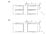
- Example 1 it was evaluated whether or not Example 1 can expect a noise shielding effect as compared with the prior art. That is, as shown in FIG. 11, a case (FIG. 11 (a )) And the vertical linear elements in the third area C (center part) in the upper area 10b are deleted, and the horizontal linear elements are connected to the bus bars 22 and 23 of the defogger 20 by connecting wires.
- the case corresponding to the noise shielding pattern (FIG. 11 (b)) and the case where the vertical linear element at the center portion in the upper area 10c is deleted and the connection points with both ends of the heat wires (bus bars 22, 23) are opened ( FIG.
- the noise reduction amount of evaluation 1 is 12.7 [dB]
- the noise reduction amount of evaluation 2 is 10.5 [dB]
- the noise reduction amount of evaluation 3 is 16.3 [dB]. Yes. Therefore, the case (FIG. 11 (c)) in which the connecting line between the horizontal line 21 of the defogger 20 and the noise shielding pattern is deleted and the vertical linear element in the center part is deleted is the most of the three cases. High noise reduction effect was obtained. At this time, the vertical linear element at the center may be installed.
- the vehicle window glass 1 is divided into the first area A, the second area B, and the third area C sandwiching the first area A and the second area B on the left and right.
- the noise shielding patterns # 1 to # 6 including at least two horizontal linear elements 1a (2a) and 1b (2b) are arranged in the first area A and the second area B, respectively.
- the noise shielding pattern is electrically insulated from the conductor including the vehicle. For this reason, the transmission of radio waves in the vicinity of the third area is suppressed, and therefore it is possible to prevent noise oscillated from the passenger compartment from being radiated in the center direction of the roof.
- the noise shielding effect is better than the case where the case where the noise shielding patterns # 1 to # 6 and the conductor such as the heat wire of the vehicle roof or the defogger 20 are separated by the connecting wire is connected. I found it expensive.
- the upper area 10 of the defogger 20 includes the first area A, the second area B, and the first area A and the second area B sandwiched between the left and right.
- the noise shielding patterns # 1 to # 6 are formed in the first area A and the second area B, respectively. Therefore, it is possible to prevent radio waves from being emitted toward the center of the vehicle roof.
- the noise shielding patterns # 1 to # 6 formed in each of the first area A and the second area B are provided with at least two horizontal lines having a size of approximately 1 ⁇ 4 wavelength.
- the amount of noise reduction increases.
- the element length of the horizontal linear elements 1a (2a) and 1b (2b) it depends on the installation position of the vertical linear element 1c (2c). It was found that the noise shielding effect of the received radio wave of 98 [MHz] is great.
- the noise shielding pattern # 7 includes at least two horizontal linear elements 1x and 1y extending in the horizontal direction and having element lengths of approximately 1 ⁇ 2 wavelength, and the horizontal linear elements 1x and 1y.
- the noise shielding pattern # 7 is disposed separately from a conductor such as a vehicle roof or a defogger heat ray. For this reason, it is possible to prevent noise oscillated from the passenger compartment from being emitted to the roof of the vehicle.
- the noise reduction amount is slightly inferior to the example in which the noise shielding pattern is arranged across the third area C, but the noise shielding effect almost equivalent to the prior art can be obtained. all right.
- the noise shielding patterns # 8 and # 9 according to the first embodiment have the second vertical linear element 1v disposed in the approximate center of the third area C and in parallel with the first vertical linear element 1c (2c). Is formed. According to this example, according to the evaluation by the inventors, it was found that a noise reduction amount having a large improvement effect can be obtained depending on the element lengths of the horizontal line elements 1a (2a) and 1b (2b).
- the heat rays (horizontal line elements) of the defogger 20 are arranged from the upper end to the lower end of the window glass 1, Is about 50 mm and is narrow.
- 13 (21a to 21m) heat rays having a length of 1190 mm are arranged at a pitch of 30 mm on an opening surface of 1230 mm ⁇ 460 mm.
- the bus bars 22 and 23 have a width of 10 mm.
- the noise shielding patterns # 1 to # 6 described in the first embodiment have vertical antenna elements that connect the horizontal antenna elements, and require an upper blank area of at least about 100 [mm]. Therefore, it is difficult to arrange the noise shielding patterns # 1 to # 6 shown in the first embodiment on the rear glass of the minivan or SUV.
- the vehicle window glass 1 has two noise shielding patterns # 1 shown in the first embodiment (FIG. 2) arranged in the upper and lower sides in the defogger 20.
- the noise shielding pattern # 10 is formed.
- the horizontal linear elements 1a and 2a forming the first set of noise shielding pattern # 10 are arranged so as not to overlap the hot wire horizontal filament 21a located at the uppermost stage of the defogger 20, and the horizontal linear elements 1b and 2b are It is arranged between the hot wire horizontal filaments 21f and 21g at a substantially intermediate position of the defogger 20.
- the horizontal linear elements 1a ′ and 2a ′ forming the second set of noise shielding pattern # 10 are disposed between the hot-wire horizontal filaments 21g and 21h at a substantially intermediate position of the defogger 20, and the horizontal linear element 1b ′. And 2b ′ are disposed below the horizontal hot wire 21m located at the bottom of the defogger 20.
- the noise shielding pattern # 10 includes two horizontal linear elements 1a and 1b having a size of approximately 1 ⁇ 4 wavelength in the first area A. Two sets of the vertical linear elements 1c that connect the horizontal linear elements 1a and 1b at one end thereof (the right front end portion) are arranged. Also, in the second area B, two horizontal linear elements 2a, 2b having a size of approximately 1 ⁇ 4 wavelength and the horizontal linear elements 2a, 2b are connected at one end (toward the left tip). Two sets of vertical linear elements 2c are arranged.
- the noise shielding pattern # 11 is formed by arranging two sets of the noise shielding pattern # 2 shown in the first embodiment (FIG. 3) in the defogger 20.
- the vertical linear element 1c is not positioned at one end of the horizontal linear elements 1a and 1b, but on the line where the horizontal linear elements 1a and 1b extend substantially parallel to the hot wire horizontal filaments 21a to 21m of the defogger 20.
- the vertical linear element 2c is connected not on one end of the horizontal linear elements 2a and 2b but on a line in the middle of the horizontal linear elements 2a and 2b extending substantially parallel to the hot wire horizontal filaments 21a to 21m of the defogger 20.
- the length of the horizontal linear elements 1a and 1b is approximately 1 ⁇ 4 wavelength when the horizontal linear elements 2a and 2b are long from the point where the horizontal linear elements 1a and 1b intersect with each other. Set to minutes.
- the noise shielding pattern # 12 is formed by arranging two pairs of the noise shielding pattern # 3 shown in the first embodiment (FIG. 4) in the defogger 20.
- Noise shielding pattern # 12 is obtained by adding vertical linear elements 1d and 2d to noise shielding pattern # 10.
- the vertical linear element 1d is arranged in parallel with the vertical linear element 1c
- the vertical linear element 2d is arranged in parallel with the vertical linear element 2c.
- the element length x of the horizontal linear elements extending in the edge direction from the position where the vertical linear elements 1c and 2c are connected is approximately 1 ⁇ 4 wavelength.
- the noise shielding pattern # 13 is formed by arranging two sets of the noise shielding pattern # 9 shown in the first embodiment (FIG. 10) in the upper and lower sides of the defogger 20.
- the vertical linear elements 1v formed in the third area C are arranged in parallel to the vertical linear elements 1c and 2c at a predetermined interval.
- FIG. 13 (e) shows that the connecting position of the vertical linear element 1c (2c) and the horizontal linear element 1a, 2a (1b, 2b) is not the tip of the vertical linear element 1c (2c) but the vertical linear element 1d. (2d) extends from the tip of the horizontal line elements 1a, 2a (1b, 2b) in the vertical direction, and here is the noise shielding pattern # 15.
- the element length x of the horizontal linear elements extending in the edge direction from the position where the vertical linear elements 1c and 2c are connected is approximately 1 ⁇ 4 wavelength.
- the noise shielding pattern # 15 is formed by arranging two sets of the noise shielding pattern # 4 shown in the first embodiment (FIG. 5) in the defogger 20.
- Noise shielding pattern # 15 is obtained by adding horizontal linear elements 1e and 2e to noise shielding pattern # 10 shown in FIG.
- the horizontal linear element 1e is arranged so as to extend from the approximate center position of the vertical linear element 1c in parallel with the horizontal linear elements 1a and 1b toward the outside of the window glass 1.
- the horizontal linear element 2e is arranged so as to extend from the substantially central position of the vertical linear element 2c in parallel with the horizontal linear elements 2a and 2b toward the outside of the window glass 1.
- the noise shielding pattern # 16 is formed by arranging two sets of the noise shielding pattern # 5 shown in the first embodiment (FIG. 6) in the upper and lower sides of the defogger 20.
- Noise shielding pattern # 16 is obtained by adding horizontal linear elements 1e and 2e to noise shielding pattern # 11 shown in FIG.
- the horizontal linear element 1e is arranged so as to cross the approximate center position of the vertical linear element 1c and to extend in the outward direction of the window glass in parallel with the horizontal linear elements 1a and 1b.
- the horizontal linear element 2e is arranged so as to extend toward the substantially central direction of the vertical linear element 2c.
- the noise shielding pattern # 17 is formed by arranging two sets of the noise shielding pattern # 6 shown in the first embodiment (FIG. 7) in the upper and lower sides of the defogger 20.
- the noise shielding pattern # 17 is formed by superposing the noise shielding pattern # 12 of FIG. 13C and the noise shielding pattern # 15 of FIG.
- the noise shielding pattern # 19 is formed by arranging two sets of the noise shielding pattern # 9 shown in the first embodiment (FIG. 10) in the upper and lower sides.
- the noise shielding pattern # 19 is formed by superimposing the noise shielding pattern # 13 in FIG. 13D and the noise shielding pattern # 15 in FIG.
- the noise shielding pattern # 19 is formed by arranging two sets of the noise shielding pattern # 7 shown in the first embodiment (FIG. 8) in the defogger 20.
- the noise shielding pattern # 19 is the same as when the interval d of the noise shielding pattern # 10 is zero.
- d means a distance [mm] from the center position of the third area C to the vertical linear elements 1c and 2c.
- two horizontal linear elements 1x and 1y are arranged substantially in parallel with the plurality of hot-wire horizontal filaments 21a to 21m of the defogger 20, and a substantially central point of the horizontal linear elements 1x and 1y is vertical. They are connected by a linear element 1c.
- This noise shielding pattern # 19 is also formed so as to be electrically separated from conductors such as the roof of the vehicle and the defogger 20 similarly to the noise shielding patterns # 10 to # 18 described above.
- the noise shielding pattern # 20 is formed by arranging two sets of the noise shielding pattern # 15 shown in FIG. 14A with the interval d set to 0 in the defogger 20. .
- a vertical linear element 1c is arranged at a substantially central portion of the defogger 20, and the horizontal linear elements 1x and 1y are arranged in the edge direction between the upper and lower ends of the vertical linear element 1c. It is a thing.
- the element lengths of the horizontal linear elements 1x and 1y are set to approximately 1 ⁇ 4 wavelength as in the first embodiment.
- the horizontal linear elements 1a, 2a, 1b, 2b (1a ′, 2a ′, 1b ′, 2b ′) forming the noise shielding pattern straddle between the hot wire horizontal filaments 21a to 21m of the defogger 20.
- a vehicle having no blank area above the defogger such as a minivan or an SUV vehicle, can block noise oscillated from inside the vehicle. The basis for this will be described below based on the evaluation results.
- Example 2 the results of the noise performance evaluation of the vehicle window glass 1 according to Example 2 will be described.
- circular polarization was used as the oscillation antenna, and the electric field strength near the roof pole antenna was measured.
- the evaluation frequency of the electric field strength in the vicinity of the oscillation antenna and the pole antenna was 98 MHz, which is the center frequency from the overseas frequency 88 [MHz] to 108 [MHz].
- the distance from the center position of the third area C to the vertical linear elements 1c, 2c is d [mm]
- the interval between the upper and lower horizontal linear elements 1a, 2a, 1b, 2b (vertical linear element length). ) Is expressed as y [mm]
- the line lengths of the horizontal linear elements 1a, 2a, 1b, and 2b are expressed as x [mm]. Since x is about 1/4 wavelength, the 1/4 wavelength of 98 [MHz] is about 450 [mm] when the shortening rate is 60 [%].
- the interval between the hot wire horizontal filaments 21a to 21m of the defogger 20 is 30 [mm]
- the interval from the uppermost hot wire horizontal filament 21a to the upper edge of the window glass is 50 [mm]
- the lowest hot wire horizontal filament was set to 50 [mm].
- the element length x of the horizontal linear elements 1a, 2a, 1b, 2b is fixed at 410 [mm]
- the element length y of the vertical linear elements 1c, 2c is fixed at 180 [mm]
- the distance d [mm] ] was evaluated for the amount of noise reduction. The results are as shown in Table 11 below.
- the noise shielding effect of 98 [MHz] when the interval d is 0 is 8.8 [dB], which is slightly inferior to the others. Increasing the value of d increases the noise shielding effect, and becomes almost flat when d exceeds 100.
- the element length x of the horizontal linear elements 1a, 2a, 1b, 2b (1a ′, 2a ′, 1b ′, 2b ′) is fixed to 365 while the distance d is fixed at 100 [mm] and the total element length is fixed.
- the noise reduction amount was also evaluated when the line length y of the vertical linear elements 1c and 2c (1c ′, 2c ′) was changed within the range of 60 to 270 [mm]. The results are as shown in Table 12 below.
- the distance d is fixed
- the element lengths of the horizontal linear elements 1a, 2a, 1b, 2b are fixed.
- the noise shielding amount when x was changed was also evaluated. The results are as shown in Table 13 below.
- the distance from the center position of the third area C to the vertical linear element 1c (2c) is fixed at 100 [mm] or 50 [mm], and the vertical linear element 1c (2c)
- the element length y (the distance between the upper and lower horizontal linear elements 1a, 2a (1b, 2b)) is fixed at 180 [mm], and the horizontal linear elements 1a, 2a, 1b in the edge direction from the vertical linear element 1c (2c) are fixed.
- Noise shielding amount when the element length x of 2b is fixed at x 410 [mm] and the distance d [mm] from the center position to the vertical linear elements 1c and 2c is changed (50 to 175 [mm]) evaluated.
- Table 15 The results are as shown in Table 15 below.
- the horizontal linear elements 1a, 2a, 1b, and 2b are provided with 1 ⁇ 4 wavelength from the vertical linear elements 1c and 2c, and the vertical linear elements 1c and 2c are horizontal lines. It can be seen that there is no influence on the noise shielding effect even if it is not connected to the tip position of the element 1a, 2a, 1b, 2b. It was also found that the noise shielding effect can be maintained even when the distance d is increased.
- the noise shielding pattern # 12 is obtained by adding vertical linear elements 1d and 2d to the noise shielding pattern # 10.
- the distance d from the center position of the third area C to the vertical linear element 1c (2c) is fixed at 100 [mm], and the added vertical linear elements 1d and 2d are set closer to the central position.
- the results are as shown in Table 17 below.
- the element length x of the horizontal linear elements 1a, 2a, 1b, and 2b is provided for approximately 1 ⁇ 4 wavelength (410, 450 [mm]) from the vertical linear elements 1c and 2c. From this, it can be seen that even if a plurality of vertical linear elements are installed, the noise shielding effect is not affected.
- the noise shielding pattern # 13 is obtained by adding vertical linear elements 1v and 1v 'at a substantially central position of the noise shielding pattern # 10.
- the noise shielding pattern # 14 shown here has a pattern in which the vertical linear elements 1c, 2c are extended above and below the horizontal linear elements 1a, 2a, 1b, 2b (1a ', 2a', 1b ', 2b').
- the noise shielding amount was evaluated. The results are as shown in Table 19 below.
- the noise shielding amount is 13.0 [dB] which is preferable, and therefore the vertical linear elements 1c and 2c are replaced with the horizontal linear elements 1a, 2a, 1b and 2b (1a ', 2a', 1b ', It has been found that the noise shielding effect is not affected even if extended up and down 2b ′).
- the noise shielding pattern # 15 shown here is a pattern in which horizontal linear elements 1e and 2e are added between the horizontal linear elements 1a and 1b and 2a and 2b, respectively.
- the element length y (vertical horizontal linear elements 1a, 2a) of the vertical linear element 1c (2c) is fixed.
- a suitable noise shielding amount can be obtained when the element length of the horizontal linear elements 1a and 2a (1b and 2b) is in the vicinity of 1 ⁇ 4 wavelength. Therefore, the vertical linear elements 1c and 1c ′ are attached to the window glass. It has been found that a suitable noise shielding effect can be obtained even when integrated at approximately the center of 1.
- the inventors made various noise shielding patterns other than the above and tried to evaluate the noise shielding effect.
- the evaluation results for each manufactured noise shielding pattern will be described below.
- FIG. 16 shows an example in which the noise shielding pattern # 10 is changed from a U-shape to a square shape with vertical linear elements added in the horizontal edge direction.
- the distance d from the substantially central portion to the vertical linear element is 100 [mm]
- the vertical line The amount of noise shielding was evaluated when the element length x of the horizontal linear element extending in the edge direction from the linear element was set to 1/4 wavelength (410 [mm]). The results are as shown in Table 22 below.
- FIG. 17 shows a noise shielding pattern in which the vertical linear element of the noise shielding pattern # 10 is deleted.
- the results of evaluation under the same conditions as the above noise shielding pattern are as shown in Table 23 below.
- the distance d is 100 [mm]
- the element length x of the horizontal linear elements extending in the edge direction from the vertical linear elements is approximately 1 /.
- the amount of noise shielding in the case of 4 wavelengths (410 [mm]) was evaluated. The results are as shown in Table 23 below.
- FIG. 18 shows a noise shielding pattern in which the tip of the vertical linear element of the noise shielding pattern # 10 is not connected to the horizontal linear element.
- Table 24 The results of evaluation under the same conditions as the above noise shielding pattern are as shown in Table 24 below.
- FIG. 19 shows a noise shielding pattern in the case where the noise shielding pattern # 10 is one set on the upper side.
- the results of evaluation under the same conditions as the above noise shielding pattern are as shown in Table 25 below.
- the noise shielding pattern # 10 which is the upper set, has a noise shielding amount of 1.1 [dB] and has almost no noise shielding effect.
- the hot wire vertical line 21v in FIG. 20 (a) is the hot wire horizontal line 21g to the horizontal line element of the noise shielding pattern # 10 arranged among the hot wire horizontal lines 21a to 21m constituting the defogger 20. 21m is connected, and the hot wire vertical line 21v in FIG. 20B intersects all of the hot wire horizontal lines 21a to 21m.
- Table 26 The results of evaluation under the same conditions as the above noise shielding pattern are as shown in Table 26 below.
- the horizontal linear elements that form the noise shielding pattern are formed between the hot wire horizontal lines 21a to 21m of the defogger 20, for example, a minivan, an SUV car, etc. Even a vehicle without a blank area above the defogger can block noise oscillated from inside the vehicle. At this time, it has been found that the noise shielding effect is large without depending on the installation position of the vertical linear element by setting the horizontal linear element forming the noise shielding pattern to an element length of about 1 ⁇ 4 wavelength. Also, a suitable noise shielding effect can be obtained by setting the element length of the vertical linear element forming the noise shielding pattern from about 1/32 wavelength to about 1/8 wavelength.
- a noise shielding pattern is provided in the upper blank area of the defogger 20, and in the second embodiment, the noise shielding effect is provided by coexisting with the defogger 10 so as not to overlap the horizontal line of heat rays. Got.
- the defogger 20 obtains a noise shielding effect even if a noise shielding pattern is directly disposed on the glass surface.
- the window glass 1 of a vehicle according to the third embodiment is a pattern in which the hot wire horizontal stripes of the defogger 20 are deleted from the noise shielding pattern # 10, which will be described below.
- the window glass 1 shown in FIGS. 21A and 21B is an example in which all the heat ray horizontal lines are deleted, and the window glass 1 shown in FIG. This is an example in which a part is deleted.
- the noise shielding amount changes in the range of 12.2 to 15.7 [dB], the number of the hot wire horizontal filaments is changed, or even if there is no hot wire horizontal filament, It can be seen that a noise shielding effect can be obtained by arranging two sets of noise shielding patterns # 10. Further, even when the distance between the heat ray horizontal line and the body edge at the top of the window glass 1 is large, a considerable amount of noise shielding can be obtained by disposing the noise shielding pattern # 10 from the top, and the noise shielding. It turns out that an effect is acquired.
- FIG. 23 is a pattern in which all the heat ray horizontal stripes of the noise shielding pattern # 10 are deleted.
- the noise shielding pattern # 10 has three stages of upper, lower, and middle, and the window glass 1 (vehicle opening) is expanded.
- An example is shown.
- the distance b from the upper edge of the body edge is fixed to 35 [mm]
- the element length x of the horizontal linear element in the edge direction from the vertical linear element is changed (380 to 430 [mm]).
- the amount was evaluated. The results are as shown in Table 28 below.
- noise shielding pattern # 10 is arranged at the top and bottom even when there is no horizontal hot wire, thereby shielding noise. It turns out that an effect is acquired.
- FIG. 24 shows a case where one set of the noise shielding pattern # 10 is provided on the upper part of the horizontal hot wire forming the defogger 20 (FIG. 24A) and a case where the noise shielding pattern # 10 is provided across the hot wire vertical line (FIG. 24). 24 (b)).
- Table 29 shows a case where one set of the noise shielding pattern # 10 is provided on the upper part of the horizontal hot wire forming the defogger 20 (FIG. 24A) and a case where the noise shielding pattern # 10 is provided across the hot wire vertical line (FI
- the noise shielding amount is 0.7 [dB] in the case of FIG. 24 (a), and 1.0 [dB] in the case of FIG. 24 (b).
- 25 (a) and 25 (b) are noise shielding patterns obtained by adding, to the noise shielding patterns shown in FIGS. 24 (a) and 24 (b), a hot wire vertical line connecting the centers of the horizontal hot wire lines.
- Table 30 The results of evaluation under the same conditions as above are shown in Table 30 below.
- 26 (a) and 26 (b) show a case in which three sets of noise shielding patterns # 10 are arranged and the distance b from the vehicle body is changed.
- Table 31 below shows the evaluation results when the distance b from the vehicle body is changed in the range of 6.7 to 15.7 [mm] under the same conditions as described above.
- FIG. 27 shows a case where the noise shielding pattern # 10 is arranged on the three sets of window glass 1 and there is no heat ray horizontal stripe element, and the evaluation results when the distance b from the vehicle body is changed under the same conditions as described above are as follows. Table 32 shows.
- the noise shielding effect is increased by arranging the noise shielding pattern # 10 above and below, but the noise shielding effect is weakened when the distance b from the vehicle body is widened. I understand.
- FIG. 28 shows a case where the noise shielding pattern # 10 is disposed on the two sets of window glass 1 and there is no heat ray horizontal stripe element, and the evaluation results when the distance b from the vehicle body is changed under the same conditions as described above are as follows. Table 33 shows.
- the noise shielding effect is increased by arranging the noise shielding pattern # 10 above and below, but when the distance b from the vehicle body is widened, the noise shielding effect is enhanced. It turns out that it becomes weak.
- FIG. 29 shows a case where only one set of noise shielding pattern # 10 is arranged on the window glass 1 and there is no heat ray horizontal stripe element, and the evaluation result when the distance b from the vehicle body is changed under the same conditions as above. It is shown in Table 34 below.
- FIG. 30 (a) and 30 (b) are cases where the noise shielding pattern # 10 is disposed on the entire surface of the window glass 1 without the thermal horizontal line
- FIG. 30 (a) shows two sets of noise shielding patterns # 10.
- 30 (b) shows an example in which one set of noise shielding pattern # 10 is arranged.
- two or more sets of noise shielding patterns # 10 are provided on the window glass 1 even when the number of the hot wire horizontal filaments of the defogger 20 is reduced or there is no hot wire horizontal filament.
- a noise shielding effect can be obtained.
- the horizontal linear elements that form the noise shielding pattern have an element length corresponding to approximately 1 ⁇ 4 wavelength, so that the noise does not depend on the installation position of the vertical linear elements.
- a suitable noise shielding effect can be obtained by setting the element length of the vertical linear element forming the noise shielding pattern from about 1/32 wavelength to about 1/8 wavelength. .
- FIGS. 31A and 31B show the electric field distribution on the front and rear surfaces of the window glass 1 when the noise shielding pattern is not installed
- FIGS. 32A and 32B show the front of the window glass 1 when the noise shielding pattern is installed
- FIG. 6 is a diagram showing both the electric field distribution on the back and the rear surface in shades. A dark portion indicates a strong distribution, and a thin portion indicates a weak distribution.
- FIG. 31 and FIG. 32 it can be seen that a strong electric field against the noise shielding pattern can be confirmed in FIG. 32 (a), and the rear electric field distribution is shielded in FIG. 32 (b). Therefore, according to the window glass 1 of the vehicle of the present invention, noise can be further reduced in an environment where electromagnetic waves generated by the operation of electrical components in the vehicle interior are given to the pole antenna as noise.
- SYMBOLS 1 Window glass, 1a, 1b, 1e, 1x, 1y, 2a, 2b, 2e ... Horizontal linear element, 1c, 1d, 1v, 1z, 2c, 2d ... Vertical linear element, 10 ... Upper area, A ... First 1 area, B ... second area, C ... third area, 20 ... defogger, 21a to 21m ... hot wire horizontal stripe, 21v ... hot wire vertical stripe, 22, 23 ... bus bar.
Abstract
車室内の電装部品の作動により発生する電磁波がノイズとしてルーフアンテナに与えることを低減する車両用窓ガラスが開示される。車両の窓ガラス(1)に形成されたデフォッガ(20)の上部エリア(10)には、デフォッガ(20)の水平線条(21)と略平行に配設された少なくとも2本の水平線状素子(1a,2a,1b,2b)からなるノイズ遮蔽パターン(#1~#9)が、ルーフやデフォッガ20の熱線とは電気的に絶縁して配設される。
Description
本発明は、車両のルーフ後方にポールアンテナを有し、後部窓ガラスに複数の水平線状からなる熱線とその両端を接続するバスバーとからなるデフォッガが配設された、車両の窓ガラスに関する。
車両用のAM/FM用ラジオアンテナとして、車両のルーフ後方に取り付けられる棒状のルーフアンテナ(以下、ポールアンテナという)や、後方窓ガラス(リアガラス)面上にプリントされたフィルムアンテナ等が知られている。これらのAM/FM用ラジオアンテナには、車室内の電装部品から発せられるノイズが伝播することが多い。このため、従来、リアガラス面上に形成されるデフォッガの上部エリアにノイズ遮蔽パターンを設置した車両の窓ガラスが提案されている(例えば、特許文献1参照。)。
図33及び図34は、特許文献1に開示されたノイズ遮蔽パターンを示している。図33に示されるように、車両100のルーフ後方にはポールアンテナ60が取り付けられている。ノイズ遮蔽パターン51は、後部窓ガラス50に形成されるデフォッガ52の上部エリアに形成されている。ノイズ遮蔽パターン51は、車室内の電装部品の作動によって発生するノイズを遮蔽し、ポールアンテナ60にノイズを伝達させないようにしている。
ノイズ遮蔽パターン51は、図34に示されるように、車室内の電装部品の作動により発生する電磁波がノイズとしてポールアンテナ60に与える環境下にあって、複数の水平線条からなる熱線521とその両端を接続するバスバー522,523とからなるデフォッガ52の上部エリアに形成される。
ノイズ遮蔽パターン51は、デフォッガ52の上部余白エリアに、少なくとも3本の水平線条516と、少なくとも1本の垂直線条517とを互いに交差させ、左右対称パターンとした線条パターンで形成される。このノイズ遮蔽パターン51とデフォッガ52とを、中央部と、その左右対称となる位置に3本の垂直線条517で接続し、電装部品による電磁波ノイズをこのノイズ遮蔽パターン51で遮蔽し、ポールアンテナ60にノイズを伝達させないようにしている。
特許文献1に開示された技術によれば、リアガラスに設けられたデフォッガの上部エリアに、左右対称形状のノイズ遮蔽パターン51を設け、このノイズ遮蔽パターン51を少なくとも3本の接続線条517により左右対称位置でデフォッガ52に接続したことで、ポールアンテナ60に伝達されるノイズを一定量低減することができる。
しかしながら、依然として車室内から発振されたノイズがルーフに設置されたポールアンテナに誘起され、このため、ポールアンテナがノイズを受信してしまい、上述したノイズ遮蔽パターン51によっても十分な量のノイズ低減効果はない。今後、一層エレクトロニクス化が進み、数多くの電装部品が使用されつつある状況の中で、十分なノイズ低減効果が得られていないのが実情である。
本発明は、車室内の電装部品の作動により発生する電磁波がノイズとしてポールアンテナに与える環境下にあって、一層ノイズ低減を行うことができる、車両窓ガラスを提供することを課題とする。
請求項1に係る発明によれば、車両にルーフアンテナが取り付けられており、前記車両のガラス面上にノイズ遮蔽パターンが配設された車両用窓ガラスであって、前記ガラス面は、第1のエリアと、第2のエリアと、前記第1のエリアと前記第2のエリアによって左右に挟まれる第3のエリアとを含み、前記ノイズ遮蔽パターンは、前記第1のエリアと前記第2のエリアに、少なくとも2本の水平線状素子と、前記水平線状素子のそれぞれを接続する1本以上の第1の垂直線状素子とからなり、前記ノイズ遮蔽パターンの各々は、前記車両を含む導体とは電気的に絶縁されている車両の窓ガラスが提供される。
請求項2に係る発明によれば、好ましくは、前記第1の垂直線状素子は、前記水平線状素子の前記第3のエリアに近い方の先端と交わる。
請求項3に係る発明によれば、好ましくは、前記第3のエリアの略中央に、前記第1のエリアにおける前記第1の垂直線状素子と略平行に配設された第2の垂直線状素子が配設されている。
請求項4に係る発明によれば、好ましくは、前記ノイズ遮蔽パターンは、前記窓ガラス面上に形成されたデフォッガの上方に位置する上部エリアに形成される。
請求項5に係る発明によれば、好ましくは、前記デフォッガの複数の熱線水平線条の略中央に前記熱線水平線条のそれぞれを接続する熱線垂直線条が配置されている。
請求項6に係る発明によれば、好ましくは、前記ノイズ遮蔽パターンは、前記ガラス面上に形成されたデフォッガが有する複数の熱線水平線条の間に、少なくとも一部の前記水平線状素子が跨って形成される。
請求項7に係る発明によれば、好ましくは、前記ノイズ遮蔽パターンを形成する前記水平線状素子の素子長は、前記垂直線状素子が前水平線状素子に交わる点を基点に長い方の部位がいずれも略1/4波長分に設定されている。
請求項8に係る発明によれば、好ましくは、前記ノイズ遮蔽パターンを形成する前記垂直線状素子の素子長は、略1/32波長から略1/8波長分に設定されている。
請求項9に係る発明によれば、車両にルーフアンテナが取り付けられており、前記車両のガラス面上にノイズ遮蔽パターンが配設された車両用窓ガラスであって、前記ノイズ遮蔽パターンは、水平方向に延びる少なくとも2本の水平線状素子と、前記水平線状素子の各々の略中央を接続する1本以上の垂直線状素子と、からなり、前記ノイズ遮蔽パターンは、前記車両を含む導体と電気的に絶縁されている車両の窓ガラスが提供される。
請求項10に係る発明によれば、好ましくは、前記水平線状素子の素子長は、前記垂直線状素子が前記水平線状素子に交わる点を基点に長い方の部位がいずれも略1/4波長分に設定されている。
請求項1に係る発明によれば、車両の窓ガラスの上部エリアを、第1のエリアと、第2のエリアと、第1のエリアと第2のエリアによって左右に挟まれる第3のエリアとに区分し、第1のエリアと第2のエリアに、少なくとも2本の水平線状素子と、この水平線状素子のそれぞれを接続する1本以上の第1の垂直線状素子とからなるノイズ遮蔽パターンをそれぞれ配設し、それぞれのノイズ遮蔽パターンは、車両を含む導体と電気的に絶縁されている。このため、第3エリアの近傍の電波の透過が抑制され、したがって、車室内から発振されるノイズがルーフのセンター方向に放射されるのを防ぐことができる。
請求項2に係る発明によれば、第1の垂直線状素子は、水平線状素子の第3のエリアに近い方の先端と交わる。垂直線状素子を水平線状素子の中央よりの先端に接続するケースが、水平線状素子の逆方向の先端位置、あるいは略中央に接続するケースに比べてノイズ遮蔽効果が大きい。
請求項3に係る発明によれば、第3のエリアの略中央に、第1のエリアにおける第1の垂直線状素子と略平行に配設された第2の垂直線状素子が配設される。第3のエリアの略中央に第2の垂直線状素子を配設しても、左右それぞれの水平線状素子の素子長を略1/4波長とすることによりノイズ遮蔽効果に影響の無いアンテナパターンが得られる。
請求項4に係る発明によれば、ノイズ遮蔽パターンをデフォッガの上部エリアに形成することとした。このため、車室内の電装部品の作動により発生する電磁波がノイズとしてポールアンテナに与える環境下にあって、一層ノイズ低減を行うことができる。
請求項5に係る発明によれば、デフォッガの熱線水平線条の略中央に熱線垂直線条を配置することで、ノイズ遮蔽効果を増すことができる。
請求項6に係る発明によれば、ノイズ遮蔽パターンを形成する水平線状素子がデフォッガの熱線水平線条間に跨って形成されることで、例えば、ミニバン(Station Wagonを含む)やSUV(Sport Utility Vehicle)等、デフォッガの上部に空白領域が無い車両であっても車内から発振されるノイズを遮蔽することができる。
請求項7に係る発明によれば、水平線状素子の素子長は、略1/4波長分に設定される。水平線状素子を略1/4波長分の素子長にすることで、垂直線状素子の設置位置に依存することなくノイズの遮蔽効果が大きい。
請求項8に係る発明によれば、発明者らの評価では、ノイズ遮蔽パターンを形成する垂直線状素子の素子長が1/10波長分の長さをピークに悪化することから、垂直線状素子の素子長を、略1/32波長から略1/8波長分に設定することで好適なノイズ遮蔽効果が得られることがわかった。
請求項9に係る発明によれば、ノイズ遮蔽パターンは、水平方向に延びる少なくとも2本の、略1/2波長分の素子長を有する水平線状素子と、それぞれの水平線状素子の略中央を接続する1本以上の垂直線状素子からなり、このノイズ遮蔽パターンをルーフ等の導体とは分離して配設した。このため、車室内から発振されるノイズが車両のルーフに放射されるのを防ぐことができる。第3のエリアを挟んでノイズ遮蔽パターンを配設する例に比べてノイズ低減量は若干劣るが、先行技術とほぼ同等のノイズ遮蔽効果が得られる。
請求項10に係る発明によれば、水平線状素子の素子長について、垂直線状素子が水平線状素子に交わる点を基点に長い方の部位をいずれも略1/4波長分に設定した。水平線状素子の長い方の部位を略1/4波長分の素子長にすることでノイズの遮蔽効果が大きい。
以下、本発明の好ましい実施の形態例について、実施例毎、添付した図面に基づいて説明する。
実施例1による車両の窓ガラス1は、例えば、車両のリアウインドウに取り付けられる。図1に示されるように、リアウインドウ(車両用窓ガラス1)には、デフォッガ20が配置されており、デフォッガ20の上部エリア10にはAM/FM用ラジオアンテナ等がプリントされるケースが多い。但し、車両のルーフ後方に設けられるポールアンテナをAM/FM用ラジオアンテナとして用いる場合、デフォッガ20の上部エリア10は余白となるケースがほとんどである。そこで、実施例1による車両の窓ガラス1では、この上部エリアに、以下に説明するノイズ遮蔽パターンをプリントする。
図1に示されるように、この上部エリア10は、第1のエリアAと、第2のエリアBと、第1のエリアAと第2のエリアBによって左右に挟まれる第3のエリアCとからなる。第1のエリアAと第2のエリアBのそれぞれに、以下に説明するノイズ遮蔽パターン#1~#6のいずれかが形成され、第3のエリアCはガラスのみで形成されるものとする。ノイズ遮蔽パターン#1~#6は、いずれも車両のルーフやデフォッガ20等の導体に対して電気的に分離(絶縁)され形成されている。
図2~図7に、第1のエリアAと第2のエリアBに配置されるノイズ遮蔽パターンの一例が示されている。図2~図7において、符号d,x,yで示されるサイズは、後述するノイズ低減効果の評価の際に使用されるパラメータであって詳細は後述するものとし、まずは、ノイズ遮蔽パターンの構成のみを説明する。
図2に示すノイズ遮蔽パターン#1は、デフォッガ20の上部エリア10において、第1のエリアAには、略1/4波長のサイズを有する2本の水平線状素子1a,1bと、水平線状素子1a,1bを、その一端(向かって右先端部)で接続する垂直線状素子1cとが配置される。また、第2のエリアBには、略1/4波長のサイズを有する2本の水平線状素子2a,2bと、この水平線状素子2a,2bを、その一端(向かって左先端部)で接続する垂直線状素子2cとが配置される。
図3に示すノイズ遮蔽パターン#2は、垂直線状素子1cを、水平線状素子1a,1bの一端ではなく、水平線状素子1a,1bがデフォッガ20の複数水平線条21からなる熱線と略平行に延びる途中の線上(p点)で接続している。垂直線状素子2cも同様に、水平線状素子2a,2bの一端ではなく、水平線状素子2a,2bがデフォッガ20の熱線と略平行に延びる途中の線上(q点)で接続している。このノイズ遮蔽パターン#2において、水平線状素子1a,1bの素子長は、水平線状素子2a,2bが水平線状素子1a,1bのそれぞれに交わる点を基点に長い方がいずれも略1/4波長分に設定される。
図4に示すノイズ遮蔽パターン#3は、図2に示すノイズ遮蔽パターン#1に、垂直線状素子1d,2dを付加したものである。垂直線状素子1dは、垂直線状素子1cと平行に、垂直線状素子2dは、垂直線状素子2cと平行に、それぞれ配置される。
図5に示すノイズ遮蔽パターン#4は、図2に示すノイズ遮蔽パターン#1に水平線状素子1e,2eを付加したものである。水平線状素子1eは、垂直線状素子1cの略中央位置から水平線状素子1a,1bと平行に、窓ガラス1の外側方向に向けて延びるよう配置されている。水平線状素子2eは、垂直線状素子2cの略中央位置から水平線状素子2a,2bと平行に、窓ガラス1の外側方向に向けて延びるよう配置されている。
図6に示すノイズ遮蔽パターン#5は、図3に示すノイズ遮蔽パターン#2に、水平線状素子1e,2eを付加したものである。水平線状素子1eは、垂直線状素子1cの略中央位置にクロスして水平線状素子1a,1bと平行に、窓ガラス1の外側方向に向かって延びるよう配置されている。水平線状素子2eは、垂直線状素子2cの略中央位置にクロスして水平線状素子2a,2bと平行に、窓ガス1の外側に向かって延びるよう配置されている。
図7に示すノイズ遮蔽パターン#6は、図4に示したノイズ遮蔽パターン#3と、図5に示したノイズ遮蔽パターン#4とを重ね合わせて形成したものである。
上記したノイズ遮蔽バターン#1(図2)~#6(図7)は、いずれも、第1のエリアAにノイズ遮蔽バターン#1~#6のいずれかをU字形状に配設し、第2のエリアBにノイズ遮蔽パターン#1~#6のいずれかをU字形状に配設することで、ガラスのみで形成される第3のエリアCを挟んで左右対称に形成されている。換言すれば、デフォッガ20の上部エリア10の略中央位置を基点に、所定の間隔(第3のエリアC)を空けて左右方向にそれぞれ延びる水平線状素子1a(2a),1b(2b),1e(2e)が少なくとも2本ずつ配設され、この少なくとも2本ずつ配設された水平線状素子1a(2a),1b(2b),1e(2e)を、先端又は途中位置でそれぞれ接続する垂直線状素子1c,1d(2c,2d)が配設されたノイズ遮蔽パターンである。
図8に示すノイズ遮蔽パターン#7は、デフォッガ20の上部エリア10に、デフォッガ20の複数の,熱線水平線条21からなる熱線と略平行に2本の水平線状素子1x,1yが配設され、これら水平線状素子1x,1yの略中央の点が垂直線状素子1zで接続されている。図8に示すノイズ遮蔽パターン#7も、上記したノイズ遮蔽パターン#1~#6と同様、車両のルーフ及びデフォッガ20等の導体と電気的に分離され形成されている。
図9に示すノイズ遮蔽パターン#8は、図2に示したノイズ遮蔽パターン#1を基本パターンとし、第3のエリアCの略中央に垂直線状素子1vが付加されたものである。
図10に示すノイズ遮蔽パターン#9は、図5に示したノイズ遮蔽パターン#4を基本パターンとし、第3のエリアCに形成される垂直線状素子1vが付加されたものである。この垂直線状素子1vは、垂直線状素子1c,2cに対して所定の間隔を空けて平行に配置される。
上記したノイズ遮蔽パターン#1~#9をデフォッガ20上部エリア10に配置することで、車室内から発振されるノイズが車両ルーフのセンター方向に放射するのを防ぐことができる。特に、日本国内では76[MHz]から90[MHz]の周波数で、海外では88[MHz]から108[MHz]の周波数帯でサービスされているFM用ラジオ周波数帯で、車室内から発振されたノイズが天井のポールアンテナに誘起され、ポールアンテナがノイズを受信してしまう環境にあっても、車両窓ガラス1に形成されたデフォッガ20の上部エリア10に設置されるノイズ遮蔽パターン#1~#9により、車内から発振されるノイズを遮断することができる。
また、デフォッガ20の上部エリア10の略中心位置から所定の間隔を空けて左(右)に複数の水平線状素子1a(2a),1b(2b)を設置し、それらを垂直線状素子1c(2c)で接続する。このときの水平線状素子長を、垂直線状素子1c(2c)の接続箇所から略1/4波長とすることで、デフォッガ20の複数の水平線条21からなる熱線上部の中央付近の電波の透過を抑えることができる。このため、ルーフのセンター方向への電波の放射を防ぐことが可能になる。これは、ノイズ遮蔽パターン#1~#9により、車室内から発振されるノイズが、ルーフのセンター方向に放射されるのを防ぐ効果があるためと考えられる。このことにより、充分なノイズ除去効果を実現出来る。
以下、実施例1による車両用窓ガラス1のノイズ性評価の結果を説明する。評価にあたり、EV(Electric Vehicle)車、HV(Hybrid Vehicle)車の場合、車両から発振されるノイズは、電波の偏波が不明であるため、発振用アンテナとして円偏波を用いた。また、ノイズ発振源は、車室内であるものとし、この場合、ノイズが車両のルーフからポールアンテナに誘起されることが考えられるため、ルーフのポールアンテナ付近の電界強度を測定することにより評価した。発振用のアンテナ及びポールアンテナ付近の電界強度の評価周波数は、海外用周波数88[MHz]から108[MHz]の中心周波数である98MHzとした。
車両窓ガラス1に形成されたデフォッガ20の上部エリア10に配設されるノイズ遮蔽パターン#1~#9のノイズ減少量を評価するにあたり、遮蔽パターンを持たない場合のノイズ減少量を0として図34に示す従来のノイズ遮蔽パターの評価を行った。ここでは、上下の水平線条516の間隔yを135[mm]、中央から垂直線条517までの間隔dを100[mm]でそれぞれ固定し、水平線条516の線長xを400[mm]~600[mm]に変更することにより、ノイズ減少量を測定した。結果は、以下の表1に示す通りである。

表1に示した結果によれば、9.0[dB]~10.0[dB]の範囲でノイズ遮蔽効果が確認され、好適な評価結果が得られた。なお、以降の説明では、評価結果について、ノイズ減少量が3[dB]未満の場合に「遮蔽効果無し」、3[dB]以上6[dB]未満の場合に「遮蔽効果有り」、6[dB]以上10[dB]未満の場合に「好適」、10[dB]以上を「更に好適」と定義することとし、いずれのノイズ遮蔽パターンについても、遮蔽パターンを持たない場合のノイズ減少量を0としてノイズ減少量の評価を行なった。
まず、図2に示したノイズ遮蔽パターン#1から説明する。図2では、第3のエリアCの中央位置から垂直線状素子1c,2cまでの間隔をd[mm]とし、上下の水平線状素子1a(2a),1b(2b)の間隔(垂直線状素子長)をy[mm]とし、水平線状素子1a(2a),1b(2b)の線長をx[mm]として説明する。ここでは、水平線状素子1a(2a),1b(2b)の線長x[mm]、垂直線状素子1c(2c)の線長y[mm]を固定とし、間隔d[mm]を変更した場合のノイズ低減量を評価した。結果は表2に示す通りである。

表2によれば、d=0[mm]の場合を除き、垂直線状素子1c(2c)の設置位置に依存することなくノイズ減少量が更に好適な約16[dB]以上あり、比較基準例に比べてノイズ遮蔽効果が大きいことがわかった。但し、左右の水平線状素子1aと2a,1bと2bが接続された、図8に示すノイズ遮蔽パターン#7の場合、98[MHz]でのノイズ減少量は遮蔽効果が若干劣ることがわかった。
次に、水平線状素子1a(2a),1b(2b)の線長x[mm]、間隔d[mm]を固定とし、垂直線状素子1c(2c)の線長y[mm]を変更した場合のノイズ低減量を評価した。その結果を表3に示す。

表3によれば、水平線状素子1a(2a),1b(2b)の線長x[mm]の間隔が広い程ノイズ減少量が大きいことがわかった。
次に、垂直線状素子1c(2c)の線長yを固定し、間隔dを50[mm]と100[mm]で2段階に変更し、水平線状素子1a(2a),1b(2b)の線長xを変更した場合のノイズ低減量を評価した。その結果を表4に示す。

表4によれば、水平線状素子長が長いほどノイズ遮蔽効果が高いということではなく、水平線状素子1a(2a),1b(2b)を、略1/4波長分の長さ(波長短縮率を0.6としたときに、x=400[mm]~450[mm])に設定すれば、98[MHz]の電波受信時のノイズ遮蔽効果が大きいことがわかった。
次に、図2に示すノイズ遮蔽パターン#1の垂直線状素子を削除した場合のモデルについて評価した。その結果を表5に示す。

表5によれば、垂直線状素子1c(2c)を有するノイズ遮蔽パターン#1の中で最もノイズ低減効果が高かったx=450[mm],y=135[mm],d=100[mm]のときに、ノイズ低減量が0[dB]である。従って、垂直線状素子1c(2c)は必要であり、それぞれによる水平線状素子1a(2a),1b(2b)との接続が必要であることがわかる。
次に、図3のノイズ遮蔽パターン#2の評価について説明する。ここでは、垂直線状素子1c(2c)の水平線状素子1a(2a),1b(2b)への接続位置(図3ではp点、q点)を変更することによる評価を試みた。すなわち、水平線状素子長x[mm]と、垂直線状素子長y[mm]と、水平線状素子1a(2a),1b(2b)の先端位置d[mm]とを固定とし、垂直線状素子1c(2c)の設置位置d1[mm]を変更することにより評価した。その結果を表6に示す。

表6によれば、垂直線状素子1c(2c)は水平線状素子1a(2a),1b(2b)の先端、あるいは先端寄りでノイズ低減効果がみられ、水平線状素子1a(2a),1b(2b)の略中央付近ではでノイズ低減効果がみられなかった。このことから、垂直線状素子1c(2c)は、必ずしも水平線状素子1a(2a),1b(2b)の先端に接続することを必須としないが、水平線素子長を略1/4波長分確保することが必要であることがわかった。
次に、図4に示すノイズ遮蔽パターン#3の評価について説明する。水平線状素子1a(2a),1b(2b)の先端位置d[mm]、及び垂直線状素子1c(2c),1d(2d)の接続位置d1[mm]を変更して評価を試みた。その結果を表7に示す。

表7によれば、複数の垂直線状素子1c(2c),1d(2d)を設置し、d1=100[mm]としたときにノイズ低減効果が確認された。その結果、垂直線状素子1c(2c),1d(2d)は複数本設置してもかまわないが、水平線長素子1a(2a),1b(2b)の素子長は、略1/4波長分確保する必要があることがわかった。
次に、図5に示すノイズ遮蔽パターン#4の評価について説明する。ここでは、垂直線状素子長y[mm]及び間隔d[mm]を固定し、水平線状素子1a(2a),1b(2b),1e(2e)の線長x[mm]を変更して評価を試みた。その結果を表8に示す。

表8によれば、水平線状素子長xが400[mm]~450[mm]のところでノイズ量削減の改善効果が確認された。従って、左右それぞれの水平線状素子長x[mm]は、略1/4波長に設定すべきであり、また、水平線状素子は、2本でなくても3本でも良いことがわかった。なお、水平線状素子1a(2a),1b(2b),1e(2e)の最上線と最下線の間隔は広いほど良い。
次に、図9に示すノイズ遮蔽パターンの評価について説明する。図9に示すノイズ遮蔽パターンは、デフォッガ20の上部エリア10中、第3のエリアCの略中央部に垂直線状素子1vを付加したものである。ここでは、この垂直線状素子1vの素子長y[mm]及び間隔d[mm]を固定し、水平線状素子1a(2a),1b(2b)の線長x[mm]を変更して評価を試みた。結果は以下の表9に示す通りである。

表9によれば、水平線状素子長xが400[mm]~450[mm]のところでノイズ量削減の改善効果が確認された。このため、左右それぞれの水平線状素子長は、略1/4波長に設定すべきであり、センターに垂直線状素子1vを設置してもかまわないことがわかる。
最後に、実施例1が先行技術と比較してノイズ遮蔽効果が見込めるか否かについて評価した。すなわち、図11に示されるように、上部エリア10a中の水平線状素子とデフォッガ20の複数の水平線条21からなる熱線両端(バスバー22,23)との接続箇所を開放したケース(図11(a))と、上部エリア10b中の第3のエリアC(センター部分)の垂直線状素子を削除し、水平線状素子をデフォッガ20のバスバー22,23に接続線条で接続した特許文献1に開示されたノイズ遮蔽パターン相当のケース(図11(b))と、上部エリア10c中のセンター部分の垂直線状素子を削除し、熱線両端(バスバー22,23)との接続箇所を開放したケース(図11(c))とを、同じ条件(y=135[mm],d=100[mm]で固定し、x=400[mm]~600[mm]の範囲で変更)で評価した結果を、それぞれ、評価1、評価2、評価3として纏めた。結果は以下の表10に示すとおりである。

表10によれば、評価1のノイズ低減量は12.7[dB]、評価2のノイズ低減量は10.5[dB]、評価3のノイズ低減量は16.3[dB]となっている。従って、デフォッガ20の水平線条21とノイズ遮蔽パターンとの接続線条を削除し、更に、センター部分の垂直線状素子を削除したケース(図11(c))が、3つのケース中で一番高いノイズ削減効果を得た。なお、このとき、センター部分の垂直線状素子は設置してもかまわない。
実施例1によれば、車両用窓ガラス1を、第1のエリアAと、第2のエリアBと、第1のエリアAと第2のエリアBを左右に挟む第3のエリアCとに区分し、第1のエリアAと第2のエリアBに、少なくとも2本の水平線状素子1a(2a),1b(2b)からなるノイズ遮蔽パターン#1~#6をそれぞれ配設し、それぞれのノイズ遮蔽パターンは、車両を含む導体とは電気的に絶縁されている。このため、第3エリアの近傍の電波の透過が抑制され、従って、車室内から発振されるノイズがルーフのセンター方向に放射されるのを防ぐことができる。発明者らの評価によれば、このノイズ遮蔽パターン#1~#6と、車両のルーフやデフォッガ20の熱線等の導体とを分離したケースが接続線条で接続したケースよりもノイズ遮蔽効果が高いことがわかった。
このように、実施例1によれば、デフォッガ20の上部エリア10を、第1のエリアAと、第2のエリアBと、第1のエリアAと第2のエリアBとを左右に挟む第3のエリアCとに区分し、第1のエリアAと第2のエリアBにそれぞれノイズ遮蔽パターン#1~#6を形成することで、デフォッガ20上部エリア10中、第3のエリアCの近傍の電磁波の透過が抑制され、従って、車両のルーフのセンター方向への電波の放射を防ぐことができる。
さらに、実施例1によれば、第1のエリアAと第2のエリアBのそれぞれに形成されるノイズ遮蔽パターン#1~#6を、略1/4波長のサイズを有する少なくとも2本の水平線状素子1a(2a),1b(2b)と、水平線状素子1a(2a),1b(2b)のそれぞれを接続する1本以上の第1の垂直線状素子1c(2c)で構成することで、ノイズの低減量が増す。発明者の評価によれば、水平線状素子1a(2a),1b(2b)の素子長を略1/4波長に設定することで、垂直線状素子1c(2c)の設置位置に依存することなく98[MHz]の受信電波のノイズ遮蔽効果が大きいことがわかった。
さらにまた、実施例1によるノイズ遮蔽パターン#7は、水平方向に延びる少なくとも2本の、略1/2波長分の素子長を有する水平線状素子1x,1yと、それぞれの水平線状素子1x,1yの略中央を接続する1本の垂直線状素子1zからなり、このノイズ遮蔽パターン#7を車両のルーフやデフォッガの熱線等の導体とは分離して配設した。このため、車室内から発振されるノイズが車両のルーフに放射されるのを防ぐことができる。発明者らの評価によれば、第3のエリアCを挟んでノイズ遮蔽パターンを配設する例に比べてノイズ低減量は若干劣るが、先行技術とほぼ同等のノイズ遮蔽効果が得られることがわかった。
実施例1によるノイズ遮蔽パターン#8,#9は、第3のエリアCの略中央に、第1の垂直線状素子1c(2c)と平行に配設された第2の垂直線状素子1vが形成される。この例によれば、発明者らの評価によれば、水平線素子1a(2a),1b(2b)の素子長によっては改善効果が大きいノイズ低減量が得られることがわかった。
ところで、ミニバンやSUV(Sport Utility Vehicle)等では、例えば、図12に示すように、デフォッガ20の熱線(水平線素子)が窓ガラス1の上端から下端まで配置されるケースが多く、上部の空白領域は、あっても50[mm]程度であって狭い。図12に示す例では、1230mm×460mmの開口面に、長さ1190mmの熱線が30mmピッチで13本(21a~21m)配設されている。ちなみにバスバー22,23は、10mmの幅を有する。実施例1で説明したノイズ遮蔽パターン#1~#6は、水平アンテナ素子間を接続する垂直アンテナ素子を有し、少なくとも100[mm]程度の上部空白領域を必要とする。したがって、ミニバンやSUVのリアガラスに実施例1で示したノイズ遮蔽パターン#1~#6の配置は困難である。
そこで、以下に説明する実施例2では、上部空白領域が狭いミニバンやSUVの天井にライジオ用のポールアンテナが設置された場合、デフォッガ20内にアンテナ素子を追加することによって車内から発振されるノイズを遮断することを可能にする車両用窓ガラス1について説明する。
実施例2に係る車両の窓ガラス1は、例えば、図13(a)に示すように、実施例1(図2)で示したノイズ遮蔽パターン#1をデフォッガ20内に上下2組配置することにより、ノイズ遮蔽パターン#10を形成している。1組目のノイズ遮蔽パターン#10を形成する水平線状素子1aと2aは、デフオッガ20の最上段に位置する熱線水平線条21a上に重ならないように配設し、水平線状素子1bと2bは、デフォッガ20の略中間位置にある熱線水平線条21fと21gの間に配設してある。また、2組目のノイズ遮蔽パターン#10を形成する水平線状素子1a’と2a’は、デフォッガ20の略中間位置にある熱線水平線条21gと21hの間に配設し、水平線状素子1b’と2b’は、デフォッガ20の最下段に位置する熱線水平線条21mの下に配設してある。
なお、ノイズ遮蔽パターン#10は、実施例1(図2)で説明したように、第1のエリアAには、略1/4波長のサイズを有する2本の水平線状素子1a,1bと、水平線状素子1a,1bを、その一端(向かって右先端部)で接続する垂直線状素子1cとが2組配置されている。また、第2のエリアBには、略1/4波長のサイズを有する2本の水平線状素子2a,2bと、この水平線状素子2a,2bを、その一端(向かって左先端部)で接続する垂直線状素子2cとが2組配置されている。
図13(b)は、実施例1(図3)で示したノイズ遮蔽パターン#2をデフォッガ20内に上下2組配置することによりノイズ遮蔽パターン#11を形成している。ノイズ遮蔽パターン#11は、垂直線状素子1cを、水平線状素子1a,1bの一端ではなく、水平線状素子1a,1bがデフォッガ20の熱線水平線条21a~21mと略平行に延びる途中の線上で接続している。垂直線状素子2cも同様に、水平線状素子2a,2bの一端ではなく、水平線状素子2a,2bがデフォッガ20の熱線水平線条21a~21mと略平行に延びる途中の線上で接続している。このノイズ遮蔽パターン#11において、水平線状素子1a,1bの素子長は、水平線状素子2a,2bが水平線状素子1a,1bのそれぞれに交わる点を基点に長い方がいずれも略1/4波長分に設定される。
図13(c)は、実施例1(図4)で示したノイズ遮蔽パターン#3をデフォッガ20内に上下2組配置することによりノイズ遮蔽パターン#12を形成している。ノイズ遮蔽パターン#12は、ノイズ遮蔽パターン#10に垂直線状素子1d,2dを付加したものである。垂直線状素子1dは、垂直線状素子と1cと平行に、垂直線状素子2dは、垂直線状素子2cと平行に、それぞれ配置される。但し、実施例1同様、垂直線状素子1c,2cが接続された位置からエッジ方向に向かう水平線状素子の素子長xは、略1/4波長分とする。
図13(d)は、実施例1(図10)で示したノイズ遮蔽パターン#9をデフォッガ20内に上下2組配置することにより、ノイズ遮蔽パターン#13を形成している。ノイズ遮蔽パターン#13は、第3のエリアCに形成される垂直線状素子1vが垂直線状素子1c,2cに対して所定の間隔を空けて平行に配置されている。
図13(e)は、垂直線状素子1c(2c)と水平線状素子1a,2a(1b,2b)の接続位置が、垂直線状素子1c(2c)の先端ではなく、垂直線状素子1d(2d)が水平線素子1a,2a(1b,2b)の先端から上下方向に向かって延長したもので、ここではノイズ遮蔽パターン#15とした。但し、実施例1同様、垂直線状素子1c,2cが接続された位置からエッジ方向に向かう水平線状素子の素子長xは、略1/4波長分とする。
図14(a)は、実施例1(図5)で示したノイズ遮蔽パターン#4をデフォッガ20内に上下2組配置することによりノイズ遮蔽パターン#15を形成している。ノイズ遮蔽パターン#15は、図13(a)に示すノイズ遮蔽パターン#10に、水平線状素子1e,2eを付加したものである。水平線状素子1eは、垂直線状素子1cの略中央位置から水平線状素子1a,1bと平行に、窓ガラス1の外側方向に向けて延びるよう配置されている。水平線状素子2eは、垂直線状素子2cの略中央位置から水平線状素子2a,2bと平行に、窓ガラス1の外側方向に向けて延びるよう配置されている。
図14(b)は、実施例1(図6)で示したノイズ遮蔽パターン#5をデフォッガ20内に上下2組配置することによりノイズ遮蔽パターン#16を形成している。ノイズ遮蔽パターン#16は、図13(b)に示すノイズ遮蔽パターン#11に、水平線状素子1e,2eを付加したものである。水平線状素子1eは、垂直線状素子1cの略中央位置に交差して水平線状素子1a,1bと平行に、窓ガラスの外側方向に向かって延びるように配置されている。水平線状素子2eは、垂直線状素子2cの略中央方向に向かって延びるように配置されている。
図14(c)は、実施例1(図7)で示したノイズ遮蔽パターン#6をデフォッガ20内に上下2組配置することによりノイズ遮蔽パターン#17を形成している。ノイズ遮蔽パターン#17は、図13(c)のノイズ遮蔽パターン#12と、図14(a)のノイズ遮蔽パターン#15とを重ね合わせて形成したものである。
図14(d)は、実施例1(図10)で示したノイズ遮蔽パターン#9をデフォッガ20内に上下2組配置することによりノイズ遮蔽パターン#19を形成している。ノイズ遮蔽パターン#19は、図13(d)のノイズ遮蔽パターン#13と、図14(a)のノイズ遮蔽パターン#15とを重ね合わせて形成したものである。
図15(a)は、実施例1(図8)で示したノイズ遮蔽パターン#7をデフォッガ20内に上下2組配置することによりノイズ遮蔽パターン#19を形成している。ノイズ遮蔽パターン#19は、ノイズ遮蔽パターン#10の間隔dを0とした場合と同じである。ここで、dとは、第3のエリアCの中央位置から垂直線状素子1c,2cまでの間隔[mm]をいう。ノイズ遮蔽パターン#19は、デフォッガ20の複数の熱線水平線条21a~21mと略平行に2本の水平線状素子1x,1yが配設され、これら水平線状素子1x,1yの略中央の点が垂直線状素子1cで接続されている。このノイズ遮蔽パターン#19も、上記したノイズ遮蔽パターン#10~#18と同様、車両のルーフ及びデフォッガ20等の導体と電気的に分離され形成されている。
図15(b)は、図14(a)に示したノイズ遮蔽パターン#15の間隔dを0としたものをデフォッガ20内に上下2組配置することによりノイズ遮蔽パターン#20を形成している。ノイズ遮蔽パターン#20は、デフォッガ20の略中央部位に垂直線状素子1cを配設し、この垂直線状素子1cの上端と下端、およびその間に水平線状素子1x,1yをエッジ方向に配設したものである。なお、水平線状素子1x,1yの素子長は、実施例1と同様、略1/4波長分とする。
実施例2によれば、ノイズ遮蔽パターンを形成する水平線状素子1a,2a,1b,2b(1a’,2a’,1b’,2b’)がデフォッガ20の熱線水平線条21a~21m間に跨って形成されることで、例えば、ミニバンやSUV車等、デフォッガの上部に空白領域が無い車両であっても車内から発振されるノイズを遮蔽することができる。以下にその根拠を評価結果に基づいて説明する。
以下、実施例2による車両の窓ガラス1のノイズ性能評価の結果を説明する。評価にあたり、実施例1と同じように、発振用アンテナとして円偏波を用い、ルーフのポールアンテナ付近の電界強度を測定することにより評価した。また、発振用のアンテナ及びポールアンテナ付近の電界強度の評価周波数は、海外用周波数88[MHz]から108[MHz]の中心周波数である98MHzとした。
まず、図13(a)に示したノイズ遮蔽パターン#10の評価結果から説明する。以降の説明では、第3のエリアCの中央位置から垂直線状素子1c,2cまでの間隔をd[mm]、上下の水平線状素子1a,2a,1b,2bの間隔(垂直線状素子長)をy[mm]、水平線状素子1a,2a,1b,2bの線長をx[mm]として表記している。なお、xは略1/4波長分であるため、98[MHz]の1/4波長は短縮率を60[%]とした場合、約450[mm]になる。評価にあたり、デフォッガ20の熱線水平線条21a~21mのそれぞれの間隔を30[mm],最上位の熱線水平線条21aから窓ガラスの上部エッジまでの間隔を50[mm],最下位の熱線水平線条21mから窓ガラスの下部エッジまでの間隔を50[mm]とした。
ここでは、水平線状素子1a,2a,1b,2bの素子長xを410[mm]で固定し、垂直線状素子1c,2cの素子長yを180[mm]で固定し、間隔d[mm]を変更した場合のノイズ低減量を評価した。結果は以下の表11に示す通りである。

表11によれば、間隔dを0としたときの98[MHz]のノイズ遮蔽効果は8.8[dB]であり、他に比較して若干劣る。dの値を大きくするとノイズ遮蔽効果が増し、dが100を越えたあたりからほぼ横ばいになる。
また、間隔dを100[mm]で固定し,トータルの素子長を固定にしながら水平線状素子1a,2a,1b,2b(1a’,2a’,1b’,2b’)の素子長xを365~470[mm]、垂直線状素子1c,2c(1c’,2c’)の線長yを60~270[mm]の範囲で変更した場合のノイズ低減量についても評価した。結果は以下の表12に示す通りである。

表12によれば、x=410[mm],y=180[mm]、およびx=425[mm],y=150[mm]のケースが好適である。トータルの素子長を固定してもノイズ遮蔽量に変化が生じ、水平線状素子1a,2a,1b,2bの素子長を略1/4波長近傍(410[mm])にすることで更に好適なことがわかる。
また、間隔dを固定し、垂直線状素子1c,2cの素子長yを2つのパターンで固定し(y=150,180[mm])、水平線状素子1a,2a,1b,2bの素子長xを変更(250~490)した場合のノイズ遮蔽量についても評価した。結果は以下の表13に示す通りである。

表13によれば、水平線状素子1a,2a,1b,2bの素子長を略1/4波長近傍(410[mm])にすることで好適なことがわかる。
また、水平線状素子1a,2a,1b,2bの素子長xを固定し(x=410[mm])、垂直線状素子1c,2cの素子長yを変更した場合のノイズ遮蔽量についても評価した。結果は、以下の表14に示す通りである。なお、窓ガラス1の略中央部から垂直線状素子1c,2cまでの距離dを0,略中央部から水平線状素子1a,2a,1b,2bの先端までの距離d1は100[mm]または50[mm]で固定とした。

表14によれば、水平線状素子1a,2a,1b,2bの素子長xを略1/4波長分で固定した場合(x=410[mm])、垂直線状素子1c,2cの素子長yをy=180[mm](略1/10波長分)としたケースが最も好適であり(ノイズ遮蔽量が14.7[dB])、180[mm]より長い場合、結果は悪化傾向にあることがわかった。このように、ノイズ遮蔽パターンを形成する垂直線状素子1c,2cの素子長yが、1/10波長分の長さをピークに悪化することから、垂直線状素子1c,2cの素子長を、略1/32波長から略1/8波長分に設定することで好適なノイズ遮蔽効果が得られた。
次に、図13(b)に示したノイズ遮蔽パターン#11の評価結果について説明する。図13(b)では、第3のエリアCの中央位置から垂直線状素子1c(2c)までの距離を100[mm]または50[mm]で固定し、垂直線状素子1c(2c)の素子長y(上下の水平線状素子1a,2a(1b,2b)の間隔)を180[mm]で固定し、垂直線状素子1c(2c)からエッジ方向の水平線状素子1a,2a,1b,2bの素子長xをx=410[mm]で固定とし、中央位置から垂直線状素子1c,2cまでの距離d[mm]を変更(50~175[mm])した場合のノイズ遮蔽量について評価した。結果は、以下の表15に示す通りである。

表15によれば、水平線状素子1a,2a,1b,2bの素子長を、垂直線状素子1c,2cから1/4波長分設ければ好適になり、垂直線状素子1c,2cが水平線状素子1a,2a,1b,2bの先端位置に接続されていなくてもノイズ遮蔽効果に影響が無いことがわかる。また、間隔dを大きくしてもノイズ遮蔽効果を維持できることがわかった。
また、上記したノイズ遮蔽パターン#11について、同じ条件で垂直線状素子1c(2c)からエッジ方向の水平線状素子1a,2a,1b,2bの素子長xを変更(260~410[mm])した場合のノイズ遮蔽効果についても評価した。結果は、以下の表16に示す通りである。

表16によれば、水平線状素子1a,2a,1b,2bの素子長xを410[mm]としたときのノイズ遮蔽量が最大であったことから、水平線状素子1a,2a,1b,2bの素子長xを、垂直線状素子1c,2cから1/4波長分設けることが必要であることがわかる。
次に、図13(c)に示したノイズ遮蔽パターン#12の評価結果について説明する。ノイズ遮蔽パータン#12は、図13(c)に示すように、ノイズ遮蔽パターン#10に垂直線状素子1d,2dを付加したものである。ここでは、第3のエリアCの中央位置から垂直線状素子1c(2c)までの距離dを100[mm]で固定し、付加される垂直線状素子1d,2dを中央位置寄りに設置し(略中央部からの距離50[mm])、垂直線状素子1c(2c)の素子長y(上下の水平線状素子1a,2a(1b,2b)の間隔)をy=180[mm]で固定し、外側の垂直線状素子1c(2c)からエッジ方向の水平線状素子1a,2a,1b,2bの素子長xを変更(360~450[mm])した場合のノイズ遮蔽効果について評価した。結果は、以下の表17に示す通りである。

表17によれば、水平線状素子1a,2a,1b,2bの素子長xを、垂直線状素子1c,2cから略1/4波長分(410,450[mm])設けると好適であることから、垂直線状素子を複数設置してもノイズ遮蔽効果に影響が無いことがわかる。
次に、図13(d)に示したノイズ遮蔽パターン#13の評価結果について説明する。ノイズ遮蔽パターン#13は、ノイズ遮蔽パターン#10の略中央位置に垂直線状素子1v,1v’を追加したものである。ここでは、略中央位置から付加した垂直線状素子1v,1v’までの距離dをd=100[mm]で固定し,垂直線状素子1c(2c)の素子長y(上下の水平線状素子1a,2a(1b,2b)の間隔)をy=180[mm]で固定し、垂直線状素子1c(2c)からエッジ方向の水平線状素子1a,2a,1b,2bの素子長xをX=410[mm]と450[mm]にした場合のノイズ遮蔽量について評価した。結果は、以下の表18に示す通りである。

表18によれば、水平線状素子1a,2a,1b,2bの素子長xが1/4波長分の長さ近傍で良好なノイズ遮蔽効果を得ており、したがって、垂直線状素子1v,1v’を略中央に追加してもノイズ遮蔽効果に影響がないことがわかる。但し、追加した垂直線状素子1v,1v’を垂直線状素子1c,2c(1c’,2c’)と同じ位置に設置する必要がある。
次に、図13(e)に示したノイズ遮蔽パターン#14の評価結果について説明する。ここに示すノイズ遮蔽パターン#14は、垂直線状素子1c,2cを水平線状素子1a,2a,1b,2b(1a’,2a’,1b’,2b’)の上下に延長したパターンを有する。ここでは、略中央位置から垂直線状素子1c,2cまでの距離dをd=100[mm],垂直線状素子1c(2c)の素子長y(上下の水平線状素子1a,2a(1b,2b)の間隔)をy=180[mm]、垂直線状素子1c(2c)からエッジ方向の水平線状素子1a,2a,1b,2bの素子長xをX=410[mm]としたときのノイズ遮蔽量について評価した。結果は、以下の表19に示す通りである。

表19によれば、ノイズ遮蔽量が好適な13.0[dB]あり、したがって、垂直線状素子1c,2cを水平線状素子1a,2a,1b,2b(1a’,2a’,1b’,2b’)の上下に延長してもノイズ遮蔽効果に影響の無いことがわかった。
次に、図14(a)に示したノイズ遮蔽パターン#15の評価結果について説明する。ここに示すノイズ遮蔽パターン#15は、水平線状素子1e,2eを、水平線状素子1aと1b,2aと2bの間にそれぞれ追加したパターンである。ここでは、略中央位置から垂直線状素子1c,2cまでの距離dをd=100[mm]で固定し,垂直線状素子1c(2c)の素子長y(上下の水平線状素子1a,2a(1b,2b)の間隔)をy=180[mm]で固定し、垂直線状素子1c(2c)からエッジ方向の水平線状素子1a,2a,1b,2bの素子長xをX=410,450[mm]としたときのノイズ遮蔽量について評価した。結果は、以下の表20に示す通りである。

表20によれば、水平線状素子1a,2a,1b,2bの素子長xをx=410[mm]とした場合のノイズ遮蔽量が14.5[dB]、x=450[mm]とした場合のノイズ遮蔽量が10.8[dB]の好適なノイズ遮蔽結果が得られ、したがって、水平線状素子1e,2eを、水平線状素子1aと1b,2aと2bの間にそれぞれ追加してもノイズ遮蔽効果に影響がないことがわかる。
次に、図15(a)に示したノイズ遮蔽パターン#19の評価結果について説明する。ここに示すノイズ遮蔽パターン#19は、ノイズ遮蔽パターン#10において、略中央位置から垂直線状素子1c,1c’までの距離dをd=0としたパターンであり、略中央位置に垂直線状素子1c,1c’を設置し、この垂直線状素子1c(1c’)の上端、下端のそれぞれから水平線状素子1a,2a(1b,2b)がエッジ方向配置されている。d=0とする以外はノイズ遮蔽パターン#10と同じ条件で評価した結果を以下の表21に纏めた。

表21によれば、水平線状素子1a,2a(1b,2b)の素子長が1/4波長分近傍で好適なノイズ遮蔽量が得られ、したがって、垂直線状素子1c,1c’を窓ガラス1の略中央に統合しても好適なノイズ遮蔽効果が得られることがわかった。
なお、発明者らは上記以外に様々なノイズ遮蔽パターンを製作し、ノイズ遮蔽効果の評価を試みた。以下に製作したノイズ遮蔽パターン毎の評価結果について説明する。
図16は、ノイズ遮蔽パターン#10を、コの字型から横エッジ方向にも垂直線状素子を追加した□の字型に変更した例である。ここでも、略中央部から垂直線状素子までの距離dを100[mm]とし、垂直線状素子の素子長y(上下の水平線状素子の間隔)をy=180[mm]とし、垂直線状素子からエッジ方向に延びる水平線状素子の素子長xを1/4波長分(410[mm])とした場合のノイズ遮蔽量を評価した。結果は、以下の表22に示す通りである。

表22によれば、ノイズ遮蔽パターンを口の字型に変更しても5.3[dB]程度のノイズ遮蔽効果はあるが、ノイズ遮蔽パターン#10のようにエッジ開放パターンと比較すればノイズ遮蔽効果が劣ることがわかった。
図17は、ノイズ遮蔽パターン#10の垂直線状素子を削除したノイズ遮蔽パターンを示す。上記のノイズ遮蔽パターンと同じ条件で評価した結果は、以下の表23に示す通りである。ここでも、間隔dを100[mm]とし、上下にある水平線状素子の間隔yをy=180[mm]とし、垂直線状素子からエッジ方向に延びる水平線状素子の素子長xを略1/4波長分(410[mm])とした場合のノイズ遮蔽量を評価した。結果は、以下の表23に示す通りである。

表23によれば、ノイズ遮蔽量が0[dB]であることから垂直線状素子はノイズを遮蔽するうえで必要であることがわかる。
図18は、ノイズ遮蔽パターン#10の垂直線状素子の先端が水平線状素子に接続されていないノイズ遮蔽パターンを示す。上記のノイズ遮蔽パターンと同じ条件で評価した結果は、以下の表24に示す通りである。

表24によれば、ノイズ遮蔽量が0[dB]であることから、垂直線状素子の先端は、水平線状素子に接続されていることが必要であることがわかる。
図19は、ノイズ遮蔽パターン#10を上側1組とした場合のノイズ遮蔽パターンを示す。上記のノイズ遮蔽パターンと同じ条件で評価した結果は、以下の表25に示す通りである。

表25によれば、上側1組としたノイズ遮蔽パターン#10は、ノイズ遮蔽量が1.1[dB]であり、ノイズ遮蔽効果がほとんど無いことがわかった。
図20(a)(b)は、ノイズ遮蔽パターン#10を上側1組とし、デフォッガ20の略中央部に、熱線水平線条と交差する熱線垂直線条21vを配置したパターンである。但し、図20(a)における熱線垂直線条21vは、デフォッガ20を構成する熱線水平線条21a~21mのうち、配置されるノイズ遮蔽パターン#10の水平線状素子に跨らない熱線水平線条21g~21mを接続するものであり、図20(b)における熱線垂直線条21vは、熱線水平線条21a~21mの全てに交差するものとする。上記のノイズ遮蔽パターンと同じ条件で評価した結果は、以下の表26に示す通りである。

表26によれば、図20(a)に示すノイズ遮蔽パターンでは、熱線垂直線条21vが無い場合と同様、2.0[dB]のノイズ遮蔽量が得られた。また、熱線水平線条21a~21mの全てに交差する熱線垂直線条21v’を追加した図20(b)のノイズ遮蔽パターンで10.0[dB]のノイズ遮蔽量が得られた。したがって、図20(b)に示すノイズ遮蔽パターンでノイズ遮蔽効果が得られることがわかった。
実施例2による車両の窓ガラス1によれば、ノイズ遮蔽パターンを形成する水平線状素子がデフォッガ20の熱線水平線条21a~21m間に跨って形成されることで、例えば、ミニバンやSUV車等、デフォッガの上部に空白領域が無い車両であっても車内から発振されるノイズを遮蔽することができる。このとき、ノイズ遮蔽パターンを形成する水平線状素子を略1/4波長分の素子長にすることで、垂直線状素子の設置位置に依存することなくノイズの遮蔽効果が大きいことがわかった。また、ノイズ遮蔽パターンを形成する垂直線状素子の素子長を略1/32波長から略1/8波長分に設定することで好適なノイズ遮蔽効果が得られる。
実施例1ではデフォッガ20の上部空白領域にノイズ遮蔽パターンを配設し、実施例2では、デフォッガ10と共存して熱線水平線条と重ならないようにノイズ遮蔽パターンを配設することでノイズ遮蔽効果を得た。評価の結果、デフォッガ20はガラス面に直接ノイズ遮蔽パターンを配設してもノイズ遮蔽効果を得る例があったので、以下に実施例3としてその詳細について評価結果と共に説明する。
実施例3に係る車両の窓ガラス1は、例えば、図21(a)(b)に示すように、ノイズ遮蔽パターン#10からデフォッガ20の熱線水平線条を削除するパターンであり、以下に説明するように、ノイズ遮蔽効果を得ることができた。図21(a)(b)に示す窓ガラス1は、全ての熱線水平線状を削除する例であり、評価のために例示した図22に示す窓ガラス1は、デフォッガ20の熱線水平線条を一部削除した例である。
発明者らは、まず、図21(a)、(b)と図22に示すノイズ遮蔽パターンにおいて、窓ガラス1の略中央位置から垂直線状素子1c(1c’),2c(2c’)までの距離dをd=100で固定し,垂直線状素子1c(1c’),2c(2c’)の素子長y(上下の水平線状素子1a,2a(1b,2b)の間隔)をy=180[mm]で固定し、垂直線状素子1c(2c)からエッジ方向の水平線状素子1a,2a,1b,2bの素子長xを略1/4波長分であるX=410[mm]に固定し、窓ガラス1上部のボディエッジから最上位に位置する熱線水平線条までの距離hを変更(h=50~410、および熱線水平線条無し)した場合のノイズ遮蔽量について評価した。結果は、以下の表27に示す通りである。

表27によれば、ノイズ遮蔽量が12.2~15.7[dB]の範囲で推移し、熱線水平線条の本数が変更され、あるいは熱線水平線条が無い場合であっても窓ガラス1に2組のノイズ遮蔽パターン#10を配設することで、ノイズ遮蔽効果が得られることがわかる。また、熱線水平線条と窓ガラス1上部のボディエッジとの間隔が大きい場合であっても、上部からノイズ遮蔽パターン#10を配設することで相当のノイズ遮蔽量を得ることができ、ノイズ遮蔽効果が得られることがわかった。
図23は、ノイズ遮蔽パターン#10の熱線水平線条を全て削除したパターンであり、ここではノイズ遮蔽パターン#10を上、下、中の3段とし、窓ガラス1(車両開口部)を拡張した例を示す。ここでは、窓ガラス1の略中央位置から垂直線状素子までの距離dをd=100で固定し,垂直線状素子の素子長y(上下の水平線状素子の間隔)をy=180[mm]で固定し、ボディエッジ上辺からの距離bを35[mm]固定し、垂直線状素子からエッジ方向の水平線状素子の素子長xを変更(380~430[mm])した場合のノイズ遮蔽量について評価した。結果は、以下の表28に示す通りである。

表28によれば、6.7~10,6[dB]の好適なノイズ遮蔽量が得られることから、熱線水平線条が無い場合でも上下にノイズ遮蔽パターン#10を配設することでノイズ遮蔽効果が得られることがわかった。
図24は、ノイズ遮蔽パターン#10を、デフォッガ20を構成する熱線水平線条の上部に1組配設する場合(図24(a))と、熱線垂直線条に跨って配設する場合(図24(b))とを比較して示した図である。これらノイズ遮蔽パターンにおいて、窓ガラス1の略中央位置から垂直線状素子までの距離dをd=100で固定し,垂直線状素子の素子長y(上下の水平線状素子の間隔)をy=135あるいは180[mm]で固定し、垂直線状素子からエッジ方向の水平線状素子の素子長xを略1/4波長分の410[mm]としたときのノイズ遮蔽量を評価した。評価結果は以下の表29に示す通りである。

表29によれば、ノイズ遮蔽量が図24(a)の場合で0.7[dB]、図24(b)の場合で1.0[dB]であり、したがって、熱線水平線条の上部に1組のノイズ遮蔽パターン#10を配設した場合、ノイズ遮蔽効果が無いことがわかる。
図25(a)(b)は、図24(a)(b)に示すノイズ遮蔽パターンに、更に、熱線水平線条の中央を繋ぐ熱線垂直線条を追加したノイズ遮蔽パターンである。上記と同じ条件で評価した結果を以下の表30に示す。

表30によれば、熱線水平線条の中央に熱線水平線条同士を繋ぐ熱線垂直線条を追加した場合、ノイズ遮蔽効果が得られることがわかる。
図26(a)(b)は、ノイズ遮蔽パターン#10を3組配設し、車両ボディとの間隔bを変更したケースを示している。上記と同じ条件で車両ボディとの間隔bを6.7~15.7[mm]の範囲で変更した場合の評価結果を以下の表31に示す。

表31によれば、ノイズ遮蔽パターン#10を上下に配設することでノイズの遮蔽効果は増すが、車両ボディとの間隔bが広くなるとノイズ遮蔽効果が弱くなることがわかる。
図27は、ノイズ遮蔽パターン#10を3組窓ガラス1に配設し、熱線水平条素子が無いケースであり、上記と同じ条件で車両ボディとの間隔bを変更した場合の評価結果を以下の表32に示す。

表32によれば、図26のケースと同様、ノイズ遮蔽パターン#10を上下に配設することでノイズの遮蔽効果は増すが、車両ボディとの間隔bが広くなるとノイズ遮蔽効果が弱くなることがわかる。
図28は、ノイズ遮蔽パターン#10を2組窓ガラス1に配設し、熱線水平条素子が無いケースであり、上記と同じ条件で車両ボディとの間隔bを変更した場合の評価結果を以下の表33に示す。

表33によれば、図26、図27のケースと同様、ノイズ遮蔽パターン#10を上下に配設することでノイズの遮蔽効果は増すが、車両ボディとの間隔bが広くなるとノイズ遮蔽効果が弱くなることがわかる。
図29は、窓ガラス1にノイズ遮蔽パターン#10を1組だけ配設し、熱線水平条素子が無いケースであり、上記と同じ条件で車両ボディとの間隔bを変更した場合の評価結果を以下の表34に示す。

表34によれば、ノイズ遮蔽パターン#10が1組の場合、車両ホディとの間隔bを変更してもノイズ遮蔽効果が無いことがわかった。
図30(a)(b)は、ノイズ遮蔽パターン#10を熱水平線条の無い窓ガラス1全面に配設したケースであり、図30(a)は2組のノイズ遮蔽パターン#10が、図30(b)は1組のノイズ遮蔽パターン#10が配設された例が示されている。ここでは、窓ガラス1の略中央位置から垂直線状素子までの距離dをd=100で固定し,垂直線状素子からエッジ方向の水平線状素子の素子長xを略1/4波長分の410[mm]で固定し、ボディ上辺からの距離bをb=35[mm]で固定し、垂直線状素子の素子長y(上下の水平線状素子の間隔)を変化させた場合(60~390[mm])のノイズ遮蔽量を評価した。評価結果は以下の表35に示す通りである。

表35によれば、ノイズ遮蔽パターン#10の垂直線状素子の素子長yが長い方が好適なノイズ遮蔽効果が得られることがわかった。より具体的には、垂直線状素子の素子長yが略1/10波長分の180[mm]でより好適なノイズ遮蔽効果が得られ、180[mm]よりも長い場合、ノイズ遮蔽効果は悪化傾向にあることがわかった。
実施例3による車両の窓ガラス1によれば、デフォッガ20の熱線水平線条の本数が減少し、あるいは熱線水平線条が無い場合であっても窓ガラス1に2組以上のノイズ遮蔽パターン#10を配設することで、ノイズ遮蔽効果を得ることができる。また、熱線水平線条と窓ガラス1上部のボディエッジとの間隔が大きい場合であっても、上部からノイズ遮蔽パターン#10を配設することで相当のノイズ遮蔽量を得ることができる。この場合も、実施例1,実施例2同様、ノイズ遮蔽パターンを形成する水平線状素子を略1/4波長分の素子長にすることで、垂直線状素子の設置位置に依存することなくノイズの遮蔽効果を得ることができ、また、ノイズ遮蔽パターンを形成する垂直線状素子の素子長を略1/32波長から略1/8波長分に設定することで好適なノイズ遮蔽効果が得られる。
図31(a)(b)は、ノイズ遮蔽パターン未設置状態での窓ガラス1正面と後面の電界分布を、図32(a)(b)は、ノイズ遮蔽パターン設置状態での窓ガラス1正面と後面の電界分布をともに濃淡で示した図である。表記の濃い部分は強い分布を薄い部分は弱い分布を示す。図31と図32とを比較すれば明らかなように、図32(a)でノイズ遮蔽パターンに強い電界を確認でき、図32(b)で後方の電界分布が遮蔽されているのがわかる。したがって、本発明の車両の窓ガラス1によれば、車室内の電装部品の作動により発生する電磁波がノイズとしてポールアンテナに与える環境下にあって、一層ノイズ低減を行うことができる。
1…窓ガラス、1a、1b、1e、1x、1y、2a、2b、2e…水平線状素子、1c、1d、1v、1z、2c、2d…垂直線状素子、10…上部エリア、A…第1のエリア、B…第2のエリア、C…第3のエリア、20…デフォッガ、21a~21m…熱線水平線条、21v…熱線垂直線条、22、23…バスバー。
Claims (10)
- 車両にルーフアンテナが取り付けられており、前記車両のガラス面上にノイズ遮蔽パターンが配設された車両用窓ガラスであって、
前記ガラス面は、
第1のエリアと、第2のエリアと、前記第1のエリアと前記第2のエリアによって左右に挟まれる第3のエリアとを含み、
前記ノイズ遮蔽パターンは、
前記第1のエリアと前記第2のエリアに、少なくとも2本の水平線状素子と、前記水平線状素子のそれぞれを接続する1本以上の第1の垂直線状素子と、からなり、前記ノイズ遮蔽パターンの各々は、前記車両を含む導体とは電気的に絶縁されていることを特徴とする車両用窓ガラス。 - 前記第1の垂直線状素子は、前記水平線状素子の前記第3のエリアに近い方の先端と交わる、請求項1に記載の車両用窓ガラス。
- 前記第3のエリアの略中央に、前記第1のエリアにおける前記第1の垂直線状素子と略平行に配設された第2の垂直線状素子が配設されている、請求項1記載の車両用窓ガラス。
- 前記ノイズ遮蔽パターンは、
前記窓ガラス面上に形成されたデフォッガの上方に位置する上部エリアに形成される、請求項1記載の車両用窓ガラス。 - 前記ノイズ遮蔽パターンは、
前記ガラス面上に形成されたデフォッガが有する複数の熱線水平線条の間に、少なくとも一部の前記水平線状素子が跨って形成される、請求項1記載の車両用窓ガラス。 - 前記デフォッガの複数の熱線水平線条の略中央に前記熱線水平線条のそれぞれを接続する熱線垂直線条が配置されている、請求項4記載の車両用窓ガラス。
- 前記ノイズ遮蔽パターンを形成する前記水平線状素子の素子長は、
前記垂直線状素子が前水平線状素子に交わる点を基点に長い方の部位がいずれも略1/4波長分に設定されている、請求項1記載の車両用窓ガラス。 - 前記ノイズ遮蔽パターンを形成する前記垂直線状素子の素子長は、
略1/32波長から略1/8波長分に設定されている、請求項1記載の車両用窓ガラス。 - 車両にルーフアンテナが取り付けられており、前記車両のガラス面上にノイズ遮蔽パターンが配設された車両用窓ガラスであって、
前記ノイズ遮蔽パターンは、
水平方向に延びる少なくとも2本の水平線状素子と、
前記水平線状素子の各々の略中央を接続する1本以上の垂直線状素子と、
からなり、前記ノイズ遮蔽パターンは、前記車両を含む導体と電気的に絶縁されていることを特徴とする車両用窓ガラス。 - 前記水平線状素子の素子長は、前記垂直線状素子が前記水平線状素子に交わる点を基点に長い方の部位がいずれも略1/4波長分に設定されている、請求項9記載の車両用窓ガラス。
Applications Claiming Priority (2)
| Application Number | Priority Date | Filing Date | Title |
|---|---|---|---|
| JP2011080808A JP2012217003A (ja) | 2011-03-31 | 2011-03-31 | 車両用窓ガラス |
| JP2011-080808 | 2011-03-31 |
Publications (1)
| Publication Number | Publication Date |
|---|---|
| WO2012133754A1 true WO2012133754A1 (ja) | 2012-10-04 |
Family
ID=46931451
Family Applications (1)
| Application Number | Title | Priority Date | Filing Date |
|---|---|---|---|
| PCT/JP2012/058555 WO2012133754A1 (ja) | 2011-03-31 | 2012-03-30 | 車両用窓ガラス |
Country Status (2)
| Country | Link |
|---|---|
| JP (1) | JP2012217003A (ja) |
| WO (1) | WO2012133754A1 (ja) |
Cited By (3)
| Publication number | Priority date | Publication date | Assignee | Title |
|---|---|---|---|---|
| WO2016203730A1 (ja) * | 2015-06-15 | 2016-12-22 | 株式会社デンソー | 曇り止め熱線付き窓用透明板 |
| WO2018079415A1 (ja) * | 2016-10-25 | 2018-05-03 | 日本板硝子株式会社 | 窓ガラス |
| CN110027510A (zh) * | 2014-04-28 | 2019-07-19 | Agc株式会社 | 电加热窗用板状体 |
Families Citing this family (1)
| Publication number | Priority date | Publication date | Assignee | Title |
|---|---|---|---|---|
| JP6843715B2 (ja) * | 2017-08-29 | 2021-03-17 | 日本板硝子株式会社 | 車両用窓ガラス |
Citations (2)
| Publication number | Priority date | Publication date | Assignee | Title |
|---|---|---|---|---|
| JP2002204112A (ja) * | 2000-12-28 | 2002-07-19 | Asahi Glass Co Ltd | 車両用アンテナ装置 |
| JP2008120253A (ja) * | 2006-11-13 | 2008-05-29 | Central Glass Co Ltd | 自動車用窓ガラス |
-
2011
- 2011-03-31 JP JP2011080808A patent/JP2012217003A/ja not_active Withdrawn
-
2012
- 2012-03-30 WO PCT/JP2012/058555 patent/WO2012133754A1/ja active Application Filing
Patent Citations (2)
| Publication number | Priority date | Publication date | Assignee | Title |
|---|---|---|---|---|
| JP2002204112A (ja) * | 2000-12-28 | 2002-07-19 | Asahi Glass Co Ltd | 車両用アンテナ装置 |
| JP2008120253A (ja) * | 2006-11-13 | 2008-05-29 | Central Glass Co Ltd | 自動車用窓ガラス |
Cited By (8)
| Publication number | Priority date | Publication date | Assignee | Title |
|---|---|---|---|---|
| CN110027510A (zh) * | 2014-04-28 | 2019-07-19 | Agc株式会社 | 电加热窗用板状体 |
| CN110027510B (zh) * | 2014-04-28 | 2022-05-10 | Agc株式会社 | 电加热窗用板状体 |
| WO2016203730A1 (ja) * | 2015-06-15 | 2016-12-22 | 株式会社デンソー | 曇り止め熱線付き窓用透明板 |
| JP2017001607A (ja) * | 2015-06-15 | 2017-01-05 | 株式会社日本自動車部品総合研究所 | 曇り止め熱線付き窓用透明板 |
| WO2018079415A1 (ja) * | 2016-10-25 | 2018-05-03 | 日本板硝子株式会社 | 窓ガラス |
| CN109923734A (zh) * | 2016-10-25 | 2019-06-21 | 日本板硝子株式会社 | 窗玻璃 |
| US10637124B2 (en) | 2016-10-25 | 2020-04-28 | Nippon Sheet Glass Company, Limited | Window glass |
| CN109923734B (zh) * | 2016-10-25 | 2021-05-04 | 日本板硝子株式会社 | 窗玻璃 |
Also Published As
| Publication number | Publication date |
|---|---|
| JP2012217003A (ja) | 2012-11-08 |
Similar Documents
| Publication | Publication Date | Title |
|---|---|---|
| JP7060566B2 (ja) | ガラスアンテナ | |
| JP3972054B2 (ja) | 車両用リアガラスに形成されるデフォッガの熱線パターン構造および車両用リアガラス | |
| US9136583B2 (en) | Automotive window antenna | |
| EP3327862B1 (en) | Glass antenna and vehicle window glass including glass antenna | |
| JP2008182682A (ja) | 自動車用ガラスアンテナ | |
| WO2015137108A1 (ja) | 自動車用ガラスアンテナ | |
| JP6094334B2 (ja) | 車両用ガラスアンテナ | |
| WO2012133754A1 (ja) | 車両用窓ガラス | |
| JP6459650B2 (ja) | 自動車用ガラスアンテナ | |
| JP6123457B2 (ja) | 自動車用ガラスアンテナ | |
| WO2012070303A1 (ja) | アンテナ | |
| US11575192B2 (en) | Rear glass | |
| JP6709219B2 (ja) | 車両用窓ガラス | |
| WO2009157293A1 (ja) | 自動車用窓ガラス | |
| WO2012160991A1 (ja) | 車両用ガラスアンテナ | |
| JP6985598B2 (ja) | アンテナ及び窓ガラス | |
| JP5742509B2 (ja) | 車両用ガラスアンテナ | |
| JP2010268358A (ja) | 車両用ガラスアンテナ | |
| JP2016127297A (ja) | 車両用ガラスアンテナ | |
| JP7247810B2 (ja) | 車両用窓ガラス | |
| JP6905180B2 (ja) | アンテナ及び窓ガラス | |
| JP2016213580A (ja) | ガラスアンテナ及びその設計方法 | |
| JP4746576B2 (ja) | 車両用リアガラスに形成されるデフォッガの熱線パターン構造および車両用リアガラス | |
| JP2010226465A (ja) | 車両用ガラスアンテナ | |
| JP2007124067A (ja) | 車両用のガラスアンテナ |
Legal Events
| Date | Code | Title | Description |
|---|---|---|---|
| 121 | Ep: the epo has been informed by wipo that ep was designated in this application |
Ref document number: 12763973 Country of ref document: EP Kind code of ref document: A1 |
|
| NENP | Non-entry into the national phase |
Ref country code: DE |
|
| 122 | Ep: pct application non-entry in european phase |
Ref document number: 12763973 Country of ref document: EP Kind code of ref document: A1 |