WO2016174811A1 - 円筒形電池、並びにそれに用いる集電部材及びその製造方法 - Google Patents
円筒形電池、並びにそれに用いる集電部材及びその製造方法 Download PDFInfo
- Publication number
- WO2016174811A1 WO2016174811A1 PCT/JP2016/001576 JP2016001576W WO2016174811A1 WO 2016174811 A1 WO2016174811 A1 WO 2016174811A1 JP 2016001576 W JP2016001576 W JP 2016001576W WO 2016174811 A1 WO2016174811 A1 WO 2016174811A1
- Authority
- WO
- WIPO (PCT)
- Prior art keywords
- plate
- current collector
- positive electrode
- cylindrical battery
- opening
- Prior art date
- Legal status (The legal status is an assumption and is not a legal conclusion. Google has not performed a legal analysis and makes no representation as to the accuracy of the status listed.)
- Ceased
Links
Images

Classifications
-
- H—ELECTRICITY
- H01—ELECTRIC ELEMENTS
- H01M—PROCESSES OR MEANS, e.g. BATTERIES, FOR THE DIRECT CONVERSION OF CHEMICAL ENERGY INTO ELECTRICAL ENERGY
- H01M4/00—Electrodes
- H01M4/02—Electrodes composed of, or comprising, active material
- H01M4/64—Carriers or collectors
- H01M4/70—Carriers or collectors characterised by shape or form
- H01M4/80—Porous plates, e.g. sintered carriers
-
- H—ELECTRICITY
- H01—ELECTRIC ELEMENTS
- H01M—PROCESSES OR MEANS, e.g. BATTERIES, FOR THE DIRECT CONVERSION OF CHEMICAL ENERGY INTO ELECTRICAL ENERGY
- H01M10/00—Secondary cells; Manufacture thereof
- H01M10/04—Construction or manufacture in general
- H01M10/0422—Cells or battery with cylindrical casing
-
- H—ELECTRICITY
- H01—ELECTRIC ELEMENTS
- H01M—PROCESSES OR MEANS, e.g. BATTERIES, FOR THE DIRECT CONVERSION OF CHEMICAL ENERGY INTO ELECTRICAL ENERGY
- H01M10/00—Secondary cells; Manufacture thereof
- H01M10/04—Construction or manufacture in general
- H01M10/0431—Cells with wound or folded electrodes
-
- H—ELECTRICITY
- H01—ELECTRIC ELEMENTS
- H01M—PROCESSES OR MEANS, e.g. BATTERIES, FOR THE DIRECT CONVERSION OF CHEMICAL ENERGY INTO ELECTRICAL ENERGY
- H01M10/00—Secondary cells; Manufacture thereof
- H01M10/05—Accumulators with non-aqueous electrolyte
- H01M10/052—Li-accumulators
- H01M10/0525—Rocking-chair batteries, i.e. batteries with lithium insertion or intercalation in both electrodes; Lithium-ion batteries
-
- H—ELECTRICITY
- H01—ELECTRIC ELEMENTS
- H01M—PROCESSES OR MEANS, e.g. BATTERIES, FOR THE DIRECT CONVERSION OF CHEMICAL ENERGY INTO ELECTRICAL ENERGY
- H01M4/00—Electrodes
- H01M4/02—Electrodes composed of, or comprising, active material
- H01M4/13—Electrodes for accumulators with non-aqueous electrolyte, e.g. for lithium-accumulators; Processes of manufacture thereof
- H01M4/134—Electrodes based on metals, Si or alloys
-
- H—ELECTRICITY
- H01—ELECTRIC ELEMENTS
- H01M—PROCESSES OR MEANS, e.g. BATTERIES, FOR THE DIRECT CONVERSION OF CHEMICAL ENERGY INTO ELECTRICAL ENERGY
- H01M50/00—Constructional details or processes of manufacture of the non-active parts of electrochemical cells other than fuel cells, e.g. hybrid cells
- H01M50/50—Current conducting connections for cells or batteries
- H01M50/531—Electrode connections inside a battery casing
- H01M50/533—Electrode connections inside a battery casing characterised by the shape of the leads or tabs
-
- H—ELECTRICITY
- H01—ELECTRIC ELEMENTS
- H01M—PROCESSES OR MEANS, e.g. BATTERIES, FOR THE DIRECT CONVERSION OF CHEMICAL ENERGY INTO ELECTRICAL ENERGY
- H01M50/00—Constructional details or processes of manufacture of the non-active parts of electrochemical cells other than fuel cells, e.g. hybrid cells
- H01M50/50—Current conducting connections for cells or batteries
- H01M50/531—Electrode connections inside a battery casing
- H01M50/538—Connection of several leads or tabs of wound or folded electrode stacks
-
- H—ELECTRICITY
- H01—ELECTRIC ELEMENTS
- H01M—PROCESSES OR MEANS, e.g. BATTERIES, FOR THE DIRECT CONVERSION OF CHEMICAL ENERGY INTO ELECTRICAL ENERGY
- H01M10/00—Secondary cells; Manufacture thereof
- H01M10/05—Accumulators with non-aqueous electrolyte
- H01M10/052—Li-accumulators
-
- H—ELECTRICITY
- H01—ELECTRIC ELEMENTS
- H01M—PROCESSES OR MEANS, e.g. BATTERIES, FOR THE DIRECT CONVERSION OF CHEMICAL ENERGY INTO ELECTRICAL ENERGY
- H01M10/00—Secondary cells; Manufacture thereof
- H01M10/05—Accumulators with non-aqueous electrolyte
- H01M10/058—Construction or manufacture
- H01M10/0587—Construction or manufacture of accumulators having only wound construction elements, i.e. wound positive electrodes, wound negative electrodes and wound separators
-
- H—ELECTRICITY
- H01—ELECTRIC ELEMENTS
- H01M—PROCESSES OR MEANS, e.g. BATTERIES, FOR THE DIRECT CONVERSION OF CHEMICAL ENERGY INTO ELECTRICAL ENERGY
- H01M4/00—Electrodes
- H01M4/02—Electrodes composed of, or comprising, active material
- H01M4/64—Carriers or collectors
- H01M4/66—Selection of materials
- H01M4/661—Metal or alloys, e.g. alloy coatings
-
- H—ELECTRICITY
- H01—ELECTRIC ELEMENTS
- H01M—PROCESSES OR MEANS, e.g. BATTERIES, FOR THE DIRECT CONVERSION OF CHEMICAL ENERGY INTO ELECTRICAL ENERGY
- H01M4/00—Electrodes
- H01M4/02—Electrodes composed of, or comprising, active material
- H01M4/64—Carriers or collectors
- H01M4/66—Selection of materials
- H01M4/663—Selection of materials containing carbon or carbonaceous materials as conductive part, e.g. graphite, carbon fibres
-
- H—ELECTRICITY
- H01—ELECTRIC ELEMENTS
- H01M—PROCESSES OR MEANS, e.g. BATTERIES, FOR THE DIRECT CONVERSION OF CHEMICAL ENERGY INTO ELECTRICAL ENERGY
- H01M50/00—Constructional details or processes of manufacture of the non-active parts of electrochemical cells other than fuel cells, e.g. hybrid cells
- H01M50/10—Primary casings; Jackets or wrappings
- H01M50/102—Primary casings; Jackets or wrappings characterised by their shape or physical structure
- H01M50/107—Primary casings; Jackets or wrappings characterised by their shape or physical structure having curved cross-section, e.g. round or elliptic
-
- Y—GENERAL TAGGING OF NEW TECHNOLOGICAL DEVELOPMENTS; GENERAL TAGGING OF CROSS-SECTIONAL TECHNOLOGIES SPANNING OVER SEVERAL SECTIONS OF THE IPC; TECHNICAL SUBJECTS COVERED BY FORMER USPC CROSS-REFERENCE ART COLLECTIONS [XRACs] AND DIGESTS
- Y02—TECHNOLOGIES OR APPLICATIONS FOR MITIGATION OR ADAPTATION AGAINST CLIMATE CHANGE
- Y02E—REDUCTION OF GREENHOUSE GAS [GHG] EMISSIONS, RELATED TO ENERGY GENERATION, TRANSMISSION OR DISTRIBUTION
- Y02E60/00—Enabling technologies; Technologies with a potential or indirect contribution to GHG emissions mitigation
- Y02E60/10—Energy storage using batteries
-
- Y—GENERAL TAGGING OF NEW TECHNOLOGICAL DEVELOPMENTS; GENERAL TAGGING OF CROSS-SECTIONAL TECHNOLOGIES SPANNING OVER SEVERAL SECTIONS OF THE IPC; TECHNICAL SUBJECTS COVERED BY FORMER USPC CROSS-REFERENCE ART COLLECTIONS [XRACs] AND DIGESTS
- Y02—TECHNOLOGIES OR APPLICATIONS FOR MITIGATION OR ADAPTATION AGAINST CLIMATE CHANGE
- Y02P—CLIMATE CHANGE MITIGATION TECHNOLOGIES IN THE PRODUCTION OR PROCESSING OF GOODS
- Y02P70/00—Climate change mitigation technologies in the production process for final industrial or consumer products
- Y02P70/50—Manufacturing or production processes characterised by the final manufactured product
Definitions
- the present invention relates to a cylindrical battery provided with a current collecting member for collecting a plurality of positive electrode leads led out from an electrode body, a current collecting member used therefor, and a method for manufacturing the same.
- Non-aqueous electrolyte secondary batteries having high energy density have been widely used as drive power sources for high output applications such as electric tools, electric assist bicycles, and hybrid electric vehicles.
- Non-aqueous electrolyte secondary batteries are roughly classified into cylindrical batteries, square batteries, and pouch-type batteries according to the outer shape and the exterior body. Cylindrical batteries are suitable for the above applications because they are resistant to external impacts and can be easily processed into assembled batteries using a large number of batteries.
- a cylindrical battery is manufactured by inserting an electrode body, in which a negative electrode plate and a positive electrode plate are wound, through a separator, into an outer can, and sealing the opening with a sealing body.
- the sealing body is used as the positive electrode external terminal, it is necessary to electrically connect the positive electrode plate in the electrode body and the sealing body.
- a method of connecting a lead connected to a positive electrode plate to a sealing body is mainly employed.
- Patent Documents 1 to 3 are cited as prior art documents relating to a battery having a positive electrode plate to which a plurality of leads are connected.
- Patent Document 1 discloses a secondary battery in which a plurality of leads derived from an electrode body are overlapped at one point, and the overlapping portion is connected to a sealing body.
- Patent Document 2 discloses an electrode winding type battery in which a plurality of leads led out from an electrode body are collected by a conductive member arranged on the electrode body.
- the conductive member is constituted by a nut and a bolt having a flange portion.
- a lead led out from the electrode body is bent on the flange portion of the bolt, and the lead is sandwiched and fixed by the bolt and the nut.
- Patent Document 3 discloses a nickel cadmium battery in which a plurality of electrode plate tabs derived from a spiral electrode group are connected to a relay plate as a current collector plate.
- An insulating plate is disposed between the electrode group and the relay plate, and the relay plate and the insulating plate are provided with a large number of arc-shaped openings for inserting electrode plate tabs.
- the electrode plate tab inserted in the arc-shaped opening is bent and connected on the relay plate.
- Patent Document 2 since a bolt and a nut sandwiching a plurality of leads are used as external terminals, the step of connecting the leads to the sealing body is omitted.
- the bolts and nuts that do not contribute to charging / discharging occupy a lot of space inside the battery, the battery capacity is reduced. In particular, such a problem becomes conspicuous when the technique described in Patent Document 2 is applied to a small battery.
- a cylindrical battery In order to solve the above problems, a cylindrical battery according to one embodiment of the present invention is provided.
- An electrode body in which a positive electrode plate to which a negative electrode plate and a plurality of positive electrode leads are connected is wound through a separator, an electrolytic solution, a bottomed cylindrical outer can that contains the electrode body and the electrolytic solution, and an outer can
- a positive electrode lead is connected to a surface of the current collector member on the battery outer side via an outer peripheral portion of the current collector member disposed on the electrode body, and a current collector plate to which the current collector member is connected to the positive electrode lead; It has the 1st insulating board attached on the surface inside the battery of the said current collection board, It is characterized by the above-mentioned.
- the method for attaching the first insulating plate to the current collector plate is not particularly limited, and examples thereof include the following method.
- a protrusion that protrudes from the peripheral edge of the current collector when the first insulating plate and the current collector are overlaid is provided on the outer periphery of the first insulating plate.
- the current collector plate is provided with an opening
- an adhesive having adhesiveness may be disposed between the first insulating plate and the current collector plate.
- a 1st insulating board can be reliably attached with a current collector.
- the pressure-sensitive adhesive can be applied to at least one surface of the first insulating plate and the current collector plate.
- coated the adhesive to both surfaces of base materials, such as a nonwoven fabric, can also be affixed between a 1st insulating board or a current collecting board.
- a method using a hot press and a method using an adhesive can be combined.
- the present invention it is possible to provide a cylindrical battery excellent in productivity and quality while having a positive electrode plate to which a plurality of positive electrode leads are connected.
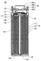
- FIG. 1 is a cross-sectional view of a cylindrical nonaqueous electrolyte secondary battery according to an embodiment.
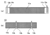
- FIG. 2A is a plan view of a negative electrode plate according to an embodiment.
- FIG. 2B is a plan view of the positive electrode plate according to the embodiment.
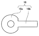
- FIG. 3 is a plan view of a current collecting plate used in the current collecting member according to the embodiment.
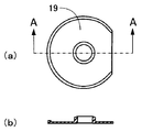
- FIG. 4A is a plan view of the first insulating plate according to the embodiment, and FIG. 4B is a cross-sectional view taken along line AA.
- FIG. 5 is a schematic cross-sectional view illustrating a state in which the first insulating plate according to the embodiment is attached to the current collector plate.
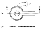
- 6A is a plan view of a current collecting member according to an embodiment
- FIG. 6B is a cross-sectional view taken along the line BB.
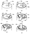
- 7A to 7F are perspective views showing a method of connecting a positive electrode lead led out from an electrode body according to an embodiment to
- the cylindrical nonaqueous electrolyte secondary battery 10 includes a bottomed cylindrical outer can 25, an electrode body 16 inserted into the outer can 25, and an opening of the outer can 25. It has the sealing body 24 which seals.
- the battery contains a non-aqueous electrolyte in which an electrolyte salt is dissolved in a non-aqueous solvent.
- the sealing body 24 includes an external terminal cap 24 a, an explosion-proof valve 24 b, and a terminal plate 24 d, and is caulked and fixed to the opening of the outer can 25 via a gasket 23.
- the external terminal cap 24a has a flange portion, and the flange portion is electrically connected to the explosion-proof valve 24b.
- the central part of the explosion-proof valve 24b and the terminal plate 24d are connected via an insulating plate 24c.
- the connecting portion breaks when the pressure inside the battery rises and reaches a predetermined value, and interrupts the current path inside the battery. When the pressure inside the battery further increases, the explosion-proof valve 24b breaks and the gas inside the battery is discharged.
- the electrode body 16 is composed of a negative electrode plate 11, a positive electrode plate 13 and a separator 15, and is produced by winding the negative electrode plate 11 and the positive electrode plate 13 with the separator 15 interposed therebetween.
- negative electrode leads 12a and 12b and positive electrode leads 14a and 14b are connected to the negative electrode plate 11 and the positive electrode plate 13, respectively.
- the negative electrode leads 12 a and 12 b are bent so as to be parallel to the bottom surface of the outer can 25.
- the negative electrode lead 12b on the outer peripheral side of the electrode body 16 is connected to the bottom of the outer can 25, and the negative electrode lead 12a on the inner peripheral side is connected to the connecting portion.
- the positive leads 14 a and 14 b are connected to the current collecting member 17.
- the current collecting member 17 is configured by attaching a first insulating plate 19 to a current collecting plate 18.
- the current collecting plate 18 has a flat plate portion 18a and a lead portion 18b.
- the positive leads 14 a and 14 b are connected to the flat plate portion 18 a, and the lead portion 18 b is connected to the terminal plate 24 d of the sealing body 24.
- the positive electrode plate is electrically connected to the external terminal cap 24a.
- a second insulating plate 20 is disposed between the electrode body 16 and the current collecting member 17.
- the second insulating plate 20 is not necessarily essential, but the second insulating plate 20 is used because the influence of the heat generated when the positive leads 14a and 14b are connected to the current collecting member 17 on the electrode body 16 can be reduced. It is preferable.
- An upper insulating plate 21 and a lower insulating plate 22 are disposed on the upper and lower portions of the electrode body 16 to which the current collecting member 17 is connected, respectively.
- the current collecting plate 18 can be produced by integrally molding from a single metal plate. It is preferable to provide an opening at the center of the flat plate portion 18a so that the electrolyte quickly penetrates into the electrode body during injection.
- the current collector plate does not necessarily have a lead portion, and the lead plate may be connected to a current collector plate composed of only a flat plate portion.
- a metal that can exist stably even when exposed to the potential of the positive electrode in the electrolytic solution can be used.
- a non-aqueous electrolyte aluminum and an aluminum alloy can be used.
- the first insulating plate 19 is manufactured by molding an insulating resin.
- a polypropylene resin can be used as the insulating resin.
- the first insulating plate 19 has an opening as shown in FIG.
- the electrolyte can quickly penetrate into the electrode body by providing the first insulating plate with the opening.
- Projections are provided on the outer peripheral portion and the inner peripheral portion of the first insulating plate 19.
- no protrusion is provided on a portion of the outer peripheral portion of the first insulating plate 19 where the lead portion 18b of the current collector plate 18 is disposed.
- the protrusions do not need to be provided on the entire outer peripheral portion of the first insulating plate, and the above-described effect is exhibited even if there is a region where there is no protrusion as long as the current collector plate does not pass.
- the protrusion on the inner periphery is molded so as to be inserted into the opening of the current collector plate 18.
- the protrusion of an inner peripheral part can be utilized.
- a method of attaching the first insulating plate 19 to the current collector plate 18 is as follows. First, as shown in FIG. 5, the protrusion on the inner peripheral portion of the first insulating plate is inserted into the opening of the current collecting plate 18, and the first insulating plate 19 is fitted to the current collecting plate 18. Then, the pin of the pressing jig 26 is inserted into the opening of the first insulating plate 19, and the protrusion on the inner peripheral portion is hot pressed.
- the surface temperature of the pressing jig at this time is preferably 120 to 180 ° C.
- the first insulating plate can be produced by injection molding an insulating resin into a shape shown in FIG. 6 in advance.
- a resin having elasticity such as polypropylene resin
- the first insulating plate has elasticity. Therefore, it is possible to press-fit a protrusion of the first insulating plate having an outer diameter larger than the inner diameter of the opening of the current collector plate into the opening of the current collector plate.
- the first insulating plate is attached to the current collector plate using the protrusion on the inner peripheral portion of the first insulating plate, but the protrusion provided on the outer peripheral portion of the first insulating plate can also be used.
- the first insulating plate can be attached to the current collector plate by bending the tip of the protrusion on the outer peripheral portion toward the inner peripheral portion so as to cover the current collector plate. It is also possible to produce the first insulating plate in advance by injecting an insulating resin into a shape in which the tip of the protrusion on the outer peripheral portion is bent toward the inner peripheral portion.
- An adhesive can also be used as means for attaching the first insulating plate to the current collector plate.
- coating an adhesive to the surface of either one of a current collecting plate and a 1st insulating board is mentioned.
- the pressure-sensitive adhesive it is possible to prevent displacement of the current collector plate on the first insulating plate during pressing.
- an adhesive it is preferably used in combination with a hot press, but it is also possible to use only an adhesive as means for attaching the first insulating plate to the current collector plate.
- thermoplastic resins such as a rubber-based pressure-sensitive adhesive, an acrylic resin, a vinyl resin, a fluororesin, and a polyamide resin can be used.
- thermosetting resins such as an amino resin, a phenol resin, a polyester resin, and an epoxy resin
- a double-sided tape in which the adhesive is applied to both surfaces of a substrate such as a nonwoven fabric can be used.
- FIG. 7A A method of connecting the positive electrode lead to the current collecting member will be described with reference to FIG.
- Two positive leads are led out from the wound electrode body 16 (FIG. 7A).
- the second insulating plate 20 is disposed on the electrode body 16 while the first positive electrode lead 14a on the inner peripheral side of the electrode body is inserted into the through hole 20a (FIG. 7B).
- the positive leads 14a and 14b are bent to the outside of the electrode body 16 (FIG. 7C), and the current collecting member 17 is disposed (FIG. 7D).
- the positive leads 14a and 14b are bent on the current collecting member 17 and connected to the current collecting member 17 (FIG. 7E). Laser welding can be used as a connection method. Finally, in order to insert the electrode body 16 into the outer can 25, the lead portion 18b is bent at an angle of 90 ° (FIG. 7F).
- the negative electrode plate 11 has a negative electrode current collector and a negative electrode mixture layer 11a formed on both surfaces of the negative electrode current collector.
- the negative electrode leads 12a and 12b are connected to the negative electrode current collector exposed portions 11b provided at both ends of the negative electrode plate 11, respectively, but the negative electrode lead may be connected to only one of them.
- the number of negative electrode leads is not particularly limited.
- a copper foil is preferably used as the negative electrode current collector.
- the negative electrode mixture layer 11a can be formed by applying and drying a negative electrode mixture slurry containing a negative electrode active material on a negative electrode current collector. In addition to the negative electrode active material, a binder or a conductive agent can be added to the negative electrode mixture slurry.
- the formed negative electrode mixture layer 11a is compressed with a roller, and the electrode plate after the compression is cut into a predetermined size, whereby the negative electrode plate 11 is obtained.
- a carbon material or a metal material capable of inserting and extracting lithium ions can be used as the negative electrode active material.
- the carbon material include graphite such as natural graphite and artificial graphite.
- the metal material include silicon and tin, and oxides thereof.
- the carbon material and the metal material can be used alone or in admixture of two or more. For example, graphite and silicon oxide can be mixed and used.
- the positive electrode plate 13 has a positive electrode current collector and a positive electrode mixture layer 13a formed on both surfaces of the positive electrode current collector.
- the first positive electrode lead and the second positive electrode lead 14b are connected to each of the two positive electrode current collector exposed portions 13b provided on the positive electrode plate 13, but the number of positive electrode leads is the same as that of the present embodiment. Without being limited, three or more positive electrode leads can be used.
- As the positive electrode current collector an aluminum foil is preferably used.
- the positive electrode mixture layer 13a can be formed by applying and drying a positive electrode mixture slurry containing a positive electrode active material on a positive electrode current collector. In addition to the positive electrode active material, a binder or a conductive agent can be added to the positive electrode mixture slurry. The formed positive electrode mixture layer 13a is compressed with a roller, and the electrode plate after the compression is cut into a predetermined dimension, whereby the positive electrode plate 13 is obtained.
- a lithium transition metal composite oxide capable of inserting and extracting lithium ions can be used.
- the lithium transition metal composite oxide include general formula LiMO 2 (M is at least one of Co, Ni, and Mn), LiMn 2 O 4, and LiFePO 4 . These can be used alone or in admixture of two or more, and at least one selected from the group consisting of Al, Ti, Mg, and Zr can be added or substituted with a transition metal element.
- a microporous film mainly composed of polyolefin such as polyethylene or polypropylene can be used as the separator.
- the microporous membrane can be used singly or as a laminate of two or more layers.
- a layer mainly composed of polyethylene having a low melting point is used as an intermediate layer and polypropylene having excellent oxidation resistance is used as a surface layer.
- inorganic particles such as aluminum oxide (Al 2 O 3 ), titanium oxide (TiO 2 ), and silicon oxide (SiO 2 ) can be added to the separator. Such inorganic particles can be carried in the separator and can be applied together with a binder on the separator surface.
- non-aqueous electrolyte a solution obtained by dissolving a lithium salt as an electrolyte salt in a non-aqueous solvent as a solvent can be used. Moreover, it can replace with a non-aqueous solvent and can also use the non-aqueous electrolyte using the gel-like polymer.
- a cyclic carbonate ester As the non-aqueous solvent, a cyclic carbonate ester, a chain carbonate ester, a cyclic carboxylic acid ester and a chain carboxylic acid ester can be used, and these are preferably used in combination of two or more.
- the cyclic carbonate include ethylene carbonate (EC), propylene carbonate (PC), and butylene carbonate (BC).
- a cyclic carbonate in which part of hydrogen is substituted with fluorine such as fluoroethylene carbonate (FEC)
- the chain carbonate include dimethyl carbonate (DMC), ethyl methyl carbonate (EMC), diethyl carbonate (DEC), and methyl propyl carbonate (MPC).
- Examples of cyclic carboxylic acid esters include ⁇ -butyrolactone ( ⁇ -BL) and ⁇ -valerolactone ( ⁇ -VL).
- Examples of chain carboxylic acid esters include methyl pivalate, ethyl pivalate, methyl isobutyrate and methyl Pionate is exemplified.
- lithium salts examples include LiPF 6 , LiBF 4 , LiCF 3 SO 3 , LiN (CF 3 SO 2 ) 2 , LiN (C 2 F 5 SO 2 ) 2 , LiN (CF 3 SO 2 ) (C 4 F 9 SO 2 ), LiC (CF 3 SO 2 ) 3 , LiC (C 2 F 5 SO 2 ) 3 , LiAsF 6 , LiClO 4 , Li 2 B 10 Cl 10 and Li 2 B 12 Cl 12 .
- LiPF 6 is particularly preferable, and the concentration in the nonaqueous electrolyte is preferably 0.5 to 2.0 mol / L.
- Other lithium salts such as LiBF 4 may be mixed with LiPF 6 .
- the present invention it is possible to provide a cylindrical battery excellent in productivity and quality while having a positive electrode plate to which a plurality of positive electrode leads are connected.
- INDUSTRIAL APPLICABILITY Since the present invention can provide a cylindrical battery suitable for applications requiring high output, such as electric tools, assist bicycles, and hybrid electric vehicles, the industrial applicability is great.
- Nonaqueous electrolyte secondary battery 11 Negative electrode plates 12a and 12b Negative electrode lead 13 Positive electrode plates 14a and 14b Positive electrode lead 15 Separator 16 Electrode body 17 Current collecting member 18 Current collecting plate 18a Flat plate portion 18b Lead portion 19 First insulating plate 20 Second Insulating plate 24 Sealing body 25 Exterior can
Landscapes
- Chemical & Material Sciences (AREA)
- Chemical Kinetics & Catalysis (AREA)
- Electrochemistry (AREA)
- General Chemical & Material Sciences (AREA)
- Engineering & Computer Science (AREA)
- Manufacturing & Machinery (AREA)
- Materials Engineering (AREA)
- Connection Of Batteries Or Terminals (AREA)
- Secondary Cells (AREA)
Abstract
Description
負極板と複数の正極リードが接続された正極板がセパレータを介して巻回された電極体と、電解液と、電極体と電解液を収容する有底筒状の外装缶と、外装缶の開口部を封止する封口体と、を備え、
正極リードが、電極体上に配置された集電部材の外周部を経由して集電部材の電池外方側の面に接続され、集電部材が前記正極リードに接続される集電板と前記集電板の電池内方側の面上に取り付けられている第1絶縁板を有することを特徴としている。
11 負極板
12a、12b 負極リード
13 正極板
14a、14b 正極リード
15 セパレータ
16 電極体
17 集電部材
18 集電板
18a 平板部
18b リード部
19 第1絶縁板
20 第2絶縁板
24 封口体
25 外装缶
Claims (10)
- 負極板と複数の正極リードが接続された正極板がセパレータを介して巻回された電極体と、
電解液と、
前記電極体と前記電解液を収容する有底筒状の外装缶と、
前記外装缶の開口部を封止する封口体と、を備え、
前記正極リードが、前記電極体上に配置された集電部材の外周部を経由して前記集電部材の電池外方側の面に接続され、
前記集電部材が前記正極リードに接続される集電板と前記集電板の電池内方側の面に取り付けられている第1絶縁板を有する、
円筒形電池。 - 前記集電板が、前記正極リードに接続される平板部と前記封口体に接続されるリード部を有し、前記平板部に開口が設けられている請求項1記載の円筒形電池。
- 前記第1絶縁板の外周部に電池外方に向けて突出する突起が設けられ、前記集電板の平板部が前記突起に囲まれる領域内に配置されている請求項1又は2に記載の円筒形電池。
- 前記第1絶縁板が前記集電板の開口に挿入される突起を有し、前記開口から突出する前記突起が前記集電板の平板部の少なくとも一部を覆っている請求項2又は3に記載の円筒形電池。
- 前記集電板の平板部と前記第1絶縁板の間に粘着剤が配置されている請求項1から4のいずれかに記載の円筒形電池。
- 前記正極リードのうち少なくとも1本を挿入する貫通孔を有している第2絶縁板が、前記第1絶縁板と前記電極体の間に配置されている請求項1から5のいずれかに記載の円筒形電池。
- 前記集電板がアルミニウム及びアルミニウム合金のいずれか一方からなる請求項1から6のいずれかに記載の円筒形電池。
- 開口を有する集電板に絶縁板が取り付けられた円筒形電池用集電部材であって、
前記絶縁板が前記集電板の開口に挿入される突起を有し、前記開口から突出する前記突起が前記集電板の少なくとも一部を覆う、
円筒形電池用集電部材。 - 前記集電板がアルミニウム及びアルミニウム合金のいずれか一方からなる請求項8に記載の円筒形電池用集電部材。
- 開口を有する集電板に絶縁板が取り付けられた円筒形電池用集電部材の製造方法であって、
前記集電板の開口に前記絶縁板の突起を挿入し、前記集電板に前記絶縁板を嵌め合わせるステップと、
前記開口から突出する前記突起が前記集電板の少なくとも一部を覆うように前記突起をホットプレスするステップと、
を備える円筒形電池用集電部材の製造方法。
Priority Applications (3)
| Application Number | Priority Date | Filing Date | Title |
|---|---|---|---|
| US15/564,238 US10263237B2 (en) | 2015-04-27 | 2016-03-18 | Cylindrical battery, and collector member used therefor, and manufacturing method thereof |
| CN201680021459.7A CN107534122B (zh) | 2015-04-27 | 2016-03-18 | 圆筒形电池、以及用于其的集电部件及其制造方法 |
| JP2017515367A JP6631626B2 (ja) | 2015-04-27 | 2016-03-18 | 円筒形電池、並びにそれに用いる集電部材及びその製造方法 |
Applications Claiming Priority (2)
| Application Number | Priority Date | Filing Date | Title |
|---|---|---|---|
| JP2015090136 | 2015-04-27 | ||
| JP2015-090136 | 2015-04-27 |
Publications (1)
| Publication Number | Publication Date |
|---|---|
| WO2016174811A1 true WO2016174811A1 (ja) | 2016-11-03 |
Family
ID=57199076
Family Applications (1)
| Application Number | Title | Priority Date | Filing Date |
|---|---|---|---|
| PCT/JP2016/001576 Ceased WO2016174811A1 (ja) | 2015-04-27 | 2016-03-18 | 円筒形電池、並びにそれに用いる集電部材及びその製造方法 |
Country Status (4)
| Country | Link |
|---|---|
| US (1) | US10263237B2 (ja) |
| JP (1) | JP6631626B2 (ja) |
| CN (1) | CN107534122B (ja) |
| WO (1) | WO2016174811A1 (ja) |
Cited By (10)
| Publication number | Priority date | Publication date | Assignee | Title |
|---|---|---|---|---|
| WO2018180828A1 (ja) * | 2017-03-29 | 2018-10-04 | 三洋電機株式会社 | 円筒形電池 |
| JPWO2018179968A1 (ja) * | 2017-03-30 | 2020-02-06 | パナソニックIpマネジメント株式会社 | 巻回型電池 |
| WO2021024734A1 (ja) * | 2019-08-08 | 2021-02-11 | 株式会社村田製作所 | 二次電池、電池パック、電子機器、電動工具及び電動車両 |
| US11127982B2 (en) * | 2018-04-12 | 2021-09-21 | Ningde Amperex Technology Limited | Electrode assembly and battery with sectioned active layers |
| JPWO2021192405A1 (ja) * | 2020-03-25 | 2021-09-30 | ||
| US11315743B2 (en) | 2018-09-28 | 2022-04-26 | Taiyo Yuden Co., Ltd. | Method of producing electrochemical device using two welding electrodes to weld lead plates |
| US11393643B2 (en) | 2018-09-28 | 2022-07-19 | Taiyo Yuden Co., Ltd. | Electrochemical device and method of producing the same |
| JP2022110189A (ja) * | 2021-01-18 | 2022-07-29 | 株式会社Gsユアサ | 蓄電素子 |
| WO2022270280A1 (ja) * | 2021-06-25 | 2022-12-29 | 三洋電機株式会社 | 円筒形電池 |
| EP4303974A4 (en) * | 2021-03-05 | 2025-04-30 | Panasonic Energy Co., Ltd. | CYLINDRICAL BATTERY |
Families Citing this family (8)
| Publication number | Priority date | Publication date | Assignee | Title |
|---|---|---|---|---|
| US11431046B2 (en) * | 2018-08-21 | 2022-08-30 | Nio Technology (Anhui) Co., Ltd. | Lithium-ion cell using aluminum can |
| KR102821609B1 (ko) * | 2019-01-30 | 2025-06-16 | 주식회사 엘지에너지솔루션 | 원통형 이차 전지 및 이의 제조 방법 |
| US12191511B2 (en) * | 2019-06-20 | 2025-01-07 | Apple Inc. | Battery cell with serpentine tab |
| JP7398719B2 (ja) * | 2020-05-15 | 2023-12-15 | パナソニックIpマネジメント株式会社 | 密閉型電池 |
| EP4095973A4 (en) * | 2021-03-12 | 2024-10-16 | Hengdian Group DMEGC Magnetics Co., Ltd. | CYLINDRICAL LITHIUM-ION BATTERY AND MANUFACTURING METHOD THEREOF |
| US12476334B2 (en) | 2021-10-27 | 2025-11-18 | Hithium Tech Hk Limited | Manufacturing method of core assembly for battery, core assembly for battery, and battery pack |
| CN113904037A (zh) * | 2021-10-27 | 2022-01-07 | 厦门海辰新能源科技有限公司 | 电池单体和电池包 |
| CN117878380A (zh) * | 2024-01-11 | 2024-04-12 | 合肥国轩高科动力能源有限公司 | 锂离子电池 |
Citations (4)
| Publication number | Priority date | Publication date | Assignee | Title |
|---|---|---|---|---|
| JPS5298937A (en) * | 1976-02-13 | 1977-08-19 | Yuasa Battery Co Ltd | Enclosed alkaline storage battery |
| JPS571402Y2 (ja) * | 1976-03-10 | 1982-01-09 | ||
| JPH11312509A (ja) * | 1998-04-28 | 1999-11-09 | Toyota Central Res & Dev Lab Inc | 電極巻回型電池 |
| JP2007335232A (ja) * | 2006-06-15 | 2007-12-27 | Matsushita Electric Ind Co Ltd | 二次電池およびその製造方法 |
Family Cites Families (16)
| Publication number | Priority date | Publication date | Assignee | Title |
|---|---|---|---|---|
| JPS5910537B2 (ja) * | 1978-05-16 | 1984-03-09 | 松下電器産業株式会社 | 円筒形蓄電池の製造法 |
| JP3692561B2 (ja) * | 1995-07-14 | 2005-09-07 | 株式会社デンソー | 電池 |
| JP3519953B2 (ja) * | 1998-08-27 | 2004-04-19 | 三洋電機株式会社 | 二次電池 |
| JP2000268803A (ja) * | 1999-03-19 | 2000-09-29 | Nec Corp | 非水電解液二次電池 |
| JP3351416B2 (ja) * | 2000-03-28 | 2002-11-25 | 松下電器産業株式会社 | 円筒形リチウムイオン二次電池 |
| JP2006147180A (ja) * | 2004-11-16 | 2006-06-08 | Toshiba Corp | 非水電解質二次電池 |
| US8236441B2 (en) * | 2007-07-24 | 2012-08-07 | A123 Systems, Inc. | Battery cell design and methods of its construction |
| JP2009129553A (ja) * | 2007-11-20 | 2009-06-11 | Sony Corp | 電池 |
| US20100233524A1 (en) * | 2008-05-28 | 2010-09-16 | Yasuhiko Hina | Cylindrical non-aqueous electrolyte secondary battery |
| JP5171401B2 (ja) * | 2008-06-04 | 2013-03-27 | 日立ビークルエナジー株式会社 | リチウム二次電池 |
| JP5420888B2 (ja) * | 2008-12-15 | 2014-02-19 | パナソニック株式会社 | 電池 |
| CN102160208A (zh) * | 2009-06-22 | 2011-08-17 | 松下电器产业株式会社 | 电池和电池组 |
| WO2011067931A1 (ja) * | 2009-12-04 | 2011-06-09 | パナソニック株式会社 | 密閉型二次電池 |
| JP5527176B2 (ja) * | 2010-11-25 | 2014-06-18 | ソニー株式会社 | 非水電解質電池 |
| WO2012105362A1 (ja) * | 2011-02-03 | 2012-08-09 | 三洋電機株式会社 | 非水電解液二次電池 |
| WO2016098291A1 (ja) * | 2014-12-16 | 2016-06-23 | 三洋電機株式会社 | 円筒形電池 |
-
2016
- 2016-03-18 US US15/564,238 patent/US10263237B2/en active Active
- 2016-03-18 WO PCT/JP2016/001576 patent/WO2016174811A1/ja not_active Ceased
- 2016-03-18 JP JP2017515367A patent/JP6631626B2/ja active Active
- 2016-03-18 CN CN201680021459.7A patent/CN107534122B/zh active Active
Patent Citations (4)
| Publication number | Priority date | Publication date | Assignee | Title |
|---|---|---|---|---|
| JPS5298937A (en) * | 1976-02-13 | 1977-08-19 | Yuasa Battery Co Ltd | Enclosed alkaline storage battery |
| JPS571402Y2 (ja) * | 1976-03-10 | 1982-01-09 | ||
| JPH11312509A (ja) * | 1998-04-28 | 1999-11-09 | Toyota Central Res & Dev Lab Inc | 電極巻回型電池 |
| JP2007335232A (ja) * | 2006-06-15 | 2007-12-27 | Matsushita Electric Ind Co Ltd | 二次電池およびその製造方法 |
Cited By (19)
| Publication number | Priority date | Publication date | Assignee | Title |
|---|---|---|---|---|
| JPWO2018180828A1 (ja) * | 2017-03-29 | 2020-05-14 | 三洋電機株式会社 | 円筒形電池 |
| WO2018180828A1 (ja) * | 2017-03-29 | 2018-10-04 | 三洋電機株式会社 | 円筒形電池 |
| US11011806B2 (en) | 2017-03-29 | 2021-05-18 | Sanyo Electric Co., Ltd. | Cylindrical battery |
| JP7006683B2 (ja) | 2017-03-29 | 2022-01-24 | 三洋電機株式会社 | 円筒形電池 |
| JPWO2018179968A1 (ja) * | 2017-03-30 | 2020-02-06 | パナソニックIpマネジメント株式会社 | 巻回型電池 |
| US11817547B2 (en) | 2017-03-30 | 2023-11-14 | Panasonic Intellectual Property Management Co., Ltd. | Wound-type battery |
| JP7122660B2 (ja) | 2017-03-30 | 2022-08-22 | パナソニックIpマネジメント株式会社 | 巻回型電池 |
| US11127982B2 (en) * | 2018-04-12 | 2021-09-21 | Ningde Amperex Technology Limited | Electrode assembly and battery with sectioned active layers |
| US11315743B2 (en) | 2018-09-28 | 2022-04-26 | Taiyo Yuden Co., Ltd. | Method of producing electrochemical device using two welding electrodes to weld lead plates |
| US11393643B2 (en) | 2018-09-28 | 2022-07-19 | Taiyo Yuden Co., Ltd. | Electrochemical device and method of producing the same |
| JPWO2021024734A1 (ja) * | 2019-08-08 | 2021-02-11 | ||
| JP7047978B2 (ja) | 2019-08-08 | 2022-04-05 | 株式会社村田製作所 | 二次電池、電池パック、電子機器、電動工具及び電動車両 |
| WO2021024734A1 (ja) * | 2019-08-08 | 2021-02-11 | 株式会社村田製作所 | 二次電池、電池パック、電子機器、電動工具及び電動車両 |
| US12046777B2 (en) | 2019-08-08 | 2024-07-23 | Murata Manufacturing Co., Ltd. | Secondary battery, battery pack, electronic device, electric tool, and electric vehicle |
| JPWO2021192405A1 (ja) * | 2020-03-25 | 2021-09-30 | ||
| JP2022110189A (ja) * | 2021-01-18 | 2022-07-29 | 株式会社Gsユアサ | 蓄電素子 |
| JP7749920B2 (ja) | 2021-01-18 | 2025-10-07 | 株式会社Gsユアサ | 蓄電素子 |
| EP4303974A4 (en) * | 2021-03-05 | 2025-04-30 | Panasonic Energy Co., Ltd. | CYLINDRICAL BATTERY |
| WO2022270280A1 (ja) * | 2021-06-25 | 2022-12-29 | 三洋電機株式会社 | 円筒形電池 |
Also Published As
| Publication number | Publication date |
|---|---|
| CN107534122A (zh) | 2018-01-02 |
| CN107534122B (zh) | 2020-09-29 |
| JP6631626B2 (ja) | 2020-01-15 |
| US20180130994A1 (en) | 2018-05-10 |
| US10263237B2 (en) | 2019-04-16 |
| JPWO2016174811A1 (ja) | 2018-02-15 |
Similar Documents
| Publication | Publication Date | Title |
|---|---|---|
| JP6631626B2 (ja) | 円筒形電池、並びにそれに用いる集電部材及びその製造方法 | |
| JP6593344B2 (ja) | 円筒形電池 | |
| JP7006683B2 (ja) | 円筒形電池 | |
| CN107431178B (zh) | 圆筒形电池 | |
| JP5505218B2 (ja) | 密閉型蓄電池 | |
| JP6250921B2 (ja) | 電池 | |
| KR101224528B1 (ko) | 리튬 이온 2차 전지 | |
| US20180047949A1 (en) | Cylindrical battery and method for producing the same | |
| JP2012124146A (ja) | 二次電池、バッテリユニットおよびバッテリモジュール | |
| CN107710459A (zh) | 电池及电池包 | |
| WO2012147782A1 (ja) | 密閉型電池及びその製造方法 | |
| CN113517501A (zh) | 一种电池及含该电池的用电装置 | |
| JP4720384B2 (ja) | バイポーラ電池 | |
| JP4670275B2 (ja) | バイポーラ電池および組電池 | |
| JP5334109B2 (ja) | ラミネート形電池 | |
| JP2004171954A (ja) | ラミネート二次電池、複数のラミネート二次電池からなる組電池モジュール、複数の組電池モジュールからなる組電池ならびにこれらいずれかの電池を搭載した電気自動車 | |
| KR101722662B1 (ko) | 파우치형 이차 전지 | |
| JP2000357493A (ja) | 枠付き電池 | |
| JP4135353B2 (ja) | ラミネートシートを外装ケースに用いた非水電解液二次電池及びこれを内蔵した機器 | |
| JP4710276B2 (ja) | 二次電池用外装部材及び二次電池 | |
| KR101458259B1 (ko) | 파우치형 이차전지 및 그 제조방법 | |
| KR100608103B1 (ko) | 구리전극단자를 이용한 리튬이온폴리머2차전지의 결합 구조 | |
| WO2022168622A1 (ja) | 二次電池、電子機器及び電動工具 | |
| KR20250088155A (ko) | 양극, 이를 포함하는 전극 조립체, 및 이를 포함하는 리튬 이차전지 | |
| JP2004087431A (ja) | 薄型電池 |
Legal Events
| Date | Code | Title | Description |
|---|---|---|---|
| 121 | Ep: the epo has been informed by wipo that ep was designated in this application |
Ref document number: 16786093 Country of ref document: EP Kind code of ref document: A1 |
|
| WWE | Wipo information: entry into national phase |
Ref document number: 15564238 Country of ref document: US |
|
| ENP | Entry into the national phase |
Ref document number: 2017515367 Country of ref document: JP Kind code of ref document: A |
|
| NENP | Non-entry into the national phase |
Ref country code: DE |
|
| 122 | Ep: pct application non-entry in european phase |
Ref document number: 16786093 Country of ref document: EP Kind code of ref document: A1 |