WO2022168622A1 - 二次電池、電子機器及び電動工具 - Google Patents
二次電池、電子機器及び電動工具 Download PDFInfo
- Publication number
- WO2022168622A1 WO2022168622A1 PCT/JP2022/002023 JP2022002023W WO2022168622A1 WO 2022168622 A1 WO2022168622 A1 WO 2022168622A1 JP 2022002023 W JP2022002023 W JP 2022002023W WO 2022168622 A1 WO2022168622 A1 WO 2022168622A1
- Authority
- WO
- WIPO (PCT)
- Prior art keywords
- negative electrode
- positive electrode
- active material
- electrode active
- welded
- Prior art date
Links
- 238000004804 winding Methods 0.000 claims abstract description 90
- 239000007773 negative electrode material Substances 0.000 claims abstract description 85
- 239000007774 positive electrode material Substances 0.000 claims abstract description 68
- 239000011888 foil Substances 0.000 claims abstract description 37
- 238000005452 bending Methods 0.000 claims description 6
- HBBGRARXTFLTSG-UHFFFAOYSA-N Lithium ion Chemical compound [Li+] HBBGRARXTFLTSG-UHFFFAOYSA-N 0.000 description 56
- 229910001416 lithium ion Inorganic materials 0.000 description 56
- 239000010410 layer Substances 0.000 description 31
- 238000010586 diagram Methods 0.000 description 21
- 238000003466 welding Methods 0.000 description 19
- 230000000052 comparative effect Effects 0.000 description 16
- 238000000034 method Methods 0.000 description 11
- -1 polybutylene terephthalate Polymers 0.000 description 11
- WHXSMMKQMYFTQS-UHFFFAOYSA-N Lithium Chemical compound [Li] WHXSMMKQMYFTQS-UHFFFAOYSA-N 0.000 description 9
- 238000001514 detection method Methods 0.000 description 9
- 229910052744 lithium Inorganic materials 0.000 description 9
- 239000000463 material Substances 0.000 description 9
- 229920005989 resin Polymers 0.000 description 9
- 239000011347 resin Substances 0.000 description 9
- 239000008151 electrolyte solution Substances 0.000 description 8
- 238000004519 manufacturing process Methods 0.000 description 8
- 238000003860 storage Methods 0.000 description 8
- PXHVJJICTQNCMI-UHFFFAOYSA-N Nickel Chemical compound [Ni] PXHVJJICTQNCMI-UHFFFAOYSA-N 0.000 description 6
- 239000011248 coating agent Substances 0.000 description 6
- 238000000576 coating method Methods 0.000 description 6
- 238000007599 discharging Methods 0.000 description 6
- 229910052751 metal Inorganic materials 0.000 description 6
- 235000002639 sodium chloride Nutrition 0.000 description 6
- 229910052782 aluminium Inorganic materials 0.000 description 5
- XAGFODPZIPBFFR-UHFFFAOYSA-N aluminium Chemical compound [Al] XAGFODPZIPBFFR-UHFFFAOYSA-N 0.000 description 5
- 230000000694 effects Effects 0.000 description 5
- 239000007769 metal material Substances 0.000 description 5
- 238000012986 modification Methods 0.000 description 5
- 230000004048 modification Effects 0.000 description 5
- 150000003839 salts Chemical class 0.000 description 5
- OKTJSMMVPCPJKN-UHFFFAOYSA-N Carbon Chemical compound [C] OKTJSMMVPCPJKN-UHFFFAOYSA-N 0.000 description 4
- 239000003575 carbonaceous material Substances 0.000 description 4
- 239000002131 composite material Substances 0.000 description 4
- 239000004020 conductor Substances 0.000 description 4
- 239000003792 electrolyte Substances 0.000 description 4
- 239000011810 insulating material Substances 0.000 description 4
- 239000002184 metal Substances 0.000 description 4
- 229910000838 Al alloy Inorganic materials 0.000 description 3
- RYGMFSIKBFXOCR-UHFFFAOYSA-N Copper Chemical compound [Cu] RYGMFSIKBFXOCR-UHFFFAOYSA-N 0.000 description 3
- 229910000881 Cu alloy Inorganic materials 0.000 description 3
- 239000002033 PVDF binder Substances 0.000 description 3
- 239000004743 Polypropylene Substances 0.000 description 3
- VYPSYNLAJGMNEJ-UHFFFAOYSA-N Silicium dioxide Chemical compound O=[Si]=O VYPSYNLAJGMNEJ-UHFFFAOYSA-N 0.000 description 3
- 239000003125 aqueous solvent Substances 0.000 description 3
- 238000006243 chemical reaction Methods 0.000 description 3
- 150000001875 compounds Chemical class 0.000 description 3
- 239000010949 copper Substances 0.000 description 3
- 229910052802 copper Inorganic materials 0.000 description 3
- 239000011883 electrode binding agent Substances 0.000 description 3
- 239000010954 inorganic particle Substances 0.000 description 3
- 229910003002 lithium salt Inorganic materials 0.000 description 3
- 159000000002 lithium salts Chemical group 0.000 description 3
- 238000005259 measurement Methods 0.000 description 3
- 239000000203 mixture Substances 0.000 description 3
- 229910052759 nickel Inorganic materials 0.000 description 3
- 229920001707 polybutylene terephthalate Polymers 0.000 description 3
- 229920001155 polypropylene Polymers 0.000 description 3
- 229920002981 polyvinylidene fluoride Polymers 0.000 description 3
- 238000003825 pressing Methods 0.000 description 3
- 239000002904 solvent Substances 0.000 description 3
- 230000037303 wrinkles Effects 0.000 description 3
- XEEYBQQBJWHFJM-UHFFFAOYSA-N Iron Chemical compound [Fe] XEEYBQQBJWHFJM-UHFFFAOYSA-N 0.000 description 2
- 229910000990 Ni alloy Inorganic materials 0.000 description 2
- 229910019142 PO4 Inorganic materials 0.000 description 2
- RTAQQCXQSZGOHL-UHFFFAOYSA-N Titanium Chemical compound [Ti] RTAQQCXQSZGOHL-UHFFFAOYSA-N 0.000 description 2
- 229910045601 alloy Inorganic materials 0.000 description 2
- 239000000956 alloy Substances 0.000 description 2
- 238000000231 atomic layer deposition Methods 0.000 description 2
- 239000013078 crystal Substances 0.000 description 2
- 230000007423 decrease Effects 0.000 description 2
- 238000009831 deintercalation Methods 0.000 description 2
- 229920001971 elastomer Polymers 0.000 description 2
- 229910002804 graphite Inorganic materials 0.000 description 2
- 239000010439 graphite Substances 0.000 description 2
- 238000009830 intercalation Methods 0.000 description 2
- 229910001496 lithium tetrafluoroborate Inorganic materials 0.000 description 2
- 239000003960 organic solvent Substances 0.000 description 2
- 239000010452 phosphate Substances 0.000 description 2
- 229920000642 polymer Polymers 0.000 description 2
- 239000005060 rubber Substances 0.000 description 2
- 239000010703 silicon Substances 0.000 description 2
- 239000000243 solution Substances 0.000 description 2
- 239000000758 substrate Substances 0.000 description 2
- 229920003051 synthetic elastomer Polymers 0.000 description 2
- 239000005061 synthetic rubber Substances 0.000 description 2
- 239000010936 titanium Substances 0.000 description 2
- 229910001339 C alloy Inorganic materials 0.000 description 1
- YCKRFDGAMUMZLT-UHFFFAOYSA-N Fluorine atom Chemical compound [F] YCKRFDGAMUMZLT-UHFFFAOYSA-N 0.000 description 1
- 229910013063 LiBF 4 Inorganic materials 0.000 description 1
- 229910013870 LiPF 6 Inorganic materials 0.000 description 1
- 229910001290 LiPF6 Inorganic materials 0.000 description 1
- 240000007594 Oryza sativa Species 0.000 description 1
- 235000007164 Oryza sativa Nutrition 0.000 description 1
- 239000004698 Polyethylene Substances 0.000 description 1
- 239000004642 Polyimide Substances 0.000 description 1
- 241000156302 Porcine hemagglutinating encephalomyelitis virus Species 0.000 description 1
- 229910000676 Si alloy Inorganic materials 0.000 description 1
- XUIMIQQOPSSXEZ-UHFFFAOYSA-N Silicon Chemical compound [Si] XUIMIQQOPSSXEZ-UHFFFAOYSA-N 0.000 description 1
- FAPWRFPIFSIZLT-UHFFFAOYSA-M Sodium chloride Chemical compound [Na+].[Cl-] FAPWRFPIFSIZLT-UHFFFAOYSA-M 0.000 description 1
- 239000002174 Styrene-butadiene Substances 0.000 description 1
- ATJFFYVFTNAWJD-UHFFFAOYSA-N Tin Chemical compound [Sn] ATJFFYVFTNAWJD-UHFFFAOYSA-N 0.000 description 1
- HCHKCACWOHOZIP-UHFFFAOYSA-N Zinc Chemical compound [Zn] HCHKCACWOHOZIP-UHFFFAOYSA-N 0.000 description 1
- 230000002159 abnormal effect Effects 0.000 description 1
- 230000005856 abnormality Effects 0.000 description 1
- 239000006230 acetylene black Substances 0.000 description 1
- 239000011149 active material Substances 0.000 description 1
- 239000000654 additive Substances 0.000 description 1
- WNROFYMDJYEPJX-UHFFFAOYSA-K aluminium hydroxide Chemical compound [OH-].[OH-].[OH-].[Al+3] WNROFYMDJYEPJX-UHFFFAOYSA-K 0.000 description 1
- 229910003481 amorphous carbon Inorganic materials 0.000 description 1
- 239000010426 asphalt Substances 0.000 description 1
- 229910001593 boehmite Inorganic materials 0.000 description 1
- MTAZNLWOLGHBHU-UHFFFAOYSA-N butadiene-styrene rubber Chemical compound C=CC=C.C=CC1=CC=CC=C1 MTAZNLWOLGHBHU-UHFFFAOYSA-N 0.000 description 1
- 229910052799 carbon Inorganic materials 0.000 description 1
- 150000007942 carboxylates Chemical class 0.000 description 1
- 150000005678 chain carbonates Chemical class 0.000 description 1
- 239000012141 concentrate Substances 0.000 description 1
- 229920001940 conductive polymer Polymers 0.000 description 1
- PMHQVHHXPFUNSP-UHFFFAOYSA-M copper(1+);methylsulfanylmethane;bromide Chemical compound Br[Cu].CSC PMHQVHHXPFUNSP-UHFFFAOYSA-M 0.000 description 1
- 150000005676 cyclic carbonates Chemical class 0.000 description 1
- 238000000354 decomposition reaction Methods 0.000 description 1
- 230000006866 deterioration Effects 0.000 description 1
- 238000001035 drying Methods 0.000 description 1
- 238000005516 engineering process Methods 0.000 description 1
- 238000011156 evaluation Methods 0.000 description 1
- 238000000605 extraction Methods 0.000 description 1
- 239000011737 fluorine Substances 0.000 description 1
- 229910052731 fluorine Inorganic materials 0.000 description 1
- 239000000446 fuel Substances 0.000 description 1
- 229910021469 graphitizable carbon Inorganic materials 0.000 description 1
- FAHBNUUHRFUEAI-UHFFFAOYSA-M hydroxidooxidoaluminium Chemical compound O[Al]=O FAHBNUUHRFUEAI-UHFFFAOYSA-M 0.000 description 1
- 150000002500 ions Chemical class 0.000 description 1
- 229910052742 iron Inorganic materials 0.000 description 1
- 230000001678 irradiating effect Effects 0.000 description 1
- 238000005304 joining Methods 0.000 description 1
- 239000003273 ketjen black Substances 0.000 description 1
- 150000002596 lactones Chemical class 0.000 description 1
- MHCFAGZWMAWTNR-UHFFFAOYSA-M lithium perchlorate Chemical compound [Li+].[O-]Cl(=O)(=O)=O MHCFAGZWMAWTNR-UHFFFAOYSA-M 0.000 description 1
- OWNSEPXOQWKTKG-UHFFFAOYSA-M lithium;methanesulfonate Chemical compound [Li+].CS([O-])(=O)=O OWNSEPXOQWKTKG-UHFFFAOYSA-M 0.000 description 1
- VTHJTEIRLNZDEV-UHFFFAOYSA-L magnesium dihydroxide Chemical compound [OH-].[OH-].[Mg+2] VTHJTEIRLNZDEV-UHFFFAOYSA-L 0.000 description 1
- 239000000347 magnesium hydroxide Substances 0.000 description 1
- 229910001862 magnesium hydroxide Inorganic materials 0.000 description 1
- 238000002844 melting Methods 0.000 description 1
- 230000008018 melting Effects 0.000 description 1
- 239000012528 membrane Substances 0.000 description 1
- 239000010445 mica Substances 0.000 description 1
- 229910052618 mica group Inorganic materials 0.000 description 1
- 238000012544 monitoring process Methods 0.000 description 1
- 150000002825 nitriles Chemical class 0.000 description 1
- 229910021470 non-graphitizable carbon Inorganic materials 0.000 description 1
- 239000011146 organic particle Substances 0.000 description 1
- TWNQGVIAIRXVLR-UHFFFAOYSA-N oxo(oxoalumanyloxy)alumane Chemical compound O=[Al]O[Al]=O TWNQGVIAIRXVLR-UHFFFAOYSA-N 0.000 description 1
- 230000002093 peripheral effect Effects 0.000 description 1
- 229920000573 polyethylene Polymers 0.000 description 1
- 229920001721 polyimide Polymers 0.000 description 1
- 239000002861 polymer material Substances 0.000 description 1
- 238000010248 power generation Methods 0.000 description 1
- 238000012545 processing Methods 0.000 description 1
- 230000008929 regeneration Effects 0.000 description 1
- 238000011069 regeneration method Methods 0.000 description 1
- 230000003014 reinforcing effect Effects 0.000 description 1
- 235000009566 rice Nutrition 0.000 description 1
- 238000007789 sealing Methods 0.000 description 1
- 239000004065 semiconductor Substances 0.000 description 1
- 229910052710 silicon Inorganic materials 0.000 description 1
- HBMJWWWQQXIZIP-UHFFFAOYSA-N silicon carbide Chemical compound [Si+]#[C-] HBMJWWWQQXIZIP-UHFFFAOYSA-N 0.000 description 1
- 239000000377 silicon dioxide Substances 0.000 description 1
- LIVNPJMFVYWSIS-UHFFFAOYSA-N silicon monoxide Chemical compound [Si-]#[O+] LIVNPJMFVYWSIS-UHFFFAOYSA-N 0.000 description 1
- 229910052814 silicon oxide Inorganic materials 0.000 description 1
- 239000011780 sodium chloride Substances 0.000 description 1
- 229910052596 spinel Inorganic materials 0.000 description 1
- 239000011029 spinel Substances 0.000 description 1
- 238000004544 sputter deposition Methods 0.000 description 1
- 239000011115 styrene butadiene Substances 0.000 description 1
- 229920003048 styrene butadiene rubber Polymers 0.000 description 1
- 239000000126 substance Substances 0.000 description 1
- 239000002344 surface layer Substances 0.000 description 1
- 230000003746 surface roughness Effects 0.000 description 1
- 239000000454 talc Substances 0.000 description 1
- 229910052623 talc Inorganic materials 0.000 description 1
- 229910052719 titanium Inorganic materials 0.000 description 1
- ITMCEJHCFYSIIV-UHFFFAOYSA-N triflic acid Chemical compound OS(=O)(=O)C(F)(F)F ITMCEJHCFYSIIV-UHFFFAOYSA-N 0.000 description 1
- XLYOFNOQVPJJNP-UHFFFAOYSA-N water Substances O XLYOFNOQVPJJNP-UHFFFAOYSA-N 0.000 description 1
- 229910052725 zinc Inorganic materials 0.000 description 1
- 239000011701 zinc Substances 0.000 description 1
Images


Classifications
-
- H—ELECTRICITY
- H01—ELECTRIC ELEMENTS
- H01M—PROCESSES OR MEANS, e.g. BATTERIES, FOR THE DIRECT CONVERSION OF CHEMICAL ENERGY INTO ELECTRICAL ENERGY
- H01M10/00—Secondary cells; Manufacture thereof
- H01M10/05—Accumulators with non-aqueous electrolyte
- H01M10/052—Li-accumulators
- H01M10/0525—Rocking-chair batteries, i.e. batteries with lithium insertion or intercalation in both electrodes; Lithium-ion batteries
-
- H—ELECTRICITY
- H01—ELECTRIC ELEMENTS
- H01M—PROCESSES OR MEANS, e.g. BATTERIES, FOR THE DIRECT CONVERSION OF CHEMICAL ENERGY INTO ELECTRICAL ENERGY
- H01M50/00—Constructional details or processes of manufacture of the non-active parts of electrochemical cells other than fuel cells, e.g. hybrid cells
- H01M50/50—Current conducting connections for cells or batteries
- H01M50/531—Electrode connections inside a battery casing
- H01M50/536—Electrode connections inside a battery casing characterised by the method of fixing the leads to the electrodes, e.g. by welding
-
- H—ELECTRICITY
- H01—ELECTRIC ELEMENTS
- H01M—PROCESSES OR MEANS, e.g. BATTERIES, FOR THE DIRECT CONVERSION OF CHEMICAL ENERGY INTO ELECTRICAL ENERGY
- H01M10/00—Secondary cells; Manufacture thereof
- H01M10/04—Construction or manufacture in general
- H01M10/0431—Cells with wound or folded electrodes
-
- H—ELECTRICITY
- H01—ELECTRIC ELEMENTS
- H01M—PROCESSES OR MEANS, e.g. BATTERIES, FOR THE DIRECT CONVERSION OF CHEMICAL ENERGY INTO ELECTRICAL ENERGY
- H01M10/00—Secondary cells; Manufacture thereof
- H01M10/05—Accumulators with non-aqueous electrolyte
- H01M10/058—Construction or manufacture
- H01M10/0587—Construction or manufacture of accumulators having only wound construction elements, i.e. wound positive electrodes, wound negative electrodes and wound separators
-
- H—ELECTRICITY
- H01—ELECTRIC ELEMENTS
- H01M—PROCESSES OR MEANS, e.g. BATTERIES, FOR THE DIRECT CONVERSION OF CHEMICAL ENERGY INTO ELECTRICAL ENERGY
- H01M50/00—Constructional details or processes of manufacture of the non-active parts of electrochemical cells other than fuel cells, e.g. hybrid cells
- H01M50/50—Current conducting connections for cells or batteries
- H01M50/531—Electrode connections inside a battery casing
- H01M50/538—Connection of several leads or tabs of wound or folded electrode stacks
-
- H—ELECTRICITY
- H01—ELECTRIC ELEMENTS
- H01M—PROCESSES OR MEANS, e.g. BATTERIES, FOR THE DIRECT CONVERSION OF CHEMICAL ENERGY INTO ELECTRICAL ENERGY
- H01M2220/00—Batteries for particular applications
- H01M2220/30—Batteries in portable systems, e.g. mobile phone, laptop
-
- Y—GENERAL TAGGING OF NEW TECHNOLOGICAL DEVELOPMENTS; GENERAL TAGGING OF CROSS-SECTIONAL TECHNOLOGIES SPANNING OVER SEVERAL SECTIONS OF THE IPC; TECHNICAL SUBJECTS COVERED BY FORMER USPC CROSS-REFERENCE ART COLLECTIONS [XRACs] AND DIGESTS
- Y02—TECHNOLOGIES OR APPLICATIONS FOR MITIGATION OR ADAPTATION AGAINST CLIMATE CHANGE
- Y02E—REDUCTION OF GREENHOUSE GAS [GHG] EMISSIONS, RELATED TO ENERGY GENERATION, TRANSMISSION OR DISTRIBUTION
- Y02E60/00—Enabling technologies; Technologies with a potential or indirect contribution to GHG emissions mitigation
- Y02E60/10—Energy storage using batteries
-
- Y—GENERAL TAGGING OF NEW TECHNOLOGICAL DEVELOPMENTS; GENERAL TAGGING OF CROSS-SECTIONAL TECHNOLOGIES SPANNING OVER SEVERAL SECTIONS OF THE IPC; TECHNICAL SUBJECTS COVERED BY FORMER USPC CROSS-REFERENCE ART COLLECTIONS [XRACs] AND DIGESTS
- Y02—TECHNOLOGIES OR APPLICATIONS FOR MITIGATION OR ADAPTATION AGAINST CLIMATE CHANGE
- Y02P—CLIMATE CHANGE MITIGATION TECHNOLOGIES IN THE PRODUCTION OR PROCESSING OF GOODS
- Y02P70/00—Climate change mitigation technologies in the production process for final industrial or consumer products
- Y02P70/50—Manufacturing or production processes characterised by the final manufactured product
Definitions
- the present invention relates to secondary batteries, electronic devices, and power tools.
- Lithium-ion batteries which are one type of secondary battery, are being developed for applications that require high output, such as power tools and automobiles.
- One method of achieving high power is high rate discharge, in which a relatively large current is drawn from the battery. Since high-rate discharge requires a large current, it is desirable to reduce the internal resistance of the battery.
- Patent Document 1 below describes a secondary battery having a structure in which a notch is provided on the outer periphery of a negative electrode current collector, and the winding end of the negative electrode current collector is aligned with the notch. Have been described.
- Patent Document 1 If the technology described in Patent Document 1 is applied to a lithium-ion battery with a tabless structure (a structure in which no tabs are provided to lead the output of the battery to the outside), the reaction area of the electrode is reduced, resulting in a decrease in battery performance. There is a risk that In addition, the secondary battery of Patent Document 1 lacks the viewpoint of improving the current collection efficiency based on the relationship between the winding end portion of the current collector and the joint (specifically, the welded portion). rice field.
- one of the objects of the present invention is to provide a secondary battery with improved current collection efficiency, an electronic device using the secondary battery, and an electric tool.
- the present invention A secondary battery in which an electrode winding body having a structure in which a strip-shaped positive electrode and a strip-shaped negative electrode are laminated with a separator interposed therebetween, and a positive electrode current collector plate and a negative electrode current collector plate are housed in a battery can,
- the positive electrode has a positive electrode active material coated portion coated with a positive electrode active material layer and a positive electrode active material uncoated portion on a strip-shaped positive electrode foil
- the negative electrode has a negative electrode active material coated portion coated with a negative electrode active material layer on a strip-shaped negative electrode foil, and a negative electrode active material uncoated portion extending in the longitudinal direction of the negative electrode foil,
- the positive electrode active material non-coated portion is welded to the positive electrode current collector plate on one end surface of the electrode winding body,
- the negative electrode active material non-coated portion is welded to the negative electrode current collector plate at the other end of the electrode winding body,
- Each of the positive electrode current collector plate and the negative electrode current collector plate
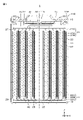
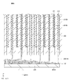
- FIG. 1 is a cross-sectional view of a lithium ion battery according to one embodiment.
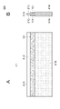
- 2A and 2B are diagrams for explaining a positive electrode according to one embodiment.
- 3A and 3B are diagrams for explaining a negative electrode according to one embodiment.
- FIG. 4 is a diagram showing a positive electrode, a negative electrode, and a separator before winding.
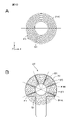
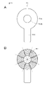
- FIG. 5A is a plan view of a positive current collector according to one embodiment
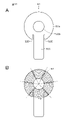
- FIG. 5B is a plan view of a negative current collector according to one embodiment.
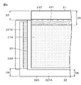
- FIG. 6 is a partially enlarged cross-sectional view for explaining the configuration of the electrode winding body according to one embodiment.
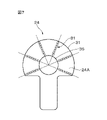
- FIG. 7 is a diagram for explaining an example of a group of welded portions that a positive current collector plate has.
- FIG. 1 is a cross-sectional view of a lithium ion battery according to one embodiment.
- 2A and 2B are diagrams for explaining a positive electrode according to one embodiment.
- 3A and 3B are
- FIG. 8 is a partially enlarged cross-sectional view for explaining the configuration of the electrode winding body according to one embodiment.
- FIG. 9 is a diagram for explaining an example of a welded portion group of a negative electrode current collector plate.
- FIG. 10A is a diagram for explaining an example of a winding start end portion and a winding end portion
- FIG. 10B is a diagram for explaining an example of the positional relationship between the winding end portion and the first welded portion and the second welded portion.
- FIG. 11A is a diagram for explaining another example of the winding start end portion and the winding end portion
- FIG. 11B is another example of the positional relationship between the winding end portion and the first and second welded portions. It is a figure for demonstrating an example.
- FIG. 10A is a diagram for explaining an example of a winding start end portion and a winding end portion
- FIG. 10B is a diagram for explaining an example of the positional relationship between the winding end portion and the first and second welded portions
- FIG. 12 is a diagram for explaining the reason why current collection efficiency deteriorates.
- FIG. 13 is a diagram for explaining the reason why the current collection efficiency is improved.
- FIG. 14 is a diagram for explaining the reason why the current collection efficiency is improved.
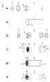
- 15A to 15F are diagrams explaining the assembly process of a lithium ion battery according to one embodiment.
- 16A and 16B are diagrams for explaining a modification.
- 17A and 17B are diagrams for explaining a modification.
- FIG. 18 is a connection diagram used for explaining a battery pack as an application example of the present invention.
- FIG. 19 is a connection diagram used for explaining a power tool as an application example of the present invention.
- FIG. 20 is a connection diagram used for explaining an electric vehicle as an application example of the present invention.
- FIG. 1 is a schematic cross-sectional view of a lithium ion battery 1.
- the lithium ion battery 1 is, for example, a cylindrical lithium ion battery 1 in which an electrode winding body 20 is housed inside a battery can 11 as shown in FIG. In the following description, unless otherwise specified, the horizontal direction toward the paper surface of FIG.
- the Z-axis direction is the X-axis direction
- the depth direction is the Y-axis direction
- the vertical direction 1, and the extending direction of the axis )) indicated by the dashed line in FIG. 1 is appropriately referred to as the Z-axis direction.
- the lithium ion battery 1 has a roughly cylindrical battery can 11 , and inside the battery can 11 , a pair of insulating plates 12 and 13 and an electrode winding 20 are provided.
- the lithium ion battery 1 may further include, for example, one or more of a thermal resistance (PTC) element and a reinforcing member inside the battery can 11 .
- PTC thermal resistance
- the battery can 11 is mainly a member that houses the electrode winding body 20 .
- the battery can 11 is, for example, a cylindrical container that is open at one end and closed at the other end. That is, the battery can 11 has one open end surface (open end surface 11N).
- the battery can 11 contains, for example, one or more of metal materials such as iron, aluminum, and alloys thereof.
- the surface of the battery can 11 may be plated with, for example, one or more of metal materials such as nickel.
- the insulating plates 12 and 13 are disk-shaped having surfaces substantially perpendicular to the central axis of the electrode winding body 20 (a direction passing through substantially the center of the end face of the electrode winding body 20 and parallel to the Z axis in FIG. 1). It is a board of Also, the insulating plates 12 and 13 are arranged, for example, so as to sandwich the electrode winding body 20 between them.
- the battery lid 14 and the safety valve mechanism 30 are crimped to the open end surface 11N of the battery can 11 via a gasket 15 to form a crimp structure 11R (crimp structure).
- crimp structure 11R crimp structure
- the battery lid 14 is a member that mainly closes the open end face 11N of the battery can 11 in a state where the electrode wound body 20 and the like are housed inside the battery can 11 .
- the battery lid 14 contains, for example, the same material as the battery can 11 forming material.
- a central region of the battery lid 14 protrudes, for example, in the +Z direction.
- the area (peripheral area) of the battery lid 14 other than the central area is in contact with the safety valve mechanism 30, for example.
- Gasket 15 is a member that is mainly interposed between battery can 11 (bent portion 11P) and battery lid 14 to seal the gap between bent portion 11P and battery lid 14 .
- the surface of the gasket 15 may be coated with, for example, asphalt.
- the gasket 15 contains, for example, one or more of insulating materials.
- the type of insulating material is not particularly limited, but polymer materials such as polybutylene terephthalate (PBT) and polypropylene (PP) can be used. Among them, the insulating material is preferably polybutylene terephthalate. This is because the gap between the bent portion 11P and the battery lid 14 can be sufficiently sealed while the battery can 11 and the battery lid 14 are electrically separated from each other.
- the safety valve mechanism 30 mainly releases the internal pressure by releasing the sealed state of the battery can 11 as necessary when the internal pressure (internal pressure) of the battery can 11 increases.
- the cause of the rise in the internal pressure of the battery can 11 is, for example, the gas generated due to the decomposition reaction of the electrolytic solution during charging and discharging.
- a strip-shaped positive electrode 21 and a strip-shaped negative electrode 22 are laminated with a separator 23 interposed therebetween, and are spirally wound and impregnated with an electrolytic solution. It's settled.
- the positive electrode 21 is formed by forming a positive electrode active material layer 21B on one side or both sides of a positive electrode foil 21A, and the material of the positive electrode foil 21A is, for example, a metal foil made of aluminum or an aluminum alloy.
- the negative electrode 22 is formed by forming a negative electrode active material layer 22B on one side or both sides of a negative electrode foil 22A, and the material of the negative electrode foil 22A is, for example, metal foil made of nickel, nickel alloy, copper, or copper alloy.
- the separator 23 is a porous and insulating film that electrically insulates the positive electrode 21 and the negative electrode 22 while enabling movement of substances such as ions and electrolytic solution.
- FIG. 2A is a front view of the positive electrode 21 before winding
- FIG. 2B is a side view of the positive electrode 21 in FIG. 2A
- the positive electrode 21 has a portion (dotted portion) covered with the positive electrode active material layer 21B on one main surface and the other main surface of the positive electrode foil 21A, and the portion not covered with the positive electrode active material layer 21B. It has a positive electrode active material uncovered portion 21C.
- the portion covered with the positive electrode active material layer 21B is appropriately referred to as the positive electrode active material covered portion 21B.
- the positive electrode foil 21A may have a configuration in which the positive electrode active material covering portion 21B is provided on one main surface.
- an insulating layer 101 (part shown in gray in FIGS. 2A and 2B) is provided between the positive electrode active material covered portion 21B and the positive electrode active material uncovered portion 21C.
- FIG. 3A is a front view of the negative electrode 22 before winding
- FIG. 3B is a side view of the negative electrode 22 in FIG. 3A.
- the negative electrode 22 has a portion (dotted portion) covered with the negative electrode active material layer 22B on one main surface and the other main surface of the negative electrode foil 22A, and the portion not covered with the negative electrode active material layer 22B. It has a certain negative electrode active material uncoated portion 22C.
- the portion covered with the negative electrode active material layer 22B is appropriately referred to as the negative electrode active material covered portion 22B.
- the negative electrode foil 22A may have a configuration in which the negative electrode active material covering portion 22B is provided on one main surface of the negative electrode foil 22A.
- the negative electrode active material uncoated portion 22C includes, for example, a first negative electrode active material uncoated portion 221A extending in the longitudinal direction of the negative electrode 22 (X-axis direction in FIG. A second negative electrode active material non-coated portion 221B extending in the lateral direction of the negative electrode 22 (the Y-axis direction in FIG. 3; also referred to as the width direction as appropriate) on the winding start side of the negative electrode 22, and the winding of the negative electrode 22 It has a third negative electrode active material uncovered portion 221C extending in the lateral direction of the negative electrode 22 (the Y-axis direction in FIG. 3) on the rotation termination side.
- a first negative electrode active material uncoated portion 221A extending in the longitudinal direction of the negative electrode 22 (X-axis direction in FIG.
- a second negative electrode active material non-coated portion 221B extending in the lateral direction of the negative electrode 22 (the Y-axis direction in FIG. 3; also referred to as the width direction as appropriate)
- the electrode winding body 20 is configured such that the positive electrode active material uncoated portion 21C and the first negative electrode active material uncoated portion 221A face opposite directions to each other, and the separator 23 are stacked and wound.
- a through hole 26 is provided in the center of the electrode winding body 20 .
- the through-hole 26 is a hole formed substantially at the center of the laminate in which the positive electrode 21 , the negative electrode 22 and the separator 23 are laminated.
- the through-hole 26 is used as a hole for inserting a rod-shaped welding tool (hereinafter referred to as a welding rod as appropriate) or the like in the process of assembling the lithium ion battery 1 .
- FIG. 4 shows an example of the structure before winding in which the positive electrode 21, the negative electrode 22 and the separator 23 are laminated.
- the positive electrode 21 has an insulating layer 101 (the gray area in FIG. 4) that covers the boundary between the positive electrode active material covered portion 21B (the portion sparsely dotted in FIG. 4) and the positive electrode active material non-coated portion 21C. have more.
- the length of the insulating layer 101 in the width direction is, for example, about 3 mm.
- An insulating layer 101 covers the entire region of the positive electrode active material non-coated portion 21C facing the negative electrode active material coated portion 22B with the separator 23 interposed therebetween.
- the insulating layer 101 has the effect of reliably preventing an internal short circuit of the lithium ion battery 1 when foreign matter enters between the negative electrode active material covered portion 22B and the positive electrode active material uncovered portion 21C. Moreover, the insulating layer 101 absorbs the impact when the lithium ion battery 1 is impacted, and has the effect of reliably preventing the positive electrode active material uncoated portion 21C from bending and short-circuiting with the negative electrode 22 .
- the length in the width direction of the positive electrode active material uncoated portion 21C is D5, and the length in the width direction of the first negative electrode active material uncoated portion 221A is D6.
- the positive electrode foil 21A and the positive electrode active material uncoated portion 21C are made of, for example, aluminum, and the negative electrode foil 22A and the negative electrode active material uncoated portion 22C are made of, for example, copper.
- the positive electrode active material uncoated portion 21C is generally softer (lower Young's modulus) than the negative electrode active material uncoated portion 22C.
- the height of the bent portion measured from the tip of the separator 23 is about the same for the positive electrode 21 and the negative electrode 22 .
- the positive electrode active material uncoated portion 21C is bent and overlaps appropriately, the positive electrode active material uncoated portion 21C and the positive electrode current collector plate 24 are laser-welded in the manufacturing process of the lithium ion battery 1 (details will be described later). can be easily joined.
- the negative electrode active material uncoated portion 22C is bent and overlaps appropriately, in the manufacturing process of the lithium ion battery 1, the negative electrode active material uncoated portion 22C and the negative electrode current collector plate 25 can be easily joined by laser welding. be able to.
- the positive electrode collector plate 24 is arranged on one end surface 41 of the electrode wound body 20
- the negative electrode collector plate is arranged on the other end surface 42 of the electrode wound body 20 .
- a collector plate 25 is arranged.
- the positive electrode current collector plate 24 and the positive electrode active material uncoated portion 21C present on the end face 41 are welded at multiple points, and the negative electrode current collector plate 25 and the negative electrode active material uncoated portion 22C present on the end face 42 (specifically, Specifically, the internal resistance of the lithium ion battery 1 is suppressed to a low level by welding to the first negative electrode active material non-coated portion 221A) at multiple points, enabling high rate discharge.
- FIGS. 5A and 5B An example of a current collector plate is shown in FIGS. 5A and 5B.
- FIG. 5A shows the positive collector plate 24
- FIG. 5B shows the negative collector plate 25 .
- the positive collector plate 24 and the negative collector plate 25 are accommodated in the battery can 11 (see FIG. 1).
- the material of the positive electrode current collector plate 24 is, for example, a metal plate made of aluminum or an aluminum alloy alone or a composite material
- the material of the negative electrode current collector plate 25 is, for example, nickel, a nickel alloy, copper, or a copper alloy alone. Or a metal plate made of composite material. As shown in FIG.
- the shape of the positive electrode current collector plate 24 is a flat fan-shaped fan-shaped portion 31 (an example of the positive electrode-side fan-shaped portion) and a rectangular belt-shaped portion 32 (an example of the positive electrode-side belt-shaped portion) attached to the upper portion. It has a shape.
- a hole 35 is formed near the center of the fan-shaped portion 31 , and the position of the hole 35 corresponds to the through hole 26 .
- the portion indicated by dots in FIG. 5A is an insulating portion 32A in which an insulating tape is attached to the belt-like portion 32 or an insulating material is applied. This is the connecting portion 32B.
- the strip-shaped portion 32 is less likely to come into contact with the portion of the negative electrode potential. good.
- the charge/discharge capacity can be increased by increasing the width between the positive electrode 21 and the negative electrode 22 by an amount corresponding to the thickness of the insulating portion 32A.
- the shape of the negative electrode current collector plate 25 is almost the same as that of the positive electrode current collector plate 24, but the shape of the strip portion is different.
- the strip portion 34 (an example of the strip portion on the negative electrode side) of the negative electrode current collector plate in FIG. 5B is shorter than the strip portion 32 of the positive electrode current collector plate 24, and there is no portion corresponding to the insulating portion 32A.
- the band-shaped portion 34 is provided with a plurality of circular protrusions (projections) 37 indicated by circles. During resistance welding, the current concentrates on the protrusion 37 , melting the protrusion 37 and welding the belt-like portion 34 to the bottom of the battery can 11 .
- the negative electrode current collector plate 25 has a hole 36 near the center of the fan-shaped portion 33 (an example of the negative electrode side fan-shaped portion), and the position of the hole 36 corresponds to the through hole 26 . is. Since the fan-shaped portion 31 of the positive electrode current collector plate 24 and the fan-shaped portion 33 of the negative electrode current collector plate 25 are fan-shaped, they partially cover the end surfaces 41 and 42 . By not covering the entire lithium ion battery 1, the electrolytic solution can be smoothly penetrated into the electrode winding body 20 when assembling the lithium ion battery 1, and the lithium ion battery 1 is in an abnormally high temperature state or an overcharged state. It is possible to make it easier to release the gas that is sometimes generated to the outside of the lithium ion battery 1 .
- the positive electrode active material layer 21B contains at least a positive electrode material (positive electrode active material) capable of intercalating and deintercalating lithium, and may further contain a positive electrode binder, a positive electrode conductor, and the like.
- the positive electrode material is preferably a lithium-containing composite oxide or a lithium-containing phosphate compound.
- the lithium-containing composite oxide has, for example, a layered rock salt type or spinel type crystal structure.
- a lithium-containing phosphate compound has, for example, an olivine-type crystal structure.
- the positive electrode binder contains synthetic rubber or a polymer compound.
- Synthetic rubbers include styrene-butadiene-based rubber, fluorine-based rubber, and ethylene propylene diene.
- Polymer compounds include polyvinylidene fluoride (PVdF) and polyimide.
- the positive electrode conductor is a carbon material such as graphite, carbon black, acetylene black, or ketjen black.
- the positive electrode conductor may be a metal material or a conductive polymer.
- the surface of the negative electrode foil 22A that constitutes the negative electrode 22 is preferably roughened in order to improve adhesion with the negative electrode active material layer 22B.
- the negative electrode active material layer 22B contains at least a negative electrode material (negative electrode active material) capable of intercalating and deintercalating lithium, and may further contain a negative electrode binder, a negative electrode electrical conductor, and the like.
- the negative electrode material includes, for example, a carbon material.
- the carbon material is graphitizable carbon, non-graphitizable carbon, graphite, low-crystalline carbon, or amorphous carbon.
- the shape of the carbon material is fibrous, spherical, granular or scaly.
- the negative electrode material includes, for example, a metal-based material.
- metallic materials include Li (lithium), Si (silicon), Sn (tin), Al (aluminum), Zr (zinc), and Ti (titanium).
- Metallic elements form compounds, mixtures, or alloys with other elements, examples of which include silicon oxide (SiO x (0 ⁇ x ⁇ 2)), silicon carbide (SiC), or an alloy of carbon and silicon , lithium titanate (LTO).
- the separator 23 is a porous film containing resin, and may be a laminated film of two or more kinds of porous films. Resins include polypropylene and polyethylene. The separator 23 may contain a resin layer on one side or both sides of a porous membrane as a base layer. This is because the adhesion of the separator 23 to each of the positive electrode 21 and the negative electrode 22 is improved, so that distortion of the wound electrode body 20 is suppressed.
- the resin layer contains resin such as PVdF.
- resin such as PVdF.
- a solution in which a resin is dissolved in an organic solvent is applied to the substrate layer, and then the substrate layer is dried.
- the base layer may be dried after the base layer is immersed in the solution.
- the resin layer preferably contains inorganic particles or organic particles from the viewpoint of improving heat resistance and battery safety. Types of inorganic particles include aluminum oxide, aluminum nitride, aluminum hydroxide, magnesium hydroxide, boehmite, talc, silica, mica, and the like.
- a surface layer containing inorganic particles as a main component and formed by a sputtering method, an ALD (atomic layer deposition) method, or the like may be used instead of the resin layer.
- the electrolytic solution contains a solvent and an electrolyte salt, and may further contain additives and the like as necessary.
- the solvent is a non-aqueous solvent such as an organic solvent, or water.
- An electrolytic solution containing a non-aqueous solvent is called a non-aqueous electrolytic solution.
- Non-aqueous solvents include cyclic carbonates, chain carbonates, lactones, chain carboxylates, nitriles (mononitriles), and the like.
- a representative example of the electrolyte salt is a lithium salt, but salts other than the lithium salt may be included.
- Lithium salts include lithium hexafluorophosphate ( LiPF6 ), lithium tetrafluoroborate ( LiBF4 ), lithium perchlorate (LiClO4), lithium methanesulfonate ( LiCH3SO3 ) , trifluoromethanesulfonic acid.
- Lithium (LiCF 3 SO 3 ) dilithium hexafluorosilicate (Li 2 SF 6 ), and the like.
- a mixture of these salts can also be used, and among them, a mixture of LiPF 6 and LiBF 4 is preferably used from the viewpoint of improving battery characteristics.
- the content of the electrolyte salt is not particularly limited, it is preferably 0.3 mol/kg to 3 mol/kg with respect to the solvent.
- the positive electrode active material uncoated portion 21C is exposed on the end surface 41 of the electrode winding body 20 having a substantially cylindrical shape, and the first negative electrode active material uncoated portion 221A is exposed on the end surface 42.
- the side where the positive electrode active material uncoated portion 21 ⁇ /b>C is exposed on the end surface 41 is appropriately referred to as the positive electrode side of the electrode wound body 20 .
- the side where the first negative electrode active material uncoated portion 221A is exposed on the end surface 42 is referred to as the negative electrode side of the electrode wound body 20 .
- FIG. 6 is a partially enlarged cross-sectional view of the electrode winding body 20 on the positive electrode side. As shown in FIG. 6, the positive electrode active material non-coated portion 21C is folded and overlapped to form a substantially flat flat surface 71 (an example of a flat surface on the positive electrode side).
- the positive collector plate 24 is joined to the flat surface 71 by laser welding or the like.
- the other main surface 24A is irradiated with the laser beam Lbm, thereby causing the flat surface 71 and the positive electrode to The collector plate 24 is welded.
- FIG. 7 is a diagram showing the positive current collector plate 24 after laser welding.
- the fan-shaped portion 31 of the positive electrode current collecting plate 24 is irradiated with the laser beam Lbm.
- Laser welding is performed, for example, by continuous irradiation in which the irradiation position is changed from the vicinity of the periphery of the hole 35 toward the outside while the output of the laser beam Lbm is kept constant.
- a welded portion group 81 including a plurality of welded portions is formed.
- the welded portion means a portion where the flat surface 71 and the positive current collector plate 24 are welded, and is schematically indicated by ⁇ in FIGS. 7 and 9 and the like.
- the positive electrode current collector plate 24 has welded portion groups 81 formed radially. Radially means a form extending in all directions from a starting point (in this example, the center of the hole 35), which is indicated by lines passing through the centers of the holes 35 and 36 in FIGS.
- the positive current collector plate 24 has six welded portion groups 81 as shown in FIG.
- FIG. 8 is a partially enlarged cross-sectional view of the electrode winding body 20 on the negative electrode side. As shown in FIG. 8, the first negative electrode active material non-coated portion 221A is folded and overlapped to form a substantially flat flat surface 72 (an example of a flat surface on the negative electrode side).
- the negative current collecting plate 25 is joined to the flat surface 72 by laser welding or the like.
- the other main surface 25A is irradiated with the laser light Lbm so that the flat surface 72 and the negative electrode
- the collector plate 25 is welded.
- FIG. 9 is a diagram showing the negative electrode current collector plate 25 after laser welding.
- the fan-shaped portion 33 of the negative electrode current collecting plate 25 is irradiated with the laser light Lbm.
- Laser welding is performed, for example, by continuous irradiation in which the irradiation position is changed from the vicinity of the periphery of the hole 36 toward the outside while the output of the laser beam Lbm is kept constant.
- a welded portion group 82 including a plurality of welded portions is formed.
- the negative electrode current collector plate 25 according to this embodiment has welded portion groups 82 formed radially.
- the negative electrode current collector plate 25 has six welded portion groups 82 as shown in FIG.
- the “flat surface” in this specification means not only a completely flat surface, but also the positive electrode active material uncoated portion 21C and the positive electrode current collector plate 24, and the first negative electrode active material uncoated portion 221A and the negative electrode. It is meant to include a surface having some unevenness or surface roughness to the extent that it can be bonded to the current collector plate 25 .
- the structure of the lithium ion battery 1 according to this embodiment is a structure in which the strip-shaped positive electrode 21 and the strip-shaped negative electrode 22 are spirally wound. Therefore, in order to evenly distribute the welds, the welds must be randomly arranged. Random arrangement of the welds greatly increases the welding time, degrades productivity, etc., and leads to an increase in cost.
- the positive electrode current collector plate 24 is provided with a band-shaped portion 32 that conducts to the sealing member, and has a shape that limits the weldable region.
- the negative electrode current collecting plate 25 also has a band-shaped portion 34 electrically connected to the bottom of the battery can 11, and has a shape with a limited weldable region like the positive electrode 21. It is necessary to consider this point as well.
- FIG. 10A is a view of the positive electrode active material uncovered portion 21C exposed on the end face 41 as viewed from the -Z direction.
- FIG. 10B is a view showing the positive current collector plate 24 laser-welded to the positive electrode active material non-coated portion 21C shown in FIG. 10A superimposed thereon.
- the wound positive electrode 21 has a winding start end S1 and a winding end F1.
- 11A and 11B also differ from FIGS. 10A and 10B only in the positions of the winding start end S1 and the winding end F1, and the contents of the drawings are the same.
- the welded portion closest to the winding end portion F1 is the first weld.
- the welded portion 81A is arbitrarily referred to as the portion 81A
- the welded portion closest to the winding end portion F1 next to the welded portion 81A is arbitrarily referred to as the second welded portion 81B.
- 10A and 10B are examples in which the first welded portion 81A is far from the winding end portion F1.
- the distance from the winding end portion F1 to the first welded portion 81A (hereinafter, this distance is arbitrarily referred to as LC1 (in units of mm)) is the distance from the first welded portion 81A to the second welded portion. This is an example larger than the distance to the portion 81B (hereinafter, this distance will be referred to as LC2 (unit: mm) as appropriate).
- FIGS. 11A and 11B show an example where the first welded portion 81A is close to the winding end portion F1, specifically, an example where LC1 ⁇ LC2.
- FIG. 12 is a virtual unfolded view of the positive electrode 21 after laser welding, and is a view corresponding to FIGS. 10A and 10B.
- FIG. 13 is a virtually developed view of the positive electrode 21 after laser welding, and is a view corresponding to FIGS. 11A and 11B.
- the first welded portion 81A is far from the winding end portion F1
- the distance (indicated by the arrow) from which the electrons EL are taken out increases, and the current collection efficiency decreases.
- the first welded portion 81A can be provided at a position close to the winding end portion F1, as schematically shown in FIG. becomes closer, the distance from which the electrons EL are taken out (the distance indicated by the arrow) becomes smaller, and the current collection efficiency improves.
- first welded portion 81A and the second welded portion 81B are formed on the flat surface 71 as described above.
- the state before the flat surface 71 is formed is used for easy understanding.
- the welded portion closest to the winding end portion F1 when viewed along the direction opposite to the winding direction corresponds to the first welded portion 81A.
- the welded portion next to 81A and closest to the winding end portion F1 corresponds to the second welded portion 81B.
- the winding start end of the negative electrode 22 is S2, and the winding end of the negative electrode 22 is F2.
- the weld closest to the winding end F2 when viewed in the direction opposite to the winding direction with the winding end F2 as a starting point is appropriately referred to as a third weld 82A, and is the next welded portion 82A.
- a welded portion near the winding end portion F2 is appropriately referred to as a fourth welded portion 82B.
- the current collection efficiency of the lithium ion battery 1 can be improved by locating the position of the third welded portion 82A from the winding end portion F2 as close as possible within the weldable range.
- LA1 unit: mm
- LA2 unit: mm
- the lithium ion battery 1 is a secondary battery that satisfies the following formulas (1) and (2). 0 ⁇ LC1 ⁇ LC2 (1) 0 ⁇ LA1 ⁇ LA2 (2)
- the upper limit values of LC1 and LA1 are preferably 0.38D, and the upper limit values of LC2 and LA2 are preferably 0.75D.
- the diameter of the lithium ion battery 1 is, for example, the size of the diameter of the bottom surface of the battery can 11 (the surface of the negative electrode terminal).
- the length of 0.38D corresponds to approximately 1 ⁇ 8 of the length of the circumferential surface of the electrode winding body 20 .
- the length of 0.75D corresponds to about 1/4 of the length of the circumferential surface of the electrode winding body 20 .
- the current collection efficiency is relatively high, so the lithium ion battery 1 with low resistance can be realized.
- the positive electrode active material is applied to the surface of the strip-shaped positive electrode foil 21A to form the positive electrode active material coating portion 21B, and the negative electrode active material is coated onto the surface of the strip-shaped negative electrode foil 22A, which is used as the negative electrode active material.
- the material covering portion 22B is used.
- a positive electrode active material non-coated portion 21C not coated with a positive electrode active material is provided on one end side in the width direction of the positive electrode foil 21A, and a negative electrode active material non-coated portion 21C not coated with a negative electrode active material is provided on the negative electrode foil 22A.
- Covered portions 22C (first negative electrode active material uncovered portion 221A, second negative electrode active material uncovered portion 221B, and third negative electrode active material uncovered portion 221C) were provided.
- processes such as drying were performed on the positive electrode 21 and the negative electrode 22 .
- the positive electrode active material uncoated portion 21C and the negative electrode active material uncoated portion 22C are stacked in opposite directions with the separator 23 interposed therebetween, and spirally wound so as to form a through hole 26 on the central axis.
- An electrode winding body 20 such as 15A was produced.
- grooves 43 were formed (fabricated) as shown in FIG. 15B using a groove forming jig (not shown) having flat plates or the like on the end faces. Specifically, a groove 43 was formed in a part of the end face 41 and a part of the end face 42 by pressing a plate or the like of a groove forming jig vertically against the end faces 41 and 42 . By this method, grooves 43 radially extending from the through-holes 26 were produced. The groove 43 extends, for example, from the outer edges 27 , 28 of the end faces 41 , 42 respectively to the through hole 26 . Note that the number and arrangement of the grooves 43 shown in FIG. 15B are merely examples, and are not limited to the illustrated example.
- flat surfaces 71 and 72 were formed as shown in FIG. 15C (flat surface forming step). Specifically, the flat end surfaces of the flat surface forming jig were simultaneously pressed against the end surfaces 41 and 42 with the same pressure from both pole sides, and a load was applied in a substantially vertical direction. As a result, the positive electrode active material uncoated portion 21C and the negative electrode active material uncoated portion 22C (more specifically, the first negative electrode active material uncoated portion 221A) overlap toward the central axis. , the end surfaces 41 and 42 are made to be flat surfaces 71 and 72 . The flat surfaces 71 and 72 each have grooves 43 formed in the groove forming process. Then, the fan-shaped portion 31 of the positive electrode current collector plate 24 is laser-welded to the flat surface 71 , and the fan-shaped portion 33 of the negative electrode current collector plate 25 is laser-welded to the flat surface 72 to join them.
- the strip-shaped portion 32 of the positive electrode current collector plate 24 and the strip-shaped portion 34 of the negative electrode current collector plate 25 are bent, and the insulating plate 12 is attached to the positive electrode current collector plate 24 and the insulating plate is attached to the negative electrode current collector plate 25 .
- 13 was attached, and the electrode winding body 20 assembled as described above was inserted into the battery can 11 shown in FIG. 15E.
- the negative electrode current collector plate 25 was welded to the bottom of the battery can 11 by pressing a welding rod (not shown). After the electrolytic solution was injected into the battery can 11, it was sealed with a gasket 15 and a battery lid 14 as shown in FIG. 15F. Lithium ion battery 1 was produced as described above.
- the insulating plate 12 and the insulating plate 13 may be insulating tapes.
- the joining method may be a method other than laser welding.
- the groove 43 remains in the flat surface even after the positive electrode active material uncoated portion 21C and the first negative electrode active material uncoated portion 221A are bent, and the portion without the groove 43 is the positive electrode current collector plate 24 or The groove 43 may be joined to a part of the positive electrode current collector plate 24 or the negative electrode current collector plate 25 although it is joined to the negative electrode current collector plate 25 .
- the current collection efficiency can be improved by providing the welded portions near the winding end portion F1 of the positive electrode 21 and the winding end portion F1 of the negative electrode 22, respectively. Therefore, it is possible to provide a lithium ion battery having a small internal resistance and excellent high output characteristics.
- the electrode winding The negative electrode active material may peel off from the negative electrode active material coating portion 22B on the winding start side of the body 20 (the longitudinal end side of the negative electrode on the innermost circumference of the electrode wound body 20). This peeling is considered to be caused by the stress generated when the flat plate is pressed against the end surface 42 .
- the peeled negative electrode active material may enter the electrode roll 20 and cause an internal short circuit in the lithium ion battery 1 .
- the second negative electrode active material non-coated portion 221B is provided, it is possible to prevent the negative electrode active material from peeling off and the occurrence of an internal short circuit.
- the negative electrode 22 can have a region of the negative electrode active material uncoated portion 22C on the principal surface of the side not facing the positive electrode active material coated portion 21B. This is because even if the negative electrode active material coating portion 22B is provided on the main surface that does not face the positive electrode active material coating portion 21B, it is considered that the contribution to charging and discharging is low. It is preferable that the area of the negative electrode active material non-coated portion 22C is 3/4 or more and 5/4 or less of the electrode wound body 20 . At this time, since the negative electrode active material coating portion 22B that contributes little to charging and discharging is not provided, the initial capacity can be increased with respect to the same volume of the electrode wound body 20 .
- the electrode wound body 20 is wound so that the positive electrode active material uncoated portion 21C and the first negative electrode active material uncoated portion 221A face opposite directions. , the positive electrode active material uncoated portions 21C gather, and the end face 42 of the electrode winding body 20 gathers the first negative electrode active material uncoated portions 221A.
- the positive electrode active material non-coated portion 21C and the first negative electrode active material non-coated portion 221A are bent so that the end surfaces 41 and 42 are flat surfaces 71 and 72, respectively.
- the bending direction is the direction from the outer edge portions 27, 28 of the end faces 41, 42 toward the central axis, and adjacent active material uncoated portions overlap each other in the wound state.
- the end surface 41 becomes the flat surface 71, the contact between the positive electrode active material non-coated portion 21C and the positive electrode current collector plate 24 is improved. Since the end surface 42 becomes the flat surface 72, the contact between the first negative electrode active material non-coated portion 221A and the negative electrode current collector plate 25 is improved. In addition, since the end surfaces 41 and 42 are flat surfaces 71 and 72, the resistance of the lithium ion battery 1 can be reduced.
- the end surfaces 41 and 42 can be made flatter.
- Either one of the positive electrode active material uncoated portion 21C and the first negative electrode active material uncoated portion 221A may be bent, but both are preferably bent.
- the battery size was 186500 (diameter 18 mm, height 65 mm) and the shape was cylindrical.
- the material of the positive current collector plate 24 was an Al alloy, and the material of the negative current collector plate 25 was a Cu alloy.
- the separator 23 was stacked so as to cover the entire range of the positive electrode active material covering portion 21B and the negative electrode active material covering portion 22B. Also, the number of the grooves 43 was set to 8, and they were arranged so as to have substantially equal angular intervals.
- Example 1 A lithium ion battery 1 was produced by the steps described above. At this time, the first welded portion 81A and the second welded portion 81B are provided so as to satisfy 0 ⁇ LC1 ⁇ LC2, and the third welded portion 82A and the fourth welded portion are provided so as to satisfy 0 ⁇ LA1 ⁇ LA2. A portion 82B is provided.
- the first welded portion 81A and the second welded portion 81B are provided so that the relationship between LC1 and LC2 is LC2 ⁇ LC1, and the third welded portion 82A is provided so that the relationship between LA1 and LA2 is LA2 ⁇ LA1. and a fourth welded portion 82B. Otherwise, a lithium ion battery was produced in the same manner as in Example 1.
- Comparative Example 2 In Comparative Example 2, the first welded portion 81A and the second welded portion 81B are provided so as to satisfy 0 ⁇ LC1 ⁇ LC2, and in other words, LA2 ⁇ LA1 so as not to satisfy 0 ⁇ LA1 ⁇ LA2. A third welded portion 82A and a fourth welded portion 82B are provided so that Otherwise, a lithium ion battery was produced in the same manner as in Example 1.
- Comparative Example 3 In Comparative Example 3, the first welded portion 81A and the second welded portion 81B are provided such that 0 ⁇ LC1 ⁇ LC2 is not satisfied, in other words, LC2 ⁇ LC1, and 0 ⁇ LA1 ⁇ LA2 is satisfied.
- a third welded portion 82A and a fourth welded portion 82B are provided as follows. Otherwise, a lithium ion battery was produced in the same manner as in Example 1.
- AC resistance ACR (m ⁇ ), DC resistance DCR (m ⁇ ), and load discharge rate (%) were measured for the batteries of Example 1 and Comparative Examples 1-3.
- AC resistance ACR the resistance value (m ⁇ ) at AC 1 kHz was measured.
- the DC resistance DCR (m ⁇ ) was obtained by calculating the slope of the voltage when the discharge current was increased from 0 (A) to 100 (A) in 5 seconds.
- the load discharge rate (%) after charging at a constant current of 2 (A) for 3.5 (h), the current value is 40 (A), the cutoff voltage is 2.0 (V), and the ambient temperature is 23 ° C. It was obtained by dividing the discharge capacity (mAh) until the surface temperature of the battery reached 75° C. by the charge capacity (mAh). In each measurement, the average value was calculated from the measured values of 10 lithium ion batteries. Table 1 shows the results.
- the AC resistance ACR was 4 m ⁇ in both Example 1 and Comparative Examples 1-3.
- the DC resistance DCR is 10.5 (m ⁇ ) in the case of Example 1, 11.3 (m ⁇ ) in the case of Comparative Example 1, and 10.9 (m ⁇ ) in the case of Comparative Example 2. It was 11.1 (m ⁇ ) in the case of Comparative Example 3, and Example 1 was the smallest.
- the load discharge rate was 80 (%) in Example 1, 76 (%) in Comparative Example 1, 78 (%) in Comparative Example 2, and 78 (%) in Comparative Example 3. was 77 (%), and Example 1 was the largest. From the results of Table 1, Example 1, which satisfies the above-described formulas (1) and (2), has improved current collection efficiency, lower internal resistance, and excellent high output characteristics (high rate characteristics). It turned out to be possible.
- the shapes of the positive electrode current collector plate 24 and the negative electrode current collector plate 25 can be changed as appropriate, and the numbers of the welded portion groups 81 and 82 may also be changed according to their shapes.
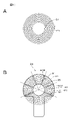
- the positive current collector 24 may be a positive current collector 51 .
- the positive electrode current collector plate 51 has a substantially circular base portion 51A having a hole 51B in the center and a strip portion 51C extending outward from a portion of the outer edge of the base portion 51A.
- eight welded portion groups 81 are radially formed. Further, for example, as shown in FIG.
- the positive current collecting plate 24 may be a positive current collecting plate 52 .
- the positive electrode current collector plate 52 has a substantially circular base portion 52A having a hole 52B in the center and a strip portion 52C extending outward from a part of the outer edge of the base portion 52A. Inward notches 52D and 52E are formed between the base portion 52A and the belt-like portion 52C (at two locations).
- the shape of the positive electrode current collector plate is the shape of the positive electrode current collector plate 52, for example, as shown in FIG. 17B, six welded portion groups 81 are radially formed.
- the above modified examples can also be applied to the negative electrode current collector plate 25 .
- Laser welding may be performed by intermittently irradiating laser light.
- the shape of the welded portion group, the number of welded portions constituting the welded portion group, and the like can be changed as appropriate.
- the configuration in which the second negative electrode active material uncovered portion 221B and the third negative electrode active material uncovered portion 221C are provided is preferable, but the present invention is also applicable to a lithium ion battery without these. be able to.
- the number of the grooves 43 is eight in the above-described embodiment and comparative example, the number may be other than this.
- a configuration in which grooves 43 are provided is preferable, but the present invention is also applicable to batteries without grooves 43 .
- the battery size may be a size other than 21700 (diameter 21 mm, height 70 mm) and 18650 (diameter 18 mm, height 65 mm).
- the shape of the fan-shaped portions 31 and 33 according to the embodiment described above may be a shape other than the fan-shaped shape.
- the present invention can be applied to batteries other than lithium ion batteries and batteries other than cylindrical batteries (for example, laminate type batteries, square batteries, coin type batteries, button type batteries). is also possible.
- the shape of the "end surface of the wound electrode" may be not only cylindrical but also rectangular, elliptical, or flat.
- the present invention can also be implemented as a method for manufacturing a battery.
- FIG. 18 is a block diagram showing a circuit configuration example when the secondary battery according to the embodiment or example of the present invention is applied to the battery pack 300.
- the battery pack 300 includes an assembled battery 301 , a switch section 304 including a charge control switch 302 a and a discharge control switch 303 a , a current detection resistor 307 , a temperature detection element 308 and a control section 310 .
- the control unit 310 can control each device, control charging/discharging when abnormal heat is generated, and calculate and correct the remaining capacity of the battery pack 300 .
- a positive terminal 321 and a negative terminal 322 of the battery pack 300 are connected to a charger or an electronic device, and charging and discharging are performed.
- the assembled battery 301 is formed by connecting a plurality of secondary batteries 301a in series and/or in parallel.
- FIG. 18 shows an example in which six secondary batteries 301a are connected in two parallel three series (2P3S).
- the secondary battery of the present invention can be applied to the secondary battery 301a.
- the temperature detection unit 318 is connected to a temperature detection element 308 (eg, a thermistor), measures the temperature of the assembled battery 301 or the battery pack 300, and supplies the measured temperature to the control unit 310.
- the voltage detection unit 311 measures the voltage of the assembled battery 301 and the secondary batteries 301 a that constitute it, A/D-converts the measured voltage, and supplies it to the control unit 310 .
- a current measurement unit 313 measures current using a current detection resistor 307 and supplies the measured current to the control unit 310 .
- the switch control section 314 controls the charge control switch 302a and the discharge control switch 303a of the switch section 304 based on the voltage and current input from the voltage detection section 311 and the current measurement section 313.
- the switch control unit 314 controls the switch unit 304 when the secondary battery 301a reaches the overcharge detection voltage (for example, 4.20V ⁇ 0.05V) or higher or the overdischarge detection voltage (2.4V ⁇ 0.1V) or lower. Overcharge or overdischarge is prevented by sending an OFF control signal to .
- the charge control switch 302a or the discharge control switch 303a After the charge control switch 302a or the discharge control switch 303a is turned off, charging or discharging is possible only through the diode 302b or the diode 303b.
- Semiconductor switches such as MOSFETs can be used for these charge/discharge switches.
- the switch unit 304 is provided on the + side in FIG. 18, but may be provided on the - side.
- the memory 317 consists of RAM and ROM, and stores and rewrites the values of the battery characteristics calculated by the control unit 310, the full charge capacity, the remaining capacity, and the like.
- the secondary battery according to the embodiment or example of the present invention described above can be mounted on devices such as electronic devices, electric transportation devices, and power storage devices, and used to supply electric power.
- Examples of electronic devices include notebook computers, smartphones, tablet terminals, PDAs (personal digital assistants), mobile phones, wearable terminals, digital still cameras, e-books, music players, game machines, hearing aids, power tools, televisions, and lighting equipment. , toys, medical devices, and robots. In a broad sense, electronic devices also include electric transportation equipment, power storage devices, power tools, and electric unmanned aerial vehicles, which will be described later.
- Electric transportation equipment includes electric vehicles (including hybrid vehicles), electric motorcycles, electrically assisted bicycles, electric buses, electric carts, automated guided vehicles (AGV), and railway vehicles. It also includes electric passenger aircraft and electric unmanned aerial vehicles for transportation.
- the secondary battery according to the present invention can be used not only as a driving power source, but also as an auxiliary power source, an energy regeneration power source, and the like.
- power storage devices include power storage modules for commercial or domestic use, power storage power sources for buildings such as houses, buildings, and offices, or for power generation equipment.
- the electric driver 431 is provided with a motor 433 that transmits rotational power to a shaft 434 and a trigger switch 432 that is operated by a user.
- a battery pack 430 and a motor control unit 435 are accommodated in a lower housing of the handle of the electric driver 431 .
- the battery pack 430 is built into the electric driver 431 or is detachable therefrom.
- the secondary battery of the present invention can be applied to the batteries forming battery pack 430 .
- Each of the battery pack 430 and the motor control unit 435 may be provided with a microcomputer (not shown) so that charge/discharge information of the battery pack 430 can be communicated with each other.
- the motor control unit 435 can control the operation of the motor 433 and cut off the power supply to the motor 433 in the event of an abnormality such as overdischarge.
- FIG. 20 schematically shows a configuration example of a hybrid vehicle (HV) employing a series hybrid system.
- a series hybrid system is a vehicle that runs with a power driving force conversion device using power generated by a generator driven by an engine or power temporarily stored in a battery.
- This hybrid vehicle 600 includes an engine 601, a generator 602, a power driving force conversion device (DC motor or AC motor, hereinafter simply referred to as "motor 603"), driving wheels 604a, driving wheels 604b, wheels 605a, wheels 605b, A battery 608, a vehicle control device 609, various sensors 610, and a charging port 611 are mounted.
- the battery 608 the secondary battery of the present invention or a power storage module equipped with a plurality of secondary batteries of the present invention can be applied.
- the electric power of the battery 608 operates the motor 603, and the rotational force of the motor 603 is transmitted to the driving wheels 604a and 604b.
- the rotational power produced by engine 601 allows power generated by generator 602 to be stored in battery 608 .
- Various sensors 610 control the engine speed via the vehicle control device 609 and control the opening of a throttle valve (not shown).
- HV plug-in hybrid vehicles
- the secondary battery according to the present invention can be applied to a miniaturized primary battery and use it as a power supply for the tire pressure monitoring system (TPMS) built into the wheels 604 and 605.
- TPMS tire pressure monitoring system
- the present invention can also be applied to a parallel system that uses both an engine and a motor, or a hybrid vehicle that combines a series system and a parallel system. Furthermore, the present invention can also be applied to an electric vehicle (EV or BEV) that runs only with a drive motor that does not use an engine, or a fuel cell vehicle (FCV).
- EV or BEV electric vehicle
- FCV fuel cell vehicle
- SYMBOLS 1 Lithium ion battery, 12, 13... Insulating plate, 21... Positive electrode, 21A... Positive electrode foil, 21B... Positive electrode active material layer, 21C... Positive electrode active material non-covering part, 22... Negative electrode, 22A... Negative electrode foil, 22B... Negative electrode active material layer, 22C... Negative electrode active material uncoated portion, 23... Separator, 24... Positive electrode collector plate, 25.
- Negative electrode current collector 26 Through hole 31, 33 Fan-shaped portion 32, 34 Band-shaped portion 41, 42 End surface 43 Groove 71, 72 Flat surfaces 81, 82 Welded portion group 81A First welded portion 81B Second welded portion 82A Third welded portion 82B Third 4 welded portion, 221A... first negative electrode active material non-coated portion
Abstract
Description
セパレータを介して帯状の正極と帯状の負極とが積層された構造を有する電極巻回体と、正極集電板及び負極集電板とが、電池缶に収容された二次電池であって、
正極は、帯状の正極箔上に、正極活物質層が被覆された正極活物質被覆部と、正極活物質非被覆部とを有し、
負極は、帯状の負極箔上に、負極活物質層が被覆された負極活物質被覆部と、負極箔の長手方向に延在する負極活物質非被覆部とを有し、
正極活物質非被覆部は、電極巻回体の端面の一方において、正極集電板と溶接されており、
負極活物質非被覆部は、電極巻回体の端部の他方において、負極集電板と溶接されており、
正極集電板及び負極集電板は、放射状に形成された溶接部群をそれぞれ有し、
正極活物質非被覆部は、正極箔の巻き終わり端部から最も近い第1の溶接部と、当該第1の溶接部の次に巻き終わり端部に近い第2の溶接部とを有し、
負極活物質非被覆部は、負極箔の巻き終わり端部から最も近い第3の溶接部と、当該第3の溶接部の次に巻き終わり端部に近い第4の溶接部とを有し、
正極箔の巻き終わり端部から第1の溶接部までの距離をLC1(mm)、第1の溶接部から第2の溶接部までの距離をLC2(mm)とし、
負極箔の巻き終わり端部から第3の溶接部までの距離をLA1(mm)、第3の溶接部から第4の溶接部までの距離をLA2(mm)とした場合に、下記式(1)及び式(2)を満たす二次電池である。
0≦LC1≦LC2・・・(1)
0≦LA1≦LA2・・・(2)
<一実施形態>
<変形例>
<応用例>
以下に説明する実施形態等は本発明の好適な具体例であり、本発明の内容がこれらの実施形態等に限定されるものではない。なお、説明の理解を容易とするために、各図における一部の構成を拡大、強調したり、若しくは縮小したり、一部の図示を簡略化する場合もある。
[リチウムイオン電池の構成例]
本発明の実施形態では、二次電池として、円筒形状のリチウムイオン電池を例にして説明する。図1~図9を参照しつつ、一実施形態に係るリチウムイオン電池(リチウムイオン電池1)の構成例に関して説明する。図1は、リチウムイオン電池1の概略断面図である。リチウムイオン電池1は、例えば、図1に示すように、電池缶11の内部に電極巻回体20が収納されている円筒型のリチウムイオン電池1である。なお、以下の説明において、特に断らない限り、図1の紙面に向かって水平方向をX軸方向、奥行方向をY軸方向、垂直方向(リチウムイオン電池1の中心軸(巻回軸とも適宜、称し、図1において一点鎖線で示される軸))の延在方向)をZ軸方向と適宜、称する。
電池缶11は、主に、電極巻回体20を収納する部材である。この電池缶11は、例えば、一端面が開放されると共に他端面が閉塞された円筒状の容器である。すなわち、電池缶11は、開放された一端面(開放端面11N)を有している。この電池缶11は、例えば、鉄、アルミニウム及びそれらの合金などの金属材料のうちのいずれか1種類又は2種類以上を含んでいる。電池缶11の表面に、例えば、ニッケルなどの金属材料のうちのいずれか1種類又は2種類以上が鍍金されていてもよい。
絶縁板12,13は、電極巻回体20の中心軸(電極巻回体20の端面の略中心を通り図1のZ軸と平行な方向)に対して略垂直な面を有する円板状の板である。また、絶縁板12,13は、例えば、互いに電極巻回体20を挟むように配置されている。
電池缶11の開放端面11Nには、電池蓋14及び安全弁機構30がガスケット15を介してかしめられており、かしめ構造11R(クリンプ構造)が形成されている。これにより、電池缶11の内部に電極巻回体20などが収納された状態において、その電池缶11は密閉されている。
電池蓋14は、主に、電池缶11の内部に電極巻回体20などが収納された状態において、その電池缶11の開放端面11Nを閉塞する部材である。この電池蓋14は、例えば、電池缶11の形成材料と同様の材料を含んでいる。電池蓋14のうちの中央領域は、例えば、+Z方向に突出している。これにより、電池蓋14のうちの中央領域以外の領域(周辺領域)は、例えば、安全弁機構30に接触している。
ガスケット15は、主に、電池缶11(折り曲げ部11P)と電池蓋14との間に介在することにより、その折り曲げ部11Pと電池蓋14との間の隙間を封止する部材である。ガスケット15の表面に、例えば、アスファルトなどが塗布されていてもよい。
安全弁機構30は、主に、電池缶11の内部の圧力(内圧)が上昇した際に、必要に応じて電池缶11の密閉状態を解除することにより、その内圧を開放する。電池缶11の内圧が上昇する原因は、例えば、充放電時において電解液の分解反応に起因して発生するガスなどである。
円筒形状のリチウムイオン電池1では、帯状の正極21と帯状の負極22とがセパレータ23を挟んで積層され、且つ、渦巻き状に巻回されて電解液に含浸された状態で、電池缶11に収まっている。正極21は正極箔21Aの片面又は両面に正極活物質層21Bを形成したものであり、正極箔21Aの材料は例えば、アルミニウムやアルミニウム合金でできた金属箔である。負極22は負極箔22Aの片面又は両面に負極活物質層22Bを形成したものであり、負極箔22Aの材料は例えば、ニッケル、ニッケル合金、銅や銅合金でできた金属箔である。セパレータ23は多孔質で絶縁性のあるフィルムであり、正極21と負極22とを電気的に絶縁しながら、イオンや電解液等の物質の移動を可能にしている。
通常のリチウムイオン電池では例えば、正極と負極との一か所ずつに電流取出し用のリードが溶接されているが、これでは電池の内部抵抗が大きく、放電時にリチウムイオン電池が発熱し高温になるため、ハイレート放電には適さない。そこで、本実施形態のリチウムイオン電池1では、電極巻回体20の一方の端面である端面41に正極集電板24を配置し、電極巻回体20の他方の端面である端面42に負極集電板25を配置する。そして、正極集電板24と端面41に存在する正極活物質非被覆部21Cとを多点で溶接し、また、負極集電板25と端面42に存在する負極活物質非被覆部22C(具体的には第1の負極活物質非被覆部221A)とを多点で溶接することで、リチウムイオン電池1の内部抵抗を低く抑え、ハイレート放電を可能としている。
正極活物質層21Bは、リチウムを吸蔵及び放出することが可能である正極材料(正極活物質)を少なくとも含み、さらに、正極結着剤及び正極導電剤などを含んでいてもよい。正極材料は、リチウム含有複合酸化物又はリチウム含有リン酸化合物が好ましい。リチウム含有複合酸化物は、例えば、層状岩塩型又はスピネル型の結晶構造を有している。リチウム含有リン酸化合物は、例えば、オリビン型の結晶構造を有している。
負極22を構成する負極箔22Aの表面は、負極活物質層22Bとの密着性向上のために粗面化されていることが好ましい。負極活物質層22Bは、リチウムを吸蔵及び放出することが可能である負極材料(負極活物質)を少なくとも含み、さらに、負極結着剤及び負極導電剤などを含んでいてもよい。
セパレータ23は、樹脂を含む多孔質膜であり、2種類以上の多孔質膜の積層膜でもよい。樹脂は、ポリプロピレン及びポリエチレンなどである。セパレータ23は、多孔質膜を基材層として、その片面又は両面に樹脂層を含んでいてもよい。正極21及び負極22のそれぞれに対するセパレータ23の密着性が向上するため、電極巻回体20の歪みが抑制されるからである。
電解液は、溶媒及び電解質塩を含み、必要に応じてさらに添加剤などを含んでいてもよい。溶媒は、有機溶媒などの非水溶媒、又は水である。非水溶媒を含む電解液を非水電解液という。非水溶媒は、環状炭酸エステル、鎖状炭酸エステル、ラクトン、鎖状カルボン酸エステル又はニトリル(モノニトリル)などである。
次に、上述した構成を有するリチウムイオン電池1における溶接構造の一例について説明する。リチウムイオン電池1では、略円筒形状を有する電極巻回体20の端面41に正極活物質非被覆部21Cが露出して、端面42に第1の負極活物質非被覆部221Aが露出している。端面41に正極活物質非被覆部21Cが露出している側を電極巻回体20の正極側と適宜、称する。端面42に第1の負極活物質非被覆部221Aが露出している側を電極巻回体20の負極側と称する。
0≦LC1≦LC2・・・(1)
0≦LA1≦LA2・・・(2)
次に、図15Aから図15Fを参照して、本実施形態に係るリチウムイオン電池1の作製方法について説明する。まず、正極活物質を、帯状の正極箔21Aの表面に塗着させ、これを正極活物質被覆部21Bとし、負極活物質を、帯状の負極箔22Aの表面に塗着させ、これを負極活物質被覆部22Bとした。このとき、正極箔21Aの幅方向の一端側に正極活物質が塗着されていない正極活物質非被覆部21Cを設け、負極箔22Aに、負極活物質が塗着されていない負極活物質非被覆部22C(第1の負極活物質非被覆部221A、第2の負極活物質非被覆部221B及び第3の負極活物質非被覆部221C)を設けた。次に、正極21と負極22とに対して乾燥等の工程を行った。そして、正極活物質非被覆部21Cと負極活物質非被覆部22Cとが逆方向となるようにセパレータ23を介して重ね、中心軸に貫通孔26ができるように渦巻き状に巻回して、図15Aのような電極巻回体20を作製した。
本実施形態によれば、例えば、下記の効果を得ることができる。
正極21の巻き終わり端部F1及び負極22の巻き終わり端部F1からのそれぞれに近い箇所に溶接部を設けることにより集電効率を向上させることができる。したがって、電池の内部抵抗が小さく、高出力特性の優れたリチウムイオン電池を提供できる。
セパレータ23を正極活物質被覆部21Bと負極活物質被覆部22Bの全範囲を覆うように重ねた。また、溝43の数を8とし略等角間隔となるように配置した。
リチウムイオン電池1を上述した工程により作製した。この際、0≦LC1≦LC2を満たすように第1の溶接部81A及び第2の溶接部81Bを設け、且つ、0≦LA1≦LA2を満たすように第3の溶接部82A及び第4の溶接部82Bを設けた。
LC1とLC2との関係がLC2<LC1となるように第1の溶接部81A及び第2の溶接部81Bを設け、LA1とLA2との関係がLA2<LA1となるように第3の溶接部82A及び第4の溶接部82Bを設けた。その他は、実施例1と同様にリチウムイオン電池を作製した。
比較例2では、0≦LC1≦LC2を満たすように第1の溶接部81A及び第2の溶接部81Bを設け、且つ、0≦LA1≦LA2を満たさないように、換言すれば、LA2<LA1となるように第3の溶接部82A及び第4の溶接部82Bを設けた。その他は、実施例1と同様にリチウムイオン電池を作製した。
比較例3では、0≦LC1≦LC2を満たさないように、換言すれば、LC2<LC1となるように第1の溶接部81A及び第2の溶接部81Bを設け、0≦LA1≦LA2を満たすように第3の溶接部82A及び第4の溶接部82Bを設けた。その他は、実施例1と同様にリチウムイオン電池を作製した。
実施例1及び比較例1~3の電池に対して、交流抵抗ACR(mΩ)、直流抵抗DCR(mΩ)、及び負荷放電率(%)を測定した。
交流抵抗ACRは、交流1kHzでの抵抗値(mΩ)を測定した。
直流抵抗DCR(mΩ)は、放電電流を5秒間で0(A)から100(A)まで上昇させたときの電圧の傾きを算出することで得た。
負荷放電率(%)については、定電流2(A)で3.5(h)充電した後に、40(A)の電流値、カットオフ電圧が2.0(V)、環境温度23℃で放電し、電池の表面温度が75℃に到達するまでの放電容量(mAh)を充電容量(mAh)で除することで得た。
それぞれの測定において、10本のリチウムイオン電池の測定値から平均値を算出した。
結果を表1に示す。

以上、本発明の一実施形態について具体的に説明したが、本発明の内容は上述した実施形態に限定されるものではなく、本発明の技術的思想に基づく各種の変形が可能である。
上述した実施形態において、第2の負極活物質非被覆部221B及び第3の負極活物質非被覆部221Cが設けられる構成が好ましいが、これらが無いリチウムイオン電池に対しても本発明を適用することができる。
上述した実施例及び比較例では、溝43の数を8としていたが、これ以外の数であってもよい。溝43が設けられる構成が好ましいが、本発明は、溝43がない電池にも適用可能である。電池サイズは、21700(直径21mm,高さ70mm)や18650(直径18mm,高さ65mm)以外のサイズであってもよい。
上述した実施形態に係る扇状部31,33の形状は、扇形の形状以外の形状であってもよい。
(1)電池パック
図18は、本発明の実施形態又は実施例に係る二次電池を電池パック300に適用した場合の回路構成例を示すブロック図である。電池パック300は、組電池301、充電制御スイッチ302aと、放電制御スイッチ303a、を備えるスイッチ部304、電流検出抵抗307、温度検出素子308、制御部310を備えている。制御部310は各デバイスの制御を行い、さらに異常発熱時に充放電制御を行ったり、電池パック300の残容量の算出や補正を行ったりすることが可能である。電池パック300の正極端子321及び負極端子322は、充電器や電子機器に接続され、充放電が行われる。
上述した本発明の実施形態又は実施例に係る二次電池は、電子機器や電動輸送機器、蓄電装置などの機器に搭載され、電力を供給するために使用することができる。
図19を参照して、本発明が適用可能な電動工具として電動ドライバの例について概略的に説明する。電動ドライバ431には、シャフト434に回転動力を伝達するモータ433と、ユーザが操作するトリガースイッチ432が設けられている。電動ドライバ431の把手の下部筐体内に、電池パック430及びモータ制御部435が収納されている。電池パック430は、電動ドライバ431に対して内蔵されているか、又は着脱自在とされている。電池パック430を構成する電池に対して、本発明の二次電池を適用可能である。
本発明を電動車両用の蓄電システムに適用した例として、図20に、シリーズハイブリッドシステムを採用したハイブリッド車両(HV)の構成例を概略的に示す。シリーズハイブリッドシステムはエンジンを動力とする発電機で発電された電力、あるいはそれをバッテリに一旦貯めておいた電力を用いて、電力駆動力変換装置で走行する車である。
Claims (7)
- セパレータを介して帯状の正極と帯状の負極とが積層された電極巻回体と、正極集電板及び負極集電板とが、電池缶に収容された二次電池であって、
前記正極は、帯状の正極箔上に、正極活物質層が被覆された正極活物質被覆部と、正極活物質非被覆部とを有し、
前記負極は、帯状の負極箔上に、負極活物質層が被覆された負極活物質被覆部と、前記負極箔の長手方向に延在する負極活物質非被覆部とを有し、
前記正極活物質非被覆部は、前記電極巻回体の端面の一方において、前記正極集電板と溶接されており、
前記負極活物質非被覆部は、前記電極巻回体の端面の他方において、前記負極集電板と溶接されており、
前記正極集電板及び前記負極集電板は、放射状に形成された溶接部群をそれぞれ有し、
前記正極活物質非被覆部は、前記正極箔の巻き終わり端部から最も近い第1の溶接部と、当該第1の溶接部の次に前記巻き終わり端部に近い第2の溶接部とを有し、
前記負極活物質非被覆部は、前記負極箔の巻き終わり端部から最も近い第3の溶接部と、当該第3の溶接部の次に前記巻き終わり端部に近い第4の溶接部とを有し、
前記正極箔の巻き終わり端部から前記第1の溶接部までの距離をLC1(mm)、前記第1の溶接部から前記第2の溶接部までの距離をLC2(mm)とし、
前記負極箔の巻き終わり端部から前記第3の溶接部までの距離をLA1(mm)、前記第3の溶接部から前記第4の溶接部までの距離をLA2(mm)とした場合に、下記式(1)及び式(2)を満たす二次電池。
0≦LC1≦LC2・・・(1)
0≦LA1≦LA2・・・(2) - 前記二次電池の直径をD(mm)とした場合に、
前記LC1及び前記LA1の上限値が0.38Dであり、前記LC2及び前記LA2の上限値が0.75Dである
請求項1に記載の二次電池。 - 前記正極活物質非被覆部が折れ曲がることにより正極側平坦面が形成され、当該正極側平坦面と前記正極集電板とが溶接されており、
前記負極活物質非被覆部が折れ曲がることにより負極側平坦面が形成され、当該負極側平坦面と前記負極集電板とが溶接されている
請求項1又は2に記載の二次電池。 - 前記正極集電板は、正極側扇状部と正極側帯状部とを有し、前記正極側扇状部と前記正極側平坦面とが溶接されており、
前記負極集電板は、負極側扇状部と負極側帯状部とを有し、前記負極側扇状部と前記負極側平坦面とが溶接されている
請求項3に記載の二次電池。 - 前記正極側平坦面及び前記負極側平坦面のそれぞれが溝を有している
請求項3又は4に記載の二次電池。 - 請求項1から5までの何れかに記載の二次電池を有する電子機器。
- 請求項1から5までの何れかに記載の二次電池を有する電動工具。
Priority Applications (3)
| Application Number | Priority Date | Filing Date | Title |
|---|---|---|---|
| JP2022579434A JPWO2022168622A1 (ja) | 2021-02-02 | 2022-01-20 | |
| CN202280011686.7A CN116802918A (zh) | 2021-02-02 | 2022-01-20 | 二次电池、电子设备及电动工具 |
| US18/216,158 US20230344093A1 (en) | 2021-02-02 | 2023-06-29 | Secondary battery, electronic equipment, and electric tool |
Applications Claiming Priority (2)
| Application Number | Priority Date | Filing Date | Title |
|---|---|---|---|
| JP2021-014833 | 2021-02-02 | ||
| JP2021014833 | 2021-02-02 |
Related Child Applications (1)
| Application Number | Title | Priority Date | Filing Date |
|---|---|---|---|
| US18/216,158 Continuation US20230344093A1 (en) | 2021-02-02 | 2023-06-29 | Secondary battery, electronic equipment, and electric tool |
Publications (1)
| Publication Number | Publication Date |
|---|---|
| WO2022168622A1 true WO2022168622A1 (ja) | 2022-08-11 |
Family
ID=82740627
Family Applications (1)
| Application Number | Title | Priority Date | Filing Date |
|---|---|---|---|
| PCT/JP2022/002023 WO2022168622A1 (ja) | 2021-02-02 | 2022-01-20 | 二次電池、電子機器及び電動工具 |
Country Status (4)
| Country | Link |
|---|---|
| US (1) | US20230344093A1 (ja) |
| JP (1) | JPWO2022168622A1 (ja) |
| CN (1) | CN116802918A (ja) |
| WO (1) | WO2022168622A1 (ja) |
Citations (3)
| Publication number | Priority date | Publication date | Assignee | Title |
|---|---|---|---|---|
| JP2007227292A (ja) * | 2006-02-27 | 2007-09-06 | Sanyo Electric Co Ltd | 円筒形電池およびその製造方法 |
| JP2007335156A (ja) * | 2006-06-13 | 2007-12-27 | Honda Motor Co Ltd | 蓄電素子 |
| JP2009277643A (ja) * | 2008-01-28 | 2009-11-26 | Panasonic Corp | 二次電池用集電端子板、二次電池および二次電池の製造方法 |
-
2022
- 2022-01-20 CN CN202280011686.7A patent/CN116802918A/zh active Pending
- 2022-01-20 WO PCT/JP2022/002023 patent/WO2022168622A1/ja active Application Filing
- 2022-01-20 JP JP2022579434A patent/JPWO2022168622A1/ja active Pending
-
2023
- 2023-06-29 US US18/216,158 patent/US20230344093A1/en active Pending
Patent Citations (3)
| Publication number | Priority date | Publication date | Assignee | Title |
|---|---|---|---|---|
| JP2007227292A (ja) * | 2006-02-27 | 2007-09-06 | Sanyo Electric Co Ltd | 円筒形電池およびその製造方法 |
| JP2007335156A (ja) * | 2006-06-13 | 2007-12-27 | Honda Motor Co Ltd | 蓄電素子 |
| JP2009277643A (ja) * | 2008-01-28 | 2009-11-26 | Panasonic Corp | 二次電池用集電端子板、二次電池および二次電池の製造方法 |
Also Published As
| Publication number | Publication date |
|---|---|
| US20230344093A1 (en) | 2023-10-26 |
| JPWO2022168622A1 (ja) | 2022-08-11 |
| CN116802918A (zh) | 2023-09-22 |
Similar Documents
| Publication | Publication Date | Title |
|---|---|---|
| JP7251686B2 (ja) | 二次電池、電子機器及び電動工具 | |
| JP7428235B2 (ja) | 二次電池、電子機器及び電動工具 | |
| US20220149490A1 (en) | Secondary battery, battery pack, electronic device, electric tool, and electric vehicle | |
| JP7298691B2 (ja) | 二次電池、電池パック、電子機器、電動工具、電動式航空機及び電動車両 | |
| US20220344724A1 (en) | Secondary battery, electronic device, and power tool | |
| WO2022168623A1 (ja) | 二次電池、電子機器及び電動工具 | |
| JP7405239B2 (ja) | 二次電池、電子機器及び電動工具 | |
| JP7380825B2 (ja) | 二次電池、電子機器及び電動工具 | |
| WO2022168622A1 (ja) | 二次電池、電子機器及び電動工具 | |
| CN114223079A (zh) | 二次电池、电池组、电子设备、电动工具以及电动车辆 | |
| JP7409398B2 (ja) | 二次電池、電子機器及び電動工具 | |
| JP7416095B2 (ja) | 二次電池、電子機器及び電動工具 | |
| JP7290173B2 (ja) | 二次電池、二次電池の製造方法、電子機器、電動工具 | |
| WO2022153647A1 (ja) | 二次電池、電子機器及び電動工具 | |
| WO2022163049A1 (ja) | 二次電池、電子機器及び電動工具 | |
| WO2022163480A1 (ja) | 二次電池、電子機器及び電動工具 | |
| JP7371701B2 (ja) | 二次電池、電子機器及び電動工具 | |
| WO2022163479A1 (ja) | 二次電池、電子機器及び電動工具 | |
| WO2022163482A1 (ja) | 二次電池、電子機器及び電動工具 | |
| WO2022054642A1 (ja) | 二次電池、電子機器及び電動工具 | |
| JP7332032B2 (ja) | 二次電池、電子機器及び電動工具 |
Legal Events
| Date | Code | Title | Description |
|---|---|---|---|
| 121 | Ep: the epo has been informed by wipo that ep was designated in this application |
Ref document number: 22749497 Country of ref document: EP Kind code of ref document: A1 |
|
| ENP | Entry into the national phase |
Ref document number: 2022579434 Country of ref document: JP Kind code of ref document: A |
|
| WWE | Wipo information: entry into national phase |
Ref document number: 202280011686.7 Country of ref document: CN |
|
| NENP | Non-entry into the national phase |
Ref country code: DE |
|
| 122 | Ep: pct application non-entry in european phase |
Ref document number: 22749497 Country of ref document: EP Kind code of ref document: A1 |