WO2016171273A1 - 被覆金型およびその製造方法 - Google Patents
被覆金型およびその製造方法 Download PDFInfo
- Publication number
- WO2016171273A1 WO2016171273A1 PCT/JP2016/062828 JP2016062828W WO2016171273A1 WO 2016171273 A1 WO2016171273 A1 WO 2016171273A1 JP 2016062828 W JP2016062828 W JP 2016062828W WO 2016171273 A1 WO2016171273 A1 WO 2016171273A1
- Authority
- WO
- WIPO (PCT)
- Prior art keywords
- layer
- film
- mold
- coating
- nitride
- Prior art date
Links
Images


Classifications
-
- C—CHEMISTRY; METALLURGY
- C23—COATING METALLIC MATERIAL; COATING MATERIAL WITH METALLIC MATERIAL; CHEMICAL SURFACE TREATMENT; DIFFUSION TREATMENT OF METALLIC MATERIAL; COATING BY VACUUM EVAPORATION, BY SPUTTERING, BY ION IMPLANTATION OR BY CHEMICAL VAPOUR DEPOSITION, IN GENERAL; INHIBITING CORROSION OF METALLIC MATERIAL OR INCRUSTATION IN GENERAL
- C23C—COATING METALLIC MATERIAL; COATING MATERIAL WITH METALLIC MATERIAL; SURFACE TREATMENT OF METALLIC MATERIAL BY DIFFUSION INTO THE SURFACE, BY CHEMICAL CONVERSION OR SUBSTITUTION; COATING BY VACUUM EVAPORATION, BY SPUTTERING, BY ION IMPLANTATION OR BY CHEMICAL VAPOUR DEPOSITION, IN GENERAL
- C23C14/00—Coating by vacuum evaporation, by sputtering or by ion implantation of the coating forming material
- C23C14/06—Coating by vacuum evaporation, by sputtering or by ion implantation of the coating forming material characterised by the coating material
- C23C14/0641—Nitrides
-
- B—PERFORMING OPERATIONS; TRANSPORTING
- B21—MECHANICAL METAL-WORKING WITHOUT ESSENTIALLY REMOVING MATERIAL; PUNCHING METAL
- B21D—WORKING OR PROCESSING OF SHEET METAL OR METAL TUBES, RODS OR PROFILES WITHOUT ESSENTIALLY REMOVING MATERIAL; PUNCHING METAL
- B21D37/00—Tools as parts of machines covered by this subclass
- B21D37/01—Selection of materials
-
- B—PERFORMING OPERATIONS; TRANSPORTING
- B21—MECHANICAL METAL-WORKING WITHOUT ESSENTIALLY REMOVING MATERIAL; PUNCHING METAL
- B21J—FORGING; HAMMERING; PRESSING METAL; RIVETING; FORGE FURNACES
- B21J13/00—Details of machines for forging, pressing, or hammering
- B21J13/02—Dies or mountings therefor
-
- C—CHEMISTRY; METALLURGY
- C23—COATING METALLIC MATERIAL; COATING MATERIAL WITH METALLIC MATERIAL; CHEMICAL SURFACE TREATMENT; DIFFUSION TREATMENT OF METALLIC MATERIAL; COATING BY VACUUM EVAPORATION, BY SPUTTERING, BY ION IMPLANTATION OR BY CHEMICAL VAPOUR DEPOSITION, IN GENERAL; INHIBITING CORROSION OF METALLIC MATERIAL OR INCRUSTATION IN GENERAL
- C23C—COATING METALLIC MATERIAL; COATING MATERIAL WITH METALLIC MATERIAL; SURFACE TREATMENT OF METALLIC MATERIAL BY DIFFUSION INTO THE SURFACE, BY CHEMICAL CONVERSION OR SUBSTITUTION; COATING BY VACUUM EVAPORATION, BY SPUTTERING, BY ION IMPLANTATION OR BY CHEMICAL VAPOUR DEPOSITION, IN GENERAL
- C23C14/00—Coating by vacuum evaporation, by sputtering or by ion implantation of the coating forming material
- C23C14/02—Pretreatment of the material to be coated
- C23C14/021—Cleaning or etching treatments
- C23C14/022—Cleaning or etching treatments by means of bombardment with energetic particles or radiation
-
- C—CHEMISTRY; METALLURGY
- C23—COATING METALLIC MATERIAL; COATING MATERIAL WITH METALLIC MATERIAL; CHEMICAL SURFACE TREATMENT; DIFFUSION TREATMENT OF METALLIC MATERIAL; COATING BY VACUUM EVAPORATION, BY SPUTTERING, BY ION IMPLANTATION OR BY CHEMICAL VAPOUR DEPOSITION, IN GENERAL; INHIBITING CORROSION OF METALLIC MATERIAL OR INCRUSTATION IN GENERAL
- C23C—COATING METALLIC MATERIAL; COATING MATERIAL WITH METALLIC MATERIAL; SURFACE TREATMENT OF METALLIC MATERIAL BY DIFFUSION INTO THE SURFACE, BY CHEMICAL CONVERSION OR SUBSTITUTION; COATING BY VACUUM EVAPORATION, BY SPUTTERING, BY ION IMPLANTATION OR BY CHEMICAL VAPOUR DEPOSITION, IN GENERAL
- C23C14/00—Coating by vacuum evaporation, by sputtering or by ion implantation of the coating forming material
- C23C14/02—Pretreatment of the material to be coated
- C23C14/028—Physical treatment to alter the texture of the substrate surface, e.g. grinding, polishing
-
- C—CHEMISTRY; METALLURGY
- C23—COATING METALLIC MATERIAL; COATING MATERIAL WITH METALLIC MATERIAL; CHEMICAL SURFACE TREATMENT; DIFFUSION TREATMENT OF METALLIC MATERIAL; COATING BY VACUUM EVAPORATION, BY SPUTTERING, BY ION IMPLANTATION OR BY CHEMICAL VAPOUR DEPOSITION, IN GENERAL; INHIBITING CORROSION OF METALLIC MATERIAL OR INCRUSTATION IN GENERAL
- C23C—COATING METALLIC MATERIAL; COATING MATERIAL WITH METALLIC MATERIAL; SURFACE TREATMENT OF METALLIC MATERIAL BY DIFFUSION INTO THE SURFACE, BY CHEMICAL CONVERSION OR SUBSTITUTION; COATING BY VACUUM EVAPORATION, BY SPUTTERING, BY ION IMPLANTATION OR BY CHEMICAL VAPOUR DEPOSITION, IN GENERAL
- C23C14/00—Coating by vacuum evaporation, by sputtering or by ion implantation of the coating forming material
- C23C14/06—Coating by vacuum evaporation, by sputtering or by ion implantation of the coating forming material characterised by the coating material
- C23C14/0605—Carbon
- C23C14/0611—Diamond
-
- C—CHEMISTRY; METALLURGY
- C23—COATING METALLIC MATERIAL; COATING MATERIAL WITH METALLIC MATERIAL; CHEMICAL SURFACE TREATMENT; DIFFUSION TREATMENT OF METALLIC MATERIAL; COATING BY VACUUM EVAPORATION, BY SPUTTERING, BY ION IMPLANTATION OR BY CHEMICAL VAPOUR DEPOSITION, IN GENERAL; INHIBITING CORROSION OF METALLIC MATERIAL OR INCRUSTATION IN GENERAL
- C23C—COATING METALLIC MATERIAL; COATING MATERIAL WITH METALLIC MATERIAL; SURFACE TREATMENT OF METALLIC MATERIAL BY DIFFUSION INTO THE SURFACE, BY CHEMICAL CONVERSION OR SUBSTITUTION; COATING BY VACUUM EVAPORATION, BY SPUTTERING, BY ION IMPLANTATION OR BY CHEMICAL VAPOUR DEPOSITION, IN GENERAL
- C23C14/00—Coating by vacuum evaporation, by sputtering or by ion implantation of the coating forming material
- C23C14/22—Coating by vacuum evaporation, by sputtering or by ion implantation of the coating forming material characterised by the process of coating
- C23C14/24—Vacuum evaporation
- C23C14/32—Vacuum evaporation by explosion; by evaporation and subsequent ionisation of the vapours, e.g. ion-plating
- C23C14/325—Electric arc evaporation
-
- C—CHEMISTRY; METALLURGY
- C23—COATING METALLIC MATERIAL; COATING MATERIAL WITH METALLIC MATERIAL; CHEMICAL SURFACE TREATMENT; DIFFUSION TREATMENT OF METALLIC MATERIAL; COATING BY VACUUM EVAPORATION, BY SPUTTERING, BY ION IMPLANTATION OR BY CHEMICAL VAPOUR DEPOSITION, IN GENERAL; INHIBITING CORROSION OF METALLIC MATERIAL OR INCRUSTATION IN GENERAL
- C23C—COATING METALLIC MATERIAL; COATING MATERIAL WITH METALLIC MATERIAL; SURFACE TREATMENT OF METALLIC MATERIAL BY DIFFUSION INTO THE SURFACE, BY CHEMICAL CONVERSION OR SUBSTITUTION; COATING BY VACUUM EVAPORATION, BY SPUTTERING, BY ION IMPLANTATION OR BY CHEMICAL VAPOUR DEPOSITION, IN GENERAL
- C23C14/00—Coating by vacuum evaporation, by sputtering or by ion implantation of the coating forming material
- C23C14/22—Coating by vacuum evaporation, by sputtering or by ion implantation of the coating forming material characterised by the process of coating
- C23C14/34—Sputtering
- C23C14/35—Sputtering by application of a magnetic field, e.g. magnetron sputtering
-
- C—CHEMISTRY; METALLURGY
- C23—COATING METALLIC MATERIAL; COATING MATERIAL WITH METALLIC MATERIAL; CHEMICAL SURFACE TREATMENT; DIFFUSION TREATMENT OF METALLIC MATERIAL; COATING BY VACUUM EVAPORATION, BY SPUTTERING, BY ION IMPLANTATION OR BY CHEMICAL VAPOUR DEPOSITION, IN GENERAL; INHIBITING CORROSION OF METALLIC MATERIAL OR INCRUSTATION IN GENERAL
- C23C—COATING METALLIC MATERIAL; COATING MATERIAL WITH METALLIC MATERIAL; SURFACE TREATMENT OF METALLIC MATERIAL BY DIFFUSION INTO THE SURFACE, BY CHEMICAL CONVERSION OR SUBSTITUTION; COATING BY VACUUM EVAPORATION, BY SPUTTERING, BY ION IMPLANTATION OR BY CHEMICAL VAPOUR DEPOSITION, IN GENERAL
- C23C14/00—Coating by vacuum evaporation, by sputtering or by ion implantation of the coating forming material
- C23C14/58—After-treatment
- C23C14/5873—Removal of material
- C23C14/588—Removal of material by mechanical treatment
-
- C—CHEMISTRY; METALLURGY
- C23—COATING METALLIC MATERIAL; COATING MATERIAL WITH METALLIC MATERIAL; CHEMICAL SURFACE TREATMENT; DIFFUSION TREATMENT OF METALLIC MATERIAL; COATING BY VACUUM EVAPORATION, BY SPUTTERING, BY ION IMPLANTATION OR BY CHEMICAL VAPOUR DEPOSITION, IN GENERAL; INHIBITING CORROSION OF METALLIC MATERIAL OR INCRUSTATION IN GENERAL
- C23C—COATING METALLIC MATERIAL; COATING MATERIAL WITH METALLIC MATERIAL; SURFACE TREATMENT OF METALLIC MATERIAL BY DIFFUSION INTO THE SURFACE, BY CHEMICAL CONVERSION OR SUBSTITUTION; COATING BY VACUUM EVAPORATION, BY SPUTTERING, BY ION IMPLANTATION OR BY CHEMICAL VAPOUR DEPOSITION, IN GENERAL
- C23C16/00—Chemical coating by decomposition of gaseous compounds, without leaving reaction products of surface material in the coating, i.e. chemical vapour deposition [CVD] processes
- C23C16/44—Chemical coating by decomposition of gaseous compounds, without leaving reaction products of surface material in the coating, i.e. chemical vapour deposition [CVD] processes characterised by the method of coating
- C23C16/50—Chemical coating by decomposition of gaseous compounds, without leaving reaction products of surface material in the coating, i.e. chemical vapour deposition [CVD] processes characterised by the method of coating using electric discharges
-
- C—CHEMISTRY; METALLURGY
- C23—COATING METALLIC MATERIAL; COATING MATERIAL WITH METALLIC MATERIAL; CHEMICAL SURFACE TREATMENT; DIFFUSION TREATMENT OF METALLIC MATERIAL; COATING BY VACUUM EVAPORATION, BY SPUTTERING, BY ION IMPLANTATION OR BY CHEMICAL VAPOUR DEPOSITION, IN GENERAL; INHIBITING CORROSION OF METALLIC MATERIAL OR INCRUSTATION IN GENERAL
- C23C—COATING METALLIC MATERIAL; COATING MATERIAL WITH METALLIC MATERIAL; SURFACE TREATMENT OF METALLIC MATERIAL BY DIFFUSION INTO THE SURFACE, BY CHEMICAL CONVERSION OR SUBSTITUTION; COATING BY VACUUM EVAPORATION, BY SPUTTERING, BY ION IMPLANTATION OR BY CHEMICAL VAPOUR DEPOSITION, IN GENERAL
- C23C28/00—Coating for obtaining at least two superposed coatings either by methods not provided for in a single one of groups C23C2/00 - C23C26/00 or by combinations of methods provided for in subclasses C23C and C25C or C25D
- C23C28/04—Coating for obtaining at least two superposed coatings either by methods not provided for in a single one of groups C23C2/00 - C23C26/00 or by combinations of methods provided for in subclasses C23C and C25C or C25D only coatings of inorganic non-metallic material
- C23C28/044—Coating for obtaining at least two superposed coatings either by methods not provided for in a single one of groups C23C2/00 - C23C26/00 or by combinations of methods provided for in subclasses C23C and C25C or C25D only coatings of inorganic non-metallic material coatings specially adapted for cutting tools or wear applications
-
- C—CHEMISTRY; METALLURGY
- C23—COATING METALLIC MATERIAL; COATING MATERIAL WITH METALLIC MATERIAL; CHEMICAL SURFACE TREATMENT; DIFFUSION TREATMENT OF METALLIC MATERIAL; COATING BY VACUUM EVAPORATION, BY SPUTTERING, BY ION IMPLANTATION OR BY CHEMICAL VAPOUR DEPOSITION, IN GENERAL; INHIBITING CORROSION OF METALLIC MATERIAL OR INCRUSTATION IN GENERAL
- C23C—COATING METALLIC MATERIAL; COATING MATERIAL WITH METALLIC MATERIAL; SURFACE TREATMENT OF METALLIC MATERIAL BY DIFFUSION INTO THE SURFACE, BY CHEMICAL CONVERSION OR SUBSTITUTION; COATING BY VACUUM EVAPORATION, BY SPUTTERING, BY ION IMPLANTATION OR BY CHEMICAL VAPOUR DEPOSITION, IN GENERAL
- C23C28/00—Coating for obtaining at least two superposed coatings either by methods not provided for in a single one of groups C23C2/00 - C23C26/00 or by combinations of methods provided for in subclasses C23C and C25C or C25D
- C23C28/04—Coating for obtaining at least two superposed coatings either by methods not provided for in a single one of groups C23C2/00 - C23C26/00 or by combinations of methods provided for in subclasses C23C and C25C or C25D only coatings of inorganic non-metallic material
- C23C28/046—Coating for obtaining at least two superposed coatings either by methods not provided for in a single one of groups C23C2/00 - C23C26/00 or by combinations of methods provided for in subclasses C23C and C25C or C25D only coatings of inorganic non-metallic material with at least one amorphous inorganic material layer, e.g. DLC, a-C:H, a-C:Me, the layer being doped or not
-
- C—CHEMISTRY; METALLURGY
- C23—COATING METALLIC MATERIAL; COATING MATERIAL WITH METALLIC MATERIAL; CHEMICAL SURFACE TREATMENT; DIFFUSION TREATMENT OF METALLIC MATERIAL; COATING BY VACUUM EVAPORATION, BY SPUTTERING, BY ION IMPLANTATION OR BY CHEMICAL VAPOUR DEPOSITION, IN GENERAL; INHIBITING CORROSION OF METALLIC MATERIAL OR INCRUSTATION IN GENERAL
- C23C—COATING METALLIC MATERIAL; COATING MATERIAL WITH METALLIC MATERIAL; SURFACE TREATMENT OF METALLIC MATERIAL BY DIFFUSION INTO THE SURFACE, BY CHEMICAL CONVERSION OR SUBSTITUTION; COATING BY VACUUM EVAPORATION, BY SPUTTERING, BY ION IMPLANTATION OR BY CHEMICAL VAPOUR DEPOSITION, IN GENERAL
- C23C28/00—Coating for obtaining at least two superposed coatings either by methods not provided for in a single one of groups C23C2/00 - C23C26/00 or by combinations of methods provided for in subclasses C23C and C25C or C25D
- C23C28/40—Coatings including alternating layers following a pattern, a periodic or defined repetition
- C23C28/42—Coatings including alternating layers following a pattern, a periodic or defined repetition characterized by the composition of the alternating layers
-
- C—CHEMISTRY; METALLURGY
- C23—COATING METALLIC MATERIAL; COATING MATERIAL WITH METALLIC MATERIAL; CHEMICAL SURFACE TREATMENT; DIFFUSION TREATMENT OF METALLIC MATERIAL; COATING BY VACUUM EVAPORATION, BY SPUTTERING, BY ION IMPLANTATION OR BY CHEMICAL VAPOUR DEPOSITION, IN GENERAL; INHIBITING CORROSION OF METALLIC MATERIAL OR INCRUSTATION IN GENERAL
- C23C—COATING METALLIC MATERIAL; COATING MATERIAL WITH METALLIC MATERIAL; SURFACE TREATMENT OF METALLIC MATERIAL BY DIFFUSION INTO THE SURFACE, BY CHEMICAL CONVERSION OR SUBSTITUTION; COATING BY VACUUM EVAPORATION, BY SPUTTERING, BY ION IMPLANTATION OR BY CHEMICAL VAPOUR DEPOSITION, IN GENERAL
- C23C28/00—Coating for obtaining at least two superposed coatings either by methods not provided for in a single one of groups C23C2/00 - C23C26/00 or by combinations of methods provided for in subclasses C23C and C25C or C25D
- C23C28/40—Coatings including alternating layers following a pattern, a periodic or defined repetition
- C23C28/44—Coatings including alternating layers following a pattern, a periodic or defined repetition characterized by a measurable physical property of the alternating layer or system, e.g. thickness, density, hardness
Definitions
- the present invention relates to a coated mold coated with a hard coating applied to, for example, a mold for press working or forging, and a manufacturing method thereof.
- plastic working such as forging and press working
- steel typified by tool steel such as cold die steel, hot die steel, and high speed steel, and dies with cemented carbide as the base material
- the plastic working method described above includes a cold working in which processing is performed near room temperature, a warm working in which a workpiece is heated to 400 ° C. or higher, and a hot working.
- the work surface of the mold and the work material slide, causing wear and galling on the work surface of the mold, and the work surface of the mold. Therefore, it is desired to improve the mold life.
- a coated mold in which a hard film is coated on a work surface of a mold by a physical vapor deposition method has been applied to improve the life of the mold.
- the coating temperature is lower than the tempering temperature of steel among various coating forming means, so that the mold is not softened by the coating, and the mold is not easily deformed or deformed.
- Patent Document 1 shows that AlCrSi nitride, which is a film type having excellent heat resistance and wear resistance, is applied.
- Patent Document 2 shows a film structure in which a laminated film in which V nitride and AlCrSi nitride having excellent lubrication characteristics are alternately laminated is provided and the surface roughness is controlled within a certain range.
- An object of the present invention is to provide a coating mold excellent in wear resistance, heat resistance and adhesion resistance, and a method for producing the same.
- One aspect of the present invention is a coating mold having a hard coating on the surface, and the hard coating includes an A layer made of a nitride having a thickness of 5 ⁇ m or more and a B layer made of a diamond-like carbon coating.
- the B layer is on the outer surface side of the A layer, and the surface of the B layer has an arithmetic average roughness Ra ⁇ 0.2 ⁇ m, a maximum height Rz ⁇ 2.0 ⁇ m, and a skewness Rsk ⁇ 0. It is a type.
- the A layer is preferably a laminated film in which a nitride containing chromium and a nitride containing vanadium are alternately laminated, and the film thickness of the A layer is preferably 8 ⁇ m or more.
- Another aspect of the present invention is a method for producing a coated mold having a surface coated with a hard coating, the step of coating a layer A made of a nitride having a thickness of 5 ⁇ m or more, and the surface of the layer A
- the surface roughness of the A layer is Ra ⁇ 0.2 ⁇ m, Rz ⁇ 2.0 ⁇ m, and Rsk ⁇ 0, and after the surface polishing step of the A layer, a diamond-like carbon film is formed.
- the A layer is preferably coated with a thickness of 8 ⁇ m or more.
- the present invention it is possible to provide a coated mold that is excellent in durability and can improve the life of a mold over a use range between cold and warm.
- a coated mold having a hard film formed on the surface is used.
- the coating mold used for these applications since the force applied to the surface of the hard coating is large, if the coating is thin, the coating strength is poor and the coating is easily damaged.
- a large force is applied to the interface between the film and the mold, and therefore film peeling and film damage are likely to occur due to the difference in the amount of elastic deformation between the film and the mold. For this reason, the influence of the film thickness of the hard coating on the mold life becomes extremely large. Further, when the sliding property of the hard coating itself is poor, galling occurs and the mold life tends to be reached early.
- the present inventor has an upper layer (layer A) made of a thick nitride (the upper layer is a hard coating) as a hard coating.
- DLC diamond-like carbon
- a film made of nitride is a film type having excellent heat resistance and wear resistance, and tends to have excellent adhesion to steel as a mold. Therefore, the durability of the coating mold can be further increased by forming the nitride film thicker.
- an A layer made of nitride having a thickness of 5 ⁇ m or more is provided in order to exhibit excellent durability under a high load use environment.
- the A layer made of nitride tends to have poor sliding characteristics, and galling or adhesion may occur in the initial stage. Therefore, in order to impart excellent sliding characteristics to the coating mold, a diamond-like carbon film B layer, which is a film type having excellent sliding characteristics, is provided on the upper layer of the A layer.
- the B layer in order for the B layer to be sufficiently effective, it is important to polish the surface of the A layer facing the B layer and then provide the B layer.
- the A layer since the A layer is controlled to be a thick film, the A layer tends to accumulate droplets and film defects, and the surface of the A layer with the film formed thereon becomes a rough surface. Therefore, if the B layer, which is a diamond-like carbon film mainly composed of amorphous material, is provided directly on the roughened layer A, the surface of the layer B is uneven as well as the rough surface (irregularities) of the layer A. Occurs and the surface state of the B layer deteriorates.
- the irregularities on the surface of the B layer are caused by the surface roughness of the A layer, it is difficult to improve the surface roughness of the B layer (especially skewness Rsk described later) even if only the B layer is polished. . Furthermore, it is difficult to ensure sufficient adhesion between the A layer and the B layer, and peeling tends to occur. Therefore, by polishing the surface of the A layer to remove surface defects such as droplets and providing the B layer, the adhesion between the A layer and the B layer is enhanced and the surface roughness of the B layer is smooth. It can be.
- the surface of the B layer in the present invention has an arithmetic average roughness Ra (conforming to JIS-B-0601-2001) of 0.2 ⁇ m or less and a maximum height Rz (JIS- B-0601-2001) can be 2.0 ⁇ m or less, and the skewness Rsk (conforming to JIS-B-0601-2001) can be less than 0.
- Ra arithmetic average roughness
- Rz JIS- B-0601-2001
- Rsk conforming to JIS-B-0601-2001
- the skewness Rsk is a parameter indicating the objectivity with respect to the center line of the amplitude distribution curve. For example, in the case of a film surface with many concave portions, the skewness Rsk indicates less than 0, and when there are many convex portions, the skewness Rsk indicates zero or more, and the frequency of the convex portions and the concave portions can be managed. . In the present invention, it is preferable that the number of convex portions is small, and the skewness Rsk is preferably less than zero.
- Polishing with abrasive paper or polishing with media consisting of resin and diamond particles can reduce the arithmetic average roughness Ra and the surface roughness of the maximum height Rz, but it is not easy to reduce the protrusions reliably. It is difficult to make the film skewness Rsk less than 0. On the other hand, if buffing using a diamond paste is performed, a smooth surface with reduced convex portions can be easily obtained, and it is preferable to make the skewness Rsk of the coating less than zero.
- the A layer is a nitride and may be a single layer or a multilayer as long as the total film thickness is 5 ⁇ m or more. Further, a laminated film in which nitrides having different compositions are alternately laminated may be used.
- the A layer preferably has a thickness of 8 ⁇ m or more after polishing. Furthermore, the A layer is preferably 10 ⁇ m or more. However, if the film thickness becomes too thick, film peeling may easily occur depending on processing conditions. Therefore, the film thickness of the A layer is preferably 70 ⁇ m or less. Furthermore, it is preferable that it is 60 micrometers or less. Furthermore, it is preferable that it is 50 micrometers or less. Furthermore, it is preferable that it is 40 micrometers or less.
- Layer A is a nitride composed of one or more elements selected from Group 4a, Group 5a and Group 6a of the periodic table and aluminum (Al), silicon (Si), and boron (B). It is preferable that Since nitrides composed of these elements have high heat resistance and wear resistance, they are excellent in durability.
- the crystal structure of the A layer is preferably a face-centered cubic lattice (fcc) structure that tends to be more durable. Moreover, in a severe use environment, there is a possibility that the B layer is worn out. Therefore, in order to ensure a certain level of durability even when the A layer is exposed, the A layer preferably contains a nitride containing chromium (Cr).
- a hard coating such as CrN, CrAlN, CrSiN, AlCrSiN is preferable, and these hard coatings are excellent in wear resistance and heat resistance.
- the hard coating contains chromium, a uniform and dense oxide film is easily formed on the surface of the mold being processed, and damage tends to be suppressed. Therefore, in a mold used in a high load environment where frictional heat is generated during sliding, it is preferable to apply a nitride containing chromium, which is effective in improving the life of the coated mold. It is also preferable that the A layer contains a nitride containing vanadium (V).
- vanadium is appropriately oxidized in the operating temperature range of 25 to 200 ° C, so that it is formed on the mold surface as a thin oxide layer and has an affinity with the counterpart material (workpiece) Reduce. Therefore, the layer A contains a vanadium nitride having excellent sliding characteristics, so that the entire hard coating has excellent sliding characteristics, and the work material adheres to the coating surface during use of the mold. Can be reduced.
- the vanadium oxide reacts with the surface of the workpiece and the iron oxide, which is wear powder, and softens the iron oxide. Abrasive wear that progresses by biting can be suppressed.
- the effect of the vanadium oxide softening the iron oxide of the work piece tends to suppress the generation of wear powder during sliding, and local scratches and galling are caused on the work surface during press molding. Can be suppressed.
- the A layer of the present invention is a single layer, it is preferably chromium nitride or vanadium nitride.
- This chromium nitride is added with one or more elements selected from Group 4a, Group 5a and Group 6a of the periodic table and aluminum (Al), silicon (Si), and boron (B). Including those that are.
- the layer A preferably includes a laminated film in which nitrides containing chromium and nitrides containing vanadium are alternately laminated.
- a laminated film By making such a laminated film, excellent wear resistance and heat resistance are simultaneously imparted to the thick film A layer, which is the main component of the hard film, and at the same time excellent sliding characteristics are imparted. Durability can be further improved.
- the nitride containing chromium is preferably a nitride containing 30% or more of chromium by the atomic ratio of the metal portion.
- the nitride containing vanadium is preferably a nitride having a vanadium content of 60% or more in terms of the atomic ratio of the metal portion. More preferably, it is 70% or more, and further 80% or more.
- the individual film thickness of the laminated film is set to 100 nm or less. It is preferable to do. By controlling the individual film thickness of the laminated film, a coated mold having the above-mentioned various characteristics in a balanced manner is obtained. In addition, since the occurrence of unevenness on the sliding surface of the film is suppressed even in each temperature environment during use, and the aggressiveness to the work material is low, it is possible to suppress damage such as galling that occurs during sliding, Lifetime can be improved. More preferable individual film thickness is less than 50 nm, and further less than 20 nm. Moreover, it is preferable that each film thickness is 3 nm or more.
- the film thickness of the nitride containing vanadium is thicker than the film thickness of the nitride containing chromium. preferable. Furthermore, if the film thickness of the nitride containing vanadium is 1.5 times or more than the film thickness of the nitride containing chromium, it is more preferable because an oxide of vanadium that enhances the sliding characteristics is sufficiently generated. More preferably, it is 2.0 times or more. In addition, when the operating temperature range is approximately 300 ° C. or higher, the oxidation of the compound mainly composed of vanadium further proceeds, so excessive oxide is formed, and depending on the usage environment, the wear resistance may be reduced. There is. Therefore, the film thickness of the nitride containing vanadium is preferably 4.0 times or less than the film thickness of the nitride containing chromium.
- the A layer of the present invention is a multilayer, it is preferably a laminated film of chromium nitride and vanadium nitride, and more preferably, chromium nitride and vanadium nitride are alternately laminated. Further, chromium nitride is added with one or more elements selected from Group 4a, Group 5a and Group 6a of the periodic table and aluminum (Al), silicon (Si), and boron (B). May be.
- the B layer is preferably a diamond-like carbon film containing carbon having carbon-carbon bonds such as sp 2 bonds and sp 3 bonds and / or free carbon not having carbon-carbon bonds. In order to impart higher sliding characteristics, it is preferable that the diamond-like carbon film has a sp 2 bond content higher than the sp 3 bond.
- the B layer may contain other elements as necessary as long as it is in a range having the largest number of carbon atoms among the elements constituting the B layer.
- the B layer preferably contains a metal (including metalloid) element in order to impart characteristics such as wear resistance and heat resistance.
- the metal (including metalloid) element contained in the B layer may be contained in the form of a compound such as metal, alloy, carbide, nitride, carbonitride, carbonitride, carbonitride.
- the content ratio (atomic%) of metal (including metalloid) elements is 2% or more. Further, it is preferably 5% or more.
- the B layer preferably has a content ratio (atomic%) of metal (including metalloid) elements of 20% or less. Further, it is preferably 10% or less.
- the layer B is preferably a diamond-like carbon film containing nitrogen in order to impart heat resistance.
- the B layer preferably has a nitrogen content ratio (atomic%) of 20% or less in order to impart excellent heat resistance. Further, it is preferably 15% or less.
- the B layer is preferably a diamond-like carbon film containing hydrogen.
- the hydrogen content (atomic%) is 5% or more. Furthermore, it is preferably 10% or more.
- the B layer preferably has a hydrogen content (atomic%) of 30% or less. Further, it is preferably 25% or less.
- the B layer may contain a metal (including a semimetal) element, nitrogen, and hydrogen alone or simultaneously.
- the B layer may contain a metal (including metalloid) element, nitrogen and hydrogen at the same time, or may contain only nitrogen and hydrogen, or only a metal (including metalloid) element and nitrogen. May be contained, or only metal (including metalloid) elements and hydrogen may be contained.
- the B layer may be a single layer or a multilayer.
- the B layer can contain a rare gas such as Ar, oxygen, or the like.
- the B layer preferably has a film thickness of 1 ⁇ m or more. Furthermore, it is preferable that it is 2 micrometers or more. However, if the film thickness becomes too thick, film peeling may easily occur depending on processing conditions. Therefore, the film thickness of the B layer is preferably 15 ⁇ m or less. Furthermore, it is preferable that it is 12 micrometers or less.
- the mold material of the present invention is not particularly defined, but cold die steel, hot die steel, high speed tool steel, cemented carbide or the like can be used as appropriate.
- the mold may be obtained by previously applying a surface hardening process using diffusion such as nitriding or carburizing.
- the hard coating according to the present invention can be coated at a temperature lower than the tempering temperature of the die material such as cold die steel, hot die steel or high speed steel by coating by PVD method. Variations in dimensions can be suppressed. Moreover, since a residual compressive stress can be given to a hard film and the mechanical characteristics of a hard film can also be improved, it is preferable.
- the A layer is preferably coated by an arc ion plating method that is excellent in the adhesion of the film among the PVD methods. After coating the A layer by the arc ion plating method, it is preferable to remove the sample from the furnace and polish the surface of the A layer, and then coat the B layer by the sputtering method.
- the B layer By coating the B layer by a sputtering method, it is possible to coat a diamond-like carbon film that is smoother and has excellent sliding characteristics.
- plasma CVD may be used for coating the B layer. It is preferable to use plasma CVD because the productivity is more excellent.
- the surface of the B layer may be polished in order to obtain a smoother surface state.
- a method of polishing the surface of a hard film with an abrasive cloth holding an abrasive such as diamond paste (2) Using diamond particles and an abrasive containing water, the abrasive is slid on the film coated on the mold at high speed.
- a polishing method using so-called Aero Wrap (registered trademark) or the like that polishes by generated frictional force.
- Aero Wrap registered trademark
- a polishing agent having elasticity and adhesiveness is sprayed without using air.
- polishing with so-called SMAP (mirror shot machine manufactured by Kamei Iron Works) or the like may be performed, and diamond paste polishing of 3 ⁇ m or less may be performed after these mechanical polishings. By these, more preferable smoothing can be realized.
- the surface roughness of the A layer is set to arithmetic average roughness Ra ⁇ 0.2 ⁇ m, maximum height Rz ⁇ 2.0 ⁇ m, and skewness Rsk ⁇ 0.
- the arithmetic average roughness Ra is preferably 0.05 ⁇ m or less and the maximum height Rz is preferably 1.00 ⁇ m or less.
- a hard film such as a metal, carbide, carbonitride, or a nitride having a composition different from that of the A layer is provided between the mold and the A layer. It may be coated. Moreover, in order to improve the adhesiveness of A layer and B layer, you may provide another membrane
- the film between the A layer and the B layer is more preferably a film containing metal titanium in order to further improve the adhesion.
- the present invention is preferably applied to a mold for plastic working in an environment where the work surface of the mold slides violently with the workpiece.
- a coating mold applied to warm processing or hot processing in which a workpiece is heated to 400 ° C. or more, and the effect of improving the life is great.
- it is preferably applied to a hot stamping mold in which a workpiece is heated and quenched simultaneously with press molding.
- a mold for processing a plated steel plate plated with aluminum, zinc or the like is preferably applied to a plated steel plate plated with aluminum, zinc or the like.
- an arc ion plating apparatus having a structure in which a mold rotates at the center surrounded by a plurality of targets was used.
- a metal target constituting the metal or alloy component of the hard coating was prepared by powder metallurgy, and this metal target was mounted on an arc ion plating apparatus.
- a mirror-finished product of hot die steel SKD61 was used as the mold, and it was thoroughly degreased and cleaned before being put into the arc ion plating apparatus.
- the mold was heated to around 450 ° C. by a heater (not shown) installed in the chamber and held for 50 minutes.
- Example No. 1 After ion etching of the mold, nitrogen gas is introduced, a bias voltage of ⁇ 130 V is applied to the mold, the mold temperature is 450 ° C., the reaction gas pressure is 3.0 Pa, and the arc current is 100 A. A layer of CrN was coated so as to have a thickness of 0 to 5.0 ⁇ m. The rotational speed of the mold during the coating process was 3 rpm. Thereafter, in order to smoothly polish the surface of CrN, the mold was taken out of the chamber, and surface polishing was performed using an aero lapping apparatus (AERO LAP YT-300) manufactured by Yamashita Towers. Thereafter, polishing was performed with a 1 ⁇ m diamond paste so that the arithmetic average roughness Ra was 0.2 ⁇ m or less, the maximum height Rz was 2.0 ⁇ m or less, and the skewness Rsk was less than 0.
- AERO LAP YT-300 aero lapping apparatus manufactured by Yamashita Towers.
- a sputtering apparatus was used for coating the B layer. This apparatus was equipped with a metal Ti target and a graphite C target. The mold coated with the A layer was sufficiently degreased and washed, and then placed in a sputtering apparatus. As an initial step in the sputtering apparatus, the substrate was heated to around 200 ° C. with a heater for heating installed in a chamber and held for 50 minutes. Next, Ar gas was introduced, a bias voltage of ⁇ 200 V to ⁇ 500 V was applied to the mold, and a 20 minute plasma cleaning process (Ar ion etching) was performed.
- Ar gas was introduced, a bias voltage of ⁇ 200 V to ⁇ 500 V was applied to the mold, and a 20 minute plasma cleaning process (Ar ion etching) was performed.
- a bias voltage of ⁇ 50 V is applied to the mold, Ar gas, hydrocarbon gas, and nitrogen gas are introduced, and the metal mold is composed of titanium metal and carbon under the conditions of sputtering power of 0.5 kW to 10 kW (titanium carbide).
- a diamond-like carbon B layer having a thickness of about 4 ⁇ m as the outermost layer was coated thereon.
- the rotational speed of the mold during the coating process was 3 rpm.
- Example No. 2 As the A layer, a film composed of an alternately laminated structure of Al60Cr37Si3N (at%) and VN (hereinafter also referred to as AlCrSiN / VN) was formed.
- the other conditions for the B layer are as follows. Same as 1.
- Example No. 11 The layer A was coated with CrN, and the surface of the layer A was polished only by an aero lapping apparatus (AERO LAP YT-300) manufactured by Yamashita Towers. Subsequent film formation conditions for the B layer, etc. Same as 1.
- Sample No. 12 is CrN in the A layer
- sample No. In No. 13 the A layer was coated with AlCrSiN / VN
- the B layer was coated without any surface polishing of the A layer.
- the film formation conditions for the B layer are as shown in Sample No. Same as 1.
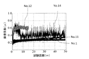
- the peel load of the film was measured using a scratch tester (REVETEST) manufactured by CSM.
- the measurement conditions are: measurement load: 0.9 to 120 N, load speed: 99.25 N / min, scratch speed: 10 mm / min, scratch distance: 12 mm, AE sensitivity: 5, indenter: Rockwell, diamond, tip radius: 200 ⁇ m
- the peeling critical load value of the film was a load value at which the frictional force obtained by measurement was changed, or a load when the hard film was completely peeled off from the mold.
- the measurement results are shown in Table 2 and FIG. From Table 2 and FIG. 1, the high adhesion of 90 N or more is obtained for any sample in the critical peeling load value. This is because the film is very thick as 5 ⁇ m or more, and among them, the film thickness of the A layer is 9 ⁇ m, which is thicker than other samples. No peeling occurred in No. 3 even at a measurement load of 120N.
- Heat resistance test In the heat test, in order to evaluate the oxidation resistance of the film, each sample was heated at 400 ° C. for 1 h in a constant temperature controlled atmospheric furnace, and then the film cross section was observed to check whether the film thickness was reduced or an oxide layer was formed. From this, the heat resistance of the coating was evaluated. For example, in the case of a DLC film made of C (carbon) or the like, if the film is oxidized, C of the film becomes CO 2 gas, and thus the film thickness is reduced. In the case of a nitride film, the nitride is replaced by an oxide as the oxidation proceeds, resulting in the formation of a low density oxide film. The measurement results are shown in Table 2 and FIG. None of the samples had any reduction in coating thickness or formation of an oxide layer after heating in an atmospheric furnace, and it was confirmed that there was no problem in heat resistance.
Priority Applications (6)
| Application Number | Priority Date | Filing Date | Title |
|---|---|---|---|
| ES16783294T ES2878165T3 (es) | 2015-04-23 | 2016-04-22 | Molde metálico revestido y método para producirlo |
| EP16783294.8A EP3287544B1 (en) | 2015-04-23 | 2016-04-22 | Coated metal mold and method for manufacturing same |
| KR1020177030103A KR102174803B1 (ko) | 2015-04-23 | 2016-04-22 | 피복 금형 및 그 제조 방법 |
| JP2017514223A JP6477867B2 (ja) | 2015-04-23 | 2016-04-22 | 被覆金型およびその製造方法 |
| US15/567,970 US11779989B2 (en) | 2015-04-23 | 2016-04-22 | Coated metal mold and method for manufacturing same |
| CN201680023253.8A CN107532279B (zh) | 2015-04-23 | 2016-04-22 | 包覆模具及其制造方法 |
Applications Claiming Priority (2)
| Application Number | Priority Date | Filing Date | Title |
|---|---|---|---|
| JP2015088365 | 2015-04-23 | ||
| JP2015-088365 | 2015-04-23 |
Publications (1)
| Publication Number | Publication Date |
|---|---|
| WO2016171273A1 true WO2016171273A1 (ja) | 2016-10-27 |
Family
ID=57143135
Family Applications (1)
| Application Number | Title | Priority Date | Filing Date |
|---|---|---|---|
| PCT/JP2016/062828 WO2016171273A1 (ja) | 2015-04-23 | 2016-04-22 | 被覆金型およびその製造方法 |
Country Status (7)
| Country | Link |
|---|---|
| US (1) | US11779989B2 (ko) |
| EP (1) | EP3287544B1 (ko) |
| JP (1) | JP6477867B2 (ko) |
| KR (1) | KR102174803B1 (ko) |
| CN (1) | CN107532279B (ko) |
| ES (1) | ES2878165T3 (ko) |
| WO (1) | WO2016171273A1 (ko) |
Cited By (13)
| Publication number | Priority date | Publication date | Assignee | Title |
|---|---|---|---|---|
| WO2018097286A1 (ja) * | 2016-11-28 | 2018-05-31 | 日立金属株式会社 | 金型およびその製造方法 |
| WO2018123831A1 (ja) * | 2016-12-28 | 2018-07-05 | 新日鐵住金株式会社 | 熱間プレス用めっき鋼板、熱間プレス用めっき鋼板の製造方法、熱間プレス成形品の製造方法、及び車両の製造方法 |
| WO2018124279A1 (ja) * | 2016-12-28 | 2018-07-05 | Dowaサーモテック株式会社 | 珪窒化バナジウム膜、珪窒化バナジウム膜被覆部材およびその製造方法 |
| JP2018158354A (ja) * | 2017-03-22 | 2018-10-11 | 新日鐵住金株式会社 | チタン板のプレス用金型及びチタン板のプレス成形方法 |
| JP2018158355A (ja) * | 2017-03-22 | 2018-10-11 | 新日鐵住金株式会社 | チタン板のプレス用金型及びチタン板のプレス成形方法 |
| JP2018164936A (ja) * | 2017-03-28 | 2018-10-25 | 日新製鋼株式会社 | 打抜き加工用金型及びそれを用いた打抜き加工方法 |
| WO2019198728A1 (ja) * | 2018-04-13 | 2019-10-17 | 日本製鉄株式会社 | 熱間プレス成形品の製造方法、プレス成形品、ダイ金型、及び金型セット |
| WO2020009170A1 (ja) * | 2018-07-04 | 2020-01-09 | 日本製鉄株式会社 | 熱間プレス成形品の製造方法、プレス成形品、ダイ金型、及び金型セット |
| WO2020009171A1 (ja) * | 2018-07-04 | 2020-01-09 | 日本製鉄株式会社 | 熱間プレス成形品の製造方法、プレス成形品、ダイ金型、及び金型セット |
| JP2020069506A (ja) * | 2018-10-31 | 2020-05-07 | 東洋製罐グループホールディングス株式会社 | 金属塑性加工用治具 |
| JP2020142322A (ja) * | 2019-03-06 | 2020-09-10 | 株式会社不二製作所 | Dlc被覆部材の表面処理方法 |
| WO2020189717A1 (ja) * | 2019-03-20 | 2020-09-24 | 日立金属株式会社 | 被覆金型、被覆金型の製造方法、および硬質皮膜形成用ターゲット |
| JP2021533254A (ja) * | 2018-06-18 | 2021-12-02 | イドロメカニーク エ フロットマン | クロム、炭素およびケイ素を含むアンダーコートの上を非水素化非晶質炭素コーティングで被覆した部品 |
Families Citing this family (3)
| Publication number | Priority date | Publication date | Assignee | Title |
|---|---|---|---|---|
| JP6874803B2 (ja) * | 2018-11-19 | 2021-05-19 | Jfeスチール株式会社 | 耐かじり性評価方法 |
| US20220032357A1 (en) * | 2018-12-03 | 2022-02-03 | Hitachi Metals, Ltd. | Coated die for use in hot stamping |
| KR20220151700A (ko) | 2020-04-20 | 2022-11-15 | 닛폰세이테츠 가부시키가이샤 | 열간 프레스 성형품의 제조 방법 및 열간 프레스 성형품 |
Citations (6)
| Publication number | Priority date | Publication date | Assignee | Title |
|---|---|---|---|---|
| JP2007313636A (ja) * | 2006-04-27 | 2007-12-06 | Kyocera Corp | 切削工具およびそれを用いた被削材の切削方法 |
| JP2009166096A (ja) * | 2008-01-17 | 2009-07-30 | Tocalo Co Ltd | プレス金型とその寿命管理方法、およびプレス金型のコーティング皮膜とその補修方法 |
| JP2010284710A (ja) * | 2009-06-15 | 2010-12-24 | Hitachi Metals Ltd | 塑性加工用被覆金型およびその製造方法 |
| JP2011183545A (ja) * | 2010-02-10 | 2011-09-22 | Hitachi Tool Engineering Ltd | 摺動特性に優れた被覆工具及びその製造方法 |
| JP2012115869A (ja) * | 2010-11-30 | 2012-06-21 | Kobe Steel Ltd | 塑性加工用金型およびその製造方法、ならびにアルミニウム材の鍛造方法 |
| JP2012232344A (ja) * | 2011-04-18 | 2012-11-29 | Nippon Koshuha Steel Co Ltd | プレス成形用金型及びプレス成形金型用保護膜の製造方法 |
Family Cites Families (14)
| Publication number | Priority date | Publication date | Assignee | Title |
|---|---|---|---|---|
| FR2825377B1 (fr) * | 2001-05-31 | 2003-09-19 | Essilor Int | Inserts de moulage |
| JP3621943B2 (ja) | 2003-07-25 | 2005-02-23 | 三菱重工業株式会社 | 高耐摩耗性高硬度皮膜 |
| JP4984206B2 (ja) | 2005-07-28 | 2012-07-25 | Dowaサーモテック株式会社 | ダイヤモンドライクカーボン皮膜被覆部材およびその製造方法 |
| JP2008074947A (ja) * | 2006-09-21 | 2008-04-03 | Nissan Motor Co Ltd | 低摩擦摺動機構及びこれを用いた摺動システム |
| JP5102516B2 (ja) | 2007-03-06 | 2012-12-19 | 株式会社神戸製鋼所 | 成形金型 |
| JP2013151707A (ja) * | 2010-04-01 | 2013-08-08 | Hitachi Ltd | 摺動部材 |
| JP5035479B2 (ja) * | 2011-01-27 | 2012-09-26 | 三菱マテリアル株式会社 | 耐欠損性、耐摩耗性にすぐれた表面被覆切削工具 |
| WO2013047548A1 (ja) | 2011-09-28 | 2013-04-04 | 日立ツール株式会社 | 摺動特性に優れた被覆部材 |
| CN103311281B (zh) * | 2012-03-14 | 2016-03-30 | 中国科学院微电子研究所 | 半导体器件及其制造方法 |
| JP5752640B2 (ja) * | 2012-05-30 | 2015-07-22 | 株式会社神戸製鋼所 | 成膜方法 |
| EP2957655B1 (en) * | 2013-03-22 | 2019-01-16 | Nittan Valve Co., Ltd. | Dlc coating film |
| JP2014196680A (ja) | 2013-03-29 | 2014-10-16 | 株式会社日立製作所 | 冷媒圧縮機 |
| US20150004362A1 (en) * | 2013-07-01 | 2015-01-01 | General Electric Company | Multilayered coatings with diamond-like carbon |
| JP5918326B2 (ja) | 2014-09-16 | 2016-05-18 | 株式会社リケン | 被覆摺動部材 |
-
2016
- 2016-04-22 KR KR1020177030103A patent/KR102174803B1/ko active IP Right Grant
- 2016-04-22 US US15/567,970 patent/US11779989B2/en active Active
- 2016-04-22 EP EP16783294.8A patent/EP3287544B1/en active Active
- 2016-04-22 WO PCT/JP2016/062828 patent/WO2016171273A1/ja active Application Filing
- 2016-04-22 JP JP2017514223A patent/JP6477867B2/ja active Active
- 2016-04-22 CN CN201680023253.8A patent/CN107532279B/zh active Active
- 2016-04-22 ES ES16783294T patent/ES2878165T3/es active Active
Patent Citations (6)
| Publication number | Priority date | Publication date | Assignee | Title |
|---|---|---|---|---|
| JP2007313636A (ja) * | 2006-04-27 | 2007-12-06 | Kyocera Corp | 切削工具およびそれを用いた被削材の切削方法 |
| JP2009166096A (ja) * | 2008-01-17 | 2009-07-30 | Tocalo Co Ltd | プレス金型とその寿命管理方法、およびプレス金型のコーティング皮膜とその補修方法 |
| JP2010284710A (ja) * | 2009-06-15 | 2010-12-24 | Hitachi Metals Ltd | 塑性加工用被覆金型およびその製造方法 |
| JP2011183545A (ja) * | 2010-02-10 | 2011-09-22 | Hitachi Tool Engineering Ltd | 摺動特性に優れた被覆工具及びその製造方法 |
| JP2012115869A (ja) * | 2010-11-30 | 2012-06-21 | Kobe Steel Ltd | 塑性加工用金型およびその製造方法、ならびにアルミニウム材の鍛造方法 |
| JP2012232344A (ja) * | 2011-04-18 | 2012-11-29 | Nippon Koshuha Steel Co Ltd | プレス成形用金型及びプレス成形金型用保護膜の製造方法 |
Cited By (36)
| Publication number | Priority date | Publication date | Assignee | Title |
|---|---|---|---|---|
| CN110023052B (zh) * | 2016-11-28 | 2022-05-31 | 日立金属株式会社 | 金属材料加工用模具及其制造方法 |
| KR102252719B1 (ko) * | 2016-11-28 | 2021-05-17 | 히다찌긴조꾸가부시끼가이사 | 금형 및 그 제조 방법 |
| WO2018097286A1 (ja) * | 2016-11-28 | 2018-05-31 | 日立金属株式会社 | 金型およびその製造方法 |
| KR20190077459A (ko) * | 2016-11-28 | 2019-07-03 | 히다찌긴조꾸가부시끼가이사 | 금형 및 그 제조 방법 |
| CN110023052A (zh) * | 2016-11-28 | 2019-07-16 | 日立金属株式会社 | 模具及其制造方法 |
| JPWO2018097286A1 (ja) * | 2016-11-28 | 2019-10-17 | 日立金属株式会社 | 金型およびその製造方法 |
| JP7029646B2 (ja) | 2016-11-28 | 2022-03-04 | 日立金属株式会社 | 金属材料加工用金型およびその製造方法、ならびに金型 |
| US11820048B2 (en) | 2016-11-28 | 2023-11-21 | Proterial, Ltd. | Mold and production method therefor |
| WO2018123831A1 (ja) * | 2016-12-28 | 2018-07-05 | 新日鐵住金株式会社 | 熱間プレス用めっき鋼板、熱間プレス用めっき鋼板の製造方法、熱間プレス成形品の製造方法、及び車両の製造方法 |
| WO2018124279A1 (ja) * | 2016-12-28 | 2018-07-05 | Dowaサーモテック株式会社 | 珪窒化バナジウム膜、珪窒化バナジウム膜被覆部材およびその製造方法 |
| JP6369659B1 (ja) * | 2016-12-28 | 2018-08-08 | 新日鐵住金株式会社 | 熱間プレス用めっき鋼板、熱間プレス用めっき鋼板の製造方法、熱間プレス成形品の製造方法、及び車両の製造方法 |
| US11072857B2 (en) | 2016-12-28 | 2021-07-27 | Dowa Thermotech Co., Ltd. | Vanadium silicon nitride film, member coated with vanadium silicon nitride film and method for manufacturing the same |
| JP2018158355A (ja) * | 2017-03-22 | 2018-10-11 | 新日鐵住金株式会社 | チタン板のプレス用金型及びチタン板のプレス成形方法 |
| JP2018158354A (ja) * | 2017-03-22 | 2018-10-11 | 新日鐵住金株式会社 | チタン板のプレス用金型及びチタン板のプレス成形方法 |
| JP2018164936A (ja) * | 2017-03-28 | 2018-10-25 | 日新製鋼株式会社 | 打抜き加工用金型及びそれを用いた打抜き加工方法 |
| JP7081662B2 (ja) | 2018-04-13 | 2022-06-07 | 日本製鉄株式会社 | 熱間プレス成形品の製造方法、プレス成形品、ダイ金型、及び金型セット |
| KR102385301B1 (ko) * | 2018-04-13 | 2022-04-11 | 닛폰세이테츠 가부시키가이샤 | 열간 프레스 성형품의 제조 방법, 프레스 성형품, 다이 금형 및 금형 세트 |
| WO2019198728A1 (ja) * | 2018-04-13 | 2019-10-17 | 日本製鉄株式会社 | 熱間プレス成形品の製造方法、プレス成形品、ダイ金型、及び金型セット |
| JPWO2019198728A1 (ja) * | 2018-04-13 | 2021-04-22 | 日本製鉄株式会社 | 熱間プレス成形品の製造方法、プレス成形品、ダイ金型、及び金型セット |
| KR20200125702A (ko) * | 2018-04-13 | 2020-11-04 | 닛폰세이테츠 가부시키가이샤 | 열간 프레스 성형품의 제조 방법, 프레스 성형품, 다이 금형 및 금형 세트 |
| CN111936248A (zh) * | 2018-04-13 | 2020-11-13 | 日本制铁株式会社 | 热压成型品的制造方法、压制成型品、冲模模具及模具套件 |
| JP2021533254A (ja) * | 2018-06-18 | 2021-12-02 | イドロメカニーク エ フロットマン | クロム、炭素およびケイ素を含むアンダーコートの上を非水素化非晶質炭素コーティングで被覆した部品 |
| JP7104806B2 (ja) | 2018-06-18 | 2022-07-21 | イドロメカニーク エ フロットマン | クロム、炭素およびケイ素を含むアンダーコートの上を非水素化非晶質炭素コーティングで被覆した部品 |
| WO2020009171A1 (ja) * | 2018-07-04 | 2020-01-09 | 日本製鉄株式会社 | 熱間プレス成形品の製造方法、プレス成形品、ダイ金型、及び金型セット |
| CN112236243A (zh) * | 2018-07-04 | 2021-01-15 | 日本制铁株式会社 | 热压成型品的制造方法、压制成型品、冲模模具及模具套件 |
| WO2020009170A1 (ja) * | 2018-07-04 | 2020-01-09 | 日本製鉄株式会社 | 熱間プレス成形品の製造方法、プレス成形品、ダイ金型、及び金型セット |
| US11633772B2 (en) | 2018-07-04 | 2023-04-25 | Nippon Steel Corporation | Hot press-formed item manufacturing method, press-formed item, die, and die set |
| US11491528B2 (en) | 2018-07-04 | 2022-11-08 | Nippon Steel Corporation | Hot press-formed item manufacturing method, press-formed item, die, and die set |
| CN112236244A (zh) * | 2018-07-04 | 2021-01-15 | 日本制铁株式会社 | 热压成型品的制造方法、压制成型品、冲模模具及模具套件 |
| JP6648875B1 (ja) * | 2018-07-04 | 2020-02-14 | 日本製鉄株式会社 | 熱間プレス成形品の製造方法、プレス成形品、ダイ金型、及び金型セット |
| JP6648874B1 (ja) * | 2018-07-04 | 2020-02-14 | 日本製鉄株式会社 | 熱間プレス成形品の製造方法、プレス成形品、ダイ金型、及び金型セット |
| JP2020069506A (ja) * | 2018-10-31 | 2020-05-07 | 東洋製罐グループホールディングス株式会社 | 金属塑性加工用治具 |
| JP2020142322A (ja) * | 2019-03-06 | 2020-09-10 | 株式会社不二製作所 | Dlc被覆部材の表面処理方法 |
| KR102308453B1 (ko) | 2019-03-06 | 2021-10-06 | 후지 세이사쿠쇼 가부시키가이샤 | Dlc코팅부재의 표면처리방법 |
| KR20200107737A (ko) * | 2019-03-06 | 2020-09-16 | 후지 세이사쿠쇼 가부시키가이샤 | Dlc코팅부재의 표면처리방법 |
| WO2020189717A1 (ja) * | 2019-03-20 | 2020-09-24 | 日立金属株式会社 | 被覆金型、被覆金型の製造方法、および硬質皮膜形成用ターゲット |
Also Published As
| Publication number | Publication date |
|---|---|
| JP6477867B2 (ja) | 2019-03-06 |
| EP3287544A4 (en) | 2019-01-02 |
| US11779989B2 (en) | 2023-10-10 |
| JPWO2016171273A1 (ja) | 2017-11-09 |
| KR102174803B1 (ko) | 2020-11-05 |
| ES2878165T3 (es) | 2021-11-18 |
| CN107532279A (zh) | 2018-01-02 |
| CN107532279B (zh) | 2020-10-30 |
| EP3287544A1 (en) | 2018-02-28 |
| US20180141102A1 (en) | 2018-05-24 |
| EP3287544B1 (en) | 2021-06-16 |
| KR20170129876A (ko) | 2017-11-27 |
Similar Documents
| Publication | Publication Date | Title |
|---|---|---|
| JP6477867B2 (ja) | 被覆金型およびその製造方法 | |
| JP5351875B2 (ja) | 塑性加工用金型およびその製造方法、ならびにアルミニウム材の鍛造方法 | |
| JP6015663B2 (ja) | 摺動特性に優れた被覆部材 | |
| JP5920681B2 (ja) | 摺動特性に優れた塑性加工用被覆金型及びその製造方法 | |
| JP6211987B2 (ja) | Znめっき鋼板の熱間成形用金型 | |
| WO2011125657A1 (ja) | 耐食性に優れた被覆物品の製造方法および被覆物品 | |
| JP6274317B2 (ja) | ダイカスト用被覆金型の製造方法 | |
| JP5616082B2 (ja) | セラミックス被覆材の製造方法 | |
| JP6569376B2 (ja) | 超硬工具及びその製造方法 | |
| JP6308298B2 (ja) | 被覆工具の製造方法 | |
| JP2010284710A (ja) | 塑性加工用被覆金型およびその製造方法 | |
| JP5988144B2 (ja) | 耐食性に優れた被覆物品およびその製造方法 | |
| JP2013076124A (ja) | 耐食性に優れた被覆物品の製造方法および被覆物品 | |
| JP2024061966A (ja) | 金属塑性加工用金型及びその製造方法 | |
| JP5892414B2 (ja) | 耐食性に優れた被覆物品の製造方法および被覆物品 | |
| JP2006206960A (ja) | 硬質皮膜被覆摺動部材 |
Legal Events
| Date | Code | Title | Description |
|---|---|---|---|
| 121 | Ep: the epo has been informed by wipo that ep was designated in this application |
Ref document number: 16783294 Country of ref document: EP Kind code of ref document: A1 |
|
| ENP | Entry into the national phase |
Ref document number: 2017514223 Country of ref document: JP Kind code of ref document: A |
|
| ENP | Entry into the national phase |
Ref document number: 20177030103 Country of ref document: KR Kind code of ref document: A |
|
| WWE | Wipo information: entry into national phase |
Ref document number: 15567970 Country of ref document: US |
|
| NENP | Non-entry into the national phase |
Ref country code: DE |
|
| WWE | Wipo information: entry into national phase |
Ref document number: 2016783294 Country of ref document: EP |