WO2016171027A1 - シートの吊り込み構造およびシートにおけるトリムカバーの吊り込み方法 - Google Patents
シートの吊り込み構造およびシートにおけるトリムカバーの吊り込み方法 Download PDFInfo
- Publication number
- WO2016171027A1 WO2016171027A1 PCT/JP2016/061726 JP2016061726W WO2016171027A1 WO 2016171027 A1 WO2016171027 A1 WO 2016171027A1 JP 2016061726 W JP2016061726 W JP 2016061726W WO 2016171027 A1 WO2016171027 A1 WO 2016171027A1
- Authority
- WO
- WIPO (PCT)
- Prior art keywords
- seat
- trim cover
- suspension
- linear
- hanging
- Prior art date
Links
Images


Classifications
-
- B—PERFORMING OPERATIONS; TRANSPORTING
- B60—VEHICLES IN GENERAL
- B60N—SEATS SPECIALLY ADAPTED FOR VEHICLES; VEHICLE PASSENGER ACCOMMODATION NOT OTHERWISE PROVIDED FOR
- B60N2/00—Seats specially adapted for vehicles; Arrangement or mounting of seats in vehicles
- B60N2/58—Seat coverings
- B60N2/5816—Seat coverings attachments thereof
- B60N2/5825—Seat coverings attachments thereof by hooks, staples, clips, snap fasteners or the like
-
- B—PERFORMING OPERATIONS; TRANSPORTING
- B60—VEHICLES IN GENERAL
- B60N—SEATS SPECIALLY ADAPTED FOR VEHICLES; VEHICLE PASSENGER ACCOMMODATION NOT OTHERWISE PROVIDED FOR
- B60N2/00—Seats specially adapted for vehicles; Arrangement or mounting of seats in vehicles
- B60N2/90—Details or parts not otherwise provided for
-
- B—PERFORMING OPERATIONS; TRANSPORTING
- B68—SADDLERY; UPHOLSTERY
- B68G—METHODS, EQUIPMENT, OR MACHINES FOR USE IN UPHOLSTERING; UPHOLSTERY NOT OTHERWISE PROVIDED FOR
- B68G7/00—Making upholstery
- B68G7/05—Covering or enveloping cores of pads
Definitions
- the present invention relates to a seat suspension structure and a trim cover suspension method for a seat.
- a structure for attaching a trim cover (surface cover) to a foam cushion material molded into a seat shape a groove-like suspended portion is formed in the cushion material, and a part of the trim cover is attached to the suspended portion.
- a structure is used in which the trim cover is hung by inserting and fastening to the cushion material.
- Patent Document 1 a hanging cloth (hanging bag) is sewn on the back surface of a trim cover (seat cover), and the hanging cloth and a wire embedded in a cushion material (seat back wire) Has been disclosed that is suspended by hogging with a C-ring (see Patent Document 1).
- An object of the present invention is to provide a seat suspending structure and a method for suspending a trim cover in a sheet, which can eliminate the labor and cost of sewing a hanging cloth on the back surface of the trim cover.
- the present invention provides a seat suspension structure in which a trim cover is suspended and supported with respect to a sheet member constituting the seat.
- a linear suspension member for suspension disposed on the surface side of the trim cover;
- the trim cover is inserted into the suspending groove together with the linear suspending member, and is fastened without using a suspension cloth. For this reason, it is possible to suspend the trim cover without sewing the hanging cloth.
- an insert member for locking the fastening member is provided inside the sheet member. By locking one of the fastening members to the insert member, the fastening member is more difficult to come off.
- a marking indicating a position where the linear suspension member is to be disposed is provided on the surface of the trim cover.
- the present invention also relates to a hanging method when a trim cover is hung on a seat member formed with a groove for hanging and attached to the sheet member, and the hanger is linearly hung on the surface side of the trim cover.
- Arrange the suspension members Wrapping the linear suspension member on the surface side of the trim cover, The linear suspension member wrapped with the trim cover is inserted into the suspension groove formed in the sheet member, together with a part of the sheet member, The linear suspension member is fastened to the sheet member by a fastening member.
- the labor and cost of sewing the hanging cloth on the back surface of the trim cover can be eliminated.
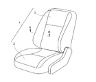
- FIG. 1 It is a perspective view showing one embodiment of a sheet concerning the present invention. It is a perspective view which shows a mode that a linear suspension member is arrange
- the seat 1 includes a seat 2 that can move back and forth on the floor panel of the vehicle, and a backrest 3 that can be reclined with respect to the seat 2.
- Each of the seat 2 and the backrest 3 is a seat member constituting the seat 1 and includes a cushion material 4 made of a foam.
- the trim cover 7 can be attached to and detached from the seat 2 and the backrest 3 by using the suspension structure 10.
- the cushion material 4 constituting the backrest 3 has a main cushion portion 41 for supporting the occupant's back from behind and a side cushion portion 42 for holding the occupant's back from the side (see FIG. 3). ).
- the trim cover 7 includes a main surface portion 71 placed on the main cushion portion 41 of the cushion material 4 and a part of the side cushion portion 42, a side surface portion 72 placed on the remaining portion of the side cushion portion 42, Is formed by.
- the main surface portion 71 and the side surface portion 72 of the trim cover 7 are joined together by a stitching portion 74 in a state where the surfaces of the trim cover 7 are in contact with each other, and the front surface faces the seated person and the back surface faces the cushion material 4 side. 4, the stitched portion 74 and the portion of the trim cover 7 beyond the stitched portion 74 are not exposed to the surface side (see FIGS. 3 and 4).
- the suspension structure 10 includes a suspension groove 11, a linear suspension member 14, an insert wire 16, and a hog ring 18 (see FIG. 3 and the like).
- the hanging groove 11 is composed of a recess 12 formed at a predetermined depth in the longitudinal direction of the backrest 2 along the boundary portion between the main cushion portion 41 and the side cushion portion 42, and forms the appearance of the seat 1. .
- the recess 12 is pressed and closed between the main cushion portion 41 and the side cushion portion 42 by the elasticity of the cushion material 4, but for the sake of convenience, in FIG. 3 and FIG.
- the recessed part 12 of the state which showed is shown.
- the backrest 3 is further provided with a hanging groove 11 extending along the lateral method (width direction of the backrest 3) in addition to the above-described hanging groove 11, and the seat 2 is also provided with the hanging groove 11.
- the description will be continued by taking the hanging groove 11 formed of the concave portion 12 formed in the vertical direction as described above as an example.
- the insert wire 16 is embedded in the cushion material 4 of the backrest 2 in a portion deeper by a predetermined amount than the bottom of the recess 12 (see FIG. 3. In FIG. 3, the groove depth direction of the recess 12 is shown. (Denoted by the symbol D).
- the predetermined amount here is an amount suitable for fastening in consideration of the size of the hog ring 18 and the like when fastening the linear suspension member 14 and the insert wire 16 with the hog ring 18 (see FIG. 4). ).
- the insert wire 16 has a direction in which the recess 12 is formed (in this embodiment, a boundary portion between the main cushion portion 41 and the side cushion portion 42).
- the wire may extend straight in the longitudinal direction), or may be a wire in which the portion to which the hog ring 18 is fastened is bent in a crank shape toward the recess 12.
- the linear suspension member 14 is disposed on the surface of the trim cover 7 (the surface on the side opposite to the cushion material 4 and serving as a skin on which the seated person touches the seat 1), and is suspended together with a part of the trim cover 7.
- the trim cover 7 is suspended by being inserted into the groove 11.
- the linear suspension member 14 may be made of metal such as iron or aluminum, may be made of resin such as polypropylene or polyethylene, or may be made of rubber. Both ends of the linear suspension member 14 formed of a linear wire are rounded so as to be easy to handle during work and difficult to move in the longitudinal direction inside the suspension groove 11 (see FIG. 2). .
- a marking 20 indicating a position where the linear suspension member 14 is to be disposed is attached to a predetermined position on the surface of the trim cover 7 (see FIG. 2).
- the marking 20 is composed of, for example, small holes (dots) formed on the surface of the trim cover 7, ruled lines, and the like.
- the hog ring 18 fastens the linear suspension member 14 inserted into the suspension groove 11 to the sheet member.
- the hog ring 18 can be easily fastened to a predetermined position in the hanging groove 11 by using a dedicated tool (hog ring fastening device).
- the hog ring 18 is substantially C-shaped, and one end penetrates the trim cover 7 from the back surface side and is hooked on the linear suspension member 14, and the other end is thrust into the cushion material 4 and hooked on the insert wire 16 and pressed. It deform
- the linear suspension member 14 is disposed at a predetermined position on the surface side of the trim cover 7 while using the marking 20 as a mark (see FIGS. 2 and 3). Thereafter, the linear suspension member 14 is inserted into the suspension groove 11 while being wrapped in the trim cover 7 (see FIG. 3).
- the hog ring fastening device (not shown) is used to fasten the linear suspension member 14 and the insert wire 16 with the hog ring 18 (see FIGS. 3 and 4). Similarly, the linear suspension member 14 and the insert wire 16 are fastened by the hog ring 18 at other predetermined locations. As described above, the linear suspension member 14 is fastened to the backrest 3 together with a part of the trim cover 7, and the suspension operation is completed.
- a part of the trim cover 7 together with the linear hanging member 14 can be inserted into the hanging groove 11 and fastened to the cushion material 4 without a hanging cloth (hanging bag). It can. That is, since the trim cover 7 can be hung without sewing the hanging cloth on the back surface of the trim cover 7, the labor and cost of sewing the hanging cloth as in the conventional hanging structure can be eliminated.
- the trim cover 7 inserted into the hanging groove 11 is pulled to deform the hog ring 18 that is locked to the linear suspension member 14 and the insert wire 16. To release the fastening.
- the seat 1 according to the present invention can be used for aircraft seats, passenger ship seats and the like in addition to automobile seats.
- the provision of the insert member such as the insert wire 16 in the cushion material 4 can alleviate local deformation of the cushion material 4 and make the hog ring 18 difficult to move or come off.
- the insert member may not necessarily be provided as long as the hog ring 18 can be firmly fastened only by the cushion material 4.
- the hog ring 18 in the above-described embodiment is merely a preferred example of a fastening member that fastens the linear suspension member 14 and the insert wire 16, and other C-shaped rings or other various fastening tools are used. Can be used.
- the present invention is preferably applied to a seat suspension structure in which a trim cover is suspended and supported with respect to a sheet member constituting the seat.
Abstract
シートを構成するシート部材(3)に対してトリムカバー(7)を吊り込み支持するシートの吊り込み構造(10)であり、該吊り込み構造(10)は、トリムカバー(7)の表面側に配置された吊り込み用の線状吊り部材(14)と、シート部材(3)に形成された吊り込み用の溝部(11)に差し込まれた状態の線状吊り部材(14)をシート部材(3)に留め付ける留付部材(18)と、を有する。シート部材(3)内部に、留付部材(18)を係止させるインサート部材(16)が設けられていることが好ましい。
Description
本発明は、シートの吊り込み構造およびシートにおけるトリムカバーの吊り込み方法に関する。
座席形状にモールド加工した発泡体クッション材に対してトリムカバー(表面カバー)を取り付けるための構造として、クッション材に溝状の吊り込み部を形成し、該吊り込み部にトリムカバーの一部を差し込み、クッション材に締結してトリムカバーを吊り込む構造が利用されている。
このような吊り込み構造として、特許文献1では、トリムカバー(シートカバー)の裏面に吊り布(吊り袋)を縫い付けておき、該吊り布と、クッション材に埋め込んだワイヤー(シートバックワイヤー)とをCリングでホグリング止めすることによって吊り込む構造が開示されている(特許文献1参照)。
しかしながら、この吊り込み構造においては、トリムカバーの裏面に吊り布を縫製する必要があることから、その分の手間とコストが生じている。
本発明は、トリムカバーの裏面に吊り布を縫製する手間とコストをなくすことが可能なシートの吊り込み構造およびシートにおけるトリムカバーの吊り込み方法を提供することを目的とする。
かかる課題を解決するべく、本発明は、シートを構成するシート部材に対してトリムカバーを吊り込み支持するシートの吊り込み構造において、
前記トリムカバーの表面側に配置された吊り込み用の線状吊り部材と、
前記シート部材に形成された吊り込み用の溝部に差し込まれた状態の前記線状吊り部材を前記シート部材に留め付ける留付部材と、
を有することを特徴とする。
前記トリムカバーの表面側に配置された吊り込み用の線状吊り部材と、
前記シート部材に形成された吊り込み用の溝部に差し込まれた状態の前記線状吊り部材を前記シート部材に留め付ける留付部材と、
を有することを特徴とする。
この吊り込み構造においては、線状吊り部材ごとトリムカバーが吊り込み用の溝に差し込まれ、吊り布を介することなく留め付けられている。このため、トリムカバーの裏面に吊り布を縫製せずとも吊り込むことが可能となっている。
この吊り込み構造において、前記シート部材内部に、前記留付部材を係止させるインサート部材が設けられていることが好ましい。インサート部材に留付部材の一方を係止させることで、留付部材がより抜けづらい状態となる。
また、前記トリムカバーの表面に、前記線状吊り部材が配置されるべき位置を示すマーキングがされていることが好ましい。
また、本発明は、吊り込み用の溝部が形成されたシート部材にトリムカバーを吊り込んで該シート部材に取り付ける際の吊り込み方法であって
前記トリムカバーの表面側に吊り込み用の線状吊り部材を配置し、
該線状吊り部材を前記トリムカバーの表面側で包み込み、
前記シート部材に形成された吊り込み用の溝部に、前記トリムカバーで包み込まれた前記線状吊り部材を前記シート部材の一部ごと差し込み、
前記線状吊り部材を、留付部材によって前記シート部材に留め付ける
ことを特徴とする。
前記トリムカバーの表面側に吊り込み用の線状吊り部材を配置し、
該線状吊り部材を前記トリムカバーの表面側で包み込み、
前記シート部材に形成された吊り込み用の溝部に、前記トリムカバーで包み込まれた前記線状吊り部材を前記シート部材の一部ごと差し込み、
前記線状吊り部材を、留付部材によって前記シート部材に留め付ける
ことを特徴とする。
本発明によれば、トリムカバーの裏面に吊り布を縫製する手間とコストをなくすことができる。
以下、図面を参照しつつ本発明に係るシートの吊り込み構造および吊り込み方法の好適な実施形態について詳細に説明する(図1~図4参照)。
シート1は、車両のフロアパネル上で前後に移動可能な座2と、座2に対してリクライニング可能な背もたれ3とを備える。座2および背もたれ3は、それぞれ、シート1を構成するシート部材であり、発泡体からなるクッション材4を備えている。また、座2および背もたれ3には、吊り込み構造10を利用してトリムカバー7の着脱が可能となっている。
ここで、背もたれ3を例に挙げて説明する。背もたれ3を構成するクッション材4は、乗員の背中を後方から支持するためのメインクッション部41と、乗員の背中を横から保持するためのサイドクッション部42とを有している(図3参照)。
トリムカバー7は、クッション材4のメインクッション部41上およびサイドクッション部42の一部に載置される主面部71と、サイドクッション部42の残りの部分に載置されるサイド面部72と、によって形成されている。トリムカバー7の主面部71とサイド面部72は、互いの表面どうしを接触させた状態で縫合部74によって接合されており、表面が着座者の側、裏面がクッション材4側を向いてクッション材4に被せられたとき、縫合部74およびトリムカバー7の該縫合部74から先の部分が表面側に露出しない(図3、図4参照)。
次に、吊り込み構造10について説明する。吊り込み構造10は、吊り込み溝11、線状吊り部材14、インサートワイヤー16、ホッグリング18で構成される(図3等参照)。
吊り込み溝11は、メインクッション部41とサイドクッション部42との境界部分に沿って背もたれ2の縦方向に所定の深さに形成された凹部12からなるもので、シート1の外観を形成する。通常時、凹部12は、クッション材4の弾力によってメインクッション部41とサイドクッション部42との間で圧迫され塞がった状態となるが、便宜上、図3、図4においては理解しやすいように拡がった状態の凹部12を示している。
なお、背もたれ3には、上述した吊り込み溝11の他、横方法(背もたれ3の幅方向)に沿って延びる吊り込み溝11がさらに設けられ、また、座2にも吊り込み溝11が設けられているが(図1、図2参照)、本実施形態では上述したように縦方向に形成された凹部12からなる吊り込み溝11を例に説明を続ける。
インサートワイヤー16は、背もたれ2のクッション材4の内部であって、凹部12の底から所定量深い部分に埋設されている(図3参照。なお、図3では、凹部12の溝深さ方向を符号Dで表している)。ここでいう所定量は、ホッグリング18で線状吊り部材14と当該インサートワイヤー16とを留め付ける際、当該ホッグリング18のサイズ等を考慮して留め付けに適した量である(図4参照)。
なお、図ではインサートワイヤー16の具体的形状を示していないが、インサートワイヤー16は、凹部12が形成された方向(本実施形態であれば、メインクッション部41とサイドクッション部42との境界部分に沿った縦方向)に真っ直ぐ延びるワイヤーであってもがよいし、ホッグリング18が留め付けられる部分が凹部12寄りにクランク状に曲折したワイヤーであってもよい。
線状吊り部材14は、トリムカバー7の表面(クッション材4とは反対側の面で、シート1において着座者が触れる表皮となる面)側に配置され、トリムカバー7の一部とともに吊り込み溝11に差し込まれ、トリムカバー7を吊り込む。線状吊り部材14は鉄、アルミニウムといった金属製でもよいし、ポリプロピレン、ポリエチレンといった樹脂製、あるいはゴム製などであってもよい。線状ワイヤーで形成された線状吊り部材14は、作業時に扱いやすく、かつ、吊り込み溝11の内部で長手方向に動きづらくなるように、その両端部が丸められている(図2参照)。
また、トリムカバー7の表面の所定位置には、線状吊り部材14が配置されるべき位置を示すマーキング20が付されている(図2参照)。このマーキング20を目印にすることにより、線状吊り部材14を所定の位置に配置してトリムカバー7ごと吊り込み溝11に差し込むことができる。マーキング20は、例えばトリムカバー7の表面に形成した小孔(ドット)、罫書き線などで構成される。
ホッグリング18は、吊り込み溝11に差し込まれた状態の線状吊り部材14をシート部材に留め付ける。特に図示しないが、専用の工具(ホッグリング締結装置)を使うことによってホッグリング18を吊り込み溝11内の所定位置に簡単に留め付けることができる。ホッグリング18は略C字形であり、一端がトリムカバー7を裏面側から突き抜けて線状吊り部材14に引っ掛けられ、他端がクッション材4に突き刺されてインサートワイヤー16に引っ掛けられ、押圧されて変形し、両者を締結する(図3、図4参照)。
続いて、上述した吊り込み構造10によりトリムカバー7を吊り込む際の手順を簡単に説明する。
まず、トリムカバー7の表面側の所定位置に、マーキング20を目印にしつつ線状吊り部材14を配置する(図2、図3参照)。その後、線状吊り部材14を、トリムカバー7で包み込んだ状態のまま吊り込み溝11に差し込む(図3参照)。
次に、ホッグリング締結装置(図示省略)を用い、ホッグリング18で線状吊り部材14とインサートワイヤー16を締結する(図3、図4参照)。同様にして、他の所定箇所でもホッグリング18で線状吊り部材14とインサートワイヤー16を締結する。以上により、線状吊り部材14をトリムカバー7の一部ごと背もたれ3に留め付け、吊り込み作業を終了する。
ここまで説明した吊り込み構造10によれば、線状吊り部材14ごとトリムカバー7の一部を吊り込み溝11に差し込み、吊り布(吊り袋)を介することなくクッション材4に留め付けることができる。すなわち、トリムカバー7の裏面に吊り布を縫製せずともトリムカバー7を吊り込むことができることから、従来の吊り込み構造におけるような吊り布を縫製する手間とコストをなくすことができる。
また、クッション材4からトリムカバー7を取り外す際には、吊り込み溝11に差し込まれているトリムカバー7を引っ張り、線状吊り部材14およびインサートワイヤー16と係止しているホッグリング18を変形させて締結を解除させる。
なお、上述の実施形態は本発明の好適な実施の一例ではあるがこれに限定されるものではなく本発明の要旨を逸脱しない範囲において種々変形実施可能である。例えば、本発明に係るシート1は、自動車用シートのほか、航空機用シート、旅客船用シートなどに利用することができる。
また、上述した実施形態のごとく、クッション材4にインサートワイヤー16等のインサート部材が設けられていることが、クッション材4の局所的変形を緩和し、ホッグリング18が動きづらくあるいは抜けづらくしうる点で好ましいが、クッション材4のみでもホッグリング18を堅固に留め付けることが可能であれば、必ずしもインサート部材が設けられていなくてもよい。
また、上述した実施形態におけるホッグリング18は線状吊り部材14とインサートワイヤー16とを締結する留付部材の好適な一例にすぎず、この他のC形リング、あるいはその他種々の留付具を利用することができる。
本発明は、シートを構成するシート部材に対してトリムカバーを吊り込み支持するシートの吊り込み構造に適用して好適である。
1…シート
2…座(シート部材)
3…背もたれ(シート部材)
4…クッション材
7…トリムカバー
10…吊り込み構造
11…吊り込み溝(吊り込み用の溝部)
14…線状吊り部材
16…インサートワイヤー(インサート部材)
18…ホッグリング(留付部材)
20…マーキング
2…座(シート部材)
3…背もたれ(シート部材)
4…クッション材
7…トリムカバー
10…吊り込み構造
11…吊り込み溝(吊り込み用の溝部)
14…線状吊り部材
16…インサートワイヤー(インサート部材)
18…ホッグリング(留付部材)
20…マーキング
Claims (4)
- シートを構成するシート部材に対してトリムカバーを吊り込み支持するシートの吊り込み構造において、
前記トリムカバーの表面側に配置された吊り込み用の線状吊り部材と、
前記シート部材に形成された吊り込み用の溝部に差し込まれた状態の前記線状吊り部材を前記シート部材に留め付ける留付部材と、
を有することを特徴とするシートの吊り込み構造。 - 前記シート部材内部に、前記留付部材を係止させるインサート部材が設けられていることを特徴とする請求項1に記載のシートの吊り込み構造。
- 前記トリムカバーの表面に、前記線状吊り部材が配置されるべき位置を示すマーキングがされていることを特徴とする請求項1または2に記載のシートの吊り込み構造。
- 吊り込み用の溝部が形成されたシート部材にトリムカバーを吊り込んで該シート部材に取り付ける際の吊り込み方法であって
前記トリムカバーの表面側に吊り込み用の線状吊り部材を配置し、
該線状吊り部材を前記トリムカバーの表面側で包み込み、
前記シート部材に形成された吊り込み用の溝部に、前記トリムカバーで包み込まれた前記線状吊り部材を前記シート部材の一部ごと差し込み、
前記線状吊り部材を、留付部材によって前記シート部材に留め付ける
ことを特徴とする、シートにおけるトリムカバーの吊り込み方法。
Priority Applications (1)
| Application Number | Priority Date | Filing Date | Title |
|---|---|---|---|
| US15/567,226 US20180105084A1 (en) | 2015-04-24 | 2016-04-11 | Hooking Structure of Seat and Method of Hooking Trim Cover in Seat |
Applications Claiming Priority (2)
| Application Number | Priority Date | Filing Date | Title |
|---|---|---|---|
| JP2015-089322 | 2015-04-24 | ||
| JP2015089322A JP6703809B2 (ja) | 2015-04-24 | 2015-04-24 | シートの吊り込み構造およびシートにおけるトリムカバーの吊り込み方法 |
Publications (1)
| Publication Number | Publication Date |
|---|---|
| WO2016171027A1 true WO2016171027A1 (ja) | 2016-10-27 |
Family
ID=57144430
Family Applications (1)
| Application Number | Title | Priority Date | Filing Date |
|---|---|---|---|
| PCT/JP2016/061726 WO2016171027A1 (ja) | 2015-04-24 | 2016-04-11 | シートの吊り込み構造およびシートにおけるトリムカバーの吊り込み方法 |
Country Status (3)
| Country | Link |
|---|---|
| US (1) | US20180105084A1 (ja) |
| JP (1) | JP6703809B2 (ja) |
| WO (1) | WO2016171027A1 (ja) |
Families Citing this family (6)
| Publication number | Priority date | Publication date | Assignee | Title |
|---|---|---|---|---|
| US9776353B2 (en) * | 2013-10-02 | 2017-10-03 | Velcro BVBA | Longitudinal bead molding |
| JP6578154B2 (ja) * | 2015-04-24 | 2019-09-18 | 株式会社タチエス | シートの吊り込み構造 |
| JP6539167B2 (ja) * | 2015-07-09 | 2019-07-03 | 株式会社タチエス | シートの吊り込み構造 |
| US10808336B2 (en) | 2018-05-31 | 2020-10-20 | GM Global Technology Operations LLC | Vehicle seat trim covers with knitted attachment structures formed with heat-activated yarns |
| US10532675B2 (en) * | 2018-05-31 | 2020-01-14 | GM Global Technology Operations LLC | Vehicle seat trim cover with integrally knitted attachment features |
| US10843600B2 (en) | 2018-07-12 | 2020-11-24 | GM Global Technology Operations LLC | Vehicle seat trim covers including integrally-knit backing materials and methods of manufacturing vehicle seat trim covers |
Citations (2)
| Publication number | Priority date | Publication date | Assignee | Title |
|---|---|---|---|---|
| JP2002022578A (ja) * | 2000-07-05 | 2002-01-23 | Denso Corp | 自動車用の乗員判別システム |
| JP2009160261A (ja) * | 2008-01-08 | 2009-07-23 | Toyota Boshoku Corp | シート表皮 |
Family Cites Families (5)
| Publication number | Priority date | Publication date | Assignee | Title |
|---|---|---|---|---|
| US4557522A (en) * | 1983-12-06 | 1985-12-10 | Tachikawa Spring Co., Ltd. | Vehicle seat |
| JPH042638Y2 (ja) * | 1987-11-30 | 1992-01-29 | ||
| JP2003212019A (ja) * | 2002-01-22 | 2003-07-30 | Tachi S Co Ltd | 車両用シートのシートクッション構造 |
| JP3735681B2 (ja) * | 2002-07-08 | 2006-01-18 | 日本発条株式会社 | 自動車用シート |
| JP5465505B2 (ja) * | 2009-10-02 | 2014-04-09 | 東洋ゴム工業株式会社 | 車両用シートパッド |
-
2015
- 2015-04-24 JP JP2015089322A patent/JP6703809B2/ja active Active
-
2016
- 2016-04-11 WO PCT/JP2016/061726 patent/WO2016171027A1/ja active Application Filing
- 2016-04-11 US US15/567,226 patent/US20180105084A1/en not_active Abandoned
Patent Citations (2)
| Publication number | Priority date | Publication date | Assignee | Title |
|---|---|---|---|---|
| JP2002022578A (ja) * | 2000-07-05 | 2002-01-23 | Denso Corp | 自動車用の乗員判別システム |
| JP2009160261A (ja) * | 2008-01-08 | 2009-07-23 | Toyota Boshoku Corp | シート表皮 |
Also Published As
| Publication number | Publication date |
|---|---|
| JP6703809B2 (ja) | 2020-06-03 |
| US20180105084A1 (en) | 2018-04-19 |
| JP2016202673A (ja) | 2016-12-08 |
Similar Documents
| Publication | Publication Date | Title |
|---|---|---|
| WO2016171027A1 (ja) | シートの吊り込み構造およびシートにおけるトリムカバーの吊り込み方法 | |
| JP6307419B2 (ja) | シート | |
| JP6292003B2 (ja) | 乗物用シート | |
| CN107848449B (zh) | 座椅导引结构 | |
| WO2016171045A1 (ja) | シート | |
| WO2016084653A1 (ja) | シート | |
| JP6578154B2 (ja) | シートの吊り込み構造 | |
| JP6322296B2 (ja) | シート | |
| US20170303700A1 (en) | Seat | |
| JP6292100B2 (ja) | 乗物用シート | |
| JP2018007717A (ja) | シートカバーの引き込み構造 | |
| WO2016084766A1 (ja) | シート | |
| US20170305319A1 (en) | Vehicle seat | |
| WO2016208298A1 (ja) | シートの吊り込み構造およびシートにおけるトリムカバーの吊り込み方法 | |
| CN107521389A (zh) | 头枕罩 | |
| WO2017138351A1 (ja) | クッション材のインサート部材固定構造 | |
| WO2017188000A1 (ja) | シートの吊り込み構造、シートカバーおよびシート | |
| JP6450796B2 (ja) | 乗物用シート | |
| WO2017006883A1 (ja) | シートの吊り込み構造 | |
| JP2015155271A (ja) | 車両用ベンチシート | |
| WO2016084652A1 (ja) | シート | |
| JP6570677B2 (ja) | カバー部材 | |
| JP3138362U (ja) | 連結用介在具およびこれを用いたシートへのシートカバーの取付け構造 | |
| JP2007145212A (ja) | 自動車用収納具 | |
| JP2022083101A (ja) | 吊り込み部材およびそれを用いたシートの吊り込み構造 |
Legal Events
| Date | Code | Title | Description |
|---|---|---|---|
| 121 | Ep: the epo has been informed by wipo that ep was designated in this application |
Ref document number: 16783048 Country of ref document: EP Kind code of ref document: A1 |
|
| WWE | Wipo information: entry into national phase |
Ref document number: 15567226 Country of ref document: US |
|
| NENP | Non-entry into the national phase |
Ref country code: DE |
|
| 122 | Ep: pct application non-entry in european phase |
Ref document number: 16783048 Country of ref document: EP Kind code of ref document: A1 |