WO2016170749A1 - 弁装置、及び、弁装置の製造装置 - Google Patents
弁装置、及び、弁装置の製造装置 Download PDFInfo
- Publication number
- WO2016170749A1 WO2016170749A1 PCT/JP2016/001954 JP2016001954W WO2016170749A1 WO 2016170749 A1 WO2016170749 A1 WO 2016170749A1 JP 2016001954 W JP2016001954 W JP 2016001954W WO 2016170749 A1 WO2016170749 A1 WO 2016170749A1
- Authority
- WO
- WIPO (PCT)
- Prior art keywords
- valve
- hole
- intermediate member
- jig
- valve device
- Prior art date
- Legal status (The legal status is an assumption and is not a legal conclusion. Google has not performed a legal analysis and makes no representation as to the accuracy of the status listed.)
- Ceased
Links
Images


Classifications
-
- F—MECHANICAL ENGINEERING; LIGHTING; HEATING; WEAPONS; BLASTING
- F02—COMBUSTION ENGINES; HOT-GAS OR COMBUSTION-PRODUCT ENGINE PLANTS
- F02M—SUPPLYING COMBUSTION ENGINES IN GENERAL WITH COMBUSTIBLE MIXTURES OR CONSTITUENTS THEREOF
- F02M61/00—Fuel-injectors not provided for in groups F02M39/00 - F02M57/00 or F02M67/00
- F02M61/16—Details not provided for in, or of interest apart from, the apparatus of groups F02M61/02 - F02M61/14
- F02M61/18—Injection nozzles, e.g. having valve seats; Details of valve member seated ends, not otherwise provided for
- F02M61/188—Spherical or partly spherical shaped valve member ends
-
- F—MECHANICAL ENGINEERING; LIGHTING; HEATING; WEAPONS; BLASTING
- F02—COMBUSTION ENGINES; HOT-GAS OR COMBUSTION-PRODUCT ENGINE PLANTS
- F02M—SUPPLYING COMBUSTION ENGINES IN GENERAL WITH COMBUSTIBLE MIXTURES OR CONSTITUENTS THEREOF
- F02M51/00—Fuel-injection apparatus characterised by being operated electrically
- F02M51/06—Injectors peculiar thereto with means directly operating the valve needle
- F02M51/061—Injectors peculiar thereto with means directly operating the valve needle using electromagnetic operating means
- F02M51/0625—Injectors peculiar thereto with means directly operating the valve needle using electromagnetic operating means characterised by arrangement of mobile armatures
- F02M51/0664—Injectors peculiar thereto with means directly operating the valve needle using electromagnetic operating means characterised by arrangement of mobile armatures having a cylindrically or partly cylindrically shaped armature, e.g. entering the winding; having a plate-shaped or undulated armature entering the winding
- F02M51/0671—Injectors peculiar thereto with means directly operating the valve needle using electromagnetic operating means characterised by arrangement of mobile armatures having a cylindrically or partly cylindrically shaped armature, e.g. entering the winding; having a plate-shaped or undulated armature entering the winding the armature having an elongated valve body attached thereto
-
- F—MECHANICAL ENGINEERING; LIGHTING; HEATING; WEAPONS; BLASTING
- F02—COMBUSTION ENGINES; HOT-GAS OR COMBUSTION-PRODUCT ENGINE PLANTS
- F02M—SUPPLYING COMBUSTION ENGINES IN GENERAL WITH COMBUSTIBLE MIXTURES OR CONSTITUENTS THEREOF
- F02M55/00—Fuel-injection apparatus characterised by their fuel conduits or their venting means; Arrangements of conduits between fuel tank and pump F02M37/00
- F02M55/008—Arrangement of fuel passages inside of injectors
-
- F—MECHANICAL ENGINEERING; LIGHTING; HEATING; WEAPONS; BLASTING
- F02—COMBUSTION ENGINES; HOT-GAS OR COMBUSTION-PRODUCT ENGINE PLANTS
- F02M—SUPPLYING COMBUSTION ENGINES IN GENERAL WITH COMBUSTIBLE MIXTURES OR CONSTITUENTS THEREOF
- F02M61/00—Fuel-injectors not provided for in groups F02M39/00 - F02M57/00 or F02M67/00
- F02M61/16—Details not provided for in, or of interest apart from, the apparatus of groups F02M61/02 - F02M61/14
- F02M61/161—Means for adjusting injection-valve lift
-
- F—MECHANICAL ENGINEERING; LIGHTING; HEATING; WEAPONS; BLASTING
- F02—COMBUSTION ENGINES; HOT-GAS OR COMBUSTION-PRODUCT ENGINE PLANTS
- F02M—SUPPLYING COMBUSTION ENGINES IN GENERAL WITH COMBUSTIBLE MIXTURES OR CONSTITUENTS THEREOF
- F02M61/00—Fuel-injectors not provided for in groups F02M39/00 - F02M57/00 or F02M67/00
- F02M61/16—Details not provided for in, or of interest apart from, the apparatus of groups F02M61/02 - F02M61/14
- F02M61/165—Filtering elements specially adapted in fuel inlets to injector
-
- F—MECHANICAL ENGINEERING; LIGHTING; HEATING; WEAPONS; BLASTING
- F02—COMBUSTION ENGINES; HOT-GAS OR COMBUSTION-PRODUCT ENGINE PLANTS
- F02M—SUPPLYING COMBUSTION ENGINES IN GENERAL WITH COMBUSTIBLE MIXTURES OR CONSTITUENTS THEREOF
- F02M61/00—Fuel-injectors not provided for in groups F02M39/00 - F02M57/00 or F02M67/00
- F02M61/16—Details not provided for in, or of interest apart from, the apparatus of groups F02M61/02 - F02M61/14
- F02M61/168—Assembling; Disassembling; Manufacturing; Adjusting
-
- F—MECHANICAL ENGINEERING; LIGHTING; HEATING; WEAPONS; BLASTING
- F02—COMBUSTION ENGINES; HOT-GAS OR COMBUSTION-PRODUCT ENGINE PLANTS
- F02M—SUPPLYING COMBUSTION ENGINES IN GENERAL WITH COMBUSTIBLE MIXTURES OR CONSTITUENTS THEREOF
- F02M61/00—Fuel-injectors not provided for in groups F02M39/00 - F02M57/00 or F02M67/00
- F02M61/16—Details not provided for in, or of interest apart from, the apparatus of groups F02M61/02 - F02M61/14
- F02M61/20—Closing valves mechanically, e.g. arrangements of springs or weights or permanent magnets; Damping of valve lift
-
- F—MECHANICAL ENGINEERING; LIGHTING; HEATING; WEAPONS; BLASTING
- F02—COMBUSTION ENGINES; HOT-GAS OR COMBUSTION-PRODUCT ENGINE PLANTS
- F02M—SUPPLYING COMBUSTION ENGINES IN GENERAL WITH COMBUSTIBLE MIXTURES OR CONSTITUENTS THEREOF
- F02M21/00—Apparatus for supplying engines with non-liquid fuels, e.g. gaseous fuels stored in liquid form
- F02M21/02—Apparatus for supplying engines with non-liquid fuels, e.g. gaseous fuels stored in liquid form for gaseous fuels
- F02M21/0218—Details on the gaseous fuel supply system, e.g. tanks, valves, pipes, pumps, rails, injectors or mixers
- F02M21/0248—Injectors
- F02M21/0278—Port fuel injectors for single or multipoint injection into the air intake system
-
- F—MECHANICAL ENGINEERING; LIGHTING; HEATING; WEAPONS; BLASTING
- F02—COMBUSTION ENGINES; HOT-GAS OR COMBUSTION-PRODUCT ENGINE PLANTS
- F02M—SUPPLYING COMBUSTION ENGINES IN GENERAL WITH COMBUSTIBLE MIXTURES OR CONSTITUENTS THEREOF
- F02M2200/00—Details of fuel-injection apparatus, not otherwise provided for
- F02M2200/50—Arrangements of springs for valves used in fuel injectors or fuel injection pumps
- F02M2200/505—Adjusting spring tension by sliding spring seats
Definitions
- the present disclosure relates to a valve device and a device for manufacturing the valve device.
- a fuel injection valve that opens and closes an injection hole formed in a housing by reciprocating movement of a needle and injects fuel in the housing.
- the fuel injection valve includes a drive unit that can drive the needle in the valve opening direction, and a spring that biases the needle in the valve closing direction.
- the driving force output from the driving unit and the biasing force of the spring act on the needle. Since the urging force of the spring is determined by the distance between the adjusting pipe press-fitted and fixed to the housing and the needle, it is necessary to accurately adjust the position where the adjusting pipe is fixed when manufacturing the fuel injection valve.
- the flow rate of the fluid flowing through the fuel injection valve is maintained at a predetermined constant flow rate while changing the amount by which the adjusting pipe is pushed into the fixed core and the control value of the control current supplied to the drive unit.
- a fuel injection valve adjustment method for adjusting the pushing amount of the adjusting pipe so that the control current becomes the target control value is described.
- An object of the present disclosure is to provide a valve device that can set the biasing force with high accuracy while shortening the time required for adjusting the biasing force of the biasing member.
- a valve device in one aspect of the present disclosure, includes a valve housing having a hole through which fluid can flow and a valve seat formed around the hole, a cylindrical member fixed inside the valve housing or integrally formed with the valve housing A valve member that is reciprocally movable in the valve housing and opens or closes the hole when it is separated from the valve seat or abuts on the valve seat, and the first end abuts the valve member and attaches the valve member in the valve closing direction or valve opening direction.
- An urging member capable of being urged, an intermediate member provided so as to abut against the second end of the urging member, and a hole press-fitted and fixed inside the cylindrical member so as to abut on the opposite side of the urging member of the intermediate member; Has a communication path that communicates the opposite side and the hole side, and an adjustment member that can adjust the urging force of the urging member via the intermediate member according to the relative position with respect to the cylindrical member when fixed to the cylindrical member; Is provided.
- the bias device of the present disclosure When the valve device of the present disclosure is provided so as to be relatively movable with respect to the tubular member in a product state or in an actual use state, when the valve device of the present disclosure is manufactured, the bias device is biased through the intermediate member. The biasing force of the member is detected. Based on the relationship between the detected biasing force of the biasing member and the position of the intermediate member, the adjustment member is press-fitted and fixed at a position where the biasing force of the biasing member becomes a predetermined biasing force. Thereby, the position which fixes an adjustment member based on the change of the biasing force of a biasing member can be determined.
- the biasing force of the biasing member can be adjusted by dry adjustment that does not require fluid, rather than wet adjustment that determines the position at which the adjustment member is fixed based on a change in fluid flow rate while actually flowing fluid.
- the time for adjusting the biasing force of the biasing member can be shortened.
- the intermediate member is provided so as to be relatively movable with respect to the cylindrical member, and therefore, the urging force of the urging member that acts on the intermediate member can be detected with high accuracy.
- the adjustment member can be fixed so that the urging force of the urging member becomes a predetermined urging force, and the urging force of the urging member in the product state or the actual use state can be set with high accuracy.
- the intermediate member is provided so as not to move relative to the cylindrical member.
- the urging force of the urging member is detected via the intermediate member, and the adjustment member is fixed based on the detected urging force of the urging member. After the adjustment member is fixed, the intermediate member is not allowed to move relative to the tubular member.
- the valve device of the present disclosure can be prevented from changing the position of the intermediate member due to the resistance of the fluid flowing inside the valve device in a product state or an actual use state.
- the urging force of the urging member is set with high precision while shortening the time for adjusting the urging force of the urging member by making the intermediate member relatively movable with respect to the cylindrical member at the time of manufacture.
- the biasing force of the biasing member can be stabilized by disabling relative movement of the member with respect to the cylindrical member.
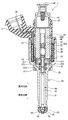
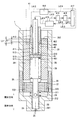
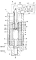
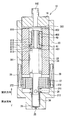
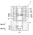
- FIG. 1 is a cross-sectional view of a fuel injection valve according to a first embodiment of the present disclosure
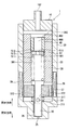
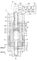
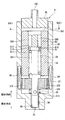
- FIG. 2 is a schematic diagram of a fuel injection valve according to the first embodiment of the present disclosure
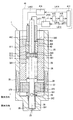
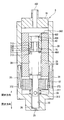
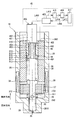
- FIG. 3 is a schematic diagram in the middle of manufacturing the fuel injection valve for explaining an adjustment method for adjusting the biasing force of the spring of the fuel injection valve according to the first embodiment of the present disclosure
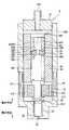
- FIG. 4 is a schematic diagram in the process of manufacturing the fuel injection valve for explaining the adjustment method for adjusting the biasing force of the spring of the fuel injection valve according to the first embodiment of the present disclosure, and the state is different from FIG. 3.
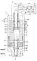
- FIG. 5 is a schematic diagram in the process of manufacturing the fuel injection valve for explaining an adjustment method for adjusting the biasing force of the spring of the fuel injection valve according to the first embodiment of the present disclosure.
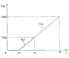
- FIG. 6 is a characteristic diagram showing the relationship between the position of the adjusting pipe of the fuel injection valve and the biasing force of the spring according to the first embodiment of the present disclosure
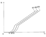
- FIG. 7 is a characteristic diagram showing the relationship between the time from the fuel injection start command and the fuel injection amount in the fuel injection valve according to the first embodiment of the present disclosure
- FIG. 8 is a schematic diagram illustrating an adjustment method for adjusting the biasing force of the spring of the fuel injection valve according to the second embodiment of the present disclosure.
- FIG. 6 is a characteristic diagram showing the relationship between the position of the adjusting pipe of the fuel injection valve and the biasing force of the spring according to the first embodiment of the present disclosure
- FIG. 7 is a characteristic diagram showing the relationship between the time from the fuel injection start command and the fuel injection amount in the fuel injection valve according to the first embodiment of the present
- FIG. 9 is a schematic diagram of a fuel injection valve according to the third embodiment of the present disclosure
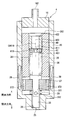
- FIG. 10 is a schematic diagram of a fuel injection valve according to the fourth embodiment of the present disclosure
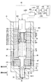
- FIG. 11 is a schematic diagram of a fuel injection valve manufacturing apparatus according to a fifth embodiment of the present disclosure
- FIG. 12 is a schematic diagram illustrating an adjustment method for a fuel injection valve manufacturing apparatus according to a sixth embodiment of the present disclosure
- FIG. 13 is a schematic diagram of a fuel injection valve according to a seventh embodiment of the present disclosure
- FIG. 14 is a schematic diagram of a fuel injection valve according to an eighth embodiment of the present disclosure
- FIG. 15 is a schematic diagram of a fuel injection valve according to the ninth embodiment of the present disclosure
- FIG. 16 is a schematic diagram of a fuel injection valve according to a tenth embodiment of the present disclosure
- FIG. 17 is a schematic diagram in the middle of manufacturing of the fuel injection valve for explaining an adjustment method for adjusting the biasing force of the spring of the fuel injection valve according to the tenth embodiment of the present disclosure
- FIG. 18 is a schematic diagram in the middle of manufacturing the fuel injection valve for explaining the adjustment method for adjusting the biasing force of the spring of the fuel injection valve according to the tenth embodiment of the present disclosure, and the state is different from FIG.
- FIG. 19 is a schematic diagram in the course of manufacturing the fuel injection valve for explaining an adjustment method for adjusting the biasing force of the spring of the fuel injection valve according to the tenth embodiment of the present disclosure.
- FIG. 20 is a schematic diagram of a fuel injection valve according to the eleventh embodiment of the present disclosure
- 21 is a cross-sectional view taken along line XXI-XXI in FIG.
- FIG. 22 is a schematic diagram of a fuel injection valve according to a twelfth embodiment of the present disclosure
- FIG. 23 is a schematic diagram of a valve device according to a fourteenth embodiment of the present disclosure
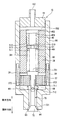
- FIG. 24 is a schematic diagram of a fuel injection valve according to a fifteenth embodiment of the present disclosure.
- First embodiment 1 and 2 show a fuel injection valve 1 as a valve device according to a first embodiment of the present disclosure. 1 and 2 illustrate a valve opening direction in which the needle 30 is separated from the valve seat 26 and a valve closing direction in which the needle 30 is in contact with the valve seat 26.
- the fuel injection valve 1 is used, for example, in a fuel injection device of a direct injection gasoline engine (not shown), and injects and supplies gasoline as fuel to the engine at a high pressure.
- the fuel injection valve 1 includes a housing 20 as a valve housing, a needle 30 as a valve member, a movable core 37, a fixed core 38 as a cylindrical member, a coil 39, a spring 28 as a biasing member, a spring 29, and an adjustment member. Adjusting pipe 40, intermediate member 51, and the like.
- the housing 20 includes a first cylinder member 21, a second cylinder member 22, a third cylinder member 23, and an injection nozzle 24.
- the first cylinder member 21, the second cylinder member 22, and the third cylinder member 23 are all formed in a substantially cylindrical shape, and are coaxial in the order of the first cylinder member 21, the second cylinder member 22, and the third cylinder member 23. Arranged and connected to each other.
- the injection nozzle 24 is provided at the end of the first cylinder member 21 opposite to the second cylinder member 22.
- the injection nozzle 24 is formed in a bottomed cylindrical shape.
- the injection nozzle 24 has an injection hole 25 as a hole communicating the inside and the outside of the housing 20 at the bottom.
- a valve seat 26 is formed around the inside of the injection hole 25.
- the needle 30 is formed of a shaft portion 31, a seal portion 32, a flange portion 33, and the like.
- the shaft portion 31, the seal portion 32, and the flange portion 33 are integrally formed.
- the shaft portion 31 is formed in a cylindrical rod shape.
- the shaft portion 31 has a passage 311 at an end portion on the fixed core 38 side.
- the passage 311 communicates with the inside of the fixed core 38.
- the passage 311 communicates with the nozzle hole 25 side of the movable core 37 through a through hole 312 that penetrates the shaft portion 31 in the radial direction.
- the seal portion 32 is provided at an end portion of the shaft portion 31 on the nozzle hole 25 side.
- the seal portion 32 can contact the valve seat 26.
- the flange portion 33 is provided on the radially outer side of the end portion of the shaft portion 31 opposite to the seal portion 32.
- the end surface of the flange portion 33 on the nozzle hole 25 side is in contact with the movable core 37.
- the needle 30 reciprocates inside the housing 20.
- the needle 30 opens and closes the nozzle hole 25 when the seal portion 32 is separated from the valve seat 26 or the seal portion 32 abuts on the valve seat 26, and communicates or blocks the inside and the outside of the housing 20.
- the movable core 37 is formed in a substantially cylindrical shape, and is provided on the nozzle hole 25 side of the flange portion 33.
- the movable core 37 is subjected to a magnetic stabilization process.
- a through hole 371 is formed in the approximate center of the movable core 37.
- the shaft portion 31 of the needle 30 is inserted into the through hole 371.
- a passage 372 that connects the fixed core 38 side of the movable core 37 and the injection hole 25 side is formed in the radially outward direction of the through hole 371.
- the fixed core 38 is formed in a substantially cylindrical shape, and is provided on the side opposite to the injection hole 25 of the movable core 37.
- the fixed core 38 is subjected to a magnetic stabilization process.
- the fixed core 38 is welded to the third cylinder member 23 of the housing 20 and is fixed to the inside of the housing 20.
- the coil 39 is formed in a substantially cylindrical shape and is provided so as to mainly surround the radially outer sides of the second cylinder member 22 and the third cylinder member 23.
- the coil 39 generates a magnetic field when electric power is supplied.
- a magnetic field is generated around the coil 39, a magnetic circuit is formed in the fixed core 38, the movable core 37, the first cylinder member 21, the third cylinder member 23, and the holder 19.
- a magnetic attractive force is generated between the fixed core 38 and the movable core 37, and the movable core 37 is attracted to the fixed core 38.
- the needle 30 in contact with the end surface of the movable core 37 opposite to the valve seat 26 moves together with the movable core 37 in the stationary core 38 side, that is, in the valve opening direction.
- the spring 28 is a compression spring, and is provided so that the first end is in contact with the end surface of the flange portion 33 opposite to the nozzle hole 25. The second end of the spring 28 is in contact with the intermediate member 51.
- the spring 28 has a force extending in the axial direction. The spring 28 urges the needle 30 together with the movable core 37 in the direction of the valve seat 26, that is, in the valve closing direction.
- the spring 29 is a compression spring, and the first end is provided so as to contact the end surface of the movable core 37 on the injection hole 25 side. The second end of the spring 29 is in contact with the inner wall 211 of the first cylinder member 21.
- the spring 29 has a force extending in the axial direction. The spring 29 urges the movable core 37 together with the needle 30 in the direction opposite to the valve seat 26, that is, in the valve opening direction.
- the urging force of the spring 28 is set larger than the urging force of the spring 29.
- the adjusting pipe 40 is a cylindrical member provided inside the fixed core 38.
- the adjusting pipe 40 is formed so that the outer diameter is equal to the inner diameter of the fixed core 38.
- the adjusting pipe 40 is press-fitted and fixed inside the fixed core 38.
- the adjusting pipe 40 has one communication path 400 that communicates the opposite side of the adjusting pipe 40 from the injection hole 25 and the injection hole 25 side at substantially the center.
- the intermediate member 51 is provided between the adjusting pipe 40 and the spring 28.
- the end surface 511 of the intermediate member 51 on the nozzle hole 25 side is in contact with the second end of the spring 28.
- An end surface 512 of the intermediate member 51 opposite to the injection hole 25 is in contact with an end surface 401 of the adjusting pipe 40 on the injection hole 25 side.
- a gap is formed between the radially outer outer wall 513 of the intermediate member 51 and the radially inner wall 381 of the fixed core 38. Thereby, the intermediate member 51 can be moved relative to the fixed core 38.
- the intermediate member 51 has a communication hole 510 that communicates the opposite side to the injection hole 25 and the injection hole 25 side.
- a substantially cylindrical fuel introduction pipe 16 is press-fitted and welded to the end of the third cylinder member 23 opposite to the second cylinder member 22.
- a filter 161 is provided inside the fuel introduction pipe 16. The filter 161 collects foreign matter contained in the fuel that has flowed from the introduction port 162 of the fuel introduction pipe 16.
- the radially outer sides of the fuel introduction pipe 16 and the third cylinder member 23 are molded with resin.
- a connector 17 is formed in the mold part.
- the connector 17 is insert-molded with a terminal 18 for supplying electric power to the coil 39.
- a cylindrical holder 19 is provided outside the coil 39 in the radial direction so as to cover the coil 39.
- a part of the fuel flowing from the introduction port 162 of the fuel introduction pipe 16 is inside the fixed core 38, the communication path 400, the communication hole 510, the path 311, the communication hole 312, and the shaft of the first cylindrical member 21 and the needle 30. It flows through the gap between the portions 31 and is guided into the injection nozzle 24. Further, a part of the fuel flowing in from the introduction port 162 is inside the fixed core 38, the communication path 400, the communication hole 510, the flange 33 and the fixed core 38, the path 372, and the first cylinder member 21. It flows through the gap between the shaft portion 31 of the needle 30 and is guided to the inside of the injection nozzle 24. That is, a fuel passage for introducing fuel into the injection nozzle 24 extends from the introduction port 162 of the fuel introduction pipe 16 to the gap between the first cylindrical member 21 and the shaft portion 31 of the needle 30.
- FIG. 6 shows the relationship between the position of the adjusting pipe 40 and the biasing force of the spring 28.
- the horizontal axis in FIG. 6 shows the position of the adjusting pipe 40 with respect to the fixed core 38. Specifically, the distance L from the end surface 382 opposite to the injection hole 25 of the fixed core 38 to the end surface 402 of the adjusting pipe 40 in the direction of the central axis CA1 is shown. That is, when the end surface 382 and the end surface 402 are on the same plane, the distance L is zero. Further, when the adjusting pipe 40 moves in the valve closing direction from the position where the distance L is 0, the distance L becomes positive.
- the configuration of the urging force adjusting device 41 as a valve device manufacturing device used in the adjustment process of the urging force of the spring 28 will be described.
- the urging force adjusting device 41 includes a first jig 411, a second jig 412, a first drive unit 413 that drives the first jig 411, a second drive unit 414 that drives the second jig 412, and a detection unit 415. , A calculation unit 416, and a control unit 417 for controlling two driving units.
- the first jig 411 is a substantially rod-shaped member.
- the first jig 411 is connected to the first drive unit 413 (a chain line L411 in FIG. 3).
- the first jig 411 can reciprocate in the direction of the central axis CA1 of the fuel injection valve 1.
- the first jig 411 can abut on the end surface 512 of the intermediate member 51 via the communication path 400.
- the second jig 412 is a substantially cylindrical member provided on the outer side in the radial direction of the first jig 411.
- tool 412 is connected with the 2nd drive part 414 (dashed line L412 of FIG. 3).
- the second jig 412 can reciprocate in the direction of the central axis CA1 of the fuel injection valve 1.
- the second jig 412 can abut on the end surface 402 of the adjusting pipe 40 opposite to the nozzle hole 25.
- the detection unit 415 is electrically connected to the first drive unit 413 (two-dot chain line L415 in FIG. 3).
- the detection unit 415 detects the biasing force of the spring 28 based on the acting force from the spring 28 acting on the first jig 411 when the first driving unit 413 drives the first jig 411 to the nozzle hole 25 side. .
- the detection unit 415 detects the moving distance of the first jig 411.
- the detection unit 415 outputs a signal corresponding to the detected magnitude of the biasing force of the spring 28 and the movement distance of the first jig 411 to the calculation unit 416.
- the calculation unit 416 is electrically connected to the detection unit 415 (two-dot chain line L416 in FIG. 3).
- the calculation unit 416 determines whether the biasing force of the spring 28 is a predetermined biasing force based on a signal corresponding to the magnitude of the biasing force of the spring 28 output from the detection unit 415 and the moving distance of the first jig 411.
- the pipe set position as the adjustment member set position of the adjusting pipe 40 that becomes the urging force Fsp3 is calculated.
- the calculation unit 416 outputs a signal corresponding to the pipe set position to the control unit 417.
- the control unit 417 is electrically connected to the first drive unit 413, the second drive unit 414, and the calculation unit 416 (two-dot chain lines L413, L414, and L417 in FIG. 3).
- the control unit 417 outputs a first control signal to the first drive unit 413 and controls the reciprocation of the first jig 411.
- the control unit 417 outputs a signal corresponding to the pipe set position to the second drive unit 414 to control the reciprocation of the second jig 412.
- the spring 28 is assembled to the fuel injection valve 1 to which the fuel introduction pipe 16 is not assembled.
- the intermediate member 51 and the adjusting pipe 40 are inserted into the fixed core 38. Since the outer diameter of the intermediate member 51 is smaller than the inner diameter of the fixed core 38, the intermediate member 51 can freely reciprocate in the direction of the central axis CA1. The intermediate member 51 inserted into the fixed core 38 abuts on the second end of the spring 28.
- the adjusting pipe 40 Since the adjusting pipe 40 has an outer diameter equal to the inner diameter of the fixed core 38, the adjusting pipe 40 is press-fitted into the fixed core 38 by pressing the second jig 412. The first jig 411 is kept in contact with the intermediate member 51 until the adjusting pipe 40 to be pressed contacts the intermediate member 51 (the distance L in FIG. 5 is from 0 to L1). ing. Since the length of the spring 28 at this time is a natural length, the biasing force of the spring 28 detected by the detection unit 415 is zero.
- the adjusting pipe 40 comes into contact with the intermediate member 51 (see FIG. 4). Thereafter, the intermediate member 51 and the adjusting pipe 40 are moved in the valve closing direction by the first jig 411 and the second jig 412 while the adjusting pipe 40 and the intermediate member 51 are kept in contact with each other. At this time, the detection unit 415 detects the biasing force of the spring 28 according to the distance L.
- the calculation unit 416 calculates the distance L and the spring 28 based on the biasing force of the spring 28 detected by the detection unit 415. Is derived from the urging force Fsp (solid line portion FL1 between the distance L1 and the distance L2 in FIG. 6). The distance that the adjusting pipe 40 can move before the relationship between the distance L and the urging force Fsp is derived is a distance calculated in advance so that the urging force of the spring 28 is smaller than the target urging force Fsp3. Let L2.
- the calculation unit 416 calculates a distance L3 from the end surface 382 to the end surface 402 when the biasing force of the spring 28 becomes the target biasing force Fsp3 based on the relationship between the derived distance L and the biasing force Fsp (FIG. 6 is a dotted line portion FL2 between a distance L2 and a distance L3). That is, in the fuel injection valve 1, the pipe set position of the adjusting pipe 40 is a position where the distance from the end surface 382 to the end surface 402 is the distance L3.
- the control unit 417 causes the second drive unit 414 to perform the second treatment so that the distance from the end surface 382 to the end surface 402 becomes the distance L3.
- the tool 412 is pushed in the valve closing direction (see FIG. 5).
- the adjustment process of the biasing force of the spring 28 is finished.
- the horizontal axis indicates time Ti from the fuel injection start command
- the vertical axis indicates the fuel injection amount Qi of the fuel injection valve 1.
- the origin of the horizontal axis is when power supply to the coil 39 is started.
- the needle 30 is separated from the valve seat 26 and opened after a certain amount of time has elapsed since the supply of power to the coil 39 was started.
- the valve opening behavior of the fuel injection valve 1 is determined by the suction force between the movable core 37 and the fixed core 38 that drive the needle 30 in the valve opening direction, and the biasing force of the springs 28 and 29 that bias the needle 30. Determined by balance.
- the urging force of the spring 28 is determined by the pipe set position of the adjusting pipe 40 that is press-fitted into the fixed core 38.
- the time when the fuel injection valve 1 starts fuel injection changes.
- the adjusting pipe 40 is not sufficiently press-fitted and the pipe set position is shallow, that is, at a position relatively close to the fuel introduction pipe 16, the biasing force of the spring 28 becomes smaller than the target biasing force. Therefore, fuel injection is started at time T1 earlier than time T0, which is the target fuel injection start timing, and the fuel injection amount is as indicated by a two-dot chain line QT1.
- the adjusting pipe 40 is press-fitted deep into the fixed core 38 and the pipe set position is deep, that is, close to the needle 30, the biasing force of the spring 28 becomes larger than the target biasing force. For this reason, fuel injection is started at time T2 later than the target time T0, and the fuel injection amount is as indicated by a two-dot chain line QT2.
- an intermediate member 51 capable of detecting the biasing force of the spring 28 without being influenced by the press-fit state of the adjusting pipe 40 is provided between the adjusting pipe 40 and the spring 28. ing.
- the relationship between the position of the adjusting pipe 40 and the biasing force of the spring 28 is derived. Based on the derived relationship, the pipe set position of the adjusting pipe that uses the biasing force of the spring 28 as a target biasing force is calculated.
- the adjusting pipe 40 is fixed to the calculated pipe set position. Therefore, the fuel injection valve 1 can set the biasing force of the spring 28 with high accuracy. Therefore, the time from when the supply of electric power to the coil 39 is started to when the fuel injection is actually started can be set with high accuracy.
- the biasing force of the spring 28 can be set with high accuracy, the biasing force of the spring 28 can be set as the target biasing force by dry adjustment that does not actually inject the fluid. it can. Thereby, the fuel injection valve 1 can shorten the time which adjusts urging
- FIG. 8 shows an urging force adjusting device 42 as a valve device manufacturing apparatus according to the second embodiment.
- the urging force adjusting device 42 includes a first jig 411, a second jig 412, a first drive unit 413, a second drive unit 414, a detection unit 415, a storage unit 426, a control unit 417, and the like. .
- the storage unit 426 is electrically connected to the detection unit 415 and the control unit 417 (two-dot chain lines L426 and L417 in FIG. 8).
- the storage unit 426 stores the movement distance of the intermediate member 51 when the biasing force of the spring 28 becomes the target biasing force Fsp3.
- the storage unit 426 outputs a signal corresponding to the stored movement distance to the control unit 417.
- the intermediate member 51 and the adjusting pipe 40 are inserted into the fuel injection valve 1 to which the spring 28 is assembled. At this time, the adjusting pipe 40 moves the distance L ⁇ b> 1 so as to contact the intermediate member 51 that is in contact with the spring 28 by pressing the second jig 412.
- the detecting member 415 pushes the intermediate member 51 toward the nozzle hole 25 by the first jig 411 while detecting the urging force of the spring 28. At this time, the intermediate member 51 is pushed in until the biasing force of the spring 28 acting on the intermediate member 51 becomes the target biasing force Fsp3 (see FIG. 8).
- the storage unit 426 included in the biasing force adjusting device 42 has an intermediate member set position where the biasing force of the spring 28 acting on the intermediate member 51 becomes the target biasing force Fsp3 from the position where the adjusting pipe 40 and the intermediate member 51 abut.
- the distance of movement of the intermediate member 51 to the intermediate set position that is, the distance (L3-L1) is stored.
- the control unit 417 drives the second jig 412 and moves the adjusting pipe 40 by the distance (L3-L1). Push in.
- the adjusting pipe 40 is fixed at a pipe set position where the biasing force of the spring 28 becomes the target biasing force Fsp3.
- the urging force adjusting device 42 uses the first jig 411 that can detect the urging force of the spring 28, and the distance at which the urging force of the spring 28 first becomes the target urging force Fsp3. (L3-L1) is stored. Thereafter, the adjusting pipe 40 is moved by a distance (L3-L1). Thereby, the biasing force of the spring 28 can be set with high accuracy.
- FIG. 3 a valve device according to a third embodiment of the present disclosure will be described based on FIG.
- the third embodiment is different from the first embodiment in the shape of the intermediate member.
- symbol is attached
- FIG. 9 shows a fuel injection valve 3 as a valve device according to the third embodiment.
- the intermediate member 56 provided in the fuel injection valve 3 is provided between the adjusting pipe 40 and the spring 28.
- the intermediate member 56 has a communication hole 560 that communicates the opposite side to the injection hole 25 and the injection hole 25 side.
- the inner diameter of the communication hole 560 is smaller than the inner diameter of the communication hole 510 included in the intermediate member 51 of the first embodiment.
- the inner diameter of the communication hole 560 of the intermediate member 56 is relatively small. Accordingly, the communication hole 560 functions as an orifice with respect to the fuel flow inside the fuel injection valve 3, and the fuel flowing from the communication path 400 to the injection hole 25 side of the intermediate member 56 can be throttled. Thereby, the pressure pulsation inside the fuel injection valve 3 can be reduced.
- the fourth embodiment differs from the first embodiment in the shape of the intermediate member.
- symbol is attached
- FIG. 10 shows a fuel injection valve 4 as a valve device according to the fourth embodiment.
- the intermediate member 61 provided in the fuel injection valve 4 is provided between the adjusting pipe 40 and the spring 28.
- the intermediate member 61 has a communication hole 610 that communicates the opposite side to the injection hole 25 and the injection hole 25 side.
- the inner edge of the communication hole 610 opposite to the injection hole 25 has an inner edge slope 611 formed so as to be away from the central axis CA 610 of the communication hole 610 from the injection hole 25 side toward the opposite side of the injection hole 25.
- the fuel introduced into the housing 20 through the inlet 162 flows from the side having the inner edge slope 611 toward the injection hole 25. At this time, the fuel can smoothly flow into the communication hole 610 by the inner edge slope 611. Thereby, the resistance of the fuel which acts on the intermediate member 61 can be reduced, and the intermediate member 61 can be prevented from being displaced toward the nozzle hole 25 side. Therefore, it is possible to prevent the biasing force of the spring 28 from changing due to the flow of fuel.
- the fifth embodiment differs from the fourth embodiment in the shape of the first jig.
- symbol is attached
- FIG. 11 shows an urging force adjusting device 43 as a valve device manufacturing apparatus according to the fifth embodiment.
- the urging force adjusting device 43 includes a first jig 431, a second jig 412, a first drive unit 413 that drives the first jig 431, a second drive unit 414, a detection unit 415, a calculation unit 416, and a control. It consists of part 417 and the like.
- the first jig 431 is formed in a substantially rod shape.
- the first jig 431 is connected to the first drive unit 413 (a chain line L431 in FIG. 11).
- the first jig 431 has a tip slope 432 at the outer edge of the end that can contact the intermediate member 61.
- the tip slope 432 is formed so as to move away from the central axis CA43 of the first jig 431 from the side contacting the intermediate member 61 toward the side opposite to the side contacting the intermediate member 61.
- the tip slope 432 of the first jig 431 can contact the inner edge slope 611 of the intermediate member 61. Therefore, the centering of the first jig 431 with respect to the intermediate member 61 can be easily performed. Therefore, the biasing force of the spring 28 can be set with higher accuracy.
- FIG. 12 shows an urging force adjusting device 44 as a valve device manufacturing apparatus according to the sixth embodiment.
- the urging force adjusting device 44 includes a first jig 441, a second jig 412, a first drive unit 413 that drives the first jig 441, a second drive unit 414, a detection unit 415, a calculation unit 416, and a control. It consists of part 417 and the like.
- the first jig 441 is formed in a substantially rod shape.
- the first jig 441 is connected to the first drive unit 413 (a chain line L441 in FIG. 12).
- an outer wall 442 at the end that can come into contact with the intermediate member 61 is formed in a spherical shape.
- the outer wall 442 of the first jig 431 can come into contact with the inner edge slope 611 of the intermediate member 61. Thereby, the centering of the first jig 441 with respect to the intermediate member 61 can be easily performed. Therefore, the biasing force of the spring 28 can be set with higher accuracy.
- valve device according to a seventh embodiment of the present disclosure will be described with reference to FIG.
- the seventh embodiment differs from the first embodiment in the shape of the intermediate member.
- symbol is attached
- FIG. 13 shows a fuel injection valve 7 as a valve device according to the seventh embodiment.
- the intermediate member 66 provided in the fuel injection valve 7 is formed of a contact portion 661 and a protrusion 662 as a first protrusion.
- the intermediate member 66 has a communication hole 660 that passes through the contact portion 661 and the protrusion 662 and communicates the opposite side of the intermediate member 66 from the injection hole 25 and the injection hole 25 side.
- the abutting portion 661 is provided between the adjusting pipe 40 and the spring 28.
- the end surface 663 on the injection hole 25 side is in contact with the second end of the spring 28.
- An end surface 664 of the contact portion 661 opposite to the nozzle hole 25 is in contact with the end surface 401 of the adjusting pipe 40.
- a gap is formed between the radially outer outer wall 665 of the contact portion 661 and the radially inner wall 381 of the fixed core 38.
- the protrusion 662 is formed so as to protrude from the end surface 663 of the contact portion 661 toward the injection hole 25.
- the protrusion 662 is inserted into the second end of the spring 28 that is in contact with the contact portion 661.
- the protrusion 662 inserted into the second end of the spring 28 can guide the expansion and contraction movement of the spring 28. Thereby, the biasing force of the spring 28 can be stabilized.
- valve device according to an eighth embodiment of the present disclosure will be described with reference to FIG.
- the eighth embodiment differs from the first embodiment in the shape of the intermediate member.
- symbol is attached
- FIG. 14 shows a fuel injection valve 8 as a valve device according to the eighth embodiment.
- the intermediate member 71 provided in the fuel injection valve 8 is formed of a contact portion 711 and a protrusion 712 as a second protrusion.
- the intermediate member 71 has a communication hole 710 that passes through the contact portion 711 and the protrusion 712 and communicates the opposite side of the intermediate member 71 from the injection hole 25 and the injection hole 25 side.
- the abutting portion 711 is provided between the adjusting pipe 40 and the spring 28.
- the end surface 713 on the injection hole 25 side is in contact with the second end of the spring 28.
- An end surface 714 of the contact portion 711 opposite to the nozzle hole 25 is in contact with an end surface 401 of the adjusting pipe 40 on the nozzle hole 25 side.
- a gap is formed between the radially outer outer wall 715 of the contact portion 711 and the radially inner wall 381 of the fixed core 38.
- the protrusion 712 is formed so as to protrude from the end surface 714 of the contact portion 711 to the side opposite to the injection hole 25.
- the protrusion 712 is inserted into the communication path 400 of the adjusting pipe 40.
- the radial alignment between the adjusting pipe 40 and the intermediate member 71 can be performed by the protrusion 712 inserted into the communication path 400. Thereby, the relative position of the radial direction of the adjusting pipe 40 and the intermediate member 71 can be stabilized.
- FIG. 15 shows a fuel injection valve 9 as a valve device according to the ninth embodiment.
- the intermediate member 76 provided in the fuel injection valve 9 is formed of a contact portion 761 and a protrusion 762 as a second protrusion.
- the intermediate member 76 has a communication hole 760 that passes through the contact portion 761 and the protrusion 762 and communicates the opposite side of the intermediate member 76 from the injection hole 25 and the injection hole 25 side.
- the abutting portion 761 is provided between the adjusting pipe 40 and the spring 28.
- the end surface 763 on the nozzle hole 25 side is in contact with the second end of the spring 28.
- An end surface 764 of the contact portion 761 opposite to the nozzle hole 25 is in contact with an end surface 401 of the adjusting pipe 40 on the nozzle hole 25 side.
- a gap is formed between the outer wall 765 on the radially outer side of the contact portion 761 and the inner wall 381 on the radially inner side of the fixed core 38.
- the protrusion 762 is formed so as to protrude from the end surface 764 of the contact portion 761 to the side opposite to the injection hole 25.
- the outer edge portion of the protrusion 762 opposite to the nozzle hole 25 has an outer edge slope 766 that approaches the central axis CA762 of the protrusion 762 from the nozzle hole 25 side toward the opposite side of the nozzle hole 25.
- the protrusion 762 is located in the communication path 400 of the adjusting pipe 40.
- the tenth embodiment differs from the first embodiment in the shapes of the intermediate member, the first jig, and the second jig.
- symbol is attached
- FIG. 16 shows a fuel injection valve 10 as a valve device according to the tenth embodiment.
- the intermediate member 81 included in the fuel injection valve 10 is formed of a contact portion 811 and a protrusion 812 as a second protrusion.
- the intermediate member 81 has a communication hole 810 that passes through the contact portion 811 and the protrusion 812 and communicates the side opposite to the injection hole 25 of the intermediate member 71 and the injection hole 25 side.
- the abutting portion 811 is provided between the adjusting pipe 40 and the spring 28.
- the end surface 813 on the injection hole 25 side is in contact with the second end of the spring 28.
- An end surface 814 opposite to the nozzle hole 25 of the contact portion 811 is in contact with the end surface 401 of the adjusting pipe 40.
- a gap is formed between the outer wall 815 on the radially outer side of the contact portion 811 and the inner wall 381 on the radially inner side of the fixed core 38.
- the protrusion 812 is formed so as to protrude from the end surface 814 of the contact portion 811 to the side opposite to the injection hole 25.
- the protrusion 812 is inserted into the communication path 400 of the adjusting pipe 40.
- the protrusion 812 is formed so as to protrude from the end surface 402 of the adjusting pipe 40 toward the fuel introduction pipe 16.
- the urging force adjusting device 45 that adjusts the urging force of the spring 28 included in the fuel injection valve 10 includes a common jig 450, a common drive unit 455 that drives the common jig 450, a detection unit 415, a calculation unit 416, and a common drive unit 455. It is comprised from the control part 417 etc. which control.
- the common jig 450 is formed of a first part 451 as a first jig and a second part 452 as a second jig. That is, in the common jig 450, the first jig and the second jig are integrally formed.
- the first portion 451 can abut on the end surface 816 on the opposite side of the projection 812 from the nozzle hole 25.
- the second part 452 is provided on the outer side in the radial direction of the first part 451, and can contact the end surface 402 of the adjusting pipe 40.
- the end face 453 of the first part 451 on the nozzle hole 25 side and the end face 454 of the second part 452 on the nozzle hole 25 side are formed on the same plane.
- the common drive unit 455 is connected to the common jig 450 (chain line L450 in FIGS. 17 to 19).
- the common drive unit 455 is electrically connected to the control unit 417 (two-dot chain line L455 in FIGS. 17 to 19).
- the common drive unit 455 reciprocates the common jig 450 in the direction of the central axis CA10 of the fuel injection valve 10 based on a control signal output from the control unit 417.
- the common jig 450 is brought into contact with the end surface 816 of the protrusion 812 (see FIG. 17).
- the calculation unit 416 determines the moving distance of the intermediate member 81 and the biasing force of the spring 28 based on the biasing force of the spring 28 detected by the detection unit 415 until the common jig 450 contacts the adjusting pipe 40.
- the relationship with Fsp is derived.
- the calculation unit 416 calculates a distance L3 from the end surface 382 to the end surface 402 when the biasing force of the spring 28 becomes the target biasing force Fsp3 based on the relationship between the derived movement distance of the intermediate member 81 and the biasing force Fsp. calculate.
- the control unit 417 When the common jig 450 and the adjusting pipe 40 come into contact with each other (see FIG. 18), the control unit 417 further moves the common jig 450 by the common driving unit 455 so that the distance from the end surface 382 to the end surface 402 becomes the distance L3. Push into the nozzle hole 25 side. When the distance from the end surface 382 to the end surface 402 becomes the distance L3, the adjustment process of the biasing force of the spring 28 is ended (see FIG. 19). At this time, the intermediate member 81 is pushed so that the urging force of the spring 28 is greater than the urging force Fsp3.
- the urging force adjusting device 45 pushes the adjusting pipe 40 and the intermediate member 81 into the fixed core 38 by using one common jig 450, and the urging force Fsp3 aimed at the urging force of the spring 28.
- the adjusting pipe 40 and the intermediate member 81 can be provided. Thereby, the structure of the urging
- the eleventh embodiment differs from the first embodiment in the shape of the adjusting pipe.
- symbol is attached
- FIG. 20 shows a fuel injection valve 11 as a valve device according to the eleventh embodiment.
- the adjusting pipe 50 provided in the fuel injection valve 11 has a plurality of communication passages 500 at the outer edge. As shown in FIG. 21, the communication path 500 is formed by cutting an outer edge portion radially inward. The communication passage 500 is formed at equal intervals in the circumferential direction of the adjusting pipe 50. In the eleventh embodiment, the adjusting pipe 50 has four communication passages 500. The communication path 500 communicates the side opposite to the injection hole 25 of the adjusting pipe 50 and the injection hole 25 side.
- the biasing force of the spring 28 when the biasing force of the spring 28 is adjusted using the biasing force adjusting device 41, the first jig 411 can be brought into contact with the intermediate member 51 using the communication path 500. Thereby, the biasing force of the spring 28 can be set with high accuracy.
- the twelfth embodiment differs from the first embodiment in that an O-ring is provided on the radially outer side of the intermediate member.
- symbol is attached
- FIG. 22 shows a fuel injection valve 12 as a valve device according to the twelfth embodiment.
- the intermediate member 86 provided in the fuel injection valve 12 is provided between the adjusting pipe 40 and the spring 28.
- An end surface 861 on the nozzle hole 25 side of the intermediate member 86 is in contact with the second end of the spring 28.
- An end surface 862 of the intermediate member 86 opposite to the injection hole 25 is in contact with an end surface 401 of the adjusting pipe 40 on the injection hole 25 side.
- the intermediate member 86 has a communication hole 860 that communicates the opposite side to the injection hole 25 and the injection hole 25 side.
- the outer wall 863 on the radially outer side of the intermediate member 86 has a groove 864 that is recessed in the radial direction.
- the groove 864 is provided with an O-ring 87 as an expansion member.
- the O-ring 87 forms a gap with the inner wall 381 of the fixed core 38 before coming into contact with the fuel, but expands when coming into contact with the fuel and comes into contact with the inner wall 381. Thereby, the intermediate member 86 cannot be moved relative to the fixed core 38.
- the biasing force of the spring 28 is adjusted using the biasing force adjusting device 41. At this time, since the biasing force of the spring 28 is adjusted by dry adjustment without flowing fuel, the fuel does not flow inside the fuel injection valve 12. Thereby, since the O-ring 87 is not in contact with fuel, a gap is formed between the O-ring 87 and the fixed core 38, and the intermediate member 86 can move relative to the fixed core 38. In the fuel injection valve 12, the biasing force of the spring 28 can be detected with high accuracy via the relatively movable intermediate member 86.
- the fuel injection valve 12 can set the biasing force of the spring 28 with high accuracy at the time of manufacture, and can prevent the biasing force of the spring 28 from changing due to the flow of fuel during actual use.
- the thirteenth embodiment differs from the first embodiment in the material for forming the intermediate member and the method for adjusting the biasing force of the spring.
- symbol is attached
- the intermediate member 51 provided in the fuel injection valve according to the thirteenth embodiment is formed of a material having a large volume change rate due to a temperature change.
- the intermediate member 51 When adjusting the biasing force of the spring 28 provided in the fuel injection valve, the intermediate member 51 is first cooled and contracted. In this state, since the intermediate member 51 can move relative to the fixed core 38, the biasing force of the spring 28 can be accurately detected via the intermediate member 51.
- the fuel injection valve according to the thirteenth embodiment can set the biasing force of the spring 28 with high accuracy during manufacture and can prevent the biasing force of the spring 28 from changing due to the flow of fuel during actual use. .
- the fourteenth embodiment differs from the first embodiment in that it does not include a drive unit that drives the needle in the valve opening direction.
- symbol is attached
- FIG. 23 shows the valve device 14 according to the fourteenth embodiment.
- the valve device 14 allows the flow of the high-pressure fluid from a high-pressure passage (not shown) through which the high-pressure fluid flows to a low-pressure passage (not shown) through which the low-pressure fluid can flow.
- the valve device 14 includes a housing 91 as a valve housing, a valve member 92, a cylindrical member 93, a spring 94 as a biasing member, an adjusting pipe 95 as an adjustment member, an intermediate member 96, and the like.
- FIG. 23 illustrates a valve opening direction in which the valve member 92 is separated from the valve seat 911 and a valve closing direction in which the valve member 92 is in contact with the valve seat 911.
- the housing 91 is formed in a substantially bottomed cylindrical shape.
- the bottom portion of the housing 91 has a hole 910 that communicates the inside and the outside of the housing 91.
- a valve seat 911 is formed around the inner side of the hole 910.
- the valve member 92 is a substantially disk-shaped member, and is provided so as to reciprocate within the housing 91.
- the end surface 921 on the hole 910 side of the valve member 92 can come into contact with the valve seat 911.
- the cylindrical member 93 is provided on the inner wall of the housing 91.
- the cylindrical member 93 is provided so as not to move relative to the housing 91.
- the spring 94 is provided such that the first end is in contact with the end surface 922 opposite to the hole 910 of the valve member 92.
- the second end of the spring 94 is in contact with the intermediate member 96.
- the spring 94 has a force extending in the axial direction. As a result, the spring 94 biases the valve member 92 in the direction of the valve seat 911, that is, in the valve closing direction.
- the adjusting pipe 95 is a cylindrical member.
- the adjusting pipe 95 is formed so that the outer diameter is equal to the inner diameter of the cylindrical member 93.
- the adjusting pipe 95 is press-fitted and fixed inside the cylindrical member 93.
- the adjusting pipe 95 has a communication passage 950 that communicates the side opposite to the hole 910 of the adjusting pipe 95 and the hole 910 side.
- the intermediate member 96 is provided between the adjusting pipe 95 and the spring 94.
- An end surface 961 on the hole 910 side of the intermediate member 96 is in contact with the second end of the spring 94.
- the end surface 962 of the intermediate member 96 opposite to the hole 910 is in contact with the end surface 951 of the adjusting pipe 95 on the hole 910 side.
- a gap is formed between the radially outer outer wall 963 of the intermediate member 96 and the radially inner wall 931 of the cylindrical member 93. Thereby, the intermediate member 96 can be moved relative to the cylindrical member 93.
- the intermediate member 96 has a communication hole 960 that communicates the opposite side to the hole 910 and the hole 910 side.
- the valve device 14 opens based on the magnitude relationship of the biasing force of the spring 94 with respect to the difference between the pressure of the high-pressure fluid flowing through the high-pressure passage and the pressure of the low-pressure fluid flowing through the low-pressure passage.
- the biasing force of the spring 94 is detected via the intermediate member 96. Based on the detection result, the pipe set position of the adjusting pipe 95 when the biasing force of the spring 94 becomes the target biasing force is calculated.
- the adjusting pipe 95 is moved and fixed to the calculated pipe set position. Thereby, the valve device 14 can set the biasing force of the spring 94 with high accuracy.
- the fifteenth embodiment differs from the first embodiment in the direction in which the needle moves when the valve is opened.
- symbol is attached
- FIG. 24 shows the valve device 15 according to the fifteenth embodiment.
- the valve device 15 is a so-called outer valve.
- the valve device 15 includes a housing 60 as a valve housing, a needle 70 as a valve member, a movable core 37, a fixed core 38, a coil 39, a spring 88 as a biasing member, a spring 89, an adjusting pipe 40, an intermediate member 51, and the like. Is provided.
- the housing 60 is formed in a bottomed cylindrical shape.
- the housing 60 has a hole 63 at the bottom for communicating the inside and outside of the housing 60. As shown in FIG. 24, the hole 63 is formed so that the inner diameter increases from the inside of the housing 60 toward the outside.
- a valve seat 64 is formed on the inner wall forming the hole 63.
- the needle 70 is formed of a shaft portion 31, a seal portion 72, a flange portion 33, and the like.
- the shaft portion 31, the seal portion 72, and the flange portion 33 are integrally formed.
- the seal portion 72 is formed in a substantially truncated cone shape, and is provided at the end portion of the shaft portion 31 on the hole 63 side.
- the conical surface 721 of the seal portion 72 is formed so as to be able to contact the valve seat 64.
- the needle 70 opens or closes the hole 63 when the conical surface 721 is separated from the valve seat 64 or abuts against the valve seat 64, thereby communicating or blocking the inside and outside of the housing 60.
- the spring 88 is provided so that the first end is in contact with the end surface 701 opposite to the hole 63 of the needle 70.
- the second end of the spring 88 is in contact with the end surface 511 of the intermediate member 51.
- the spring 88 has a force extending in the axial direction. Thereby, the spring 88 urges the needle 70 together with the movable core 37 in the valve opening direction.
- the spring 89 is provided such that the first end is in contact with the end surface of the movable core 37 on the hole 63 side.
- the second end of the spring 89 is in contact with the inner wall 601 of the housing 60.
- the spring 89 has a force extending in the axial direction. The spring 89 urges the movable core 37 together with the needle 70 in the valve closing direction.
- the valve device 15 is a so-called normally open type valve device that maintains a valve open state by the difference between the urging force of the spring 88 and the urging force of the spring 89 when electric power is not supplied to the coil 39.
- the biasing force of the spring 88 is detected via the intermediate member 51. Based on the detection result, the pipe set position of the adjusting pipe 40 when the biasing force of the spring 88 becomes the target biasing force is calculated. The adjusting pipe 40 is moved and fixed to the calculated pipe set position. Thereby, the valve apparatus 15 can set the biasing force of the spring 88 that biases the needle 70 in the valve opening direction with high accuracy.
- the fuel injection valve as the valve device includes the intermediate member.
- the valve device including the intermediate member described in the first to thirteenth embodiments is not limited to this.
- it may be a relief valve, or fluid flow from the second end to the first end while allowing fluid to flow from the first end to the second end. It may be a valve device that regulates distribution.
- an outer valve that closes when power is supplied may be used.
- the needle and the movable core are provided separately.
- the needle and the movable core may be provided integrally.
- the springs 29 and 89 that urge the movable core toward the intermediate member may be omitted.
- the fuel injection valve as the valve device includes a fixed core, a movable core, a coil, and the like as a cylindrical member, and opens when electric power is supplied.
- the valve device of the present disclosure may not be an electromagnetic valve that is opened by supplying electric power.
- it may be a valve device that opens by a pressure difference between fluids.
- the intermediate member provided in the fuel injection valve has a communication hole that functions as an orifice.
- the communication path functioning as the orifice may be provided by an intermediate member provided in the valve device according to the fourteenth embodiment or an intermediate member provided in the valve device according to the fifteenth embodiment.
- the intermediate member of the fourteenth embodiment has a communication passage having a relatively small inner diameter, cavitation can be prevented from occurring in the fluid flowing inside the valve housing.
- the inner edge of the intermediate member on the side opposite to the nozzle hole of the communication hole is formed so as to be separated from the central axis of the intermediate member as it goes from the nozzle hole side to the side opposite to the nozzle hole. It has an inner edge slope.
- the valve device of the third, seventh to fifteenth embodiments may be included.
- the intermediate member has a protrusion as the first protrusion.
- the intermediate member has a protrusion as the second protrusion.
- the intermediate member provided in the valve device of the present disclosure may have both the first protrusion and the second protrusion.
- the intermediate member can be moved relative to the fixed core by heating and expanding the fixed core when adjusting the biasing force of the spring, and the intermediate member can move relative to the fixed core by returning to normal temperature when actually used.
- the relative movement may be impossible.
- the intermediate member when adjusting the biasing force of the spring, the intermediate member is cooled while heating and expanding the fixed core so that the intermediate member can move relative to the fixed core.
- the fixed core and the intermediate member are at room temperature. The intermediate member may not be able to move relative to the fixed core by returning to step S2.
- the intermediate member can move relative to the fixed core even if the environmental temperature at which the fuel injection valve is used is lowered.
- the intermediate member contracts to the same extent by cooling, so that the intermediate member does not come off the fixed core. Thereby, it is possible to prevent the intermediate member from moving due to the resistance of the fuel introduced from the fuel introduction pipe.
- the adjusting pipe is assumed to have one communication passage in the center.
- the adjusting pipe has four notches radially outward. The position and the number of the cutouts are not limited to this. What is necessary is just to have the space which connects the opposite side to the nozzle hole of an adjusting pipe, and the nozzle hole side.
- the first jig and the second jig included in the biasing force adjusting device are separate members. It may be integral.
- the end portion of the first jig provided in the biasing force adjusting device on the side in contact with the intermediate member has a tip inclined surface or a spherical surface capable of contacting the inner edge inclined surface of the intermediate member.
- the first jig may have a tip slope or a spherical surface at an end on the side in contact with the intermediate member even if the intermediate member does not have an inner edge slope. Even in this case, it is possible to easily center the first jig with respect to the intermediate member.
- the urging force adjusting device includes a calculation unit.
- a storage unit may be provided instead of the calculation unit.
- the biasing force adjusting device includes a common jig in which the first jig and the second jig are integrated.
- the first jig and the second jig may be separate members.
- the present disclosure is not limited to such an embodiment, and can be implemented in various forms without departing from the gist thereof.
Landscapes
- Engineering & Computer Science (AREA)
- Chemical & Material Sciences (AREA)
- Combustion & Propulsion (AREA)
- Mechanical Engineering (AREA)
- General Engineering & Computer Science (AREA)
- Manufacturing & Machinery (AREA)
- Physics & Mathematics (AREA)
- Electromagnetism (AREA)
- Fuel-Injection Apparatus (AREA)
Priority Applications (1)
| Application Number | Priority Date | Filing Date | Title |
|---|---|---|---|
| US15/567,699 US20180100478A1 (en) | 2015-04-24 | 2016-04-08 | Valve device and device for manufacturing valve device |
Applications Claiming Priority (2)
| Application Number | Priority Date | Filing Date | Title |
|---|---|---|---|
| JP2015089207A JP6354651B2 (ja) | 2015-04-24 | 2015-04-24 | 弁装置、及び、弁装置の製造装置 |
| JP2015-089207 | 2015-04-24 |
Publications (1)
| Publication Number | Publication Date |
|---|---|
| WO2016170749A1 true WO2016170749A1 (ja) | 2016-10-27 |
Family
ID=57143479
Family Applications (1)
| Application Number | Title | Priority Date | Filing Date |
|---|---|---|---|
| PCT/JP2016/001954 Ceased WO2016170749A1 (ja) | 2015-04-24 | 2016-04-08 | 弁装置、及び、弁装置の製造装置 |
Country Status (3)
| Country | Link |
|---|---|
| US (1) | US20180100478A1 (enExample) |
| JP (1) | JP6354651B2 (enExample) |
| WO (1) | WO2016170749A1 (enExample) |
Families Citing this family (1)
| Publication number | Priority date | Publication date | Assignee | Title |
|---|---|---|---|---|
| JP7545322B2 (ja) * | 2020-12-25 | 2024-09-04 | 日立Astemo株式会社 | 電磁式燃料噴射弁 |
Citations (5)
| Publication number | Priority date | Publication date | Assignee | Title |
|---|---|---|---|---|
| JP2839709B2 (ja) * | 1989-12-21 | 1998-12-16 | ローベルト ボッシュ ゲゼルシャフト ミット ベシュレンクテル ハフツング | 電磁的に作動可能な弁 |
| JP2002523682A (ja) * | 1998-08-27 | 2002-07-30 | ローベルト ボツシユ ゲゼルシヤフト ミツト ベシユレンクテル ハフツング | 燃料噴射弁 |
| US20100025501A1 (en) * | 2008-07-29 | 2010-02-04 | Marco Maragliulo | Fuel injector |
| JP2011069264A (ja) * | 2009-09-25 | 2011-04-07 | Hitachi Automotive Systems Ltd | 燃料噴射弁 |
| JP2014062525A (ja) * | 2012-09-24 | 2014-04-10 | Keihin Corp | 燃料噴射弁 |
-
2015
- 2015-04-24 JP JP2015089207A patent/JP6354651B2/ja active Active
-
2016
- 2016-04-08 US US15/567,699 patent/US20180100478A1/en not_active Abandoned
- 2016-04-08 WO PCT/JP2016/001954 patent/WO2016170749A1/ja not_active Ceased
Patent Citations (5)
| Publication number | Priority date | Publication date | Assignee | Title |
|---|---|---|---|---|
| JP2839709B2 (ja) * | 1989-12-21 | 1998-12-16 | ローベルト ボッシュ ゲゼルシャフト ミット ベシュレンクテル ハフツング | 電磁的に作動可能な弁 |
| JP2002523682A (ja) * | 1998-08-27 | 2002-07-30 | ローベルト ボツシユ ゲゼルシヤフト ミツト ベシユレンクテル ハフツング | 燃料噴射弁 |
| US20100025501A1 (en) * | 2008-07-29 | 2010-02-04 | Marco Maragliulo | Fuel injector |
| JP2011069264A (ja) * | 2009-09-25 | 2011-04-07 | Hitachi Automotive Systems Ltd | 燃料噴射弁 |
| JP2014062525A (ja) * | 2012-09-24 | 2014-04-10 | Keihin Corp | 燃料噴射弁 |
Also Published As
| Publication number | Publication date |
|---|---|
| JP6354651B2 (ja) | 2018-07-11 |
| US20180100478A1 (en) | 2018-04-12 |
| JP2016205272A (ja) | 2016-12-08 |
Similar Documents
| Publication | Publication Date | Title |
|---|---|---|
| JP6187422B2 (ja) | 燃料噴射弁 | |
| US20170254304A1 (en) | Fuel injection valve | |
| WO2016199343A1 (ja) | 高圧ポンプ | |
| JP4193822B2 (ja) | バルブ装置 | |
| JP6354651B2 (ja) | 弁装置、及び、弁装置の製造装置 | |
| KR20140022457A (ko) | 밸브 조립체 및 이를 포함하는 연료 펌프 | |
| JP6544416B2 (ja) | 燃料噴射弁 | |
| KR100685199B1 (ko) | 연료 분사 밸브 | |
| US10718302B2 (en) | Fuel injection device | |
| JP6160562B2 (ja) | 燃料噴射弁 | |
| CN107110083A (zh) | 燃料喷射装置 | |
| JP6256188B2 (ja) | 燃料噴射弁 | |
| JP6318866B2 (ja) | 燃料噴射弁 | |
| WO2020105571A1 (ja) | 燃料噴射装置 | |
| JP6453674B2 (ja) | 燃料噴射弁 | |
| JP2016125360A (ja) | 燃料噴射弁 | |
| EP3230580B1 (en) | Control valve assembly | |
| JP6137030B2 (ja) | 燃料噴射弁 | |
| JP6806782B2 (ja) | 高圧燃料ポンプ用のデジタル入口弁 | |
| WO2016199344A1 (ja) | 高圧ポンプ | |
| JP6822310B2 (ja) | 燃料噴射装置の製造方法 | |
| JP2016125362A (ja) | 燃料噴射弁 | |
| JP7013181B2 (ja) | 燃料噴射装置 | |
| JP5760427B2 (ja) | 燃料噴射装置 | |
| JP6460134B2 (ja) | 燃料噴射弁 |
Legal Events
| Date | Code | Title | Description |
|---|---|---|---|
| 121 | Ep: the epo has been informed by wipo that ep was designated in this application |
Ref document number: 16782776 Country of ref document: EP Kind code of ref document: A1 |
|
| WWE | Wipo information: entry into national phase |
Ref document number: 15567699 Country of ref document: US |
|
| NENP | Non-entry into the national phase |
Ref country code: DE |
|
| 122 | Ep: pct application non-entry in european phase |
Ref document number: 16782776 Country of ref document: EP Kind code of ref document: A1 |