WO2016170749A1 - Valve device, and device for manufacturing valve device - Google Patents
Valve device, and device for manufacturing valve device Download PDFInfo
- Publication number
- WO2016170749A1 WO2016170749A1 PCT/JP2016/001954 JP2016001954W WO2016170749A1 WO 2016170749 A1 WO2016170749 A1 WO 2016170749A1 JP 2016001954 W JP2016001954 W JP 2016001954W WO 2016170749 A1 WO2016170749 A1 WO 2016170749A1
- Authority
- WO
- WIPO (PCT)
- Prior art keywords
- valve
- hole
- intermediate member
- jig
- valve device
- Prior art date
Links
Images


Classifications
-
- F—MECHANICAL ENGINEERING; LIGHTING; HEATING; WEAPONS; BLASTING
- F02—COMBUSTION ENGINES; HOT-GAS OR COMBUSTION-PRODUCT ENGINE PLANTS
- F02M—SUPPLYING COMBUSTION ENGINES IN GENERAL WITH COMBUSTIBLE MIXTURES OR CONSTITUENTS THEREOF
- F02M61/00—Fuel-injectors not provided for in groups F02M39/00 - F02M57/00 or F02M67/00
- F02M61/16—Details not provided for in, or of interest apart from, the apparatus of groups F02M61/02 - F02M61/14
- F02M61/18—Injection nozzles, e.g. having valve seats; Details of valve member seated ends, not otherwise provided for
- F02M61/188—Spherical or partly spherical shaped valve member ends
-
- F—MECHANICAL ENGINEERING; LIGHTING; HEATING; WEAPONS; BLASTING
- F02—COMBUSTION ENGINES; HOT-GAS OR COMBUSTION-PRODUCT ENGINE PLANTS
- F02M—SUPPLYING COMBUSTION ENGINES IN GENERAL WITH COMBUSTIBLE MIXTURES OR CONSTITUENTS THEREOF
- F02M51/00—Fuel-injection apparatus characterised by being operated electrically
- F02M51/06—Injectors peculiar thereto with means directly operating the valve needle
- F02M51/061—Injectors peculiar thereto with means directly operating the valve needle using electromagnetic operating means
- F02M51/0625—Injectors peculiar thereto with means directly operating the valve needle using electromagnetic operating means characterised by arrangement of mobile armatures
- F02M51/0664—Injectors peculiar thereto with means directly operating the valve needle using electromagnetic operating means characterised by arrangement of mobile armatures having a cylindrically or partly cylindrically shaped armature, e.g. entering the winding; having a plate-shaped or undulated armature entering the winding
- F02M51/0671—Injectors peculiar thereto with means directly operating the valve needle using electromagnetic operating means characterised by arrangement of mobile armatures having a cylindrically or partly cylindrically shaped armature, e.g. entering the winding; having a plate-shaped or undulated armature entering the winding the armature having an elongated valve body attached thereto
-
- F—MECHANICAL ENGINEERING; LIGHTING; HEATING; WEAPONS; BLASTING
- F02—COMBUSTION ENGINES; HOT-GAS OR COMBUSTION-PRODUCT ENGINE PLANTS
- F02M—SUPPLYING COMBUSTION ENGINES IN GENERAL WITH COMBUSTIBLE MIXTURES OR CONSTITUENTS THEREOF
- F02M55/00—Fuel-injection apparatus characterised by their fuel conduits or their venting means; Arrangements of conduits between fuel tank and pump F02M37/00
- F02M55/008—Arrangement of fuel passages inside of injectors
-
- F—MECHANICAL ENGINEERING; LIGHTING; HEATING; WEAPONS; BLASTING
- F02—COMBUSTION ENGINES; HOT-GAS OR COMBUSTION-PRODUCT ENGINE PLANTS
- F02M—SUPPLYING COMBUSTION ENGINES IN GENERAL WITH COMBUSTIBLE MIXTURES OR CONSTITUENTS THEREOF
- F02M61/00—Fuel-injectors not provided for in groups F02M39/00 - F02M57/00 or F02M67/00
- F02M61/16—Details not provided for in, or of interest apart from, the apparatus of groups F02M61/02 - F02M61/14
- F02M61/161—Means for adjusting injection-valve lift
-
- F—MECHANICAL ENGINEERING; LIGHTING; HEATING; WEAPONS; BLASTING
- F02—COMBUSTION ENGINES; HOT-GAS OR COMBUSTION-PRODUCT ENGINE PLANTS
- F02M—SUPPLYING COMBUSTION ENGINES IN GENERAL WITH COMBUSTIBLE MIXTURES OR CONSTITUENTS THEREOF
- F02M61/00—Fuel-injectors not provided for in groups F02M39/00 - F02M57/00 or F02M67/00
- F02M61/16—Details not provided for in, or of interest apart from, the apparatus of groups F02M61/02 - F02M61/14
- F02M61/165—Filtering elements specially adapted in fuel inlets to injector
-
- F—MECHANICAL ENGINEERING; LIGHTING; HEATING; WEAPONS; BLASTING
- F02—COMBUSTION ENGINES; HOT-GAS OR COMBUSTION-PRODUCT ENGINE PLANTS
- F02M—SUPPLYING COMBUSTION ENGINES IN GENERAL WITH COMBUSTIBLE MIXTURES OR CONSTITUENTS THEREOF
- F02M61/00—Fuel-injectors not provided for in groups F02M39/00 - F02M57/00 or F02M67/00
- F02M61/16—Details not provided for in, or of interest apart from, the apparatus of groups F02M61/02 - F02M61/14
- F02M61/168—Assembling; Disassembling; Manufacturing; Adjusting
-
- F—MECHANICAL ENGINEERING; LIGHTING; HEATING; WEAPONS; BLASTING
- F02—COMBUSTION ENGINES; HOT-GAS OR COMBUSTION-PRODUCT ENGINE PLANTS
- F02M—SUPPLYING COMBUSTION ENGINES IN GENERAL WITH COMBUSTIBLE MIXTURES OR CONSTITUENTS THEREOF
- F02M61/00—Fuel-injectors not provided for in groups F02M39/00 - F02M57/00 or F02M67/00
- F02M61/16—Details not provided for in, or of interest apart from, the apparatus of groups F02M61/02 - F02M61/14
- F02M61/20—Closing valves mechanically, e.g. arrangements of springs or weights or permanent magnets; Damping of valve lift
-
- F—MECHANICAL ENGINEERING; LIGHTING; HEATING; WEAPONS; BLASTING
- F02—COMBUSTION ENGINES; HOT-GAS OR COMBUSTION-PRODUCT ENGINE PLANTS
- F02M—SUPPLYING COMBUSTION ENGINES IN GENERAL WITH COMBUSTIBLE MIXTURES OR CONSTITUENTS THEREOF
- F02M21/00—Apparatus for supplying engines with non-liquid fuels, e.g. gaseous fuels stored in liquid form
- F02M21/02—Apparatus for supplying engines with non-liquid fuels, e.g. gaseous fuels stored in liquid form for gaseous fuels
- F02M21/0218—Details on the gaseous fuel supply system, e.g. tanks, valves, pipes, pumps, rails, injectors or mixers
- F02M21/0248—Injectors
- F02M21/0278—Port fuel injectors for single or multipoint injection into the air intake system
-
- F—MECHANICAL ENGINEERING; LIGHTING; HEATING; WEAPONS; BLASTING
- F02—COMBUSTION ENGINES; HOT-GAS OR COMBUSTION-PRODUCT ENGINE PLANTS
- F02M—SUPPLYING COMBUSTION ENGINES IN GENERAL WITH COMBUSTIBLE MIXTURES OR CONSTITUENTS THEREOF
- F02M2200/00—Details of fuel-injection apparatus, not otherwise provided for
- F02M2200/50—Arrangements of springs for valves used in fuel injectors or fuel injection pumps
- F02M2200/505—Adjusting spring tension by sliding spring seats
Definitions
- the present disclosure relates to a valve device and a device for manufacturing the valve device.
- a fuel injection valve that opens and closes an injection hole formed in a housing by reciprocating movement of a needle and injects fuel in the housing.
- the fuel injection valve includes a drive unit that can drive the needle in the valve opening direction, and a spring that biases the needle in the valve closing direction.
- the driving force output from the driving unit and the biasing force of the spring act on the needle. Since the urging force of the spring is determined by the distance between the adjusting pipe press-fitted and fixed to the housing and the needle, it is necessary to accurately adjust the position where the adjusting pipe is fixed when manufacturing the fuel injection valve.
- the flow rate of the fluid flowing through the fuel injection valve is maintained at a predetermined constant flow rate while changing the amount by which the adjusting pipe is pushed into the fixed core and the control value of the control current supplied to the drive unit.
- a fuel injection valve adjustment method for adjusting the pushing amount of the adjusting pipe so that the control current becomes the target control value is described.
- An object of the present disclosure is to provide a valve device that can set the biasing force with high accuracy while shortening the time required for adjusting the biasing force of the biasing member.
- a valve device in one aspect of the present disclosure, includes a valve housing having a hole through which fluid can flow and a valve seat formed around the hole, a cylindrical member fixed inside the valve housing or integrally formed with the valve housing A valve member that is reciprocally movable in the valve housing and opens or closes the hole when it is separated from the valve seat or abuts on the valve seat, and the first end abuts the valve member and attaches the valve member in the valve closing direction or valve opening direction.
- An urging member capable of being urged, an intermediate member provided so as to abut against the second end of the urging member, and a hole press-fitted and fixed inside the cylindrical member so as to abut on the opposite side of the urging member of the intermediate member; Has a communication path that communicates the opposite side and the hole side, and an adjustment member that can adjust the urging force of the urging member via the intermediate member according to the relative position with respect to the cylindrical member when fixed to the cylindrical member; Is provided.
- the bias device of the present disclosure When the valve device of the present disclosure is provided so as to be relatively movable with respect to the tubular member in a product state or in an actual use state, when the valve device of the present disclosure is manufactured, the bias device is biased through the intermediate member. The biasing force of the member is detected. Based on the relationship between the detected biasing force of the biasing member and the position of the intermediate member, the adjustment member is press-fitted and fixed at a position where the biasing force of the biasing member becomes a predetermined biasing force. Thereby, the position which fixes an adjustment member based on the change of the biasing force of a biasing member can be determined.
- the biasing force of the biasing member can be adjusted by dry adjustment that does not require fluid, rather than wet adjustment that determines the position at which the adjustment member is fixed based on a change in fluid flow rate while actually flowing fluid.
- the time for adjusting the biasing force of the biasing member can be shortened.
- the intermediate member is provided so as to be relatively movable with respect to the cylindrical member, and therefore, the urging force of the urging member that acts on the intermediate member can be detected with high accuracy.
- the adjustment member can be fixed so that the urging force of the urging member becomes a predetermined urging force, and the urging force of the urging member in the product state or the actual use state can be set with high accuracy.
- the intermediate member is provided so as not to move relative to the cylindrical member.
- the urging force of the urging member is detected via the intermediate member, and the adjustment member is fixed based on the detected urging force of the urging member. After the adjustment member is fixed, the intermediate member is not allowed to move relative to the tubular member.
- the valve device of the present disclosure can be prevented from changing the position of the intermediate member due to the resistance of the fluid flowing inside the valve device in a product state or an actual use state.
- the urging force of the urging member is set with high precision while shortening the time for adjusting the urging force of the urging member by making the intermediate member relatively movable with respect to the cylindrical member at the time of manufacture.
- the biasing force of the biasing member can be stabilized by disabling relative movement of the member with respect to the cylindrical member.
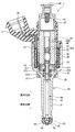
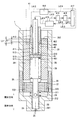
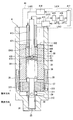
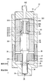
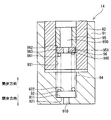
- FIG. 1 is a cross-sectional view of a fuel injection valve according to a first embodiment of the present disclosure
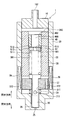
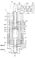
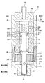
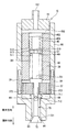
- FIG. 2 is a schematic diagram of a fuel injection valve according to the first embodiment of the present disclosure
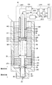
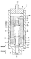
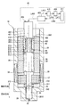
- FIG. 3 is a schematic diagram in the middle of manufacturing the fuel injection valve for explaining an adjustment method for adjusting the biasing force of the spring of the fuel injection valve according to the first embodiment of the present disclosure
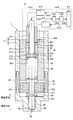
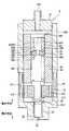
- FIG. 4 is a schematic diagram in the process of manufacturing the fuel injection valve for explaining the adjustment method for adjusting the biasing force of the spring of the fuel injection valve according to the first embodiment of the present disclosure, and the state is different from FIG. 3.
- FIG. 5 is a schematic diagram in the process of manufacturing the fuel injection valve for explaining an adjustment method for adjusting the biasing force of the spring of the fuel injection valve according to the first embodiment of the present disclosure.
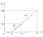
- FIG. 6 is a characteristic diagram showing the relationship between the position of the adjusting pipe of the fuel injection valve and the biasing force of the spring according to the first embodiment of the present disclosure
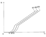
- FIG. 7 is a characteristic diagram showing the relationship between the time from the fuel injection start command and the fuel injection amount in the fuel injection valve according to the first embodiment of the present disclosure
- FIG. 8 is a schematic diagram illustrating an adjustment method for adjusting the biasing force of the spring of the fuel injection valve according to the second embodiment of the present disclosure.
- FIG. 6 is a characteristic diagram showing the relationship between the position of the adjusting pipe of the fuel injection valve and the biasing force of the spring according to the first embodiment of the present disclosure
- FIG. 7 is a characteristic diagram showing the relationship between the time from the fuel injection start command and the fuel injection amount in the fuel injection valve according to the first embodiment of the present
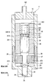
- FIG. 9 is a schematic diagram of a fuel injection valve according to the third embodiment of the present disclosure
- FIG. 10 is a schematic diagram of a fuel injection valve according to the fourth embodiment of the present disclosure
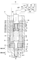
- FIG. 11 is a schematic diagram of a fuel injection valve manufacturing apparatus according to a fifth embodiment of the present disclosure
- FIG. 12 is a schematic diagram illustrating an adjustment method for a fuel injection valve manufacturing apparatus according to a sixth embodiment of the present disclosure
- FIG. 13 is a schematic diagram of a fuel injection valve according to a seventh embodiment of the present disclosure
- FIG. 14 is a schematic diagram of a fuel injection valve according to an eighth embodiment of the present disclosure
- FIG. 15 is a schematic diagram of a fuel injection valve according to the ninth embodiment of the present disclosure
- FIG. 16 is a schematic diagram of a fuel injection valve according to a tenth embodiment of the present disclosure
- FIG. 17 is a schematic diagram in the middle of manufacturing of the fuel injection valve for explaining an adjustment method for adjusting the biasing force of the spring of the fuel injection valve according to the tenth embodiment of the present disclosure
- FIG. 18 is a schematic diagram in the middle of manufacturing the fuel injection valve for explaining the adjustment method for adjusting the biasing force of the spring of the fuel injection valve according to the tenth embodiment of the present disclosure, and the state is different from FIG.
- FIG. 19 is a schematic diagram in the course of manufacturing the fuel injection valve for explaining an adjustment method for adjusting the biasing force of the spring of the fuel injection valve according to the tenth embodiment of the present disclosure.
- FIG. 20 is a schematic diagram of a fuel injection valve according to the eleventh embodiment of the present disclosure
- 21 is a cross-sectional view taken along line XXI-XXI in FIG.
- FIG. 22 is a schematic diagram of a fuel injection valve according to a twelfth embodiment of the present disclosure
- FIG. 23 is a schematic diagram of a valve device according to a fourteenth embodiment of the present disclosure
- FIG. 24 is a schematic diagram of a fuel injection valve according to a fifteenth embodiment of the present disclosure.
- First embodiment 1 and 2 show a fuel injection valve 1 as a valve device according to a first embodiment of the present disclosure. 1 and 2 illustrate a valve opening direction in which the needle 30 is separated from the valve seat 26 and a valve closing direction in which the needle 30 is in contact with the valve seat 26.
- the fuel injection valve 1 is used, for example, in a fuel injection device of a direct injection gasoline engine (not shown), and injects and supplies gasoline as fuel to the engine at a high pressure.
- the fuel injection valve 1 includes a housing 20 as a valve housing, a needle 30 as a valve member, a movable core 37, a fixed core 38 as a cylindrical member, a coil 39, a spring 28 as a biasing member, a spring 29, and an adjustment member. Adjusting pipe 40, intermediate member 51, and the like.
- the housing 20 includes a first cylinder member 21, a second cylinder member 22, a third cylinder member 23, and an injection nozzle 24.
- the first cylinder member 21, the second cylinder member 22, and the third cylinder member 23 are all formed in a substantially cylindrical shape, and are coaxial in the order of the first cylinder member 21, the second cylinder member 22, and the third cylinder member 23. Arranged and connected to each other.
- the injection nozzle 24 is provided at the end of the first cylinder member 21 opposite to the second cylinder member 22.
- the injection nozzle 24 is formed in a bottomed cylindrical shape.
- the injection nozzle 24 has an injection hole 25 as a hole communicating the inside and the outside of the housing 20 at the bottom.
- a valve seat 26 is formed around the inside of the injection hole 25.
- the needle 30 is formed of a shaft portion 31, a seal portion 32, a flange portion 33, and the like.
- the shaft portion 31, the seal portion 32, and the flange portion 33 are integrally formed.
- the shaft portion 31 is formed in a cylindrical rod shape.
- the shaft portion 31 has a passage 311 at an end portion on the fixed core 38 side.
- the passage 311 communicates with the inside of the fixed core 38.
- the passage 311 communicates with the nozzle hole 25 side of the movable core 37 through a through hole 312 that penetrates the shaft portion 31 in the radial direction.
- the seal portion 32 is provided at an end portion of the shaft portion 31 on the nozzle hole 25 side.
- the seal portion 32 can contact the valve seat 26.
- the flange portion 33 is provided on the radially outer side of the end portion of the shaft portion 31 opposite to the seal portion 32.
- the end surface of the flange portion 33 on the nozzle hole 25 side is in contact with the movable core 37.
- the needle 30 reciprocates inside the housing 20.
- the needle 30 opens and closes the nozzle hole 25 when the seal portion 32 is separated from the valve seat 26 or the seal portion 32 abuts on the valve seat 26, and communicates or blocks the inside and the outside of the housing 20.
- the movable core 37 is formed in a substantially cylindrical shape, and is provided on the nozzle hole 25 side of the flange portion 33.
- the movable core 37 is subjected to a magnetic stabilization process.
- a through hole 371 is formed in the approximate center of the movable core 37.
- the shaft portion 31 of the needle 30 is inserted into the through hole 371.
- a passage 372 that connects the fixed core 38 side of the movable core 37 and the injection hole 25 side is formed in the radially outward direction of the through hole 371.
- the fixed core 38 is formed in a substantially cylindrical shape, and is provided on the side opposite to the injection hole 25 of the movable core 37.
- the fixed core 38 is subjected to a magnetic stabilization process.
- the fixed core 38 is welded to the third cylinder member 23 of the housing 20 and is fixed to the inside of the housing 20.
- the coil 39 is formed in a substantially cylindrical shape and is provided so as to mainly surround the radially outer sides of the second cylinder member 22 and the third cylinder member 23.
- the coil 39 generates a magnetic field when electric power is supplied.
- a magnetic field is generated around the coil 39, a magnetic circuit is formed in the fixed core 38, the movable core 37, the first cylinder member 21, the third cylinder member 23, and the holder 19.
- a magnetic attractive force is generated between the fixed core 38 and the movable core 37, and the movable core 37 is attracted to the fixed core 38.
- the needle 30 in contact with the end surface of the movable core 37 opposite to the valve seat 26 moves together with the movable core 37 in the stationary core 38 side, that is, in the valve opening direction.
- the spring 28 is a compression spring, and is provided so that the first end is in contact with the end surface of the flange portion 33 opposite to the nozzle hole 25. The second end of the spring 28 is in contact with the intermediate member 51.
- the spring 28 has a force extending in the axial direction. The spring 28 urges the needle 30 together with the movable core 37 in the direction of the valve seat 26, that is, in the valve closing direction.
- the spring 29 is a compression spring, and the first end is provided so as to contact the end surface of the movable core 37 on the injection hole 25 side. The second end of the spring 29 is in contact with the inner wall 211 of the first cylinder member 21.
- the spring 29 has a force extending in the axial direction. The spring 29 urges the movable core 37 together with the needle 30 in the direction opposite to the valve seat 26, that is, in the valve opening direction.
- the urging force of the spring 28 is set larger than the urging force of the spring 29.
- the adjusting pipe 40 is a cylindrical member provided inside the fixed core 38.
- the adjusting pipe 40 is formed so that the outer diameter is equal to the inner diameter of the fixed core 38.
- the adjusting pipe 40 is press-fitted and fixed inside the fixed core 38.
- the adjusting pipe 40 has one communication path 400 that communicates the opposite side of the adjusting pipe 40 from the injection hole 25 and the injection hole 25 side at substantially the center.
- the intermediate member 51 is provided between the adjusting pipe 40 and the spring 28.
- the end surface 511 of the intermediate member 51 on the nozzle hole 25 side is in contact with the second end of the spring 28.
- An end surface 512 of the intermediate member 51 opposite to the injection hole 25 is in contact with an end surface 401 of the adjusting pipe 40 on the injection hole 25 side.
- a gap is formed between the radially outer outer wall 513 of the intermediate member 51 and the radially inner wall 381 of the fixed core 38. Thereby, the intermediate member 51 can be moved relative to the fixed core 38.
- the intermediate member 51 has a communication hole 510 that communicates the opposite side to the injection hole 25 and the injection hole 25 side.
- a substantially cylindrical fuel introduction pipe 16 is press-fitted and welded to the end of the third cylinder member 23 opposite to the second cylinder member 22.
- a filter 161 is provided inside the fuel introduction pipe 16. The filter 161 collects foreign matter contained in the fuel that has flowed from the introduction port 162 of the fuel introduction pipe 16.
- the radially outer sides of the fuel introduction pipe 16 and the third cylinder member 23 are molded with resin.
- a connector 17 is formed in the mold part.
- the connector 17 is insert-molded with a terminal 18 for supplying electric power to the coil 39.
- a cylindrical holder 19 is provided outside the coil 39 in the radial direction so as to cover the coil 39.
- a part of the fuel flowing from the introduction port 162 of the fuel introduction pipe 16 is inside the fixed core 38, the communication path 400, the communication hole 510, the path 311, the communication hole 312, and the shaft of the first cylindrical member 21 and the needle 30. It flows through the gap between the portions 31 and is guided into the injection nozzle 24. Further, a part of the fuel flowing in from the introduction port 162 is inside the fixed core 38, the communication path 400, the communication hole 510, the flange 33 and the fixed core 38, the path 372, and the first cylinder member 21. It flows through the gap between the shaft portion 31 of the needle 30 and is guided to the inside of the injection nozzle 24. That is, a fuel passage for introducing fuel into the injection nozzle 24 extends from the introduction port 162 of the fuel introduction pipe 16 to the gap between the first cylindrical member 21 and the shaft portion 31 of the needle 30.
- FIG. 6 shows the relationship between the position of the adjusting pipe 40 and the biasing force of the spring 28.
- the horizontal axis in FIG. 6 shows the position of the adjusting pipe 40 with respect to the fixed core 38. Specifically, the distance L from the end surface 382 opposite to the injection hole 25 of the fixed core 38 to the end surface 402 of the adjusting pipe 40 in the direction of the central axis CA1 is shown. That is, when the end surface 382 and the end surface 402 are on the same plane, the distance L is zero. Further, when the adjusting pipe 40 moves in the valve closing direction from the position where the distance L is 0, the distance L becomes positive.
- the configuration of the urging force adjusting device 41 as a valve device manufacturing device used in the adjustment process of the urging force of the spring 28 will be described.
- the urging force adjusting device 41 includes a first jig 411, a second jig 412, a first drive unit 413 that drives the first jig 411, a second drive unit 414 that drives the second jig 412, and a detection unit 415. , A calculation unit 416, and a control unit 417 for controlling two driving units.
- the first jig 411 is a substantially rod-shaped member.
- the first jig 411 is connected to the first drive unit 413 (a chain line L411 in FIG. 3).
- the first jig 411 can reciprocate in the direction of the central axis CA1 of the fuel injection valve 1.
- the first jig 411 can abut on the end surface 512 of the intermediate member 51 via the communication path 400.
- the second jig 412 is a substantially cylindrical member provided on the outer side in the radial direction of the first jig 411.
- tool 412 is connected with the 2nd drive part 414 (dashed line L412 of FIG. 3).
- the second jig 412 can reciprocate in the direction of the central axis CA1 of the fuel injection valve 1.
- the second jig 412 can abut on the end surface 402 of the adjusting pipe 40 opposite to the nozzle hole 25.
- the detection unit 415 is electrically connected to the first drive unit 413 (two-dot chain line L415 in FIG. 3).
- the detection unit 415 detects the biasing force of the spring 28 based on the acting force from the spring 28 acting on the first jig 411 when the first driving unit 413 drives the first jig 411 to the nozzle hole 25 side. .
- the detection unit 415 detects the moving distance of the first jig 411.
- the detection unit 415 outputs a signal corresponding to the detected magnitude of the biasing force of the spring 28 and the movement distance of the first jig 411 to the calculation unit 416.
- the calculation unit 416 is electrically connected to the detection unit 415 (two-dot chain line L416 in FIG. 3).
- the calculation unit 416 determines whether the biasing force of the spring 28 is a predetermined biasing force based on a signal corresponding to the magnitude of the biasing force of the spring 28 output from the detection unit 415 and the moving distance of the first jig 411.
- the pipe set position as the adjustment member set position of the adjusting pipe 40 that becomes the urging force Fsp3 is calculated.
- the calculation unit 416 outputs a signal corresponding to the pipe set position to the control unit 417.
- the control unit 417 is electrically connected to the first drive unit 413, the second drive unit 414, and the calculation unit 416 (two-dot chain lines L413, L414, and L417 in FIG. 3).
- the control unit 417 outputs a first control signal to the first drive unit 413 and controls the reciprocation of the first jig 411.
- the control unit 417 outputs a signal corresponding to the pipe set position to the second drive unit 414 to control the reciprocation of the second jig 412.
- the spring 28 is assembled to the fuel injection valve 1 to which the fuel introduction pipe 16 is not assembled.
- the intermediate member 51 and the adjusting pipe 40 are inserted into the fixed core 38. Since the outer diameter of the intermediate member 51 is smaller than the inner diameter of the fixed core 38, the intermediate member 51 can freely reciprocate in the direction of the central axis CA1. The intermediate member 51 inserted into the fixed core 38 abuts on the second end of the spring 28.
- the adjusting pipe 40 Since the adjusting pipe 40 has an outer diameter equal to the inner diameter of the fixed core 38, the adjusting pipe 40 is press-fitted into the fixed core 38 by pressing the second jig 412. The first jig 411 is kept in contact with the intermediate member 51 until the adjusting pipe 40 to be pressed contacts the intermediate member 51 (the distance L in FIG. 5 is from 0 to L1). ing. Since the length of the spring 28 at this time is a natural length, the biasing force of the spring 28 detected by the detection unit 415 is zero.
- the adjusting pipe 40 comes into contact with the intermediate member 51 (see FIG. 4). Thereafter, the intermediate member 51 and the adjusting pipe 40 are moved in the valve closing direction by the first jig 411 and the second jig 412 while the adjusting pipe 40 and the intermediate member 51 are kept in contact with each other. At this time, the detection unit 415 detects the biasing force of the spring 28 according to the distance L.
- the calculation unit 416 calculates the distance L and the spring 28 based on the biasing force of the spring 28 detected by the detection unit 415. Is derived from the urging force Fsp (solid line portion FL1 between the distance L1 and the distance L2 in FIG. 6). The distance that the adjusting pipe 40 can move before the relationship between the distance L and the urging force Fsp is derived is a distance calculated in advance so that the urging force of the spring 28 is smaller than the target urging force Fsp3. Let L2.
- the calculation unit 416 calculates a distance L3 from the end surface 382 to the end surface 402 when the biasing force of the spring 28 becomes the target biasing force Fsp3 based on the relationship between the derived distance L and the biasing force Fsp (FIG. 6 is a dotted line portion FL2 between a distance L2 and a distance L3). That is, in the fuel injection valve 1, the pipe set position of the adjusting pipe 40 is a position where the distance from the end surface 382 to the end surface 402 is the distance L3.
- the control unit 417 causes the second drive unit 414 to perform the second treatment so that the distance from the end surface 382 to the end surface 402 becomes the distance L3.
- the tool 412 is pushed in the valve closing direction (see FIG. 5).
- the adjustment process of the biasing force of the spring 28 is finished.
- the horizontal axis indicates time Ti from the fuel injection start command
- the vertical axis indicates the fuel injection amount Qi of the fuel injection valve 1.
- the origin of the horizontal axis is when power supply to the coil 39 is started.
- the needle 30 is separated from the valve seat 26 and opened after a certain amount of time has elapsed since the supply of power to the coil 39 was started.
- the valve opening behavior of the fuel injection valve 1 is determined by the suction force between the movable core 37 and the fixed core 38 that drive the needle 30 in the valve opening direction, and the biasing force of the springs 28 and 29 that bias the needle 30. Determined by balance.
- the urging force of the spring 28 is determined by the pipe set position of the adjusting pipe 40 that is press-fitted into the fixed core 38.
- the time when the fuel injection valve 1 starts fuel injection changes.
- the adjusting pipe 40 is not sufficiently press-fitted and the pipe set position is shallow, that is, at a position relatively close to the fuel introduction pipe 16, the biasing force of the spring 28 becomes smaller than the target biasing force. Therefore, fuel injection is started at time T1 earlier than time T0, which is the target fuel injection start timing, and the fuel injection amount is as indicated by a two-dot chain line QT1.
- the adjusting pipe 40 is press-fitted deep into the fixed core 38 and the pipe set position is deep, that is, close to the needle 30, the biasing force of the spring 28 becomes larger than the target biasing force. For this reason, fuel injection is started at time T2 later than the target time T0, and the fuel injection amount is as indicated by a two-dot chain line QT2.
- an intermediate member 51 capable of detecting the biasing force of the spring 28 without being influenced by the press-fit state of the adjusting pipe 40 is provided between the adjusting pipe 40 and the spring 28. ing.
- the relationship between the position of the adjusting pipe 40 and the biasing force of the spring 28 is derived. Based on the derived relationship, the pipe set position of the adjusting pipe that uses the biasing force of the spring 28 as a target biasing force is calculated.
- the adjusting pipe 40 is fixed to the calculated pipe set position. Therefore, the fuel injection valve 1 can set the biasing force of the spring 28 with high accuracy. Therefore, the time from when the supply of electric power to the coil 39 is started to when the fuel injection is actually started can be set with high accuracy.
- the biasing force of the spring 28 can be set with high accuracy, the biasing force of the spring 28 can be set as the target biasing force by dry adjustment that does not actually inject the fluid. it can. Thereby, the fuel injection valve 1 can shorten the time which adjusts urging
- FIG. 8 shows an urging force adjusting device 42 as a valve device manufacturing apparatus according to the second embodiment.
- the urging force adjusting device 42 includes a first jig 411, a second jig 412, a first drive unit 413, a second drive unit 414, a detection unit 415, a storage unit 426, a control unit 417, and the like. .
- the storage unit 426 is electrically connected to the detection unit 415 and the control unit 417 (two-dot chain lines L426 and L417 in FIG. 8).
- the storage unit 426 stores the movement distance of the intermediate member 51 when the biasing force of the spring 28 becomes the target biasing force Fsp3.
- the storage unit 426 outputs a signal corresponding to the stored movement distance to the control unit 417.
- the intermediate member 51 and the adjusting pipe 40 are inserted into the fuel injection valve 1 to which the spring 28 is assembled. At this time, the adjusting pipe 40 moves the distance L ⁇ b> 1 so as to contact the intermediate member 51 that is in contact with the spring 28 by pressing the second jig 412.
- the detecting member 415 pushes the intermediate member 51 toward the nozzle hole 25 by the first jig 411 while detecting the urging force of the spring 28. At this time, the intermediate member 51 is pushed in until the biasing force of the spring 28 acting on the intermediate member 51 becomes the target biasing force Fsp3 (see FIG. 8).
- the storage unit 426 included in the biasing force adjusting device 42 has an intermediate member set position where the biasing force of the spring 28 acting on the intermediate member 51 becomes the target biasing force Fsp3 from the position where the adjusting pipe 40 and the intermediate member 51 abut.
- the distance of movement of the intermediate member 51 to the intermediate set position that is, the distance (L3-L1) is stored.
- the control unit 417 drives the second jig 412 and moves the adjusting pipe 40 by the distance (L3-L1). Push in.
- the adjusting pipe 40 is fixed at a pipe set position where the biasing force of the spring 28 becomes the target biasing force Fsp3.
- the urging force adjusting device 42 uses the first jig 411 that can detect the urging force of the spring 28, and the distance at which the urging force of the spring 28 first becomes the target urging force Fsp3. (L3-L1) is stored. Thereafter, the adjusting pipe 40 is moved by a distance (L3-L1). Thereby, the biasing force of the spring 28 can be set with high accuracy.
- FIG. 3 a valve device according to a third embodiment of the present disclosure will be described based on FIG.
- the third embodiment is different from the first embodiment in the shape of the intermediate member.
- symbol is attached
- FIG. 9 shows a fuel injection valve 3 as a valve device according to the third embodiment.
- the intermediate member 56 provided in the fuel injection valve 3 is provided between the adjusting pipe 40 and the spring 28.
- the intermediate member 56 has a communication hole 560 that communicates the opposite side to the injection hole 25 and the injection hole 25 side.
- the inner diameter of the communication hole 560 is smaller than the inner diameter of the communication hole 510 included in the intermediate member 51 of the first embodiment.
- the inner diameter of the communication hole 560 of the intermediate member 56 is relatively small. Accordingly, the communication hole 560 functions as an orifice with respect to the fuel flow inside the fuel injection valve 3, and the fuel flowing from the communication path 400 to the injection hole 25 side of the intermediate member 56 can be throttled. Thereby, the pressure pulsation inside the fuel injection valve 3 can be reduced.
- the fourth embodiment differs from the first embodiment in the shape of the intermediate member.
- symbol is attached
- FIG. 10 shows a fuel injection valve 4 as a valve device according to the fourth embodiment.
- the intermediate member 61 provided in the fuel injection valve 4 is provided between the adjusting pipe 40 and the spring 28.
- the intermediate member 61 has a communication hole 610 that communicates the opposite side to the injection hole 25 and the injection hole 25 side.
- the inner edge of the communication hole 610 opposite to the injection hole 25 has an inner edge slope 611 formed so as to be away from the central axis CA 610 of the communication hole 610 from the injection hole 25 side toward the opposite side of the injection hole 25.
- the fuel introduced into the housing 20 through the inlet 162 flows from the side having the inner edge slope 611 toward the injection hole 25. At this time, the fuel can smoothly flow into the communication hole 610 by the inner edge slope 611. Thereby, the resistance of the fuel which acts on the intermediate member 61 can be reduced, and the intermediate member 61 can be prevented from being displaced toward the nozzle hole 25 side. Therefore, it is possible to prevent the biasing force of the spring 28 from changing due to the flow of fuel.
- the fifth embodiment differs from the fourth embodiment in the shape of the first jig.
- symbol is attached
- FIG. 11 shows an urging force adjusting device 43 as a valve device manufacturing apparatus according to the fifth embodiment.
- the urging force adjusting device 43 includes a first jig 431, a second jig 412, a first drive unit 413 that drives the first jig 431, a second drive unit 414, a detection unit 415, a calculation unit 416, and a control. It consists of part 417 and the like.
- the first jig 431 is formed in a substantially rod shape.
- the first jig 431 is connected to the first drive unit 413 (a chain line L431 in FIG. 11).
- the first jig 431 has a tip slope 432 at the outer edge of the end that can contact the intermediate member 61.
- the tip slope 432 is formed so as to move away from the central axis CA43 of the first jig 431 from the side contacting the intermediate member 61 toward the side opposite to the side contacting the intermediate member 61.
- the tip slope 432 of the first jig 431 can contact the inner edge slope 611 of the intermediate member 61. Therefore, the centering of the first jig 431 with respect to the intermediate member 61 can be easily performed. Therefore, the biasing force of the spring 28 can be set with higher accuracy.
- FIG. 12 shows an urging force adjusting device 44 as a valve device manufacturing apparatus according to the sixth embodiment.
- the urging force adjusting device 44 includes a first jig 441, a second jig 412, a first drive unit 413 that drives the first jig 441, a second drive unit 414, a detection unit 415, a calculation unit 416, and a control. It consists of part 417 and the like.
- the first jig 441 is formed in a substantially rod shape.
- the first jig 441 is connected to the first drive unit 413 (a chain line L441 in FIG. 12).
- an outer wall 442 at the end that can come into contact with the intermediate member 61 is formed in a spherical shape.
- the outer wall 442 of the first jig 431 can come into contact with the inner edge slope 611 of the intermediate member 61. Thereby, the centering of the first jig 441 with respect to the intermediate member 61 can be easily performed. Therefore, the biasing force of the spring 28 can be set with higher accuracy.
- valve device according to a seventh embodiment of the present disclosure will be described with reference to FIG.
- the seventh embodiment differs from the first embodiment in the shape of the intermediate member.
- symbol is attached
- FIG. 13 shows a fuel injection valve 7 as a valve device according to the seventh embodiment.
- the intermediate member 66 provided in the fuel injection valve 7 is formed of a contact portion 661 and a protrusion 662 as a first protrusion.
- the intermediate member 66 has a communication hole 660 that passes through the contact portion 661 and the protrusion 662 and communicates the opposite side of the intermediate member 66 from the injection hole 25 and the injection hole 25 side.
- the abutting portion 661 is provided between the adjusting pipe 40 and the spring 28.
- the end surface 663 on the injection hole 25 side is in contact with the second end of the spring 28.
- An end surface 664 of the contact portion 661 opposite to the nozzle hole 25 is in contact with the end surface 401 of the adjusting pipe 40.
- a gap is formed between the radially outer outer wall 665 of the contact portion 661 and the radially inner wall 381 of the fixed core 38.
- the protrusion 662 is formed so as to protrude from the end surface 663 of the contact portion 661 toward the injection hole 25.
- the protrusion 662 is inserted into the second end of the spring 28 that is in contact with the contact portion 661.
- the protrusion 662 inserted into the second end of the spring 28 can guide the expansion and contraction movement of the spring 28. Thereby, the biasing force of the spring 28 can be stabilized.
- valve device according to an eighth embodiment of the present disclosure will be described with reference to FIG.
- the eighth embodiment differs from the first embodiment in the shape of the intermediate member.
- symbol is attached
- FIG. 14 shows a fuel injection valve 8 as a valve device according to the eighth embodiment.
- the intermediate member 71 provided in the fuel injection valve 8 is formed of a contact portion 711 and a protrusion 712 as a second protrusion.
- the intermediate member 71 has a communication hole 710 that passes through the contact portion 711 and the protrusion 712 and communicates the opposite side of the intermediate member 71 from the injection hole 25 and the injection hole 25 side.
- the abutting portion 711 is provided between the adjusting pipe 40 and the spring 28.
- the end surface 713 on the injection hole 25 side is in contact with the second end of the spring 28.
- An end surface 714 of the contact portion 711 opposite to the nozzle hole 25 is in contact with an end surface 401 of the adjusting pipe 40 on the nozzle hole 25 side.
- a gap is formed between the radially outer outer wall 715 of the contact portion 711 and the radially inner wall 381 of the fixed core 38.
- the protrusion 712 is formed so as to protrude from the end surface 714 of the contact portion 711 to the side opposite to the injection hole 25.
- the protrusion 712 is inserted into the communication path 400 of the adjusting pipe 40.
- the radial alignment between the adjusting pipe 40 and the intermediate member 71 can be performed by the protrusion 712 inserted into the communication path 400. Thereby, the relative position of the radial direction of the adjusting pipe 40 and the intermediate member 71 can be stabilized.
- FIG. 15 shows a fuel injection valve 9 as a valve device according to the ninth embodiment.
- the intermediate member 76 provided in the fuel injection valve 9 is formed of a contact portion 761 and a protrusion 762 as a second protrusion.
- the intermediate member 76 has a communication hole 760 that passes through the contact portion 761 and the protrusion 762 and communicates the opposite side of the intermediate member 76 from the injection hole 25 and the injection hole 25 side.
- the abutting portion 761 is provided between the adjusting pipe 40 and the spring 28.
- the end surface 763 on the nozzle hole 25 side is in contact with the second end of the spring 28.
- An end surface 764 of the contact portion 761 opposite to the nozzle hole 25 is in contact with an end surface 401 of the adjusting pipe 40 on the nozzle hole 25 side.
- a gap is formed between the outer wall 765 on the radially outer side of the contact portion 761 and the inner wall 381 on the radially inner side of the fixed core 38.
- the protrusion 762 is formed so as to protrude from the end surface 764 of the contact portion 761 to the side opposite to the injection hole 25.
- the outer edge portion of the protrusion 762 opposite to the nozzle hole 25 has an outer edge slope 766 that approaches the central axis CA762 of the protrusion 762 from the nozzle hole 25 side toward the opposite side of the nozzle hole 25.
- the protrusion 762 is located in the communication path 400 of the adjusting pipe 40.
- the tenth embodiment differs from the first embodiment in the shapes of the intermediate member, the first jig, and the second jig.
- symbol is attached
- FIG. 16 shows a fuel injection valve 10 as a valve device according to the tenth embodiment.
- the intermediate member 81 included in the fuel injection valve 10 is formed of a contact portion 811 and a protrusion 812 as a second protrusion.
- the intermediate member 81 has a communication hole 810 that passes through the contact portion 811 and the protrusion 812 and communicates the side opposite to the injection hole 25 of the intermediate member 71 and the injection hole 25 side.
- the abutting portion 811 is provided between the adjusting pipe 40 and the spring 28.
- the end surface 813 on the injection hole 25 side is in contact with the second end of the spring 28.
- An end surface 814 opposite to the nozzle hole 25 of the contact portion 811 is in contact with the end surface 401 of the adjusting pipe 40.
- a gap is formed between the outer wall 815 on the radially outer side of the contact portion 811 and the inner wall 381 on the radially inner side of the fixed core 38.
- the protrusion 812 is formed so as to protrude from the end surface 814 of the contact portion 811 to the side opposite to the injection hole 25.
- the protrusion 812 is inserted into the communication path 400 of the adjusting pipe 40.
- the protrusion 812 is formed so as to protrude from the end surface 402 of the adjusting pipe 40 toward the fuel introduction pipe 16.
- the urging force adjusting device 45 that adjusts the urging force of the spring 28 included in the fuel injection valve 10 includes a common jig 450, a common drive unit 455 that drives the common jig 450, a detection unit 415, a calculation unit 416, and a common drive unit 455. It is comprised from the control part 417 etc. which control.
- the common jig 450 is formed of a first part 451 as a first jig and a second part 452 as a second jig. That is, in the common jig 450, the first jig and the second jig are integrally formed.
- the first portion 451 can abut on the end surface 816 on the opposite side of the projection 812 from the nozzle hole 25.
- the second part 452 is provided on the outer side in the radial direction of the first part 451, and can contact the end surface 402 of the adjusting pipe 40.
- the end face 453 of the first part 451 on the nozzle hole 25 side and the end face 454 of the second part 452 on the nozzle hole 25 side are formed on the same plane.
- the common drive unit 455 is connected to the common jig 450 (chain line L450 in FIGS. 17 to 19).
- the common drive unit 455 is electrically connected to the control unit 417 (two-dot chain line L455 in FIGS. 17 to 19).
- the common drive unit 455 reciprocates the common jig 450 in the direction of the central axis CA10 of the fuel injection valve 10 based on a control signal output from the control unit 417.
- the common jig 450 is brought into contact with the end surface 816 of the protrusion 812 (see FIG. 17).
- the calculation unit 416 determines the moving distance of the intermediate member 81 and the biasing force of the spring 28 based on the biasing force of the spring 28 detected by the detection unit 415 until the common jig 450 contacts the adjusting pipe 40.
- the relationship with Fsp is derived.
- the calculation unit 416 calculates a distance L3 from the end surface 382 to the end surface 402 when the biasing force of the spring 28 becomes the target biasing force Fsp3 based on the relationship between the derived movement distance of the intermediate member 81 and the biasing force Fsp. calculate.
- the control unit 417 When the common jig 450 and the adjusting pipe 40 come into contact with each other (see FIG. 18), the control unit 417 further moves the common jig 450 by the common driving unit 455 so that the distance from the end surface 382 to the end surface 402 becomes the distance L3. Push into the nozzle hole 25 side. When the distance from the end surface 382 to the end surface 402 becomes the distance L3, the adjustment process of the biasing force of the spring 28 is ended (see FIG. 19). At this time, the intermediate member 81 is pushed so that the urging force of the spring 28 is greater than the urging force Fsp3.
- the urging force adjusting device 45 pushes the adjusting pipe 40 and the intermediate member 81 into the fixed core 38 by using one common jig 450, and the urging force Fsp3 aimed at the urging force of the spring 28.
- the adjusting pipe 40 and the intermediate member 81 can be provided. Thereby, the structure of the urging
- the eleventh embodiment differs from the first embodiment in the shape of the adjusting pipe.
- symbol is attached
- FIG. 20 shows a fuel injection valve 11 as a valve device according to the eleventh embodiment.
- the adjusting pipe 50 provided in the fuel injection valve 11 has a plurality of communication passages 500 at the outer edge. As shown in FIG. 21, the communication path 500 is formed by cutting an outer edge portion radially inward. The communication passage 500 is formed at equal intervals in the circumferential direction of the adjusting pipe 50. In the eleventh embodiment, the adjusting pipe 50 has four communication passages 500. The communication path 500 communicates the side opposite to the injection hole 25 of the adjusting pipe 50 and the injection hole 25 side.
- the biasing force of the spring 28 when the biasing force of the spring 28 is adjusted using the biasing force adjusting device 41, the first jig 411 can be brought into contact with the intermediate member 51 using the communication path 500. Thereby, the biasing force of the spring 28 can be set with high accuracy.
- the twelfth embodiment differs from the first embodiment in that an O-ring is provided on the radially outer side of the intermediate member.
- symbol is attached
- FIG. 22 shows a fuel injection valve 12 as a valve device according to the twelfth embodiment.
- the intermediate member 86 provided in the fuel injection valve 12 is provided between the adjusting pipe 40 and the spring 28.
- An end surface 861 on the nozzle hole 25 side of the intermediate member 86 is in contact with the second end of the spring 28.
- An end surface 862 of the intermediate member 86 opposite to the injection hole 25 is in contact with an end surface 401 of the adjusting pipe 40 on the injection hole 25 side.
- the intermediate member 86 has a communication hole 860 that communicates the opposite side to the injection hole 25 and the injection hole 25 side.
- the outer wall 863 on the radially outer side of the intermediate member 86 has a groove 864 that is recessed in the radial direction.
- the groove 864 is provided with an O-ring 87 as an expansion member.
- the O-ring 87 forms a gap with the inner wall 381 of the fixed core 38 before coming into contact with the fuel, but expands when coming into contact with the fuel and comes into contact with the inner wall 381. Thereby, the intermediate member 86 cannot be moved relative to the fixed core 38.
- the biasing force of the spring 28 is adjusted using the biasing force adjusting device 41. At this time, since the biasing force of the spring 28 is adjusted by dry adjustment without flowing fuel, the fuel does not flow inside the fuel injection valve 12. Thereby, since the O-ring 87 is not in contact with fuel, a gap is formed between the O-ring 87 and the fixed core 38, and the intermediate member 86 can move relative to the fixed core 38. In the fuel injection valve 12, the biasing force of the spring 28 can be detected with high accuracy via the relatively movable intermediate member 86.
- the fuel injection valve 12 can set the biasing force of the spring 28 with high accuracy at the time of manufacture, and can prevent the biasing force of the spring 28 from changing due to the flow of fuel during actual use.
- the thirteenth embodiment differs from the first embodiment in the material for forming the intermediate member and the method for adjusting the biasing force of the spring.
- symbol is attached
- the intermediate member 51 provided in the fuel injection valve according to the thirteenth embodiment is formed of a material having a large volume change rate due to a temperature change.
- the intermediate member 51 When adjusting the biasing force of the spring 28 provided in the fuel injection valve, the intermediate member 51 is first cooled and contracted. In this state, since the intermediate member 51 can move relative to the fixed core 38, the biasing force of the spring 28 can be accurately detected via the intermediate member 51.
- the fuel injection valve according to the thirteenth embodiment can set the biasing force of the spring 28 with high accuracy during manufacture and can prevent the biasing force of the spring 28 from changing due to the flow of fuel during actual use. .
- the fourteenth embodiment differs from the first embodiment in that it does not include a drive unit that drives the needle in the valve opening direction.
- symbol is attached
- FIG. 23 shows the valve device 14 according to the fourteenth embodiment.
- the valve device 14 allows the flow of the high-pressure fluid from a high-pressure passage (not shown) through which the high-pressure fluid flows to a low-pressure passage (not shown) through which the low-pressure fluid can flow.
- the valve device 14 includes a housing 91 as a valve housing, a valve member 92, a cylindrical member 93, a spring 94 as a biasing member, an adjusting pipe 95 as an adjustment member, an intermediate member 96, and the like.
- FIG. 23 illustrates a valve opening direction in which the valve member 92 is separated from the valve seat 911 and a valve closing direction in which the valve member 92 is in contact with the valve seat 911.
- the housing 91 is formed in a substantially bottomed cylindrical shape.
- the bottom portion of the housing 91 has a hole 910 that communicates the inside and the outside of the housing 91.
- a valve seat 911 is formed around the inner side of the hole 910.
- the valve member 92 is a substantially disk-shaped member, and is provided so as to reciprocate within the housing 91.
- the end surface 921 on the hole 910 side of the valve member 92 can come into contact with the valve seat 911.
- the cylindrical member 93 is provided on the inner wall of the housing 91.
- the cylindrical member 93 is provided so as not to move relative to the housing 91.
- the spring 94 is provided such that the first end is in contact with the end surface 922 opposite to the hole 910 of the valve member 92.
- the second end of the spring 94 is in contact with the intermediate member 96.
- the spring 94 has a force extending in the axial direction. As a result, the spring 94 biases the valve member 92 in the direction of the valve seat 911, that is, in the valve closing direction.
- the adjusting pipe 95 is a cylindrical member.
- the adjusting pipe 95 is formed so that the outer diameter is equal to the inner diameter of the cylindrical member 93.
- the adjusting pipe 95 is press-fitted and fixed inside the cylindrical member 93.
- the adjusting pipe 95 has a communication passage 950 that communicates the side opposite to the hole 910 of the adjusting pipe 95 and the hole 910 side.
- the intermediate member 96 is provided between the adjusting pipe 95 and the spring 94.
- An end surface 961 on the hole 910 side of the intermediate member 96 is in contact with the second end of the spring 94.
- the end surface 962 of the intermediate member 96 opposite to the hole 910 is in contact with the end surface 951 of the adjusting pipe 95 on the hole 910 side.
- a gap is formed between the radially outer outer wall 963 of the intermediate member 96 and the radially inner wall 931 of the cylindrical member 93. Thereby, the intermediate member 96 can be moved relative to the cylindrical member 93.
- the intermediate member 96 has a communication hole 960 that communicates the opposite side to the hole 910 and the hole 910 side.
- the valve device 14 opens based on the magnitude relationship of the biasing force of the spring 94 with respect to the difference between the pressure of the high-pressure fluid flowing through the high-pressure passage and the pressure of the low-pressure fluid flowing through the low-pressure passage.
- the biasing force of the spring 94 is detected via the intermediate member 96. Based on the detection result, the pipe set position of the adjusting pipe 95 when the biasing force of the spring 94 becomes the target biasing force is calculated.
- the adjusting pipe 95 is moved and fixed to the calculated pipe set position. Thereby, the valve device 14 can set the biasing force of the spring 94 with high accuracy.
- the fifteenth embodiment differs from the first embodiment in the direction in which the needle moves when the valve is opened.
- symbol is attached
- FIG. 24 shows the valve device 15 according to the fifteenth embodiment.
- the valve device 15 is a so-called outer valve.
- the valve device 15 includes a housing 60 as a valve housing, a needle 70 as a valve member, a movable core 37, a fixed core 38, a coil 39, a spring 88 as a biasing member, a spring 89, an adjusting pipe 40, an intermediate member 51, and the like. Is provided.
- the housing 60 is formed in a bottomed cylindrical shape.
- the housing 60 has a hole 63 at the bottom for communicating the inside and outside of the housing 60. As shown in FIG. 24, the hole 63 is formed so that the inner diameter increases from the inside of the housing 60 toward the outside.
- a valve seat 64 is formed on the inner wall forming the hole 63.
- the needle 70 is formed of a shaft portion 31, a seal portion 72, a flange portion 33, and the like.
- the shaft portion 31, the seal portion 72, and the flange portion 33 are integrally formed.
- the seal portion 72 is formed in a substantially truncated cone shape, and is provided at the end portion of the shaft portion 31 on the hole 63 side.
- the conical surface 721 of the seal portion 72 is formed so as to be able to contact the valve seat 64.
- the needle 70 opens or closes the hole 63 when the conical surface 721 is separated from the valve seat 64 or abuts against the valve seat 64, thereby communicating or blocking the inside and outside of the housing 60.
- the spring 88 is provided so that the first end is in contact with the end surface 701 opposite to the hole 63 of the needle 70.
- the second end of the spring 88 is in contact with the end surface 511 of the intermediate member 51.
- the spring 88 has a force extending in the axial direction. Thereby, the spring 88 urges the needle 70 together with the movable core 37 in the valve opening direction.
- the spring 89 is provided such that the first end is in contact with the end surface of the movable core 37 on the hole 63 side.
- the second end of the spring 89 is in contact with the inner wall 601 of the housing 60.
- the spring 89 has a force extending in the axial direction. The spring 89 urges the movable core 37 together with the needle 70 in the valve closing direction.
- the valve device 15 is a so-called normally open type valve device that maintains a valve open state by the difference between the urging force of the spring 88 and the urging force of the spring 89 when electric power is not supplied to the coil 39.
- the biasing force of the spring 88 is detected via the intermediate member 51. Based on the detection result, the pipe set position of the adjusting pipe 40 when the biasing force of the spring 88 becomes the target biasing force is calculated. The adjusting pipe 40 is moved and fixed to the calculated pipe set position. Thereby, the valve apparatus 15 can set the biasing force of the spring 88 that biases the needle 70 in the valve opening direction with high accuracy.
- the fuel injection valve as the valve device includes the intermediate member.
- the valve device including the intermediate member described in the first to thirteenth embodiments is not limited to this.
- it may be a relief valve, or fluid flow from the second end to the first end while allowing fluid to flow from the first end to the second end. It may be a valve device that regulates distribution.
- an outer valve that closes when power is supplied may be used.
- the needle and the movable core are provided separately.
- the needle and the movable core may be provided integrally.
- the springs 29 and 89 that urge the movable core toward the intermediate member may be omitted.
- the fuel injection valve as the valve device includes a fixed core, a movable core, a coil, and the like as a cylindrical member, and opens when electric power is supplied.
- the valve device of the present disclosure may not be an electromagnetic valve that is opened by supplying electric power.
- it may be a valve device that opens by a pressure difference between fluids.
- the intermediate member provided in the fuel injection valve has a communication hole that functions as an orifice.
- the communication path functioning as the orifice may be provided by an intermediate member provided in the valve device according to the fourteenth embodiment or an intermediate member provided in the valve device according to the fifteenth embodiment.
- the intermediate member of the fourteenth embodiment has a communication passage having a relatively small inner diameter, cavitation can be prevented from occurring in the fluid flowing inside the valve housing.
- the inner edge of the intermediate member on the side opposite to the nozzle hole of the communication hole is formed so as to be separated from the central axis of the intermediate member as it goes from the nozzle hole side to the side opposite to the nozzle hole. It has an inner edge slope.
- the valve device of the third, seventh to fifteenth embodiments may be included.
- the intermediate member has a protrusion as the first protrusion.
- the intermediate member has a protrusion as the second protrusion.
- the intermediate member provided in the valve device of the present disclosure may have both the first protrusion and the second protrusion.
- the intermediate member can be moved relative to the fixed core by heating and expanding the fixed core when adjusting the biasing force of the spring, and the intermediate member can move relative to the fixed core by returning to normal temperature when actually used.
- the relative movement may be impossible.
- the intermediate member when adjusting the biasing force of the spring, the intermediate member is cooled while heating and expanding the fixed core so that the intermediate member can move relative to the fixed core.
- the fixed core and the intermediate member are at room temperature. The intermediate member may not be able to move relative to the fixed core by returning to step S2.
- the intermediate member can move relative to the fixed core even if the environmental temperature at which the fuel injection valve is used is lowered.
- the intermediate member contracts to the same extent by cooling, so that the intermediate member does not come off the fixed core. Thereby, it is possible to prevent the intermediate member from moving due to the resistance of the fuel introduced from the fuel introduction pipe.
- the adjusting pipe is assumed to have one communication passage in the center.
- the adjusting pipe has four notches radially outward. The position and the number of the cutouts are not limited to this. What is necessary is just to have the space which connects the opposite side to the nozzle hole of an adjusting pipe, and the nozzle hole side.
- the first jig and the second jig included in the biasing force adjusting device are separate members. It may be integral.
- the end portion of the first jig provided in the biasing force adjusting device on the side in contact with the intermediate member has a tip inclined surface or a spherical surface capable of contacting the inner edge inclined surface of the intermediate member.
- the first jig may have a tip slope or a spherical surface at an end on the side in contact with the intermediate member even if the intermediate member does not have an inner edge slope. Even in this case, it is possible to easily center the first jig with respect to the intermediate member.
- the urging force adjusting device includes a calculation unit.
- a storage unit may be provided instead of the calculation unit.
- the biasing force adjusting device includes a common jig in which the first jig and the second jig are integrated.
- the first jig and the second jig may be separate members.
- the present disclosure is not limited to such an embodiment, and can be implemented in various forms without departing from the gist thereof.
Abstract
This valve device is provided with: a valve housing (20, 60, 91) having a hole (25, 63, 910) through which a fluid can pass, and a valve seat (26, 64, 911) formed around the hole; a cylindrical member (38, 93) which is fixed inside the valve housing or is formed integrally with the valve housing; a valve member (30, 70, 92) which is provided in such a way as to be able to reciprocate within the valve housing, and which opens or closes the hole by moving away from the valve seat or coming into contact with the valve seat; an urging member (28, 88, 94), a first end of which is in contact with the valve member, and which is capable of urging the valve member in a valve closing direction or a valve opening direction; an intermediate member (51, 56, 61, 66, 71, 76, 81, 86, 96) which is in contact with a second end of the urging member; and an adjusting member (40, 50, 95) which is press-fitted and fixed inside the cylindrical member in such a way as to come into contact with the intermediate member on the opposite side thereof to the urging member, has a communication passage (400, 500, 950) communicating between a side of the adjusting member on the opposite side to the hole and a side of the adjusting member closest to the hole, and is capable of adjusting the urging force of the urging member, with the interposition of the intermediate member, by means of the position of the adjusting member relative to the cylindrical member when the adjusting member is fixed in the cylindrical member.
Description
本出願は、2015年4月24日に出願された日本特許出願番号2015-89207号に基づくもので、ここにその記載内容を援用する。
This application is based on Japanese Patent Application No. 2015-89207 filed on April 24, 2015, the contents of which are incorporated herein by reference.
本開示は、弁装置、及び、弁装置の製造装置に関する。
The present disclosure relates to a valve device and a device for manufacturing the valve device.
従来、ハウジングに形成される噴孔をニードルの往復移動によって開閉し、ハウジング内の燃料を噴射する燃料噴射弁が知られている。燃料噴射弁は、ニードルを開弁方向に駆動可能な駆動部、及び、ニードルを閉弁方向に付勢するばねを備えている。燃料噴射弁が燃料を噴射するとき、ニードルには、駆動部が出力する駆動力とばねの付勢力とが作用する。ばねの付勢力は、ハウジングに圧入固定されるアジャスティングパイプとニードルとの距離によって決定されるため、燃料噴射弁を製造するとき、アジャスティングパイプを固定する位置を精度よく調整する必要がある。例えば、特許文献1には、アジャスティングパイプの固定コア内への押し込み量と駆動部に供給する制御電流の制御値とを変化させながら燃料噴射弁を流れる流体の流量を所定の一定流量に維持しつつ、制御電流が目標制御値となるようアジャスティングパイプの押し込み量を調整する燃料噴射弁の調整方法が記載されている。
Conventionally, there is known a fuel injection valve that opens and closes an injection hole formed in a housing by reciprocating movement of a needle and injects fuel in the housing. The fuel injection valve includes a drive unit that can drive the needle in the valve opening direction, and a spring that biases the needle in the valve closing direction. When the fuel injection valve injects fuel, the driving force output from the driving unit and the biasing force of the spring act on the needle. Since the urging force of the spring is determined by the distance between the adjusting pipe press-fitted and fixed to the housing and the needle, it is necessary to accurately adjust the position where the adjusting pipe is fixed when manufacturing the fuel injection valve. For example, in Patent Document 1, the flow rate of the fluid flowing through the fuel injection valve is maintained at a predetermined constant flow rate while changing the amount by which the adjusting pipe is pushed into the fixed core and the control value of the control current supplied to the drive unit. However, there is described a fuel injection valve adjustment method for adjusting the pushing amount of the adjusting pipe so that the control current becomes the target control value.
しかしながら、特許文献1に記載の燃料噴射弁の調整方法では、流体を燃料噴射弁の内部に供給しつつアジャスティングパイプの送り量を調整する、いわゆる、ウェット調整であるため、ばねの付勢力を調整する工数が多くなる。
However, in the adjustment method of the fuel injection valve described in Patent Document 1, since it is so-called wet adjustment that adjusts the feed amount of the adjusting pipe while supplying the fluid to the inside of the fuel injection valve, the biasing force of the spring is reduced. More man-hours to adjust.
本開示の目的は、付勢部材の付勢力を調整する所要時間を短くしつつ、付勢力を高精度に設定することができる弁装置を提供することにある。
An object of the present disclosure is to provide a valve device that can set the biasing force with high accuracy while shortening the time required for adjusting the biasing force of the biasing member.
本開示の一態様において、弁装置は、流体が流通可能な孔及び孔の周囲に形成される弁座を有する弁ハウジング、弁ハウジングの内側に固定または弁ハウジングと一体に形成される筒状部材、弁ハウジング内を往復移動可能に設けられ弁座から離間または弁座に当接すると孔を開閉する弁部材、第1端が弁部材に当接し弁部材を閉弁方向または開弁方向に付勢可能な付勢部材、付勢部材の第2端に当接するよう設けられる中間部材、及び、中間部材の付勢部材とは反対側に当接するよう筒状部材の内側に圧入固定され孔とは反対側と孔側とを連通する連通路を有し筒状部材に固定されたときの筒状部材に対する相対位置により中間部材を介して付勢部材の付勢力を調整可能な調整部材と、を備える。
In one aspect of the present disclosure, a valve device includes a valve housing having a hole through which fluid can flow and a valve seat formed around the hole, a cylindrical member fixed inside the valve housing or integrally formed with the valve housing A valve member that is reciprocally movable in the valve housing and opens or closes the hole when it is separated from the valve seat or abuts on the valve seat, and the first end abuts the valve member and attaches the valve member in the valve closing direction or valve opening direction. An urging member capable of being urged, an intermediate member provided so as to abut against the second end of the urging member, and a hole press-fitted and fixed inside the cylindrical member so as to abut on the opposite side of the urging member of the intermediate member; Has a communication path that communicates the opposite side and the hole side, and an adjustment member that can adjust the urging force of the urging member via the intermediate member according to the relative position with respect to the cylindrical member when fixed to the cylindrical member; Is provided.
本開示の弁装置が製品の状態または実際の使用状態において、中間部材が筒状部材に対して相対移動可能に設けられる場合、本開示の弁装置を製造するとき、中間部材を介して付勢部材の付勢力を検出する。検出された付勢部材の付勢力と中間部材の位置との関係に基づいて付勢部材の付勢力が所定の付勢力となる位置に調整部材を圧入し固定する。これにより、付勢部材の付勢力の変化に基づいて調整部材を固定する位置を決定することができる。したがって、実際に流体を流しつつ流体流量の変化に基づいて調整部材を固定する位置を決定するウェット調整ではなく、流体を必要としないドライ調整によって付勢部材の付勢力を調整することができるため、付勢部材の付勢力を調整する時間を短くすることができる。また、本開示の弁装置では、中間部材が筒状部材に対して相対移動可能に設けられているため、中間部材に作用する付勢部材の付勢力を高精度に検出することができる。これにより、付勢部材の付勢力が所定の付勢力となるよう調整部材を固定することができ、製品の状態または実際の使用状態における付勢部材の付勢力を高精度に設定することができる。
When the valve device of the present disclosure is provided so as to be relatively movable with respect to the tubular member in a product state or in an actual use state, when the valve device of the present disclosure is manufactured, the bias device is biased through the intermediate member. The biasing force of the member is detected. Based on the relationship between the detected biasing force of the biasing member and the position of the intermediate member, the adjustment member is press-fitted and fixed at a position where the biasing force of the biasing member becomes a predetermined biasing force. Thereby, the position which fixes an adjustment member based on the change of the biasing force of a biasing member can be determined. Therefore, the biasing force of the biasing member can be adjusted by dry adjustment that does not require fluid, rather than wet adjustment that determines the position at which the adjustment member is fixed based on a change in fluid flow rate while actually flowing fluid. The time for adjusting the biasing force of the biasing member can be shortened. Moreover, in the valve device of the present disclosure, the intermediate member is provided so as to be relatively movable with respect to the cylindrical member, and therefore, the urging force of the urging member that acts on the intermediate member can be detected with high accuracy. Thereby, the adjustment member can be fixed so that the urging force of the urging member becomes a predetermined urging force, and the urging force of the urging member in the product state or the actual use state can be set with high accuracy. .
また、本開示の弁装置が製品の状態または実際の使用状態において、中間部材が筒状部材に対して相対移動不能に設けられる場合、本開示の弁装置を製造するときは、中間部材を筒状部材に対して相対移動可能とし、上述したように、中間部材を介して付勢部材の付勢力を検出し、検出された付勢部材の付勢力に基づいて調整部材を固定する。調整部材を固定した後、中間部材を筒状部材に対して相対移動不能とする。これにより、本開示の弁装置が製品の状態または実際の使用状態において、弁装置の内部を流れる流体の抵抗によって中間部材の位置が変化することを防止することができる。したがって、製造時に中間部材を筒状部材に対して相対移動可能することで付勢部材の付勢力を調整する時間を短くしつつ付勢部材の付勢力を高精度に設定し、実使用時に中間部材を筒状部材に対して相対移動不能とすることで付勢部材の付勢力を安定させることができる。
In addition, when the valve device of the present disclosure is provided in an in-product state or in an actual use state, the intermediate member is provided so as not to move relative to the cylindrical member. As described above, the urging force of the urging member is detected via the intermediate member, and the adjustment member is fixed based on the detected urging force of the urging member. After the adjustment member is fixed, the intermediate member is not allowed to move relative to the tubular member. Thus, the valve device of the present disclosure can be prevented from changing the position of the intermediate member due to the resistance of the fluid flowing inside the valve device in a product state or an actual use state. Therefore, the urging force of the urging member is set with high precision while shortening the time for adjusting the urging force of the urging member by making the intermediate member relatively movable with respect to the cylindrical member at the time of manufacture. The biasing force of the biasing member can be stabilized by disabling relative movement of the member with respect to the cylindrical member.
本開示についての上記目的およびその他の目的、特徴や利点は、添付の図面を参照しながら下記の詳細な記述により、より明確になる。その図面は、
図1は、本開示の第一実施形態による燃料噴射弁の断面図であり、
図2は、本開示の第一実施形態による燃料噴射弁の模式図であり、
図3は、本開示の第一実施形態による燃料噴射弁のばねの付勢力を調整する調整方法を説明するための燃料噴射弁の製造途中の模式図であり、
図4は、本開示の第一実施形態による燃料噴射弁のばねの付勢力を調整する調整方法を説明するための燃料噴射弁の製造途中の模式図であって、図3とは状態が異なる模式図であり、
図5は、本開示の第一実施形態による燃料噴射弁のばねの付勢力を調整する調整方法を説明するための燃料噴射弁の製造途中の模式図であって、図3、4とは状態が異なる模式図であり、
図6は、本開示の第一実施形態による燃料噴射弁のアジャスティングパイプの位置とばねの付勢力との関係を示す特性図であり、
図7は、本開示の第一実施形態による燃料噴射弁における燃料噴射の開始指令からの時間と燃料噴射量との関係を示す特性図であり、
図8は、本開示の第二実施形態による燃料噴射弁のばねの付勢力を調整する調整方法を説明する模式図であり、
図9は、本開示の第三実施形態による燃料噴射弁の模式図であり、
図10は、本開示の第四実施形態による燃料噴射弁の模式図であり、
図11は、本開示の第五実施形態による燃料噴射弁の製造装置の模式図であり、
図12は、本開示の第六実施形態による燃料噴射弁の製造装置の調整方法を説明する模式図であり、
図13は、本開示の第七実施形態による燃料噴射弁の模式図であり、
図14は、本開示の第八実施形態による燃料噴射弁の模式図であり、
図15は、本開示の第九実施形態による燃料噴射弁の模式図であり、
図16は、本開示の第十実施形態による燃料噴射弁の模式図であり、
図17は、本開示の第十実施形態による燃料噴射弁のばねの付勢力を調整する調整方法を説明するための燃料噴射弁の製造途中の模式図であり、
図18は、本開示の第十実施形態による燃料噴射弁のばねの付勢力を調整する調整方法を説明するための燃料噴射弁の製造途中の模式図であって、図17とは状態が異なる模式図であり、
図19は、本開示の第十実施形態による燃料噴射弁のばねの付勢力を調整する調整方法を説明するための燃料噴射弁の製造途中の模式図であって、図17、18とは状態が異なる模式図であり、
図20は、本開示の第十一実施形態による燃料噴射弁の模式図であり、
図21は、図20のXXI-XXI線断面図であり、
図22は、本開示の第十二実施形態による燃料噴射弁の模式図であり、
図23は、本開示の第十四実施形態による弁装置の模式図であり、
図24は、本開示の第十五実施形態による燃料噴射弁の模式図である。
The above and other objects, features, and advantages of the present disclosure will become more apparent from the following detailed description with reference to the accompanying drawings. The drawing
FIG. 1 is a cross-sectional view of a fuel injection valve according to a first embodiment of the present disclosure, FIG. 2 is a schematic diagram of a fuel injection valve according to the first embodiment of the present disclosure, FIG. 3 is a schematic diagram in the middle of manufacturing the fuel injection valve for explaining an adjustment method for adjusting the biasing force of the spring of the fuel injection valve according to the first embodiment of the present disclosure. FIG. 4 is a schematic diagram in the process of manufacturing the fuel injection valve for explaining the adjustment method for adjusting the biasing force of the spring of the fuel injection valve according to the first embodiment of the present disclosure, and the state is different from FIG. 3. It is a schematic diagram, FIG. 5 is a schematic diagram in the process of manufacturing the fuel injection valve for explaining an adjustment method for adjusting the biasing force of the spring of the fuel injection valve according to the first embodiment of the present disclosure. Is a different schematic diagram, FIG. 6 is a characteristic diagram showing the relationship between the position of the adjusting pipe of the fuel injection valve and the biasing force of the spring according to the first embodiment of the present disclosure; FIG. 7 is a characteristic diagram showing the relationship between the time from the fuel injection start command and the fuel injection amount in the fuel injection valve according to the first embodiment of the present disclosure; FIG. 8 is a schematic diagram illustrating an adjustment method for adjusting the biasing force of the spring of the fuel injection valve according to the second embodiment of the present disclosure. FIG. 9 is a schematic diagram of a fuel injection valve according to the third embodiment of the present disclosure, FIG. 10 is a schematic diagram of a fuel injection valve according to the fourth embodiment of the present disclosure, FIG. 11 is a schematic diagram of a fuel injection valve manufacturing apparatus according to a fifth embodiment of the present disclosure, FIG. 12 is a schematic diagram illustrating an adjustment method for a fuel injection valve manufacturing apparatus according to a sixth embodiment of the present disclosure; FIG. 13 is a schematic diagram of a fuel injection valve according to a seventh embodiment of the present disclosure, FIG. 14 is a schematic diagram of a fuel injection valve according to an eighth embodiment of the present disclosure, FIG. 15 is a schematic diagram of a fuel injection valve according to the ninth embodiment of the present disclosure, FIG. 16 is a schematic diagram of a fuel injection valve according to a tenth embodiment of the present disclosure, FIG. 17 is a schematic diagram in the middle of manufacturing of the fuel injection valve for explaining an adjustment method for adjusting the biasing force of the spring of the fuel injection valve according to the tenth embodiment of the present disclosure; FIG. 18 is a schematic diagram in the middle of manufacturing the fuel injection valve for explaining the adjustment method for adjusting the biasing force of the spring of the fuel injection valve according to the tenth embodiment of the present disclosure, and the state is different from FIG. It is a schematic diagram, FIG. 19 is a schematic diagram in the course of manufacturing the fuel injection valve for explaining an adjustment method for adjusting the biasing force of the spring of the fuel injection valve according to the tenth embodiment of the present disclosure. Is a different schematic diagram, FIG. 20 is a schematic diagram of a fuel injection valve according to the eleventh embodiment of the present disclosure, 21 is a cross-sectional view taken along line XXI-XXI in FIG. FIG. 22 is a schematic diagram of a fuel injection valve according to a twelfth embodiment of the present disclosure, FIG. 23 is a schematic diagram of a valve device according to a fourteenth embodiment of the present disclosure, FIG. 24 is a schematic diagram of a fuel injection valve according to a fifteenth embodiment of the present disclosure.
以下、本開示の複数の実施形態について図面に基づいて説明する。
Hereinafter, a plurality of embodiments of the present disclosure will be described with reference to the drawings.
(第一実施形態)
本開示の第一実施形態による弁装置としての燃料噴射弁1を図1、2に示す。なお、図1、2には、ニードル30が弁座26から離間する方向である開弁方向、及び、ニードル30が弁座26に当接する方向である閉弁方向を図示する。 (First embodiment)
1 and 2 show afuel injection valve 1 as a valve device according to a first embodiment of the present disclosure. 1 and 2 illustrate a valve opening direction in which the needle 30 is separated from the valve seat 26 and a valve closing direction in which the needle 30 is in contact with the valve seat 26.
本開示の第一実施形態による弁装置としての燃料噴射弁1を図1、2に示す。なお、図1、2には、ニードル30が弁座26から離間する方向である開弁方向、及び、ニードル30が弁座26に当接する方向である閉弁方向を図示する。 (First embodiment)
1 and 2 show a
燃料噴射弁1は、例えば、図示しない直噴式ガソリンエンジンの燃料噴射装置に用いられ、燃料としてのガソリンを高圧でエンジンに噴射供給する。燃料噴射弁1は、弁ハウジングとしてのハウジング20、弁部材としてのニードル30、可動コア37、筒状部材としての固定コア38、コイル39、付勢部材としてのばね28、ばね29、調整部材としてのアジャスティングパイプ40、中間部材51などを備える。
The fuel injection valve 1 is used, for example, in a fuel injection device of a direct injection gasoline engine (not shown), and injects and supplies gasoline as fuel to the engine at a high pressure. The fuel injection valve 1 includes a housing 20 as a valve housing, a needle 30 as a valve member, a movable core 37, a fixed core 38 as a cylindrical member, a coil 39, a spring 28 as a biasing member, a spring 29, and an adjustment member. Adjusting pipe 40, intermediate member 51, and the like.
ハウジング20は、図1に示すように、第一筒部材21、第二筒部材22、第三筒部材23及び噴射ノズル24から構成されている。
As shown in FIG. 1, the housing 20 includes a first cylinder member 21, a second cylinder member 22, a third cylinder member 23, and an injection nozzle 24.
第一筒部材21、第二筒部材22及び第三筒部材23は、いずれも略円筒状に形成され、第一筒部材21、第二筒部材22、第三筒部材23の順に同軸となるよう配置され、互いに接続している。
The first cylinder member 21, the second cylinder member 22, and the third cylinder member 23 are all formed in a substantially cylindrical shape, and are coaxial in the order of the first cylinder member 21, the second cylinder member 22, and the third cylinder member 23. Arranged and connected to each other.
噴射ノズル24は、第一筒部材21の第二筒部材22とは反対側の端部に設けられている。噴射ノズル24は、有底筒状に形成されている。噴射ノズル24は、底部にハウジング20の内部と外部とを連通する孔としての噴孔25を有する。噴孔25の内側の周囲には、弁座26が形成されている。
The injection nozzle 24 is provided at the end of the first cylinder member 21 opposite to the second cylinder member 22. The injection nozzle 24 is formed in a bottomed cylindrical shape. The injection nozzle 24 has an injection hole 25 as a hole communicating the inside and the outside of the housing 20 at the bottom. A valve seat 26 is formed around the inside of the injection hole 25.
ニードル30は、軸部31、シール部32、及び、鍔部33などから形成されている。軸部31、シール部32、及び、鍔部33は、一体に形成される。
The needle 30 is formed of a shaft portion 31, a seal portion 32, a flange portion 33, and the like. The shaft portion 31, the seal portion 32, and the flange portion 33 are integrally formed.
軸部31は、円筒棒状に形成されている。軸部31は、固定コア38側の端部に通路311を有する。通路311は、固定コア38の内側と連通している。通路311は、軸部31を径方向に貫通する通孔312を介して可動コア37の噴孔25側と連通している。
The shaft portion 31 is formed in a cylindrical rod shape. The shaft portion 31 has a passage 311 at an end portion on the fixed core 38 side. The passage 311 communicates with the inside of the fixed core 38. The passage 311 communicates with the nozzle hole 25 side of the movable core 37 through a through hole 312 that penetrates the shaft portion 31 in the radial direction.
シール部32は、軸部31の噴孔25側の端部に設けられている。シール部32は、弁座26に当接可能である。
The seal portion 32 is provided at an end portion of the shaft portion 31 on the nozzle hole 25 side. The seal portion 32 can contact the valve seat 26.
鍔部33は、軸部31のシール部32とは反対側の端部の径方向外側に設けられている。鍔部33の噴孔25側の端面は、可動コア37に当接している。
The flange portion 33 is provided on the radially outer side of the end portion of the shaft portion 31 opposite to the seal portion 32. The end surface of the flange portion 33 on the nozzle hole 25 side is in contact with the movable core 37.
ニードル30は、ハウジング20の内部を往復移動する。ニードル30は、シール部32が弁座26から離間またはシール部32が弁座26に当接すると噴孔25を開閉し、ハウジング20の内部と外部とを連通または遮断する。
The needle 30 reciprocates inside the housing 20. The needle 30 opens and closes the nozzle hole 25 when the seal portion 32 is separated from the valve seat 26 or the seal portion 32 abuts on the valve seat 26, and communicates or blocks the inside and the outside of the housing 20.
可動コア37は、略円筒状に形成され、鍔部33の噴孔25側に設けられている。可動コア37は、磁気安定化処理が施されている。可動コア37の略中央には貫通孔371が形成されている。貫通孔371には、ニードル30の軸部31が挿通されている。貫通孔371の径外方向には、可動コア37の固定コア38側と噴孔25側とを連通する通路372が形成されている。
The movable core 37 is formed in a substantially cylindrical shape, and is provided on the nozzle hole 25 side of the flange portion 33. The movable core 37 is subjected to a magnetic stabilization process. A through hole 371 is formed in the approximate center of the movable core 37. The shaft portion 31 of the needle 30 is inserted into the through hole 371. A passage 372 that connects the fixed core 38 side of the movable core 37 and the injection hole 25 side is formed in the radially outward direction of the through hole 371.
固定コア38は、略円筒状に形成され、可動コア37の噴孔25とは反対側に設けられている。固定コア38は、磁気安定化処理が施されている。固定コア38は、ハウジング20の第三筒部材23に溶接され、ハウジング20の内側に固定されている。
The fixed core 38 is formed in a substantially cylindrical shape, and is provided on the side opposite to the injection hole 25 of the movable core 37. The fixed core 38 is subjected to a magnetic stabilization process. The fixed core 38 is welded to the third cylinder member 23 of the housing 20 and is fixed to the inside of the housing 20.
コイル39は、略円筒状に形成され、主に第二筒部材22及び第三筒部材23の径方向外側を囲むよう設けられている。コイル39は、電力が供給されると磁界を発生する。コイル39の周囲に磁界が発生すると、固定コア38、可動コア37、第一筒部材21、第三筒部材23、及び、ホルダ19に磁気回路が形成される。これにより、固定コア38と可動コア37との間に磁気吸引力が発生し、可動コア37は、固定コア38に吸引される。このとき、可動コア37の弁座26とは反対側の端面に当接しているニードル30は、可動コア37とともに固定コア38側、すなわち、開弁方向へ移動する。
The coil 39 is formed in a substantially cylindrical shape and is provided so as to mainly surround the radially outer sides of the second cylinder member 22 and the third cylinder member 23. The coil 39 generates a magnetic field when electric power is supplied. When a magnetic field is generated around the coil 39, a magnetic circuit is formed in the fixed core 38, the movable core 37, the first cylinder member 21, the third cylinder member 23, and the holder 19. Thereby, a magnetic attractive force is generated between the fixed core 38 and the movable core 37, and the movable core 37 is attracted to the fixed core 38. At this time, the needle 30 in contact with the end surface of the movable core 37 opposite to the valve seat 26 moves together with the movable core 37 in the stationary core 38 side, that is, in the valve opening direction.
ばね28は、圧縮ばねであって、第1端が鍔部33の噴孔25とは反対側の端面に当接するよう設けられている。ばね28の第2端は、中間部材51に当接している。ばね28は、軸方向に伸びる力を有している。ばね28は、ニードル30を可動コア37とともに弁座26の方向、すなわち、閉弁方向に付勢している。
The spring 28 is a compression spring, and is provided so that the first end is in contact with the end surface of the flange portion 33 opposite to the nozzle hole 25. The second end of the spring 28 is in contact with the intermediate member 51. The spring 28 has a force extending in the axial direction. The spring 28 urges the needle 30 together with the movable core 37 in the direction of the valve seat 26, that is, in the valve closing direction.
ばね29は、圧縮ばねであって、第1端が可動コア37の噴孔25側の端面に当接するよう設けられている。ばね29の第2端は、第一筒部材21が有する内壁211に当接している。ばね29は、軸方向に伸びる力を有している。ばね29は、可動コア37をニードル30とともに弁座26とは反対の方向、すなわち、開弁方向に付勢している。
The spring 29 is a compression spring, and the first end is provided so as to contact the end surface of the movable core 37 on the injection hole 25 side. The second end of the spring 29 is in contact with the inner wall 211 of the first cylinder member 21. The spring 29 has a force extending in the axial direction. The spring 29 urges the movable core 37 together with the needle 30 in the direction opposite to the valve seat 26, that is, in the valve opening direction.
本実施形態では、ばね28の付勢力は、ばね29の付勢力より大きく設定されている。これにより、コイル39に電力が供給されていない状態では、ニードル30のシール部32は、弁座26に着座した状態、すなわち、閉弁状態となる。
In this embodiment, the urging force of the spring 28 is set larger than the urging force of the spring 29. Thereby, in the state where electric power is not supplied to the coil 39, the seal portion 32 of the needle 30 is in a state of being seated on the valve seat 26, that is, a valve-closed state.
アジャスティングパイプ40は、固定コア38の内部に設けられる筒状の部材である。アジャスティングパイプ40は、外径が固定コア38の内径と同等となるよう形成されている。アジャスティングパイプ40は、固定コア38の内部に圧入固定されている。アジャスティングパイプ40は、略中央にアジャスティングパイプ40の噴孔25とは反対側と噴孔25側とを連通する連通路400を一個有している。
The adjusting pipe 40 is a cylindrical member provided inside the fixed core 38. The adjusting pipe 40 is formed so that the outer diameter is equal to the inner diameter of the fixed core 38. The adjusting pipe 40 is press-fitted and fixed inside the fixed core 38. The adjusting pipe 40 has one communication path 400 that communicates the opposite side of the adjusting pipe 40 from the injection hole 25 and the injection hole 25 side at substantially the center.
中間部材51は、アジャスティングパイプ40とばね28との間に設けられている。中間部材51の噴孔25側の端面511は、ばね28の第2端に当接している。中間部材51の噴孔25とは反対側の端面512は、アジャスティングパイプ40の噴孔25側の端面401と当接している。第一実施形態では、中間部材51の径方向外側の外壁513と固定コア38の径方向内側の内壁381との間には隙間が形成されている。これにより、中間部材51は、固定コア38に対して相対移動可能である。中間部材51は、噴孔25とは反対側と噴孔25側とを連通する連通孔510を有する。
The intermediate member 51 is provided between the adjusting pipe 40 and the spring 28. The end surface 511 of the intermediate member 51 on the nozzle hole 25 side is in contact with the second end of the spring 28. An end surface 512 of the intermediate member 51 opposite to the injection hole 25 is in contact with an end surface 401 of the adjusting pipe 40 on the injection hole 25 side. In the first embodiment, a gap is formed between the radially outer outer wall 513 of the intermediate member 51 and the radially inner wall 381 of the fixed core 38. Thereby, the intermediate member 51 can be moved relative to the fixed core 38. The intermediate member 51 has a communication hole 510 that communicates the opposite side to the injection hole 25 and the injection hole 25 side.
第三筒部材23の第二筒部材22とは反対側の端部には、略円筒状の燃料導入パイプ16が圧入及び溶接されている。燃料導入パイプ16の内側には、フィルタ161が設けられている。フィルタ161は、燃料導入パイプ16の導入口162から流入した燃料に含まれる異物を捕集する。
A substantially cylindrical fuel introduction pipe 16 is press-fitted and welded to the end of the third cylinder member 23 opposite to the second cylinder member 22. A filter 161 is provided inside the fuel introduction pipe 16. The filter 161 collects foreign matter contained in the fuel that has flowed from the introduction port 162 of the fuel introduction pipe 16.
燃料導入パイプ16及び第三筒部材23の径方向外側は、樹脂によりモールドされている。モールド部分にコネクタ17が形成されている。コネクタ17には、コイル39へ電力を供給するための端子18がインサート成形されている。また、コイル39の径方向外側には、コイル39を覆うよう筒状のホルダ19が設けられている。
The radially outer sides of the fuel introduction pipe 16 and the third cylinder member 23 are molded with resin. A connector 17 is formed in the mold part. The connector 17 is insert-molded with a terminal 18 for supplying electric power to the coil 39. A cylindrical holder 19 is provided outside the coil 39 in the radial direction so as to cover the coil 39.
燃料導入パイプ16の導入口162から流入する燃料の一部は、固定コア38の内部、連通路400、連通孔510、通路311、通孔312、及び、第一筒部材21とニードル30の軸部31との間の隙間を流れ、噴射ノズル24の内部に導かれる。また、導入口162から流入する燃料の一部は、固定コア38の内部、連通路400、連通孔510、鍔部33と固定コア38との間、通路372、及び、第一筒部材21とニードル30の軸部31との間の隙間を流れ、噴射ノズル24の内部に導かれる。すなわち、燃料導入パイプ16の導入口162から第一筒部材21とニードル30の軸部31との間の隙間までが噴射ノズル24の内部に燃料を導入する燃料通路となる。
A part of the fuel flowing from the introduction port 162 of the fuel introduction pipe 16 is inside the fixed core 38, the communication path 400, the communication hole 510, the path 311, the communication hole 312, and the shaft of the first cylindrical member 21 and the needle 30. It flows through the gap between the portions 31 and is guided into the injection nozzle 24. Further, a part of the fuel flowing in from the introduction port 162 is inside the fixed core 38, the communication path 400, the communication hole 510, the flange 33 and the fixed core 38, the path 372, and the first cylinder member 21. It flows through the gap between the shaft portion 31 of the needle 30 and is guided to the inside of the injection nozzle 24. That is, a fuel passage for introducing fuel into the injection nozzle 24 extends from the introduction port 162 of the fuel introduction pipe 16 to the gap between the first cylindrical member 21 and the shaft portion 31 of the needle 30.
次に、燃料噴射弁1の製造時におけるばね28の付勢力の調整工程について図3~6に基づいて説明する。図6には、アジャスティングパイプ40の位置とばね28の付勢力との関係を示す。図6における横軸は、固定コア38に対するアジャスティングパイプ40の位置を示している。具体的には、中心軸CA1の方向において、固定コア38の噴孔25とは反対側の端面382からアジャスティングパイプ40の端面402までの距離Lを示している。すなわち、端面382と端面402とが同一平面上にある場合、距離Lは0となる。また、距離Lが0の位置からアジャスティングパイプ40が閉弁方向に移動すると距離Lはプラスとなる。
Next, the adjustment process of the biasing force of the spring 28 at the time of manufacturing the fuel injection valve 1 will be described with reference to FIGS. FIG. 6 shows the relationship between the position of the adjusting pipe 40 and the biasing force of the spring 28. The horizontal axis in FIG. 6 shows the position of the adjusting pipe 40 with respect to the fixed core 38. Specifically, the distance L from the end surface 382 opposite to the injection hole 25 of the fixed core 38 to the end surface 402 of the adjusting pipe 40 in the direction of the central axis CA1 is shown. That is, when the end surface 382 and the end surface 402 are on the same plane, the distance L is zero. Further, when the adjusting pipe 40 moves in the valve closing direction from the position where the distance L is 0, the distance L becomes positive.
最初に、ばね28の付勢力の調整工程に用いる弁装置の製造装置としての付勢力調整装置41の構成を説明する。
First, the configuration of the urging force adjusting device 41 as a valve device manufacturing device used in the adjustment process of the urging force of the spring 28 will be described.
付勢力調整装置41は、第一治具411、第二治具412、第一治具411を駆動する第一駆動部413、第二治具412を駆動する第二駆動部414、検出部415、算出部416、及び、二つの駆動部を制御する制御部417などから構成されている。
The urging force adjusting device 41 includes a first jig 411, a second jig 412, a first drive unit 413 that drives the first jig 411, a second drive unit 414 that drives the second jig 412, and a detection unit 415. , A calculation unit 416, and a control unit 417 for controlling two driving units.
第一治具411は、略棒状の部材である。第一治具411は、第一駆動部413に連結している(図3の鎖線L411)。第一治具411は、燃料噴射弁1の中心軸CA1方向に往復移動可能である。第一治具411は、連通路400を介して中間部材51の端面512に当接可能である。
The first jig 411 is a substantially rod-shaped member. The first jig 411 is connected to the first drive unit 413 (a chain line L411 in FIG. 3). The first jig 411 can reciprocate in the direction of the central axis CA1 of the fuel injection valve 1. The first jig 411 can abut on the end surface 512 of the intermediate member 51 via the communication path 400.
第二治具412は、第一治具411の径方向外側に設けられている略筒状の部材である。第二治具412は、第二駆動部414に連結している(図3の鎖線L412)。第二治具412は、燃料噴射弁1の中心軸CA1方向に往復移動可能である。第二治具412は、アジャスティングパイプ40の噴孔25とは反対側の端面402に当接可能である。
The second jig 412 is a substantially cylindrical member provided on the outer side in the radial direction of the first jig 411. The 2nd jig | tool 412 is connected with the 2nd drive part 414 (dashed line L412 of FIG. 3). The second jig 412 can reciprocate in the direction of the central axis CA1 of the fuel injection valve 1. The second jig 412 can abut on the end surface 402 of the adjusting pipe 40 opposite to the nozzle hole 25.
検出部415は、第一駆動部413と電気的に接続している(図3の二点鎖線L415)。検出部415は、第一駆動部413が第一治具411を噴孔25側に駆動するとき第一治具411に作用するばね28からの作用力に基づいてばね28の付勢力を検出する。また、検出部415は、第一治具411の移動距離を検出する。検出部415は、検出したばね28の付勢力の大きさ及び第一治具411の移動距離に応じた信号を算出部416に出力する。
The detection unit 415 is electrically connected to the first drive unit 413 (two-dot chain line L415 in FIG. 3). The detection unit 415 detects the biasing force of the spring 28 based on the acting force from the spring 28 acting on the first jig 411 when the first driving unit 413 drives the first jig 411 to the nozzle hole 25 side. . The detection unit 415 detects the moving distance of the first jig 411. The detection unit 415 outputs a signal corresponding to the detected magnitude of the biasing force of the spring 28 and the movement distance of the first jig 411 to the calculation unit 416.
算出部416は、検出部415と電気的に接続している(図3の二点鎖線L416)。算出部416は、検出部415が出力するばね28の付勢力の大きさ及び第一治具411の移動距離に応じた信号に基づいて、ばね28の付勢力が所定の付勢力としての狙いの付勢力Fsp3となるアジャスティングパイプ40の調整部材セット位置としてのパイプセット位置を算出する。算出部416は、パイプセット位置に応じた信号を制御部417に出力する。
The calculation unit 416 is electrically connected to the detection unit 415 (two-dot chain line L416 in FIG. 3). The calculation unit 416 determines whether the biasing force of the spring 28 is a predetermined biasing force based on a signal corresponding to the magnitude of the biasing force of the spring 28 output from the detection unit 415 and the moving distance of the first jig 411. The pipe set position as the adjustment member set position of the adjusting pipe 40 that becomes the urging force Fsp3 is calculated. The calculation unit 416 outputs a signal corresponding to the pipe set position to the control unit 417.
制御部417は、第一駆動部413、第二駆動部414、及び、算出部416と電気的に接続している(図3の二点鎖線L413、L414、L417)。制御部417は、第一制御信号を第一駆動部413に出力し、第一治具411の往復移動を制御する。また、制御部417は、パイプセット位置に応じた信号を第二駆動部414に出力し、第二治具412の往復移動を制御する。
The control unit 417 is electrically connected to the first drive unit 413, the second drive unit 414, and the calculation unit 416 (two-dot chain lines L413, L414, and L417 in FIG. 3). The control unit 417 outputs a first control signal to the first drive unit 413 and controls the reciprocation of the first jig 411. In addition, the control unit 417 outputs a signal corresponding to the pipe set position to the second drive unit 414 to control the reciprocation of the second jig 412.
次に、付勢力調整装置41を用いたばね28の付勢力の調整方法について説明する。
Next, a method for adjusting the urging force of the spring 28 using the urging force adjusting device 41 will be described.
最初に、図3に示すように、燃料導入パイプ16が組み付けられていない燃料噴射弁1にばね28を組み付ける。
First, as shown in FIG. 3, the spring 28 is assembled to the fuel injection valve 1 to which the fuel introduction pipe 16 is not assembled.
次に、中間部材51及びアジャスティングパイプ40を固定コア38の内部に挿入する。中間部材51は、外径が固定コア38の内径より小さいため、中心軸CA1方向に自由に往復移動可能である。固定コア38の内部に挿入された中間部材51は、ばね28の第2端に当接する。
Next, the intermediate member 51 and the adjusting pipe 40 are inserted into the fixed core 38. Since the outer diameter of the intermediate member 51 is smaller than the inner diameter of the fixed core 38, the intermediate member 51 can freely reciprocate in the direction of the central axis CA1. The intermediate member 51 inserted into the fixed core 38 abuts on the second end of the spring 28.
アジャスティングパイプ40は、外径が固定コア38の内径と同等のため、第二治具412の押し込みによって固定コア38の内部に圧入される。押し込まれるアジャスティングパイプ40が中間部材51に当接するまでの間(図5の距離Lが0から距離L1までの間)、第一治具411は、中間部材51に当接した状態を維持している。このときのばね28の長さは、自然長となっているため、検出部415が検出するばね28の付勢力は0である。
Since the adjusting pipe 40 has an outer diameter equal to the inner diameter of the fixed core 38, the adjusting pipe 40 is press-fitted into the fixed core 38 by pressing the second jig 412. The first jig 411 is kept in contact with the intermediate member 51 until the adjusting pipe 40 to be pressed contacts the intermediate member 51 (the distance L in FIG. 5 is from 0 to L1). ing. Since the length of the spring 28 at this time is a natural length, the biasing force of the spring 28 detected by the detection unit 415 is zero.
距離Lが距離L1になると、アジャスティングパイプ40は中間部材51に当接する(図4参照)。その後、アジャスティングパイプ40と中間部材51とを当接させたまま、第一治具411及び第二治具412によって中間部材51及びアジャスティングパイプ40を閉弁方向に移動させる。このとき、検出部415は、距離Lに応じてばね28の付勢力を検出する。
When the distance L becomes the distance L1, the adjusting pipe 40 comes into contact with the intermediate member 51 (see FIG. 4). Thereafter, the intermediate member 51 and the adjusting pipe 40 are moved in the valve closing direction by the first jig 411 and the second jig 412 while the adjusting pipe 40 and the intermediate member 51 are kept in contact with each other. At this time, the detection unit 415 detects the biasing force of the spring 28 according to the distance L.
距離Lが距離L1から増加するよう中間部材51及びアジャスティングパイプ40を閉弁方向に移動させると、算出部416は、検出部415が検出するばね28の付勢力に基づいて距離Lとばね28の付勢力Fspとの関係を導出する(図6の距離L1から距離L2までの間の実線部分FL1)。この距離Lと付勢力Fspとの関係を導出するまでにアジャスティングパイプ40が移動可能な距離は、ばね28の付勢力が狙いの付勢力Fsp3より小さい付勢力Fsp2となるよう事前に算出した距離L2とする。算出部416では、導出された距離Lと付勢力Fspとの関係に基づいて、ばね28の付勢力が狙いの付勢力Fsp3となるときの端面382から端面402までの距離L3を算出する(図6の距離L2から距離L3までの間の点線部分FL2)。すなわち、燃料噴射弁1において、アジャスティングパイプ40のパイプセット位置は、端面382から端面402までの距離が距離L3となる位置である。
When the intermediate member 51 and the adjusting pipe 40 are moved in the valve closing direction so that the distance L increases from the distance L1, the calculation unit 416 calculates the distance L and the spring 28 based on the biasing force of the spring 28 detected by the detection unit 415. Is derived from the urging force Fsp (solid line portion FL1 between the distance L1 and the distance L2 in FIG. 6). The distance that the adjusting pipe 40 can move before the relationship between the distance L and the urging force Fsp is derived is a distance calculated in advance so that the urging force of the spring 28 is smaller than the target urging force Fsp3. Let L2. The calculation unit 416 calculates a distance L3 from the end surface 382 to the end surface 402 when the biasing force of the spring 28 becomes the target biasing force Fsp3 based on the relationship between the derived distance L and the biasing force Fsp (FIG. 6 is a dotted line portion FL2 between a distance L2 and a distance L3). That is, in the fuel injection valve 1, the pipe set position of the adjusting pipe 40 is a position where the distance from the end surface 382 to the end surface 402 is the distance L3.
算出部416が算出した距離L3に応じた信号が制御部417に出力されると、制御部417は、第二駆動部414によって端面382から端面402までの距離が距離L3となるよう第二治具412を閉弁方向に押し込む(図5参照)。端面382から端面402までの距離が距離L3になると、ばね28の付勢力の調整工程を終了する。
When a signal corresponding to the distance L3 calculated by the calculation unit 416 is output to the control unit 417, the control unit 417 causes the second drive unit 414 to perform the second treatment so that the distance from the end surface 382 to the end surface 402 becomes the distance L3. The tool 412 is pushed in the valve closing direction (see FIG. 5). When the distance from the end surface 382 to the end surface 402 becomes the distance L3, the adjustment process of the biasing force of the spring 28 is finished.
第一実施形態による燃料噴射弁1の効果について図7に基づいて説明する。図7は、横軸に燃料噴射の開始指令からの時間Tiを示し、縦軸に燃料噴射弁1の燃料噴射量Qiを示している。横軸の原点は、コイル39に電力の供給が開始された時である。
The effect of the fuel injection valve 1 according to the first embodiment will be described with reference to FIG. In FIG. 7, the horizontal axis indicates time Ti from the fuel injection start command, and the vertical axis indicates the fuel injection amount Qi of the fuel injection valve 1. The origin of the horizontal axis is when power supply to the coil 39 is started.
図7に示すように、燃料噴射弁1では、コイル39に電力の供給が開始された時からある程度の時間が経過した後にニードル30が弁座26から離間し開弁する。この燃料噴射弁1の開弁挙動は、ニードル30を開弁方向に駆動する可動コア37と固定コア38との間の吸引力と、ニードル30を付勢するばね28、29の付勢力とのバランスによって決定される。このなかでも、ばね28の付勢力は、固定コア38に圧入されるアジャスティングパイプ40のパイプセット位置によって決定される。
As shown in FIG. 7, in the fuel injection valve 1, the needle 30 is separated from the valve seat 26 and opened after a certain amount of time has elapsed since the supply of power to the coil 39 was started. The valve opening behavior of the fuel injection valve 1 is determined by the suction force between the movable core 37 and the fixed core 38 that drive the needle 30 in the valve opening direction, and the biasing force of the springs 28 and 29 that bias the needle 30. Determined by balance. Among these, the urging force of the spring 28 is determined by the pipe set position of the adjusting pipe 40 that is press-fitted into the fixed core 38.
アジャスティングパイプ40のパイプセット位置が変化すると、燃料噴射弁1が燃料の噴射を開始する時が変化する。具体的には、アジャスティングパイプ40の圧入が十分でなくパイプセット位置が浅い、すなわち、燃料導入パイプ16に比較的近い位置にあると、ばね28の付勢力が狙いの付勢力より小さくなる。このため、狙いの燃料噴射開始時期である時刻T0より早い時刻T1に燃料の噴射を開始し、燃料噴射量は、二点鎖線QT1のようになる。また、アジャスティングパイプ40を固定コア38の奥深くまで圧入しパイプセット位置が深い、すなわち、ニードル30に近い位置にあると、ばね28の付勢力が狙いの付勢力より大きくなる。このため、狙いの時刻T0より遅い時刻T2に燃料の噴射を開始し、燃料噴射量は、二点鎖線QT2のようになる。
When the pipe set position of the adjusting pipe 40 changes, the time when the fuel injection valve 1 starts fuel injection changes. Specifically, when the adjusting pipe 40 is not sufficiently press-fitted and the pipe set position is shallow, that is, at a position relatively close to the fuel introduction pipe 16, the biasing force of the spring 28 becomes smaller than the target biasing force. Therefore, fuel injection is started at time T1 earlier than time T0, which is the target fuel injection start timing, and the fuel injection amount is as indicated by a two-dot chain line QT1. Further, when the adjusting pipe 40 is press-fitted deep into the fixed core 38 and the pipe set position is deep, that is, close to the needle 30, the biasing force of the spring 28 becomes larger than the target biasing force. For this reason, fuel injection is started at time T2 later than the target time T0, and the fuel injection amount is as indicated by a two-dot chain line QT2.
第一実施形態の燃料噴射弁1では、アジャスティングパイプ40とばね28との間にアジャスティングパイプ40の圧入状態に左右されることなくばね28の付勢力を検出可能な中間部材51が設けられている。燃料噴射弁1を製造するとき、アジャスティングパイプ40の位置とばね28の付勢力との関係を導出する。導出された関係に基づいて、ばね28の付勢力を狙いの付勢力とするアジャスティングパイプのパイプセット位置を算出する。燃料噴射弁1では、この算出されたパイプセット位置にアジャスティングパイプ40を固定する。これにより、燃料噴射弁1は、ばね28の付勢力を高精度に設定することができる。したがって、コイル39に電力の供給が開始された時から実際に燃料の噴射が開始される時までの時間を高精度に設定することができる。
In the fuel injection valve 1 according to the first embodiment, an intermediate member 51 capable of detecting the biasing force of the spring 28 without being influenced by the press-fit state of the adjusting pipe 40 is provided between the adjusting pipe 40 and the spring 28. ing. When manufacturing the fuel injection valve 1, the relationship between the position of the adjusting pipe 40 and the biasing force of the spring 28 is derived. Based on the derived relationship, the pipe set position of the adjusting pipe that uses the biasing force of the spring 28 as a target biasing force is calculated. In the fuel injection valve 1, the adjusting pipe 40 is fixed to the calculated pipe set position. Thereby, the fuel injection valve 1 can set the biasing force of the spring 28 with high accuracy. Therefore, the time from when the supply of electric power to the coil 39 is started to when the fuel injection is actually started can be set with high accuracy.
また、複数の燃料噴射弁を製造する場合、図7に示した燃料噴射開始時期のばらつきや燃料噴射量のずれを抑制するために、例えば、特許文献1に記載の燃料噴射装置の調整方法のように、実際に流体を噴射しアジャスティングパイプの位置を調整するウェット調整が用いられる。しかしながら、ウェット調整では、流体を燃料噴射弁に供給しつつ調整するため、ばねの付勢力を調整する工程に時間がかかる。
When manufacturing a plurality of fuel injection valves, for example, in order to suppress variations in fuel injection start timing and fuel injection amount deviation shown in FIG. As described above, wet adjustment that actually injects fluid and adjusts the position of the adjusting pipe is used. However, in the wet adjustment, since the fluid is adjusted while being supplied to the fuel injection valve, it takes time to adjust the urging force of the spring.
一方、燃料噴射弁1では、ばね28の付勢力を高精度に設定することができるため、実際に流体を噴射させることがないドライ調整によってばね28の付勢力を狙いの付勢力とすることができる。これにより、燃料噴射弁1は、付勢力を調整する時間を短くすることができる。
On the other hand, in the fuel injection valve 1, since the biasing force of the spring 28 can be set with high accuracy, the biasing force of the spring 28 can be set as the target biasing force by dry adjustment that does not actually inject the fluid. it can. Thereby, the fuel injection valve 1 can shorten the time which adjusts urging | biasing force.
(第二実施形態)
次に、本開示の第二実施形態による弁装置の製造装置を図8に基づいて説明する。第二実施形態は、弁装置の製造装置の構成が第一実施形態と異なる。なお、第一実施形態と実質的に同一の部位には同一の符号を付し、説明を省略する。 (Second embodiment)
Next, a valve device manufacturing apparatus according to a second embodiment of the present disclosure will be described with reference to FIG. The second embodiment is different from the first embodiment in the configuration of the valve device manufacturing apparatus. In addition, the same code | symbol is attached | subjected to the site | part substantially the same as 1st embodiment, and description is abbreviate | omitted.
第二実施形態による弁装置の製造装置としての付勢力調整装置42を図8に示す。付勢力調整装置42は、第一治具411、第二治具412、第一駆動部413、第二駆動部414、検出部415、記憶部426、及び、制御部417などから構成されている。
FIG. 8 shows an urging force adjusting device 42 as a valve device manufacturing apparatus according to the second embodiment. The urging force adjusting device 42 includes a first jig 411, a second jig 412, a first drive unit 413, a second drive unit 414, a detection unit 415, a storage unit 426, a control unit 417, and the like. .
記憶部426は、検出部415及び制御部417と電気的に接続している(図8の二点鎖線L426、L417)。記憶部426は、ばね28の付勢力が狙いの付勢力Fsp3となるときの中間部材51の移動距離を記憶する。記憶部426は、記憶した移動距離に応じた信号を制御部417に出力する。
The storage unit 426 is electrically connected to the detection unit 415 and the control unit 417 (two-dot chain lines L426 and L417 in FIG. 8). The storage unit 426 stores the movement distance of the intermediate member 51 when the biasing force of the spring 28 becomes the target biasing force Fsp3. The storage unit 426 outputs a signal corresponding to the stored movement distance to the control unit 417.
次に、付勢力調整装置42を用いたばね28の付勢力の調整方法について図8に基づいて説明する。
Next, a method for adjusting the urging force of the spring 28 using the urging force adjusting device 42 will be described with reference to FIG.
最初に、ばね28が組み付けられた燃料噴射弁1の内部に中間部材51及びアジャスティングパイプ40を挿入する。このとき、アジャスティングパイプ40は、第二治具412の押し込みによってばね28に当接している中間部材51に当接するよう距離L1を移動する。
First, the intermediate member 51 and the adjusting pipe 40 are inserted into the fuel injection valve 1 to which the spring 28 is assembled. At this time, the adjusting pipe 40 moves the distance L <b> 1 so as to contact the intermediate member 51 that is in contact with the spring 28 by pressing the second jig 412.
アジャスティングパイプ40と中間部材51とが当接したことを確認した後、検出部415においてばね28の付勢力を検出しつつ第一治具411によって中間部材51を噴孔25側に押し込む。このとき、中間部材51に作用するばね28の付勢力が狙いの付勢力Fsp3となるまで中間部材51を押し込む(図8参照)。
After confirming that the adjusting pipe 40 and the intermediate member 51 are in contact with each other, the detecting member 415 pushes the intermediate member 51 toward the nozzle hole 25 by the first jig 411 while detecting the urging force of the spring 28. At this time, the intermediate member 51 is pushed in until the biasing force of the spring 28 acting on the intermediate member 51 becomes the target biasing force Fsp3 (see FIG. 8).
付勢力調整装置42が有する記憶部426は、アジャスティングパイプ40と中間部材51とが当接した位置から中間部材51に作用するばね28の付勢力が狙いの付勢力Fsp3となる中間部材セット位置としての中間セット位置までの中間部材51の移動距離、すなわち、距離(L3-L1)を記憶する。記憶部426が記憶した距離(L3-L1)に応じた信号を制御部417に出力すると、制御部417は、第二治具412を駆動し、アジャスティングパイプ40を距離(L3-L1)だけ押し込む。これにより、アジャスティングパイプ40は、ばね28の付勢力が狙いの付勢力Fsp3となるパイプセット位置に固定される。
The storage unit 426 included in the biasing force adjusting device 42 has an intermediate member set position where the biasing force of the spring 28 acting on the intermediate member 51 becomes the target biasing force Fsp3 from the position where the adjusting pipe 40 and the intermediate member 51 abut. The distance of movement of the intermediate member 51 to the intermediate set position, that is, the distance (L3-L1) is stored. When a signal corresponding to the distance (L3-L1) stored in the storage unit 426 is output to the control unit 417, the control unit 417 drives the second jig 412 and moves the adjusting pipe 40 by the distance (L3-L1). Push in. Thereby, the adjusting pipe 40 is fixed at a pipe set position where the biasing force of the spring 28 becomes the target biasing force Fsp3.
第二実施形態では、付勢力調整装置42は、ばね28の付勢力を検出可能な第一治具411を用いて最初に中間部材51をばね28の付勢力が狙いの付勢力Fsp3となる距離(L3-L1)を記憶する。その後、アジャスティングパイプ40を距離(L3-L1)だけ移動する。これにより、ばね28の付勢力を高精度に設定することができる。
In the second embodiment, the urging force adjusting device 42 uses the first jig 411 that can detect the urging force of the spring 28, and the distance at which the urging force of the spring 28 first becomes the target urging force Fsp3. (L3-L1) is stored. Thereafter, the adjusting pipe 40 is moved by a distance (L3-L1). Thereby, the biasing force of the spring 28 can be set with high accuracy.
(第三実施形態)
次に、本開示の第三実施形態による弁装置を図9に基づいて説明する。第三実施形態は、中間部材の形状が第一実施形態と異なる。なお、第一実施形態と実質的に同一の部位には同一の符号を付し、説明を省略する。 (Third embodiment)
Next, a valve device according to a third embodiment of the present disclosure will be described based on FIG. The third embodiment is different from the first embodiment in the shape of the intermediate member. In addition, the same code | symbol is attached | subjected to the site | part substantially the same as 1st embodiment, and description is abbreviate | omitted.
第三実施形態による弁装置としての燃料噴射弁3を図9に示す。
FIG. 9 shows a fuel injection valve 3 as a valve device according to the third embodiment.
燃料噴射弁3が備える中間部材56は、アジャスティングパイプ40とばね28との間に設けられている。中間部材56は、噴孔25とは反対側と噴孔25側とを連通する連通孔560を有する。連通孔560の内径は、第一実施形態の中間部材51が有する連通孔510の内径より小さい。
The intermediate member 56 provided in the fuel injection valve 3 is provided between the adjusting pipe 40 and the spring 28. The intermediate member 56 has a communication hole 560 that communicates the opposite side to the injection hole 25 and the injection hole 25 side. The inner diameter of the communication hole 560 is smaller than the inner diameter of the communication hole 510 included in the intermediate member 51 of the first embodiment.
燃料噴射弁3では、中間部材56が有する連通孔560の内径が比較的小さい。これにより、連通孔560は、燃料噴射弁3の内部における燃料の流れに対してオリフィスとして機能し、連通路400から中間部材56の噴孔25側に流れる燃料を絞ることができる。これにより、燃料噴射弁3の内部における圧力脈動を低減することができる。
In the fuel injection valve 3, the inner diameter of the communication hole 560 of the intermediate member 56 is relatively small. Accordingly, the communication hole 560 functions as an orifice with respect to the fuel flow inside the fuel injection valve 3, and the fuel flowing from the communication path 400 to the injection hole 25 side of the intermediate member 56 can be throttled. Thereby, the pressure pulsation inside the fuel injection valve 3 can be reduced.
(第四実施形態)
次に、本開示の第四実施形態による弁装置を図10に基づいて説明する。第四実施形態は、中間部材の形状が第一実施形態と異なる。なお、第一実施形態と実質的に同一の部位には同一の符号を付し、説明を省略する。 (Fourth embodiment)
Next, a valve device according to a fourth embodiment of the present disclosure will be described with reference to FIG. The fourth embodiment differs from the first embodiment in the shape of the intermediate member. In addition, the same code | symbol is attached | subjected to the site | part substantially the same as 1st embodiment, and description is abbreviate | omitted.
第四実施形態による弁装置としての燃料噴射弁4を図10に示す。
FIG. 10 shows a fuel injection valve 4 as a valve device according to the fourth embodiment.
燃料噴射弁4が備える中間部材61は、アジャスティングパイプ40とばね28との間に設けられている。中間部材61は、噴孔25とは反対側と噴孔25側とを連通する連通孔610を有する。連通孔610の噴孔25とは反対側の内縁部は、噴孔25側から噴孔25とは反対側に向かうにつれて連通孔610の中心軸CA610から離れるよう形成される内縁斜面611を有する。
The intermediate member 61 provided in the fuel injection valve 4 is provided between the adjusting pipe 40 and the spring 28. The intermediate member 61 has a communication hole 610 that communicates the opposite side to the injection hole 25 and the injection hole 25 side. The inner edge of the communication hole 610 opposite to the injection hole 25 has an inner edge slope 611 formed so as to be away from the central axis CA 610 of the communication hole 610 from the injection hole 25 side toward the opposite side of the injection hole 25.
燃料噴射弁4では、導入口162を通ってハウジング20の内部に導入された燃料が内縁斜面611を有する側から噴孔25側に流れる。このとき、燃料が内縁斜面611によってスムーズに連通孔610に流入することができる。これにより、中間部材61に作用する燃料の抵抗を低減し、中間部材61が噴孔25側に変位することを防止することができる。したがって、燃料の流れによってばね28の付勢力が変化することを防止することができる。
In the fuel injection valve 4, the fuel introduced into the housing 20 through the inlet 162 flows from the side having the inner edge slope 611 toward the injection hole 25. At this time, the fuel can smoothly flow into the communication hole 610 by the inner edge slope 611. Thereby, the resistance of the fuel which acts on the intermediate member 61 can be reduced, and the intermediate member 61 can be prevented from being displaced toward the nozzle hole 25 side. Therefore, it is possible to prevent the biasing force of the spring 28 from changing due to the flow of fuel.
(第五実施形態)
次に、本開示の第五実施形態による弁装置の製造装置を図11に基づいて説明する。第五実施形態は、第一治具の形状が第四実施形態と異なる。なお、第四実施形態と実質的に同一の部位には同一の符号を付し、説明を省略する。 (Fifth embodiment)
Next, a valve device manufacturing apparatus according to a fifth embodiment of the present disclosure will be described with reference to FIG. The fifth embodiment differs from the fourth embodiment in the shape of the first jig. In addition, the same code | symbol is attached | subjected to the site | part substantially the same as 4th embodiment, and description is abbreviate | omitted.
第五実施形態による弁装置の製造装置としての付勢力調整装置43を図11に示す。付勢力調整装置43は、第一治具431、第二治具412、第一治具431を駆動する第一駆動部413、第二駆動部414、検出部415、算出部416、及び、制御部417などから構成されている。
FIG. 11 shows an urging force adjusting device 43 as a valve device manufacturing apparatus according to the fifth embodiment. The urging force adjusting device 43 includes a first jig 431, a second jig 412, a first drive unit 413 that drives the first jig 431, a second drive unit 414, a detection unit 415, a calculation unit 416, and a control. It consists of part 417 and the like.
第一治具431は、略棒状に形成されている。第一治具431は、第一駆動部413に連結している(図11の鎖線L431)。第一治具431は、中間部材61に当接可能な端部の外縁部に先端斜面432を有する。先端斜面432は、中間部材61に当接する側から中間部材61に当接する側とは反対側に向かうにつれて第一治具431の中心軸CA43から離れるよう形成されている。
The first jig 431 is formed in a substantially rod shape. The first jig 431 is connected to the first drive unit 413 (a chain line L431 in FIG. 11). The first jig 431 has a tip slope 432 at the outer edge of the end that can contact the intermediate member 61. The tip slope 432 is formed so as to move away from the central axis CA43 of the first jig 431 from the side contacting the intermediate member 61 toward the side opposite to the side contacting the intermediate member 61.
第五実施形態では、第一治具431が有する先端斜面432は、中間部材61の内縁斜面611に当接可能である。これにより、中間部材61に対する第一治具431の芯出しを容易に行うことができる。したがって、ばね28の付勢力をさらに高精度に設定することができる。
In the fifth embodiment, the tip slope 432 of the first jig 431 can contact the inner edge slope 611 of the intermediate member 61. Thereby, the centering of the first jig 431 with respect to the intermediate member 61 can be easily performed. Therefore, the biasing force of the spring 28 can be set with higher accuracy.
(第六実施形態)
次に、本開示の第六実施形態による弁装置の製造装置を図12に基づいて説明する。第六実施形態は、第一治具の形状が第四実施形態と異なる。なお、第四実施形態と実質的に同一の部位には同一の符号を付し、説明を省略する。 (Sixth embodiment)
Next, a valve device manufacturing apparatus according to a sixth embodiment of the present disclosure will be described with reference to FIG. The sixth embodiment is different from the fourth embodiment in the shape of the first jig. In addition, the same code | symbol is attached | subjected to the site | part substantially the same as 4th embodiment, and description is abbreviate | omitted.
第六実施形態による弁装置の製造装置としての付勢力調整装置44を図12に示す。付勢力調整装置44は、第一治具441、第二治具412、第一治具441を駆動する第一駆動部413、第二駆動部414、検出部415、算出部416、及び、制御部417などから構成されている。
FIG. 12 shows an urging force adjusting device 44 as a valve device manufacturing apparatus according to the sixth embodiment. The urging force adjusting device 44 includes a first jig 441, a second jig 412, a first drive unit 413 that drives the first jig 441, a second drive unit 414, a detection unit 415, a calculation unit 416, and a control. It consists of part 417 and the like.
第一治具441は、略棒状に形成されている。第一治具441は、第一駆動部413に連結している(図12の鎖線L441)。第一治具441は、中間部材61に当接可能な端部の外壁442が球面状に形成されている。
The first jig 441 is formed in a substantially rod shape. The first jig 441 is connected to the first drive unit 413 (a chain line L441 in FIG. 12). In the first jig 441, an outer wall 442 at the end that can come into contact with the intermediate member 61 is formed in a spherical shape.
第六実施形態では、第一治具431が有する外壁442は、中間部材61の内縁斜面611に当接可能である。これにより、中間部材61に対する第一治具441の芯出しを容易に行うことができる。したがって、ばね28の付勢力をさらに高精度に設定することができる。
In the sixth embodiment, the outer wall 442 of the first jig 431 can come into contact with the inner edge slope 611 of the intermediate member 61. Thereby, the centering of the first jig 441 with respect to the intermediate member 61 can be easily performed. Therefore, the biasing force of the spring 28 can be set with higher accuracy.
(第七実施形態)
次に、本開示の第七実施形態による弁装置を図13に基づいて説明する。第七実施形態は、中間部材の形状が第一実施形態と異なる。なお、第一実施形態と実質的に同一の部位には同一の符号を付し、説明を省略する。 (Seventh embodiment)
Next, a valve device according to a seventh embodiment of the present disclosure will be described with reference to FIG. The seventh embodiment differs from the first embodiment in the shape of the intermediate member. In addition, the same code | symbol is attached | subjected to the site | part substantially the same as 1st embodiment, and description is abbreviate | omitted.
第七実施形態による弁装置としての燃料噴射弁7を図13に示す。
FIG. 13 shows a fuel injection valve 7 as a valve device according to the seventh embodiment.
燃料噴射弁7が備える中間部材66は、当接部661及び第1突部としての突部662とから形成されている。中間部材66は、当接部661及び突部662を貫通し、中間部材66の噴孔25とは反対側と噴孔25側とを連通する連通孔660を有する。
The intermediate member 66 provided in the fuel injection valve 7 is formed of a contact portion 661 and a protrusion 662 as a first protrusion. The intermediate member 66 has a communication hole 660 that passes through the contact portion 661 and the protrusion 662 and communicates the opposite side of the intermediate member 66 from the injection hole 25 and the injection hole 25 side.
当接部661は、アジャスティングパイプ40とばね28との間に設けられている。当接部661は、噴孔25側の端面663がばね28の第2端に当接している。当接部661の噴孔25とは反対側の端面664は、アジャスティングパイプ40の端面401と当接している。当接部661の径方向外側の外壁665と固定コア38の径方向内側の内壁381との間には隙間が形成されている。
The abutting portion 661 is provided between the adjusting pipe 40 and the spring 28. In the contact portion 661, the end surface 663 on the injection hole 25 side is in contact with the second end of the spring 28. An end surface 664 of the contact portion 661 opposite to the nozzle hole 25 is in contact with the end surface 401 of the adjusting pipe 40. A gap is formed between the radially outer outer wall 665 of the contact portion 661 and the radially inner wall 381 of the fixed core 38.
突部662は、当接部661の端面663から噴孔25側に突出するよう形成されている。突部662は、当接部661に当接しているばね28の第2端の内部に挿入されている。
The protrusion 662 is formed so as to protrude from the end surface 663 of the contact portion 661 toward the injection hole 25. The protrusion 662 is inserted into the second end of the spring 28 that is in contact with the contact portion 661.
燃料噴射弁7では、ばね28の第2端の内部に挿入されている突部662がばね28の伸縮運動を案内することができる。これにより、ばね28の付勢力を安定させることができる。
In the fuel injection valve 7, the protrusion 662 inserted into the second end of the spring 28 can guide the expansion and contraction movement of the spring 28. Thereby, the biasing force of the spring 28 can be stabilized.
(第八実施形態)
次に、本開示の第八実施形態による弁装置を図14に基づいて説明する。第八実施形態は、中間部材の形状が第一実施形態と異なる。なお、第一実施形態と実質的に同一の部位には同一の符号を付し、説明を省略する。 (Eighth embodiment)
Next, a valve device according to an eighth embodiment of the present disclosure will be described with reference to FIG. The eighth embodiment differs from the first embodiment in the shape of the intermediate member. In addition, the same code | symbol is attached | subjected to the site | part substantially the same as 1st embodiment, and description is abbreviate | omitted.
第八実施形態による弁装置としての燃料噴射弁8を図14に示す。
FIG. 14 shows a fuel injection valve 8 as a valve device according to the eighth embodiment.
燃料噴射弁8が備える中間部材71は、当接部711及び第2突部としての突部712とから形成されている。中間部材71は、当接部711及び突部712を貫通し、中間部材71の噴孔25とは反対側と噴孔25側とを連通する連通孔710を有する。
The intermediate member 71 provided in the fuel injection valve 8 is formed of a contact portion 711 and a protrusion 712 as a second protrusion. The intermediate member 71 has a communication hole 710 that passes through the contact portion 711 and the protrusion 712 and communicates the opposite side of the intermediate member 71 from the injection hole 25 and the injection hole 25 side.
当接部711は、アジャスティングパイプ40とばね28との間に設けられている。当接部711は、噴孔25側の端面713がばね28の第2端に当接している。当接部711の噴孔25とは反対側の端面714は、アジャスティングパイプ40の噴孔25側の端面401と当接している。当接部711の径方向外側の外壁715と固定コア38の径方向内側の内壁381との間には隙間が形成されている。
The abutting portion 711 is provided between the adjusting pipe 40 and the spring 28. In the contact portion 711, the end surface 713 on the injection hole 25 side is in contact with the second end of the spring 28. An end surface 714 of the contact portion 711 opposite to the nozzle hole 25 is in contact with an end surface 401 of the adjusting pipe 40 on the nozzle hole 25 side. A gap is formed between the radially outer outer wall 715 of the contact portion 711 and the radially inner wall 381 of the fixed core 38.
突部712は、当接部711の端面714から噴孔25とは反対側に突出するよう形成されている。突部712は、アジャスティングパイプ40の連通路400に挿入されている。
The protrusion 712 is formed so as to protrude from the end surface 714 of the contact portion 711 to the side opposite to the injection hole 25. The protrusion 712 is inserted into the communication path 400 of the adjusting pipe 40.
燃料噴射弁8では、連通路400に挿入される突部712によってアジャスティングパイプ40と中間部材71との径方向の位置合わせを行うことができる。これにより、アジャスティングパイプ40と中間部材71との径方向の相対位置を安定させることができる。
In the fuel injection valve 8, the radial alignment between the adjusting pipe 40 and the intermediate member 71 can be performed by the protrusion 712 inserted into the communication path 400. Thereby, the relative position of the radial direction of the adjusting pipe 40 and the intermediate member 71 can be stabilized.
(第九実施形態)
次に、本開示の第九実施形態による弁装置を図15に基づいて説明する。第九実施形態は、中間部材の形状が第一実施形態と異なる。なお、第一実施形態と実質的に同一の部位には同一の符号を付し、説明を省略する。 (Ninth embodiment)
Next, a valve device according to a ninth embodiment of the present disclosure will be described with reference to FIG. The ninth embodiment is different from the first embodiment in the shape of the intermediate member. In addition, the same code | symbol is attached | subjected to the site | part substantially the same as 1st embodiment, and description is abbreviate | omitted.
第九実施形態による弁装置としての燃料噴射弁9を図15に示す。
FIG. 15 shows a fuel injection valve 9 as a valve device according to the ninth embodiment.
燃料噴射弁9が備える中間部材76は、当接部761及び第2突部としての突部762とから形成されている。中間部材76は、当接部761及び突部762を貫通し、中間部材76の噴孔25とは反対側と噴孔25側とを連通する連通孔760を有する。
The intermediate member 76 provided in the fuel injection valve 9 is formed of a contact portion 761 and a protrusion 762 as a second protrusion. The intermediate member 76 has a communication hole 760 that passes through the contact portion 761 and the protrusion 762 and communicates the opposite side of the intermediate member 76 from the injection hole 25 and the injection hole 25 side.
当接部761は、アジャスティングパイプ40とばね28との間に設けられている。当接部761は、噴孔25側の端面763がばね28の第2端に当接している。当接部761の噴孔25とは反対側の端面764は、アジャスティングパイプ40の噴孔25側の端面401と当接している。当接部761の径方向外側の外壁765と固定コア38の径方向内側の内壁381との間には隙間が形成されている。
The abutting portion 761 is provided between the adjusting pipe 40 and the spring 28. In the contact portion 761, the end surface 763 on the nozzle hole 25 side is in contact with the second end of the spring 28. An end surface 764 of the contact portion 761 opposite to the nozzle hole 25 is in contact with an end surface 401 of the adjusting pipe 40 on the nozzle hole 25 side. A gap is formed between the outer wall 765 on the radially outer side of the contact portion 761 and the inner wall 381 on the radially inner side of the fixed core 38.
突部762は、当接部761の端面764から噴孔25とは反対側に突出するよう形成されている。突部762の噴孔25とは反対側の外縁部は、噴孔25側から噴孔25とは反対側に向かうについて突部762の中心軸CA762に近づく外縁斜面766を有する。突部762は、アジャスティングパイプ40の連通路400に位置している。
The protrusion 762 is formed so as to protrude from the end surface 764 of the contact portion 761 to the side opposite to the injection hole 25. The outer edge portion of the protrusion 762 opposite to the nozzle hole 25 has an outer edge slope 766 that approaches the central axis CA762 of the protrusion 762 from the nozzle hole 25 side toward the opposite side of the nozzle hole 25. The protrusion 762 is located in the communication path 400 of the adjusting pipe 40.
燃料噴射弁9では、アジャスティングパイプ40と中間部材76との位置合わせを行うとき、外縁斜面766とアジャスティングパイプ40の噴孔25側の内縁部とが当接することによって径方向の位置合わせを確実に行うことができる。これにより、アジャスティングパイプ40と中間部材71との相対位置を安定させることができる。
In the fuel injection valve 9, when the adjusting pipe 40 and the intermediate member 76 are aligned, the outer edge slope 766 and the inner edge of the adjusting pipe 40 on the injection hole 25 side come into contact with each other to adjust the radial direction. It can be done reliably. Thereby, the relative position of the adjusting pipe 40 and the intermediate member 71 can be stabilized.
(第十実施形態)
次に、本開示の第十実施形態による弁装置及び弁装置の製造装置を図16~19に基づいて説明する。第十実施形態は、中間部材、第一治具、及び、第二治具の形状が第一実施形態と異なる。なお、第一実施形態と実質的に同一の部位には同一の符号を付し、説明を省略する。 (Tenth embodiment)
Next, a valve device and a valve device manufacturing apparatus according to a tenth embodiment of the present disclosure will be described with reference to FIGS. The tenth embodiment differs from the first embodiment in the shapes of the intermediate member, the first jig, and the second jig. In addition, the same code | symbol is attached | subjected to the site | part substantially the same as 1st embodiment, and description is abbreviate | omitted.
第十実施形態による弁装置としての燃料噴射弁10を図16に示す。
FIG. 16 shows a fuel injection valve 10 as a valve device according to the tenth embodiment.
燃料噴射弁10が備える中間部材81は、当接部811及び第2突部としての突部812とから形成されている。中間部材81は、当接部811及び突部812を貫通し、中間部材71の噴孔25とは反対側と噴孔25側とを連通する連通孔810を有する。
The intermediate member 81 included in the fuel injection valve 10 is formed of a contact portion 811 and a protrusion 812 as a second protrusion. The intermediate member 81 has a communication hole 810 that passes through the contact portion 811 and the protrusion 812 and communicates the side opposite to the injection hole 25 of the intermediate member 71 and the injection hole 25 side.
当接部811は、アジャスティングパイプ40とばね28との間に設けられている。当接部811は、噴孔25側の端面813がばね28の第2端に当接している。当接部811の噴孔25とは反対側の端面814は、アジャスティングパイプ40の端面401と当接している。当接部811の径方向外側の外壁815と固定コア38の径方向内側の内壁381との間には隙間が形成されている。
The abutting portion 811 is provided between the adjusting pipe 40 and the spring 28. In the contact portion 811, the end surface 813 on the injection hole 25 side is in contact with the second end of the spring 28. An end surface 814 opposite to the nozzle hole 25 of the contact portion 811 is in contact with the end surface 401 of the adjusting pipe 40. A gap is formed between the outer wall 815 on the radially outer side of the contact portion 811 and the inner wall 381 on the radially inner side of the fixed core 38.
突部812は、当接部811の端面814から噴孔25とは反対側に突出するよう形成されている。突部812は、アジャスティングパイプ40の連通路400に挿通されている。突部812は、アジャスティングパイプ40の端面402より燃料導入パイプ16側に突出するよう形成されている。
The protrusion 812 is formed so as to protrude from the end surface 814 of the contact portion 811 to the side opposite to the injection hole 25. The protrusion 812 is inserted into the communication path 400 of the adjusting pipe 40. The protrusion 812 is formed so as to protrude from the end surface 402 of the adjusting pipe 40 toward the fuel introduction pipe 16.
次に、燃料噴射弁10の製造方法におけるばね28の付勢力の調整方法について図17~19に基づいて説明する。燃料噴射弁10が備えるばね28の付勢力を調整する付勢力調整装置45は、共通治具450、共通治具450を駆動する共通駆動部455、検出部415、算出部416、共通駆動部455を制御する制御部417などから構成されている。
Next, a method for adjusting the biasing force of the spring 28 in the method for manufacturing the fuel injection valve 10 will be described with reference to FIGS. The urging force adjusting device 45 that adjusts the urging force of the spring 28 included in the fuel injection valve 10 includes a common jig 450, a common drive unit 455 that drives the common jig 450, a detection unit 415, a calculation unit 416, and a common drive unit 455. It is comprised from the control part 417 etc. which control.
共通治具450は、第一治具としての第一部位451、及び、第二治具としての第二部位452から形成されている。すなわち、共通治具450は、第一治具と第二治具とが一体に形成されている。第一部位451は、突部812の噴孔25とは反対側の端面816に当接可能である。第二部位452は、第一部位451の径方向外側に設けられ、アジャスティングパイプ40の端面402に当接可能である。第一部位451の噴孔25側の端面453と第二部位452の噴孔25側の端面454とは同一平面上に形成されている。
The common jig 450 is formed of a first part 451 as a first jig and a second part 452 as a second jig. That is, in the common jig 450, the first jig and the second jig are integrally formed. The first portion 451 can abut on the end surface 816 on the opposite side of the projection 812 from the nozzle hole 25. The second part 452 is provided on the outer side in the radial direction of the first part 451, and can contact the end surface 402 of the adjusting pipe 40. The end face 453 of the first part 451 on the nozzle hole 25 side and the end face 454 of the second part 452 on the nozzle hole 25 side are formed on the same plane.
共通駆動部455は、共通治具450に連結している(図17~19の鎖線L450)。また、共通駆動部455は、制御部417と電気的に接続している(図17~19の二点鎖線L455)。共通駆動部455は、制御部417が出力する制御信号に基づいて共通治具450を燃料噴射弁10の中心軸CA10方向に往復移動する。
The common drive unit 455 is connected to the common jig 450 (chain line L450 in FIGS. 17 to 19). The common drive unit 455 is electrically connected to the control unit 417 (two-dot chain line L455 in FIGS. 17 to 19). The common drive unit 455 reciprocates the common jig 450 in the direction of the central axis CA10 of the fuel injection valve 10 based on a control signal output from the control unit 417.
次に、付勢力調整装置45を用いたばね28の付勢力の調整方法について説明する。
Next, a method for adjusting the urging force of the spring 28 using the urging force adjusting device 45 will be described.
最初に、アジャスティングパイプ40を固定コア38に対し所定の位置まで押し込んだ後、共通治具450を突部812の端面816に当接させる(図17参照)。
First, after the adjusting pipe 40 is pushed into the fixed core 38 to a predetermined position, the common jig 450 is brought into contact with the end surface 816 of the protrusion 812 (see FIG. 17).
次に、共通治具450によって中間部材81を噴孔25側に押し込む。このとき、算出部416は、共通治具450がアジャスティングパイプ40に当接するまでの間に検出部415が検出するばね28の付勢力に基づいて中間部材81の移動距離とばね28の付勢力Fspとの関係を導出する。算出部416では、導出された中間部材81の移動距離と付勢力Fspとの関係に基づいて、ばね28の付勢力が狙いの付勢力Fsp3となるときの端面382から端面402までの距離L3を算出する。
Next, the intermediate member 81 is pushed into the nozzle hole 25 side by the common jig 450. At this time, the calculation unit 416 determines the moving distance of the intermediate member 81 and the biasing force of the spring 28 based on the biasing force of the spring 28 detected by the detection unit 415 until the common jig 450 contacts the adjusting pipe 40. The relationship with Fsp is derived. The calculation unit 416 calculates a distance L3 from the end surface 382 to the end surface 402 when the biasing force of the spring 28 becomes the target biasing force Fsp3 based on the relationship between the derived movement distance of the intermediate member 81 and the biasing force Fsp. calculate.
共通治具450とアジャスティングパイプ40とが当接すると(図18参照)、制御部417は、端面382から端面402までの距離が距離L3となるよう共通駆動部455によって共通治具450をさらに噴孔25側に押し込む。端面382から端面402までの距離が距離L3になると、ばね28の付勢力の調整工程を終了する(図19参照)。このとき、中間部材81は、ばね28の付勢力が付勢力Fsp3より大きくなるよう押し込まれる。しかしながら、このとき当接部811とアジャスティングパイプ40との間、および、中間部材81と固定コア38との間には隙間が形成されているため、共通治具450による押し込みが解除されると、中間部材81は、ばね28の付勢力によってアジャスティングパイプ40と当接するよう開弁方向に移動する。
When the common jig 450 and the adjusting pipe 40 come into contact with each other (see FIG. 18), the control unit 417 further moves the common jig 450 by the common driving unit 455 so that the distance from the end surface 382 to the end surface 402 becomes the distance L3. Push into the nozzle hole 25 side. When the distance from the end surface 382 to the end surface 402 becomes the distance L3, the adjustment process of the biasing force of the spring 28 is ended (see FIG. 19). At this time, the intermediate member 81 is pushed so that the urging force of the spring 28 is greater than the urging force Fsp3. However, at this time, gaps are formed between the contact portion 811 and the adjusting pipe 40, and between the intermediate member 81 and the fixed core 38, and therefore, when the pressing by the common jig 450 is released. The intermediate member 81 moves in the valve opening direction so as to abut against the adjusting pipe 40 by the biasing force of the spring 28.
第十実施形態では、付勢力調整装置45は、アジャスティングパイプ40と中間部材81とを一つの共通治具450によって固定コア38の内部に押し込み、ばね28の付勢力を狙いの付勢力Fsp3となるようアジャスティングパイプ40及び中間部材81を設けることができる。これにより、付勢力調整装置45の構成を簡素にすることができる。
In the tenth embodiment, the urging force adjusting device 45 pushes the adjusting pipe 40 and the intermediate member 81 into the fixed core 38 by using one common jig 450, and the urging force Fsp3 aimed at the urging force of the spring 28. The adjusting pipe 40 and the intermediate member 81 can be provided. Thereby, the structure of the urging | biasing force adjustment apparatus 45 can be simplified.
(第十一実施形態)
次に、本開示の第十一実施形態による弁装置を図20、21に基づいて説明する。第十一実施形態は、アジャスティングパイプの形状が第一実施形態と異なる。なお、第一実施形態と実質的に同一の部位には同一の符号を付し、説明を省略する。 (Eleventh embodiment)
Next, the valve device according to the eleventh embodiment of the present disclosure will be described with reference to FIGS. The eleventh embodiment differs from the first embodiment in the shape of the adjusting pipe. In addition, the same code | symbol is attached | subjected to the site | part substantially the same as 1st embodiment, and description is abbreviate | omitted.
第十一実施形態による弁装置としての燃料噴射弁11を図20に示す。
FIG. 20 shows a fuel injection valve 11 as a valve device according to the eleventh embodiment.
燃料噴射弁11が備えるアジャスティングパイプ50は、外縁部に複数の連通路500を有している。連通路500は、図21に示すように、外縁部を径方向内側に切り欠かれることで形成される。連通路500は、アジャスティングパイプ50の周方向に等間隔に形成されている。第十一実施形態では、アジャスティングパイプ50は、四個の連通路500を有する。連通路500は、アジャスティングパイプ50の噴孔25と反対側と噴孔25側とを連通する。
The adjusting pipe 50 provided in the fuel injection valve 11 has a plurality of communication passages 500 at the outer edge. As shown in FIG. 21, the communication path 500 is formed by cutting an outer edge portion radially inward. The communication passage 500 is formed at equal intervals in the circumferential direction of the adjusting pipe 50. In the eleventh embodiment, the adjusting pipe 50 has four communication passages 500. The communication path 500 communicates the side opposite to the injection hole 25 of the adjusting pipe 50 and the injection hole 25 side.
燃料噴射弁10では、付勢力調整装置41を用いてばね28の付勢力を調整するとき、連通路500を利用して第一治具411を中間部材51に当接させることができる。これにより、ばね28の付勢力を高精度に設定することができる。
In the fuel injection valve 10, when the biasing force of the spring 28 is adjusted using the biasing force adjusting device 41, the first jig 411 can be brought into contact with the intermediate member 51 using the communication path 500. Thereby, the biasing force of the spring 28 can be set with high accuracy.
(第十二実施形態)
次に、本開示の第十二実施形態による弁装置を図22に基づいて説明する。第十二実施形態は、中間部材の径方向外側にOリングを備える点が第一実施形態と異なる。なお、第一実施形態と実質的に同一の部位には同一の符号を付し、説明を省略する。 (Twelfth embodiment)
Next, a valve device according to a twelfth embodiment of the present disclosure will be described with reference to FIG. The twelfth embodiment differs from the first embodiment in that an O-ring is provided on the radially outer side of the intermediate member. In addition, the same code | symbol is attached | subjected to the site | part substantially the same as 1st embodiment, and description is abbreviate | omitted.
第十二実施形態による弁装置としての燃料噴射弁12を図22に示す。
FIG. 22 shows a fuel injection valve 12 as a valve device according to the twelfth embodiment.
燃料噴射弁12が備える中間部材86は、アジャスティングパイプ40とばね28との間に設けられている。中間部材86の噴孔25側の端面861は、ばね28の第2端に当接している。中間部材86の噴孔25とは反対側の端面862は、アジャスティングパイプ40の噴孔25側の端面401と当接している。中間部材86は、噴孔25とは反対側と噴孔25側とを連通する連通孔860を有する。
The intermediate member 86 provided in the fuel injection valve 12 is provided between the adjusting pipe 40 and the spring 28. An end surface 861 on the nozzle hole 25 side of the intermediate member 86 is in contact with the second end of the spring 28. An end surface 862 of the intermediate member 86 opposite to the injection hole 25 is in contact with an end surface 401 of the adjusting pipe 40 on the injection hole 25 side. The intermediate member 86 has a communication hole 860 that communicates the opposite side to the injection hole 25 and the injection hole 25 side.
中間部材86の径方向外側の外壁863は、径方向に凹む溝864を有している。溝864には、膨張部材としてのOリング87が設けられている。Oリング87は、燃料に接触する前は固定コア38の内壁381との間に隙間を形成しているが、燃料と接触すると膨張し、内壁381に当接する。これにより、中間部材86を固定コア38に対して相対移動不能とする。
The outer wall 863 on the radially outer side of the intermediate member 86 has a groove 864 that is recessed in the radial direction. The groove 864 is provided with an O-ring 87 as an expansion member. The O-ring 87 forms a gap with the inner wall 381 of the fixed core 38 before coming into contact with the fuel, but expands when coming into contact with the fuel and comes into contact with the inner wall 381. Thereby, the intermediate member 86 cannot be moved relative to the fixed core 38.
燃料噴射弁12を製造するとき、付勢力調整装置41を用いてばね28の付勢力を調整する。このとき、燃料を流さないドライ調整によってばね28の付勢力を調整するため、燃料噴射弁12の内部には燃料が流れない。これにより、Oリング87は燃料の接触していないため、Oリング87と固定コア38との間には隙間が形成され、中間部材86は固定コア38に対して相対移動可能である。燃料噴射弁12では、この相対移動可能な中間部材86を介してばね28の付勢力を精度よく検出することができる。
When the fuel injection valve 12 is manufactured, the biasing force of the spring 28 is adjusted using the biasing force adjusting device 41. At this time, since the biasing force of the spring 28 is adjusted by dry adjustment without flowing fuel, the fuel does not flow inside the fuel injection valve 12. Thereby, since the O-ring 87 is not in contact with fuel, a gap is formed between the O-ring 87 and the fixed core 38, and the intermediate member 86 can move relative to the fixed core 38. In the fuel injection valve 12, the biasing force of the spring 28 can be detected with high accuracy via the relatively movable intermediate member 86.
また、ばね28の付勢力を調整した後、燃料噴射弁12の内部に燃料を供給するとOリング87は膨張し、中間部材86を固定コア38に対して相対移動不能にする。これにより、燃料導入パイプ16から導入される燃料の抵抗によって中間部材86が移動することを防止することができる。したがって、燃料噴射弁12は、製造時にばね28の付勢力を高精度に設定するとともに、実使用時に燃料の流れによってばね28の付勢力が変化することを防止することができる。
Also, after adjusting the urging force of the spring 28, when fuel is supplied into the fuel injection valve 12, the O-ring 87 expands, and the intermediate member 86 becomes immovable relative to the fixed core 38. Thereby, it is possible to prevent the intermediate member 86 from moving due to the resistance of the fuel introduced from the fuel introduction pipe 16. Therefore, the fuel injection valve 12 can set the biasing force of the spring 28 with high accuracy at the time of manufacture, and can prevent the biasing force of the spring 28 from changing due to the flow of fuel during actual use.
(第十三実施形態)
次に、本開示の第十三実施形態による弁装置及び弁装置の製造方法について説明する。第十三実施形態は、中間部材を形成する材料及びばねの付勢力を調整する方法が第一実施形態と異なる。なお、第一実施形態と実質的に同一の部位には同一の符号を付し、説明を省略する。 (Thirteenth embodiment)
Next, a valve device and a method for manufacturing the valve device according to a thirteenth embodiment of the present disclosure will be described. The thirteenth embodiment differs from the first embodiment in the material for forming the intermediate member and the method for adjusting the biasing force of the spring. In addition, the same code | symbol is attached | subjected to the site | part substantially the same as 1st embodiment, and description is abbreviate | omitted.
第十三実施形態による燃料噴射弁が備える中間部材51は、温度変化によって体積の変化率が大きい材料から形成されている。
The intermediate member 51 provided in the fuel injection valve according to the thirteenth embodiment is formed of a material having a large volume change rate due to a temperature change.
この燃料噴射弁が備えるばね28の付勢力を調整するとき、最初に中間部材51を冷却し収縮させる。この状態では、中間部材51は、固定コア38に対して相対移動可能であるため、中間部材51を介してばね28の付勢力を精度よく検出することができる。
When adjusting the biasing force of the spring 28 provided in the fuel injection valve, the intermediate member 51 is first cooled and contracted. In this state, since the intermediate member 51 can move relative to the fixed core 38, the biasing force of the spring 28 can be accurately detected via the intermediate member 51.
ばね28の付勢力を調整した後、中間部材51の温度を常温に戻すと、中間部材51が膨張し、固定コア38に対して相対移動不能とすることができる。これにより、燃料導入パイプ16から導入される燃料の抵抗によって中間部材51が移動することを防止することができる。また、この燃料噴射弁を使用する環境温度が低下しても中間部材51が固定コア38に対して相対移動可能となる。したがって、第十三実施形態による燃料噴射弁は、製造時にばね28の付勢力を高精度に設定するとともに、実使用時に燃料の流れによってばね28の付勢力が変化することを防止することができる。
After adjusting the urging force of the spring 28, when the temperature of the intermediate member 51 is returned to room temperature, the intermediate member 51 expands and cannot move relative to the fixed core 38. Thereby, it is possible to prevent the intermediate member 51 from moving due to the resistance of the fuel introduced from the fuel introduction pipe 16. In addition, the intermediate member 51 can move relative to the fixed core 38 even when the environmental temperature at which the fuel injection valve is used decreases. Therefore, the fuel injection valve according to the thirteenth embodiment can set the biasing force of the spring 28 with high accuracy during manufacture and can prevent the biasing force of the spring 28 from changing due to the flow of fuel during actual use. .
(第十四実施形態)
次に、本開示の第十四実施形態による弁装置について図23に基づいて説明する。第十四実施形態は、ニードルを開弁方向に駆動する駆動部を備えていない点が第一実施形態と異なる。なお、第一実施形態と実質的に同一の部位には同一の符号を付し、説明を省略する。 (14th embodiment)
Next, a valve device according to a fourteenth embodiment of the present disclosure will be described with reference to FIG. The fourteenth embodiment differs from the first embodiment in that it does not include a drive unit that drives the needle in the valve opening direction. In addition, the same code | symbol is attached | subjected to the site | part substantially the same as 1st embodiment, and description is abbreviate | omitted.
第十四実施形態による弁装置14を図23に示す。弁装置14は、例えば、高圧流体が流れる図示しない高圧通路から低圧流体を流通可能な図示しない低圧流路への高圧流体の流れを許容する一方、低圧流路から高圧流路への流体の流れを阻止する、いわゆる、リリーフ弁である。弁装置14は、弁ハウジングとしてのハウジング91、弁部材92、筒状部材93、付勢部材としてのばね94、調整部材としてのアジャスティングパイプ95、中間部材96などを備える。図23には、弁部材92が弁座911から離間する方向である開弁方向、及び、弁部材92が弁座911に当接する方向である閉弁方向を図示する。
FIG. 23 shows the valve device 14 according to the fourteenth embodiment. For example, the valve device 14 allows the flow of the high-pressure fluid from a high-pressure passage (not shown) through which the high-pressure fluid flows to a low-pressure passage (not shown) through which the low-pressure fluid can flow. This is a so-called relief valve. The valve device 14 includes a housing 91 as a valve housing, a valve member 92, a cylindrical member 93, a spring 94 as a biasing member, an adjusting pipe 95 as an adjustment member, an intermediate member 96, and the like. FIG. 23 illustrates a valve opening direction in which the valve member 92 is separated from the valve seat 911 and a valve closing direction in which the valve member 92 is in contact with the valve seat 911.
ハウジング91は、略有底筒状に形成されている。ハウジング91の底部は、ハウジング91の内部と外部とを連通する孔910を有する。孔910の内部側の周囲には弁座911が形成されている。
The housing 91 is formed in a substantially bottomed cylindrical shape. The bottom portion of the housing 91 has a hole 910 that communicates the inside and the outside of the housing 91. A valve seat 911 is formed around the inner side of the hole 910.
弁部材92は、略円板状の部材であって、ハウジング91の内部を往復移動可能に設けられている。弁部材92は、孔910側の端面921が弁座911に当接可能である。
The valve member 92 is a substantially disk-shaped member, and is provided so as to reciprocate within the housing 91. The end surface 921 on the hole 910 side of the valve member 92 can come into contact with the valve seat 911.
筒状部材93は、ハウジング91の内壁に設けられている。筒状部材93は、ハウジング91に対して相対移動不能に設けられている。
The cylindrical member 93 is provided on the inner wall of the housing 91. The cylindrical member 93 is provided so as not to move relative to the housing 91.
ばね94は、第1端が弁部材92の孔910とは反対側の端面922に当接するよう設けられている。ばね94の第2端は、中間部材96に当接している。ばね94は、軸方向に伸びる力を有している。これにより、ばね94は、弁部材92を弁座911の方向、すなわち、閉弁方向に付勢している。
The spring 94 is provided such that the first end is in contact with the end surface 922 opposite to the hole 910 of the valve member 92. The second end of the spring 94 is in contact with the intermediate member 96. The spring 94 has a force extending in the axial direction. As a result, the spring 94 biases the valve member 92 in the direction of the valve seat 911, that is, in the valve closing direction.
アジャスティングパイプ95は、筒状の部材である。アジャスティングパイプ95は、外径が筒状部材93の内径と同等となるよう形成されている。アジャスティングパイプ95は、筒状部材93の内部に圧入固定されている。アジャスティングパイプ95は、アジャスティングパイプ95の孔910とは反対側と孔910側とを連通する連通路950を有している。
The adjusting pipe 95 is a cylindrical member. The adjusting pipe 95 is formed so that the outer diameter is equal to the inner diameter of the cylindrical member 93. The adjusting pipe 95 is press-fitted and fixed inside the cylindrical member 93. The adjusting pipe 95 has a communication passage 950 that communicates the side opposite to the hole 910 of the adjusting pipe 95 and the hole 910 side.
中間部材96は、アジャスティングパイプ95とばね94との間に設けられている。中間部材96の孔910側の端面961は、ばね94の第2端に当接している。中間部材96の孔910とは反対側の端面962は、アジャスティングパイプ95の孔910側の端面951と当接している。中間部材96の径方向外側の外壁963と筒状部材93の径方向内側の内壁931との間には隙間が形成されている。これにより、中間部材96は、筒状部材93に対して相対移動可能である。中間部材96は、孔910とは反対側と孔910側とを連通する連通孔960を有する。
The intermediate member 96 is provided between the adjusting pipe 95 and the spring 94. An end surface 961 on the hole 910 side of the intermediate member 96 is in contact with the second end of the spring 94. The end surface 962 of the intermediate member 96 opposite to the hole 910 is in contact with the end surface 951 of the adjusting pipe 95 on the hole 910 side. A gap is formed between the radially outer outer wall 963 of the intermediate member 96 and the radially inner wall 931 of the cylindrical member 93. Thereby, the intermediate member 96 can be moved relative to the cylindrical member 93. The intermediate member 96 has a communication hole 960 that communicates the opposite side to the hole 910 and the hole 910 side.
弁装置14は、高圧通路を流れる高圧流体の圧力と低圧通路を流れる低圧流体の圧力との差に対するばね94の付勢力の大小関係に基づいて開弁する。弁装置14を製造するとき、中間部材96を介してばね94の付勢力を検出する。検出結果に基づいてばね94の付勢力が狙いの付勢力となるときのアジャスティングパイプ95のパイプセット位置を算出する。この算出されたパイプセット位置にアジャスティングパイプ95を移動し固定する。これにより、弁装置14は、ばね94の付勢力を高精度に設定することができる。
The valve device 14 opens based on the magnitude relationship of the biasing force of the spring 94 with respect to the difference between the pressure of the high-pressure fluid flowing through the high-pressure passage and the pressure of the low-pressure fluid flowing through the low-pressure passage. When manufacturing the valve device 14, the biasing force of the spring 94 is detected via the intermediate member 96. Based on the detection result, the pipe set position of the adjusting pipe 95 when the biasing force of the spring 94 becomes the target biasing force is calculated. The adjusting pipe 95 is moved and fixed to the calculated pipe set position. Thereby, the valve device 14 can set the biasing force of the spring 94 with high accuracy.
(第十五実施形態)
次に、本開示の第十五実施形態による弁装置について図24に基づいて説明する。第十五実施形態は、開弁するときニードルが移動する方向が第一実施形態と異なる。なお、第一実施形態と実質的に同一の部位には同一の符号を付し、説明を省略する。 (Fifteenth embodiment)
Next, a valve device according to a fifteenth embodiment of the present disclosure will be described with reference to FIG. The fifteenth embodiment differs from the first embodiment in the direction in which the needle moves when the valve is opened. In addition, the same code | symbol is attached | subjected to the site | part substantially the same as 1st embodiment, and description is abbreviate | omitted.
第十五実施形態による弁装置15を図24に示す。弁装置15は、いわゆる外開弁である。弁装置15は、弁ハウジングとしてのハウジング60、弁部材としてのニードル70、可動コア37、固定コア38、コイル39、付勢部材としてのばね88、ばね89、アジャスティングパイプ40、中間部材51などを備える。
FIG. 24 shows the valve device 15 according to the fifteenth embodiment. The valve device 15 is a so-called outer valve. The valve device 15 includes a housing 60 as a valve housing, a needle 70 as a valve member, a movable core 37, a fixed core 38, a coil 39, a spring 88 as a biasing member, a spring 89, an adjusting pipe 40, an intermediate member 51, and the like. Is provided.
ハウジング60は、有底筒状に形成されている。ハウジング60は、底部にハウジング60の内部と外部とを連通する孔63を有する。孔63は、図24に示すように、ハウジング60の内部から外部に向かうに従って内径が大きくなるよう形成されている。孔63を形成する内壁には弁座64が形成されている。
The housing 60 is formed in a bottomed cylindrical shape. The housing 60 has a hole 63 at the bottom for communicating the inside and outside of the housing 60. As shown in FIG. 24, the hole 63 is formed so that the inner diameter increases from the inside of the housing 60 toward the outside. A valve seat 64 is formed on the inner wall forming the hole 63.
ニードル70は、軸部31、シール部72、及び、鍔部33などから形成されている。軸部31、シール部72、及び、鍔部33は、一体に形成される。
The needle 70 is formed of a shaft portion 31, a seal portion 72, a flange portion 33, and the like. The shaft portion 31, the seal portion 72, and the flange portion 33 are integrally formed.
シール部72は、略円錐台状に形成され、軸部31の孔63側の端部に設けられている。シール部72の円錐面721は、弁座64に当接可能に形成されている。ニードル70は、円錐面721が弁座64から離間または弁座64に当接することにより孔63を開閉し、ハウジング60の内部と外部とを連通または遮断する。
The seal portion 72 is formed in a substantially truncated cone shape, and is provided at the end portion of the shaft portion 31 on the hole 63 side. The conical surface 721 of the seal portion 72 is formed so as to be able to contact the valve seat 64. The needle 70 opens or closes the hole 63 when the conical surface 721 is separated from the valve seat 64 or abuts against the valve seat 64, thereby communicating or blocking the inside and outside of the housing 60.
ばね88は、第1端がニードル70の孔63とは反対側の端面701に当接するよう設けられている。ばね88の第2端は、中間部材51の端面511に当接している。ばね88は、軸方向に伸びる力を有している。これにより、ばね88は、ニードル70を可動コア37とともに開弁方向に付勢している。
The spring 88 is provided so that the first end is in contact with the end surface 701 opposite to the hole 63 of the needle 70. The second end of the spring 88 is in contact with the end surface 511 of the intermediate member 51. The spring 88 has a force extending in the axial direction. Thereby, the spring 88 urges the needle 70 together with the movable core 37 in the valve opening direction.
ばね89は、第1端が可動コア37の孔63側の端面に当接するよう設けられている。ばね89の第2端は、ハウジング60の内壁601に当接している。ばね89は、軸方向に伸びる力を有している。ばね89は、可動コア37をニードル70とともに閉弁方向に付勢している。
The spring 89 is provided such that the first end is in contact with the end surface of the movable core 37 on the hole 63 side. The second end of the spring 89 is in contact with the inner wall 601 of the housing 60. The spring 89 has a force extending in the axial direction. The spring 89 urges the movable core 37 together with the needle 70 in the valve closing direction.
コイル39に電力が供給されると、可動コア37がばね88の付勢力とばね89の付勢力との差に抗して固定コア38側に吸引され、ニードル70が閉弁方向に移動する。これにより、ニードル70は、円錐面721が弁座64に当接し、閉弁する。弁装置15は、コイル39に電力が供給されていないとき、ばね88の付勢力とばね89の付勢力との差によって開弁状態を維持する、いわゆる、ノーマリオープン型の弁装置である。
When electric power is supplied to the coil 39, the movable core 37 is attracted toward the fixed core 38 against the difference between the urging force of the spring 88 and the urging force of the spring 89, and the needle 70 moves in the valve closing direction. As a result, the needle 70 closes with the conical surface 721 in contact with the valve seat 64. The valve device 15 is a so-called normally open type valve device that maintains a valve open state by the difference between the urging force of the spring 88 and the urging force of the spring 89 when electric power is not supplied to the coil 39.
弁装置15を製造するとき、中間部材51を介してばね88の付勢力を検出する。検出結果に基づいてばね88の付勢力が狙いの付勢力となるときのアジャスティングパイプ40のパイプセット位置を算出する。この算出されたパイプセット位置にアジャスティングパイプ40を移動し固定する。これにより、弁装置15は、ニードル70を開弁方向に付勢するばね88の付勢力を高精度に設定することができる。
When the valve device 15 is manufactured, the biasing force of the spring 88 is detected via the intermediate member 51. Based on the detection result, the pipe set position of the adjusting pipe 40 when the biasing force of the spring 88 becomes the target biasing force is calculated. The adjusting pipe 40 is moved and fixed to the calculated pipe set position. Thereby, the valve apparatus 15 can set the biasing force of the spring 88 that biases the needle 70 in the valve opening direction with high accuracy.
(他の実施形態)
(ア)第一~十三実施形態は、弁装置としての燃料噴射弁が中間部材を備えるとした。しかしながら、第一~十三実施形態で説明した中間部材を備える弁装置は、これに限定されない。第十四実施形態のように、リリーフ弁であってもよいし、第1端部から第2端部への流体の流通を許容しつつ、第2端部から第1端部への流体の流通を規制する弁装置であってもよい。また、第十五実施形態のように、電力供給されると閉弁する外開弁であってもよい。
(Other embodiments)
(A) In the first to thirteenth embodiments, the fuel injection valve as the valve device includes the intermediate member. However, the valve device including the intermediate member described in the first to thirteenth embodiments is not limited to this. As in the fourteenth embodiment, it may be a relief valve, or fluid flow from the second end to the first end while allowing fluid to flow from the first end to the second end. It may be a valve device that regulates distribution. Further, as in the fifteenth embodiment, an outer valve that closes when power is supplied may be used.
(イ)上述の実施形態では、ニードルと可動コアとは別体に設けられるとした。しかしながら、ニードルと可動コアとは一体に設けられてもよい。この場合、可動コアを中間部材側に付勢するばね29、89はなくてもよい。
(A) In the above-described embodiment, the needle and the movable core are provided separately. However, the needle and the movable core may be provided integrally. In this case, the springs 29 and 89 that urge the movable core toward the intermediate member may be omitted.
(ウ)第一~十三実施形態では、弁装置としての燃料噴射弁は、筒状部材としての固定コア、可動コア、コイルなどを備え、電力が供給されると開弁するとした。しかしながら、本開示の弁装置は、電力の供給によって開弁する電磁弁でなくてもよい。第十四実施形態のように、流体の圧力差によって開弁する弁装置であってもよい。
(C) In the first to thirteenth embodiments, the fuel injection valve as the valve device includes a fixed core, a movable core, a coil, and the like as a cylindrical member, and opens when electric power is supplied. However, the valve device of the present disclosure may not be an electromagnetic valve that is opened by supplying electric power. As in the fourteenth embodiment, it may be a valve device that opens by a pressure difference between fluids.
(エ)第三実施形態では、燃料噴射弁が備える中間部材は、オリフィスとして機能する連通孔を有するとした。しかしながら、このオリフィスとして機能する連通路は、第十四実施形態による弁装置が備える中間部材や第十五実施形態による弁装置が備える中間部材が有してもよい。第十四実施形態の中間部材が比較的内径が小さい連通路を有する場合、弁ハウジングの内部を流れる流体にキャビテーションが発生することを防止できる。
(D) In the third embodiment, the intermediate member provided in the fuel injection valve has a communication hole that functions as an orifice. However, the communication path functioning as the orifice may be provided by an intermediate member provided in the valve device according to the fourteenth embodiment or an intermediate member provided in the valve device according to the fifteenth embodiment. When the intermediate member of the fourteenth embodiment has a communication passage having a relatively small inner diameter, cavitation can be prevented from occurring in the fluid flowing inside the valve housing.
(オ)第四実施形態では、中間部材が有する連通孔の噴孔とは反対側の内縁部は、噴孔側から噴孔とは反対側に向かうにつれて中間部材の中心軸から離れるよう形成される内縁斜面を有するとした。しかしながら、第三、七~十五実施形態の弁装置が有してもよい。
(E) In the fourth embodiment, the inner edge of the intermediate member on the side opposite to the nozzle hole of the communication hole is formed so as to be separated from the central axis of the intermediate member as it goes from the nozzle hole side to the side opposite to the nozzle hole. It has an inner edge slope. However, the valve device of the third, seventh to fifteenth embodiments may be included.
(カ)第七実施形態では、中間部材は第1突部として突部を有するとした。第八~十実施形態では、中間部材は第2突部としての突部を有するとした。しかしながら、本開示の弁装置が備える中間部材は、第1突部と第2突部との両方を有していてもよい。
(F) In the seventh embodiment, the intermediate member has a protrusion as the first protrusion. In the eighth to tenth embodiments, the intermediate member has a protrusion as the second protrusion. However, the intermediate member provided in the valve device of the present disclosure may have both the first protrusion and the second protrusion.
(キ)第十三実施形態では、ばねの付勢力を調整するとき中間部材を冷却することで固定コアに対して相対移動可能とし、実際に使用するとき中間部材が常温に戻ることで固定コアに対して相対移動不能とするとした。しかしながら、固定コアに対する中間部材の移動を可能または不能とする方法はこれに限定されない。
(G) In the thirteenth embodiment, when adjusting the biasing force of the spring, the intermediate member is cooled so that it can move relative to the fixed core. When the intermediate member is actually used, the intermediate member returns to room temperature. The relative movement is impossible. However, the method for enabling or disabling the movement of the intermediate member relative to the fixed core is not limited to this.
ばねの付勢力を調整するとき固定コアを加熱し膨張させることで中間部材が固定コアに対して相対移動可能とし、実際に使用するとき固定コアが常温に戻ることで中間部材が固定コアに対して相対移動不能としてもよい。また、ばねの付勢力を調整するとき固定コアを加熱し膨張させつつ中間部材を冷却することで中間部材が固定コアに対して相対移動可能とし、実際に使用するとき固定コア及び中間部材が常温に戻ることで中間部材が固定コアに対して相対移動不能としてもよい。
The intermediate member can be moved relative to the fixed core by heating and expanding the fixed core when adjusting the biasing force of the spring, and the intermediate member can move relative to the fixed core by returning to normal temperature when actually used. The relative movement may be impossible. In addition, when adjusting the biasing force of the spring, the intermediate member is cooled while heating and expanding the fixed core so that the intermediate member can move relative to the fixed core. When actually used, the fixed core and the intermediate member are at room temperature. The intermediate member may not be able to move relative to the fixed core by returning to step S2.
(ク)第十三実施形態では、燃料噴射弁を使用する環境温度が低下しても中間部材が固定コアに対して相対移動可能となる。この点について、中間部材を形成する材料と固定コアを形成する材料とを同じ材料にすると、冷却によって同じ程度収縮するため、中間部材が固定コアから外れることがなくなる。これにより、燃料導入パイプから導入される燃料の抵抗によって中間部材が移動することを防止することができる。
(K) In the thirteenth embodiment, the intermediate member can move relative to the fixed core even if the environmental temperature at which the fuel injection valve is used is lowered. In this regard, if the material forming the intermediate member and the material forming the fixed core are made the same material, the intermediate member contracts to the same extent by cooling, so that the intermediate member does not come off the fixed core. Thereby, it is possible to prevent the intermediate member from moving due to the resistance of the fuel introduced from the fuel introduction pipe.
(ケ)第一~十実施形態、及び、第十二~十五実施形態では、アジャスティングパイプは、中央に一個の連通路を有するとした。また、第十一実施形態では、アジャスティングパイプは、径方向外側に切り欠きを四個有するとした。切り欠きが形成される位置及び数は、これに限定されない。アジャスティングパイプの噴孔とは反対側と噴孔側とを連通する空間を有すればよい。
(K) In the first to tenth embodiments and the twelfth to fifteenth embodiments, the adjusting pipe is assumed to have one communication passage in the center. In the eleventh embodiment, the adjusting pipe has four notches radially outward. The position and the number of the cutouts are not limited to this. What is necessary is just to have the space which connects the opposite side to the nozzle hole of an adjusting pipe, and the nozzle hole side.
(コ)第二実施形態では、付勢力調整装置が備える第一治具と第二治具とは別部材であるとした。一体であってもよい。
(E) In the second embodiment, the first jig and the second jig included in the biasing force adjusting device are separate members. It may be integral.
(サ)第五、六実施形態では、付勢力調整装置が備える第一治具の中間部材と当接する側の端部は、中間部材の内縁斜面に当接可能な先端斜面または球面を有するとした。しかしながら、第一治具は、中間部材に内縁斜面がなくても中間部材と当接する側の端部に先端斜面または球面を有してもよい。この場合でも中間部材に対する第一治具の芯出しを容易に行うことができる。
(5) In the fifth and sixth embodiments, the end portion of the first jig provided in the biasing force adjusting device on the side in contact with the intermediate member has a tip inclined surface or a spherical surface capable of contacting the inner edge inclined surface of the intermediate member. did. However, the first jig may have a tip slope or a spherical surface at an end on the side in contact with the intermediate member even if the intermediate member does not have an inner edge slope. Even in this case, it is possible to easily center the first jig with respect to the intermediate member.
(シ)第三~十五実施形態では、付勢力調整装置は、算出部を備えるとした。しかしながら、算出部の代わりに記憶部を備えてもよい。
(B) In the third to fifteenth embodiments, the urging force adjusting device includes a calculation unit. However, a storage unit may be provided instead of the calculation unit.
(ス)第十実施形態では、付勢力調整装置は、第一治具と第二治具とが一体となった共通治具を備えるとした。しかしながら、第一治具と第二治具とは別部材であってもよい。
(Su) In the tenth embodiment, the biasing force adjusting device includes a common jig in which the first jig and the second jig are integrated. However, the first jig and the second jig may be separate members.
以上、本開示はこのような実施形態に限定されるものではなく、その要旨を逸脱しない範囲で種々の形態で実施可能である。
As described above, the present disclosure is not limited to such an embodiment, and can be implemented in various forms without departing from the gist thereof.
本開示は、実施例に準拠して記述されたが、本開示は当該実施例や構造に限定されるものではないと理解される。本開示は、様々な変形例や均等範囲内の変形をも包含する。加えて、様々な組み合わせや形態、さらには、それらに一要素のみ、それ以上、あるいはそれ以下、を含む他の組み合わせや形態をも、本開示の範疇や思想範囲に入るものである。
Although the present disclosure has been described with reference to the embodiments, it is understood that the present disclosure is not limited to the embodiments and structures. The present disclosure includes various modifications and modifications within the equivalent range. In addition, various combinations and forms, as well as other combinations and forms including only one element, more or less, are within the scope and spirit of the present disclosure.
Although the present disclosure has been described with reference to the embodiments, it is understood that the present disclosure is not limited to the embodiments and structures. The present disclosure includes various modifications and modifications within the equivalent range. In addition, various combinations and forms, as well as other combinations and forms including only one element, more or less, are within the scope and spirit of the present disclosure.
Claims (19)
- 流体が流通可能な孔(25、63、910)、及び、前記孔の周囲に形成される弁座(26、64、911)を有する弁ハウジング(20、60、91)と、
前記弁ハウジングの内側に固定、または、前記弁ハウジングと一体に形成される筒状部材(38、93)と、
前記弁ハウジング内を往復移動可能に設けられ、前記弁座から離間または前記弁座に当接すると前記孔を開閉する弁部材(30、70、92)と、
第1端が前記弁部材に当接し、前記弁部材を閉弁方向または開弁方向に付勢可能な付勢部材(28、88、94)と、
前記付勢部材の第2端に当接するよう設けられる中間部材(51、56、61、66、71、76、81、86、96)と、
前記中間部材の前記付勢部材とは反対側に当接するよう前記筒状部材の内側に圧入固定され、前記孔とは反対側と前記孔側とを連通する連通路(400、500、950)を有し、前記筒状部材に固定されたときの前記筒状部材に対する相対位置により前記中間部材を介して前記付勢部材の付勢力を調整可能な調整部材(40、50、95)と、
を備える弁装置。 A valve housing (20, 60, 91) having holes (25, 63, 910) through which fluid can flow and a valve seat (26, 64, 911) formed around the holes;
A cylindrical member (38, 93) fixed inside the valve housing or formed integrally with the valve housing;
A valve member (30, 70, 92) provided so as to be reciprocally movable in the valve housing, and opening and closing the hole when being separated from the valve seat or in contact with the valve seat;
A biasing member (28, 88, 94) that has a first end abutting on the valve member and biasing the valve member in a valve closing direction or a valve opening direction;
Intermediate members (51, 56, 61, 66, 71, 76, 81, 86, 96) provided to contact the second end of the biasing member;
A communication path (400, 500, 950) that is press-fitted and fixed inside the cylindrical member so as to abut on the side opposite to the biasing member of the intermediate member, and that communicates the side opposite to the hole and the side of the hole. An adjustment member (40, 50, 95) capable of adjusting the biasing force of the biasing member via the intermediate member according to a relative position with respect to the cylindrical member when fixed to the cylindrical member;
A valve device comprising: - 前記中間部材は、前記筒状部材に対して相対移動可能に設けられている請求項1に記載の弁装置。 The valve device according to claim 1, wherein the intermediate member is provided so as to be movable relative to the cylindrical member.
- 前記中間部材は、前記筒状部材に対して相対移動不能に設けられている請求項1に記載の弁装置。 The valve device according to claim 1, wherein the intermediate member is provided so as not to move relative to the cylindrical member.
- 前記中間部材と前記筒状部材との間に設けられ、前記孔を通る流体に接触すると膨張し前記中間部材と前記筒状部材とに当接可能な膨張部材(87)をさらに備える請求項3に記載の弁装置。 The expansion member (87) provided between the intermediate member and the cylindrical member, expands when contacting the fluid passing through the hole, and can contact the intermediate member and the cylindrical member. The valve device described in 1.
- 前記中間部材は、前記孔とは反対側と前記孔側とを連通し流体が流通可能な連通孔(510、560、610、660、710、760、810、860、960)を有する請求項1から4のいずれか一項に記載の弁装置。 The intermediate member has a communication hole (510, 560, 610, 660, 710, 760, 810, 860, 960) that allows fluid to flow through the side opposite to the hole and the hole side. The valve apparatus as described in any one of 1-4.
- 前記連通孔は、オリフィスである請求項5に記載の弁装置。 The valve device according to claim 5, wherein the communication hole is an orifice.
- 前記連通孔の前記孔とは反対側の内縁部は、前記孔側から前記孔とは反対側に向かうにつれて前記連通孔の中心軸(CA610)から離れる内縁斜面(611)を有する請求項5または6に記載の弁装置。 The inner edge portion of the communication hole opposite to the hole has an inner edge slope (611) that is separated from the central axis (CA610) of the communication hole as it goes from the hole side to the opposite side of the hole. 6. The valve device according to 6.
- 前記調整部材は、外縁部に切り欠き状の前記連通路を有する請求項1から7のいずれか一項に記載の弁装置。 The valve device according to any one of claims 1 to 7, wherein the adjustment member has the cutout communication path in an outer edge portion.
- 前記弁部材と一体または別体に形成され、前記筒状部材の前記孔側に設けられ、前記弁部材と一体に前記弁ハウジング内を往復移動可能、または、前記弁部材に対して相対移動可能かつ前記弁ハウジング内を往復移動可能な可動コア(37)と、
電力が供給されると前記可動コアを前記筒状部材側に吸引可能なコイル(39)と、
をさらに備え、
前記可動コアが前記筒状部材側に吸引されると、前記弁部材が開弁方向に移動し前記孔が開く、または、前記弁部材が閉弁方向に移動し前記孔が閉じる請求項1から8のいずれか一項に記載の弁装置。 Formed integrally with or separately from the valve member, provided on the hole side of the tubular member, and can be reciprocated within the valve housing integrally with the valve member, or can be moved relative to the valve member And a movable core (37) capable of reciprocating within the valve housing;
A coil (39) capable of attracting the movable core toward the cylindrical member when electric power is supplied;
Further comprising
The valve member moves in the valve opening direction and the hole opens when the movable core is sucked toward the cylindrical member, or the valve member moves in the valve closing direction and the hole closes. The valve device according to any one of 8. - 前記中間部材は、少なくとも一部が前記付勢部材の内側に位置するよう前記孔側に突出する第1突部(662)を有する請求項1から9のいずれか一項に記載の弁装置。 The valve device according to any one of claims 1 to 9, wherein the intermediate member has a first protrusion (662) that protrudes toward the hole so that at least a part thereof is located inside the biasing member.
- 前記中間部材は、前記孔とは反対側に突出する第2突部(712、762、812)を有する請求項1から10のいずれか一項に記載の弁装置。 The valve device according to any one of claims 1 to 10, wherein the intermediate member has a second protrusion (712, 762, 812) protruding to the opposite side to the hole.
- 前記第2突部の前記孔とは反対側の外縁部は、前記孔側から前記孔とは反対側に向かうにつれて前記第2突部の中心軸(CA762)に近づく外縁斜面(766)を有する請求項11に記載の弁装置。 The outer edge of the second protrusion opposite to the hole has an outer edge slope (766) that approaches the central axis (CA762) of the second protrusion from the hole side toward the opposite side of the hole. The valve device according to claim 11.
- 前記第2突部(812)は、前記調整部材の前記孔側の端面(401)と前記中間部材とが当接した状態で前記調整部材の前記孔とは反対側の端面(402)から突出するよう形成されている請求項11または12に記載の弁装置。 The second protrusion (812) protrudes from an end surface (402) opposite to the hole of the adjustment member in a state where the hole end surface (401) of the adjustment member is in contact with the intermediate member. The valve device according to claim 11 or 12, wherein the valve device is formed.
- 請求項1から13のいずれか一項に記載の弁装置が備える前記付勢部材の付勢力を調整可能な弁装置の製造装置(41、43、44、45)であって、
前記中間部材に当接可能に設けられる第一治具(411、431、441、451)と、
前記調整部材に当接可能に設けられ、前記筒状部材に圧入されている前記調整部材を前記孔側に押し込み可能な第二治具(412、452)と、
前記中間部材から前記第一治具に作用する作用力に基づいて前記付勢部材の付勢力を検出する検出部(415)と、
前記検出部が検出する前記付勢部材の付勢力に基づいて、前記付勢部材の付勢力が所定の付勢力となるときの調整部材セット位置を算出する算出部(416)と、
前記算出部が算出する前記調整部材セット位置に前記調整部材が位置するよう前記第二治具による前記調整部材の押し込みを制御する制御部(417)と、
を備える弁装置の製造装置。 A valve device manufacturing apparatus (41, 43, 44, 45) capable of adjusting a biasing force of the biasing member provided in the valve device according to any one of claims 1 to 13,
A first jig (411, 431, 441, 451) provided so as to be able to contact the intermediate member;
A second jig (412, 452) provided so as to be able to contact the adjustment member and capable of pushing the adjustment member press-fitted into the cylindrical member into the hole;
A detection unit (415) for detecting a biasing force of the biasing member based on an acting force acting on the first jig from the intermediate member;
A calculation unit (416) that calculates an adjustment member set position when the urging force of the urging member becomes a predetermined urging force based on the urging force of the urging member detected by the detection unit;
A control unit (417) for controlling pushing of the adjustment member by the second jig so that the adjustment member is positioned at the adjustment member set position calculated by the calculation unit;
A device for manufacturing a valve device. - 請求項1から13のいずれか一項に記載の弁装置が備える前記付勢部材の付勢力を調整可能な弁装置の製造装置(42)であって、
前記中間部材に当接可能に設けられる第一治具(411)と、
前記調整部材に当接可能に設けられ、前記筒状部材に圧入されている前記調整部材を前記孔側に押し込み可能な第二治具(412)と、
前記中間部材から前記第一治具に作用する作用力に基づいて前記付勢部材の付勢力を検出する検出部(415)と、
前記検出部が検出する前記付勢部材の付勢力に基づいて、前記付勢部材の付勢力が所定の付勢力となるときの前記中間部材の前記筒状部材に対する相対位置である中間部材セット位置を記憶する記憶部(426)と、
前記記憶部が記憶する前記中間部材セット位置に前記中間部材が位置するよう、前記第二治具による前記調整部材の押し込みを制御する制御部(417)と、
を備える弁装置の製造装置。 A valve device manufacturing apparatus (42) capable of adjusting a biasing force of the biasing member provided in the valve device according to any one of claims 1 to 13,
A first jig (411) provided so as to be able to contact the intermediate member;
A second jig (412) provided so as to be able to contact the adjustment member and capable of pushing the adjustment member press-fitted into the cylindrical member into the hole;
A detection unit (415) for detecting a biasing force of the biasing member based on an acting force acting on the first jig from the intermediate member;
An intermediate member set position that is a relative position of the intermediate member with respect to the cylindrical member when the biasing force of the biasing member becomes a predetermined biasing force based on the biasing force of the biasing member detected by the detection unit A storage unit (426) for storing
A control unit (417) for controlling pushing of the adjustment member by the second jig so that the intermediate member is positioned at the intermediate member set position stored in the storage unit;
A device for manufacturing a valve device. - 前記第一治具と前記第二治具とは一体に形成されている請求項14または15に記載の弁装置の製造装置。 The valve device manufacturing apparatus according to claim 14 or 15, wherein the first jig and the second jig are integrally formed.
- 前記第一治具の前記中間部材側の端部の外縁部は、前記中間部材側から前記中間部材とは反対側に向かうにつれて前記第一治具の中心軸から離れる先端斜面(432)を有する請求項14から16のいずれか一項に記載の弁装置の製造装置。 The outer edge portion of the end of the first jig on the intermediate member side has a tip slope (432) that moves away from the central axis of the first jig as it goes from the intermediate member side to the side opposite to the intermediate member. The apparatus for manufacturing a valve device according to any one of claims 14 to 16.
- 前記第一治具の前記中間部材に当接可能な端部の外壁(442)は、球面状に形成されている請求項14から16のいずれか一項に記載の弁装置の製造装置。 The valve device manufacturing apparatus according to any one of claims 14 to 16, wherein an outer wall (442) of an end portion of the first jig capable of contacting the intermediate member is formed in a spherical shape.
- 前記第一治具の前記中間部材側の端面(453)と前記第二治具の前記調整部材側の端面(454)とは同一平面上に位置する請求項14から16のいずれか一項に記載の弁装置の製造装置。
The end surface (453) on the intermediate member side of the first jig and the end surface (454) on the adjustment member side of the second jig are located on the same plane. The manufacturing apparatus of the valve apparatus as described.
Priority Applications (1)
| Application Number | Priority Date | Filing Date | Title |
|---|---|---|---|
| US15/567,699 US20180100478A1 (en) | 2015-04-24 | 2016-04-08 | Valve device and device for manufacturing valve device |
Applications Claiming Priority (2)
| Application Number | Priority Date | Filing Date | Title |
|---|---|---|---|
| JP2015-089207 | 2015-04-24 | ||
| JP2015089207A JP6354651B2 (en) | 2015-04-24 | 2015-04-24 | Valve device and device for manufacturing valve device |
Publications (1)
| Publication Number | Publication Date |
|---|---|
| WO2016170749A1 true WO2016170749A1 (en) | 2016-10-27 |
Family
ID=57143479
Family Applications (1)
| Application Number | Title | Priority Date | Filing Date |
|---|---|---|---|
| PCT/JP2016/001954 WO2016170749A1 (en) | 2015-04-24 | 2016-04-08 | Valve device, and device for manufacturing valve device |
Country Status (3)
| Country | Link |
|---|---|
| US (1) | US20180100478A1 (en) |
| JP (1) | JP6354651B2 (en) |
| WO (1) | WO2016170749A1 (en) |
Citations (5)
| Publication number | Priority date | Publication date | Assignee | Title |
|---|---|---|---|---|
| JP2839709B2 (en) * | 1989-12-21 | 1998-12-16 | ローベルト ボッシュ ゲゼルシャフト ミット ベシュレンクテル ハフツング | Electromagnetically operable valve |
| JP2002523682A (en) * | 1998-08-27 | 2002-07-30 | ローベルト ボツシユ ゲゼルシヤフト ミツト ベシユレンクテル ハフツング | Fuel injection valve |
| US20100025501A1 (en) * | 2008-07-29 | 2010-02-04 | Marco Maragliulo | Fuel injector |
| JP2011069264A (en) * | 2009-09-25 | 2011-04-07 | Hitachi Automotive Systems Ltd | Fuel injection valve |
| JP2014062525A (en) * | 2012-09-24 | 2014-04-10 | Keihin Corp | Fuel injection valve |
-
2015
- 2015-04-24 JP JP2015089207A patent/JP6354651B2/en active Active
-
2016
- 2016-04-08 US US15/567,699 patent/US20180100478A1/en not_active Abandoned
- 2016-04-08 WO PCT/JP2016/001954 patent/WO2016170749A1/en active Application Filing
Patent Citations (5)
| Publication number | Priority date | Publication date | Assignee | Title |
|---|---|---|---|---|
| JP2839709B2 (en) * | 1989-12-21 | 1998-12-16 | ローベルト ボッシュ ゲゼルシャフト ミット ベシュレンクテル ハフツング | Electromagnetically operable valve |
| JP2002523682A (en) * | 1998-08-27 | 2002-07-30 | ローベルト ボツシユ ゲゼルシヤフト ミツト ベシユレンクテル ハフツング | Fuel injection valve |
| US20100025501A1 (en) * | 2008-07-29 | 2010-02-04 | Marco Maragliulo | Fuel injector |
| JP2011069264A (en) * | 2009-09-25 | 2011-04-07 | Hitachi Automotive Systems Ltd | Fuel injection valve |
| JP2014062525A (en) * | 2012-09-24 | 2014-04-10 | Keihin Corp | Fuel injection valve |
Also Published As
| Publication number | Publication date |
|---|---|
| US20180100478A1 (en) | 2018-04-12 |
| JP6354651B2 (en) | 2018-07-11 |
| JP2016205272A (en) | 2016-12-08 |
Similar Documents
| Publication | Publication Date | Title |
|---|---|---|
| JP4193822B2 (en) | Valve device | |
| JP6187422B2 (en) | Fuel injection valve | |
| WO2016042753A1 (en) | Fuel injection valve | |
| KR100685199B1 (en) | Fuel injection valve | |
| JP4193823B2 (en) | Valve device | |
| JP6544416B2 (en) | Fuel injection valve | |
| WO2016170749A1 (en) | Valve device, and device for manufacturing valve device | |
| WO2016199343A1 (en) | High-pressure pump | |
| JP6160562B2 (en) | Fuel injection valve | |
| JP6256188B2 (en) | Fuel injection valve | |
| JP2016125360A (en) | Fuel injection valve | |
| EP3230580B1 (en) | Control valve assembly | |
| JP2007297962A (en) | Fuel injection nozzle | |
| WO2020105571A1 (en) | Fuel injection device | |
| JP6806782B2 (en) | Digital inlet valve for high pressure fuel pumps | |
| JP6318866B2 (en) | Fuel injection valve | |
| JP6137030B2 (en) | Fuel injection valve | |
| US10718302B2 (en) | Fuel injection device | |
| JP6453674B2 (en) | Fuel injection valve | |
| JP2016125362A (en) | Fuel injection valve | |
| JP7013181B2 (en) | Fuel injection device | |
| JP2018193908A (en) | Manufacturing method of fuel injection device | |
| US11629678B2 (en) | Fuel injection valve and method for assembling same | |
| JP6460134B2 (en) | Fuel injection valve | |
| JP6260316B2 (en) | Fuel injection valve |
Legal Events
| Date | Code | Title | Description |
|---|---|---|---|
| 121 | Ep: the epo has been informed by wipo that ep was designated in this application |
Ref document number: 16782776 Country of ref document: EP Kind code of ref document: A1 |
|
| WWE | Wipo information: entry into national phase |
Ref document number: 15567699 Country of ref document: US |
|
| NENP | Non-entry into the national phase |
Ref country code: DE |
|
| 122 | Ep: pct application non-entry in european phase |
Ref document number: 16782776 Country of ref document: EP Kind code of ref document: A1 |