WO2016166966A1 - 吸着式冷凍機 - Google Patents
吸着式冷凍機 Download PDFInfo
- Publication number
- WO2016166966A1 WO2016166966A1 PCT/JP2016/001980 JP2016001980W WO2016166966A1 WO 2016166966 A1 WO2016166966 A1 WO 2016166966A1 JP 2016001980 W JP2016001980 W JP 2016001980W WO 2016166966 A1 WO2016166966 A1 WO 2016166966A1
- Authority
- WO
- WIPO (PCT)
- Prior art keywords
- medium
- adsorption
- heat medium
- unit
- adsorbed
- Prior art date
- Legal status (The legal status is an assumption and is not a legal conclusion. Google has not performed a legal analysis and makes no representation as to the accuracy of the status listed.)
- Ceased
Links
Images



Classifications
-
- F—MECHANICAL ENGINEERING; LIGHTING; HEATING; WEAPONS; BLASTING
- F25—REFRIGERATION OR COOLING; COMBINED HEATING AND REFRIGERATION SYSTEMS; HEAT PUMP SYSTEMS; MANUFACTURE OR STORAGE OF ICE; LIQUEFACTION SOLIDIFICATION OF GASES
- F25B—REFRIGERATION MACHINES, PLANTS OR SYSTEMS; COMBINED HEATING AND REFRIGERATION SYSTEMS; HEAT PUMP SYSTEMS
- F25B17/00—Sorption machines, plants or systems, operating intermittently, e.g. absorption or adsorption type
- F25B17/08—Sorption machines, plants or systems, operating intermittently, e.g. absorption or adsorption type the absorbent or adsorbent being a solid, e.g. salt
- F25B17/086—Sorption machines, plants or systems, operating intermittently, e.g. absorption or adsorption type the absorbent or adsorbent being a solid, e.g. salt with two or more boiler-sorber/evaporator units
-
- F—MECHANICAL ENGINEERING; LIGHTING; HEATING; WEAPONS; BLASTING
- F25—REFRIGERATION OR COOLING; COMBINED HEATING AND REFRIGERATION SYSTEMS; HEAT PUMP SYSTEMS; MANUFACTURE OR STORAGE OF ICE; LIQUEFACTION SOLIDIFICATION OF GASES
- F25B—REFRIGERATION MACHINES, PLANTS OR SYSTEMS; COMBINED HEATING AND REFRIGERATION SYSTEMS; HEAT PUMP SYSTEMS
- F25B27/00—Machines, plants or systems, using particular sources of energy
- F25B27/02—Machines, plants or systems, using particular sources of energy using waste heat, e.g. from internal-combustion engines
-
- F—MECHANICAL ENGINEERING; LIGHTING; HEATING; WEAPONS; BLASTING
- F25—REFRIGERATION OR COOLING; COMBINED HEATING AND REFRIGERATION SYSTEMS; HEAT PUMP SYSTEMS; MANUFACTURE OR STORAGE OF ICE; LIQUEFACTION SOLIDIFICATION OF GASES
- F25B—REFRIGERATION MACHINES, PLANTS OR SYSTEMS; COMBINED HEATING AND REFRIGERATION SYSTEMS; HEAT PUMP SYSTEMS
- F25B41/00—Fluid-circulation arrangements
- F25B41/20—Disposition of valves, e.g. of on-off valves or flow control valves
- F25B41/28—Disposition of valves, e.g. of on-off valves or flow control valves specially adapted for sorption cycles
-
- Y—GENERAL TAGGING OF NEW TECHNOLOGICAL DEVELOPMENTS; GENERAL TAGGING OF CROSS-SECTIONAL TECHNOLOGIES SPANNING OVER SEVERAL SECTIONS OF THE IPC; TECHNICAL SUBJECTS COVERED BY FORMER USPC CROSS-REFERENCE ART COLLECTIONS [XRACs] AND DIGESTS
- Y02—TECHNOLOGIES OR APPLICATIONS FOR MITIGATION OR ADAPTATION AGAINST CLIMATE CHANGE
- Y02A—TECHNOLOGIES FOR ADAPTATION TO CLIMATE CHANGE
- Y02A30/00—Adapting or protecting infrastructure or their operation
- Y02A30/27—Relating to heating, ventilation or air conditioning [HVAC] technologies
-
- Y—GENERAL TAGGING OF NEW TECHNOLOGICAL DEVELOPMENTS; GENERAL TAGGING OF CROSS-SECTIONAL TECHNOLOGIES SPANNING OVER SEVERAL SECTIONS OF THE IPC; TECHNICAL SUBJECTS COVERED BY FORMER USPC CROSS-REFERENCE ART COLLECTIONS [XRACs] AND DIGESTS
- Y02—TECHNOLOGIES OR APPLICATIONS FOR MITIGATION OR ADAPTATION AGAINST CLIMATE CHANGE
- Y02A—TECHNOLOGIES FOR ADAPTATION TO CLIMATE CHANGE
- Y02A30/00—Adapting or protecting infrastructure or their operation
- Y02A30/27—Relating to heating, ventilation or air conditioning [HVAC] technologies
- Y02A30/274—Relating to heating, ventilation or air conditioning [HVAC] technologies using waste energy, e.g. from internal combustion engine
-
- Y—GENERAL TAGGING OF NEW TECHNOLOGICAL DEVELOPMENTS; GENERAL TAGGING OF CROSS-SECTIONAL TECHNOLOGIES SPANNING OVER SEVERAL SECTIONS OF THE IPC; TECHNICAL SUBJECTS COVERED BY FORMER USPC CROSS-REFERENCE ART COLLECTIONS [XRACs] AND DIGESTS
- Y02—TECHNOLOGIES OR APPLICATIONS FOR MITIGATION OR ADAPTATION AGAINST CLIMATE CHANGE
- Y02B—CLIMATE CHANGE MITIGATION TECHNOLOGIES RELATED TO BUILDINGS, e.g. HOUSING, HOUSE APPLIANCES OR RELATED END-USER APPLICATIONS
- Y02B30/00—Energy efficient heating, ventilation or air conditioning [HVAC]
Definitions
- This disclosure relates to an adsorption refrigerator that continuously obtains a refrigerating capacity by alternately adsorbing an adsorbed medium to an adsorbent and desorbing the adsorbed medium from the adsorbent.
- a cooling medium and a heating medium are alternately switched and supplied to a pair of adsorbing units including an adsorbent, thereby alternately adsorbing a vapor-phase adsorbed medium and desorbing the adsorbed adsorbed medium.
- Such an adsorption refrigerator is known.
- the cooling medium and the heating medium before switching remain in the flow path. For this reason, immediately after switching between the cooling medium and the heating medium, the cooling medium flows into the heat source or the heating medium flows into the radiator, and the COP (coefficient of performance) of the adsorption refrigeration machine decreases.
- COP refrigeration output / input heat amount from outside.
- the cooling medium can be used as a heat source. It has been proposed to prevent inflow or heating medium from flowing into the radiator (see Patent Document 1).
- an object of the present disclosure is to reduce the amount of heat input from the outside in an adsorption refrigerator that continuously supplies a cooling medium and a heating medium to the adsorption unit to obtain refrigeration capacity continuously.
- a heat medium for promoting adsorption is supplied from the outside when the adsorbed medium is adsorbed, and is desorbed from the outside when the adsorbed medium is desorbed.
- the first adsorbing unit is supplied with a heat medium for promoting adsorption of the adsorbed medium from the outside
- the second adsorbing unit is supplied with a heat medium for promoting desorption of the adsorbed medium from the outside.
- the drawing It is a conceptual diagram of the adsorption type refrigerator of 1st Embodiment. It is a conceptual diagram which shows the operating state of the adsorption
- the adsorption refrigerator of the present disclosure is applied to an adsorption refrigerator for vehicle air conditioning.
- the adsorption refrigerator is provided with two adsorbers 10 and 20.
- the first adsorber 10 and the second adsorber 20 have the same configuration, and when the adsorbed medium is evaporated and adsorbed by one adsorber 10, 20, the other adsorber 10, 20 The adsorption medium is desorbed and condensed.
- the first adsorber 10 is provided with a first sealed container 11, and the second adsorber 10 is provided with a second sealed container 21.
- These sealed containers 11 and 21 have an airtight structure, and the inside is maintained in a substantially vacuum state.
- An adsorbed medium (refrigerant) is sealed inside the sealed containers 11 and 21.
- water is used as the adsorbed medium.
- a first adsorption unit 12 and a first evaporation condensing unit 13 are provided inside the first sealed container 11, and a second adsorption unit 22 and a second evaporation condensing unit 23 are provided inside the second sealed container 21. It has been.
- the adsorbing units 12 and 22 and the evaporation condensing units 13 and 23 are provided with piping through which the heat medium flows and a heat transfer unit that promotes heat exchange between the heat medium and the adsorbed medium.
- the adsorbed medium is adsorbed and desorbed, and in the evaporative condensing units 13 and 23, the adsorbed medium is evaporated and condensed.
- the adsorbing units 12 and 22 are filled with an adsorbent for adsorbing the medium to be adsorbed.
- the adsorbent adsorbs the adsorbed medium (water vapor) in the gas phase when cooled, and desorbs the adsorbed medium adsorbed by the heating to release the adsorbed medium (water vapor) in the gas phase.
- the adsorbent is composed of, for example, silica gel or zeolite.
- the adsorption units 12 and 22 are supplied with a heat medium for promoting adsorption from the outside when the adsorption medium is adsorbed, and promote the desorption from the outside when the adsorption medium is desorbed.
- the heat medium for supplying is supplied.
- the evaporation condensing units 12 and 22 are supplied with a heat medium for promoting evaporation from the outside when the adsorbed medium is evaporated, and promote condensation from the outside when the adsorbed medium is condensed.
- a heat medium is supplied for this purpose.
- a heat medium for cooling the engine is circulated through the first heat medium flow path 60 from the vehicle traveling engine 30 to the adsorption portions 12 and 22.
- the engine 30 is a water-cooled internal combustion engine, and uses a fluid (engine cooling water) obtained by mixing water with an ethylene glycol antifreeze as a heat medium for cooling the engine.
- the evaporative condensing units 13 and 23 are supplied with a heat medium for air conditioning from the vehicle air conditioner 40 via the second heat medium flow path 61.
- the vehicle air conditioner 40 is provided with an air conditioning case 41 that constitutes a passage for air blown into the vehicle interior. Inside the air conditioning case 41, a blower 42 is provided on the upstream side of the air flow, and an indoor heat exchanger 43 is provided on the downstream side of the air flow.
- the indoor heat exchanger 43 obtains refrigeration capacity from the heat medium cooled by the latent heat of vaporization of the adsorbed medium in the evaporative condensing units 13 and 23, and cools the air flowing through the air conditioning case 41.
- the same fluid as the engine cooling heat medium that is, a fluid obtained by mixing water with an ethylene glycol antifreeze is used as the heat medium for air conditioning.
- the heat medium flowing out from the adsorbing units 12 and 22 can flow into the outdoor heat exchanger 50 via the first heat medium flow path 60, and the heat medium flowing out from the evaporating and condensing units 13 and 23 It can flow into the outdoor heat exchanger 50 through the heat medium flow path 61.
- the outdoor heat exchanger 50 functions as a heat radiator that cools the heat medium by exchanging heat between the heat medium and the outdoor air.
- the heat medium cooled by the outdoor heat exchanger 50 is supplied to the adsorption units 12 and 22 and the evaporation condensing units 13 and 23.
- the first heat medium flow channel 60 is provided with first to fourth switching valves 70 to 73 for switching the heat medium flow channel, and the second heat medium flow channel 61 is provided with a heat medium flow channel.
- a fifth switching valve 74 and a sixth switching valve 75 for switching are provided.
- the first switching valve 70 communicates the outflow side of the engine 30 with the inflow side of the first adsorption unit 12 and communicates the outflow side of the outdoor heat exchanger 50 with the inflow side of the second adsorption unit 22.
- the outflow side of the second adsorbing unit 22 can be communicated with the outflow side of the outdoor heat exchanger 50 and the inflow side of the first adsorbing unit 12 can be switched.
- the second switching valve 71 communicates the outflow side of the first adsorption unit 12 and the inflow side of the engine 30, and communicates the outflow side of the second adsorption unit 22 and the inflow side of the outdoor heat exchanger 50;
- the state where the outflow side of the adsorbing unit 12 and the inflow side of the outdoor heat exchanger 50 are communicated with each other and the outflow side of the second adsorbing unit 22 and the inflow side of the engine 30 are communicated can be switched.
- the third switching valve 72 communicates the outflow side of the engine 30 and the first switching valve 70, communicates the inflow side of the engine 30 and the second switching valve 71, and communicates the outflow side and inflow side of the engine 30.
- the state in which the first switching valve 70 and the second switching valve 71 are communicated can be switched.
- the fourth switching valve 73 communicates the outflow side of the outdoor heat exchanger 50 with the first switching valve 70, communicates the inflow side of the outdoor heat exchanger 50 with the second switching valve 71, and the outdoor heat exchanger 50.
- the outflow side and the inflow side can be communicated, and the state in which the first switching valve 70 and the second switching valve 71 are communicated can be switched.
- the fifth switching valve 74 communicates the outflow side of the first evaporation condensing unit 13 and the inflow side of the outdoor heat exchanger 50, and communicates the outflow side of the second evaporation condensing unit 23 and the inflow side of the indoor heat exchanger 43. And a state in which the outflow side of the first evaporation condensing unit 13 and the inflow side of the indoor heat exchanger 43 are communicated, and the outflow side of the second evaporation condensing unit 23 and the inflow side of the outdoor heat exchanger 50 are communicated. Can be switched.
- the sixth switching valve 75 communicates the outflow side of the outdoor heat exchanger 50 and the inflow side of the first evaporation condensing unit 13, and communicates the outflow side of the indoor heat exchanger 43 and the inflow side of the second evaporation condensing unit 23. And a state in which the outflow side of the outdoor heat exchanger 50 and the inflow side of the second evaporative condensing unit 23 are communicated, and the outflow side of the indoor heat exchanger 43 and the inflow side of the first evaporative condensing unit 13 are communicated. Can be switched.
- a heat medium circuit in which the heat medium circulates through the engine 30 and the first adsorption unit 12 in the first heat medium flow path 60, and the outdoor heat exchanger 50 as the heat medium.
- a heat medium circuit that circulates through the second adsorption unit 22 is formed.
- the heat medium circulates through the outdoor heat exchanger 50 and the first evaporative condensing unit 13, and the heat medium passes through the indoor heat exchanger 43 and the second evaporative condensing unit 23.
- a circulating heat medium circuit is formed.
- the heat medium circuit in which the heat medium circulates only in the engine 30 is passed through the first heat medium flow path 60, and the heat medium is the first adsorption unit 12 and the second adsorption unit 22. And a heat medium circuit in which the heat medium circulates only in the outdoor heat exchanger 50 are formed. Further, the same heat medium circuit as that in the first operation state is formed in the second heat medium flow path 61.
- a heat medium circuit that circulates through the first adsorption unit 12 is formed.
- the heat medium circulates through the outdoor heat exchanger 50 and the second evaporative condensing unit 23, and the heat medium passes through the indoor heat exchanger 43 and the first evaporative condensing unit 13.
- a circulating heat medium circuit is formed.
- the first heat medium flow path 60 is provided with a first pump 80 and a second pump 81 for circulating the heat medium.
- the first pump 80 is provided on the heat medium inflow side of the engine 30 and supplies the heat medium from the engine 30 to the first adsorption unit 12 or the second adsorption unit 22.
- the second pump 81 is provided on the heat medium inflow side of the outdoor heat exchanger 50 and supplies the heat medium from the outdoor heat exchanger 50 to the first adsorption unit 12 or the second adsorption unit 22.
- the second pump 81 is provided between the third switching valve 72 and the fourth switching valve 73 in the first heat medium flow path 60. That is, the second pump 81 is provided so that the heat medium in the second operating state described above is located in the heat medium circuit that circulates through the first adsorption unit 12 and the second adsorption unit 22. As a position where the second pump 81 is provided, “between the second switching valve 71 and the fourth switching valve 73” or “between the first switching valve 70 and the fourth switching valve 73” may be employed.
- the reason why it may be provided at this position is that on the circuit through which the heat medium that has passed through the outdoor heat exchanger 50 that is a cold heat source when the adsorbed medium is adsorbed by the first adsorbing unit 12 and the second adsorbing unit 22 passes. This is because the heat exchange medium passing through the second pump 81 can be prevented from rising in temperature.
- the second heat medium flow path 61 is provided with a third pump 82 and a fourth pump 83 for circulating the heat medium.
- the third pump 82 is provided on the heat medium inflow side of the outdoor heat exchanger 50, and supplies the heat medium from the outdoor heat exchanger 50 to the first evaporation condensing unit 13 or the second evaporation condensing unit 23.
- the fourth pump 83 is provided on the heat medium inflow side of the indoor heat exchanger 43, and supplies the heat medium from the indoor heat exchanger 43 to the first evaporation condensing unit 13 or the second evaporation condensing unit 23.
- the adsorption refrigerator is provided with an electronic control device (not shown).
- the electronic control unit includes a known microcomputer including a CPU, a ROM, a RAM, and the like and peripheral circuits thereof, and controls the operation of the blower 42, the switching valves 70 to 75, and the pumps 80 to 83.
- the adsorption refrigerator is operated in the first operating state (FIG. 2 (a)) (S10).
- the heat medium (heating medium) after cooling the engine 30 flows into the first adsorption unit 12 and the heat medium after exchanging heat with the outside air by the outdoor heat exchanger 50 into the second adsorption unit 22.
- (Cooling medium) flows in.
- the heat medium after heat exchange with the outside air by the outdoor heat exchanger 50 flows into the first evaporation condensing unit 13 and the air medium after the conditioned air is cooled by the indoor heat exchanger 43 into the second evaporation condensing unit 23 Flows in.
- the first adsorption unit 12 desorption of the adsorbed medium adsorbed by the adsorbent is promoted by the heat medium supplied from the engine 30.
- the heat medium flowing from the outdoor heat exchanger 50 promotes the condensation of the vapor-phase adsorbed medium desorbed from the first adsorption unit 12.
- the second evaporation condensing unit 23 evaporation of the adsorbed medium is promoted by the heat of the heat medium supplied from the indoor heat exchanger 43.
- the heat medium cooled by the latent heat of evaporation of the adsorbed medium flows into the indoor heat exchanger 43, and the conditioned air blown into the room is cooled.
- the temperature difference between the heat medium before and after passing through the second evaporative condensing unit 23 becomes the refrigeration output of the adsorption refrigeration machine.
- the second adsorption unit 22 adsorbs the vapor-phase adsorbed medium evaporated in the second evaporation condensing unit 23, and the evaporation of the adsorbed medium in the second evaporation condensing unit 23 is promoted. At this time, the heat generated by the adsorption of the adsorbed medium in the second adsorption unit 22 is removed by the heat medium flowing in from the outdoor heat exchanger 50. Thereby, the temperature rise of the 2nd adsorption
- the first adsorber 10 desorbs the adsorbed medium and condenses the adsorbed gas phase adsorbed medium
- the second adsorber 20 condenses the adsorbed medium.
- the evaporation of the medium and the adsorption of the vapor-phase adsorbed medium are performed. Therefore, the first evaporating and condensing unit 13 functions as a condenser for condensing the gas-phase adsorbed medium, and the second evaporating and condensing unit 23 functions as an evaporator for evaporating the liquid-phase adsorbed medium.
- the first switching valve 70 to the fourth switching valve 73 form a heat medium circuit in which the heat medium circulates through the first adsorption unit 12 and the second adsorption unit 22.
- the heat medium circuit is disconnected from the engine 30 and the outdoor heat exchanging unit 50, and the inflow of the heat medium (heating medium) from the engine 30 and the heat medium (cooling medium) from the outdoor heat exchanging unit 50 is blocked. . Thereby, heat exchange is performed between the 1st adsorption
- the first adsorbing unit 12 is hotter than the second adsorbing unit 22, so when the first operating state shifts to the second operating state, the temperature of the first adsorbing unit 12 decreases. Then, the temperature of the second adsorption part 22 rises.
- operation start in the 2nd operation state is made into the completion
- the second predetermined time (the time from the start of the second operation state to the end) is from the start of the second operation state to the start of desorption of the adsorbed medium adsorbed on the second adsorption unit 22. Can be set below the time.
- the operations of the first adsorber 10 and the second adsorber 20 are switched with respect to the first operation state described above. That is, the first adsorber 10 evaporates the adsorbed medium and adsorbs the evaporated adsorbed medium, and the second adsorber 20 desorbs the adsorbed medium and cools and condenses the desorbed adsorbed medium. Done. Accordingly, the first evaporating and condensing unit 13 functions as an evaporator that evaporates the liquid-phase adsorbed medium, and the second evaporating and condensing unit 23 functions as a condenser that condenses the gas-phase adsorbed medium.
- the liquid-phase adsorbed medium evaporates in the first evaporative condensing unit 13, and the heat medium circulating to the indoor heat exchange 43 is cooled by the latent heat of vaporization of the adsorbed medium. That is, in the third operating state, the temperature difference between the heat medium before and after passing through the first evaporating and condensing unit 13 becomes the refrigeration output of the adsorption refrigeration machine.
- the third operation state determines whether it is the end timing of the third operating state (S15).
- the amount of adsorption of the medium to be adsorbed in the first adsorption unit 12 increases. Along with this, the adsorption capacity of the medium to be adsorbed in the first adsorption unit 12 is reduced, and the refrigeration output of the adsorption refrigerator is reduced. For this reason, in this embodiment, the time of 3rd predetermined time having passed since the driving
- the adsorption chiller continuously exhibits the refrigerating capacity by switching the operation state in the order of the first operation state ⁇ the second operation state ⁇ the third operation state ⁇ the second operation state ⁇ the first operation state. Can do.
- the upper part of FIG. 4 shows the heat medium temperature (inlet temperature) when flowing into the adsorption units 12 and 22, the heat medium temperature (outlet temperature) when flowing out from the adsorption units 12 and 22, and the evaporative condensation units 13 and 23.
- the heat medium temperature (inlet temperature) at the time of heating and the heat medium temperature (outlet temperature) at the time of flowing out from the evaporating and condensing units 13 and 23 are shown.
- the lower part of FIG. 4 shows the amount of heat input to the adsorbers 10 and 20 and the refrigeration output of the adsorbers 10 and 20.
- the 1st evaporative condensation part 13 and the 2nd evaporative condensation part 23 are not distinguished.
- the temperature of the first adsorption unit 12 is raised by the heat medium (heating medium) supplied from the engine 30, and the outlet temperature of the first adsorption unit 12 approaches the inlet temperature of the first adsorption unit 12.
- the second adsorption unit 22 is cooled by the heat medium (cooling medium) supplied from the outdoor heat exchanger 50, and the outlet temperature of the second adsorption unit 22 approaches the inlet temperature of the second adsorption unit 22.
- the temperature of the second adsorption unit 22 is raised by the heat medium (heating medium) supplied from the engine 30, and the outlet temperature of the second adsorption unit 22 approaches the inlet temperature of the second adsorption unit 22. Further, the first adsorption unit 12 is cooled by the heat medium (cooling medium) supplied from the outdoor heat exchanger 50, and the outlet temperature of the first adsorption unit 12 approaches the inlet temperature of the first adsorption unit 12.
- the temperature difference between the first adsorption unit 12 and the heat medium (cooling medium) supplied from the outdoor heat exchanger 50 becomes large, and the second adsorption unit The temperature difference between 22 and the heat medium (heating medium) supplied from the engine 30 increases.
- the third operation state is directly switched to the first operation state, the temperature difference between the first adsorption unit 12 and the heat medium (heating medium) supplied from the engine 30 increases, and the second adsorption unit 22 and the outdoor heat are increased.
- the temperature difference from the heat medium (cooling medium) supplied from the exchanger 50 increases. As a result, a large amount of input heat from the outside (the engine 30 and the outdoor heat exchanger 50) is required.
- the first operating state is switched to the third operating state via the second operating state
- the third operating state is switched to the first operating state via the second operating state.
- a heat medium circuit in which the heat medium circulates through the first adsorption unit 12 and the second adsorption unit 22 is formed, and the heat medium is interposed between the first adsorption unit 12 and the second adsorption unit 22. Heat exchange takes place.
- the temperature of the first adsorption unit 12 can be lowered and the temperature of the second adsorption unit 22 can be raised.
- suction part 12 can be raised and the 2nd adsorption
- the second operation state in which heat is exchanged between the adsorption units 12 and 22 when the cooling medium and the heating medium supplied to the two adsorption units 12 and 22 are switched, the second operation state in which heat is exchanged between the adsorption units 12 and 22.
- the adsorption chiller can be operated continuously to exhibit the refrigeration capacity.
- the execution time of the second operation state is set to be equal to or less than the time from the start of the second operation state to the start of desorption of the adsorbed medium adsorbed by the adsorption units 12 and 22. is doing.
- the second pump 81 is provided in the heat medium circuit in which the heat medium circulates through the first adsorption unit 12 and the second adsorption unit 22 in the second operation state. Accordingly, the heat medium can be circulated between the first adsorption unit 12 and the second adsorption unit 22 in a state where the engine 30 and the outdoor heat exchanger 50 are disconnected.
- 2nd Embodiment is described based on FIG. 5, FIG. Description of the same parts as those in the first embodiment will be omitted, and only different parts will be described.
- the second embodiment is different from the first embodiment in that an adsorption refrigerator 102 is provided with a condensing unit 102 dedicated for condensation and an evaporating unit 105 dedicated for evaporation.
- the adsorption refrigerator of the second embodiment is provided with one adsorber 100.
- the adsorber 100 is provided with a sealed container 101, and the sealed container 101 is provided with four chambers 101a to 101d.
- the first chamber 101a, the second chamber 101b, the third chamber 101c, and the fourth chamber 101d are arranged in this order.
- the first chamber 101a and the fourth chamber 101d can communicate with each other via the second chamber 101b or the third chamber 101c. Further, the first chamber 101a and the fourth chamber 101d are in direct communication with each other through a communication path 101e.
- the condensing unit 102 is stored in the first chamber 101a, the first adsorbing unit 103 is stored in the second chamber 101b, and the second adsorbing unit 104 is stored in the third chamber 101c.
- An evaporation unit 105 is accommodated in the four chambers 101d.
- on-off valves 106 to 109 are provided for communicating or blocking each other.
- a first on-off valve 106 is provided between the first chamber 101a and the second chamber 101b
- a second on-off valve 107 is provided between the first chamber 101a and the third chamber 101c
- the second chamber 101b is provided between the second chamber 101b.
- a third on-off valve 108 is provided between the third chamber 101d and the fourth chamber 101d
- a fourth on-off valve 109 is provided between the third chamber 101c and the fourth chamber 101d.
- the heat medium flowing out from the outdoor heat exchanger 50 is supplied only to the condensing unit 102, and the heat medium flowing out from the indoor heat exchanger 43 is supplied only to the evaporation unit 105.
- the condensation unit 102 only condenses the adsorbed medium, and the evaporation unit 105 only evaporates the adsorbed medium.
- the heat medium flows from the engine 30 into the first adsorption unit 103, and the heat medium (cooling medium) from the outdoor heat exchanger 50 enters the second adsorption unit 104. Flow into. Further, the heat medium flows from the outdoor heat exchanger 50 into the condensing unit 102, and the heat medium flows from the indoor heat exchanger 43 into the condensing unit 105.
- the liquid-phase adsorbed medium is evaporated by the heat of the heat medium supplied from the indoor heat exchanger 43, and the fourth on-off valve 109 is opened.
- the heat medium cooled by the latent heat of evaporation of the adsorbed medium flows into the indoor heat exchanger 43, and the conditioned air blown into the room is cooled.
- the second adsorption unit 104 adsorbs the vapor-phase adsorbed medium evaporated by the evaporation unit 105.
- the second adsorbing unit 22 is suppressed by the heat medium supplied from the outdoor heat exchanger 50 from an increase in temperature due to adsorption of the adsorbed medium.
- the adsorbed medium is desorbed by the heat medium supplied from the engine 30, and the first on-off valve 106 is opened.
- the condensing unit 102 the gas-phase adsorbed medium desorbed from the first adsorption unit 104 is cooled and condensed by the heat medium supplied from the outdoor heat exchanger 50.
- the adsorbed medium condensed in the condensing unit 102 moves to the evaporating unit 105 via the communication path 101e.
- the heat medium is separated from the first adsorption unit 103 and the first adsorption unit 103 in a state where the first switching valve 70 to the fourth switching valve 73 are disconnected from the engine 30 and the outdoor heat exchange unit 50.
- a heat medium circuit that circulates through the two adsorption portions 104 is formed. Thereby, heat exchange is performed between the first adsorption unit 103 and the second adsorption unit 104 via the heat medium.
- the operations of the condensing unit 102 and the evaporation unit 105 are the same as those in the first operation state described above, and the operations of the first adsorption unit 103 and the second adsorption unit 104 are performed. Will be replaced. That is, the adsorbed medium evaporated by the evaporation unit 105 is adsorbed by the first adsorbing unit 103, and the adsorbed medium desorbed by the second adsorbing unit 104 is condensed by the condensing unit 102.
- the second operation is performed to exchange heat between the two adsorption units 103 and 104.
- the heat medium circuit formed in the second heat medium flow path 61 in the second operating state is different from the first embodiment.
- a seventh switching valve 76 and an eighth switching valve 77 are provided in the second heat medium flow path 61 of the third embodiment.
- the seventh switching valve 76 communicates the outflow side of the indoor heat exchanger 43 with the sixth switching valve 75, and communicates the inflow side of the indoor heat exchanger 43 with the fifth switching valve 74, and the indoor heat exchanger 43.
- the outflow side and the inflow side can be communicated, and the state in which the fifth switching valve 74 and the sixth switching valve 75 are communicated can be switched.
- the eighth switching valve 77 communicates the outflow side of the outdoor heat exchanger 50 and the sixth switching valve 75, communicates the inflow side of the outdoor heat exchanger 50 and the fifth switching valve 74, and the outdoor heat exchanger 50.
- the outflow side and the inflow side can be communicated, and the state in which the fifth switching valve 74 and the sixth switching valve 75 are communicated can be switched.
- the heat medium circuit in which the heat medium circulates only through the indoor heat exchanger 43 and the heat medium in the second heat medium flow path 61, and the heat medium in the first evaporative condensing unit. 13 and the second evaporative condensing unit 23 are formed as a heat medium circuit (second heat medium circuit) and a heat medium circuit in which the heat medium circulates only in the outdoor heat exchanger 50.
- heat exchange is performed between the 1st evaporation condensation part 13 and the 2nd evaporation condensation part 23 via a heat carrier.
- the heat medium from the indoor heat exchanger 43 and the heat medium from the outdoor heat exchanger 50 are provided to the two evaporating and condensing units 13 and 23.
- the amount of heat input from the outside can be reduced.
- the first switching valve 70 and the second switching valve 71 are configured as individual switching valves.
- the present invention is not limited thereto, and these may be configured by one switching valve.
- the present disclosure is applied to the adsorption refrigerator for a vehicle air conditioner.
- the present disclosure is not limited thereto, and may be applied to an adsorption refrigerator for home use or business use.
Landscapes
- Engineering & Computer Science (AREA)
- Physics & Mathematics (AREA)
- Mechanical Engineering (AREA)
- Thermal Sciences (AREA)
- General Engineering & Computer Science (AREA)
- Chemical & Material Sciences (AREA)
- Combustion & Propulsion (AREA)
- Sorption Type Refrigeration Machines (AREA)
Abstract
吸着式冷凍機において、第1、第2吸着部(12、22、103、104)に供給される熱媒体の流路を切り替える流路切替部(70~73)は、第1吸着部(12、103)に外部から被吸着媒体の吸着を促進するための熱媒体が供給され、第2吸着部(22、104)に外部から被吸着媒体の脱離を促進するための熱媒体が供給される第1作動状態と、外部からの熱媒体の供給が遮断された状態で、第1吸着部と第2吸着部との間で熱媒体を循環させる熱媒体循環回路を形成する第2作動状態と、第1吸着部に外部から被吸着媒体の脱離を促進するための熱媒体が供給され、第2吸着部に外部から被吸着媒体の吸着を促進するための熱媒体が供給される第3作動状態とを切り替えることができ、第1作動状態から第2作動状態を経て第3作動状態に切り替え、第3作動状態から第2作動状態を経て第1作動状態に切り替える。
Description
本出願は、2015年4月13日に出願された日本特許出願番号2015-81411号に基づくもので、ここにその記載内容を援用する。
本開示は、吸着剤への被吸着媒体の吸着と吸着剤からの被吸着媒体の脱離を交互に行うことによって、連続的に冷凍能力を得る吸着式冷凍機に関するものである。
従来より、吸着剤を備える一組の吸着部に冷却媒体および加熱媒体を交互に切り替えて供給することで、気相の被吸着媒体の吸着と、吸着した被吸着媒体の脱離を交互に行うようにした吸着式冷凍機が知られている。このような吸着式冷凍機では、冷却媒体および加熱媒体の切り替え時点では、切り替え前の冷却媒体や加熱媒体が流路に残留している。このため、冷却媒体および加熱媒体の切り替え直後は、冷却媒体が熱源に流入したり加熱媒体が放熱器に流入して、吸着式冷凍機のCOP(成績係数)が低下する。ここで、COP=冷凍出力/外部からの投入熱量を意味している。
これに対して、吸着部の出口側に設けられた流路切替手段を切り替えるタイミングを、吸着部の入口側に設けられた流路切替手段を切り替えるタイミングよりも遅らせることで、冷却媒体が熱源に流入したり加熱媒体が放熱器に流入することを防止することが提案されている(特許文献1参照)。
しかしながら、上記特許文献1に記載の構成においても、冷却媒体から加熱媒体に切り替えられた直後の吸着部は低温になっており、加熱媒体から冷却媒体に切り替えられた直後の吸着部は高温になっている。このため、吸着部と冷却媒体あるいは吸着部と加熱媒体との温度差が大きく、外部から多くの投入熱量を必要とするため、COPは低くなる。
本開示は上記点に鑑み、吸着部に冷却媒体および加熱媒体を交互に切り替えて供給し、冷凍能力を連続的に得る吸着式冷凍機において、外部からの投入熱量を低減させることを目的とする。
上記目的を達成するため、本開示の1つの態様は、被吸着媒体を吸着する際に外部から吸着を促進するための熱媒体が供給され、被吸着媒体を脱離する際に外部から脱離を促進するための熱媒体が供給される第1、第2吸着部と、第1、第2吸着部に供給される熱媒体の流路を切り替える流路切替部とを備え、流路切替部は、第1吸着部に外部から被吸着媒体の吸着を促進するための熱媒体が供給され、第2吸着部に外部から被吸着媒体の脱離を促進するための熱媒体が供給される第1作動状態と、外部からの熱媒体の供給が遮断された状態で、第1吸着部と第2吸着部との間で熱媒体を循環させる熱媒体循環回路を形成する第2作動状態と、第1吸着部に外部から被吸着媒体の脱離を促進するための熱媒体が供給され、第2吸着部に外部から被吸着媒体の吸着を促進するための熱媒体が供給される第3作動状態とを切り替えることができ、第1作動状態から第2作動状態を経て第3作動状態に切り替え、第3作動状態から第2作動状態を経て第1作動状態に切り替えることを特徴としている。
これにより、2つの吸着部に供給される熱媒体を切り替える際に、これらの吸着部の間で熱交換させる第2作動状態を設けることで、外部からの投入熱量を低減することができる。これにより、吸着式冷凍機のCOP(=冷凍出力/外部からの投入熱量)を向上させることができる。
本開示についての上記目的及びその他の目的、特徴や利点は、添付の図面を参照しながら下記の詳細な記述により、より明確になる。その図面は、
第1実施形態の吸着式冷凍機の概念図である。
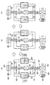
図1の吸着式冷凍機の作動状態を示す概念図である。
第1実施形態の吸着式冷凍機の作動の流れを示すフローチャートである。
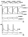
第1実施形態の吸着器を通過する前後の熱媒体温度、吸着器に対する投入熱量および吸着器の冷凍出力を示すグラフである。
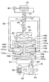
第2実施形態の吸着式冷凍機の概念図である。
図5の吸着式冷凍機の作動状態を示す概念図である。
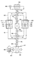
第3実施形態の吸着式冷凍機の概念図である。
図7の吸着式冷凍機の作動状態を示す概念図である。
(第1実施形態)
以下、第1実施形態を図1~図4に基づいて説明する。本第1実施形態では、本開示の吸着式冷凍機を車両空調用吸着式冷凍機に適用している。
以下、第1実施形態を図1~図4に基づいて説明する。本第1実施形態では、本開示の吸着式冷凍機を車両空調用吸着式冷凍機に適用している。
図1に示すように、吸着式冷凍機は2つの吸着器10、20が設けられている。第1吸着器10および第2吸着器20は同一の構成であり、一方の吸着器10、20で被吸着媒体の蒸発と吸着が行われているときに、他方の吸着器10、20で被吸着媒体の脱離と凝縮が行われる。
第1吸着器10には、第1密閉容器11が設けられ、第2吸着器10には、第2密閉容器21が設けられている。これらの密閉容器11、21は気密構造となっており、内部が略真空状態に保たれている。密閉容器11、21の内部には被吸着媒体(冷媒)が封入されている。本第1実施形態では、被吸着媒体として水を用いている。
第1密閉容器11の内部には、第1吸着部12と第1蒸発凝縮部13が設けられ、第2密閉容器21の内部には、第2吸着部22と第2蒸発凝縮部23が設けられている。吸着部12、22および蒸発凝縮部13、23には、熱媒体が流通する配管と、熱媒体と被吸着媒体との熱交換を促進する伝熱部とが設けられており、吸着部12、22では被吸着媒体の吸着および脱離が行われ、蒸発凝縮部13、23では被吸着媒体の蒸発および凝縮が行われる。
吸着部12、22には、被吸着媒体を吸着するための吸着剤が充填されている。吸着剤は、冷却されることで気相状態の被吸着媒体(水蒸気)を吸着し、加熱されることで吸着した被吸着媒体を脱離して気相状態の被吸着媒体(水蒸気)を放出する。吸着剤は、例えばシリカゲルやゼオライトから構成されている。
吸着部12、22には、被吸着媒体の吸着が行われる際に外部から吸着を促進するための熱媒体が供給され、被吸着媒体の脱離が行われる際に外部から脱離を促進するための熱媒体が供給される。また、蒸発凝縮部12、22には、被吸着媒体の蒸発が行われる際に外部から蒸発を促進するための熱媒体が供給され、被吸着媒体の凝縮が行われる際に外部から凝縮を促進するための熱媒体が供給される。
吸着部12、22には、車両走行用のエンジン30から第1熱媒体流路60を介してエンジン冷却用の熱媒体が循環するようになっている。エンジン30は水冷式内燃機関であり、エンジン冷却用の熱媒体として、水にエチレングリコール系の不凍液を混合した流体(エンジン冷却水)を用いている。
蒸発凝縮部13、23には、車両用空調装置40から第2熱媒体流路61を介して空調用の熱媒体が供給される。車両用空調装置40は、車室内に吹き出す空気の通路を構成する空調ケース41が設けられている。空調ケース41の内部には、空気流れ上流側に送風機42が設けられ、空気流れ下流側に室内熱交換器43が設けられている。
室内熱交換器43は、蒸発凝縮部13、23で被吸着媒体の蒸発潜熱によって冷却された熱媒体から冷凍能力を得て、空調ケース41内を流通する空気を冷却するようになっている。なお、本第1実施形態では、空調用の熱媒体としてエンジン冷却用の熱媒体と同一の流体、すなわち水にエチレングリコール系の不凍液を混合した流体を用いている。
吸着部12、22から流出した熱媒体は、第1熱媒体流路60を介して室外熱交換器50に流入可能となっており、蒸発凝縮部13、23から流出した熱媒体は、第2熱媒体流路61を介して室外熱交換器50に流入可能となっている。室外熱交換器50は、熱媒体と室外空気とを熱交換して熱媒体を冷却する放熱器として機能する。室外熱交換器50にて冷却された熱媒体は、吸着部12、22および蒸発凝縮部13、23に供給される。
第1熱媒体流路60には、熱媒体流路を切り替えるための第1切替弁70~第4切替弁73が設けられており、第2熱媒体流路61には、熱媒体流路を切り替えるための第5切替弁74、第6切替弁75が設けられている。
第1切替弁70は、エンジン30の流出側と第1吸着部12の流入側を連通させ、室外熱交換器50の流出側と第2吸着部22の流入側を連通させる状態と、エンジン30の流出側と第2吸着部22の流入側を連通させ、室外熱交換器50の流出側と第1吸着部12の流入側を連通させる状態とを切り替えることができる。第2切替弁71は、第1吸着部12の流出側とエンジン30の流入側を連通させ、第2吸着部22の流出側と室外熱交換器50の流入側を連通させる状態と、第1吸着部12の流出側と室外熱交換器50の流入側を連通させ、第2吸着部22の流出側とエンジン30の流入側を連通させる状態とを切り替えることができる。
第3切替弁72は、エンジン30の流出側と第1切替弁70を連通させ、エンジン30の流入側と第2切替弁71を連通させる状態と、エンジン30の流出側と流入側を連通させ、第1切替弁70と第2切替弁71を連通させる状態とを切り替えることができる。第4切替弁73は、室外熱交換器50の流出側と第1切替弁70を連通させ、室外熱交換器50の流入側と第2切替弁71を連通させる状態と、室外熱交換器50の流出側と流入側を連通させ、第1切替弁70と第2切替弁71を連通させる状態とを切り替えることができる。
第5切替弁74は、第1蒸発凝縮部13の流出側と室外熱交換器50の流入側とを連通させ、第2蒸発凝縮部23の流出側と室内熱交換器43の流入側を連通させる状態と、第1蒸発凝縮部13の流出側と室内熱交換器43の流入側とを連通させ、第2蒸発凝縮部23の流出側と室外熱交換器50の流入側を連通させる状態を切り替えることができる。第6切替弁75は、室外熱交換器50の流出側と第1蒸発凝縮部13の流入側を連通させ、室内熱交換器43の流出側と第2蒸発凝縮部23の流入側とを連通させる状態と、室外熱交換器50の流出側と第2蒸発凝縮部23の流入側を連通させ、室内熱交換器43の流出側と第1蒸発凝縮部13の流入側とを連通させる状態を切り替えることができる。
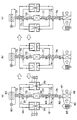
これらの切替弁70~75で熱媒体流路を切り替えることで、図2に示す3つの作動状態を切り替えることができる。
図2(a)に示す第1作動状態では、第1熱媒体流路60に、熱媒体がエンジン30と第1吸着部12を循環する熱媒体回路と、熱媒体が室外熱交換器50と第2吸着部22を循環する熱媒体回路が形成される。また、第2熱媒体流路61に、熱媒体が室外熱交換器50と第1蒸発凝縮部13を循環する熱媒体回路と、熱媒体が室内熱交換器43と第2蒸発凝縮部23を循環する熱媒体回路が形成される。
図2(b)に示す第2作動状態では、第1熱媒体流路60に、熱媒体がエンジン30のみを循環する熱媒体回路と、熱媒体が第1吸着部12と第2吸着部22を循環する熱媒体回路と、熱媒体が室外熱交換器50のみを循環する熱媒体回路が形成される。また、第2熱媒体流路61には、第1作動状態と同一の熱媒体回路が形成される。
図2(c)に示す第3作動状態では、第1熱媒体流路60に、熱媒体がエンジン30と第2吸着部22を循環する熱媒体回路と、熱媒体が室外熱交換器50と第1吸着部12を循環する熱媒体回路が形成される。また、第2熱媒体流路61に、熱媒体が室外熱交換器50と第2蒸発凝縮部23を循環する熱媒体回路と、熱媒体が室内熱交換器43と第1蒸発凝縮部13を循環する熱媒体回路が形成される。
これらの3つの作動状態は、第1作動状態→第2作動状態→第3作動状態→第2作動状態→第1作動状態の順に切り替わる。これらの作動状態については、後で詳細に説明する。
図1に戻り、第1熱媒体流路60には、熱媒体を循環させるための第1ポンプ80、第2ポンプ81が設けられている。第1ポンプ80は、エンジン30の熱媒体流入側に設けられ、エンジン30から熱媒体を第1吸着部12または第2吸着部22に供給する。第2ポンプ81は、室外熱交換器50の熱媒体流入側に設けられ、室外熱交換器50から熱媒体を第1吸着部12または第2吸着部22に供給する。
本第1実施形態では、第2ポンプ81は、第1熱媒体流路60における第3切替弁72と第4切替弁73の間に設けられている。つまり、第2ポンプ81は、上述した第2作動状態における熱媒体が第1吸着部12と第2吸着部22を循環する熱媒体回路内に位置するように設けられている。第2ポンプ81が設けられる位置として「第2切換弁71と第4切換弁73の間」もしくは「第1切替弁70と第4切替弁73の間」を採用してもよい。この位置に設けてもよい理由として、第1吸着部12、第2吸着部22において被吸着媒体が吸着される際の冷熱源である室外熱交換器50を通過した熱媒体が通過する回路上に配されるため、第2ポンプ81を通過する熱交換媒体が徒に昇温してしまうことを抑制することができるためである。
第2熱媒体流路61には、熱媒体を循環させるための第3ポンプ82、第4ポンプ83が設けられている。第3ポンプ82は、室外熱交換器50の熱媒体流入側に設けられ、室外熱交換器50から熱媒体を第1蒸発凝縮部13または第2蒸発凝縮部23に供給する。第4ポンプ83は、室内熱交換器43の熱媒体流入側に設けられ、室内熱交換器43から熱媒体を第1蒸発凝縮部13または第2蒸発凝縮部23に供給する。
吸着式冷凍機には、図示しない電子制御装置が設けられている。電子制御装置は、CPU、ROM及びRAM等を含む周知のマイクロコンピュータとその周辺回路から構成されており、送風機42、切替弁70~75およびポンプ80~83の作動を制御する。
次に、上記構成を備える吸着式冷凍機の作動を図3のフローチャートに基づいて説明する。
まず、吸着式冷凍機を第1作動状態(図2(a))で運転させる(S10)。第1作動状態では、第1吸着部12にエンジン30を冷却した後の熱媒体(加熱媒体)が流入し、第2吸着部22に室外熱交換器50で外気と熱交換した後の熱媒体(冷却媒体)が流入する。また、第1蒸発凝縮部13に室外熱交換器50で外気と熱交換した後の熱媒体が流入し、第2蒸発凝縮部23に室内熱交換器43で空調風を冷却した後の熱媒体が流入する。
第1吸着部12では、エンジン30から供給される熱媒体によって、吸着剤に吸着されている被吸着媒体の脱離が促進される。第1蒸発凝縮部13では、室外熱交換器50から流入する熱媒体によって、第1吸着部12から脱離した気相の被吸着媒体の凝縮が促進される。
第2蒸発凝縮部23では、室内熱交換器43から供給される熱媒体の熱によって、被吸着媒体の蒸発が促進される。被吸着媒体の蒸発潜熱で冷却された熱媒体は室内熱交換器43に流入し、室内に吹き出す空調風が冷却される。第1作動状態では、第2蒸発凝縮部23を通過する前後の熱媒体の温度差が、吸着式冷凍機の冷凍出力となる。
第2吸着部22では、第2蒸発凝縮部23で蒸発した気相の被吸着媒体を吸着し、第2蒸発凝縮部23での被吸着媒体の蒸発が促進される。このとき、第2吸着部22で被吸着媒体の吸着に伴って発生する熱は、室外熱交換器50から流入する熱媒体によって除去される。これにより、第2吸着部22の温度上昇が抑制され、吸着剤の吸着能力低下が抑制される。
以上のように、第1作動状態では、第1吸着器10で、被吸着媒体の脱離および脱離した気相の被吸着媒体の凝縮が行われ、第2吸着器20で、被吸着媒体媒の蒸発および蒸発した気相の被吸着媒体の吸着が行われる。したがって、第1蒸発凝縮部13は気相の被吸着媒体を凝縮させる凝縮器として機能し、第2蒸発凝縮部23は液相の被吸着媒体を蒸発させる蒸発器として機能する。
次に、第1作動状態の終了タイミングか否かを判定する(S11)。第1作動状態が継続すると、第2吸着部22における被吸着媒体の吸着量が増大する。これに伴い、第2吸着部22における被吸着媒体の吸着能力が低下し、吸着式冷凍機の冷凍出力が低下する。このため、本実施形態では、第1作動状態での運転開始から第1所定時間が経過した時点を第1作動状態の終了タイミングとしている。
S11の判定処理の結果、第1作動状態の終了タイミングでないと判定された場合には(S11:NO)、第1作動状態での運転を継続させる(S10)。一方、第1作動状態の終了タイミングであると判定された場合には(S11:YES)、第1切替弁70、第3切替弁72、第4切替弁73を作動させ、吸着式冷凍機を第2作動状態(図2(b))で運転させる(S12)。
第2作動状態では、第1切替弁70~第4切替弁73によって、熱媒体が第1吸着部12と第2吸着部22を循環する熱媒体回路が形成される。この熱媒体回路は、エンジン30および室外熱交換部50と遮断されており、エンジン30からの熱媒体(加熱媒体)および室外熱交換部50からの熱媒体(冷却媒体)の流入が遮断される。これにより、第1吸着部12と第2吸着部22の間で、熱媒体を介して熱交換が行われる。第1作動状態の終了時には第1吸着部12の方が第2吸着部22よりも高温になっているので、第1作動状態から第2作動状態に移行すると、第1吸着部12が温度低下し、第2吸着部22が温度上昇する。
次に、第2作動状態の終了タイミングか否かを判定する(S13)。第2作動状態が継続すると、第1吸着部12と第2吸着部22の温度差が徐々に小さくなり、第1吸着部12と第2吸着部22の間の熱交換効率が低下する。このため、本実施形態では、第2作動状態での運転開始から第2所定時間が経過した時点を第2作動状態の終了タイミングとしている。第2所定時間(第2作動状態が開始してから終了するまでの時間)は、第2作動状態が開始してから第2吸着部22に吸着されている被吸着媒体が脱離し始めるまでの時間以下に設定することができる。
S13の判定処理の結果、第2作動状態の終了タイミングでないと判定された場合には(S13:NO)、第2作動状態での運転を継続させる(S12)。一方、第2作動状態の終了タイミングであると判定された場合には(S13:YES)、第2切替弁71、第3切替弁72、第4切替弁73を作動させ、吸着式冷凍機を第3作動状態で運転させる(S14)。
第3作動状態では、上述した第1作動状態に対して、第1吸着器10と第2吸着器20の作動が入れ替わる。つまり、第1吸着器10では、被吸着媒体の蒸発および蒸発した被吸着媒体の吸着が行われ、第2吸着器20では、被吸着媒体の脱離および脱離した被吸着媒体の冷却凝縮が行われる。したがって、第1蒸発凝縮部13は液相の被吸着媒体を蒸発させる蒸発器として機能し、第2蒸発凝縮部23は気相の被吸着媒体を凝縮させる凝縮器として機能する。
第3作動状態では、第1蒸発凝縮部13で液相の被吸着媒体が蒸発し、被吸着媒体の蒸発潜熱で室内熱交換に43に循環する熱媒体が冷却される。つまり、第3作動状態では、第1蒸発凝縮部13を通過する前後の熱媒体の温度差が、吸着式冷凍機の冷凍出力となる。
次に、第3作動状態の終了タイミングか否かを判定する(S15)。第3作動状態が継続すると、第1吸着部12における被吸着媒体の吸着量が増大する。これに伴い、第1吸着部12における被吸着媒体の吸着能力が低下し、吸着式冷凍機の冷凍出力が低下する。このため、本実施形態では、第3作動状態での運転開始から第3所定時間が経過した時点を第3作動状態の終了タイミングとしている。
S15の判定処理の結果、第3作動状態の終了タイミングでないと判定された場合には(S15:NO)、第3作動状態での運転を継続させる(S14)。一方、第3作動状態の終了タイミングであると判定された場合には(S15:YES)、第1切替弁70、第3切替弁72、第4切替弁73を作動させ、吸着式冷凍機を第2作動状態(図2(b))で運転させる(S16)。
次に、第2作動状態の終了タイミングか否かを判定する(S17)。この結果、第2作動状態の終了タイミングでないと判定された場合には(S17:NO)、第2作動状態での運転を継続させる(S16)。一方、第2作動状態の終了タイミングであると判定された場合には(S17:YES)、第2切替弁71、第3切替弁72、第4切替弁73を作動させ、吸着式冷凍機を第1作動状態で運転させる(S10)。
以後、吸着式冷凍機は、第1作動状態→第2作動状態→第3作動状態→第2作動状態→第1作動状態の順に作動状態を切り替えることで、連続的に冷凍能力を発揮することができる。
図4上段は、吸着部12、22に流入する際の熱媒体温度(入口温度)および吸着部12、22から流出する際の熱媒体温度(出口温度)と、蒸発凝縮部13、23に流入する際の熱媒体温度(入口温度)および蒸発凝縮部13、23から流出する際の熱媒体温度(出口温度)を示している。図4の下段は、吸着器10、20に対する投入熱量と、吸着器10、20の冷凍出力を示している。なお、図4の上段では、第1蒸発凝縮部13と第2蒸発凝縮部23を区別していない。
第1作動状態では、第1吸着部12がエンジン30から供給される熱媒体(加熱媒体)によって昇温され、第1吸着部12の出口温度が第1吸着部12の入口温度に近づく。また、第2吸着部22が室外熱交換器50から供給される熱媒体(冷却媒体)によって冷却され、第2吸着部22の出口温度が第2吸着部22の入口温度に近づく。
第3作動状態では、第2吸着部22がエンジン30から供給される熱媒体(加熱媒体)によって昇温され、第2吸着部22の出口温度が第2吸着部22の入口温度に近づく。また、第1吸着部12が室外熱交換器50から供給される熱媒体(冷却媒体)によって冷却され、第1吸着部12の出口温度が第1吸着部12の入口温度に近づく。
このため、第1作動状態から第3作動状態に直接切り替わると、第1吸着部12と室外熱交換器50から供給される熱媒体(冷却媒体)との温度差が大きくなり、第2吸着部22とエンジン30から供給される熱媒体(加熱媒体)との温度差が大きくなる。また、第3作動状態から第1作動状態に直接切り替わると、第1吸着部12とエンジン30から供給される熱媒体(加熱媒体)との温度差が大きくなり、第2吸着部22と室外熱交換器50から供給される熱媒体(冷却媒体)との温度差が大きくなる。この結果、外部(エンジン30、室外熱交換器50)からの多くの投入熱量が必要となる。
これに対し、本第1実施形態では、第1作動状態から第2作動状態を経て第3作動状態に切り替わり、第3作動状態から第2作動状態を経て第1作動状態に切り替わるようになっている。第2作動状態では、熱媒体が第1吸着部12と第2吸着部22を循環する熱媒体回路が形成され、第1吸着部12と第2吸着部22との間で熱媒体を介して熱交換が行われる。
このため、第1作動状態から第2作動状態に切り替わった場合には、第1吸着部12を温度低下させ、第2吸着部22を温度上昇させることができる。また、第3作動状態から第2作動状態に切り替わった場合には、第1吸着部12を温度上昇させ、第2吸着部22を温度低下させることができる。
図4の下段に示す投入熱量に付された斜線部分は、第2作動状態において第1吸着部12と第2吸着部22との間で熱交換された熱量を示している。つまり、第2作動状態で第1吸着部12と第2吸着部22との間で熱交換させることで、斜線部分に対応する熱量分だけ、外部からの投入熱量を低減することができる。
以上説明した本第1実施形態によれば、2つの吸着部12、22に供給される冷却媒体と加熱媒体を切り替える際に、これらの吸着部12、22の間で熱交換させる第2作動状態を設けることで、吸着部12、22と冷却媒体または加熱媒体との温度差を小さくすることができる。これにより、外部からの投入熱量を低減することができ、吸着式冷凍機のCOP(=冷凍出力/外部からの投入熱量)を向上させることができる。また、エンジン30が発生する熱量や室外熱交換器50の体格に制約があるような場合であっても、吸着式冷凍機を連続的に運転させ、冷凍能力を発揮させることができる。
また、第2作動状態が継続すると、2つの吸着部12、22の温度差が小さくなり、吸着部12、22間の熱交換効率が低下する。このため、本第1実施形態では、第2作動状態の実行時間を第2作動状態が開始してから吸着部12、22に吸着されている被吸着媒体が脱離し始めるまでの時間以下に設定している。これにより、第2作動状態にて第1吸着部12と第2吸着部22の熱交換効率が所定値に低下するまで吸着部12、22同士で熱交換させ、その後は第1作動状態または第3作動状態に切り替えることで、吸着式冷凍機の効率を向上させることができる。
また、本第1実施形態では、第2作動状態で熱媒体が第1吸着部12と第2吸着部22を循環する熱媒体回路内に第2ポンプ81を設けている。これにより、エンジン30および室外熱交換器50と遮断した状態で、第1吸着部12と第2吸着部22との間で熱媒体を循環させることができる。
(第2実施形態)
次に、第2実施形態を図5、図6に基づいて説明する。上記第1実施形態と同様の部分については説明を省略し、異なる部分についてのみ説明する。
(第2実施形態)
次に、第2実施形態を図5、図6に基づいて説明する。上記第1実施形態と同様の部分については説明を省略し、異なる部分についてのみ説明する。
本第2実施形態では、上記第1実施形態に対して、吸着式冷凍機に凝縮専用の凝縮部102および蒸発専用の蒸発部105が設けられている点が異なっている。
図5に示すように、本第2実施形態の吸着式冷凍機は、1つの吸着器100が設けられている。吸着器100には密閉容器101が設けられており、密閉容器101には4つの室101a~101dが設けられている。
上方から第1室101a、第2室101bおよび第3室101c、第4室101dの順に配置されている。第1室101aと第4室101dは、第2室101bまたは第3室101cを介して連通可能となっている。また、第1室101aと第4室101dは連通路101eによって直接連通している。
第1室101aには凝縮部102が収納されており、第2室101bには第1吸着部103が収納されており、第3室101cには第2吸着部104が収納されており、第4室101dには蒸発部105が収納されている。
隣接する室101a~101dの間には、互いを連通または遮断するための開閉弁106~109が設けられている。第1室101aと第2室101bとの間には第1開閉弁106が設けられ、第1室101aと第3室101cとの間には第2開閉弁107が設けられ、第2室101bと第4室101dとの間には第3開閉弁108が設けられ、第3室101cと第4室101dとの間には第4開閉弁109が設けられている。これらの開閉弁106~109は、各室101a~101dの圧力差によって開閉するようになっている。
本第2実施形態では、室外熱交換器50から流出する熱媒体は、凝縮部102のみに供給され、室内熱交換器43から流出する熱媒体は、蒸発部105のみに供給される。このため、凝縮部102では被吸着媒体の凝縮のみが行われ、蒸発部105では被吸着媒体の蒸発のみが行われる。
次に、本第2実施形態の吸着式冷凍機の作動を図6に基づいて説明する。各作動状態の切り替え条件は、上記第1実施形態と同様である。
図6(a)に示す第1作動状態では、エンジン30から熱媒体(加熱媒体)が第1吸着部103に流入し、室外熱交換器50から熱媒体(冷却媒体)が第2吸着部104に流入する。また、室外熱交換器50から熱媒体が凝縮部102に流入し、室内熱交換器43から熱媒体が凝縮部105に流入する。
蒸発部105では、液相の被吸着媒体が室内熱交換器43から供給される熱媒体の熱によって蒸発し、第4開閉弁109が開放する。被吸着媒体の蒸発潜熱で冷却された熱媒体は室内熱交換器43に流入し、室内に吹き出す空調風が冷却される。第2吸着部104では、蒸発部105で蒸発した気相の被吸着媒体を吸着する。第2吸着部22は、室外熱交換器50から供給される熱媒体によって、被吸着媒体の吸着に伴う温度上昇が抑制される。
第1吸着部104では、被吸着媒体がエンジン30から供給される熱媒体によって脱離し、第1開閉弁106が開放する。凝縮部102では、第1吸着部104から脱離した気相の被吸着媒体が室外熱交換器50から供給される熱媒体によって冷却されて凝縮する。凝縮部102で凝縮した被吸着媒体は、連通路101eを介して蒸発部105に移動する。
図6(b)に示す第2作動状態では、第1切替弁70~第4切替弁73によって、エンジン30および室外熱交換部50と遮断した状態で、熱媒体が第1吸着部103と第2吸着部104を循環する熱媒体回路が形成される。これにより、第1吸着部103と第2吸着部104との間で熱媒体を介して熱交換が行われる。
図6(c)に示す第3作動状態では、上述した第1作動状態に対して、凝縮部102および蒸発部105の作動は同一であり、第1吸着部103と第2吸着部104の作動が入れ替わる。つまり、蒸発部105で蒸発した被吸着媒体が第1吸着部103で吸着され、第2吸着部104で脱離した被吸着媒体は凝縮部102で凝縮される。
以上説明した本第2実施形態においても、2つの吸着部103、104に冷却媒体と加熱媒体を交互に切り替えて供給する際に、2つの吸着部103、104の間で熱交換させる第2作動状態を設けることで、上記第1実施形態と同様の効果を得ることができる。
また、本第2実施形態では、凝縮専用の凝縮部102と蒸発専用の蒸発部105を用いているので、凝縮部102および蒸発部105で供給される熱媒体を切り替る必要がない。この結果、吸着式冷凍機の効率を向上させることができる。
(第3実施形態)
次に、第3実施形態を図7、図8に基づいて説明する。上記第1実施形態と同様の部分については説明を省略し、異なる部分についてのみ説明する。
(第3実施形態)
次に、第3実施形態を図7、図8に基づいて説明する。上記第1実施形態と同様の部分については説明を省略し、異なる部分についてのみ説明する。
本第3実施形態では、上記第1実施形態に対して、第2作動状態で第2熱媒体流路61に形成される熱媒体回路が異なっている。
図7に示すように、本第3実施形態の第2熱媒体流路61には、第7切替弁76、第8切替弁77が設けられている。第7切替弁76は、室内熱交換器43の流出側と第6切替弁75を連通させ、室内熱交換器43の流入側と第5切替弁74を連通させる状態と、室内熱交換器43の流出側と流入側を連通させ、第5切替弁74と第6切替弁75を連通させる状態とを切り替えることができる。第8切替弁77は、室外熱交換器50の流出側と第6切替弁75を連通させ、室外熱交換器50の流入側と第5切替弁74を連通させる状態と、室外熱交換器50の流出側と流入側を連通させ、第5切替弁74と第6切替弁75を連通させる状態とを切り替えることができる。
図8(a)に示す第1作動状態と図8(c)に示す第3作動状態では、第1熱媒体流路60および第2熱媒体流路61に上記第1実施形態と同様の熱媒体回路が形成される。また、図8(b)に示す第2作動状態では、第1熱媒体流路60に上記第1実施形態と同様の熱媒体回路が形成される。
図8(b)に示すように、第2作動状態では、第2熱媒体流路61に、熱媒体が室内熱交換器43のみを循環する熱媒体回路と、熱媒体が第1蒸発凝縮部13と第2蒸発凝縮部23を循環する熱媒体回路(第2の熱媒体回路)と、熱媒体が室外熱交換器50のみを循環する熱媒体回路が形成される。このため、第2作動状態では、第1蒸発凝縮部13と第2蒸発凝縮部23との間で熱媒体を介して熱交換が行われる。
以上説明した本第3実施形態によれば、上記第1実施形態の効果に加え、2つの蒸発凝縮部13、23に室内熱交換器43からの熱媒体と室外熱交換器50からの熱媒体を交互に切り替えて供給する際に、これらの蒸発凝縮部13、23の間で熱交換させる第2作動状態を設けることで、外部からの投入熱量を低減することができる。これにより、吸着式冷凍機のCOP(=冷凍出力/外部からの投入熱量)を向上させることができる。
以上、実施形態について説明したが、本開示はこれに限定されるものではなく、本開示の範囲を逸脱しない限り、各実施形態の記載文言に限定されず、当業者がそれらから容易に置き換えられる範囲にも及び、かつ、当業者が通常有する知識に基づく改良を適宜付加することができる。上記実施形態の変形例について述べる。
例えば、上記各実施形態では、第1切替弁70および第2切替弁71を個別の切替弁として構成したが、これに限らず、これらは1つの切替弁によって構成してもよい。
また、上記各実施形態では、本開示を車両用空調装置用吸着式冷凍機に適用したが、これに限らず、家庭用や業務用等の吸着式冷凍機に適用してもよい。
本開示は、実施例に準拠して記述されたが、本開示は当該実施例や構造に限定されるものではないと理解される。本開示は、様々な変形例や均等範囲内の変形をも包含する。加えて、様々な組み合わせや形態、さらには、それらに一要素のみ、それ以上、あるいはそれ以下、を含む他の組み合わせや形態をも、本開示の範疇や思想範囲に入るものである。
Claims (4)
- 被吸着媒体の蒸発および吸着と、被吸着媒体の脱離および凝縮とを行い、被吸着媒体の蒸発潜熱により冷凍能力を得る吸着式冷凍機であって、
被吸着媒体を吸着する際に外部から吸着を促進するための熱媒体が供給され、被吸着媒体を脱離する際に外部から脱離を促進するための熱媒体が供給される第1、第2吸着部(12、22、103、104)と、
前記第1、第2吸着部(12、22、103、104)に供給される熱媒体の流路を切り替える流路切替部(70~73)とを備え、
前記流路切替部(70~73)は、
前記第1吸着部(12、103)に外部から被吸着媒体の吸着を促進するための熱媒体が供給され、前記第2吸着部(22、104)に外部から被吸着媒体の脱離を促進するための熱媒体が供給される第1作動状態と、外部からの熱媒体の供給が遮断された状態で、前記第1吸着部(12、103)と前記第2吸着部(22、104)との間で熱媒体を循環させる熱媒体循環回路を形成する第2作動状態と、前記第1吸着部(12、103)に外部から被吸着媒体の脱離を促進するための熱媒体が供給され、前記第2吸着部(22、104)に外部から被吸着媒体の吸着を促進するための熱媒体が供給される第3作動状態とを切り替えることができ、
前記第1作動状態から前記第2作動状態を経て前記第3作動状態に切り替え、前記第3作動状態から前記第2作動状態を経て前記第1作動状態に切り替えることを特徴とする吸着式冷凍機。 - 前記第2作動状態の実行時間は、前記第2作動状態が開始してから前記第1吸着部(12、103)または前記第2吸着部(22、104)に吸着されていた被吸着媒体が脱離し始めるまでの時間以下に設定されていることを特徴とする請求項1に記載の吸着式冷凍機。
- 前記第2作動状態で形成される前記熱媒体循環回路内に、熱媒体を循環させるための熱媒体循環部(81)が設けられていることを特徴とする請求項1または2に記載の吸着式冷凍機。
- 前記吸着部(12、22)から脱離した被吸着媒体を凝縮する際に外部から凝縮を促進するための熱媒体が供給され、前記吸着部(12、22)に吸着させる被吸着媒体を蒸発する際に外部から蒸発を促進するための熱媒体が供給される第1、第2蒸発凝縮部(13、23)を備え、
前記第1作動状態では、前記第1蒸発凝縮部(13)に外部から被吸着媒体の凝縮を促進するための熱媒体が供給され、前記第2蒸発凝縮部(23)に外部から被吸着媒体の蒸発を促進するための熱媒体が供給され、
前記第2作動状態では、外部からの熱媒体の供給が遮断された状態で、前記第1蒸発凝縮部(13)と前記第2蒸発凝縮部(23)との間で熱媒体を循環させる第2の熱媒体循環回路が形成され、
前記第3作動状態では、前記第1蒸発凝縮部(13)に外部から被吸着媒体の蒸発を促進するための熱媒体が供給され、前記第2蒸発凝縮部(23)に外部から被吸着媒体の凝縮を促進するための熱媒体が供給されることを特徴とする請求項1ないし3のいずれか1つに記載の吸着式冷凍機。
Priority Applications (2)
| Application Number | Priority Date | Filing Date | Title |
|---|---|---|---|
| DE112016001717.0T DE112016001717B4 (de) | 2015-04-13 | 2016-04-12 | Adsorptionskühlanlage |
| CN201680021357.5A CN107429955B (zh) | 2015-04-13 | 2016-04-12 | 吸附式制冷机 |
Applications Claiming Priority (2)
| Application Number | Priority Date | Filing Date | Title |
|---|---|---|---|
| JP2015081411A JP6260576B2 (ja) | 2015-04-13 | 2015-04-13 | 吸着式冷凍機 |
| JP2015-081411 | 2015-04-13 |
Publications (1)
| Publication Number | Publication Date |
|---|---|
| WO2016166966A1 true WO2016166966A1 (ja) | 2016-10-20 |
Family
ID=57125919
Family Applications (1)
| Application Number | Title | Priority Date | Filing Date |
|---|---|---|---|
| PCT/JP2016/001980 Ceased WO2016166966A1 (ja) | 2015-04-13 | 2016-04-12 | 吸着式冷凍機 |
Country Status (4)
| Country | Link |
|---|---|
| JP (1) | JP6260576B2 (ja) |
| CN (1) | CN107429955B (ja) |
| DE (1) | DE112016001717B4 (ja) |
| WO (1) | WO2016166966A1 (ja) |
Families Citing this family (5)
| Publication number | Priority date | Publication date | Assignee | Title |
|---|---|---|---|---|
| JP7015178B2 (ja) * | 2018-01-19 | 2022-02-02 | 株式会社デンソー | 吸着式冷凍機 |
| JP7015177B2 (ja) * | 2018-01-19 | 2022-02-02 | 株式会社デンソー | 吸着式冷凍機 |
| DE102018204333A1 (de) * | 2018-03-21 | 2019-09-26 | Bayerische Motoren Werke Aktiengesellschaft | Temperierungseinrichtung und Verfahren zum Temperieren wenigstens einer Fahrzeugkomponente eines elektrisch betreibbaren Kraftfahrzeugs sowie Kraftfahrzeug |
| US20220390154A1 (en) * | 2019-11-07 | 2022-12-08 | Sorption Technologies GmbH | Adsorption refrigeration machine or heat pump with a liquid-phase refrigerant distribution function, and method for operating the adsorption refrigeration machine or heat pump |
| CN117968426B (zh) * | 2024-03-14 | 2025-12-26 | 北京理工大学 | 一种热管理系统的热管装置、热管理系统及其使用方法 |
Citations (8)
| Publication number | Priority date | Publication date | Assignee | Title |
|---|---|---|---|---|
| JPS6458966A (en) * | 1987-08-28 | 1989-03-06 | Nishodo Kuchoki Kk | Method of operating adsorption type refrigeration system |
| JPH02230068A (ja) * | 1989-02-28 | 1990-09-12 | Nishiyodo Kuuchiyouki Kk | 吸着式冷凍機とその運転方法 |
| JP2003166770A (ja) * | 2001-11-30 | 2003-06-13 | Denso Corp | 吸着式冷凍機 |
| JP2003240383A (ja) * | 2002-02-08 | 2003-08-27 | Denso Corp | 吸着式冷凍装置 |
| JP2005326073A (ja) * | 2004-05-13 | 2005-11-24 | Denso Corp | 冷凍装置 |
| JP2007040592A (ja) * | 2005-08-02 | 2007-02-15 | Denso Corp | 吸着器 |
| JP2012506817A (ja) * | 2008-10-30 | 2012-03-22 | エアバス オペレーションズ ゲーエムベーハー | 航空機の改良された吸着冷却システム及び吸着冷却方法 |
| JP2014513789A (ja) * | 2011-05-19 | 2014-06-05 | ゾルテッヒ アーゲー | 循環的に作動する熱吸着式加熱または冷却システムを動作させるための方法 |
Family Cites Families (5)
| Publication number | Priority date | Publication date | Assignee | Title |
|---|---|---|---|---|
| JP3831963B2 (ja) | 1996-01-12 | 2006-10-11 | 株式会社デンソー | 吸着式冷凍装置 |
| JP4096646B2 (ja) * | 2002-07-09 | 2008-06-04 | 株式会社デンソー | 冷却システム |
| JP6015137B2 (ja) * | 2012-05-31 | 2016-10-26 | アイシン精機株式会社 | 吸収式ヒートポンプ装置 |
| JP2015048986A (ja) * | 2013-09-02 | 2015-03-16 | 富士通株式会社 | 空気調和装置 |
| JP2015081411A (ja) | 2013-10-21 | 2015-04-27 | 住友林業株式会社 | 建物の採光構造 |
-
2015
- 2015-04-13 JP JP2015081411A patent/JP6260576B2/ja not_active Expired - Fee Related
-
2016
- 2016-04-12 WO PCT/JP2016/001980 patent/WO2016166966A1/ja not_active Ceased
- 2016-04-12 DE DE112016001717.0T patent/DE112016001717B4/de not_active Expired - Fee Related
- 2016-04-12 CN CN201680021357.5A patent/CN107429955B/zh not_active Expired - Fee Related
Patent Citations (8)
| Publication number | Priority date | Publication date | Assignee | Title |
|---|---|---|---|---|
| JPS6458966A (en) * | 1987-08-28 | 1989-03-06 | Nishodo Kuchoki Kk | Method of operating adsorption type refrigeration system |
| JPH02230068A (ja) * | 1989-02-28 | 1990-09-12 | Nishiyodo Kuuchiyouki Kk | 吸着式冷凍機とその運転方法 |
| JP2003166770A (ja) * | 2001-11-30 | 2003-06-13 | Denso Corp | 吸着式冷凍機 |
| JP2003240383A (ja) * | 2002-02-08 | 2003-08-27 | Denso Corp | 吸着式冷凍装置 |
| JP2005326073A (ja) * | 2004-05-13 | 2005-11-24 | Denso Corp | 冷凍装置 |
| JP2007040592A (ja) * | 2005-08-02 | 2007-02-15 | Denso Corp | 吸着器 |
| JP2012506817A (ja) * | 2008-10-30 | 2012-03-22 | エアバス オペレーションズ ゲーエムベーハー | 航空機の改良された吸着冷却システム及び吸着冷却方法 |
| JP2014513789A (ja) * | 2011-05-19 | 2014-06-05 | ゾルテッヒ アーゲー | 循環的に作動する熱吸着式加熱または冷却システムを動作させるための方法 |
Also Published As
| Publication number | Publication date |
|---|---|
| DE112016001717T5 (de) | 2017-12-28 |
| DE112016001717B4 (de) | 2022-10-06 |
| CN107429955B (zh) | 2020-06-16 |
| JP6260576B2 (ja) | 2018-01-17 |
| JP2016200342A (ja) | 2016-12-01 |
| CN107429955A (zh) | 2017-12-01 |
Similar Documents
| Publication | Publication Date | Title |
|---|---|---|
| JP4192385B2 (ja) | 吸着式冷凍機 | |
| JP6260576B2 (ja) | 吸着式冷凍機 | |
| CN204774485U (zh) | 车辆空调系统、空调系统 | |
| WO2011142352A1 (ja) | 車両用空調装置 | |
| JP2016080310A (ja) | 冷却システム | |
| JP5402564B2 (ja) | 吸着式冷凍機および冷凍装置 | |
| JP6292211B2 (ja) | 車両用吸着式空調装置 | |
| JP3959829B2 (ja) | 冷凍装置および空調装置 | |
| JP4082378B2 (ja) | 冷凍装置 | |
| JP4363336B2 (ja) | 冷暖房装置 | |
| JP2014001876A (ja) | 吸着式冷凍装置及びエンジン駆動式空調装置 | |
| JPH1163719A (ja) | 冷凍装置 | |
| JP7015178B2 (ja) | 吸着式冷凍機 | |
| KR102097783B1 (ko) | 흡착식 차량용 공조장치 | |
| JP7684553B2 (ja) | 自動車用冷凍サイクル装置 | |
| JP2004237816A (ja) | 車両用吸着式空調装置 | |
| JP4086011B2 (ja) | 冷凍装置 | |
| JP7015177B2 (ja) | 吸着式冷凍機 | |
| JP2017166429A (ja) | 排熱回収システム | |
| JP6632423B2 (ja) | 冷凍サイクル、およびこの冷凍サイクルを用いた車両用の空調システム | |
| JPH11142015A (ja) | エンジン駆動式冷凍装置 | |
| JP2016050715A (ja) | 吸着式冷凍機を備える空調システム | |
| CN112393403A (zh) | 用于双制冷式空调的控制方法、控制装置及双制冷式空调 | |
| JP2019026140A (ja) | 車両用空調システム | |
| JP2019168113A (ja) | 吸着蓄熱システムを利用した車両用空調装置 |
Legal Events
| Date | Code | Title | Description |
|---|---|---|---|
| 121 | Ep: the epo has been informed by wipo that ep was designated in this application |
Ref document number: 16779762 Country of ref document: EP Kind code of ref document: A1 |
|
| WWE | Wipo information: entry into national phase |
Ref document number: 112016001717 Country of ref document: DE |
|
| 122 | Ep: pct application non-entry in european phase |
Ref document number: 16779762 Country of ref document: EP Kind code of ref document: A1 |