WO2016166868A1 - 投射型映像表示装置および投射型映像表示装置における情報表示方法 - Google Patents
投射型映像表示装置および投射型映像表示装置における情報表示方法 Download PDFInfo
- Publication number
- WO2016166868A1 WO2016166868A1 PCT/JP2015/061731 JP2015061731W WO2016166868A1 WO 2016166868 A1 WO2016166868 A1 WO 2016166868A1 JP 2015061731 W JP2015061731 W JP 2015061731W WO 2016166868 A1 WO2016166868 A1 WO 2016166868A1
- Authority
- WO
- WIPO (PCT)
- Prior art keywords
- display
- display device
- projection
- information
- power supply
- Prior art date
- Legal status (The legal status is an assumption and is not a legal conclusion. Google has not performed a legal analysis and makes no representation as to the accuracy of the status listed.)
- Ceased
Links
Images








Classifications
-
- G—PHYSICS
- G03—PHOTOGRAPHY; CINEMATOGRAPHY; ANALOGOUS TECHNIQUES USING WAVES OTHER THAN OPTICAL WAVES; ELECTROGRAPHY; HOLOGRAPHY
- G03B—APPARATUS OR ARRANGEMENTS FOR TAKING PHOTOGRAPHS OR FOR PROJECTING OR VIEWING THEM; APPARATUS OR ARRANGEMENTS EMPLOYING ANALOGOUS TECHNIQUES USING WAVES OTHER THAN OPTICAL WAVES; ACCESSORIES THEREFOR
- G03B21/00—Projectors or projection-type viewers; Accessories therefor
- G03B21/14—Details
- G03B21/20—Lamp housings
- G03B21/2086—Security or safety means in lamp houses
-
- G—PHYSICS
- G03—PHOTOGRAPHY; CINEMATOGRAPHY; ANALOGOUS TECHNIQUES USING WAVES OTHER THAN OPTICAL WAVES; ELECTROGRAPHY; HOLOGRAPHY
- G03B—APPARATUS OR ARRANGEMENTS FOR TAKING PHOTOGRAPHS OR FOR PROJECTING OR VIEWING THEM; APPARATUS OR ARRANGEMENTS EMPLOYING ANALOGOUS TECHNIQUES USING WAVES OTHER THAN OPTICAL WAVES; ACCESSORIES THEREFOR
- G03B21/00—Projectors or projection-type viewers; Accessories therefor
-
- G—PHYSICS
- G03—PHOTOGRAPHY; CINEMATOGRAPHY; ANALOGOUS TECHNIQUES USING WAVES OTHER THAN OPTICAL WAVES; ELECTROGRAPHY; HOLOGRAPHY
- G03B—APPARATUS OR ARRANGEMENTS FOR TAKING PHOTOGRAPHS OR FOR PROJECTING OR VIEWING THEM; APPARATUS OR ARRANGEMENTS EMPLOYING ANALOGOUS TECHNIQUES USING WAVES OTHER THAN OPTICAL WAVES; ACCESSORIES THEREFOR
- G03B21/00—Projectors or projection-type viewers; Accessories therefor
- G03B21/14—Details
-
- G—PHYSICS
- G03—PHOTOGRAPHY; CINEMATOGRAPHY; ANALOGOUS TECHNIQUES USING WAVES OTHER THAN OPTICAL WAVES; ELECTROGRAPHY; HOLOGRAPHY
- G03B—APPARATUS OR ARRANGEMENTS FOR TAKING PHOTOGRAPHS OR FOR PROJECTING OR VIEWING THEM; APPARATUS OR ARRANGEMENTS EMPLOYING ANALOGOUS TECHNIQUES USING WAVES OTHER THAN OPTICAL WAVES; ACCESSORIES THEREFOR
- G03B21/00—Projectors or projection-type viewers; Accessories therefor
- G03B21/14—Details
- G03B21/16—Cooling; Preventing overheating
-
- G—PHYSICS
- G03—PHOTOGRAPHY; CINEMATOGRAPHY; ANALOGOUS TECHNIQUES USING WAVES OTHER THAN OPTICAL WAVES; ELECTROGRAPHY; HOLOGRAPHY
- G03B—APPARATUS OR ARRANGEMENTS FOR TAKING PHOTOGRAPHS OR FOR PROJECTING OR VIEWING THEM; APPARATUS OR ARRANGEMENTS EMPLOYING ANALOGOUS TECHNIQUES USING WAVES OTHER THAN OPTICAL WAVES; ACCESSORIES THEREFOR
- G03B21/00—Projectors or projection-type viewers; Accessories therefor
- G03B21/14—Details
- G03B21/20—Lamp housings
- G03B21/2006—Lamp housings characterised by the light source
- G03B21/2033—LED or laser light sources
-
- H—ELECTRICITY
- H04—ELECTRIC COMMUNICATION TECHNIQUE
- H04N—PICTORIAL COMMUNICATION, e.g. TELEVISION
- H04N5/00—Details of television systems
- H04N5/63—Generation or supply of power specially adapted for television receivers
-
- H—ELECTRICITY
- H04—ELECTRIC COMMUNICATION TECHNIQUE
- H04N—PICTORIAL COMMUNICATION, e.g. TELEVISION
- H04N9/00—Details of colour television systems
- H04N9/12—Picture reproducers
- H04N9/31—Projection devices for colour picture display, e.g. using electronic spatial light modulators [ESLM]
- H04N9/3141—Constructional details thereof
-
- H—ELECTRICITY
- H04—ELECTRIC COMMUNICATION TECHNIQUE
- H04N—PICTORIAL COMMUNICATION, e.g. TELEVISION
- H04N9/00—Details of colour television systems
- H04N9/12—Picture reproducers
- H04N9/31—Projection devices for colour picture display, e.g. using electronic spatial light modulators [ESLM]
- H04N9/3141—Constructional details thereof
- H04N9/315—Modulator illumination systems
- H04N9/3155—Modulator illumination systems for controlling the light source
-
- G—PHYSICS
- G03—PHOTOGRAPHY; CINEMATOGRAPHY; ANALOGOUS TECHNIQUES USING WAVES OTHER THAN OPTICAL WAVES; ELECTROGRAPHY; HOLOGRAPHY
- G03B—APPARATUS OR ARRANGEMENTS FOR TAKING PHOTOGRAPHS OR FOR PROJECTING OR VIEWING THEM; APPARATUS OR ARRANGEMENTS EMPLOYING ANALOGOUS TECHNIQUES USING WAVES OTHER THAN OPTICAL WAVES; ACCESSORIES THEREFOR
- G03B21/00—Projectors or projection-type viewers; Accessories therefor
- G03B21/005—Projectors using an electronic spatial light modulator but not peculiar thereto
- G03B21/006—Projectors using an electronic spatial light modulator but not peculiar thereto using LCD's
-
- G—PHYSICS
- G03—PHOTOGRAPHY; CINEMATOGRAPHY; ANALOGOUS TECHNIQUES USING WAVES OTHER THAN OPTICAL WAVES; ELECTROGRAPHY; HOLOGRAPHY
- G03B—APPARATUS OR ARRANGEMENTS FOR TAKING PHOTOGRAPHS OR FOR PROJECTING OR VIEWING THEM; APPARATUS OR ARRANGEMENTS EMPLOYING ANALOGOUS TECHNIQUES USING WAVES OTHER THAN OPTICAL WAVES; ACCESSORIES THEREFOR
- G03B21/00—Projectors or projection-type viewers; Accessories therefor
- G03B21/005—Projectors using an electronic spatial light modulator but not peculiar thereto
- G03B21/008—Projectors using an electronic spatial light modulator but not peculiar thereto using micromirror devices
Definitions
- the present invention relates to a technology of a projection type video display device, and more particularly to a projection type video display device having a sub display for displaying information and a technology effective when applied to an information display method in the projection type video display device. .
- a projection-type video display device such as a liquid crystal projector
- various information such as the image information being projected and the state of the device are displayed on the back side of the device.
- Patent Document 1 Japanese Patent Application Laid-Open No. 2005-221898
- Patent Document 1 has a sub-screen provided on the opposite side of the projection lens of the projector device, displays input image information, or inputs input image information.
- the image information is displayed and the message transmitted from the terminal device is displayed superimposed on the image information.
- Patent Document 2 a liquid crystal or the like installed near the driver's seat and displaying a route guidance screen, a television screen, or the like.
- a car navigation device having a main display and a sub display installed near the back seat and displaying a route guidance screen, a screen of a television, a game, etc. is described, and so-called electronic paper may be used for the sub display It is described.
- Patent Document 3 uses a display using a reflective liquid crystal having a memory property as a sub-display of a personal computer, fixed information that does not need to be frequently rewritten, and a main display of a personal computer. It is described that an inactive window, an image for viewing, and the like are displayed on a sub-display to effectively utilize the area of the main display and improve the efficiency of editing and the like.
- the sub-display is provided in the projector main body and various information is displayed as described in Patent Document 1, for example, an apparatus including an error or the like regardless of whether or not an image is being projected on the screen.
- various information such as the status of the projector and identification information of the projector main body, the user can refer to them.
- the sub-display is configured by a normal liquid crystal display, even if various kinds of information as described above are displayed, the display on the sub-display disappears when the power supply to the projector is stopped.
- the person in charge of maintenance service needs to start the projector once in order to obtain information such as the content of the error. Prepare a power supply for this purpose. It becomes complicated in that it has to be.
- the projector is often used in a state where it is permanently installed at a predetermined location, and it is effective to clearly indicate the identification information of the projector for security such as prevention / suppression of theft.
- it will be peeled off when sticking a label or the like, and the display on the sub-display as described in Patent Document 1 will disappear when the supply of power is stopped. .
- Patent Documents 2 and 3 use a rewritable nonvolatile display device such as electronic paper as a sub-display, and maintain the display content of the sub-display even when power supply is stopped. can do.
- the main display is a direct-view type such as a liquid crystal display, and is not intended for a projection type such as a projector.
- the sub display mainly considers portability and independence from the main display and the apparatus main body, and is not a display provided directly on the apparatus main body.
- an object of the present invention is to provide a projection-type image display device and a projection-type image display that can maintain display of various types of information even after the supply of power is stopped on a sub-display provided in the main body of the projector.
- An object of the present invention is to provide an information display method in an apparatus.
- a projection type video display apparatus is a projection type video display apparatus having a video projection unit that projects video using light from a light source, and is used in the projection type video display apparatus.
- a power supply connecting part for connecting a power supply line for supplying power from the outside, a non-volatile display device for displaying at least character information provided separately from the video projection part, and the non-volatile display device
- a processing unit that displays information of one or more predetermined items, and the information is displayed on the nonvolatile display device even when the power supply line is not connected to the power connection unit The state is maintained.
- FIG. 1 It is the block diagram which showed the outline
- (A)-(d) is the figure which showed the outline
- (A), (b) is the figure which showed the outline
- (A), (b) is the figure which showed the outline
- A)-(c) is the figure which showed the outline
- (A)-(d) is the figure which showed the outline
- (A)-(d) is the figure which showed the outline
- (A)-(c) is the figure which showed the outline
- (A), (b) is the figure which showed the outline
- (A), (b) is the figure which showed the outline
- (A), (b) is the figure which showed the outline
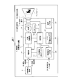
- FIG. 1 is a block diagram showing an outline of a configuration example of a projection type video display apparatus according to an embodiment of the present invention.
- FIG. 2 is a perspective view showing an outline of an example of the appearance of the projection display apparatus according to the present embodiment.
- a projection display apparatus 1 is, for example, a liquid crystal projector that receives an electric power supply from an external power supply 3 and projects an image on a screen 4 to display the enlarged image.
- the projection-type image display device 1 is implemented by, for example, hardware, various devices, and the like, and includes a power supply unit 11, a light source driving unit 12, a light source 13, an illumination optical system 14, a display element 15, a projection optical system 16, and a nonvolatile display.
- the device 17, the processing unit 18, the cooling fan 19, the video signal input unit 20, the memory 21 and the nonvolatile memory 22, the operation input unit 23, the video signal input terminal 24, the power supply connection unit 25, and the power supply line 26 are included. Have.
- the power supply unit 11 receives power supply from the external power supply 3 connected by the power supply line 26 through the power supply connection unit 25, and then the light source driving unit 12, nonvolatile display Drive power is supplied to each unit including the device 17 and the processing unit 18.
- the power supply line 26 is directly switched ON / OFF by connecting / disconnecting the power supply line 26.
- the power supply line 26 is connected by providing a power switch or the like (not shown). You may make it switch ON / OFF of electric power supply by ON / OFF of the said switch.
- the light source driving unit 12 drives the light source 13 to emit light in accordance with control from the processing unit 18 described later.
- the light source 13 for example, a high-pressure mercury lamp, a xenon lamp, an LED (Light Emitting Diode) light source, a laser light source, or the like is used.
- the illumination optical system 14 is an optical system including one or more lenses that converge light emitted from the light source 13.
- the display element 15 is an element that forms an image to be projected based on a video signal from the processing unit 18, and is configured by a transmissive or reflective liquid crystal panel (or a DMD (Digital Micromirror Device: registered trademark) panel) or the like. Is done. An image is projected by transmitting or reflecting the light converged by the illumination optical system 14.
- the projection optical system 16 is an optical system composed of one or more lenses that magnify a projection image from the display element 15 and project the projected image on the screen 4. These units constitute a video projection unit.
- the non-volatile display device 17 is, for example, a device such as electronic paper that constitutes a sub-display provided on the exterior of the projection display 1 as shown in the example of FIG.
- Various types of information are displayed on the display based on the output signal from the processing unit 18 according to the state of the projection display apparatus 1. It is assumed that at least character information is displayed, but an image can be displayed. Since it is nonvolatile, for example, even when the supply of power from the external power supply 3 via the power supply unit 11 is stopped, the display content can be maintained. Details of the control of the display content of the nonvolatile display device 17 will be described later.
- the processing unit 18 starts the formation of the projected image on the display element 15 and the projection of the image by the control of the light source 13 by the operation of a microcomputer or the execution of a program by a CPU (Central Processing Unit), for example, and the nonvolatile display device 17. Such as control of the display content of the projection type video display device 1.
- the cooling fan 19 is a fan for releasing heat generated from the light source 13 to the outside and suppressing the increase in temperature. Even after the projection of the image on the screen 4 is finished and the light source 13 stops emitting light, the processing unit 18 controls to operate until the temperature becomes lower than a predetermined time or a predetermined temperature.
- the video signal input unit 20 receives input of a video signal to be projected from an information processing terminal such as a PC (Personal Computer) (not shown) connected via the video signal input terminal 24 as shown in the example of FIG. , An external interface to be transmitted to the processing unit 18.
- an information processing terminal such as a PC (Personal Computer) (not shown) connected via the video signal input terminal 24 as shown in the example of FIG. , An external interface to be transmitted to the processing unit 18.
- the video signal input terminal 24 may include a plurality of types such as HDMI (High-Definition Multimedia Interface), VGA (Video Graphics Array), and DVI (Digital Visual Interface).
- the memory 21 is a built-in memory of the projection video display device 1.
- the processing unit 18 buffers the video signal input from the video signal input unit 20, and develops various setting information and the like in a table. It is a memory to memorize.
- the memory 21 includes a nonvolatile memory 22 such as a flash memory in addition to a volatile memory such as a DRAM (Dynamic Random Access Memory), and the state of the projection display 1 even when power supply is stopped. Information and various setting information can be held.
- the operation input unit 23 is provided for the projection video display device 1 from the user by operating a button or the like (not shown) via a panel or the like provided on the exterior of the projection video display device 1 as shown in the example of FIG. It is an external interface that receives an input of an instruction and transmits it to the processing unit 18. You may receive operation by the remote control etc. which are not shown in figure.
- a user displays a setting menu screen as described later on the projection screen on the screen 4 or a sub-display (nonvolatile display device 17) by an operation via the operation input unit 23, and registers various setting information and the like. Can do.
- FIG. 3 is a diagram showing an outline of an example of owner identification display.
- the owner identification display is a display for identifying the owner, such as the name of the organization that owns the projection type video display device 1, the name of the person in charge, and the contact information. It shall be possible to register.
- FIG. 3A shows an example in which only the owned organization name is displayed
- FIG. 3B shows an example in which the name of the person in charge is displayed in addition to the owned organization name
- FIG. 3C shows an example of further displaying contact information.
- the user can also register ON / OFF of the display of each information via the setting menu.
- image data designated by the user such as a logo mark of the owned organization may be displayed instead of the owned organization name.
- This image data can be acquired from an external device or an external medium via a data input / output interface such as USB (Universal Serial Bus) (not shown), a network interface, or the like.
- USB Universal Serial Bus
- the owner identification display is not limited to the display pattern described above, and may be a custom display mode in which the user can specify and display an arbitrary character or the like via the setting menu. Further, the display content may be maintained as it is even when the power supply line 26 is disconnected and the power supply is stopped by the function of the nonvolatile display device 17. As a result, the contents of the owner identification display remain without disappearing, so that security such as theft prevention can be improved.
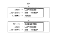
- FIG. 4 is a diagram showing an outline of an example of the operation state display.
- the operation state display is a display that informs the user of information on various states when the light source 13 is turned on, that is, when the projection display 1 is operating.
- FIG. 4A shows an example of displaying each information of the light source state, the input signal identification information, and the input power supply voltage.
- the light source state is information such as a lighting mode of the light source 13 (lamp) such as “normal mode” and “eco mode”, for example.
- the input signal identification information is identification information such as the type of video signal input via the video signal input terminal 24.
- the input power supply voltage is information on the power supply voltage supplied via the power supply connection unit 25.
- FIG. 4B shows an example of displaying each information of the special mode name, the light source state, and the input signal identification information.
- the special mode name is information about whether or not the device is operating in a mode that uses a special function such as an automatic correction function such as edge blending or warping.
- the light source state and input signal identification information are the same as in FIG. 4A, but the display position may be changed as shown in FIG.
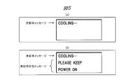
- FIG. 5 is a diagram showing an outline of an example of display during cooling.
- the cooling display is a display that informs the user that the cooling process by the cooling fan 19 is performed after the light source 13 is turned off.
- FIG. 5A is an example in which only a cooling message indicating that cooling is in progress is displayed
- FIG. 5B is an example in which an additional message during cooling indicating further notes and instructions is displayed. Show.
- FIG. 6 is a diagram showing an outline of an example of the replacement part related display.
- the replacement part related display is a display that informs the user of information such as the use time of a replaceable part such as a replaceable light source 13 (lamp) and an intake filter (not shown).
- FIG. 6A is an example of displaying information on the usage time of the filter and the usage time of the light source 13 (lamp), and
- FIG. 6B shows, for example, that the usage time of the filter has exceeded a recommended threshold for replacement
- a replacement recommendation message is displayed in addition to the usage time information is shown. The same applies when the usage time of the light source 13 (lamp) exceeds the threshold value for which replacement is recommended.
- the projection optical system 16 is an interchangeable type
- FIG. 6C shows an example in which the model number of the option lens is displayed.
- the interchangeable lens is not so much exposed from the exterior of the apparatus, and there are many cases where it is not easy to confirm the model.
- a part of the outer cover is removed and the interchangeable lens is directly checked, or the projection display apparatus 1 is activated after the power supply line 26 is connected, and the menu screen is displayed. It was necessary to project the image such as and display the model number and confirm it.
- the model number of the interchangeable lens is displayed on the nonvolatile display device 17 as in the present embodiment, for example, the power supply line 26 is not connected for maintenance work or the like. Even in such a state, the model number of the optional lens can be confirmed, and the efficiency of the maintenance work can be greatly improved.
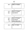
- FIG. 7 is a diagram showing an outline of an example of model attribute identification display.
- the model attribute identification display is, for example, display of attribute information such as the manufacturer (manufacturer), model name (model number), performance (spec), and manufacturing country of the projection display apparatus 1. It is assumed that the unique information of the projection display apparatus 1 is recorded in advance in the nonvolatile memory 22 or the like at the time of manufacture, and protected so that it cannot be changed by the user via a setting menu or the like.
- FIG. 7A shows an example in which only the manufacturer is displayed
- FIG. 7B shows an example in which the model name is displayed in addition to the manufacturer
- FIG. 7C shows an example in which performance information is further displayed
- FIG. 7D shows an example in which only the manufacturing country is displayed.
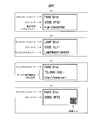
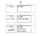
- FIG. 8 and 9 are diagrams showing an outline of examples of error display.
- the error display is a display that informs the user that an error has occurred.
- FIG. 8A shows an example in which the serial number of the main body of the projection display 1 is displayed in addition to the fan error message indicating that an error has occurred in the cooling fan 19 and the display of the error code. Yes.
- FIG. 8B shows an example in which the serial number of the light source 13 (lamp) is displayed in addition to the lamp error message indicating that an error has occurred in the light source 13 (lamp) and its error code. Is shown. The same applies to errors that occur in other parts and parts.
- the content of the error display may be maintained as it is. Thereby, even if the power supply line 26 is not connected again, the content of the error can be transmitted when the user contacts the manufacturer's service department or the like. In addition, even when the projection display apparatus 1 is sent to a dealer or a manufacturer's service department for repair, the person in charge or the like grasps the content of the error without connecting the power supply line 26. Therefore, working efficiency can be improved.
- FIG. 8C shows an example of displaying the information of the contact information or URL (Uniform Resource Locator) of the service department at the store or manufacturer in addition to the display of the fan error message.
- URL Uniform Resource Locator
- FIG. 8D shows an example of displaying an image code for storing information such as the URL of the homepage in addition to the display of the fan error message and its error code.
- a known two-dimensional barcode such as a QR code (registered trademark) can be used as the image code.
- the user can efficiently acquire information regarding the error using a portable information terminal such as a smartphone with a camera or a tablet terminal that can read the image code.
- FIG. 9A shows an example in which only a lamp non-installation error message indicating that a lamp is not installed in the light source 13 is displayed.
- FIG. 9B shows an example of displaying information on the model number of the corresponding lamp that can be mounted in addition to the display of the lamp non-mounting error message.
- FIG. 9C shows an example of displaying the contact information or URL information of the lamp dealer etc. in addition to the display of the lamp non-installation error message.
- the contact information and URL information may be the same as the service department contact information and URL information shown in FIG.
- the display methods shown in the above figures are examples, and the display items, display order, number of display lines, etc. in each figure are not limited to those shown in the figures.
- the display items in each figure may be displayed in combination. Further, for example, the display pattern may be switched as needed based on an instruction from the user via the operation input unit 23.
- FIG. 10 is a diagram showing an outline of an example in which information is displayed in each of two areas, a general state display area and an owner identification display area.
- the owner identification display shown in FIG. 3 is fixedly displayed in the lower owner identification display area, and the upper general state display area is displayed in accordance with the state of the projection display apparatus 1.
- the case where information is displayed is shown.
- 10A shows an example in which the operation state display shown in FIG. 4 is displayed in the general state display area
- FIG. 10B shows the error shown in FIGS. 8 and 9 in the general state display area.
- the example which displays a display is shown.
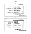
- FIG. 11 is a diagram showing an outline of an example in which information is displayed in two areas of a general state display area and a model attribute identification display.
- the model attribute identification display shown in FIG. 7 is fixedly displayed in the lower model attribute identification display area.
- FIG. 12 is a diagram showing an outline of an example in which information is displayed in each of the three areas.
- FIG. 12A fixedly displays the model attribute identification display shown in FIG. 7 in the middle model attribute identification display area, and the owner identification display shown in FIG. 3 in the lower owner identification display area. Is fixedly displayed, and the operation status display shown in FIG. 4 is displayed in the upper general status display area.
- 12 (b) is different from FIG. 12 (a) in that the replacement part related display of FIG. 6 is fixedly displayed in the middle replacement part related display area, and FIG. 10 shows an example of displaying the error display shown in FIG.
- FIGS. 10 to 12 are also examples, and the display items, the display order, the number of display lines, etc. in each figure are not limited to those shown in the drawings. The number of areas and the division method are not limited to those illustrated. Further, for example, the display pattern may be switched as needed based on an instruction from the user via the operation input unit 23.
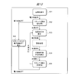
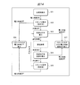
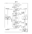
- FIG. 13 to 15 are diagrams showing an outline of an example of transition of screen display contents of the nonvolatile display device 17 under the control of the processing unit 18.
- FIG. 13 is a diagram showing an outline of an example of transition of the screen display content at the normal time.
- S01 initial display state
- S02 standby display
- “before setting” indicates a state in which various types of information are not set by the user via the setting menu. Therefore, not only when the power supply is turned on for the first time immediately after shipment, but also before the setting process is performed, the second and subsequent standby displays are also in this state. An example of specific display contents in each state will be described later.
- the state transits to the light source on-display (S03) state. From this state, when the user performs a setting process via the setting menu and then the light source 13 is turned off and video projection is finished, the state transitions to a state of cooling display (S04) after the light source is turned off. When the cooling is completed, the state transitions to a standby display (after setting) (S05) state. Even when the light source 13 is turned off from the above-described light source lighting display (S03) state, the display is switched directly to the standby display (after setting) (S05) state without performing the cooling display (S04) after the light source is turned off. Good. When the light source 13 is turned on again in the standby display (after setting) (S05) state, the display returns to the light source lighting display state (S03).
- the function of the nonvolatile display device 17 can maintain display of predetermined information even in the absence of power supply.
- FIG. 14 is a diagram showing an outline of an example of transition of screen display contents when power supply is forcibly turned off from other than standby. Since the normal screen transition in FIG. 13 and S01 to S06 are the same, description thereof will be omitted.
- the power supply is forcibly turned off when the projection display 1 is in an operation other than standby, that is, in the state of light source on display (S03), or in the state of cooling display after the light source is turned off (S04).
- the supply line 26 is disconnected, the state transits to a state of forced power supply OFF display (S07) from other than standby.
- the function of the non-volatile display device 17 makes it possible to maintain display of predetermined information even when there is no power supply.
- FIG. 15 is a diagram showing an outline of an example of transition of screen display contents when an error is detected. Since the normal screen transition in FIG. 13 and S01 to S06 are the same, description thereof will be omitted. If the processing unit 18 detects an error in a state where power is supplied to the projection display apparatus 1, that is, in each state of standby display (before setting) (S02) to standby display (after setting) (S05), an error will occur. Transition to the display (S08) state. In the case of the light source on display (S03) state, in addition to the error detection, when the light source 13 is turned off, the state is changed to the error display (S08) state.
- the state transits to the power supply OFF display from error (S09) state. Also in this case, the function of the non-volatile display device 17 makes it possible to maintain display of predetermined information even when there is no power supply.
- Table 1 shows “display switching” as an example of display contents in the screen transition when various information is displayed with the entire display area of the nonvolatile display device 17 as one area as shown in FIGS. Two patterns of “Example 1-1” and “Display switching example 1-2” are shown. “Display switching example 1-1” is a pattern in which the owner identification display shown in FIG. 3 is maintained even after the power supply is turned OFF. “Display switching example 1-2” indicates that the power supply is OFF. This is a pattern for maintaining the replacement part related display shown in FIG.
- any pattern basically displays nothing at the time of shipment (S01) or displays arbitrary information set in advance as other display.
- the model attribute identification display shown in FIG. 7 may be used.
- the standby display (before setting) (S02) nothing is displayed or other display is performed.
- the model attribute identification display shown in FIG. 7 may be used.
- the display content of the shipping display (S01) may be maintained as it is, or the display may be switched. For example, nothing is displayed in the shipping display (S01), but the display may be switched to the model attribute identification display in the standby display (before setting) (S02) when the power supply is turned on.
- the operation state display shown in FIG. 4 is used, and in the cooling display after the light source is turned off (S04), the cooling display shown in FIG.
- the standby display (after setting) S06
- the owner identification display shown in FIG. 3 is shown, and in the case of “display switching example 1-2”, it is shown in FIG. It is a display related to replacement parts. Note that the owner identification display and the replacement part related display are displayed only when display ON is designated by the user via a setting menu to be described later. Furthermore, for the owner identification display, owner information is displayed. It is displayed only when registered by the user.
- the display content in the standby display (S02 or S05) is maintained as it is even if the power supply is turned off.
- the power supply forced OFF display from other than standby (S07) the display contents at the time when the power supply is turned off are maintained as they are.
- the error display (S08) the error display shown in FIGS. 8 and 9 is used.
- the power supply OFF display from an error (S09) even if the power supply is turned OFF, the display content in the error display (S08) is maintained.
- examples of display contents in the screen transition when the display area of the nonvolatile display device 17 is divided into two areas and information is displayed on each of the two areas are as follows: Shown in the table.
- Table 2 shows display areas 1 (for example, FIG. 3) for three patterns of “display switching example 2-1”, “display switching example 2-2”, and “display switching example 2-3”. 10, the upper display area in FIG. 11) and the display area 2 (for example, the lower fixed display area in FIGS. 10 and 11) are displayed.
- Display switching example 2-1 in the table is a pattern in which the owner identification display shown in FIG. 3 is constantly displayed and the owner identification display is maintained even after the power supply is turned off.
- “Display switching example 2-2” is a pattern in which the replacement part related display shown in FIG. 6 is constantly displayed and the replacement part related display is maintained even after the power supply is turned off.
- “Display switching example 2-3” is a pattern in which the model attribute identification display shown in FIG. 7 is constantly displayed and the model attribute identification display is maintained even after the power supply is turned off.
- the display area # 1 may be the model attribute identification display shown in FIG.
- the display area # 2 is set as the model attribute identification display.
- the standby display (before setting) (S02) the display contents of the shipping display (S01) may be maintained as they are, or the display may be switched.
- the display area # 1 is the operation state display shown in FIG. 4 in the light source lighting display (S03), and the display area # 1 is shown in FIG. 5 in the cooling display after the light source is turned off (S04). Use the indicated cooling display.
- display area # 2 in the case of “display switching example 2-1”, the owner identification display shown in FIG.
- the replacement part related display shown in FIG. 6 “display switching example 2-3”, the model attribute identification display shown in FIG. 7 is used.
- the owner identification display and the replacement part related display are displayed only when the display ON is designated by the user via the setting menu described later.
- the person identification display is displayed only when the owner information is registered by the user.
- the standby display (after setting) (S05) for display area # 1, in the case of “display switching example 2-1,” nothing is displayed or a display other than the owner identification display is displayed. In the case of “Display switching example 2-2”, nothing is displayed or a display other than replacement parts related display, and in the case of “display switching example 2-3”, nothing is displayed or a display other than the model attribute identification display. .
- the display area # 2 is the same as in the case of the display during cooling after the light source is turned off (S04).
- the display contents in the standby display (S02 or S05) are maintained as they are for the display area # 1 even when the power supply is turned off.
- the power supply forced OFF display from other than standby (S07) the display content at the time when the power supply is turned off is maintained as it is for display area # 1.
- the error display (S08) the error display shown in FIGS. 8 and 9 is used for the display area # 1.
- the power supply OFF display from an error S09
- the display content in the error display (S08) is maintained for the display area # 1 even if the power supply is turned OFF.
- “display switching example 2-1” corresponds to the display switching pattern for each of power supply OFF display from standby (S06) to power supply OFF display from error (S09).
- 3 is the owner identification display shown in FIG. 3
- “Display switching example 2-2” is the replacement part related display shown in FIG. 6, and “Display switching example 2-3” is shown in FIG. Maintain or display the machine attribute identification display.
- Table 3 shows display areas 1 (for example, FIG. 3) for three patterns “display switching example 3-1”, “display switching example 3-2”, and “display switching example 3-3” as examples of display contents. 12 (the upper area in FIG. 12), the display area 2 (for example, the middle fixed display area in FIG. 12), and the display area 3 (for example, the lower fixed display area in FIG. 12). Is shown.
- Display switching example 3-1 in the table displays the owner identification display shown in FIG. 3 and the replacement part related display shown in FIG. 6 constantly and after the power supply is turned off. Is a pattern that maintains these displays.
- Display switching example 3-2 always displays the model attribute identification display and the replacement part related display shown in FIG. 7 in a fixed manner, and displays these displays even after the power supply is turned off. It is a pattern to maintain.
- Display switching example 3-3 is a pattern in which the model attribute identification display and the owner identification display are constantly displayed in a fixed manner, and these displays are maintained even after the power supply is turned off.
- all of the display areas # 1, # 2, and # 3 are basically the same as those in Table 1. Is not displayed, or other display.
- the display area # 3 is set as the model attribute identification display.
- the display contents of the shipping display (S01) may be maintained as they are, or the display may be switched.
- the display area # 1 is the operation state display shown in FIG. 4 in the light source lighting display (S03), and the display area # 1 is shown in FIG. 5 in the cooling display after the light source is turned off (S04).
- the display area # 2 is owned by the display shown in FIG. 3 for the display areas # 2 and # 3 corresponding to the respective patterns.
- the person identification display and display area # 3 are the replacement part related display shown in FIG.
- the display area # 2 is the replacement part related display
- the display area # 3 is the model attribute identification display shown in FIG.
- the display area # 2 is set as the owner identification display
- the display area # 3 is set as the model attribute identification display.
- the owner identification display and the replacement part related display are displayed only when the display ON is designated by the user via the setting menu described later.
- the person identification display is displayed only when the owner information is registered by the user.
- the display contents in the standby display (S02 or S05) are maintained as they are for the display area # 1 even when the power supply is turned off.
- the power supply forced OFF display from other than standby (S07) the display content at the time when the power supply is turned off is maintained as it is for display area # 1.
- the error display (S08) the error display shown in FIGS. 8 and 9 is used for the display area # 1.
- the power supply OFF display from an error S09
- the display content in the error display (S08) is maintained for the display area # 1 even if the power supply is turned OFF.
- “display switching example” corresponds to the display switching pattern for each of power supply OFF display from standby (S06) to power supply OFF display from error (S09).
- the model attribute identification display “display switching example 3-3”, the owner identification display or the model attribute identification display is maintained or displayed.
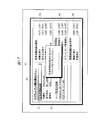
- FIGS. 16 to 19 are diagrams showing an outline of an example of a setting menu screen for setting display contents and the like of the nonvolatile display device 17.
- the setting menu screen 50 is projected as a projected image 41 on the screen 4 according to an instruction from the user via the operation input unit 23, and accepts registration of values and setting contents by the user's operation via the operation input unit 23.
- the owner information registration menu 52 on the left side of the screen is provided with an “owner information registration” field and a “user specified sentence registration” field, of which “owner information registration” field is for input.
- the cursor 51 is focused and indicates that input is currently being accepted.
- this menu in addition to registering / changing owner information consisting of items such as “organization name”, “person in charge”, “contact”, etc., it is possible to accept registration of arbitrary sentences as “user specified sentences” it can.
- the user designation sentence for example, notes for the user can be set together with information for identifying the owner.
- This user-specified sentence may be displayed, for example, instead of the display contents in the owner identification display shown in FIG. 3 as the custom display mode, or may be displayed together with the owner information.
- an owner identification display setting menu 53 On the right side of the screen in FIG. 16, an owner identification display setting menu 53, a replacement part related display setting menu 54, and a model attribute identification display setting menu 55 are provided, and display of each item on the nonvolatile display device 17. ON / OFF can be set by the user.
- the item of attribute information of the projection type video display device 1 such as the model name and performance in the model attribute identification display can only be set ON / OFF of display in the model attribute identification display setting menu 55, and the user can Prevent rewriting of contents. As a result, illegal resale or the like that misrepresents attribute information such as model name and performance can be suppressed.
- owner information or a user-specified sentence in the owner identification display setting menu 53 as shown in the example of FIG. Good.
- the above-mentioned user-specified sentence does not necessarily have to be registered as owner information, and is set independently of owner information registration and owner identification display ON / OFF setting as shown in the example of FIG. You may be able to do it.
- a “user specified sentence registration” field is provided in the independent user specified sentence registration menu 56 to indicate that the cursor 51 is focused.
- ON / OFF setting of the display of the user specified sentence can also be performed in the independent user specified sentence display setting menu 57.
- FIG. 17 when updating the contents of the user-specified sentence in the user-specified sentence registration menu 56, as shown in the example of FIG. You may make it do.
- the non-volatile display device 17 such as electronic paper provided on the exterior of the main body even after the supply of power is stopped. It is possible to maintain display of various information on the sub-display composed of
- security such as theft prevention can be improved by maintaining the owner identification display even when there is no power supply.
- maintaining the replacement part related display even in the absence of power supply can greatly improve the efficiency of the maintenance work.
- unauthorized resale or the like that changes the model attribute information can be suppressed.
- the error display even when there is no power supply the work efficiency for repairs and the like can be greatly improved.
- Each embodiment of the present invention described above is a non-battery-driven projection-type video display in which the light source cannot be turned on and the display change control of the sub-display cannot be performed when the power supply from the external power supply via the power supply line is cut off. It is particularly effective when employed in the apparatus.
- each of the embodiments of the present invention described above is particularly effective when applied to a projection-type video display device that does not include a battery for performing light source lighting and / or sub-display display change control without a power supply line. It is.
- each of the embodiments of the present invention described above is a projection-type image display that performs lighting control of the light source and / or display change control of the sub-display only when power is supplied from the external power supply via the power supply line. It is particularly effective when employed in the apparatus.
- the present invention made by the present inventor has been specifically described based on the embodiments.
- the present invention is not limited to the above-described embodiments, and various modifications can be made without departing from the scope of the invention. Needless to say.
- the above-described embodiment has been described in detail for easy understanding of the present invention, and is not necessarily limited to the one having all the configurations described.
Landscapes
- Physics & Mathematics (AREA)
- General Physics & Mathematics (AREA)
- Engineering & Computer Science (AREA)
- Multimedia (AREA)
- Signal Processing (AREA)
- Computer Security & Cryptography (AREA)
- Optics & Photonics (AREA)
- Controls And Circuits For Display Device (AREA)
- Devices For Indicating Variable Information By Combining Individual Elements (AREA)
- Projection Apparatus (AREA)
- Transforming Electric Information Into Light Information (AREA)
Abstract
Description
図1は、本発明の一実施の形態である投射型映像表示装置の構成例について概要を示したブロック図である。また、図2は、本実施の形態の投射型映像表示装置の外観の例について概要を示した斜視図である。図1において、投射型映像表示装置1は、例えば、外部電源供給3から電力の供給を受けて、スクリーン4に対して映像を投射して拡大表示する液晶プロジェクタ等である。
図3~図12は、不揮発性表示デバイス17の画面に表示される内容の例について概要を示した図である。図3は、所有者識別表示の例について概要を示した図である。所有者識別表示は、当該投射型映像表示装置1を所有する組織名や担当者名、連絡先等の所有者を識別する表示であり、表示内容は、ユーザが後述する設定メニュー画面を介して登録することができるものとする。
図13~図15は、処理部18の制御による不揮発性表示デバイス17の画面表示内容の遷移の例について概要を示した図である。図13は、正常時の画面表示内容の遷移の例について概要を示した図である。まず、初期状態の出荷時表示(S01)の状態から最初に電力供給がONされる、すなわち外部電源供給3との間で電力供給線26が接続されると、スタンバイ表示(設定前)(S02)の状態に遷移する。ここで「設定前」とは、設定メニューを介したユーザによる各種情報の設定処理がされていない状態を指す。したがって、出荷直後の初回の電力供給ON時はもちろん、設定処理がされる前であれば2回目以降のスタンバイ表示についてもこの状態となる。なお、各状態での具体的な表示内容の例については後述する。

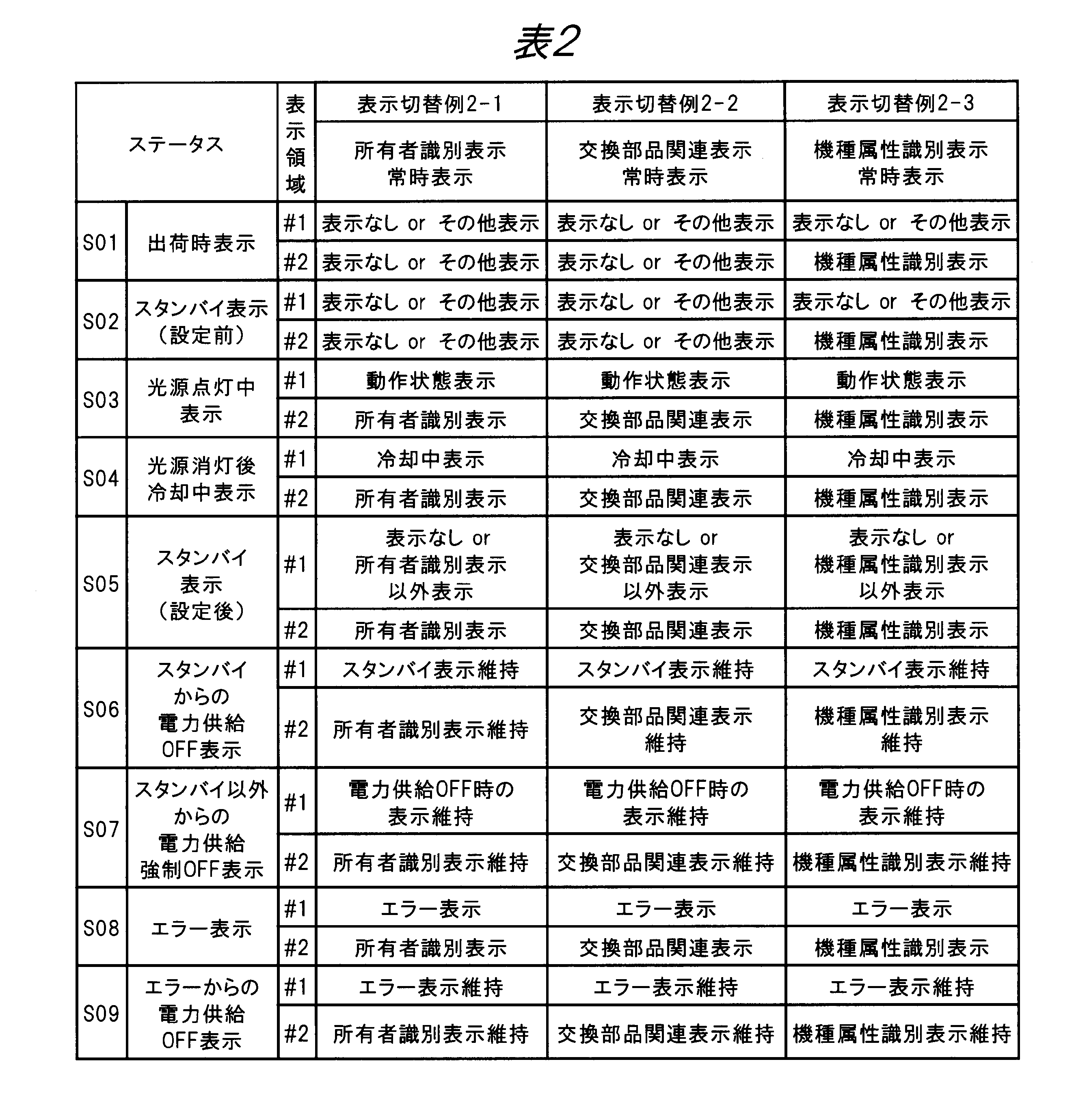

図16~図19は、不揮発性表示デバイス17の表示内容等を設定する設定メニュー画面の例について概要を示した図である。設定メニュー画面50は、例えば、操作入力部23を介したユーザによる指示によりスクリーン4上に投射映像41として投射され、操作入力部23を介したユーザの操作による値や設定内容の登録を受け付ける。
11…電源部、12…光源駆動部、13…光源、14…照明光学系、15…表示素子、16…投射光学系、17…不揮発性表示デバイス、18…処理部、19…冷却ファン、20…映像信号入力部、21…メモリ、22…不揮発性メモリ、23…操作入力部、24…映像信号入力端子、25…電源接続部、26…電力供給線、41…投射映像、50…設定メニュー画面、51…カーソル、52…所有者情報登録メニュー、53…所有者識別表示設定メニュー、54…交換部品関連表示設定メニュー、55…機種属性識別表示設定メニュー、56…ユーザ指定文登録メニュー、57…ユーザ指定文表示設定メニュー
Claims (13)
- 光源からの光を用いて映像を投射する映像投射部を有する投射型映像表示装置であって、
前記投射型映像表示装置で用いる電力を外部から供給するための電力供給線を接続する電源接続部と、
前記映像投射部とは別に設けられた、少なくとも文字情報を表示する不揮発性表示デバイスと、
前記不揮発性表示デバイスに対して1つ以上の所定の項目の情報を表示させる処理部と、を有し、
前記電源接続部に前記電力供給線が接続されていない状態であっても、前記不揮発性表示デバイスに情報を表示した状態を維持する、投射型映像表示装置。 - 請求項1に記載の投射型映像表示装置において、
前記不揮発性表示デバイスは、前記所定の項目として、前記投射型映像表示装置の所有者を識別するための情報である所有者識別情報を表示する、投射型映像表示装置。 - 請求項1に記載の投射型映像表示装置において、
前記不揮発性表示デバイスは、前記所定の項目として、前記投射型映像表示装置における交換可能部品に係る情報である交換部品関連情報を表示する、投射型映像表示装置。 - 請求項1に記載の投射型映像表示装置において、
前記不揮発性表示デバイスは、前記所定の項目として、前記投射型映像表示装置の固有の属性情報である機種属性識別情報を表示する、投射型映像表示装置。 - 請求項1に記載の投射型映像表示装置において、
前記不揮発性表示デバイスは、前記所定の項目として、前記投射型映像表示装置において検知したエラーに係る情報を表示する、投射型映像表示装置。 - 請求項1に記載の投射型映像表示装置において、
さらに、ユーザによる操作を受け付ける操作入力部を有し、
前記操作入力部を介した指示により、前記所定の項目毎に、前記処理部が前記不揮発性表示デバイスに表示させるか否かについての設定を受け付けることが可能である、投射型映像表示装置。 - 請求項2に記載の投射型映像表示装置において、
さらに、ユーザによる操作を受け付ける操作入力部を有し、
前記操作入力部を介した指示により、前記所有者識別情報の内容を更新することが可能である、投射型映像表示装置。 - 請求項7に記載の投射型映像表示装置において、
前記操作入力部を介して所定のパスワードが入力された場合に限り前記所有者識別情報の内容を更新する、投射型映像表示装置。 - 請求項4に記載の投射型映像表示装置において、
前記機種属性識別情報については更新を不可とする、投射型映像表示装置。 - 請求項1に記載の投射型映像表示装置において、
前記不揮発性表示デバイスは、1つ以上の前記所定の項目を表示することができる領域を1つ以上有し、前記領域のうち少なくとも1つ以上は、前記投射型映像表示装置の状態に関わらず表示内容が固定されている、投射型映像表示装置。 - 請求項1に記載の投射型映像表示装置において、
前記不揮発性表示デバイスは、1つ以上の前記所定の項目を表示することができる領域を1つ以上有し、前記領域のうち少なくとも1つ以上は、前記投射型映像表示装置の状態に応じて表示内容が切り替わる、投射型映像表示装置。 - 請求項1に記載の投射型映像表示装置において、
前記電源接続部に前記電力供給線が接続されており電力が外部から供給されているときのみ前記光源の点灯を行う、投射型映像表示装置。 - 光源からの光を用いて映像を投射する映像投射部を有する投射型映像表示装置における情報表示方法であって、
前記投射型映像表示装置は、前記投射型映像表示装置で用いる電力を外部から供給するための電力供給線を接続する電源接続部と、前記映像投射部とは別に設けられた、少なくとも文字情報を表示する不揮発性表示デバイスと、前記不揮発性表示デバイスに対して1つ以上の所定の項目の情報を表示させる処理部と、を有し、
前記電源接続部から前記電力供給線の接続が外された際に、前記不揮発性表示デバイスに情報を表示した状態を維持する、投射型映像表示装置における情報表示方法。
Priority Applications (4)
| Application Number | Priority Date | Filing Date | Title |
|---|---|---|---|
| PCT/JP2015/061731 WO2016166868A1 (ja) | 2015-04-16 | 2015-04-16 | 投射型映像表示装置および投射型映像表示装置における情報表示方法 |
| US15/566,227 US10564535B2 (en) | 2015-04-16 | 2015-04-16 | Projection type image display apparatus and information display method on projection type image display apparatus |
| CN201580078763.0A CN107615163A (zh) | 2015-04-16 | 2015-04-16 | 投射型影像显示装置以及投射型影像显示装置中的信息显示方法 |
| JP2017512151A JP6678164B2 (ja) | 2015-04-16 | 2015-04-16 | 投射型映像表示装置 |
Applications Claiming Priority (1)
| Application Number | Priority Date | Filing Date | Title |
|---|---|---|---|
| PCT/JP2015/061731 WO2016166868A1 (ja) | 2015-04-16 | 2015-04-16 | 投射型映像表示装置および投射型映像表示装置における情報表示方法 |
Publications (1)
| Publication Number | Publication Date |
|---|---|
| WO2016166868A1 true WO2016166868A1 (ja) | 2016-10-20 |
Family
ID=57125788
Family Applications (1)
| Application Number | Title | Priority Date | Filing Date |
|---|---|---|---|
| PCT/JP2015/061731 Ceased WO2016166868A1 (ja) | 2015-04-16 | 2015-04-16 | 投射型映像表示装置および投射型映像表示装置における情報表示方法 |
Country Status (4)
| Country | Link |
|---|---|
| US (1) | US10564535B2 (ja) |
| JP (1) | JP6678164B2 (ja) |
| CN (1) | CN107615163A (ja) |
| WO (1) | WO2016166868A1 (ja) |
Families Citing this family (5)
| Publication number | Priority date | Publication date | Assignee | Title |
|---|---|---|---|---|
| JP6911831B2 (ja) * | 2016-03-18 | 2021-07-28 | ソニーグループ株式会社 | プロジェクター |
| JP7404891B2 (ja) * | 2020-01-28 | 2023-12-26 | セイコーエプソン株式会社 | プロジェクターの制御方法及びプロジェクター |
| CN111615238A (zh) * | 2020-06-05 | 2020-09-01 | 太仓电威光电有限公司 | 智能控制器和应用其的影视灯具 |
| US11698624B2 (en) | 2020-09-23 | 2023-07-11 | Rockwell Automation Technologies, Inc. | Actuation assembly for display for industrial automation component |
| US11493904B2 (en) * | 2020-09-23 | 2022-11-08 | Rockwell Automation Technologies, Inc. | Error display for industrial automation component |
Citations (4)
| Publication number | Priority date | Publication date | Assignee | Title |
|---|---|---|---|---|
| JP2003209718A (ja) * | 2002-01-10 | 2003-07-25 | Fuji Photo Film Co Ltd | 電子機器 |
| JP2006039448A (ja) * | 2004-07-30 | 2006-02-09 | Seiko Epson Corp | 電子機器、ケーブル、及び電子機器システム |
| JP2008233599A (ja) * | 2007-03-22 | 2008-10-02 | Seiko Epson Corp | 表示装置付きプロジェクタ及び電子機器 |
| JP2010276818A (ja) * | 2009-05-28 | 2010-12-09 | Seiko Epson Corp | プロジェクター |
Family Cites Families (19)
| Publication number | Priority date | Publication date | Assignee | Title |
|---|---|---|---|---|
| JP3697919B2 (ja) * | 1998-12-18 | 2005-09-21 | コニカミノルタホールディングス株式会社 | 反射型表示素子を用いた映像表示装置 |
| JP3726824B2 (ja) | 1999-03-12 | 2005-12-14 | コニカミノルタホールディングス株式会社 | 液晶表示装置及び表示システム |
| JP2000330526A (ja) | 1999-03-12 | 2000-11-30 | Minolta Co Ltd | 液晶表示装置、携帯電子機器及び駆動方法 |
| JP3704318B2 (ja) | 2002-03-25 | 2005-10-12 | 日本電信電話株式会社 | インターネットアクセス機能を持つ携帯装置を用いたユーザ認証システム及びそのユーザ認証装置 |
| JP4151325B2 (ja) * | 2002-07-02 | 2008-09-17 | 株式会社ニコン | 電子カメラ |
| JP2005152373A (ja) | 2003-11-26 | 2005-06-16 | Daiman:Kk | 遊技機 |
| JP2005221898A (ja) | 2004-02-06 | 2005-08-18 | Matsushita Electric Ind Co Ltd | プロジェクタシステム、プロジェクタ装置、端末装置、投射方法、光指示装置、光指示方法、プログラム、及び記録媒体 |
| JP2006091112A (ja) * | 2004-09-21 | 2006-04-06 | Nikon Corp | 電子機器 |
| US20080004919A1 (en) * | 2006-06-30 | 2008-01-03 | Rearden Commerce, Inc. | Triggered transactions based on criteria |
| JP2008112306A (ja) * | 2006-10-30 | 2008-05-15 | Toshiba Corp | 情報処理装置および情報処理方法 |
| JP2008121849A (ja) * | 2006-11-15 | 2008-05-29 | Matsushita Electric Ind Co Ltd | 動圧流体軸受装置、スピンドルモータおよび記録再生装置 |
| EP2127367B1 (en) * | 2007-02-20 | 2017-03-29 | Daegu Gyeongbuk Institute Of Science&Technology | Multimedia player displaying 2 projection images |
| JP2010086089A (ja) | 2008-09-29 | 2010-04-15 | Brother Ind Ltd | 携帯型表示端末及びプログラム |
| JP5434418B2 (ja) * | 2009-09-15 | 2014-03-05 | セイコーエプソン株式会社 | プロジェクターシステム、制御装置、プログラム及びプロジェクターシステムの制御方法 |
| JP2011221739A (ja) | 2010-04-08 | 2011-11-04 | Canon Inc | データ処理方法 |
| US8382295B1 (en) * | 2010-06-30 | 2013-02-26 | Amazon Technologies, Inc. | Optical assembly for electronic devices |
| JP2012150082A (ja) | 2011-01-21 | 2012-08-09 | Aisin Aw Co Ltd | ナビゲーション装置、ナビゲーション方法およびナビゲーションプログラム |
| CN104115065B (zh) * | 2012-02-09 | 2018-04-24 | 日立麦克赛尔株式会社 | 投影型影像显示装置 |
| CN202929343U (zh) * | 2012-11-12 | 2013-05-08 | 天津开发区华普惠诚网络科技有限公司 | 一种投影仪 |
-
2015
- 2015-04-16 WO PCT/JP2015/061731 patent/WO2016166868A1/ja not_active Ceased
- 2015-04-16 US US15/566,227 patent/US10564535B2/en not_active Expired - Fee Related
- 2015-04-16 CN CN201580078763.0A patent/CN107615163A/zh active Pending
- 2015-04-16 JP JP2017512151A patent/JP6678164B2/ja not_active Expired - Fee Related
Patent Citations (4)
| Publication number | Priority date | Publication date | Assignee | Title |
|---|---|---|---|---|
| JP2003209718A (ja) * | 2002-01-10 | 2003-07-25 | Fuji Photo Film Co Ltd | 電子機器 |
| JP2006039448A (ja) * | 2004-07-30 | 2006-02-09 | Seiko Epson Corp | 電子機器、ケーブル、及び電子機器システム |
| JP2008233599A (ja) * | 2007-03-22 | 2008-10-02 | Seiko Epson Corp | 表示装置付きプロジェクタ及び電子機器 |
| JP2010276818A (ja) * | 2009-05-28 | 2010-12-09 | Seiko Epson Corp | プロジェクター |
Also Published As
| Publication number | Publication date |
|---|---|
| JP6678164B2 (ja) | 2020-04-08 |
| CN107615163A (zh) | 2018-01-19 |
| JPWO2016166868A1 (ja) | 2018-03-15 |
| US10564535B2 (en) | 2020-02-18 |
| US20180101089A1 (en) | 2018-04-12 |
Similar Documents
| Publication | Publication Date | Title |
|---|---|---|
| JP6678164B2 (ja) | 投射型映像表示装置 | |
| CN107408371B (zh) | 显示装置、终端装置以及显示系统 | |
| US20040196442A1 (en) | Method and system for control of display lamp illumination with lens cap position | |
| CN103913842A (zh) | 显示装置以及显示装置的控制方法 | |
| US10768884B2 (en) | Communication apparatus, display apparatus, control method thereof, storage medium, and display system for configuring multi-display settings | |
| JP6500889B2 (ja) | プロジェクターおよびプロジェクターの制御方法 | |
| US7188958B2 (en) | Projection arrangement and electronic customer device | |
| CN106249528A (zh) | 光源装置以及投影仪 | |
| CN115834846B (zh) | 图像显示方法及投影仪 | |
| US20150160742A1 (en) | Image display device, projector, and control method for image display device | |
| JP2009048022A (ja) | プロジェクタ | |
| US20090180076A1 (en) | Projector with service information displaying function and service information displaying method for use with such projector | |
| JP2011180260A (ja) | 投写型映像表示装置 | |
| JP6369082B2 (ja) | プロジェクター、表示装置、およびプロジェクターの制御方法 | |
| JP2009049625A (ja) | 電子機器、プロジェクタ、及び電子機器の制御方法 | |
| JP4930684B2 (ja) | Tvおよびtv用データ転送制御方法 | |
| JP2022132791A5 (ja) | ||
| JP2021068145A (ja) | 頭部装着型表示装置の動作方法および頭部装着型表示装置 | |
| JP2016008999A (ja) | プロジェクター、およびプロジェクターの制御方法 | |
| JP2010210967A (ja) | プロジェクター、プログラムおよびプロジェクターの起動方法 | |
| JP2013020058A (ja) | プロジェクター、及びプロジェクターの制御方法 | |
| JP2009063959A (ja) | プロジェクタ及びその制御方法 | |
| JP2004294743A (ja) | 情報投影装置 | |
| JP2012226034A (ja) | プロジェクターシステム、及びプロジェクターシステムの制御方法 | |
| JP2007212619A (ja) | 投射型画像表示装置 |
Legal Events
| Date | Code | Title | Description |
|---|---|---|---|
| 121 | Ep: the epo has been informed by wipo that ep was designated in this application |
Ref document number: 15889206 Country of ref document: EP Kind code of ref document: A1 |
|
| ENP | Entry into the national phase |
Ref document number: 2017512151 Country of ref document: JP Kind code of ref document: A |
|
| WWE | Wipo information: entry into national phase |
Ref document number: 15566227 Country of ref document: US |
|
| NENP | Non-entry into the national phase |
Ref country code: DE |
|
| 122 | Ep: pct application non-entry in european phase |
Ref document number: 15889206 Country of ref document: EP Kind code of ref document: A1 |