WO2016163513A1 - インクジェット装置のギャップ調整方法及びインクジェット装置 - Google Patents
インクジェット装置のギャップ調整方法及びインクジェット装置 Download PDFInfo
- Publication number
- WO2016163513A1 WO2016163513A1 PCT/JP2016/061526 JP2016061526W WO2016163513A1 WO 2016163513 A1 WO2016163513 A1 WO 2016163513A1 JP 2016061526 W JP2016061526 W JP 2016061526W WO 2016163513 A1 WO2016163513 A1 WO 2016163513A1
- Authority
- WO
- WIPO (PCT)
- Prior art keywords
- ink
- gap
- landing
- landing position
- carriage
- Prior art date
- Legal status (The legal status is an assumption and is not a legal conclusion. Google has not performed a legal analysis and makes no representation as to the accuracy of the status listed.)
- Ceased
Links
Images






Classifications
-
- B—PERFORMING OPERATIONS; TRANSPORTING
- B41—PRINTING; LINING MACHINES; TYPEWRITERS; STAMPS
- B41J—TYPEWRITERS; SELECTIVE PRINTING MECHANISMS, i.e. MECHANISMS PRINTING OTHERWISE THAN FROM A FORME; CORRECTION OF TYPOGRAPHICAL ERRORS
- B41J3/00—Typewriters or selective printing or marking mechanisms characterised by the purpose for which they are constructed
- B41J3/407—Typewriters or selective printing or marking mechanisms characterised by the purpose for which they are constructed for marking on special material
- B41J3/4073—Printing on three-dimensional objects not being in sheet or web form, e.g. spherical or cubic objects
- B41J3/40731—Holders for objects, e. g. holders specially adapted to the shape of the object to be printed or adapted to hold several objects
-
- B—PERFORMING OPERATIONS; TRANSPORTING
- B41—PRINTING; LINING MACHINES; TYPEWRITERS; STAMPS
- B41J—TYPEWRITERS; SELECTIVE PRINTING MECHANISMS, i.e. MECHANISMS PRINTING OTHERWISE THAN FROM A FORME; CORRECTION OF TYPOGRAPHICAL ERRORS
- B41J11/00—Devices or arrangements of selective printing mechanisms, e.g. ink-jet printers or thermal printers, for supporting or handling copy material in sheet or web form
- B41J11/008—Controlling printhead for accurately positioning print image on printing material, e.g. with the intention to control the width of margins
-
- B—PERFORMING OPERATIONS; TRANSPORTING
- B41—PRINTING; LINING MACHINES; TYPEWRITERS; STAMPS
- B41J—TYPEWRITERS; SELECTIVE PRINTING MECHANISMS, i.e. MECHANISMS PRINTING OTHERWISE THAN FROM A FORME; CORRECTION OF TYPOGRAPHICAL ERRORS
- B41J11/00—Devices or arrangements of selective printing mechanisms, e.g. ink-jet printers or thermal printers, for supporting or handling copy material in sheet or web form
- B41J11/20—Platen adjustments for varying the strength of impression, for a varying number of papers, for wear or for alignment, or for print gap adjustment
-
- B—PERFORMING OPERATIONS; TRANSPORTING
- B41—PRINTING; LINING MACHINES; TYPEWRITERS; STAMPS
- B41J—TYPEWRITERS; SELECTIVE PRINTING MECHANISMS, i.e. MECHANISMS PRINTING OTHERWISE THAN FROM A FORME; CORRECTION OF TYPOGRAPHICAL ERRORS
- B41J2/00—Typewriters or selective printing mechanisms characterised by the printing or marking process for which they are designed
- B41J2/005—Typewriters or selective printing mechanisms characterised by the printing or marking process for which they are designed characterised by bringing liquid or particles selectively into contact with a printing material
- B41J2/01—Ink jet
-
- B—PERFORMING OPERATIONS; TRANSPORTING
- B41—PRINTING; LINING MACHINES; TYPEWRITERS; STAMPS
- B41J—TYPEWRITERS; SELECTIVE PRINTING MECHANISMS, i.e. MECHANISMS PRINTING OTHERWISE THAN FROM A FORME; CORRECTION OF TYPOGRAPHICAL ERRORS
- B41J2/00—Typewriters or selective printing mechanisms characterised by the printing or marking process for which they are designed
- B41J2/005—Typewriters or selective printing mechanisms characterised by the printing or marking process for which they are designed characterised by bringing liquid or particles selectively into contact with a printing material
- B41J2/01—Ink jet
- B41J2/015—Ink jet characterised by the jet generation process
- B41J2/04—Ink jet characterised by the jet generation process generating single droplets or particles on demand
- B41J2/045—Ink jet characterised by the jet generation process generating single droplets or particles on demand by pressure, e.g. electromechanical transducers
- B41J2/04501—Control methods or devices therefor, e.g. driver circuits, control circuits
- B41J2/04505—Control methods or devices therefor, e.g. driver circuits, control circuits aiming at correcting alignment
-
- B—PERFORMING OPERATIONS; TRANSPORTING
- B41—PRINTING; LINING MACHINES; TYPEWRITERS; STAMPS
- B41J—TYPEWRITERS; SELECTIVE PRINTING MECHANISMS, i.e. MECHANISMS PRINTING OTHERWISE THAN FROM A FORME; CORRECTION OF TYPOGRAPHICAL ERRORS
- B41J2/00—Typewriters or selective printing mechanisms characterised by the printing or marking process for which they are designed
- B41J2/005—Typewriters or selective printing mechanisms characterised by the printing or marking process for which they are designed characterised by bringing liquid or particles selectively into contact with a printing material
- B41J2/01—Ink jet
- B41J2/21—Ink jet for multi-colour printing
- B41J2/2132—Print quality control characterised by dot disposition, e.g. for reducing white stripes or banding
- B41J2/2135—Alignment of dots
-
- B—PERFORMING OPERATIONS; TRANSPORTING
- B41—PRINTING; LINING MACHINES; TYPEWRITERS; STAMPS
- B41J—TYPEWRITERS; SELECTIVE PRINTING MECHANISMS, i.e. MECHANISMS PRINTING OTHERWISE THAN FROM A FORME; CORRECTION OF TYPOGRAPHICAL ERRORS
- B41J25/00—Actions or mechanisms not otherwise provided for
- B41J25/304—Bodily-movable mechanisms for print heads or carriages movable towards or from paper surface
- B41J25/308—Bodily-movable mechanisms for print heads or carriages movable towards or from paper surface with print gap adjustment mechanisms
-
- B—PERFORMING OPERATIONS; TRANSPORTING
- B41—PRINTING; LINING MACHINES; TYPEWRITERS; STAMPS
- B41J—TYPEWRITERS; SELECTIVE PRINTING MECHANISMS, i.e. MECHANISMS PRINTING OTHERWISE THAN FROM A FORME; CORRECTION OF TYPOGRAPHICAL ERRORS
- B41J29/00—Details of, or accessories for, typewriters or selective printing mechanisms not otherwise provided for
- B41J29/38—Drives, motors, controls or automatic cut-off devices for the entire printing mechanism
-
- B—PERFORMING OPERATIONS; TRANSPORTING
- B41—PRINTING; LINING MACHINES; TYPEWRITERS; STAMPS
- B41J—TYPEWRITERS; SELECTIVE PRINTING MECHANISMS, i.e. MECHANISMS PRINTING OTHERWISE THAN FROM A FORME; CORRECTION OF TYPOGRAPHICAL ERRORS
- B41J29/00—Details of, or accessories for, typewriters or selective printing mechanisms not otherwise provided for
- B41J29/46—Applications of alarms, e.g. responsive to approach of end of line
-
- B—PERFORMING OPERATIONS; TRANSPORTING
- B41—PRINTING; LINING MACHINES; TYPEWRITERS; STAMPS
- B41J—TYPEWRITERS; SELECTIVE PRINTING MECHANISMS, i.e. MECHANISMS PRINTING OTHERWISE THAN FROM A FORME; CORRECTION OF TYPOGRAPHICAL ERRORS
- B41J3/00—Typewriters or selective printing or marking mechanisms characterised by the purpose for which they are constructed
- B41J3/407—Typewriters or selective printing or marking mechanisms characterised by the purpose for which they are constructed for marking on special material
- B41J3/4073—Printing on three-dimensional objects not being in sheet or web form, e.g. spherical or cubic objects
Definitions
- the present invention relates to a gap adjusting method for an ink jet apparatus that adjusts the length of a gap between an ink discharge port and a landing target, and an ink jet apparatus.
- Patent Document 1 discloses a method of measuring a gap with a photosensor and adjusting the length of the gap according to the measurement result.
- Patent Document 2 discloses an ink jet head inspection method in which a calibration curve indicating a gap between a landing position deviation and a gap is created and a positional deviation distance of an ink discharge port is detected according to the calibration curve.
- the present invention has been made in view of the above, and an object of the present invention is to provide an ink jet device gap adjusting method and an ink jet device that can improve convenience even if the ink jet device has a simple configuration.
- a gap adjusting method for an ink jet apparatus includes a head unit having an ink discharge port from which ink is discharged, the head unit being provided, and a main scanning direction.
- a gap adjusting method for an ink jet apparatus comprising: a carriage that moves to a position of the ink jet; a landing target provided with a gap from the ink discharge port; and a gap adjusting unit that adjusts a length of the gap.
- ink is ejected from the ink ejection port and ink droplets are landed in the forward path of the carriage.
- the forward landing position which is a position on the landing target, and the ink in the return path of the carriage Discharger for landing ink droplets on the return landing position, which is the position on the landing target for landing the droplets.
- an actual measurement value based on the forward landing position and the return landing position where the ink droplet actually landed in the ejection step, and each of the forward landing position and the return landing position determined in advance according to a desired gap.
- ink is ejected in each of the outward and return paths in the ejection process, and in the gap adjustment process, based on the optimum value based on the optimum landing position determined in advance and the actual value based on the landing position formed in the ejection process,
- the length of the gap is adjusted by the gap adjusting means. For this reason, the length of the gap can be adjusted without using an expensive sensor such as a photosensor.
- the gap adjustment means adjusts the length of the gap based on the optimal value based on the optimal landing position determined in advance and the actual measurement value based on the landing position formed by the discharge process, so that it can be adapted to changes in the environment, etc. This eliminates the need to re-create a calibration curve, improving convenience. Therefore, in the gap adjustment method for an inkjet apparatus according to the present invention, the convenience can be improved even if the inkjet apparatus has a simple configuration.
- the gap length may be adjusted based on a distance of the actually measured values of the forward landing position and the backward landing position and / or a positional relationship with each other in the main scanning direction. Preferably based on *
- the degree of adjustment of the gap length is determined based on the actually measured values based on the forward landing position and the backward landing position, so that the ink is landed while moving the carriage at least once in the forward path and the backward path.
- the degree of adjusting the length of the can be determined. Therefore, according to the present invention, the length of the gap can be quickly adjusted even if the ink jet apparatus has a simple configuration.
- the ink droplets are landed at three or more locations in each of the forward path and the backward path, and the interval of ejecting the ink in the forward path and the ink in the backward path are set. It is preferable that the discharge interval is different.
- a movement speed of the carriage is constant when the ink is ejected from the ink ejection port in the ejection step.
- the moving speed of the carriage is constant, it is possible to easily grasp the gap that is the optimum value based on the optimum landing position.
- the deviation width of the actual measurement values based on the forward landing position and the backward landing position is constant, so that the determination can be easily performed.
- the degree of adjusting the gap length in the gap adjustment process based on the information that contributes to the determination can be quickly determined even with a simple configuration of the inkjet device, and convenience can be improved.
- the ink is landed on a thin film that is detachably attached to the landing target in the ejection step.
- the landing object since the discharging step is performed on the thin film that is detachably attached to the landing object, the landing object can be used as a print medium on which the ink jet apparatus prints. Therefore, in the present invention, since the gap length can be adjusted by actually landing the ink on the print medium, the gap length can be surely affected without affecting the dimensional variation of the print medium. Adjustments can be made. Moreover, since the peelable thin film is used, the length of the gap can be adjusted without soiling the print medium. *
- the interval for discharging the ink that causes the ink droplets to land on the three or more places on the forward path is constant, and the three or more places on the return path It is preferable that the interval at which the ink for landing the ink droplets is ejected is constant.
- the interval at which the ink is ejected in each of the forward path and the backward path is constant, the degree to which the gap length is adjusted based on the actually measured value based on the landing position formed by ejecting the ink is adjusted. Even a simple configuration can be quickly determined.
- an ink jet apparatus includes a head portion having an ink discharge port from which ink is discharged, and a carriage that is provided with the head portion and moves in the main scanning direction.
- An ink jet apparatus including a landing object provided with a gap from the ink discharge port, and a gap adjusting unit that adjusts a length of the gap, wherein the carriage is reciprocated in the main scanning direction.
- the forward landing position which is a position on the landing target for discharging ink from the ink discharge port and landing the ink droplet on the forward path of the carriage, and the landing target for landing the ink drop on the return path of the carriage
- a check pattern is formed on the landing target by causing ink droplets to land on the return landing position, which is the upper position.
- the length of the gap by the gap adjusting means based on the check pattern, characterized in that it is adjusted.
- the length of the gap is adjusted by the gap adjusting means based on the actual measurement value based on the landing position formed by ejecting ink in each of the forward and backward paths. For this reason, the length of the gap can be adjusted without using an expensive sensor such as a photosensor. Further, since the gap length is adjusted by the gap adjusting means based on the check pattern, it is not necessary to re-create a calibration curve according to a change in the environment, and the convenience can be improved. Therefore, the ink jet apparatus can have a simple configuration and improve convenience. *
- the ink jet apparatus when the check pattern is formed, position determination that determines the forward landing position and the backward landing position of the landing target in the sub scanning direction orthogonal to the main scanning direction and the main scanning direction. And a head position adjusting means for positioning the ink discharge port at an appropriate position with respect to the forward landing position and the backward landing position.
- the forward landing position and the return landing position of the ink on the landing target can be determined, and the ink discharge port is located at an appropriate position with respect to the forward landing position and the return landing position. Can be positioned. Therefore, the ink jet apparatus can reliably form the check pattern at a predetermined position of the landing target.
- the gap adjustment of the ink jet apparatus can be performed with a simple configuration and improved convenience.
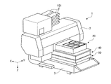
- FIG. 1 is a diagram illustrating a schematic configuration of an ink jet printer in which a gap length is adjusted by a gap adjusting method of an ink jet apparatus according to an embodiment.
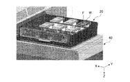
- FIG. 2 is a perspective view illustrating a schematic configuration of the ink jet printer in which the length of the gap is adjusted by the gap adjusting method of the ink jet apparatus according to the embodiment.
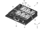
- 3 is a perspective view illustrating a print medium holding unit and a gap driving unit of the ink jet printer illustrated in FIG.
- FIG. 4 is a perspective view showing a print medium holding unit of the ink jet printer shown in FIG.
- FIG. 5 is a block diagram showing a schematic configuration of the inkjet printer shown in FIG. FIG.
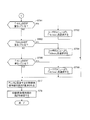
- FIG. 6 is a diagram illustrating a part of a flow illustrating an example of a gap adjusting method of the ink jet apparatus according to the embodiment.
- FIG. 7 is a diagram illustrating the remainder of the flow illustrating an example of the gap adjustment method for the inkjet device according to the embodiment.
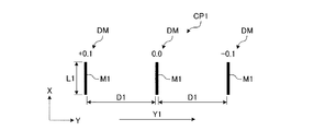
- FIG. 8 is a diagram illustrating a check pattern in the forward path of the gap adjustment method of the ink jet apparatus according to the embodiment.
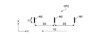
- FIG. 9 is a diagram illustrating a check pattern at the time of return in the gap adjusting method of the ink jet apparatus according to the embodiment.
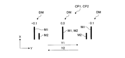
- FIG. 10 is a diagram illustrating a check pattern for the forward path and the return path when the gap of the gap adjustment method for the inkjet apparatus according to the embodiment is an appropriate value.
- FIG. 11 is a diagram illustrating a check pattern for the forward path and the return path when the gap of the gap adjustment method of the ink jet apparatus according to the embodiment is 0.1 mm shorter than an appropriate value.
- FIG. 12 is a diagram illustrating a check pattern for the forward path and the return path when the gap of the gap adjustment method of the ink jet apparatus according to the embodiment is 0.1 mm longer than an appropriate value.
- FIG. 13 is a diagram illustrating a check pattern for the forward path and the return path when the gap of the gap adjustment method of the inkjet device according to the embodiment is 0.2 mm shorter than an appropriate value.
- FIG. 14 is a diagram illustrating check patterns for the forward path and the return path when the gap of the gap adjustment method of the ink jet apparatus according to the embodiment is 0.2 mm longer than an appropriate value.
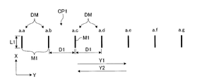
- FIG. 15 is a diagram illustrating a check pattern during a forward path of a gap adjustment method for an inkjet apparatus according to a modification of the embodiment.
- FIG. 16 is a diagram illustrating a check pattern at the time of a return pass in the gap adjustment method for the ink jet device according to the modification of the embodiment.
- FIG. 17 is a diagram illustrating an example of a check pattern formed on a printing surface of a printing medium in a gap adjustment method for an inkjet device according to a modification of the embodiment.
- FIG. 1 is a diagram illustrating a schematic configuration of an ink jet printer in which a gap length is adjusted by a gap adjusting method of an ink jet apparatus according to an embodiment.
- FIG. 2 is a perspective view illustrating a schematic configuration of the ink jet printer in which the length of the gap is adjusted by the gap adjusting method of the ink jet apparatus according to the embodiment.
- 3 is a perspective view illustrating a print medium holding unit and a gap driving unit of the ink jet printer illustrated in FIG.
- FIG. 4 is a perspective view showing a print medium holding unit of the ink jet printer shown in FIG.
- FIG. 5 is a block diagram showing a schematic configuration of the inkjet printer shown in FIG. *
- the ink jet printer 1 shown in FIGS. 1 to 3 as an example of the ink jet apparatus includes a head portion 11 having a plurality of ink discharge ports 10 for discharging ink supplied from the ink container 101 shown in FIG.
- the printing medium W is printed by reciprocating in the main scanning direction and ejecting ink from the ink ejection port 10 onto the printing medium W that is the landing target shown in FIG.
- the ink jet printer 1 is a device that performs printing on the print medium W by an ink jet method.
- the print medium W is a three-dimensional object.
- the print medium W is a cover of a mobile terminal such as a smartphone.
- the print medium W that is a cover of the portable terminal is a three-dimensional object having a plurality of print surfaces such as a first print surface and a second print surface that is a side surface with respect to the first print surface. *
- the inkjet printer 1 includes a head unit 11, a carriage 12, a printing medium holding unit 20 that holds a plurality of printing media W, a carriage driving unit 30, and a gap adjustment.
- a gap driving unit 40 corresponding to the means, a sub-scanning direction driving unit 50, and a control device 60 are provided. *
- the head unit 11 has a plurality of ink discharge ports 10 through which ink is discharged.
- the head unit 11 can eject ink of any one of M (magenta), C (cyan), Y (yellow), and K (black) stored in the ink container 101 by a plurality of ink ejection ports 10. It is provided so that it can.
- the head unit 11 ejects ink of a color corresponding to the content to be printed from the ink ejection port 10.
- the combination of the color discharged from the head part 11 may be other than this.
- the ink discharge port 10 of the head unit 11 includes, for example, a printer head that discharges ink facing the print medium W, various ink flow paths that connect the ink container 101 and the printer head, a regulator and a pump that are provided on the ink flow path. Etc. are configured.
- the head unit 11 ejects ink whose degree of cure changes when exposed by being irradiated with ultraviolet rays. *
- the carriage 12 is provided with a head portion 11 and reciprocates in the main scanning direction along a linear Y bar 13.
- the carriage 12 prints the printing surface of the printing medium W while moving the head unit 11 that ejects ink and the ultraviolet irradiator 14 that irradiates ultraviolet rays in the main scanning direction.
- the carriage 12 is controlled to move in the main scanning direction along the Y bar 13.
- the carriage 12 has a head unit 11 and a pair of ultraviolet irradiators 14 as exposure units provided on both sides of the head unit 11 in the main scanning direction.
- Each ultraviolet irradiator 14 can be exposed to the ink ejected onto the print medium W.
- Each ultraviolet irradiator 14 is comprised by the LED module etc. which can irradiate an ultraviolet-ray, for example. *
- the print medium holding unit 20 shown in FIG. 3 holds a plurality of print media W with the printing surface facing the head unit 11.
- the print medium holding unit 20 includes a housing unit 21, a plurality of shaft members 22, a plurality of work set members 23, a rotation driving unit 24, and the like.
- the casing unit 21 is a casing part of the print medium holding unit 20.
- the housing part 21 is a box-like body whose side facing the head part 11 is opened during printing, and one end and the other end of each shaft member 22 are connected by two side faces facing the main scanning direction. By supporting, each shaft member 22 is rotatably held.
- casing part 21 functions as an axis
- the plurality of shaft members 22 are drive shafts that rotate the print medium W so that the print surface of the print medium W faces the head unit 11.
- each shaft member 22 is disposed in parallel with the main scanning direction, and is supported by the housing portion 21 so as to be rotatable about the axis.
- Each of the plurality of work set members 23 is for installing the print medium W at a predetermined printable position.
- the work set member 23 is fixed to the shaft member 22 in a state where any one of the shaft members 22 is penetrated, and the print medium W is fixed to the shaft member 22. Accordingly, the work set member 23 rotates the print medium W together with the shaft member 22 in accordance with the rotation of the shaft member 22.
- the work set member 23 includes a holding portion 23 a that holds the print medium W at positions opposite to each other with the shaft member 22 as a center. That is, the work set member 23 includes a pair of holding portions 23a. Two work setting members 23 are provided in the longitudinal direction of each shaft member 22. That is, each shaft member 22 passes through the two work set members 23. Therefore, according to the present embodiment, a large number of print media W can be simultaneously held by the print medium holding unit 20. *
- the rotation drive unit 24 is a drive unit that rotates the plurality of shaft members 22.
- the rotation driving unit 24 includes a plurality of pulleys, a stepping motor, and a timing belt, and rotates each shaft member 22 around the axis.
- the rotation drive unit 24 is electrically connected to the control device 60, and the drive is controlled by the control device 60.
- the print medium holding unit 20 configured as described above holds a plurality of print media W with the ink discharge ports 10 and the gaps G shown in FIG. That is, the ink jet printer 1 includes a plurality of print media W provided with the ink discharge ports 10 and the gaps G.
- the carriage drive unit 30 is a drive device that reciprocally moves the carriage 12, that is, the head unit 11 and the ultraviolet irradiator 14 relative to the Y bar 13 in the main scanning direction.
- the carriage drive unit 30 includes, for example, a transmission mechanism such as a conveyance belt connected to the carriage 12 and a drive source such as a motor that drives the conveyance belt, and transmits power generated by the drive source via the transmission mechanism.
- the carriage 12 is converted into power that reciprocates along the main scanning direction, and the carriage 12 is reciprocated along the main scanning direction.
- the carriage drive unit 30 is electrically connected to the control device 60, and the drive is controlled by the control device 60.
- the carriage 12, the Y bar 13, and the carriage drive unit 30 are accommodated in the housing 2 shown in FIG. *
- the gap driving unit 40 moves the print medium holding unit 20, that is, the print medium W, relative to the casing 2, that is, the head unit 11, along the ink ejection direction of the head unit 11.
- the ink ejection direction of the present embodiment is also referred to as a vertical direction, and is a direction parallel to the Z-axis direction.
- the ink ejection direction is a direction in which the head unit 11 ejects ink. Accordingly, the gap driving unit 40 adjusts the length of the gap G between the ink discharge port 10 of the head unit 11 and the printing surface of the printing medium W. For example, the gap driving unit 40 moves the print medium holding unit 20 within a range of about 5 cm in the Z-axis direction.
- the length of the gap G may be adjusted, for example, by moving the head unit 11 along the ink ejection direction.
- the gap driving unit 40 moves the print medium holding unit 20 relative to the head unit 11 by moving the Y bar 13.
- the gap driving unit 40 is installed on the base 3 that supports the housing 2, and is disposed between the base 3 and the print medium holding unit 20.
- the sub-scanning direction drive unit 50 moves the print medium holding unit 20, that is, the print medium W with respect to the housing 2, the head unit 11, in the sub-scanning direction parallel to the X-axis direction orthogonal to the main scanning direction. is there.
- the head unit 11 may be moved in the sub-scanning direction.
- the sub-scanning direction driving unit 50 is installed on the base 3 and is disposed between the base 3 and the print medium holding unit 20. *
- the inkjet printer 1 includes a laser sensor 70, potentiometers 71, 72, and 73, a display device 80 that displays various types of information, and an input device 90.
- the laser sensor 70 is housed in the housing 2 and attached to the head unit 11 or the like, detects the gap G with the print medium W, and outputs the detection result to the control device 60.
- the potentiometer 71 detects the position of the carriage 12 in the main scanning direction with respect to the Y bar 13, and outputs the detection result to the control device 60.
- the potentiometer 72 detects information according to the position of the print medium holding unit 20 in the Z-axis direction with respect to the base 3, that is, the gap G, and outputs the detection result to the control device 60.
- the potentiometer 73 detects the position of the print medium holding unit 20 in the sub-scanning direction with respect to the base 3, and outputs the detection result to the control device 60.
- the control device 60 controls each part of the inkjet printer 1 including the head part 11, each ultraviolet irradiator 14, and the like.
- the control device 60 includes an ejection control unit 60a, an exposure control unit 60b, a pattern conversion unit 60c, and the like in terms of functional concept.
- the control device 60 is composed of hardware such as an arithmetic device and a memory, and a program for realizing these predetermined functions.
- the discharge controller 60a included in the control device 60 controls the pumps of the ink discharge ports 10 of the head unit 11 and controls the discharge amount, discharge timing, discharge period, and the like of ink discharged from the ink discharge ports 10. is there.
- the exposure control unit 60b controls the ultraviolet irradiators 14 and the like, and controls the intensity of ultraviolet rays irradiated from the ultraviolet irradiators 14, the exposure timing, the exposure period, and the like.
- the pattern conversion unit 60c sets an ejection control amount and an exposure control amount according to input information input from an input device 90 such as a PC or various terminals connected to the control device 60 in a wired / wireless manner. . *
- the pattern conversion unit 60c As the input information, for example, image information input via the input device 90 or the like, and image information such as a predetermined graphic to be printed on the printing surface of the print medium W is input to the pattern conversion unit 60c.
- the pattern conversion unit 60c Based on this input information, the pattern conversion unit 60c generates a print pattern that is a predetermined graphic to be printed on the printing surface of the print medium W, and an ejection control amount and an exposure control amount that can realize the generated print pattern. Convert to The ejection control unit 60a controls ejection from the ink ejection port 10 of the head unit 11 based on the ejection control amount calculated by the pattern conversion unit 60c, and the exposure control unit 60b performs exposure control calculated by the pattern conversion unit 60c. The exposure by each ultraviolet irradiator 14 is controlled based on the amount.
- control device 60 stores check patterns CP1 and CP2 shown in FIGS. 8 and 9 that are printed on the printing surface of the printing medium W when the length of the gap G is adjusted.
- the check patterns CP1 and CP2 are printed on the printing surface of the print medium W when the length of the gap G is adjusted.
- the control device 60 is designated by the input device 90 to print the check patterns CP1 and CP2 of the print medium W.
- the input device 90 serves as position determining means for determining the forward landing position and the backward landing position of the ink on the printing medium W in the main scanning direction and the sub scanning direction when forming the check patterns CP1 and CP2. Yes. *
- the ink jet printer 1 configured as described above adjusts the length of the gap G to an appropriate value in the range of, for example, 1.0 mm to 1.5 mm, and then applies the print medium W to the print medium W according to control by the control device 60.
- the ink droplets are ejected from the head unit 11 to the printing surface of the printing medium W while the carriage 12 is reciprocated in the main scanning direction.
- the ink jet printer 1 cures the ink that has landed on the print medium W by irradiating and exposing the ultraviolet ray irradiating the ultraviolet ray 14 at a predetermined timing in accordance with the control by the control device 60.
- the inkjet printer 1 ejects ink droplets from the head unit 11 to the printing surface of the printing medium W while reciprocating the carriage 12 in the main scanning direction. To do.
- the ink jet printer 1 repeats these steps and prints a predetermined figure on the printing surface of the print medium W.
- the control device 60 controls the ejection amount, ejection timing, ejection period, and the like of the ink ejected from each ink ejection port 10 of the head unit 11 by the ejection control unit 60 a, and the exposure control unit 60 b from each ultraviolet irradiator 14. Controls the intensity of the irradiated ultraviolet light.
- the inkjet printer 1 can print a predetermined figure on the to-be-printed surface of the printing medium W according to the printing pattern which the pattern conversion part 60c produced
- FIG. 6 is a diagram illustrating a part of a flow illustrating an example of a gap adjustment method of the ink jet apparatus according to the embodiment.
- FIG. 7 is a diagram illustrating the remainder of the flow illustrating an example of the gap adjustment method for the inkjet device according to the embodiment.
- FIG. 8 is a diagram illustrating a check pattern in the forward path of the gap adjustment method of the ink jet apparatus according to the embodiment.
- FIG. 9 is a diagram illustrating a check pattern at the time of return in the gap adjusting method of the ink jet apparatus according to the embodiment.
- FIG. 10 is a diagram illustrating a check pattern for the forward path and the return path when the gap of the gap adjustment method for the inkjet apparatus according to the embodiment is an appropriate value.
- FIG. 11 is a diagram illustrating a check pattern for the forward path and the return path when the gap of the gap adjustment method of the ink jet apparatus according to the embodiment is 0.1 mm shorter than an appropriate value.
- FIG. 12 is a diagram illustrating a check pattern for the forward path and the return path when the gap of the gap adjustment method of the ink jet apparatus according to the embodiment is 0.1 mm longer than an appropriate value.
- FIG. 13 is a diagram illustrating a check pattern for the forward path and the return path when the gap of the gap adjustment method of the inkjet device according to the embodiment is 0.2 mm shorter than an appropriate value.
- FIG. 14 is a diagram illustrating check patterns for the forward path and the return path when the gap of the gap adjustment method of the ink jet apparatus according to the embodiment is 0.2 mm longer than an appropriate value.
- the gap adjustment method of the ink jet apparatus is performed between the ink discharge port 10 of the head unit 11 and the printing surface of the print medium W held by the print medium holding unit 20.
- This is a method of adjusting the length of the gap G between them, that is, the distance of the gap G to an appropriate value.
- the appropriate value of the length of the gap G is one direction in the main scanning direction of the head unit 11 and is formed by moving ink in the forward direction indicated by the arrow Y1 in FIG.
- the image information input to the print surface of the print medium W is based on the image to be printed and the image formed by ejecting ink by moving in the backward direction indicated by the arrow Y2 in FIG.
- the ink discharged from the ink discharge port 10 of the head unit 11 moving in the forward direction Y1 and the ink discharged from the ink discharge port 10 of the head unit 11 moving in the backward direction Y2 Is the value that can land at the same position.
- the gap adjustment method is detachably attached to the printing surface of at least one printing medium W among the plurality of printing media W held by the printing medium holding unit 20.
- Check patterns CP1 and CP2 shown in any of FIGS. 10 to 14 are formed on the thin film F by discharging ink droplets from the ink discharge ports 10 of the head portion 11.
- the thin film F is made of, for example, a synthetic resin, has a thickness of less than 0.1 mm, and is formed with an adhesive layer that is attached to the printing surface of the print medium W.
- the thickness of the thin film F it is preferable to add a correction for the thickness to a predetermined optimum landing position. *
- ink is ejected from the ink ejection port 10 while the head unit 11 is moved in the forward direction Y1, and ink droplets are landed at the forward landing position of the print medium W, as shown in FIG.
- a check pattern CP1 is formed.
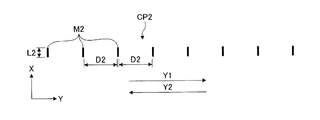
- ink is ejected from the ink ejection port 10 and ink droplets are landed at the backward landing position of the print medium W, thereby forming the check pattern CP2 shown in FIG. To do.
- Each of the check patterns CP1 and CP2 includes three linear marks M1 and M2 that are spaced apart in the main scanning direction and parallel to the sub-scanning direction.
- the length L1 in the sub-scanning direction of the mark M1 of the check pattern CP1 is longer than the length L2 in the sub-scanning direction of the mark M2 of the check pattern CP2, and the forward path and the backward path can be easily discriminated.
- the interval D1 between the marks M1 in the main scanning direction of the check pattern CP1 is wider than the interval D2 between the marks M2 in the main scanning direction of the check pattern CP2.
- the forward landing position is a position where ink droplets are landed on the printing surface of the print medium W by ejecting ink from the ink ejection port 10 while moving the head unit 11 in the forward direction Y1. That is, the forward landing position refers to a position where the mark M1 is formed on the printing surface of the print medium W.
- the return path landing position is a position where ink droplets are landed on the printing surface of the print medium W by discharging ink from the ink discharge port 10 while moving the head portion 11 in the return path direction Y2. That is, the return landing position refers to a position where the mark M2 is formed on the printing surface of the printing medium W.
- the center marks M1 and M2 overlap each other on the printing surface of the printing medium W as shown in FIG. Marks M2 at both ends of the check pattern CP2 are formed between the marks M1.
- the check patterns CP1 and CP2 shown in FIG. 10 indicate a case where these coincide with the optimum landing positions of the ink droplets determined in advance according to the desired gap G. That is, the check patterns CP1 and CP2 shown in FIG. 10 are shifted between the actual values of the forward landing position and the backward landing position and the optimal value that is the optimal landing position when the length of the gap G is an appropriate value. The case where no has occurred is shown.
- the check patterns CP1 and CP2 shown in FIG. 10 indicate the actual values of the forward landing positions and the return landing positions when the length of the gap G is an appropriate value, and the optimal values that are the optimal landing positions. ing. Note that the colors of the marks M1 and M2 may be different from each other or the same color. However, it is desirable that the marks M1 and M2 be easily distinguished from each other. *
- the check pattern CP1 includes a determination mark DM as information corresponding to each mark M1 and contributing to determining the degree of adjusting the length of the gap G in the gap adjustment process.
- the discrimination mark DM indicates whether the length of the gap G is an appropriate value, or longer or shorter than the appropriate value when the mark M2 of the check pattern CP2 overlaps the mark M1 of the corresponding check pattern CP1. Is.
- the discrimination mark DM is arranged at a position aligned with the mark M1 of the corresponding check pattern CP1 in the sub-scanning direction.
- the determination mark DM corresponding to the center mark M1 of the check pattern CP1 indicates that the length of the gap G is an appropriate value when the center mark M2 of the check pattern CP2 overlaps the center mark M1 of the check pattern CP1.
- the mark is “0.0 mm”.
- the determination mark DM corresponding to the left end of the check pattern CP1, that is, the mark M1 on the rear side of the forward direction Y1 is the mark M2 on the left end of the check pattern CP2, that is, the mark M2 on the front side in the return direction Y2 of the check pattern CP1.
- the determination mark DM corresponding to the right end of the check pattern CP1, that is, the front mark M1 in the forward direction Y1, is the right end of the check pattern CP2, that is, the rear mark M2 of the return direction Y2, to the right end mark M1 of the check pattern CP1. Is overlapped, it is marked “ ⁇ 0.1 mm” indicating that the length of the gap G is 0.1 mm shorter than an appropriate value.
- the print medium W is held on the holding portion 23a of the work set member 23 of the print medium holding portion 20, and the user places the thin film F on the printing surface of at least one print medium W. Affix it.
- the user inputs the rotation angle of the shaft member 22 of the rotation driving unit 24 from the input device 90 so that the printing surface to which the thin film F is attached is parallel to both the main scanning direction and the sub-scanning direction (step) ST1).
- the control device 60 rotates the shaft member 22 of the print medium holding unit 20 around the axis, and the printing surface to which the thin film F of the print medium W held by the holding unit 23a of the work set member 23 is attached. Are parallel to both the main scanning direction and the sub-scanning direction. *
- control device 60 moves the print medium holding unit 20 to the sub-scanning direction driving unit 50 and the gap driving unit 40 in the sub-scanning direction and the Z-axis direction, so that the holding unit for the work set member 23 of the printing medium holding unit 20
- the print medium W held by 23a and attached with the thin film F is moved below the housing 2, and the print medium W attached with at least the thin film F is detected by the laser sensor 70 (step ST2).
- the user determines the forward landing position and the backward landing position of the ink that forms the check patterns CP1 and CP2 in the main scanning direction and the sub scanning direction of the printing surface of the printing medium W on which the thin film F is pasted.
- Input from the input device 90 to the control device 60 step ST3. *
- the control device 60 sets the head unit 11 at a position appropriate for the forward landing position and the backward landing position input from the input device 90 to the sub-scanning direction driving unit 50, the gap driving unit 40, and the carriage driving unit 30. To position. At this time, the length of the gap G becomes a predetermined value between 1.0 mm and 1.5 mm.
- the control device 60 performs a discharge process for forming the check patterns CP1 and CP2 (step ST4). In the ejection process, ink is ejected from the ink ejection port 10 while reciprocating the carriage 12 at a constant speed in the main scanning direction, and is landed on the print medium W in the forward path and landed on the print medium W in the backward path. Ink droplets are landed at the return landing positions.
- the movement speeds of the carriage 12 in the forward path direction Y1 and the backward path direction Y2 are equal in the ejection process, and these movement speeds are constant.
- the control device 60 ejects ink from the ink ejection port 10 while moving the carriage 12 in the forward direction Y1 to form the check pattern CP1, and ejects ink while moving the carriage 12 in the backward direction Y2. Ink is ejected from the outlet 10 to form a check pattern CP2.
- the control device 60 causes ink droplets to land at three or more locations on the thin film F adhered to the printing surface, and the carriage
- the time interval at which the ink 12 is ejected while moving in the forward direction Y1 is different from the time interval at which ink is ejected while moving in the backward direction Y2.
- the time interval at which the carriage 12 ejects ink while moving in the forward direction Y1 is constant.
- the time interval at which the carriage 12 ejects ink while moving in the backward direction Y2 is constant, and is shorter than the time interval at which the carriage 12 ejects ink while moving in the forward direction Y1.
- the control device 60 forms the check pattern CP1 and writes the discrimination mark DM on the thin film F on the printing surface of the printing medium W.
- the check patterns CP1, CP2, that is, the forward landing position and the return path are applied to the thin film F attached to the printing surface of the print medium W.
- An actual measurement value based on the landing position is formed.
- the actual measurement values based on the forward landing position and the backward landing position refer to the marks M1 and M2 of the check patterns CP1 and CP2 formed on the printing surface of the printing medium W in the ejection process.
- the user determines whether there is an overlap between the mark M1 of the check pattern CP1 and the mark M2 of the check pattern CP2 (step ST5).
- step ST5 When the user determines that there is no overlap between the mark M1 of the check pattern CP1 and the mark M2 of the check pattern CP2 (step ST5: Yes), all the marks M2 of the check pattern CP2 are the check pattern CP1. It is determined whether or not the forward direction Y1 is ahead of all the marks M1 (step ST51). *
- step ST51 when the user determines that all the marks M2 of the check pattern CP2 are in front of the forward direction Y1 with respect to all the marks M1 of the check pattern CP1 (step ST51: Yes), the user inputs From the menu of the apparatus 90, “ ⁇ 0.2 mm” is selected to lower the print medium holding unit 20 by 0.2 mm in the Z-axis direction and away from the head unit 11 (step ST 52), and the control device 60 selects the print medium holding unit 20. Is lowered by 0.2 mm in the Z-axis direction (step ST53). *
- step ST51 determines that all marks M2 of the check pattern CP2 are not in front of the forward direction Y1 than all marks M1 of the check pattern CP1, that is, as shown in FIG. 14, all marks M2 of the check pattern CP2 are the check pattern CP1. If it is determined that it is behind the forward direction Y1 with respect to all the marks M1 (step ST51: No), the user raises the print medium holding part 20 by 0.2 mm in the Z-axis direction from the menu of the input device 90. “+0.2 mm” approaching the head unit 11 is selected (step ST54), and the control device 60 raises the print medium holding unit 20 by 0.2 mm in the Z-axis direction (step ST55). *
- control device 60 lowers the print medium holding unit 20 by 0.2 mm in the Z-axis direction (step ST53) or 0.2 mm (step ST55), and then uses the sub-scanning direction driving unit 50 and the carriage driving unit 30.
- the check patterns CP1 and CP2 are formed, the forward landing position and the backward landing position of the ink on the thin film F are shifted, or the user again designates the forward landing position and the backward landing position from the input device 90 (step ST56), the process returns to step ST4.
- steps ST4 to ST56 are repeated until any mark M1 of the check pattern CP1 and any mark M2 of the check pattern CP2 overlap.
- step ST5 When the user determines that there is an overlap between the mark M1 of the check pattern CP1 and the mark M2 of the check pattern CP2 (step ST5: No), the right end of the check pattern CP1, that is, the most forward direction Y1. It is determined whether or not the mark M2 at the right end of the check pattern CP2 overlaps the mark M1 on the front side (step ST61). As shown in FIG. 11, when the user determines that the mark M2 at the right end of the check pattern CP2 overlaps the mark M1 at the right end of the check pattern CP1 (step ST61: Yes), the printing medium is selected from the menu of the input device 90.
- ⁇ 0.1 mm is selected to lower the holding unit 20 by 0.1 mm in the Z-axis direction and move away from the head unit 11, and the control device 60 lowers the print medium holding unit 20 by 0.1 mm in the Z-axis direction ( Step ST62).
- step ST61 If the user determines that the mark M2 at the right end of the check pattern CP2 does not overlap the mark M1 at the right end of the check pattern CP1 (step ST61: No), the user marks the center mark M1 of the check pattern CP1 at the center of the check pattern CP2. It is determined whether or not the mark M2 overlaps (step ST63). As shown in FIG. 10, when the user determines that the center mark M2 of the check pattern CP2 overlaps the center mark M1 of the check pattern CP1 (step ST63: Yes), the print medium is selected from the menu of the input device 90. “0.0 mm” that maintains the position of the holding unit 20 in the Z-axis direction is selected, and the control device 60 maintains the position of the print medium holding unit 20 in the Z-axis direction (step ST64). *
- step ST63: No the leftmost mark M1 of the check pattern CP1, that is, the most forward direction Y1. It is determined whether or not the left end mark M2 of the check pattern CP2 overlaps the rear side (step ST65).
- step ST65: Yes the left end mark M1 of the check pattern CP2 overlaps the left end mark M1 of the check pattern CP1 (step ST65: Yes), as shown in FIG.
- “+0.1 mm” is selected to raise the holding unit 20 by 0.1 mm in the Z-axis direction and approach the head unit 11, and the control device 60 raises the print medium holding unit 20 by 0.1 mm in the Z-axis direction (step) ST66).
- steps ST5 to ST66 the actual measurement values of the ejection process shown in FIGS. 10 to 14 are compared with the optimum values shown in FIG. 10, and the actual measurement values are optimum based on the deviation in the main scanning direction.
- the gap driving unit 40 adjusts the length of the gap G so as to match the value or to approach the optimum value. Further, in the gap adjustment process, when step ST51 to step ST4 are repeated and step ST5 to step ST66 are performed to compare the actually measured value with the optimum value, the distance between the actually measured values, that is, between the marks M1 and M2.
- the degree for adjusting the length of the gap G that is, the lowering amount and the rising amount of the print medium holding unit 20 is determined.
- the optimum value based on the optimum landing position is such that the marks M1 and M2 overlap.
- the relative positional relationship between the marks M1 and M2 is determined in advance as the optimum value based on the optimum landing position. If it is, it is not necessary to overlap, and it can be arranged arbitrarily.
- the degree of separation and the direction of separation are not limited to the main scanning direction, and may be set in any direction including the sub-scanning direction. *
- the actual measurement value and the optimum value based on the forward landing position and the return landing position do not indicate only the separation distance in the main scanning direction.
- “ ⁇ 0.1 mm in the X direction and 0.3 mm in the Y direction” It can be applied to all numerical values shown on the coordinate axes in the XY direction.
- step ST61: No the control device 60 lowers the print medium holding unit 20 ( After step ST62), after maintaining the position of the print medium holding unit 20 (step ST64) and after raising the print medium holding unit 20 (step ST66), that is, after the gap adjustment process, the display of the inkjet printer 1
- the apparatus 80 displays the height in the Z-axis direction of the print medium holding unit 20 at which the length of the gap G is an appropriate value (step ST7).
- the control device 60 sets the print medium holding unit 20 to a height in the Z-axis direction where the length of the gap G is an appropriate value (step ST8).
- the length of the gap G is adjusted.
- the ink jet printer 1 ejects ink from the ink ejection port 10 while reciprocating the carriage 12 in the main scanning direction, and landed on the print medium W in the forward path, and the print medium W in the backward path. Ink droplets are landed on the print medium W at the return path landing positions where they land.
- the gap driving unit 40 Based on the check patterns CP1 and CP2 formed on the print medium W, the gap driving unit 40 adjusts the length of the gap G. *
- the gap adjustment method in the ejection process, ink is ejected each time the carriage 12 is moved in the forward direction Y1 and the backward direction Y2, and the optimum landing position determined in advance in the gap adjustment process is obtained.
- the gap driving unit 40 adjusts the length of the gap G based on the optimum value based on the marks M1 and M2 which are actually measured values based on the landing positions of the ink droplets formed in the ejection process. For this reason, the length of the gap G can be adjusted without using an expensive sensor such as a photosensor.
- the gap adjustment method can improve convenience even if the inkjet printer 1 has a simple configuration. That is, the gap adjustment method of the present embodiment can adjust the gap of the ink jet apparatus with a simple configuration, and can improve the convenience of the gap adjustment.
- the gap adjustment method of the present embodiment when adjusting the length of the gap G, the height of the print medium holding unit 20 in the Z-axis direction is adjusted. Accordingly, it is possible to cope with frequent changes in the shape and thickness of the print medium W without changing the position on the ink discharge port 10 side, and the convenience as the inkjet printer 1 can be further enhanced.
- the gap adjustment method of the present embodiment when the carriage 12 is moved in the forward direction Y1 and the backward direction Y2, ink droplets are landed at three or more places, and the marks M1 and M2 are placed at three or more places on the thin film F. Form. For this reason, according to the gap adjustment method of the present embodiment, it is possible to clearly discriminate the deviation between the actual values of the forward landing position and the backward landing position in the backward direction Y1 and the backward direction Y2. Further, since the deviation is grasped based on the actually measured values of the three or more forward landing positions and the return landing positions, it is possible to grasp the direction of the deviation and the position with little deviation. *
- the gap adjusting method of the present embodiment since the moving speed of the carriage 12 when ejecting ink from the ink ejection port 10 is constant, the length of the gap G that is an optimum value based on the optimum landing position can be easily achieved. I can grasp. In addition, the difference between the mark M1 indicating the actual measurement value based on the forward landing position in the forward direction Y1 and the mark M2 indicating the actual measurement value based on the return landing position in the backward direction Y2 is constant, and thus the discrimination is easy. Can do. *
- the degree of adjusting the length of the gap G is determined by the mark M1 of the check pattern CP1 formed in the forward direction Y1 and the mark M2 of the check pattern CP2 formed in the backward direction Y2. Based on and. Therefore, according to the gap adjustment method of the present embodiment, the degree of adjustment of the length of the gap G can be determined by landing the ink while moving the carriage 12 in the forward direction Y1 and the backward direction Y2 once. Therefore, the size of the gap G can be adjusted simply and quickly.
- the movement of the carriage 12 in the forward direction Y1 and the backward direction Y2 is not limited to one degree, and one or both may be performed a plurality of times.
- the check pattern CP1 is created on the forward path or the backward path, and then scanning and ejection are repeated several times on the backward path or the forward path.
- the check pattern CP2 can be created.
- the discrimination mark DM is also entered when the check patterns CP1 and CP2 are formed. Therefore, the degree of adjustment of the length of the gap G can be determined easily and quickly, and convenience is improved. can do.
- the gap adjustment method of the present embodiment since the ejection process is performed on the thin film F that is releasably attached to the print medium W, the check patterns CP1 and CP2 are formed on the print medium W that the inkjet printer 1 actually prints. can do. For this reason, this gap adjustment method can adjust the length of the gap G by actually landing the ink on the print medium W, so that the gap is not affected by the variation in the dimensions of the print medium W, so The length of the gap G can be adjusted. Further, since the peelable thin film F is used, the length of the gap G can be adjusted without soiling the print medium W. *
- the interval at which ink is ejected is constant in each of the forward path and the backward path, so the degree of adjusting the length of the gap G can be easily and quickly determined based on the ink landing position. can do.
- the length of the gap G is adjusted by the above-described gap adjusting method. Therefore, the length of the gap G can be adjusted with a simple configuration, and the length of the gap G is adjusted. Convenience can be improved. *
- the ink jet printer 1 can determine the forward landing position and the return landing position of the ink on the print medium W, and is appropriate for the forward landing position and the return landing position.
- the ink discharge port 10 can be positioned at the position. Therefore, the ink jet printer 1 can reliably form the check patterns CP1 and CP2 at predetermined positions on the print medium W.
- the position determining means provided in the input device 90 determines the forward landing position and the backward landing position based on the appropriate gap G, the print medium W is within the limited range shown in FIG. Can be reliably printed, and can be applied to a print medium in which margins are hardly allowed. *
- FIG. 15 is a diagram illustrating a check pattern during a forward path of a gap adjustment method for an inkjet apparatus according to a modification of the embodiment.
- FIG. 16 is a diagram illustrating a check pattern at the time of a return pass in the gap adjustment method for the ink jet device according to the modification of the embodiment.
- FIG. 17 is a diagram illustrating an example of a check pattern formed on a printing surface of a printing medium in a gap adjustment method for an inkjet device according to a modification of the embodiment.
- the same parts as those in the embodiment are denoted by the same reference numerals and the description thereof is omitted. *
- the check patterns CP1 and CP2 are separated in the main scanning direction and sub-scanned as shown in FIGS. A large number of linear marks M1 and M2 parallel to the direction are provided. Further, the discrimination mark DM corresponding to each mark M1 of the check pattern CP1 indicates an appropriate value of the length of the gap G. That is, the discrimination mark DM corresponding to each mark M1 of the check pattern CP1 indicates an appropriate value of the length of the gap G when the mark M2 overlaps the mark M1 or is arranged in the sub-scanning direction. For example, when the mark M2 overlaps the mark M1 that is “ab” or is arranged in the sub-scanning direction, the discrimination mark DM has an appropriate value for the length of the gap G. bmm. *
- the gap adjusting method forms check patterns CP1 and CP2 on the thin film F attached to the printing surface of the print medium W, and then the user checks these check patterns CP1.
- CP2 marks M1 and M2 with the smallest deviation in the main scanning direction, that is, marks M1 and M2 arranged in the sub-scanning direction are extracted.
- the discrimination mark DM corresponding to the mark M1 extracted by the user is read, the read value is input from the input device 90, and the control device 60 sets the length of the gap G to the value input from the input device 90.
- the discrimination mark DM corresponding to the mark M1 among the marks M1 and M2 arranged in the sub-scanning direction is “ac”. Therefore, in the example shown in FIG. 17, the user inputs “ac” from the input device 90, and the control device 60 sets the length of the gap G to a. Adjust to cmm. *
- the gap adjustment method according to the modification of the embodiment ejects ink each time the carriage 12 is moved in the forward direction Y1 and the backward direction Y2, and the forward landing position of the ink droplet in the gap adjustment step
- the length of the gap G is adjusted based on the actual measurement value based on the return landing position. Therefore, the gap adjustment method can make the inkjet printer 1 a simple configuration and improve the convenience as in the embodiment.
- the gap adjusting method according to the modified example extracts marks M1 and M2 arranged in the sub-scanning direction from the check patterns CP1 and CP2 formed on the printing surface of the print medium W, and corresponds to the mark M1 extracted by the user. By inputting the value indicated by the discrimination mark DM from the input device 90, the length of the gap G can be adjusted to an appropriate value. Therefore, the gap adjustment method according to the modification can quickly adjust the length of the gap G to an appropriate value.
- the check patterns CP1 and CP2 are formed on the print medium W on which the inkjet printer 1 actually prints.
- the check patterns CP ⁇ b> 1 and CP ⁇ b> 2 may be formed on the landing target having the same shape as the print medium W in addition to the print medium W actually printed by the inkjet printer 1.
- the check patterns CP1 and CP2 are formed on one print surface of the print medium W.
- the check patterns CP1 and CP1 are formed on each print surface of the print medium W. It is desirable to form CP2 and adjust the length of the gap G for each printing surface.
- the check patterns CP1 and CP2 include three or more marks M1 and M2.
- at least one mark M1 that is a landing position in each of the forward path and the backward path. M2 may be formed.
- a gap to be adjusted may be set by comparing the position of the mark M2 with respect to the mark M1.
- a film is affixed to the workpiece and printed on the film.
- the gap adjusting method according to the present invention it is possible to estimate the thickness of the film with high accuracy using the gap width between the optimum landing position and the case where the film is applied.
Landscapes
- Engineering & Computer Science (AREA)
- Manufacturing & Machinery (AREA)
- Quality & Reliability (AREA)
- Ink Jet (AREA)
- Common Mechanisms (AREA)
- Accessory Devices And Overall Control Thereof (AREA)
Abstract
簡便な構成でかつ利便性を向上することができるインクジェット装置のギャップ調整方法及びインクジェット装置を提供すること。 インクジェット装置のギャップ調整方法は、インクが吐出されるインク吐出口を有するヘッド部と、ヘッド部が設けられ主走査方向に移動するキャリッジと、インク吐出口とギャップをおいて設けられる印刷媒体と、ギャップの長さを調整するギャップ駆動部とを備える。ギャップ調整方法は、吐出工程(ステップST4)とギャップ調整工程(ステップST5~ステップST56)を含む。吐出工程(ステップST4)は、キャリッジを主走査方向に往復移動させながら往路、復路各々でインクを吐出する。ギャップ調整工程は、往路着弾位置及び復路着弾位置と予め決定された最適着弾位置とを比較し、ギャップ駆動部によりギャップの長さを調整する。
Description
本発明は、インク吐出口と着弾対象物とのギャップの長さを調整するインクジェット装置のギャップ調整方法及びインクジェット装置に関するものである。
キャリッジを主走査方向に移動させつつインク滴を自然落下させるインクジェットプリンタなどのインクジェット装置において、適切な位置に着弾を図るには、インク吐出口と着弾対象物とのギャップを適切な距離に調整することが不可欠である。しかしながら、ギャップの長さを調整する際に、0.1mm以下の精度の調整が要求される場合、スケール等を用いた目視での調整は、極めて困難となる。このように、0.1mm以下の精度が要求される調整方法が、特許文献1及び特許文献2に提案されている。
特許文献1には、フォトセンサによりギャップを測定して、測定結果に応じて、ギャップの長さを調整する方法が開示されている。特許文献2には、着弾位置のズレとギャップとの間隔を示す検量線を作成し、検量線に応じてインク吐出口の位置ズレ距離を検知するインクジェットヘッドの検査方法が開示されている。
しかしながら、特許文献1に示された方法でギャップを測定するのでは、フォトセンサなどの高価で複雑な機構が必要となり、また、信頼性の確保も難しい。また、特許文献2に示された方法では、環境の変化などに応じて検量線を作成しなおす必要が生じ、利便性に乏しい。
本発明は、上記に鑑みてなされたものであって、インクジェット装置を簡便な構成としても利便性を向上することができるインクジェット装置のギャップ調整方法及びインクジェット装置を提供することを目的とする。
上述した課題を解決し、目的を達成するために、本発明に係るインクジェット装置のギャップ調整方法は、インクが吐出されるインク吐出口を有するヘッド部と、前記ヘッド部が設けられ、主走査方向に移動するキャリッジと、前記インク吐出口とギャップをおいて設けられる着弾対象物と、前記ギャップの長さを調整するギャップ調整手段と、を備えたインクジェット装置のギャップ調整方法であって、前記キャリッジを前記主走査方向に往復移動させながら前記インク吐出口からインクを吐出し、前記キャリッジの往路においてインク滴を着弾させる前記着弾対象物上の位置である往路着弾位置と、前記キャリッジの復路においてインク滴を着弾させる前記着弾対象物上の位置である復路着弾位置と、に各々インク滴を着弾させる吐出工程と、前記吐出工程において実際にインク滴が着弾した前記往路着弾位置及び前記復路着弾位置に基づく実測値と、所望のギャップに応じて予め決定された前記往路着弾位置及び前記復路着弾位置のそれぞれの最適着弾位置に基づく最適値とを比較し、前記実測値と前記最適値とのズレに基づいて、前記ギャップ調整手段により前記ギャップの長さを調整するギャップ調整工程と、を含むことを特徴とする。
この発明では、吐出工程において往路復路各々でインクを吐出し、ギャップ調整工程において、予め決定された最適着弾位置に基づく最適値と、吐出工程により形成した着弾位置に基づく実測値とに基づいて、ギャップ調整手段によりギャップの長さを調整する。このため、フォトセンサなどの高価なセンサを用いることなく、ギャップの長さを調整することができる。また、予め決定された最適着弾位置に基づく最適値と、吐出工程により形成した着弾位置に基づく実測値とに基づいて、ギャップ調整手段によりギャップの長さを調整するので、環境の変化などに応じて検量線を作成しなおす必要がなくなり利便性を向上することができる。よって、本発明に係るインクジェット装置のギャップ調整方法においては、インクジェット装置を簡便な構成としても利便性を向上することができる。
また、上記インクジェット装置のギャップ調整方法において、前記ギャップの長さの調整は、前記往路着弾位置及び前記復路着弾位置の前記実測値の離間の距離、及び/又は主走査方向における互いの位置関係に基づいて行われることが好ましい。
この発明では、ギャップの長さを調整する度合いを往路着弾位置と復路着弾位置に基づく実測値で判別するので、キャリッジを往路、復路で少なくとも1度ずつ移動させながらインクを着弾させることで、ギャップの長さを調整する度合いを判別できる。したがって、この発明は、インクジェット装置を簡便な構成にしても迅速にギャップの長さの調整を行うことができる。
また、上記インクジェット装置のギャップ調整方法において、前記吐出工程において、前記往路、復路各々で三か所以上に前記インク滴を着弾させるとともに、前記往路のインクを吐出する間隔と、前記復路のインクを吐出する間隔とを異ならせることが好ましい。
この発明では、三か所以上の往路着弾位置及び復路着弾位置に基づく実測値が形成されるので、往路着弾位置及び復路着弾位置に基づく実測値間のズレを明確に判別することができる。また、三か所以上の往路着弾位置及び復路着弾位置に基づく実測値に基づいてズレを把握するので、ズレの方向やズレの少ない位置などを把握することができる。
また、上記インクジェット装置のギャップ調整方法において、前記吐出工程において、前記インク吐出口から前記インクを吐出する際の前記キャリッジの移動速度が一定であることが好ましい。
この発明では、キャリッジの移動速度が一定であるので、最適着弾位置に基づく最適値となるギャップを容易に把握できる。また、往路着弾位置及び復路着弾位置に基づく実測値のズレ幅が一定となり、判別を容易に行うことができる。
また、上記インクジェット装置のギャップ調整方法において、前記吐出工程において、前記ギャップ調整工程で前記ギャップの長さを調整する度合いを判別するに寄与する情報を前記着弾対象物に記入することが好ましい。
この発明では、判別に寄与する情報によりギャップ調整工程のギャップの長さを調整する度合いを、インクジェット装置を簡便な構成にしても迅速に判断でき、利便性を向上することができる。
また、上記インクジェット装置のギャップ調整方法において、前記吐出工程において、前記インクを前記着弾対象物に剥離可能に貼付した薄膜に着弾させることが好ましい。
この発明では、着弾対象物に剥離可能に貼付された薄膜に吐出工程が行われるので、着弾対象物を、インクジェット装置が印刷する印刷媒体とすることができる。このため、この発明では、印刷媒体に対してインクを実際に着弾させてギャップの長さの調整を行うことができるので、印刷媒体の寸法のばらつきに影響させず、確実に、ギャップの長さの調整を行うことができる。また、剥離可能な薄膜を用いるので、印刷媒体を汚すことなく、ギャップの長さを調整することができる。
また、上記インクジェット装置のギャップ調整方法において、前記吐出工程において、前記往路の三か所以上に前記インク滴を着弾させるインクを吐出する間隔は、一定であり、前記復路の三か所以上に前記インク滴を着弾させるインクを吐出する間隔は、一定であることが好ましい。
この発明では、往路、復路各々におけるインクを吐出する間隔が一定であるので、インクを吐出して形成された着弾位置に基づく実測値に基づいて、ギャップの長さを調整する度合いをインクジェット装置を簡便な構成としても迅速に判断することができる。
上述した課題を解決し、目的を達成するために、本発明に係るインクジェット装置は、インクが吐出されるインク吐出口を有するヘッド部と、前記ヘッド部が設けられ、主走査方向に移動するキャリッジと、前記インク吐出口とギャップをおいて設けられる着弾対象物と、前記ギャップの長さを調整するギャップ調整手段と、を備えたインクジェット装置であって、前記キャリッジを前記主走査方向に往復移動させながら前記インク吐出口からインクを吐出し、前記キャリッジの往路においてインク滴を着弾させる前記着弾対象物上の位置である往路着弾位置と、前記キャリッジの復路においてインク滴を着弾させる前記着弾対象物上の位置である復路着弾位置と、に各々インク滴を着弾させることで前記着弾対象物にチェックパターンを形成し、該チェックパターンに基づいて前記ギャップ調整手段により前記ギャップの長さが調整されることを特徴とする。
この発明では、往路復路各々でインクを吐出して形成された着弾位置に基づく実測値に基づいて、ギャップ調整手段によりギャップの長さが調整されている。このため、フォトセンサなどの高価なセンサを用いることなく、ギャップの長さを調整することができる。また、チェックパターンに基づいて、ギャップ調整手段によりギャップの長さを調整するので、環境の変化などに応じて検量線を作成しなおす必要がなくなり利便性を向上することができる。よって、インクジェット装置は、簡便な構成でかつ利便性を向上することができる。
また、上記インクジェット装置において、前記チェックパターンを形成する際に、前記主走査方向と前記主走査方向に直交する副走査方向における前記着弾対象物の前記往路着弾位置及び前記復路着弾位置を定める位置決定手段と、前記往路着弾位置及び前記復路着弾位置に対して適切な位置に前記インク吐出口を位置付けるヘッド位置調整手段と、を備えることが好ましい。
この発明では、チェックパターンを形成する際に、着弾対象物へのインクの往路着弾位置及び復路着弾位置を定めることができ、往路着弾位置及び前記復路着弾位置に対して適切な位置にインク吐出口を位置付けることができる。よって、インクジェット装置は、着弾対象物の所定の位置にチェックパターンを確実に形成することができる。
本発明によれば、インクジェット装置のギャップ調整を簡便な構成でかつ利便性を向上させて行うことができる。
以下に、本発明に係るインクジェット装置のギャップ調整方法及びインクジェット装置の実施形態を図面に基づいて詳細に説明する。なお、この実施形態によりこの発明が限定されるものではない。また、下記実施形態における構成要素には、当業者が置換可能、且つ、容易なもの、或いは実質的に同一のものが含まれる。
〔実施形態〕 図1は、実施形態にかかるインクジェット装置のギャップ調整方法によりギャップの長さが調整されるインクジェットプリンタの概略構成を示す図である。図2は、実施形態にかかるインクジェット装置のギャップ調整方法によりギャップの長さが調整されるインクジェットプリンタの概略構成を示す斜視図である。図3は、図2に示されたインクジェットプリンタの印刷媒体保持部及びギャップ駆動部を示す斜視図である。図4は、図2に示されたインクジェットプリンタの印刷媒体保持部を示す斜視図である。図5は、図2に示されたインクジェットプリンタの概略の構成を示すブロック図である。
インクジェット装置の一例としての図1~図3に示すインクジェットプリンタ1は、図2に示すインク容器101から供給されたインクを吐出するインク吐出口10を複数備えたヘッド部11をY軸方向と平行な主走査方向に往復移動させ、インク吐出口10から図3に示す着弾対象物である印刷媒体Wにインクを吐出することで、印刷媒体Wを印刷するものである。インクジェットプリンタ1は、印刷媒体Wにインクジェット方式で印刷を行う装置である。印刷媒体Wは、立体物であり、例えば、本実施形態では、スマートフォンなどの携帯端末のカバーである。携帯端末のカバーである印刷媒体Wは、第1の被印刷面と、この第1の被印刷面に対する側面である第2の被印刷面などの被印刷面を複数有する立体物である。
インクジェットプリンタ1は、図1~図3、図5に示すように、ヘッド部11と、キャリッジ12と、複数の印刷媒体Wを保持する印刷媒体保持部20と、キャリッジ駆動部30と、ギャップ調整手段に相当するギャップ駆動部40と、副走査方向駆動部50と、制御装置60を備える。
ヘッド部11は、インクが吐出されるインク吐出口10を複数有する。ヘッド部11は、複数のインク吐出口10がインク容器101に貯留されたM(マゼンタ)、C(シアン)、Y(イエロー)、K(ブラック)のいずれかの色のインクを吐出することができるように設けられている。ヘッド部11は、印刷する内容に応じた色のインクをインク吐出口10から吐出する。なお、ヘッド部11から吐出する色の組み合わせは、これ以外のものでもよい。ヘッド部11のインク吐出口10は、例えば、印刷媒体Wに対向してインクを吐出するプリンタヘッド、インク容器101とプリンタヘッドとを接続する各種インク流路、インク流路上に設けられるレギュレータ及びポンプ等を含んで構成される。なお、本実施形態では、ヘッド部11は、紫外線が照射されて露光することで硬化度が変化するインクを吐出する。
キャリッジ12は、ヘッド部11が設けられ、直線状のYバー13に沿って主走査方向に往復移動するものである。キャリッジ12は、インクを吐出するヘッド部11と紫外線を照射する紫外線照射器14を主走査方向に移動させながら印刷媒体Wの被印刷面を印刷するものである。キャリッジ12は、Yバー13に沿って主走査方向に移動制御される。また、キャリッジ12は、ヘッド部11と、ヘッド部11の主走査方向の両側に設けた露光部としての一対の紫外線照射器14とを有している。各紫外線照射器14は、印刷媒体Wに吐出されたインクに対して露光可能なものである。各紫外線照射器14は、例えば、紫外線を照射可能なLEDモジュール等により構成される。
図3に示された印刷媒体保持部20は、被印刷面をヘッド部11と対向させて、複数の印刷媒体Wを保持するものである。印刷媒体保持部20は、図4に示すように、筐体部21と、複数の軸部材22と、複数のワークセット部材23と、回転駆動部24などを有する。
筐体部21は、印刷媒体保持部20の筐体部分である。本実施形態において、筐体部21は、印刷時にヘッド部11と対向する側が開放された箱状体であり、主走査方向に対向する2つの側面によりそれぞれの軸部材22の一端及び他端を支持することにより、それぞれの軸部材22を回転可能に保持する。また、これにより、筐体部21は、軸保持部として機能する。
複数の軸部材22は、印刷媒体Wの被印刷面をヘッド部11と対向させるために、印刷媒体Wを回転させる駆動シャフトである。本例において、それぞれの軸部材22は、主走査方向と平行に配置され、筐体部21に軸心回りに回転自在に支持される。
複数のワークセット部材23は、それぞれ、印刷可能な所定の位置に印刷媒体Wを設置するためのものである。ワークセット部材23は、いずれかの軸部材22を貫通させた状態で軸部材22に対して固定されており、軸部材22に対して印刷媒体Wを固定する。また、これにより、ワークセット部材23は、軸部材22の回転に応じて、印刷媒体Wを軸部材22と共に回転させる。
ワークセット部材23は、軸部材22を中心として互いに反対側の位置に印刷媒体Wを保持する保持部23aを備える。即ち、ワークセット部材23は、保持部23aを一対備える。また、ワークセット部材23は、各軸部材22の長手方向に二つ設けられている。即ち、各軸部材22は、二つのワークセット部材23を貫通する。そのため、本実施形態によれば、多数の印刷媒体Wを同時に印刷媒体保持部20で保持することができる。
回転駆動部24は、複数の軸部材22を回転させる駆動部である。本実施形態において、回転駆動部24は、複数のプーリ、ステッピングモータ、及びタイミングベルトを有して、それぞれの軸部材22を軸心回りに回転させる。回転駆動部24は、制御装置60と電気的に接続され、制御装置60によってその駆動が制御される。
前述した構成の印刷媒体保持部20は、インク吐出口10と図1に示すギャップGをおいて複数の印刷媒体Wを保持する。即ち、インクジェットプリンタ1は、インク吐出口10とギャップGをおいて設けられる印刷媒体Wを複数備える。
キャリッジ駆動部30は、Yバー13に対してキャリッジ12即ちヘッド部11及び紫外線照射器14を主走査方向に相対的に往復移動させる駆動装置である。キャリッジ駆動部30は、例えば、キャリッジ12に連結された搬送ベルト等の伝動機構、搬送ベルトを駆動するモータ等の駆動源を含んで構成され、駆動源が発生させた動力を伝達機構を介してキャリッジ12を主走査方向に沿って往復移動させる動力に変換し、キャリッジ12を主走査方向に沿って往復移動させる。キャリッジ駆動部30は、制御装置60と電気的に接続され、制御装置60によってその駆動が制御される。なお、本実施形態では、キャリッジ12、Yバー13、キャリッジ駆動部30は、図2に示す筐体2内に収容される。
ギャップ駆動部40は、筐体2即ちヘッド部11に対して印刷媒体保持部20即ち印刷媒体Wをヘッド部11のインクの吐出方向に沿って移動させるものである。なお、本実施形態のインクの吐出方向は鉛直方向ともいい、Z軸方向と平行な方向である。また、インクの吐出方向とは、ヘッド部11がインクを吐出する方向である。これにより、ギャップ駆動部40は、ヘッド部11のインク吐出口10と印刷媒体Wの被印刷面との間のギャップGの長さを調整する。ギャップ駆動部40は、例えば、Z軸方向の5cm程度の範囲で、印刷媒体保持部20を動かす。また、本発明では、ギャップGの長さの調整は、例えば、ヘッド部11をインクの吐出方向に沿って移動させることで行ってもよい。この場合、ギャップ駆動部40は、例えば、Yバー13を移動させることにより、ヘッド部11に対して相対的に印刷媒体保持部20を移動させる。なお、本実施形態では、ギャップ駆動部40は、筐体2を支持するベース3上に設置され、ベース3と印刷媒体保持部20との間に配置されている。
副走査方向駆動部50は、筐体2即ちヘッド部11に対して印刷媒体保持部20即ち印刷媒体Wを主走査方向に対して直交するX軸方向と平行な副走査方向に移動させるものである。また、本発明では、ヘッド部11を副走査方向に移動させてもよい。なお、本実施形態では、副走査方向駆動部50は、ベース3上に設置されて、ベース3と印刷媒体保持部20との間に配置されている。
なお、キャリッジ駆動部30、ギャップ駆動部40及び副走査方向駆動部50は、後述する図8及び図9に示すチェックパターンCP1,CP2を形成する際に、インクの後述する往路着弾位置及び復路着弾位置に対して適切な位置にインク吐出口10を位置付けるヘッド位置調整手段に相当する。
また、インクジェットプリンタ1は、図5に示すように、レーザーセンサ70と、ポテンショメータ71,72,73と、各種の情報を表示する表示装置80と、入力装置90とを備える。レーザーセンサ70は、例えば、筐体2内に収容され、かつヘッド部11などに取り付けられて、印刷媒体WとのギャップGを検出し、検出結果を制御装置60に出力する。ポテンショメータ71は、Yバー13に対するキャリッジ12の主走査方向の位置を検出し、検出結果を制御装置60に出力する。ポテンショメータ72は、ベース3に対する印刷媒体保持部20のZ軸方向の位置、即ち、ギャップGに応じた情報を検出し、検出結果を制御装置60に出力する。ポテンショメータ73は、ベース3に対する印刷媒体保持部20の副走査方向の位置を検出し、検出結果を制御装置60に出力する。
制御装置60は、ヘッド部11、各紫外線照射器14等を含むインクジェットプリンタ1の各部を制御するものである。制御装置60は、機能概念的に、吐出制御部60a、露光制御部60b、パターン変換部60c等を含んで構成されている。また、制御装置60は、演算装置、メモリ等のハードウェア及びこれらの所定の機能を実現させるプログラムから構成されている。
制御装置60が有する吐出制御部60aは、ヘッド部11の各インク吐出口10のポンプ等を制御し、インク吐出口10から吐出するインクの吐出量、吐出タイミング、吐出期間等を制御するものである。露光制御部60bは、各紫外線照射器14等を制御し、当該各紫外線照射器14から照射する紫外線の強度、露光タイミング、露光期間等を制御するものである。パターン変換部60cは、制御装置60に有線/無線で接続されるPC、種々の端末等の入力装置90から入力される入力情報に応じて、吐出制御量や露光制御量を設定するものである。
パターン変換部60cには、入力情報として、例えば、入力装置90等を介して入力された画像情報であって、印刷媒体Wの被印刷面に印刷したい所定の図形等の画像情報等が入力される。パターン変換部60cは、この入力情報に基づいて、印刷媒体Wの被印刷面に印刷したい所
定の図形となる印刷パターンを生成し、当該生成した印刷パターンを実現可能な吐出制御量、露光制御量に変換する。そして、吐出制御部60aは、パターン変換部60cが算出した吐出制御量に基づいてヘッド部11のインク吐出口10による吐出を制御し、露光制御部60bは、パターン変換部60cが算出した露光制御量に基づいて各紫外線照射器14による露光を制御する。
定の図形となる印刷パターンを生成し、当該生成した印刷パターンを実現可能な吐出制御量、露光制御量に変換する。そして、吐出制御部60aは、パターン変換部60cが算出した吐出制御量に基づいてヘッド部11のインク吐出口10による吐出を制御し、露光制御部60bは、パターン変換部60cが算出した露光制御量に基づいて各紫外線照射器14による露光を制御する。
また、制御装置60は、ギャップGの長さの調整時に印刷媒体Wの被印刷面に印刷する図8及び図9に示すチェックパターンCP1,CP2を記憶している。チェックパターンCP1,CP2は、ギャップGの長さを調整する際に印刷媒体Wの被印刷面に印刷されるものである。制御装置60は、入力装置90から印刷媒体WのチェックパターンCP1,CP2を印刷する位置が指定される。このように、入力装置90は、チェックパターンCP1,CP2を形成する際に、主走査方向と副走査方向の印刷媒体Wへのインクの往路着弾位置及び復路着弾位置を定める位置決定手段をなしている。
これらのように構成されるインクジェットプリンタ1は、ギャップGの長さを例えば1.0mm~1.5mmの範囲の適切な値に調整した後、制御装置60による制御に応じて、印刷媒体Wに対してキャリッジ12を主走査方向に往復移動させつつ、印刷媒体Wの被印刷面に対してヘッド部11からインク滴を吐出する。そして、インクジェットプリンタ1は、制御装置60による制御に応じて、各紫外線照射器14が所定のタイミングで、紫外線を照射し露光することで印刷媒体Wに着弾したインクを硬化させる。そして、インクジェットプリンタ1は、印刷媒体Wを副走査方向に移動させた後、キャリッジ12を主走査方向に往復移動させつつ、印刷媒体Wの被印刷面に対してヘッド部11からインク滴を吐出する。インクジェットプリンタ1は、これらを繰り返し、所定の図形を印刷媒体Wの被印刷面に印刷していく。
この間、制御装置60は、吐出制御部60aがヘッド部11の各インク吐出口10から吐出するインクの吐出量、吐出タイミング、吐出期間等を制御し、露光制御部60bが各紫外線照射器14から照射する紫外線の強度等を制御する。これにより、インクジェットプリンタ1は、パターン変換部60cが生成した印刷パターンに応じて、印刷媒体Wの被印刷面に所定の図形を印刷することができる。
次に、本実施形態に係るインクジェット装置のギャップ調整方法を図面に基づいて説明する。なお、図6は、実施形態に係るインクジェット装置のギャップ調整方法の一例を示すフローの一部を示す図である。図7は、実施形態に係るインクジェット装置のギャップ調整方法の一例を示すフローの残りを示す図である。図8は、実施形態に係るインクジェット装置のギャップ調整方法の往路時のチェックパターンを示す図である。図9は、実施形態に係るインクジェット装置のギャップ調整方法の復路時のチェックパターンを示す図である。図10は、実施形態に係るインクジェット装置のギャップ調整方法のギャップが適切な値である場合の往路、復路のチェックパターンを示す図である。図11は、実施形態に係るインクジェット装置のギャップ調整方法のギャップが適切な値よりも0.1mm短い場合の往路、復路のチェックパターンを示す図である。図12は、実施形態に係るインクジェット装置のギャップ調整方法のギャップが適切な値よりも0.1mm長い場合の往路、復路のチェックパターンを示す図である。図13は、実施形態に係るインクジェット装置のギャップ調整方法のギャップが適切な値よりも0.2mm短い場合の往路、復路のチェックパターンを示す図である。図14は、実施形態に係るインクジェット装置のギャップ調整方法のギャップが適切な値よりも0.2mm長い場合の往路、復路のチェックパターンを示す図である。
本実施形態に係るインクジェット装置のギャップ調整方法(以下、単にギャップ調整方法と記す)は、ヘッド部11のインク吐出口10と印刷媒体保持部20に保持された印刷媒体Wの被印刷面との間のギャップGの長さ、つまりギャップGの距離を、適切な値に調整する方法である。なお、ギャップGの長さの適切な値とは、ヘッド部11の主走査方向のうちの一方向であり、図8などに矢印Y1で示される往路方向に移動させてインクを吐出して形成する画像と、他方向であり、図9などに矢印Y2で示される復路方向に移動させてインクを吐出して形成する画像とにより、印刷媒体Wの被印刷面に、入力された画像情報に応じた所定の図形を印刷することができる距離をいう。即ち、ギャップGの長さの適切な値とは、往路方向Y1に移動するヘッド部11のインク吐出口10から吐出するインクと、復路方向Y2に移動するヘッド部11のインク吐出口10から吐出するインクとを同じ位置に着弾させたい場合、往路方向Y1に移動するヘッド部11のインク吐出口10から吐出するインクと、復路方向Y2に移動するヘッド部11のインク吐出口10から吐出するインクとを同じ位置に着弾できる値をいう。
本実施形態に係るギャップ調整方法では、図3に示されるように、印刷媒体保持部20に保持された複数の印刷媒体Wのうち少なくとも一つの印刷媒体Wの被印刷面に剥離可能に貼付した薄膜Fに、ヘッド部11のインク吐出口10から吐出してインク滴を着弾させて、図10~図14のいずれかに示すチェックパターンCP1,CP2を形成する。なお、薄膜Fは、例えば、合成樹脂から構成され、厚さが0.1mm未満であるとともに、印刷媒体Wの被印刷面に貼付される粘着層が形成されたものが用いられる。尚、薄膜Fの厚さ分については、予め決定される最適着弾位置に厚さ分の補正を加えておくことが好ましい。
本実施形態に係るギャップ調整方法では、ヘッド部11を往路方向Y1に移動させながらインク吐出口10からインクを吐出させて印刷媒体Wの往路着弾位置にインク滴を着弾させて、図8に示すチェックパターンCP1を形成する。ギャップ調整方法では、ヘッド部11を復路方向Y2に移動させながらインク吐出口10からインクを吐出させて印刷媒体Wの復路着弾位置にインク滴を着弾させて、図9に示すチェックパターンCP2を形成する。チェックパターンCP1,CP2は、主走査方向に離間しかつ副走査方向と平行な直線状の印M1,M2をそれぞれ三つ備える。チェックパターンCP1の印M1の副走査方向の長さL1は、チェックパターンCP2の印M2の副走査方向の長さL2よりも長く、往路分と復路分とが容易に判別可能とされている。またチェックパターンCP1の主走査方向の印M1間の間隔D1は、チェックパターンCP2の主走査方向の印M2間の間隔D2よりも広い。
なお、往路着弾位置とは、ヘッド部11を往路方向Y1に移動させながらインク吐出口10からインクを吐出させて印刷媒体Wの被印刷面上にインク滴が着弾される位置をいう。即ち、往路着弾位置とは、印刷媒体Wの被印刷面上に印M1が形成される位置をいう。また、復路着弾位置とは、ヘッド部11を復路方向Y2に移動させながらインク吐出口10からインクを吐出させて印刷媒体Wの被印刷面上にインク滴が着弾される位置をいう。即ち、復路着弾位置とは、印刷媒体Wの被印刷面上に印M2が形成される位置をいう。
本実施形態では、ギャップGの長さが適切な値であると、印刷媒体Wの被印刷面には、図10に示すように、中央の印M1,M2同士が重なり、チェックパターンCP1の両端の印M1間に、チェックパターンCP2の両端の印M2が形成される。図10に示されたチェックパターンCP1,CP2は、これらが、所望のギャップGに応じて予め決定されたインク滴の最適着弾位置と一致している場合を示している。即ち、図10に示されたチェックパターンCP1,CP2は、往路着弾位置及び復路着弾位置の実測値と、ギャップGの長さが適切な値であるときの最適着弾位置である最適値とにズレが生じていない場合を示している。このように、図10に示されたチェックパターンCP1,CP2は、ギャップGの長さが適切な値であるときの往路着弾位置及び復路着弾位置の実測値及び最適着弾位置である最適値を示している。なお、印M1,M2の色は、互いに異なってもよく、同じ色でもよいが、望ましくは、印M1,M2同士の識別が容易な色であるのが望ましい。
また、チェックパターンCP1は、各印M1に対応し、かつギャップ調整工程のギャップGの長さを調整する度合いを判別するに寄与する情報として判別印DMを備える。判別印DMは、対応するチェックパターンCP1の印M1にチェックパターンCP2の印M2が重なった際に、ギャップGの長さが適切な値であるか、適切な値よりも長いか短いかを示すものである。具体的には、判別印DMは、対応するチェックパターンCP1の印M1と副走査方向に並ぶ位置に配置される。チェックパターンCP1の中央の印M1に対応する判別印DMは、チェックパターンCP1の中央の印M1にチェックパターンCP2の中央の印M2が重なると、ギャップGの長さが適切な値であることを示す「0.0mm」という印となっている。また、チェックパターンCP1の左端、つまり往路方向Y1の後側の印M1に対応する判別印DMは、チェックパターンCP1の左端の印M1にチェックパターンCP2の左端、つまり復路方向Y2の前側の印M2が重なると、ギャップGの長さが適切な値よりも0.1mm長いことを示す「+0.1mm」という印となっている。また、チェックパターンCP1の右端、つまり往路方向Y1の前側の印M1に対応する判別印DMは、チェックパターンCP1の右端の印M1にチェックパターンCP2の右端、つまり復路方向Y2の後側の印M2が重なると、ギャップGの長さが適切な値よりも0.1mm短いことを示す「-0.1mm」という印となっている。
まず、本実施形態に係るギャップ調整方法では、印刷媒体保持部20のワークセット部材23の保持部23aに印刷媒体Wを保持し、ユーザーが少なくとも一つの印刷媒体Wの被印刷面に薄膜Fを貼付する。そして、薄膜Fが貼付された被印刷面が主走査方向および副走査方向の双方と平行になるように、ユーザーが入力装置90から回転駆動部24の軸部材22の回転角度を入力する(ステップST1)。すると、制御装置60は、印刷媒体保持部20の軸部材22を軸心回りに回転させて、ワークセット部材23の保持部23aに保持された印刷媒体Wの薄膜Fが貼付された被印刷面を主走査方向および副走査方向の双方と平行にする。
また、制御装置60は、副走査方向駆動部50とギャップ駆動部40に印刷媒体保持部20を副走査方向とZ軸方向に移動させて、印刷媒体保持部20のワークセット部材23の保持部23aに保持されかつ薄膜Fが貼付された印刷媒体Wを筐体2の下方に移動させて、レーザーセンサ70で少なくとも薄膜Fが貼付された印刷媒体Wを検出する(ステップST2)。その後、ユーザーは、薄膜Fが貼付された印刷媒体Wの被印刷面の主走査方向と副走査方向における、チェックパターンCP1,CP2を形成するインクの往路着弾位置及び復路着弾位置を定め、それを入力装置90から制御装置60に入力する(ステップST3)。
すると、制御装置60は、副走査方向駆動部50とギャップ駆動部40とキャリッジ駆動部30に、入力装置90から入力された往路着弾位置及び復路着弾位置に対して適切な位置に、ヘッド部11を位置付けさせる。この際、ギャップGの長さは、1.0mm~1.5mmの間の所定の値となる。制御装置60は、チェックパターンCP1,CP2を形成する吐出工程を行う(ステップST4)。吐出工程は、キャリッジ12を主走査方向に一定速度で往復移動させながらインク吐出口10からインクを吐出させて、往路で印刷媒体Wに着弾させる往路着弾位置と、復路で印刷媒体Wに着弾させる復路着弾位置と、に各々インク滴を着弾させる。吐出工程におけるキャリッジ12の往路方向Y1および復路方向Y2への移動速度は等しく、またこれら移動速度は一定であ
る。
る。
また、吐出工程において、制御装置60は、キャリッジ12を往路方向Y1に移動させながらインク吐出口10からインクを吐出してチェックパターンCP1を形成し、キャリッジ12を復路方向Y2に移動させながらインク吐出口10からインクを吐出してチェックパターンCP2を形成する。このため、制御装置60は、吐出工程において、往路方向Y1、復路方向Y2にキャリッジ12を移動させる際、被印刷面に貼付された薄膜Fの三か所以上にインク滴を着弾させるとともに、キャリッジ12が往路方向Y1へ移動しながらインクを吐出する時間的な間隔と、復路方向Y2へ移動しながらインクを吐出する時間的な間隔とを異ならせる。なお、吐出工程において、キャリッジ12が往路方向Y1へ移動しながらインクを吐出する時間的な間隔は一定である。また、キャリッジ12が復路方向Y2へ移動しながらインクを吐出する時間的な間隔は、一定であるとともに、キャリッジ12が往路方向Y1へ移動しながらインクを吐出する時間的な間隔よりも短い。また、吐出工程において、制御装置60は、チェックパターンCP1を形成するとともに、判別印DMを印刷媒体Wの被印刷面上の薄膜Fに記入する。
そして、印刷媒体Wの被印刷面に貼付された薄膜Fに、図10、図11、図12、図13、図14のいずれかに示すように、チェックパターンCP1,CP2即ち往路着弾位置及び復路着弾位置に基づく実測値が形成される。このように、往路着弾位置及び復路着弾位置に基づく実測値とは、吐出工程において、印刷媒体Wの被印刷面に形成されたチェックパターンCP1,CP2の印M1,M2をいう。その後、ユーザーは、チェックパターンCP1の印M1と、チェックパターンCP2の印M2とのうち重なっているものがあるか否かを判定する(ステップST5)。ユーザーは、チェックパターンCP1の印M1と、チェックパターンCP2の印M2とのうち重なっているものがないと判定する(ステップST5:Yes)と、チェックパターンCP2の全ての印M2がチェックパターンCP1の全ての印M1よりも往路方向Y1の前側であるか否かを判定する(ステップST51)。
ユーザーは、図13に示すように、チェックパターンCP2の全ての印M2がチェックパターンCP1の全ての印M1よりも往路方向Y1の前側であると判定する(ステップST51:Yes)と、ユーザーが入力装置90のメニューから印刷媒体保持部20をZ軸方向に0.2mm降下させてヘッド部11から遠ざける「-0.2mm」を選択し(ステップST52)、制御装置60が、印刷媒体保持部20をZ軸方向に0.2mm降下させる(ステップST53)。
ユーザーは、チェックパターンCP2の全ての印M2がチェックパターンCP1の全ての印M1よりも往路方向Y1の前側でない、即ち、図14に示すように、チェックパターンCP2の全ての印M2がチェックパターンCP1の全ての印M1よりも往路方向Y1の後側であると判定する(ステップST51:No)と、ユーザーが入力装置90のメニューから印刷媒体保持部20をZ軸方向に0.2mm上昇させてヘッド部11に近付ける「+0.2mm」を選択し(ステップST54)、制御装置60が、印刷媒体保持部20をZ軸方向に0.2mm上昇させる(ステップST55)。
そして、制御装置60は、印刷媒体保持部20をZ軸方向に0.2mm降下(ステップST53)又は0.2mm上昇させた後(ステップST55)、副走査方向駆動部50とキャリッジ駆動部30により、チェックパターンCP1,CP2を形成する際の、薄膜F上におけるインクの往路着弾位置及び復路着弾位置をずらす、又は、再度、ユーザーが往路着弾位置及び復路着弾位置を入力装置90から指定し(ステップST56)、ステップST4に戻る。こうして、チェックパターンCP1のいずれかの印M1とチェックパターンCP2のいずれかの印M2とが重なるまで、ステップST4からステップST56を繰り返す。
また、ユーザーは、チェックパターンCP1の印M1と、チェックパターンCP2の印M2とのうち重なっているものがあると判定する(ステップST5:No)と、チェックパターンCP1の右端、つまり最も往路方向Y1の前側の印M1にチェックパターンCP2の右端の印M2が重なっているか否かを判定する(ステップST61)。ユーザーは、図11に示すように、チェックパターンCP1の右端の印M1にチェックパターンCP2の右端の印M2が重なっていると判定する(ステップST61:Yes)と、入力装置90のメニューから印刷媒体保持部20をZ軸方向に0.1mm降下させてヘッド部11から遠ざける「-0.1mm」を選択し、制御装置60が、印刷媒体保持部20をZ軸方向に0.1mm降下させる(ステップST62)。
ユーザーは、チェックパターンCP1の右端の印M1にチェックパターンCP2の右端の印M2が重なっていないと判定する(ステップST61:No)と、チェックパターンCP1の中央の印M1にチェックパターンCP2の中央の印M2が重なっているか否かを判定する(ステップST63)。ユーザーは、図10に示すように、チェックパターンCP1の中央の印M1にチェックパターンCP2の中央の印M2が重なっていると判定する(ステップST63:Yes)と、入力装置90のメニューから印刷媒体保持部20のZ軸方向の位置を維持する「0.0mm」を選択し、制御装置60が、印刷媒体保持部20のZ軸方向の位置を維持する(ステップST64)。
ユーザーは、チェックパターンCP1の中央の印M1にチェックパターンCP2の中央の印M2が重なっていないと判定する(ステップST63:No)と、チェックパターンCP1の左端の印M1、つまり最も往路方向Y1の後側にチェックパターンCP2の左端の印M2が重なっているか否かを判定する(ステップST65)。ユーザーは、図12に示すように、チェックパターンCP1の左端の印M1にチェックパターンCP2の左端の印M2が重なっていると判定する(ステップST65:Yes)と、入力装置90のメニューから印刷媒体保持部20をZ軸方向に0.1mm上昇させてヘッド部11に近付ける「+0.1mm」を選択し、制御装置60が、印刷媒体保持部20をZ軸方向に0.1mm上昇させる(ステップST66)。
このように、ステップST5からステップST66は、図10~図14に示す吐出工程の実測値と図10に示す最適値とを比較し、これらの主走査方向のズレに基づいて、実測値が最適値と一致するように又は最適値に近づくように、ギャップGの長さをギャップ駆動部40により調整する。また、ギャップ調整工程において、ステップST51からステップST4を繰り返し、ステップST5からステップST66を行うことにより実測値と最適値とを比較する際には、実測値の離間の距離、つまり印M1,M2間の主走査方向の距離、及び/又はこれらの主走査方向における離間の方向、つまり印M2が印M1に対して往路方向Y1の前側にあるのか後側にあるのかなどの互いの位置関係に基づいて、ギャップGの長さを調整するための度合い、つまり印刷媒体保持部20の降下量、上昇量が判別される。
尚、本実施形態において、最適着弾位置に基づく最適値は印M1、M2が重複する形態となっているが、印M1、M2の相対的な位置関係が予め最適着弾位置に基づく最適値として定められていれば、重複することは必要ではなく任意の配置としておくことが出来る。また離間の度合い及び離間の方向についても、主走査方向に限定されるものではなく、副走査方向を含めた任意の方向にて設定して良い。
更に、往路着弾位置と復路着弾位置とに基づく実測値及び最適値については、主走査方向における離間の距離のみを示すものではなく、例えば「X方向に-0.1mm、Y方向に0.3mm」といった、X-Y方向の座標軸において示される数値全般に適用することが出来る。
そして、ユーザーがチェックパターンCP1の右端の印M1にチェックパターンCP2の右端の印M2が重なっていないと判定した(ステップST61:No)後に、制御装置60が印刷媒体保持部20を降下させた(ステップST62)後、印刷媒体保持部20の位置を維持した(ステップST64)後、及び、印刷媒体保持部20を上昇させた(ステップST66)後、即ち、ギャップ調整工程後、インクジェットプリンタ1の表示装置80には、ギャップGの長さが適切な値となる印刷媒体保持部20のZ軸方向の高さが表示される(ステップST7)。その後、制御装置60は、印刷媒体保持部20を、ギャップGの長さが適切な値となるZ軸方向の高さに設定する(ステップST8)。
こうして、インクジェットプリンタ1は、ギャップGの長さが調整される。このように、インクジェットプリンタ1は、キャリッジ12を主走査方向に往復移動させながらインク吐出口10からインクを吐出させて、往路で印刷媒体Wに着弾させる往路着弾位置と、復路で印刷媒体Wに着弾させる復路着弾位置と、に各々インク滴を印刷媒体Wに着弾させる。そして、これにより印刷媒体Wに形成されたチェックパターンCP1,CP2に基づいて、ギャップ駆動部40によりギャップGの長さを調整する。
本実施形態に係るギャップ調整方法によれば、吐出工程において、キャリッジ12を往路方向Y1、復路方向Y2に移動させる際の各々でインクを吐出し、ギャップ調整工程において予め決定された最適着弾位置に基づく最適値と、吐出工程において形成したインク滴の着弾位置に基づく実測値である印M1,M2とに基づいて、ギャップ駆動部40によりギャップGの長さを調整する。このため、フォトセンサなどの高価なセンサを用いることなく、ギャップGの長さを調整することができる。また、予め決定された最適着弾位置に基づく最適値と、吐出工程により形成した着弾位置に基づく実測値とに基づいて、ギャップ駆動部40によりギャップGの長さを調整するので、環境の変化などに応じて検量線を作成しなおす必要がなくなり利便性を向上することができる。よって、ギャップ調整方法は、インクジェットプリンタ1を簡便な構成としても利便性を向上することができる。即ち、本実施形態のギャップ調整方法は、インクジェット装置のギャップ調整を簡便な構成で行うことができ、かつ、そのギャップ調整の利便性を向上させることができる。
また、本実施形態のギャップ調整方法では、ギャップGの長さを調整するにあたり、印刷媒体保持部20のZ軸方向の高さを調整している。これにより、インク吐出口10側の位置を変更しなくとも印刷媒体Wの形状や厚みの頻繁な変更に対応可能となり、インクジェットプリンタ1としての利便性を更に高めることが出来る。
また、本実施形態のギャップ調整方法では、キャリッジ12を往路方向Y1、復路方向Y2に移動させる際にインク滴を三か所以上に着弾させて印M1,M2を薄膜Fの三か所以上に形成する。このため、本実施形態のギャップ調整方法によれば、往路方向Y1と復路方向Y2の往路着弾位置及び復路着弾位置の実測値間のズレを明確に判別することができる。また、三か所以上の往路着弾位置及び復路着弾位置の実測値に基づいてズレを把握するので、ズレの方向やズレの少ない位置などを把握することができる。
また、本実施形態のギャップ調整方法では、インク吐出口10からインクを吐出する際のキャリッジ12の移動速度が一定であるので、最適着弾位置に基づく最適値となるギャップGの長さを容易に把握できる。また、往路方向Y1での往路着弾位置に基づく実測値を示す印M1と、復路方向Y2での復路着弾位置に基づく実測値を示す印M2とのズレ幅が一定となり、判別を容易に行うことができる。
また、本実施形態のギャップ調整方法では、ギャップGの長さを調整する度合いを、往路方向Y1で形成されたチェックパターンCP1の印M1と、復路方向Y2で形成されたチェック
パターンCP2の印M2とに基づいて判別する。したがって、本実施形態のギャップ調整方法によれば、キャリッジ12を往路方向Y1、復路方向Y2に1度ずつ移動させながらインクを着弾させることで、ギャップGの長さを調整する度合いを判別できる。よって、簡便且つ迅速にギャップGの大きさの調整を行うことができる。尚、本実施形態のギャップ調整方法において、キャリッジ12の往路方向Y1、復路方向Y2への移動は1度ずつに限定されず、一方若しくは両方を複数回ずつ行うようにしても良い。特にインク吐出部10からインクを吐出するための駆動波形を一定にしたい場合などにおいては、往路又は復路でチェックパターンCP1を作成した後、復路又は往路で何回かに分けて走査及び吐出を繰り返して印M2を設けることで、チェックパターンCP2を作成するようにすることも出来る。
パターンCP2の印M2とに基づいて判別する。したがって、本実施形態のギャップ調整方法によれば、キャリッジ12を往路方向Y1、復路方向Y2に1度ずつ移動させながらインクを着弾させることで、ギャップGの長さを調整する度合いを判別できる。よって、簡便且つ迅速にギャップGの大きさの調整を行うことができる。尚、本実施形態のギャップ調整方法において、キャリッジ12の往路方向Y1、復路方向Y2への移動は1度ずつに限定されず、一方若しくは両方を複数回ずつ行うようにしても良い。特にインク吐出部10からインクを吐出するための駆動波形を一定にしたい場合などにおいては、往路又は復路でチェックパターンCP1を作成した後、復路又は往路で何回かに分けて走査及び吐出を繰り返して印M2を設けることで、チェックパターンCP2を作成するようにすることも出来る。
また、本実施形態のギャップ調整方法では、チェックパターンCP1,CP2を形成する際に判別印DMも記入するので、ギャップGの長さを調整する度合いを簡便且つ迅速に判断でき、利便性を向上することができる。
また、本実施形態のギャップ調整方法では、印刷媒体Wに剥離可能に貼付された薄膜Fに吐出工程が行われるので、インクジェットプリンタ1が実際に印刷する印刷媒体WにチェックパターンCP1,CP2を形成することができる。このため、このギャップ調整方法は、印刷媒体Wに対してインクを実際に着弾させてギャップGの長さの調整を行うことができるので、印刷媒体Wの寸法のばらつきに影響されず、確実に、ギャップGの長さの調整を行うことができる。また、剥離可能な薄膜Fを用いるので、印刷媒体Wを汚すことなく、ギャップGの長さを調整することができる。
また、本実施形態のギャップ調整方法では、往路、復路各々においてインクを吐出する間隔が一定であるので、インクの着弾位置に基づいて、ギャップGの長さを調整する度合いを簡便且つ迅速に判断することができる。
本実施形態に係るインクジェットプリンタ1によれば、前述したギャップ調整方法によりギャップGの長さが調整されるので、簡便な構成でギャップGの長さを調整でき、ギャップGの長さを調整する際の利便性を向上することができる。
また、インクジェットプリンタ1は、チェックパターンCP1,CP2を形成する際に、印刷媒体Wへのインクの往路着弾位置及び復路着弾位置を定めることができ、往路着弾位置及び復路着弾位置に対して適切な位置にインク吐出口10を位置付けることができる。よって、インクジェットプリンタ1は、印刷媒体Wの所定の位置にチェックパターンCP1,CP2を確実に形成することができる。更に、入力装置90に設けられた位置決定手段が、適切なギャップGに基づいて往路着弾位置及び復路着弾位置を決定するので、印刷媒体Wが図3に示される限定された範囲とされていても確実に印刷することができ、余白が殆ど許容されない印刷媒体にも適用することができる。
〔変形例〕 次に、実施形態の変形例に係るインクジェット装置のギャップ調整方法を図面に基づいて説明する。図15は、実施形態の変形例に係るインクジェット装置のギャップ調整方法の往路時のチェックパターンを示す図である。図16は、実施形態の変形例に係るインクジェット装置のギャップ調整方法の復路時のチェックパターンを示す図である。図17は、実施形態の変形例に係るインクジェット装置のギャップ調整方法の印刷媒体の被印刷面に形成されたチェックパターンの一例を示す図である。なお、図15から図17において、実施形態と同一部分には、同一符号を付して説明を省略する。
実施形態の変形例に係るインクジェット装置のギャップ調整方法(以下、ギャップ調整方法と記す)では、チェックパターンCP1,CP2が、図15及び図16に示すように、主走査方向に離間しかつ副走査方向と平行な直線状の印M1,M2を多数備える。また、チェックパターンCP1の各印M1に対応する判別印DMは、ギャップGの長さの適切な値を示すものとなっている。即ち、チェックパターンCP1の各印M1に対応する判別印DMは、印M1に印M2が重なる又は副走査方向に並ぶと、ギャップGの長さの適切な値を示している。例えば、判別印DMは、「a.b」である印M1に印M2が重なる又は副走査方向に並ぶと、ギャップGの長さの適切な値がa.bmmであることを示している。
実施形態の変形例に係るギャップ調整方法は、図17に示すように、印刷媒体Wの被印刷面に貼付された薄膜FにチェックパターンCP1,CP2を形成した後、ユーザーがこれらのチェックパターンCP1,CP2の印M1,M2のうち主走査方向のズレが最も少ない印M1,M2、即ち、副走査方向に並ぶ印M1,M2を抽出する。そして、ユーザーが抽出した印M1に対応する判別印DMを読み取り、読み取った値を入力装置90から入力し、制御装置60が、ギャップGの長さを入力装置90から入力された値にする。なお、図17に示す例では、副走査方向に並ぶ印M1,M2のうち印M1に対応する判別印DMが「a.c」である。このため、図17に示す例では、ユーザーが、入力装置90から「a.c」を入力し、制御装置60がギャップGの長さをa.cmmに調整する。
実施形態の変形例に係るギャップ調整方法は、実施形態と同様に、キャリッジ12を往路方向Y1、復路方向Y2に移動させる際の各々でインクを吐出し、ギャップ調整工程においてインク滴の往路着弾位置及び復路着弾位置に基づく実測値に基づいて、ギャップGの長さを調整する。したがって、ギャップ調整方法は、実施形態と同様に、インクジェットプリンタ1を簡便な構成とすることができかつ利便性を向上することができる。また、変形例に係るギャップ調整方法は、印刷媒体Wの被印刷面に形成されたチェックパターンCP1,CP2から副走査方向に並ぶ印M1,M2を抽出し、ユーザーが抽出した印M1に対応する判別印DMが示す値を入力装置90から入力することで、ギャップGの長さを適切な値に調整することができる。したがって、変形例に係るギャップ調整方法は、ギャップGの長さを適切な値に迅速に調整することができる。
前述した実施形態、変形例では、チェックパターンCP1,CP2をインクジェットプリンタ1が実際に印刷する印刷媒体Wに形成している。しかしながら、本発明では、実際にインクジェットプリンタ1が印刷する印刷媒体W以外に、印刷媒体Wと同形状の着弾対象物にチェックパターンCP1,CP2を形成してもよい。また、前述した実施形態、変形例では、印刷媒体Wの一つの被印刷面にチェックパターンCP1,CP2を形成したが、本発明では、もちろん、印刷媒体Wの各被印刷面にチェックパターンCP1,CP2を形成し、被印刷面ごとにギャップGの長さを調整するのが望ましい。また、実施形態及び変形例では、チェックパターンCP1,CP2が印M1,M2を三つ以上備えているが、本発明では、吐出工程において、往路、復路各々において少なくとも一つ着弾位置である印M1,M2を形成すればよく、この場合印M1に対する印M2の位置を比較して調整すべきギャップを設定してよい。
また、ワークにフィルムを貼付して、そのフィルム上に印刷する場合もある。その場合、本発明に係るギャップ調整方法を用いて、最適着弾位置とフィルムを貼付した場合とのズレ幅を用いて、フィルムの厚みを高い精度で推定することも可能である。
Claims (9)
- インクが吐出されるインク吐出口を有するヘッド部と、 前記ヘッド部が設けられ、主走査方向に移動するキャリッジと、 前記インク吐出口とギャップをおいて設けられる着弾対象物と、 前記ギャップの長さを調整するギャップ調整手段と、を備えたインクジェット装置のギャップ調整方法であって、 前記キャリッジを前記主走査方向に往復移動させながら前記インク吐出口からインクを吐出し、前記キャリッジの往路においてインク滴を着弾させる前記着弾対象物上の位置である往路着弾位置と、前記キャリッジの復路においてインク滴を着弾させる前記着弾対象物上の位置である復路着弾位置と、に各々インク滴を着弾させる吐出工程と、 前記吐出工程において実際にインク滴が着弾した前記往路着弾位置及び前記復路着弾位置に基づく実測値と、所望のギャップに応じて予め決定された前記往路着弾位置及び前記復路着弾位置のそれぞれの最適着弾位置に基づく最適値とを比較し、前記実測値と前記最適値とのズレに基づいて、前記ギャップ調整手段により前記ギャップの長さを調整するギャップ調整工程と、を含むインクジェット装置のギャップ調整方法。
- 前記ギャップの長さの調整は、前記往路着弾位置及び前記復路着弾位置の前記実測値の離間の距離、及び/又は主走査方向における互いの位置関係に基づいて行われることを特徴とする請求項1に記載のインクジェット装置のギャップ調整方法。
- 前記吐出工程において、前記往路、復路各々で三か所以上に前記インク滴を着弾させるとともに、前記往路のインクを吐出する間隔と、前記復路のインクを吐出する間隔とを異ならせることを特徴とする請求項1又は請求項2に記載のインクジェット装置のギャップ調整方法。
- 前記吐出工程において、前記インク吐出口から前記インクを吐出する際の前記キャリッジの移動速度が一定であることを特徴とする請求項3に記載のインクジェット装置のギャップ調整方法。
- 前記吐出工程において、前記ギャップ調整工程で前記ギャップの長さを調整する度合いを判別するに寄与する情報を前記着弾対象物に記入することを特徴とする請求項4に記載のインクジェット装置のギャップ調整方法。
- 前記吐出工程において、前記インクを前記着弾対象物に剥離可能に貼付した薄膜に着弾させることを特徴とする請求項1に記載のインクジェット装置のギャップ調整方法。
- 前記吐出工程において、前記往路の三か所以上に前記インク滴を着弾させるインクを吐出する間隔は、一定であり、前記復路の三か所以上に前記インク滴を着弾させるインクを吐出する間隔は、一定であることを特徴とする請求項3に記載のインクジェット装置のギャップ調整方法。
- インクが吐出されるインク吐出口を有するヘッド部と、 前記ヘッド部が設けられ、主走査方向に移動するキャリッジと、 前記インク吐出口とギャップをおいて設けられる着弾対象物と、 前記ギャップの長さを調整するギャップ調整手段と、を備えたインクジェット装置であって、 前記キャリッジを前記主走査方向に往復移動させながら前記インク吐出口からインクを吐出し、前記キャリッジの往路においてインク滴を着弾させる前記着弾対象物上の位置である往路着弾位置と、前記キャリッジの復路においてインク滴を着弾させる前記着弾対象物上の位置である復路着弾位置と、に各々インク滴を着弾させることで前記着弾対象物にチェックパターンを形成し、該チェックパターンに基づいて前記ギャップ調整手段により前記ギャップの長さが調整されることを特徴とするインクジェット装置。
- 前記チェックパターンを形成する際に、前記主走査方向と前記主走査方向に直交する副走査方向における前記着弾対象物の前記往路着弾位置及び前記復路着弾位置を定める位置決定手段と、
前記往路着弾位置及び前記復路着弾位置に対して適切な位置に前記インク吐出口を位置付けるヘッド位置調整手段と、を備えることを特徴とする請求項8に記載のインクジェット装置。
Priority Applications (1)
| Application Number | Priority Date | Filing Date | Title |
|---|---|---|---|
| US15/546,665 US10144233B2 (en) | 2015-04-09 | 2016-04-08 | Gap adjustment method of an ink jet device and an ink jet device |
Applications Claiming Priority (2)
| Application Number | Priority Date | Filing Date | Title |
|---|---|---|---|
| JP2015080340A JP6434356B2 (ja) | 2015-04-09 | 2015-04-09 | インクジェット装置のギャップ調整方法及びインクジェット装置 |
| JP2015-080340 | 2015-04-09 |
Publications (1)
| Publication Number | Publication Date |
|---|---|
| WO2016163513A1 true WO2016163513A1 (ja) | 2016-10-13 |
Family
ID=57072661
Family Applications (1)
| Application Number | Title | Priority Date | Filing Date |
|---|---|---|---|
| PCT/JP2016/061526 Ceased WO2016163513A1 (ja) | 2015-04-09 | 2016-04-08 | インクジェット装置のギャップ調整方法及びインクジェット装置 |
Country Status (3)
| Country | Link |
|---|---|
| US (1) | US10144233B2 (ja) |
| JP (1) | JP6434356B2 (ja) |
| WO (1) | WO2016163513A1 (ja) |
Families Citing this family (6)
| Publication number | Priority date | Publication date | Assignee | Title |
|---|---|---|---|---|
| JP7144729B2 (ja) * | 2018-08-29 | 2022-09-30 | セイコーエプソン株式会社 | 調整シート、及び、液滴の着弾位置の調整方法 |
| US11072170B2 (en) * | 2018-09-27 | 2021-07-27 | Ricoh Company, Ltd. | Liquid discharge apparatus, liquid discharge method, and recording medium |
| JP7354698B2 (ja) * | 2018-09-27 | 2023-10-03 | 株式会社リコー | 液体吐出装置、液体吐出方法、及びプログラム |
| WO2020113092A2 (en) * | 2018-11-30 | 2020-06-04 | Nike Innovate C.V. | Systems and methods of printing on flexible materials |
| US12414583B2 (en) * | 2019-08-30 | 2025-09-16 | Primera Technology, Inc. | Delivery tray for pod printing with food product printer |
| JP7342727B2 (ja) * | 2020-02-06 | 2023-09-12 | トヨタ車体株式会社 | 塗装装置、塗装方法及びプログラム |
Citations (3)
| Publication number | Priority date | Publication date | Assignee | Title |
|---|---|---|---|---|
| JP2004243552A (ja) * | 2003-02-12 | 2004-09-02 | Seiko Epson Corp | 双方向印刷装置及び双方向印刷装置における印字位置調整方法 |
| JP2004314361A (ja) * | 2003-04-14 | 2004-11-11 | Seiko Epson Corp | 液体噴射装置、及びその制御方法 |
| JP2010167675A (ja) * | 2009-01-22 | 2010-08-05 | Seiko Epson Corp | 画像形成装置および着弾位置ずれ調整方法 |
Family Cites Families (10)
| Publication number | Priority date | Publication date | Assignee | Title |
|---|---|---|---|---|
| JPH05155009A (ja) | 1991-12-05 | 1993-06-22 | Seiko Epson Corp | インクジェット記録装置 |
| JP3397460B2 (ja) * | 1993-09-01 | 2003-04-14 | キヤノン株式会社 | インクジェット記録装置 |
| JP3019129B2 (ja) * | 1993-12-09 | 2000-03-13 | セイコーエプソン株式会社 | プリンタにおけるプラテンギャップ自動調整装置 |
| JP3624755B2 (ja) * | 1999-08-27 | 2005-03-02 | セイコーエプソン株式会社 | 複数種類のインク滴で一画素を記録する双方向印刷におけるドット位置ズレの補正 |
| US6666537B1 (en) * | 2002-07-12 | 2003-12-23 | Hewlett-Packard Development Company, L.P. | Pen to paper spacing for inkjet printing |
| JP2008012847A (ja) * | 2006-07-07 | 2008-01-24 | Ricoh Co Ltd | 画像形成装置 |
| JP2008155399A (ja) | 2006-12-21 | 2008-07-10 | Mimaki Engineering Co Ltd | 印刷装置及び印刷方法 |
| JP5164472B2 (ja) * | 2007-08-07 | 2013-03-21 | キヤノン株式会社 | 記録位置調整方法および記録装置 |
| JP4900437B2 (ja) * | 2009-09-10 | 2012-03-21 | セイコーエプソン株式会社 | 印刷装置 |
| JP2015080946A (ja) * | 2013-10-24 | 2015-04-27 | セイコーエプソン株式会社 | 液滴吐出装置及び液滴吐出方法 |
-
2015
- 2015-04-09 JP JP2015080340A patent/JP6434356B2/ja active Active
-
2016
- 2016-04-08 US US15/546,665 patent/US10144233B2/en active Active
- 2016-04-08 WO PCT/JP2016/061526 patent/WO2016163513A1/ja not_active Ceased
Patent Citations (3)
| Publication number | Priority date | Publication date | Assignee | Title |
|---|---|---|---|---|
| JP2004243552A (ja) * | 2003-02-12 | 2004-09-02 | Seiko Epson Corp | 双方向印刷装置及び双方向印刷装置における印字位置調整方法 |
| JP2004314361A (ja) * | 2003-04-14 | 2004-11-11 | Seiko Epson Corp | 液体噴射装置、及びその制御方法 |
| JP2010167675A (ja) * | 2009-01-22 | 2010-08-05 | Seiko Epson Corp | 画像形成装置および着弾位置ずれ調整方法 |
Also Published As
| Publication number | Publication date |
|---|---|
| JP2016198938A (ja) | 2016-12-01 |
| US10144233B2 (en) | 2018-12-04 |
| JP6434356B2 (ja) | 2018-12-05 |
| US20180022124A1 (en) | 2018-01-25 |
Similar Documents
| Publication | Publication Date | Title |
|---|---|---|
| JP6434356B2 (ja) | インクジェット装置のギャップ調整方法及びインクジェット装置 | |
| JP5165527B2 (ja) | 3次元プリンタおよびそれを用いた印刷方法 | |
| US10029487B2 (en) | ADA/Braille-compliant signage printer and a method of printing UV-curable ink using an ink jet printer | |
| US8936337B2 (en) | Method of adding gloss control table | |
| WO2014080922A1 (ja) | 立体物上印刷システムおよび立体物上印刷用プログラム | |
| EP2474419A1 (en) | Three-dimensional inkjet printer | |
| US8979258B2 (en) | Liquid ejection device | |
| CN114206622A (zh) | 液体排出装置,液体排出方法和记录介质 | |
| JP6437734B2 (ja) | インクジェットプリンタ | |
| JP2011121311A (ja) | 印刷装置におけるドット抜け検査方法、および印刷装置 | |
| US10661581B2 (en) | Ink jet recording apparatus | |
| JP7135683B2 (ja) | 液体吐出装置、方法、およびプログラム | |
| CN103241006A (zh) | 印刷装置、印刷方法以及印刷物 | |
| CN106170392B (zh) | 喷墨打印机及印刷方法 | |
| EP2508348A1 (en) | Liquid ejecting apparatus and liquid ejecting method | |
| JP2013071372A (ja) | 印刷装置、ラインプリンター、及び印刷方法 | |
| JP2022017731A (ja) | 印刷装置及び印刷方法 | |
| JP2012088914A (ja) | 印刷装置の製造方法、印刷装置の調整方法、及び、印刷装置 | |
| JP2025104625A (ja) | プリンタおよび印刷位置合わせ方法 | |
| JP2010280195A (ja) | インクミストによる液体吐出装置の汚染防止方法、および液体吐出装置 | |
| JPWO2019163852A1 (ja) | ポータブルプリンタ | |
| JP2020124822A (ja) | インクジェット記録装置、インクジェット記録装置の制御方法、およびインクジェット記録装置を制御するためのプログラム | |
| JP5919713B2 (ja) | 印刷装置および印刷方法 | |
| JP2015146093A (ja) | 印刷装置 | |
| JP4531407B2 (ja) | インク・ジェット・プリンタ |
Legal Events
| Date | Code | Title | Description |
|---|---|---|---|
| 121 | Ep: the epo has been informed by wipo that ep was designated in this application |
Ref document number: 16776679 Country of ref document: EP Kind code of ref document: A1 |
|
| WWE | Wipo information: entry into national phase |
Ref document number: 15546665 Country of ref document: US |
|
| NENP | Non-entry into the national phase |
Ref country code: DE |
|
| 122 | Ep: pct application non-entry in european phase |
Ref document number: 16776679 Country of ref document: EP Kind code of ref document: A1 |