WO2016163486A1 - 合わせガラス用中間膜及び合わせガラス - Google Patents
合わせガラス用中間膜及び合わせガラス Download PDFInfo
- Publication number
- WO2016163486A1 WO2016163486A1 PCT/JP2016/061456 JP2016061456W WO2016163486A1 WO 2016163486 A1 WO2016163486 A1 WO 2016163486A1 JP 2016061456 W JP2016061456 W JP 2016061456W WO 2016163486 A1 WO2016163486 A1 WO 2016163486A1
- Authority
- WO
- WIPO (PCT)
- Prior art keywords
- laminated glass
- layer
- interlayer film
- laminated
- glass
- Prior art date
Links
- 239000005340 laminated glass Substances 0.000 title claims abstract description 185
- 239000011229 interlayer Substances 0.000 title claims abstract description 113
- 239000010410 layer Substances 0.000 claims abstract description 165
- 239000003086 colorant Substances 0.000 claims abstract description 16
- 239000002344 surface layer Substances 0.000 claims description 72
- 239000011241 protective layer Substances 0.000 claims description 58
- 239000011521 glass Substances 0.000 claims description 34
- 229920005989 resin Polymers 0.000 abstract description 22
- 239000011347 resin Substances 0.000 abstract description 22
- 238000004519 manufacturing process Methods 0.000 abstract description 17
- 238000007872 degassing Methods 0.000 abstract description 7
- 125000002777 acetyl group Chemical class [H]C([H])([H])C(*)=O 0.000 description 65
- DHKHKXVYLBGOIT-UHFFFAOYSA-N 1,1-Diethoxyethane Chemical compound CCOC(C)OCC DHKHKXVYLBGOIT-UHFFFAOYSA-N 0.000 description 50
- 229920002554 vinyl polymer Polymers 0.000 description 50
- 239000004014 plasticizer Substances 0.000 description 42
- 238000009413 insulation Methods 0.000 description 37
- 238000000034 method Methods 0.000 description 20
- 125000002887 hydroxy group Chemical group [H]O* 0.000 description 18
- 239000004372 Polyvinyl alcohol Substances 0.000 description 17
- 229920002451 polyvinyl alcohol Polymers 0.000 description 17
- 125000004036 acetal group Chemical group 0.000 description 14
- 150000001299 aldehydes Chemical class 0.000 description 14
- ZTQSAGDEMFDKMZ-UHFFFAOYSA-N Butyraldehyde Chemical compound CCCC=O ZTQSAGDEMFDKMZ-UHFFFAOYSA-N 0.000 description 13
- 239000011342 resin composition Substances 0.000 description 13
- 238000010586 diagram Methods 0.000 description 10
- 238000006116 polymerization reaction Methods 0.000 description 10
- 238000004049 embossing Methods 0.000 description 9
- 239000003795 chemical substances by application Substances 0.000 description 8
- 125000000816 ethylene group Chemical group [H]C([H])([*:1])C([H])([H])[*:2] 0.000 description 8
- 230000035515 penetration Effects 0.000 description 8
- -1 polytetrafluoroethylene Polymers 0.000 description 8
- 230000000740 bleeding effect Effects 0.000 description 7
- 230000007547 defect Effects 0.000 description 7
- 239000005357 flat glass Substances 0.000 description 7
- 238000005259 measurement Methods 0.000 description 7
- 239000000853 adhesive Substances 0.000 description 6
- 230000001070 adhesive effect Effects 0.000 description 6
- 239000005060 rubber Substances 0.000 description 6
- 238000012546 transfer Methods 0.000 description 6
- FRQDZJMEHSJOPU-UHFFFAOYSA-N Triethylene glycol bis(2-ethylhexanoate) Chemical compound CCCCC(CC)C(=O)OCCOCCOCCOC(=O)C(CC)CCCC FRQDZJMEHSJOPU-UHFFFAOYSA-N 0.000 description 5
- 125000004432 carbon atom Chemical group C* 0.000 description 5
- 230000001747 exhibiting effect Effects 0.000 description 5
- 229920002037 poly(vinyl butyral) polymer Polymers 0.000 description 5
- XEEYBQQBJWHFJM-UHFFFAOYSA-N Iron Chemical compound [Fe] XEEYBQQBJWHFJM-UHFFFAOYSA-N 0.000 description 4
- 230000000052 comparative effect Effects 0.000 description 4
- 238000005816 glass manufacturing process Methods 0.000 description 4
- 238000010030 laminating Methods 0.000 description 4
- 229910052751 metal Inorganic materials 0.000 description 4
- 239000002184 metal Substances 0.000 description 4
- 238000002360 preparation method Methods 0.000 description 4
- 238000005096 rolling process Methods 0.000 description 4
- 229920005992 thermoplastic resin Polymers 0.000 description 4
- 238000002834 transmittance Methods 0.000 description 4
- 230000002087 whitening effect Effects 0.000 description 4
- QTBSBXVTEAMEQO-UHFFFAOYSA-N Acetic acid Chemical compound CC(O)=O QTBSBXVTEAMEQO-UHFFFAOYSA-N 0.000 description 3
- OKTJSMMVPCPJKN-UHFFFAOYSA-N Carbon Chemical compound [C] OKTJSMMVPCPJKN-UHFFFAOYSA-N 0.000 description 3
- 238000005422 blasting Methods 0.000 description 3
- 229910052799 carbon Inorganic materials 0.000 description 3
- 238000011156 evaluation Methods 0.000 description 3
- 238000000227 grinding Methods 0.000 description 3
- 238000002156 mixing Methods 0.000 description 3
- 239000000203 mixture Substances 0.000 description 3
- 238000012360 testing method Methods 0.000 description 3
- GCDUWJFWXVRGSM-UHFFFAOYSA-N 2-[2-(2-heptanoyloxyethoxy)ethoxy]ethyl heptanoate Chemical compound CCCCCCC(=O)OCCOCCOCCOC(=O)CCCCCC GCDUWJFWXVRGSM-UHFFFAOYSA-N 0.000 description 2
- JEYLQCXBYFQJRO-UHFFFAOYSA-N 2-[2-[2-(2-ethylbutanoyloxy)ethoxy]ethoxy]ethyl 2-ethylbutanoate Chemical compound CCC(CC)C(=O)OCCOCCOCCOC(=O)C(CC)CC JEYLQCXBYFQJRO-UHFFFAOYSA-N 0.000 description 2
- FERIUCNNQQJTOY-UHFFFAOYSA-N Butyric acid Chemical compound CCCC(O)=O FERIUCNNQQJTOY-UHFFFAOYSA-N 0.000 description 2
- VGGSQFUCUMXWEO-UHFFFAOYSA-N Ethene Chemical compound C=C VGGSQFUCUMXWEO-UHFFFAOYSA-N 0.000 description 2
- 239000005977 Ethylene Substances 0.000 description 2
- VEXZGXHMUGYJMC-UHFFFAOYSA-N Hydrochloric acid Chemical compound Cl VEXZGXHMUGYJMC-UHFFFAOYSA-N 0.000 description 2
- NBIIXXVUZAFLBC-UHFFFAOYSA-N Phosphoric acid Chemical compound OP(O)(O)=O NBIIXXVUZAFLBC-UHFFFAOYSA-N 0.000 description 2
- 239000002253 acid Substances 0.000 description 2
- 230000015572 biosynthetic process Effects 0.000 description 2
- 239000003638 chemical reducing agent Substances 0.000 description 2
- 238000004040 coloring Methods 0.000 description 2
- 238000005530 etching Methods 0.000 description 2
- 239000005038 ethylene vinyl acetate Substances 0.000 description 2
- 238000001125 extrusion Methods 0.000 description 2
- 230000009477 glass transition Effects 0.000 description 2
- 238000010438 heat treatment Methods 0.000 description 2
- 229910052742 iron Inorganic materials 0.000 description 2
- BDAGIHXWWSANSR-UHFFFAOYSA-N methanoic acid Natural products OC=O BDAGIHXWWSANSR-UHFFFAOYSA-N 0.000 description 2
- HGBOYTHUEUWSSQ-UHFFFAOYSA-N pentanal Chemical compound CCCCC=O HGBOYTHUEUWSSQ-UHFFFAOYSA-N 0.000 description 2
- 229920001200 poly(ethylene-vinyl acetate) Polymers 0.000 description 2
- 229920000058 polyacrylate Polymers 0.000 description 2
- 229920000515 polycarbonate Polymers 0.000 description 2
- 239000004417 polycarbonate Substances 0.000 description 2
- 229920006324 polyoxymethylene Polymers 0.000 description 2
- 239000011118 polyvinyl acetate Substances 0.000 description 2
- 229920002689 polyvinyl acetate Polymers 0.000 description 2
- 150000003839 salts Chemical class 0.000 description 2
- 238000003786 synthesis reaction Methods 0.000 description 2
- RNFJDJUURJAICM-UHFFFAOYSA-N 2,2,4,4,6,6-hexaphenoxy-1,3,5-triaza-2$l^{5},4$l^{5},6$l^{5}-triphosphacyclohexa-1,3,5-triene Chemical compound N=1P(OC=2C=CC=CC=2)(OC=2C=CC=CC=2)=NP(OC=2C=CC=CC=2)(OC=2C=CC=CC=2)=NP=1(OC=1C=CC=CC=1)OC1=CC=CC=C1 RNFJDJUURJAICM-UHFFFAOYSA-N 0.000 description 1
- LVHHWVSYKBDVEA-UHFFFAOYSA-N 2-(2-heptanoyloxyethoxy)ethyl heptanoate Chemical compound CCCCCCC(=O)OCCOCCOC(=O)CCCCCC LVHHWVSYKBDVEA-UHFFFAOYSA-N 0.000 description 1
- OXQGTIUCKGYOAA-UHFFFAOYSA-N 2-Ethylbutanoic acid Chemical compound CCC(CC)C(O)=O OXQGTIUCKGYOAA-UHFFFAOYSA-N 0.000 description 1
- SSKNCQWPZQCABD-UHFFFAOYSA-N 2-[2-[2-(2-heptanoyloxyethoxy)ethoxy]ethoxy]ethyl heptanoate Chemical compound CCCCCCC(=O)OCCOCCOCCOCCOC(=O)CCCCCC SSKNCQWPZQCABD-UHFFFAOYSA-N 0.000 description 1
- OSWFIVFLDKOXQC-UHFFFAOYSA-N 4-(3-methoxyphenyl)aniline Chemical compound COC1=CC=CC(C=2C=CC(N)=CC=2)=C1 OSWFIVFLDKOXQC-UHFFFAOYSA-N 0.000 description 1
- 238000012935 Averaging Methods 0.000 description 1
- DGAQECJNVWCQMB-PUAWFVPOSA-M Ilexoside XXIX Chemical compound C[C@@H]1CC[C@@]2(CC[C@@]3(C(=CC[C@H]4[C@]3(CC[C@@H]5[C@@]4(CC[C@@H](C5(C)C)OS(=O)(=O)[O-])C)C)[C@@H]2[C@]1(C)O)C)C(=O)O[C@H]6[C@@H]([C@H]([C@@H]([C@H](O6)CO)O)O)O.[Na+] DGAQECJNVWCQMB-PUAWFVPOSA-M 0.000 description 1
- FYYHWMGAXLPEAU-UHFFFAOYSA-N Magnesium Chemical compound [Mg] FYYHWMGAXLPEAU-UHFFFAOYSA-N 0.000 description 1
- GRYLNZFGIOXLOG-UHFFFAOYSA-N Nitric acid Chemical compound O[N+]([O-])=O GRYLNZFGIOXLOG-UHFFFAOYSA-N 0.000 description 1
- 239000002033 PVDF binder Substances 0.000 description 1
- 239000004952 Polyamide Substances 0.000 description 1
- 239000004698 Polyethylene Substances 0.000 description 1
- 239000004721 Polyphenylene oxide Substances 0.000 description 1
- 239000004743 Polypropylene Substances 0.000 description 1
- 239000004793 Polystyrene Substances 0.000 description 1
- ZLMJMSJWJFRBEC-UHFFFAOYSA-N Potassium Chemical compound [K] ZLMJMSJWJFRBEC-UHFFFAOYSA-N 0.000 description 1
- VYPSYNLAJGMNEJ-UHFFFAOYSA-N Silicium dioxide Chemical compound O=[Si]=O VYPSYNLAJGMNEJ-UHFFFAOYSA-N 0.000 description 1
- 239000006096 absorbing agent Substances 0.000 description 1
- 239000011354 acetal resin Substances 0.000 description 1
- XECAHXYUAAWDEL-UHFFFAOYSA-N acrylonitrile butadiene styrene Chemical compound C=CC=C.C=CC#N.C=CC1=CC=CC=C1 XECAHXYUAAWDEL-UHFFFAOYSA-N 0.000 description 1
- 239000004676 acrylonitrile butadiene styrene Substances 0.000 description 1
- 229920000122 acrylonitrile butadiene styrene Polymers 0.000 description 1
- 239000000654 additive Substances 0.000 description 1
- 229910052783 alkali metal Inorganic materials 0.000 description 1
- 229910052784 alkaline earth metal Inorganic materials 0.000 description 1
- 229910000147 aluminium phosphate Inorganic materials 0.000 description 1
- PYKYMHQGRFAEBM-UHFFFAOYSA-N anthraquinone Natural products CCC(=O)c1c(O)c2C(=O)C3C(C=CC=C3O)C(=O)c2cc1CC(=O)OC PYKYMHQGRFAEBM-UHFFFAOYSA-N 0.000 description 1
- 150000004056 anthraquinones Chemical class 0.000 description 1
- 239000003963 antioxidant agent Substances 0.000 description 1
- 230000003078 antioxidant effect Effects 0.000 description 1
- 239000002216 antistatic agent Substances 0.000 description 1
- 239000012298 atmosphere Substances 0.000 description 1
- 230000036760 body temperature Effects 0.000 description 1
- 239000006229 carbon black Substances 0.000 description 1
- 150000001735 carboxylic acids Chemical class 0.000 description 1
- 239000011247 coating layer Substances 0.000 description 1
- 238000004891 communication Methods 0.000 description 1
- 150000001875 compounds Chemical class 0.000 description 1
- 229920001577 copolymer Polymers 0.000 description 1
- 238000012937 correction Methods 0.000 description 1
- 238000002788 crimping Methods 0.000 description 1
- 238000005520 cutting process Methods 0.000 description 1
- 230000002950 deficient Effects 0.000 description 1
- 230000002542 deteriorative effect Effects 0.000 description 1
- 230000000694 effects Effects 0.000 description 1
- 239000003063 flame retardant Substances 0.000 description 1
- 235000019253 formic acid Nutrition 0.000 description 1
- 230000004313 glare Effects 0.000 description 1
- 238000009499 grossing Methods 0.000 description 1
- 125000004051 hexyl group Chemical group [H]C([H])([H])C([H])([H])C([H])([H])C([H])([H])C([H])([H])C([H])([H])* 0.000 description 1
- 238000005286 illumination Methods 0.000 description 1
- 239000004611 light stabiliser Substances 0.000 description 1
- 229910052749 magnesium Inorganic materials 0.000 description 1
- 239000011777 magnesium Substances 0.000 description 1
- 159000000003 magnesium salts Chemical class 0.000 description 1
- 150000007522 mineralic acids Chemical class 0.000 description 1
- 229910017604 nitric acid Inorganic materials 0.000 description 1
- WWZKQHOCKIZLMA-UHFFFAOYSA-N octanoic acid Chemical compound CCCCCCCC(O)=O WWZKQHOCKIZLMA-UHFFFAOYSA-N 0.000 description 1
- 150000007524 organic acids Chemical class 0.000 description 1
- 235000005985 organic acids Nutrition 0.000 description 1
- 125000005461 organic phosphorous group Chemical group 0.000 description 1
- TWNQGVIAIRXVLR-UHFFFAOYSA-N oxo(oxoalumanyloxy)alumane Chemical compound O=[Al]O[Al]=O TWNQGVIAIRXVLR-UHFFFAOYSA-N 0.000 description 1
- SOQBVABWOPYFQZ-UHFFFAOYSA-N oxygen(2-);titanium(4+) Chemical class [O-2].[O-2].[Ti+4] SOQBVABWOPYFQZ-UHFFFAOYSA-N 0.000 description 1
- 125000002080 perylenyl group Chemical group C1(=CC=C2C=CC=C3C4=CC=CC5=CC=CC(C1=C23)=C45)* 0.000 description 1
- CSHWQDPOILHKBI-UHFFFAOYSA-N peryrene Natural products C1=CC(C2=CC=CC=3C2=C2C=CC=3)=C3C2=CC=CC3=C1 CSHWQDPOILHKBI-UHFFFAOYSA-N 0.000 description 1
- 150000003016 phosphoric acids Chemical class 0.000 description 1
- IEQIEDJGQAUEQZ-UHFFFAOYSA-N phthalocyanine Chemical compound N1C(N=C2C3=CC=CC=C3C(N=C3C4=CC=CC=C4C(=N4)N3)=N2)=C(C=CC=C2)C2=C1N=C1C2=CC=CC=C2C4=N1 IEQIEDJGQAUEQZ-UHFFFAOYSA-N 0.000 description 1
- 239000000049 pigment Substances 0.000 description 1
- 229920003023 plastic Polymers 0.000 description 1
- 239000004033 plastic Substances 0.000 description 1
- 229920002647 polyamide Polymers 0.000 description 1
- 229920000728 polyester Polymers 0.000 description 1
- 229920000570 polyether Polymers 0.000 description 1
- 229920000573 polyethylene Polymers 0.000 description 1
- 229920000139 polyethylene terephthalate Polymers 0.000 description 1
- 239000005020 polyethylene terephthalate Substances 0.000 description 1
- 229920000193 polymethacrylate Polymers 0.000 description 1
- 229920001155 polypropylene Polymers 0.000 description 1
- 229920002223 polystyrene Polymers 0.000 description 1
- 229920001343 polytetrafluoroethylene Polymers 0.000 description 1
- 239000004810 polytetrafluoroethylene Substances 0.000 description 1
- 229920000915 polyvinyl chloride Polymers 0.000 description 1
- 239000004800 polyvinyl chloride Substances 0.000 description 1
- 229920002981 polyvinylidene fluoride Polymers 0.000 description 1
- 229910052700 potassium Inorganic materials 0.000 description 1
- 239000011591 potassium Substances 0.000 description 1
- 238000003825 pressing Methods 0.000 description 1
- 230000002265 prevention Effects 0.000 description 1
- 238000012545 processing Methods 0.000 description 1
- 229910052814 silicon oxide Inorganic materials 0.000 description 1
- 229920002545 silicone oil Polymers 0.000 description 1
- 239000002356 single layer Substances 0.000 description 1
- 229910052708 sodium Inorganic materials 0.000 description 1
- 239000011734 sodium Substances 0.000 description 1
- 230000003746 surface roughness Effects 0.000 description 1
- 239000004094 surface-active agent Substances 0.000 description 1
- 238000009849 vacuum degassing Methods 0.000 description 1
- 230000000007 visual effect Effects 0.000 description 1
Images


Classifications
-
- B—PERFORMING OPERATIONS; TRANSPORTING
- B32—LAYERED PRODUCTS
- B32B—LAYERED PRODUCTS, i.e. PRODUCTS BUILT-UP OF STRATA OF FLAT OR NON-FLAT, e.g. CELLULAR OR HONEYCOMB, FORM
- B32B17/00—Layered products essentially comprising sheet glass, or glass, slag, or like fibres
- B32B17/06—Layered products essentially comprising sheet glass, or glass, slag, or like fibres comprising glass as the main or only constituent of a layer, next to another layer of a specific material
- B32B17/10—Layered products essentially comprising sheet glass, or glass, slag, or like fibres comprising glass as the main or only constituent of a layer, next to another layer of a specific material of synthetic resin
- B32B17/10005—Layered products essentially comprising sheet glass, or glass, slag, or like fibres comprising glass as the main or only constituent of a layer, next to another layer of a specific material of synthetic resin laminated safety glass or glazing
- B32B17/1055—Layered products essentially comprising sheet glass, or glass, slag, or like fibres comprising glass as the main or only constituent of a layer, next to another layer of a specific material of synthetic resin laminated safety glass or glazing characterized by the resin layer, i.e. interlayer
- B32B17/10651—Layered products essentially comprising sheet glass, or glass, slag, or like fibres comprising glass as the main or only constituent of a layer, next to another layer of a specific material of synthetic resin laminated safety glass or glazing characterized by the resin layer, i.e. interlayer comprising colorants, e.g. dyes or pigments
-
- B—PERFORMING OPERATIONS; TRANSPORTING
- B32—LAYERED PRODUCTS
- B32B—LAYERED PRODUCTS, i.e. PRODUCTS BUILT-UP OF STRATA OF FLAT OR NON-FLAT, e.g. CELLULAR OR HONEYCOMB, FORM
- B32B17/00—Layered products essentially comprising sheet glass, or glass, slag, or like fibres
- B32B17/06—Layered products essentially comprising sheet glass, or glass, slag, or like fibres comprising glass as the main or only constituent of a layer, next to another layer of a specific material
- B32B17/10—Layered products essentially comprising sheet glass, or glass, slag, or like fibres comprising glass as the main or only constituent of a layer, next to another layer of a specific material of synthetic resin
- B32B17/10005—Layered products essentially comprising sheet glass, or glass, slag, or like fibres comprising glass as the main or only constituent of a layer, next to another layer of a specific material of synthetic resin laminated safety glass or glazing
- B32B17/10009—Layered products essentially comprising sheet glass, or glass, slag, or like fibres comprising glass as the main or only constituent of a layer, next to another layer of a specific material of synthetic resin laminated safety glass or glazing characterized by the number, the constitution or treatment of glass sheets
- B32B17/10036—Layered products essentially comprising sheet glass, or glass, slag, or like fibres comprising glass as the main or only constituent of a layer, next to another layer of a specific material of synthetic resin laminated safety glass or glazing characterized by the number, the constitution or treatment of glass sheets comprising two outer glass sheets
-
- B—PERFORMING OPERATIONS; TRANSPORTING
- B32—LAYERED PRODUCTS
- B32B—LAYERED PRODUCTS, i.e. PRODUCTS BUILT-UP OF STRATA OF FLAT OR NON-FLAT, e.g. CELLULAR OR HONEYCOMB, FORM
- B32B17/00—Layered products essentially comprising sheet glass, or glass, slag, or like fibres
- B32B17/06—Layered products essentially comprising sheet glass, or glass, slag, or like fibres comprising glass as the main or only constituent of a layer, next to another layer of a specific material
- B32B17/10—Layered products essentially comprising sheet glass, or glass, slag, or like fibres comprising glass as the main or only constituent of a layer, next to another layer of a specific material of synthetic resin
- B32B17/10005—Layered products essentially comprising sheet glass, or glass, slag, or like fibres comprising glass as the main or only constituent of a layer, next to another layer of a specific material of synthetic resin laminated safety glass or glazing
- B32B17/10165—Functional features of the laminated safety glass or glazing
- B32B17/10339—Specific parts of the laminated safety glass or glazing being colored or tinted
- B32B17/10357—Specific parts of the laminated safety glass or glazing being colored or tinted comprising a tinted intermediate film
-
- B—PERFORMING OPERATIONS; TRANSPORTING
- B32—LAYERED PRODUCTS
- B32B—LAYERED PRODUCTS, i.e. PRODUCTS BUILT-UP OF STRATA OF FLAT OR NON-FLAT, e.g. CELLULAR OR HONEYCOMB, FORM
- B32B17/00—Layered products essentially comprising sheet glass, or glass, slag, or like fibres
- B32B17/06—Layered products essentially comprising sheet glass, or glass, slag, or like fibres comprising glass as the main or only constituent of a layer, next to another layer of a specific material
- B32B17/10—Layered products essentially comprising sheet glass, or glass, slag, or like fibres comprising glass as the main or only constituent of a layer, next to another layer of a specific material of synthetic resin
- B32B17/10005—Layered products essentially comprising sheet glass, or glass, slag, or like fibres comprising glass as the main or only constituent of a layer, next to another layer of a specific material of synthetic resin laminated safety glass or glazing
- B32B17/1055—Layered products essentially comprising sheet glass, or glass, slag, or like fibres comprising glass as the main or only constituent of a layer, next to another layer of a specific material of synthetic resin laminated safety glass or glazing characterized by the resin layer, i.e. interlayer
- B32B17/10559—Shape of the cross-section
- B32B17/10577—Surface roughness
- B32B17/10587—Surface roughness created by embossing
-
- B—PERFORMING OPERATIONS; TRANSPORTING
- B32—LAYERED PRODUCTS
- B32B—LAYERED PRODUCTS, i.e. PRODUCTS BUILT-UP OF STRATA OF FLAT OR NON-FLAT, e.g. CELLULAR OR HONEYCOMB, FORM
- B32B17/00—Layered products essentially comprising sheet glass, or glass, slag, or like fibres
- B32B17/06—Layered products essentially comprising sheet glass, or glass, slag, or like fibres comprising glass as the main or only constituent of a layer, next to another layer of a specific material
- B32B17/10—Layered products essentially comprising sheet glass, or glass, slag, or like fibres comprising glass as the main or only constituent of a layer, next to another layer of a specific material of synthetic resin
- B32B17/10005—Layered products essentially comprising sheet glass, or glass, slag, or like fibres comprising glass as the main or only constituent of a layer, next to another layer of a specific material of synthetic resin laminated safety glass or glazing
- B32B17/1055—Layered products essentially comprising sheet glass, or glass, slag, or like fibres comprising glass as the main or only constituent of a layer, next to another layer of a specific material of synthetic resin laminated safety glass or glazing characterized by the resin layer, i.e. interlayer
- B32B17/10559—Shape of the cross-section
- B32B17/10577—Surface roughness
- B32B17/10596—Surface roughness created by melt fracture
-
- B—PERFORMING OPERATIONS; TRANSPORTING
- B32—LAYERED PRODUCTS
- B32B—LAYERED PRODUCTS, i.e. PRODUCTS BUILT-UP OF STRATA OF FLAT OR NON-FLAT, e.g. CELLULAR OR HONEYCOMB, FORM
- B32B17/00—Layered products essentially comprising sheet glass, or glass, slag, or like fibres
- B32B17/06—Layered products essentially comprising sheet glass, or glass, slag, or like fibres comprising glass as the main or only constituent of a layer, next to another layer of a specific material
- B32B17/10—Layered products essentially comprising sheet glass, or glass, slag, or like fibres comprising glass as the main or only constituent of a layer, next to another layer of a specific material of synthetic resin
- B32B17/10005—Layered products essentially comprising sheet glass, or glass, slag, or like fibres comprising glass as the main or only constituent of a layer, next to another layer of a specific material of synthetic resin laminated safety glass or glazing
- B32B17/1055—Layered products essentially comprising sheet glass, or glass, slag, or like fibres comprising glass as the main or only constituent of a layer, next to another layer of a specific material of synthetic resin laminated safety glass or glazing characterized by the resin layer, i.e. interlayer
- B32B17/10651—Layered products essentially comprising sheet glass, or glass, slag, or like fibres comprising glass as the main or only constituent of a layer, next to another layer of a specific material of synthetic resin laminated safety glass or glazing characterized by the resin layer, i.e. interlayer comprising colorants, e.g. dyes or pigments
- B32B17/1066—Layered products essentially comprising sheet glass, or glass, slag, or like fibres comprising glass as the main or only constituent of a layer, next to another layer of a specific material of synthetic resin laminated safety glass or glazing characterized by the resin layer, i.e. interlayer comprising colorants, e.g. dyes or pigments imparting a tint in certain regions only, i.e. shade band
-
- B—PERFORMING OPERATIONS; TRANSPORTING
- B32—LAYERED PRODUCTS
- B32B—LAYERED PRODUCTS, i.e. PRODUCTS BUILT-UP OF STRATA OF FLAT OR NON-FLAT, e.g. CELLULAR OR HONEYCOMB, FORM
- B32B3/00—Layered products comprising a layer with external or internal discontinuities or unevennesses, or a layer of non-planar shape; Layered products comprising a layer having particular features of form
- B32B3/26—Layered products comprising a layer with external or internal discontinuities or unevennesses, or a layer of non-planar shape; Layered products comprising a layer having particular features of form characterised by a particular shape of the outline of the cross-section of a continuous layer; characterised by a layer with cavities or internal voids ; characterised by an apertured layer
- B32B3/30—Layered products comprising a layer with external or internal discontinuities or unevennesses, or a layer of non-planar shape; Layered products comprising a layer having particular features of form characterised by a particular shape of the outline of the cross-section of a continuous layer; characterised by a layer with cavities or internal voids ; characterised by an apertured layer characterised by a layer formed with recesses or projections, e.g. hollows, grooves, protuberances, ribs
-
- B—PERFORMING OPERATIONS; TRANSPORTING
- B60—VEHICLES IN GENERAL
- B60J—WINDOWS, WINDSCREENS, NON-FIXED ROOFS, DOORS, OR SIMILAR DEVICES FOR VEHICLES; REMOVABLE EXTERNAL PROTECTIVE COVERINGS SPECIALLY ADAPTED FOR VEHICLES
- B60J1/00—Windows; Windscreens; Accessories therefor
-
- B—PERFORMING OPERATIONS; TRANSPORTING
- B60—VEHICLES IN GENERAL
- B60J—WINDOWS, WINDSCREENS, NON-FIXED ROOFS, DOORS, OR SIMILAR DEVICES FOR VEHICLES; REMOVABLE EXTERNAL PROTECTIVE COVERINGS SPECIALLY ADAPTED FOR VEHICLES
- B60J3/00—Antiglare equipment associated with windows or windscreens; Sun visors for vehicles
- B60J3/007—Sunglare reduction by coatings, interposed foils in laminar windows, or permanent screens
Definitions
- the present invention is an interlayer film for laminated glass in which two or more resin layers including a colored layer are laminated, has excellent degassing properties in the production process of laminated glass, and occurrence of poor appearance of colored portions It is related with the laminated glass containing the intermediate film for laminated glasses which can prevent that, and this intermediate film for laminated glasses.
- Laminated glass obtained by sandwiching an interlayer film for laminated glass containing a thermoplastic resin between two glass plates and bonding them together is widely used in window glass for automobiles, aircraft, buildings, and the like.
- the interlayer film for laminated glass is not only composed of a single resin layer, but may be composed of a laminate of two or more resin layers. As two or more resin layers, it has a first resin layer and a second resin layer, and the first resin layer and the second resin layer have different properties.
- An interlayer film for laminated glass having various performances that have been difficult to realize can be provided.
- Patent Document 1 discloses an interlayer film for sound insulating laminated glass having a three-layer structure including a sound insulating layer and two protective layers sandwiching the sound insulating layer.
- the interlayer film for laminated glass of Patent Document 1 exhibits excellent sound insulation properties by having a sound insulation layer containing a polyvinyl acetal resin excellent in affinity with a plasticizer and a large amount of plasticizer.
- the protective layer prevents a large amount of plasticizer contained in the sound insulating layer from bleeding out and lowering the adhesion between the interlayer film and the glass.
- Patent Document 2 describes an interlayer film for laminated glass in which a belt-like colored layer is disposed along the upper side of a laminated glass for a vehicle.
- a colored layer By providing such a colored layer, it is possible to prevent sunlight from directly entering the driver's field of view and to impart high antiglare properties.
- a colored layer is arranged on the interlayer film for laminated glass having a multilayer structure, there is a problem in that a linear color unevenness occurs in the colored portion and an appearance defect may occur. Such a poor appearance was particularly noticeable when a colored layer was disposed on the interlayer film for laminated glass having excellent sound insulation as described in Patent Document 1.
- the present inventors examined the cause of appearance defects when using an interlayer film for laminated glass in which two or more resin layers including a colored layer are laminated. As a result, it has been found that there is a cause in the recess formed on the surface of the interlayer film for laminated glass.
- a laminated body in which an interlayer film for laminated glass is laminated between at least two glass plates is usually handled through a nip roll (handling deaeration method) or placed in a rubber bag and sucked under reduced pressure. (Vacuum degassing method), pressure bonding is performed while deaerating air remaining between the glass plate and the intermediate film.
- the laminated body is manufactured by, for example, heating and pressurizing and pressing the laminated body in an autoclave.
- deaeration when laminating the glass and the interlayer film for laminated glass is important.
- the concave and convex portions of the concave and convex portions have a groove shape (hereinafter also referred to as “engraved shape”) in which the bottom portion is continuous, and the adjacent engraved concave portions are regularly formed in parallel. By doing so, extremely excellent deaeration can be exhibited.
- Such unevenness remaining at the interface of the resin layer is hardly recognized by the naked eye in a transparent portion, but is recognized as a linear color unevenness in a colored portion, and it is considered that the appearance is poor.
- the interlayer film for laminated glass excellent in sound insulation as described in Patent Document 1 when the concave portion is formed on the surface of the hard protective layer, the interlayer film is disposed between the protective layer and the soft sound insulating layer. Since irregularities are easily transferred to the colored layer, it is considered that an appearance defect is particularly likely to occur.
- Appearance defects can be prevented unless a recess is formed on the surface of the interlayer film for laminated glass.
- the concave portion is not formed, the laminated glass cannot be sufficiently degassed, and bubbles are generated between the glass and the intermediate film, thereby deteriorating the appearance of the laminated glass.
- the present invention is an interlayer film for laminated glass in which two or more resin layers including a colored layer are laminated in view of the above-described present situation, and has excellent degassing properties in a production process of laminated glass, and a colored portion
- An object of the present invention is to provide an interlayer film for laminated glass that can prevent the occurrence of poor appearance and a laminated glass including the interlayer film for laminated glass.
- the present invention is an interlayer film for laminated glass having a laminated structure of two or more layers, and at least a surface layer having a large number of recesses on one surface disposed on the outermost surface of the interlayer film for laminated glass, and a colorant
- the interlayer film for laminated glass has a colored layer to be contained, and the minimum value of the distance between the surface of the colored layer on the surface layer side and the surface of the surface layer having many concave portions is 150 ⁇ m or more.
- the inventors of the present invention include a colored layer by setting the distance between the concave portion of the surface layer arranged on the outermost surface of the interlayer film for laminated glass and the surface of the colored layer to a certain value or more.
- the present invention has been completed by discovering that even an interlayer film for laminated glass in which more than one resin layer is laminated can achieve both excellent deaeration during production of laminated glass and prevention of appearance defects.
- the interlayer film for laminated glass of the present invention has a laminated structure of at least two layers of a surface layer disposed on the outermost surface of the interlayer film for laminated glass and a colored layer containing a colorant. Thereby, the outstanding deaeration at the time of manufacture of a laminated glass and anti-glare property can be exhibited.
- the surface layer has a large number of recesses on one surface. Thereby, the deaeration at the time of manufacture of a laminated glass is securable.
- the shape of the concave portion only needs to have at least a groove shape, and for example, the shape of the concave portion provided on the surface of the interlayer film for laminated glass, such as engraved shape or lattice shape, can be used.
- the shape of the recess may be an embossed shape.
- the said recessed part has a groove shape (scribed line shape) with which the bottom part continued, and the said adjacent recessed part is formed in parallel.
- FIG. 3 is a schematic view showing an example of an interlayer film for laminated glass in which engraved concave portions are not equally spaced but are arranged in parallel.
- the interval A between the recess 1 and the recess 2 is different from the interval B between the recess 1 and the recess 3.
- the surface having many concave portions of the surface layer has a preferable lower limit of 10-point average roughness (Rz) measured in accordance with JIS B 0601 (1994) of 15 ⁇ m and a preferable upper limit of 60 ⁇ m. Within this range, excellent degassing properties can be exhibited during the production of laminated glass.
- the more preferable lower limit of the ten-point average roughness Rz is 25 ⁇ m, and the more preferable upper limit is 45 ⁇ m.
- examples of a method for forming a large number of recesses on one surface of the surface layer include an emboss roll method, a calender roll method, and a profile extrusion method. Of these, the embossing roll method is preferable.
- embossing roll used in the embossing roll method for example, blasting is performed on the surface of the metal roll using an abrasive such as aluminum oxide or silicon oxide, and then vertical grinding or the like is used to reduce excessive peaks on the surface.
- an embossing roll that has an embossed pattern (uneven pattern) formed on the roll surface and engraving mill (mother mill) by transferring the embossed pattern (uneven pattern) of this engraving mill to the metal roll surface
- examples thereof include an embossing roll having an embossed pattern (uneven pattern) formed on the roll surface, an embossing roll having an embossed pattern (uneven pattern) formed on the roll surface by etching (etching), and the like.
- the colored layer contains a colorant.
- the interlayer film for laminated glass of the present invention when used as a laminated glass for vehicles, it prevents the sun rays from directly entering the driver's field of view. Has the role of imparting glare.
- the said colored layer may be arrange
- the laminated film may be disposed in a belt shape along the upper side portion of the laminated glass for a vehicle.
- FIG. 4 is a schematic diagram showing a laminated glass for a vehicle in which a colored layer is arranged so as to form a band along the upper side.
- the colored layer may have a rectangular cross-sectional shape, or may be wedge-shaped, trapezoidal, or triangular.
- the interlayer film for laminated glass of the present invention is a laminated glass for a vehicle
- the cross-sectional shape of the colored layer is a wedge shape, a trapezoidal shape or a triangular shape
- the laminated glass for the vehicle is directed from the upper side to the lower side.
- the gradation can be given to the coloring (FIG. 4).
- the minimum value of the distance between the surface of the colored layer on the surface layer side and the surface of the surface layer having many concave portions is 150 ⁇ m or more. Thereby, generation
- the minimum value of the distance between the surface of the colored layer on the surface layer side and the surface of the surface layer having a large number of recesses is preferably 200 ⁇ m or more, more preferably 240 ⁇ m or more, and further preferably 300 ⁇ m or more. preferable.
- the interlayer film for laminated glass of the present invention is composed of a laminate of at least three layers having a surface layer having a large number of recesses on one surface, the surface on the surface layer side of the colored layer, The minimum value of the distance from the surface having a large number of recesses on the surface layer must be 150 ⁇ m or more.
- FIG. 5 is a schematic diagram for explaining a method for measuring the distance between the surface of the colored layer on the surface layer side and the surface of the surface layer having a large number of recesses.
- FIG. 5 shows a cross section of a portion including a colored layer and a surface layer of an interlayer film for laminated glass.
- the laminated glass intermediate film 51 is formed by laminating a surface layer 512 having a number of recesses on one surface on a colored layer 511 having a rectangular cross section.
- the distance a from the bottom of the concave portion of the surface layer 512 to the surface of the colored layer 511 on the surface side is the surface of the colored layer on the surface layer side and the surface having a number of concave portions of the surface layer. This is the minimum distance.
- the laminated glass intermediate film 52 is formed by laminating a surface layer 522 having a plurality of concave portions on one surface on a colored layer 521 having a wedge-shaped cross section.
- the distance b from the bottom part of the recessed part of the surface layer 522 to the surface of the colored layer 521 on the surface layer side is the surface of the colored layer on the surface layer side and the surface having a large number of recessed parts on the surface layer. This is the minimum distance.
- the interlayer film for laminated glass of the present invention has a laminated structure of at least two layers of a surface layer disposed on the outermost surface of the interlayer film for laminated glass and a colored layer containing a colorant and a thermoplastic resin. It may have a laminated structure of three or more layers, or may have a laminated structure of four or more layers. By laminating a plurality of layers having different properties, various performances that cannot be realized by a single layer structure can be exhibited.
- Each layer constituting the interlayer film for laminated glass of the present invention preferably contains a thermoplastic resin.
- the thermoplastic resin include polyvinylidene fluoride, polytetrafluoroethylene, vinylidene fluoride-hexafluoropropylene copolymer, polytrifluoride ethylene, acrylonitrile-butadiene-styrene copolymer, polyester, polyether, polyamide Polycarbonate, polyacrylate, polymethacrylate, polyvinyl chloride, polyethylene, polypropylene, polystyrene, polyvinyl acetal, ethylene-vinyl acetate copolymer and the like.
- the resin layer preferably contains polyvinyl acetal or ethylene-vinyl acetate copolymer, and more preferably contains polyvinyl acetal.
- Each layer constituting the interlayer film for laminated glass of the present invention preferably contains polyvinyl acetal and a plasticizer.
- FIG. 6 shows a cross section of the interlayer film for laminated glass.
- the interlayer film 6 for laminated glass in FIG. 6 has a surface layer (first protective layer) 61 having a large number of recesses on one surface, a sound insulating layer 62, a colored layer 63, and a second protective layer 64 laminated in this order. It has a four-layer structure.
- the sound insulation layer 62 has a role of providing sound insulation.
- the sound insulation layer 62 preferably contains polyvinyl acetal X and a plasticizer.
- the polyvinyl acetal X can be prepared by acetalizing polyvinyl alcohol with an aldehyde.
- the polyvinyl alcohol is usually obtained by saponifying polyvinyl acetate.
- the preferable lower limit of the average degree of polymerization of the polyvinyl alcohol is 200, and the preferable upper limit is 5000.
- the average degree of polymerization of the polyvinyl alcohol By setting the average degree of polymerization of the polyvinyl alcohol to 200 or more, the penetration resistance of the obtained sound insulating interlayer can be improved, and by setting it to 5000 or less, the moldability of the sound insulating layer can be ensured.
- the more preferable lower limit of the average degree of polymerization of the polyvinyl alcohol is 500, and the more preferable upper limit is 4000.
- the average degree of polymerization of the polyvinyl alcohol is determined by a method based on JIS K6726 “Testing method for polyvinyl alcohol”.
- the preferable lower limit of the carbon number of the aldehyde for acetalizing the polyvinyl alcohol is 4, and the preferable upper limit is 6.
- the aldehyde having 4 to 6 carbon atoms may be a linear aldehyde or a branched aldehyde, and examples thereof include n-butyraldehyde and n-valeraldehyde. .
- the upper limit with the preferable amount of hydroxyl groups of the said polyvinyl acetal X is 30 mol%.
- the more preferable upper limit of the hydroxyl group amount of the polyvinyl acetal X is 28 mol%, the more preferable upper limit is 26 mol%, the particularly preferable upper limit is 24 mol%, the preferable lower limit is 10 mol%, the more preferable lower limit is 15 mol%, and the more preferable lower limit. Is 20 mol%.
- the amount of hydroxyl groups in the polyvinyl acetal X is a value obtained by dividing the amount of ethylene groups to which the hydroxyl groups are bonded by the total amount of ethylene groups in the main chain, as a percentage (mol%).
- the amount of the ethylene group to which the hydroxyl group is bonded can be determined, for example, by measuring the amount of ethylene group to which the hydroxyl group of the polyvinyl acetal X is bonded by a method based on JIS K6728 “Testing method for polyvinyl butyral”. it can.
- the minimum with the preferable amount of acetal groups of the said polyvinyl acetal X is 60 mol%, and a preferable upper limit is 85 mol%.
- a preferable upper limit is 85 mol%.
- the lower limit of the amount of acetal group of the polyvinyl acetal X is more preferably 65 mol%, still more preferably 68 mol% or more.
- the amount of the acetal group can be determined by measuring the amount of ethylene group to which the acetal group of the polyvinyl acetal X is bonded by a method based on JIS K6728 “Testing method for polyvinyl butyral”.
- the minimum with the preferable amount of acetyl groups of the said polyvinyl acetal X is 0.1 mol%, and a preferable upper limit is 30 mol%.
- a preferable upper limit is 30 mol%.
- the more preferable lower limit of the acetyl group amount is 1 mol%, the more preferable lower limit is 5 mol%, the particularly preferable lower limit is 8 mol%, the more preferable upper limit is 25 mol%, and the still more preferable upper limit is 20 mol%.
- the amount of acetyl groups is the value obtained by subtracting the amount of ethylene groups to which acetal groups are bonded and the amount of ethylene groups to which hydroxyl groups are bonded from the total amount of ethylene groups in the main chain. This is a value expressed as a percentage (mol%) of the mole fraction obtained by dividing by.
- the polyvinyl acetal X is a polyvinyl acetal having an acetyl group content of 8 mol% or more, or The polyvinyl acetal having an acetyl group content of less than 8 mol% and an acetal group content of 65 mol% or more is preferred.
- the polyvinyl acetal X is a polyvinyl acetal having an acetyl group amount of 8 mol% or more, or a polyvinyl acetal having an acetyl group amount of less than 8 mol% and an acetal group amount of 68 mol% or more. More preferable.
- the plasticizer is not particularly limited as long as it is a plasticizer generally used for an interlayer film for laminated glass.
- organic plasticizers such as monobasic organic acid esters and polybasic organic acid esters, organic Examples thereof include phosphoric acid plasticizers such as phosphoric acid compounds and organic phosphorous acid compounds.
- examples of the organic plasticizer include triethylene glycol-di-2-ethylhexanoate, triethylene glycol-di-2-ethylbutyrate, triethylene glycol-di-n-heptanoate, and tetraethylene glycol-di-2.
- the resin layer preferably contains triethylene glycol-di-2-ethylhexanoate, triethylene glycol-di-2-ethylbutyrate, or triethylene glycol-di-n-heptanoate. More preferably, it contains ethylene glycol-di-2-ethylhexanoate.
- the preferable minimum with respect to the said polyvinyl acetal X100 mass part is 45 mass parts, and a preferable upper limit is 80 mass parts.
- a preferable upper limit is 80 mass parts.
- the more preferred lower limit of the plasticizer content is 50 parts by mass
- the still more preferred lower limit is 55 parts by mass
- the more preferred upper limit is 75 parts by mass
- the still more preferred upper limit is 70 parts by mass.
- a preferable lower limit of the thickness of the sound insulation layer 62 is 50 ⁇ m. By setting the thickness of the sound insulation layer 62 to 50 ⁇ m or more, sufficient sound insulation can be exhibited. A more preferable lower limit of the thickness of the sound insulating layer 62 is 80 ⁇ m.
- an upper limit is not specifically limited, Considering the thickness as an interlayer film for laminated glass, a preferable upper limit is 300 ⁇ m.
- the sound insulation layer 62 may have one end and the other end opposite to the one end, and the other end may have a thickness greater than the thickness of the one end.
- a preferable lower limit of the minimum thickness of the sound insulating layer 62 is 50 ⁇ m. By setting the minimum thickness of the sound insulation layer 62 to 50 ⁇ m or more, sufficient sound insulation can be exhibited.
- a more preferable lower limit of the minimum thickness of the sound insulating layer 62 is 80 ⁇ m, and a more preferable lower limit is 100 ⁇ m.
- the upper limit of the maximum thickness of the sound insulating layer 62 is not particularly limited, but considering the thickness as the interlayer film for laminated glass, the preferable upper limit is 300 ⁇ m. A more preferable upper limit of the maximum thickness of the sound insulation layer 62 is 220 ⁇ m.
- a surface layer (first protective layer) 61 having a large number of recesses on one surface exhibits excellent degassing properties in the laminated glass manufacturing process and is included in the sound insulating layer 62.
- a large amount of plasticizer bleeds out and prevents the adhesion between the interlayer film for laminated glass and the glass from being lowered, and also has a role of imparting penetration resistance to the interlayer film for laminated glass.
- the second protective layer 64 prevents a large amount of the plasticizer contained in the sound insulating layer 62 from bleeding out and lowering the adhesion between the interlayer film for laminated glass and the glass.
- the second protective layer 64 may also be a surface layer having many concave portions on one surface. Thereby, it will have many recessed parts in both surfaces of the intermediate film for laminated glasses, and the more superior deaeration can be exhibited in the manufacturing process of a laminated glass.
- the surface layer (first protective layer) 61 and the second protective layer 64 having a plurality of recesses on the one surface preferably contain, for example, polyvinyl acetal Y and a plasticizer. It is more preferable to contain a large polyvinyl acetal Y and a plasticizer.
- the polyvinyl acetal Y can be prepared by acetalizing polyvinyl alcohol with an aldehyde.
- the polyvinyl alcohol is usually obtained by saponifying polyvinyl acetate.
- the preferable minimum of the average degree of polymerization of the said polyvinyl alcohol is 200, and a preferable upper limit is 5000.
- the more preferable lower limit of the average degree of polymerization of the polyvinyl alcohol is 500, and the more preferable upper limit is 4000.
- the preferable lower limit of the carbon number of the aldehyde for acetalizing the polyvinyl alcohol is 3, and the preferable upper limit is 4.
- the aldehyde having 3 to 4 carbon atoms may be a linear aldehyde or a branched aldehyde, and examples thereof include n-butyraldehyde.
- the upper limit with the preferable amount of hydroxyl groups of the said polyvinyl acetal Y is 33 mol%, and a preferable minimum is 28 mol%.
- the preferable lower limit of the amount of acetal group is 60 mol%, and the preferable upper limit is 80 mol%.
- the amount of the acetal group is 60 mol% or more, an amount of plasticizer necessary for exhibiting sufficient penetration resistance can be contained.
- the surface layer (first protective layer) 61 and the second protective layer 64 having a large number of recesses on the one surface are secured to the glass.
- a more preferable lower limit of the amount of the acetal group is 65 mol%, and a more preferable upper limit is 69 mol%.
- the upper limit with the preferable amount of acetyl groups of the said polyvinyl acetal Y is 7 mol%.
- the amount of acetyl groups of the polyvinyl acetal Y 7 mol% or less the hydrophobicity of the protective layer can be increased and whitening can be prevented.
- a more preferable upper limit of the amount of the acetyl group is 2 mol%, and a preferable lower limit is 0.1 mol%.
- the amount of hydroxyl groups, the amount of acetal groups, and the amount of acetyl groups of polyvinyl acetal Y can be measured by the same method as for polyvinyl acetal X.
- the content of the plasticizer in the surface layer (first protective layer) 61 and the second protective layer 64 having a large number of recesses on the one surface is preferably 20 parts by mass, and preferably an upper limit with respect to 100 parts by mass of the polyvinyl acetal Y. Is 45 parts by mass.
- the more preferred lower limit of the plasticizer content is 30 parts by mass, the still more preferred lower limit is 35 parts by mass, the more preferred upper limit is 43 parts by mass, and the still more preferred upper limit is 41 parts by mass. Since the sound insulating property of the laminated glass is further improved, the plasticizer content in the surface layer (first protective layer) 61 and the second protective layer 64 having a large number of recesses on the one surface is the sound insulating layer.
- the content of the plasticizer in 62 is preferably less.
- the amount of hydroxyl group of the polyvinyl acetal Y is preferably larger than the amount of hydroxyl group of the polyvinyl acetal X, more preferably 1 mol% or more, further preferably 5 mol% or more. It is particularly preferably 8 mol% or more.
- the plasticizer content (hereinafter also referred to as “content X”) relative to 100 parts by mass of the polyvinyl acetal X in the sound insulation layer 62 is large on the one surface. It is preferable that the content of the plasticizer with respect to 100 parts by mass of the polyvinyl acetal Y in the surface layer (first protective layer) 61 and the second protective layer 64 having the concave portions is larger than the content of plasticizer (hereinafter also referred to as content Y). More preferably, it is more than part by mass, more preferably more than 15 parts by mass, and particularly preferably more than 20 parts by mass. By adjusting the content X and the content Y, the glass transition temperature of the sound insulation layer 62 is lowered. As a result, the sound insulation of the laminated glass is further improved.
- the thickness of the surface layer (first protective layer) 61 and the second protective layer 64 having a large number of recesses on the one surface may be adjusted to a range that can serve as a protective layer, and is not particularly limited.
- the preferable lower limit of the thickness of the protective layer is 100 ⁇ m
- the more preferable lower limit is 300 ⁇ m
- the still more preferable lower limit is 400 ⁇ m
- the particularly preferable lower limit is 450 ⁇ m.
- the upper limit of the thickness of the surface layer (first protective layer) 61 and the second protective layer 64 having a large number of recesses on the one surface is not particularly limited, but the sound insulating layer 62 is sufficient to achieve sufficient sound insulating properties. In order to ensure the thickness, the upper limit is substantially about 500 ⁇ m.
- the protective layer may have one end and the other end opposite to the one end, and the thickness of the other end may be larger than the thickness of the one end.
- the thickness of the protective layer is not particularly limited as long as it is adjusted to a range that can serve as the protective layer. However, when the protective layer has irregularities, it is preferable to increase the thickness as much as possible so as to prevent the irregularities from being transferred to the interface with the sound insulating layer that is in direct contact therewith.
- a preferable lower limit of the minimum thickness of the protective layer is 100 ⁇ m
- a more preferable lower limit is 300 ⁇ m
- a still more preferable lower limit is 400 ⁇ m
- a particularly preferable lower limit is 450 ⁇ m.
- the upper limit of the maximum thickness of the protective layer is not particularly limited, but in order to ensure the thickness of the sound insulation layer to the extent that sufficient sound insulation can be achieved, the upper limit is substantially about 1000 ⁇ m, and preferably 800 ⁇ m. .
- the interlayer film for laminated glass of the present invention may have one end and the other end opposite to the one end.
- the one end and the other end are end portions on both sides facing each other in the intermediate film.
- the thickness of the other end is preferably larger than the thickness of the one end.
- the wedge-shaped wedge angle ⁇ can be adjusted according to the mounting angle of the laminated glass to enable image display that prevents the occurrence of double images in the head-up display. It becomes.
- the preferable lower limit of the wedge angle ⁇ is 0.1 mrad
- the more preferable lower limit is 0.2 mrad
- the still more preferable lower limit is 0.3 mrad
- the preferable upper limit is 1 mrad
- the more preferable upper limit is 0.9 mrad.
- an interlayer film for laminated glass having a wedge-shaped cross section is manufactured by a method of extruding a resin composition using an extruder, a slightly inner region (specifically, from one end on the thin side) , Where X is the distance between one end and the other end, and has a minimum thickness in the range from 0X to 0.2X inward from one end on the thin side, and one end on the thick side
- the maximum thickness in the region slightly inside specifically, when the distance between one end and the other end is X, the region from 0X to 0.2X inward from one end on the thick side
- It may become the shape which has. In the present specification, such a shape is also included in the wedge shape.
- the colored layer 63 has a role of imparting high antiglare property to the interlayer film for laminated glass.
- the colored layer 63 preferably contains, for example, a colorant, polyvinyl acetal, and a plasticizer.
- the polyvinyl acetal and the plasticizer used for the colored layer 63 are not particularly limited, and are used for the surface layer (first protective layer) 61, the sound insulating layer 62, and the second protective layer 64 having a large number of recesses on the one surface. The thing similar to a thing can be used.
- a phthalocyanine, anthraquinone, perylene, titanium oxide derivative or the like, an azo processed product, or a dye or pigment such as carbon black dispersed in a plasticizer using a surfactant is used.
- commercially available products such as trade names “SG-8E905”, “SG-4E408”, “SG-100N”, “SG-5A1251”, “SG-4A1053” manufactured by Sumika Color Co., Ltd. should be used. Can do.
- the colorant is not limited to these commercially available products, and two or more kinds of mixtures may be used.
- the concentration of the colorant in the colored layer 63 is not particularly limited, and may be appropriately selected based on the required antiglare properties, the type of the colorant, the thickness of the colored layer, and the like.
- the thickness of the colored layer 63 is not particularly limited, and may be appropriately selected based on required antiglare properties, the type of colorant, the concentration of the colorant, and the like.
- the colored layer 63 may have one end and the other end opposite to the one end, and the cross-sectional shape in the thickness direction may be a wedge shape.
- Each layer constituting the interlayer film 6 for laminated glass preferably contains an adhesion adjusting agent.
- the surface layer (first protective layer) 61 and the second protective layer 64 having a large number of recesses on the one surface that comes into contact with the glass contain an adhesive strength adjusting agent.
- an alkali metal salt or alkaline-earth metal salt is used suitably, for example.
- salts, such as potassium, sodium, magnesium, are mentioned, for example.
- the acid constituting the salt examples include organic acids of carboxylic acids such as octylic acid, hexyl acid, 2-ethylbutyric acid, butyric acid, acetic acid and formic acid, or inorganic acids such as hydrochloric acid and nitric acid. Since the adhesive force between the glass and the resin layer can be easily prepared when producing the laminated glass, the surface layer (first protective layer) 61 and the second layer having a large number of recesses on the one surface in contact with the glass.
- the protective layer 64 preferably contains a magnesium salt as an adhesive force adjusting agent.
- Each layer constituting the interlayer film 6 for laminated glass is made of a modified silicone oil, a flame retardant, an antistatic agent, a moisture resistant agent, a heat ray reflective agent, a heat ray as an antioxidant, a light stabilizer, and an adhesive strength adjusting agent as necessary. You may contain additives, such as an absorber.
- the method for producing the interlayer film 6 for laminated glass is not particularly limited.
- the protective layer 64 is formed into a sheet by a normal film forming method such as an extrusion method, a calendar method, or a press method, and then laminated.
- the interlayer film for laminated glass of the present invention can be suitably used for vehicle applications, and can be particularly suitably used for vehicle windshields.
- the laminated glass in which the interlayer film for laminated glass of the present invention is laminated between a pair of glass plates is also one aspect of the present invention.
- the said glass plate can use the transparent plate glass generally used. Examples thereof include inorganic glass such as float plate glass, polished plate glass, template glass, netted glass, wire-containing plate glass, colored plate glass, heat ray absorbing glass, heat ray reflecting glass, and green glass. Further, an ultraviolet shielding glass having an ultraviolet shielding coating layer on the glass surface can also be used. Furthermore, organic plastics plates such as polyethylene terephthalate, polycarbonate, and polyacrylate can also be used.
- glass plate Two or more types of glass plates may be used as the glass plate.
- stacked the intermediate film for laminated glasses of this invention between transparent float plate glass and colored glass plates like green glass is mentioned.
- an interlayer film for laminated glass in which two or more resin layers including a colored layer are laminated, which has excellent degassing properties in the production process of laminated glass, and has poor appearance of colored portions. It is possible to provide an interlayer film for laminated glass that can prevent the occurrence of the above, and a laminated glass including the interlayer film for laminated glass.
- Example 1 to 6 Comparative Examples 1 and 2
- the obtained resin composition for surface layer / protective layer, resin composition for colored layer, and resin composition for sound insulation layer are co-extruded using a co-extruder.
- a laminated body having a three- to five-layer structure was obtained in which the surface layer (protective layer) 1, the sound insulating layer, the protective layer 3, the colored layer, and the surface layer (protective layer) 2 were laminated in this order (in the order described in the table).
- “SG-5A1251” and “SG-4A1053” were used as colorants, respectively.
- the concave part was provided to the surface by the following method, and the intermediate film for laminated glasses was obtained.
- corrugated shape was transcribe
- the surface of the iron roll is subjected to random unevenness using a blasting agent, then the iron roll is subjected to vertical grinding, and further, finer unevenness is applied to the flat portion after grinding using a finer blasting agent.
- a pair of rolls having the same shape with coarse main embossing and fine sub-embossing was obtained.
- an intermediate film for laminated glass was obtained by applying a groove-shaped (engraved) recess having a continuous bottom to the surface of the laminate by the following procedure.
- a pair of rolls composed of a metal roll milled on a surface using a triangular oblique mill and a rubber roll having a JIS hardness of 45 to 75 is used as a concavo-convex shape transfer device, and a random concavo-convex shape is formed in the first step.
- the transferred laminated body was passed through this uneven shape transfer device, and a concave portion having a groove shape (inscribed line shape) with a continuous bottom portion was provided on one surface in parallel with equal intervals.
- the temperature of the interlayer film for laminated glass was normal temperature
- the roll temperature was 130 ° C.
- the linear velocity was 10 m / min
- the film width was 1.5 m
- the press pressure was 500 kPa.
- the same operation as described above was performed on the other surface of the interlayer film for laminated glass except that metal rolls having different concavo-convex shapes were used to give a groove-shaped (engraved) recess having a continuous bottom.
- the surface of the obtained interlayer film for laminated glass is based on JIS B 0601 (1994), and a high-precision shape measuring system (manufactured by Keyence Corporation, “KS -1100 ”tip head model number“ LT-9510VM ”), the ten-point average roughness Rz and the average interval Sm of the recesses were measured.
- the measurement conditions were as follows: the stage moving speed was 1000 ⁇ m / s, the X-axis measurement pitch was 10 ⁇ m, the Y-axis measurement pitch was 10 ⁇ m, the measurement field was 2.5 cm wide and 1 cm long.
- the obtained data was analyzed with analysis software KS-Analyzer (manufactured by Keyence Corporation). A horizontal line was used in the analysis software, and the line roughness (1994 JIS) was measured. A height smoothing correction with a cut-off of 2.50 mm and a simple average of ⁇ 12 was performed, and the line roughness was measured. For Rz and Sm, average values of three arbitrary points separated by 1 mm or more in the vertical direction of the image were used.
- the interlayer film for laminated glass including the colored portion was cut into a rectangular parallelepiped having a MD direction of 2 mm and a TD direction of 20 mm using scissors (Model No. 15101, manufactured by Hayashi Cutlery Co., Ltd.). The cutting position was set to a position within 50 mm in the MD direction from the end of the sample for which the laminated glass was produced and the appearance was confirmed.
- the cross section of the cut interlayer film for laminated glass was observed at a magnification of 270 times using a digital microscope (manufactured by Nakaden Co., Ltd., model FS1400), and the surface of the surface layer having many concave portions and the surface of the colored layer on the surface layer side were observed. The minimum distance was measured. As the stage on which the sample was placed, low-magnification transmitted illumination obtained from Nakaden was used.
- Examples 7 to 11, Comparative Example 3 Surface layer (protective layer) 1, sound insulating layer, colored layer, surface layer (protective layer) obtained after imparting unevenness to the obtained resin composition for surface layer / protective layer, resin composition for colored layer and resin composition for sound insulating layer 2 and coextrusion conditions were changed so that the cross-sectional shape, the maximum thickness, the minimum thickness, and the length in the width direction of the entire interlayer film were the values described in Tables 3 and 4, and the film width was changed from 1.5 m to 1 A laminate having a 3 to 4 layer structure was obtained in the same manner as in Example 1 except that the thickness was changed to 0.0 m. Further, the coextrusion conditions are as follows: the temperature of the lip mold is in the range of 100 ° C.
- Example 7 since the thickness of the protective layer 1, the sound insulating layer, the colored layer, and the surface layer changes in the width direction, the end on the side where the colored portion exists is the colored side, and the colored portion is The thickness of each layer at the colored side end and the transparent side end was measured with the end on the nonexistent side as the transparent side.
- Example 10 “SG-5A1251” was used as a colorant.
- the protruding part is cut off, the obtained laminated glass structure is transferred into a rubber bag, the rubber bag is connected to a suction pressure reducer, and heated, and at the same time, the pressure is reduced to -60 kPa (absolute pressure 16 kPa).
- the laminate was held for 10 minutes and heated so that the temperature of the laminated glass structure (preliminary pressure bonding temperature) was 70 ° C., and then returned to atmospheric pressure to complete the preliminary pressure bonding.
- the pre-bonded laminated glass structure is placed in an autoclave and held for 20 minutes under the conditions of a temperature of 140 ° C. and a pressure of 1300 kPa. Glass was obtained.
- the obtained laminated glass was placed on a light table (manufactured by Ayase Kogyo Co., Ltd., model No. 122062), and it was determined whether color unevenness occurred visually. Out of 10 judges, when 4 or more judges that there is color unevenness, it is judged as “x” as a defective appearance, and when there are 3 or less judges judged as having color unevenness as “good quality” "".
- the visible light transmittance of the laminated glass was evaluated by an index Tv (total visible light transmittance).
- This index Tv was calculated by weighted averaging the transmittance at wavelengths of 380 to 780 nm in accordance with JIS R3212 (1998) and JISZ8 722.
- an interlayer film for laminated glass in which two or more resin layers including a colored layer are laminated, which has excellent degassing properties in the production process of laminated glass, and has poor appearance of colored portions. It is possible to provide an interlayer film for laminated glass that can prevent the occurrence of the above, and a laminated glass including the interlayer film for laminated glass.
Landscapes
- Engineering & Computer Science (AREA)
- Mechanical Engineering (AREA)
- Joining Of Glass To Other Materials (AREA)
- Laminated Bodies (AREA)
Abstract
Description
例えば特許文献1には、遮音層と該遮音層を挟持する2層の保護層とからなる3層構造の遮音性合わせガラス用中間膜が開示されている。特許文献1の合わせガラス用中間膜では、可塑剤との親和性に優れるポリビニルアセタール樹脂と大量の可塑剤とを含有する遮音層を有することにより優れた遮音性を発揮する。一方、保護層は、遮音層に含まれる大量の可塑剤がブリードアウトして中間膜とガラスとの接着性が低下することを防止している。
しかしながら、多層構造の合わせガラス用中間膜に着色層を配置した場合、着色部に線状の色ムラが生じ、外観不良が発生することがあるという問題があった。このような外観不良は、とりわけ、特許文献1に記載されたような遮音性に優れた合わせガラス用中間膜に着色層を配置した場合に顕著に見られた。
しかしながら本発明者らは、着色層を含む2層以上の樹脂層が積層された合わせガラス用中間膜の場合には、合わせガラス製造工程を経て得られた合わせガラスにおいて、着色層に凹部の影響が残存し、外観不良の発生の原因になっていたことを見出した。
以下に本発明を詳述する。
上記凹部の形状は、少なくとも溝形状を有すればよく、例えば、刻線状、格子状等の、一般的に合わせガラス用中間膜の表面に付与される凹部の形状を用いることができる。上記凹部の形状はエンボスの形状であってもよい。
なかでも、上記凹部が底部が連続した溝形状(刻線状)を有するものであって、隣接する前記凹部が平行して形成されていることが好ましい。一般に、2枚のガラス板の間に合わせガラス用中間膜が積層された積層体を圧着するときの空気の抜け易さは、上記凹部の底部の連通性及び平滑性と密接な関係がある。上記表層の一方の面の凹部の形状を刻線状の凹部が平行して形成された形状とすることにより、上記の底部の連通性はより優れ、著しく脱気性が向上する。
図1及び図2に、刻線状の凹部が等間隔に平行して形成されている表層を有する合わせガラス用中間膜の一例を表す模式図を示した。
図3に、刻線状の凹部が等間隔ではないが平行して並列している合わせガラス用中間膜の一例を表す模式図を示した。図3において、凹部1と凹部2との間隔Aと、凹部1と凹部3との間隔Bとは異なる。
図4に、上辺部に沿って帯状になるように着色層が配置された車輌用合わせガラスを示す模式図を示した。
なお、本発明の合わせガラス用中間膜が、一方の表面に多数の凹部を有する表層を両面に有する少なくとも3層以上の積層体からなる場合には、上記着色層の表層側の表面と、いずれもの表層の多数の凹部を有する表面との距離の最小値が150μm以上でなくてはならない。
図5(a)において、合わせガラス用中間膜51は、断面が矩形の着色層511上に、一方の表面に多数の凹部を有する表層512が積層されている。図5(a)においては、表層512の凹部の底部から着色層511の表層側の表面までの距離aが、上記着色層の表層側の表面と、上記表層の多数の凹部を有する表面との距離の最小値となる。
図5(b)において、合わせガラス用中間膜52は、断面が楔形の着色層521上に、一方の表面に多数の凹部を有する表層522が積層されている。図5(b)においては、表層522の凹部の底部から着色層521の表層側の表面までの距離bが、上記着色層の表層側の表面と、上記表層の多数の凹部を有する表面との距離の最小値となる。
本発明の合わせガラス用中間膜を構成する各層は、ポリビニルアセタールと可塑剤とを含むことが好ましい。
図6の合わせガラス用中間膜6は、一方の表面に多数の凹部を有する表層(第1の保護層)61、遮音層62、着色層63及び第2の保護層64がこの順に積層された4層構造を有する。
上記ポリビニルアセタールXは、ポリビニルアルコールをアルデヒドによりアセタール化することにより調製することができる。上記ポリビニルアルコールは、通常、ポリ酢酸ビニルをけん化することにより得られる。
上記ポリビニルアルコールの平均重合度の好ましい下限は200、好ましい上限は5000である。上記ポリビニルアルコールの平均重合度を200以上とすることにより、得られる遮音中間膜の耐貫通性を向上させることができ、5000以下とすることにより、遮音層の成形性を確保することができる。上記ポリビニルアルコールの平均重合度のより好ましい下限は500、より好ましい上限は4000である。
なお、上記ポリビニルアルコールの平均重合度は、JIS K6726「ポリビニルアルコール試験方法」に準拠した方法により求められる。
上記アセタール基量は、JIS K6728「ポリビニルブチラール試験方法」に準拠した方法により、上記ポリビニルアセタールXのアセタール基が結合しているエチレン基量を測定することにより求めることができる。
上記有機可塑剤として、例えば、トリエチレングリコール-ジ-2-エチルヘキサノエート、トリエチレングリコール-ジ-2-エチルブチレート、トリエチレングリコール-ジ-n-ヘプタノエート、テトラエチレングリコール-ジ-2-エチルヘキサノエート、テトラエチレングリコール-ジ-2-エチルブチレート、テトラエチレングリコール-ジ-n-ヘプタノエート、ジエチレングリコール-ジ-2-エチルヘキサノエート、ジエチレングリコール-ジ-2-エチルブチレート、ジエチレングリコール-ジ-n-ヘプタノエート等が挙げられる。なかでも、上記樹脂層はトリエチレングリコール-ジ-2-エチルヘキサノエート、トリエチレングリコール-ジ-2-エチルブチレート、又は、トリエチレングリコール-ジ-n-ヘプタノエートを含むことが好ましく、トリエチレングリコール-ジ-2-エチルヘキサノエートを含むことがより好ましい。
上記合わせガラス用中間膜6において、第2の保護層64は、遮音層62に含まれる大量の可塑剤がブリードアウトして、合わせガラス用中間膜とガラスとの接着性が低下するのを防止し、また、合わせガラス用中間膜に耐貫通性を付与する役割を有する。第2の保護層64も、一方の表面に多数の凹部を有する表層であってもよい。これにより、合わせガラス用中間膜の両方の表面に多数の凹部を有することとなり、合わせガラスの製造工程においてより優れた脱気性を発揮することができる。
また、上記ポリビニルアルコールの平均重合度の好ましい下限は200、好ましい上限は5000である。上記ポリビニルアルコールの平均重合度を200以上とすることにより、合わせガラス用中間膜の耐貫通性を向上させることができ、5000以下とすることにより、保護層の成形性を確保することができる。上記ポリビニルアルコールの平均重合度のより好ましい下限は500、より好ましい上限は4000である。
上記炭素数が3~4のアルデヒドとしては、直鎖状のアルデヒドであってもよいし、分枝状のアルデヒドであってもよく、例えば、n-ブチルアルデヒド等が挙げられる。
また、合わせガラスの遮音性がより一層向上することから、上記遮音層62におけるポリビニルアセタールX100質量部に対する、可塑剤の含有量(以下、含有量Xともいう。)は、上記一方の表面に多数の凹部を有する表層(第1の保護層)61及び第2の保護層64におけるポリビニルアセタールY100質量部に対する、可塑剤の含有量(以下、含有量Yともいう。)より多いことが好ましく、5質量部以上多いことがより好ましく、15質量部以上多いことが更に好ましく、20質量部以上多いことが特に好ましい。含有量X及び含有量Yを調整することにより、上記遮音層62のガラス転移温度が低くなる。結果として、合わせガラスの遮音性がより一層向上する。
上記着色層63は、例えば、着色剤とポリビニルアセタールと可塑剤とを含有することが好ましい。
上記着色層63に用いるポリビニルアセタール、可塑剤については特に限定されず、上記一方の表面に多数の凹部を有する表層(第1の保護層)61、遮音層62及び第2の保護層64に用いるものと同様のものを用いることができる。
上記着色層63の厚みは特に限定されず、求められる防眩性、着色剤の種類、着色剤の濃度等に基づいて、適宜選択すればよい。また、上記着色層63は、一端と、上記一端の反対側に他端とを有していてもよく、厚み方向の断面形状が楔形であってもよい。
上記接着力調整剤としては、例えば、アルカリ金属塩又はアルカリ土類金属塩が好適に用いられる。上記接着力調整剤として、例えば、カリウム、ナトリウム、マグネシウム等の塩が挙げられる。
上記塩を構成する酸としては、例えば、オクチル酸、ヘキシル酸、2-エチル酪酸、酪酸、酢酸、蟻酸等のカルボン酸の有機酸、又は、塩酸、硝酸等の無機酸が挙げられる。合わせガラスを製造するときに、ガラスと樹脂層との接着力を容易に調製できることから、ガラスと接触する上記一方の表面に多数の凹部を有する表層(第1の保護層)61及び第2の保護層64は、接着力調整剤として、マグネシウム塩を含むことが好ましい。
本発明の合わせガラス用中間膜が、一対のガラス板の間に積層されている合わせガラスもまた、本発明の1つである。
上記ガラス板は、一般に使用されている透明板ガラスを使用することができる。例えば、フロート板ガラス、磨き板ガラス、型板ガラス、網入りガラス、線入り板ガラス、着色された板ガラス、熱線吸収ガラス、熱線反射ガラス、グリーンガラス等の無機ガラスが挙げられる。また、ガラスの表面に紫外線遮蔽コート層を有する紫外線遮蔽ガラスも用いることができる。更に、ポリエチレンテレフタレート、ポリカーボネート、ポリアクリレート等の有機プラスチックス板を用いることもできる。
上記ガラス板として、2種類以上のガラス板を用いてもよい。例えば、透明フロート板ガラスと、グリーンガラスのような着色されたガラス板との間に、本発明の合わせガラス用中間膜を積層した合わせガラスが挙げられる。また、上記ガラス板として、2種以上の厚さの異なるガラス板を用いてもよい。
平均重合度が1700のポリビニルアルコールをn-ブチルアルデヒドでアセタール化することにより得られたポリビニルブチラール(PVB1:アセチル基量1モル%、ブチラール基量69モル%、水酸基量30モル%)100質量部に対して、可塑剤としてトリエチレングリコール-ジ-2-エチルヘキサノエート(3GO)40質量部を添加し、ミキシングロールで充分に混練し、表層、保護層用樹脂組成物を得た。
平均重合度が1700のポリビニルアルコールをn-ブチルアルデヒドでアセタール化することにより得られたポリビニルブチラール(PVB1:アセチル基量1モル%、ブチラール基量69モル%、水酸基量30モル%)100質量部に対して、着色剤としてSG-8E905(住友カラー社製)3質量部又は4質量部、可塑剤としてトリエチレングリコール-ジ-2-エチルヘキサノエート(3GO)36質量部又は37質量部を添加し、ミキシングロールで充分に混練し、着色層用樹脂組成物を得た。
平均重合度が2400のポリビニルアルコールをn-ブチルアルデヒドでアセタール化することにより得られたポリビニルブチラール(PVB2:アセチル基量12モル%、ブチラール基量65モル%、水酸基量23モル%)100質量部に対して、可塑剤としてトリエチレングリコール-ジ-2-エチルヘキサノエート(3GO)60質量部を添加し、ミキシングロールで充分に混練し、遮音層用樹脂組成物を得た。
(1)積層体の調製
表1及び表2に従い、得られた表層・保護層用樹脂組成物、着色層用樹脂組成物及び遮音層用樹脂組成物を、共押出機を用いて共押出することにより、表層(保護層)1、遮音層、保護層3、着色層及び表層(保護層)2の順(表の記載順)に積層された3~5層構造の積層体を得た。
なお、実施例5及び6においては着色剤として、「SG-5A1251」と「SG-4A1053」をそれぞれ用いた。
得られた積層体について、以下の方法により表面に凹部を付与して、合わせガラス用中間膜を得た。
第1の工程として、下記の手順により積層体の両面にランダムな凹凸形状を転写した。まず、鉄ロール表面に、ブラスト剤を用いてランダムな凹凸を施した後、該鉄ロールをバーチカル研削し、更に、より微細なブラスト剤を用いて研削後の平坦部に微細な凹凸を施すことにより、粗大なメインエンボスと微細なサブエンボスをもつ同形状の1対のロールを得た。該1対のロールを凹凸形状転写装置として用い、得られた積層体の両面にランダムな凹凸形状を転写した。この時の転写条件として、積層体の温度を80℃、上記ロールの温度を145℃、線速を10m/min、プレス線圧を50~100kN/mとした。
次いで、合わせガラス用中間膜の他方の表面に、凹凸形状の異なる金属ロールを用いた以外は上記と同様の操作を施し、底部が連続した溝形状(刻線状)の凹部を付与した。
得られた合わせガラス用中間膜の表面を、JIS B 0601(1994)に準拠し、高精度形状測定システム(キーエンス社製、「KS-1100」先端ヘッド型番「LT-9510VM」)を用いて測定し、十点平均粗さRz及び凹部の平均間隔Smを測定した。なお、測定条件は、ステージ移動速度は1000μm/s、X軸の測定ピッチを10μm、Y軸の測定ピッチを10μmとし、測定視野を横2.5cm、縦1cmとして評価した。得られたデータを解析ソフトKS-Analyzer(キーエンス社製)にて解析した。解析ソフトにて水平線を使用し、線粗さ(1994JIS)を計測した。カットオフ2.50mm、単純平均±12の高さスムージング補正を実施し、線粗さを計測した。Rz、Smは画像の垂直方向に、1mm以上離れた任意の3点の平均値を使用した。
得られた合わせガラス用中間膜を、室温23℃、湿度40%の雰囲気下に24時間以上保管した。次いで、同条件下にて、はさみ(林刃物社製 型番15101)を用いて着色部を含む合わせガラス用中間膜をMD方向2mm、TD方向20mmの直方体にカットした。カットする位置は合わせガラスを作製して外観確認を行うサンプルの端部よりMD方向に50mm以内の位置とした。カットした合わせガラス用中間膜の断面を、デジタルマイクロスコープ(ナカデン社製、型式FS1400)を用いて倍率270倍で観察し、表層の多数の凹部を有する表面と着色層の表層側の表面との最少距離を測定した。サンプルを乗せるステージとしては、ナカデン社より入手した低倍率用透過照明を用いた。
得られた合わせガラス用中間膜をJIS R3202(1996)に準拠した二枚のクリアガラス板(縦30cm×横30cm×厚さ2.5mm)の間に挟み、はみ出た部分を切り取り、得られた合わせガラス構成体をゴムバッグ内に移し、ゴムバッグを吸引減圧機に接続し、加熱すると同時に-60kPa(絶対圧力16kPa)の減圧下で10分間保持し、合わせガラス構成体の温度(予備圧着温度)が70℃となるように加熱した後、大気圧に戻して予備圧着を終了した。
予備圧着された合わせガラス構成体をオートクレーブ中に入れ、温度140℃、圧力1300kPaの条件下で20分間保持した後、50℃まで温度を下げ大気圧に戻すことにより本圧着を終了して、合わせガラスを得た。
得られた表層・保護層用樹脂組成物、着色層用樹脂組成物及び遮音層用樹脂組成物を、凹凸付与後に得られる表層(保護層)1、遮音層、着色層、表層(保護層)2及び中間膜全体の断面形状、最大厚み、最小厚み及び幅方向の長さが表3及び表4記載の値となるように、共押出の条件を変更し、膜幅を1.5mから1.0mに変更した以外は、実施例1と同様にして3~4層構造の積層体を得た。また、共押出の条件は、リップ金型の温度を100℃から280℃の範囲で幅方向に中間膜全体の厚みが薄い方の端部が低温に、中間膜全体の厚みが厚い方の端部が高温側となるように温度勾配を設けて調整し、金型の温度に調整かつ、リップ金型としてリップの間隙を1.0~4.0mmの範囲で調整した。
また、実施例1と同様の方法により、Rz、Sm及び着色層の表層側の表面と、表層の多数の凹部を有する表面との距離の最小値を測定した。また、実施例7~11及び比較例3において、保護層1、遮音層、着色層、表層は幅方向に厚みが変化するため、着色部が存在する側の端部を着色側、着色部が存在しない側の端部を透明側として、着色側端部と、透明側端部における各層の厚みを測定した。また、実施例10においては、着色剤として「SG-5A1251」を用いた。
得られた合わせガラス用中間膜のうち、着色層の厚みが最大となる領域が含まれるように、JIS R3202(1996)に準拠した二枚のクリアガラス板(縦30cm×横30cm×厚さ2.5mm)の間に挟み、はみ出た部分を切り取り、得られた合わせガラス構成体をゴムバッグ内に移し、ゴムバッグを吸引減圧機に接続し、加熱すると同時に-60kPa(絶対圧力16kPa)の減圧下で10分間保持し、合わせガラス構成体の温度(予備圧着温度)が70℃となるように加熱した後、大気圧に戻して予備圧着を終了した。
予備圧着された合わせガラス構成体をオートクレーブ中に入れ、温度140℃、圧力1300kPaの条件下で20分間保持した後、50℃まで温度を下げ大気圧に戻すことにより本圧着を終了して、合わせガラスを得た。
実施例及び比較例で得られた合わせガラスについて、以下の方法により着色層部の外観の評価を行った。結果を表1~表4に示した。
得られた合わせガラスを、ライトテーブル(綾瀬工業社製、型番122062)の上に乗せ、目視にて色ムラが発生しているか否かを判定した。10名の判定者のうち、4名以上が色ムラ有りと判断した場合を外観不良品として「×」と判定し、色ムラ有りと判断した判定者が3名以下の場合を外観良品として「○」と判定した。
合わせガラスの可視光線透過率は、指標Tv(全可視光線透過率)で評価した。この指標Tvは、JIS R3212(1998)およびJISZ8 722に準拠して、波長380~780nmにおける透過率を加重平均化して算出した。


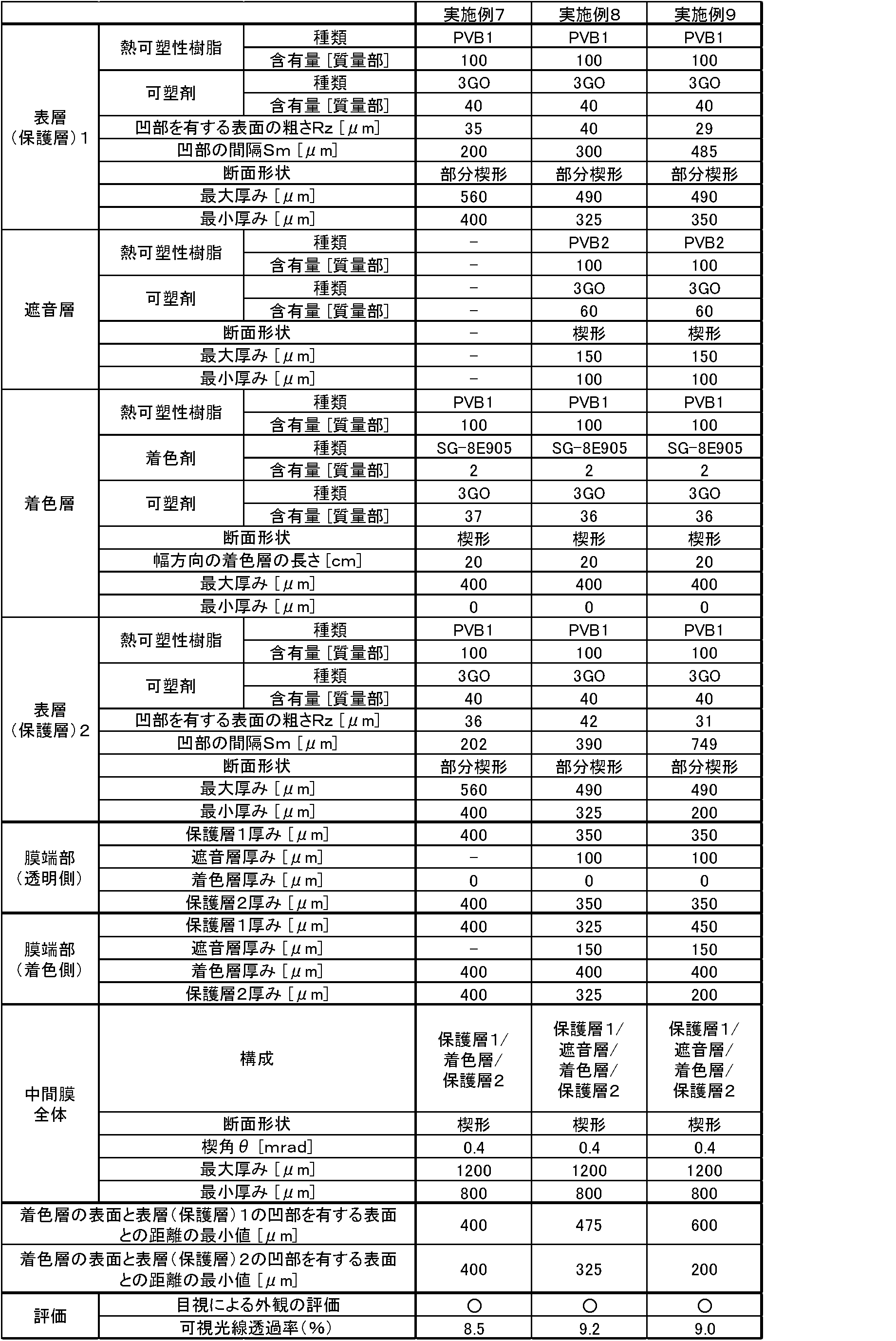

2 任意に選択した一の凹部に隣接する凹部
3 任意に選択した一の凹部に隣接する凹部
A 凹部1と凹部2との間隔
B 凹部1と凹部3との間隔
4 車両用合わせガラス
41 上辺部に沿って帯状になるように配置された着色層
51 合わせガラス用中間膜
511 断面が矩形の着色層
512 一方の表面に多数の凹部を有する表層
a 着色層の表層側の表面と表層の多数の凹部を有する表面との距離の最小値
52 合わせガラス用中間膜
521 断面が楔形の着色層
522 一方の表面に多数の凹部を有する表層
b 着色層の表層側の表面と表層の多数の凹部を有する表面との距離の最小値
6 合わせガラス用中間膜
61 一方の表面に多数の凹部を有する表層(第1の保護層)
62 遮音層
63 着色層
64 第2の保護層
Claims (6)
- 2層以上の積層構造を有する合わせガラス用中間膜であって、
少なくとも、合わせガラス用中間膜の最表面に配置される一方の表面に多数の凹部を有する表層と、着色剤を含有する着色層とを有し、
前記着色層の前記表層側の表面と、前記表層の多数の凹部を有する表面との距離の最小値が150μm以上である
ことを特徴とする合わせガラス用中間膜。 - JIS B 0601(1994)に準拠して測定した表層の多数の凹部を有する表面の十点平均粗さ(Rz)が15~60μmであることを特徴とする請求項1記載の合わせガラス用中間膜。
- 3層以上の積層構造を有することを特徴とする請求項1記載の合わせガラス用中間膜。
- 4層以上の積層構造を有することを特徴とする請求項2記載の合わせガラス用中間膜。
- 一方の表面に多数の凹部を有する表層(第1の保護層)、遮音層、着色層及び第2の保護層がこの順に積層された4層構造を有することを特徴とする請求項1記載の合わせガラス用中間膜。
- 請求項1、2、3、4又は5記載の合わせガラス用中間膜が、一対のガラス板の間に積層されていることを特徴とする合わせガラス。
Priority Applications (11)
| Application Number | Priority Date | Filing Date | Title |
|---|---|---|---|
| US15/562,033 US10414129B2 (en) | 2015-04-08 | 2016-04-07 | Interlayer for laminated glass and laminated glass |
| AU2016246965A AU2016246965A1 (en) | 2015-04-08 | 2016-04-07 | Interlayer for laminated glass and laminated glass |
| CN201680018693.4A CN107406313A (zh) | 2015-04-08 | 2016-04-07 | 夹层玻璃用中间膜和夹层玻璃 |
| EP16776652.6A EP3281924B1 (en) | 2015-04-08 | 2016-04-07 | Interlayer for laminated glass and laminated glass |
| RU2017134988A RU2017134988A (ru) | 2015-04-08 | 2016-04-07 | Промежуточный слой для многослойного стекла и многослойное стекло |
| MX2017012885A MX2017012885A (es) | 2015-04-08 | 2016-04-07 | Capa intermedia para vidrio laminado y vidrio laminado. |
| KR1020177026649A KR102601319B1 (ko) | 2015-04-08 | 2016-04-07 | 합판 유리용 중간막 및 합판 유리 |
| BR112017020937A BR112017020937B8 (pt) | 2015-04-08 | 2016-04-07 | Intercamada para vidro laminado e vidro laminado |
| CA2980712A CA2980712A1 (en) | 2015-04-08 | 2016-04-07 | Interlayer for laminated glass and laminated glass |
| JP2016531722A JP6791753B2 (ja) | 2015-04-08 | 2016-04-07 | 合わせガラス用中間膜及び合わせガラス |
| ZA2017/06880A ZA201706880B (en) | 2015-04-08 | 2017-10-11 | Interlayer for laminated glass and laminated glass |
Applications Claiming Priority (2)
| Application Number | Priority Date | Filing Date | Title |
|---|---|---|---|
| JP2015079355 | 2015-04-08 | ||
| JP2015-079355 | 2015-04-08 |
Publications (2)
| Publication Number | Publication Date |
|---|---|
| WO2016163486A1 true WO2016163486A1 (ja) | 2016-10-13 |
| WO2016163486A8 WO2016163486A8 (ja) | 2017-09-14 |
Family
ID=57072497
Family Applications (1)
| Application Number | Title | Priority Date | Filing Date |
|---|---|---|---|
| PCT/JP2016/061456 WO2016163486A1 (ja) | 2015-04-08 | 2016-04-07 | 合わせガラス用中間膜及び合わせガラス |
Country Status (13)
| Country | Link |
|---|---|
| US (1) | US10414129B2 (ja) |
| EP (1) | EP3281924B1 (ja) |
| JP (1) | JP6791753B2 (ja) |
| KR (1) | KR102601319B1 (ja) |
| CN (1) | CN107406313A (ja) |
| AU (1) | AU2016246965A1 (ja) |
| BR (1) | BR112017020937B8 (ja) |
| CA (1) | CA2980712A1 (ja) |
| MX (1) | MX2017012885A (ja) |
| RU (1) | RU2017134988A (ja) |
| TW (1) | TWI760300B (ja) |
| WO (1) | WO2016163486A1 (ja) |
| ZA (1) | ZA201706880B (ja) |
Cited By (6)
| Publication number | Priority date | Publication date | Assignee | Title |
|---|---|---|---|---|
| WO2018025937A1 (ja) * | 2016-08-03 | 2018-02-08 | 積水化学工業株式会社 | 着色合わせガラス用中間膜及び着色合わせガラス |
| CN110650930A (zh) * | 2017-06-07 | 2020-01-03 | 积水化学工业株式会社 | 夹层玻璃用中间膜和夹层玻璃 |
| WO2020040115A1 (ja) * | 2018-08-20 | 2020-02-27 | 積水化学工業株式会社 | 合わせガラスセット及び合わせガラス構造体 |
| WO2020040114A1 (ja) * | 2018-08-20 | 2020-02-27 | 積水化学工業株式会社 | 合わせガラス用中間膜、ロール体及び合わせガラスセットの製造方法 |
| EP3401092B1 (en) | 2017-05-10 | 2021-03-03 | Kuraray Europe GmbH | Interlayer film with shade band |
| EP3636613A4 (en) * | 2017-06-07 | 2021-03-24 | Sekisui Chemical Co., Ltd. | INTERMEDIATE LAYER FOR LAMINATED GLASS AND LAMINATED GLASS |
Families Citing this family (5)
| Publication number | Priority date | Publication date | Assignee | Title |
|---|---|---|---|---|
| JP6799136B2 (ja) * | 2016-07-18 | 2020-12-09 | サン−ゴバン グラス フランス | 乗り物複合ペインに取り付けられているセンサのための最適化された光線経路を有している乗り物複合ペイン |
| CN208906630U (zh) * | 2018-03-30 | 2019-05-28 | Skc株式会社 | 接合用层压膜及包含该接合用层压膜的透光层压体 |
| KR102050664B1 (ko) * | 2018-06-05 | 2019-11-29 | 에스케이씨 주식회사 | 유리접합용 필름, 이의 제조방법 및 이를 포함하는 이동수단 |
| KR102156988B1 (ko) | 2018-12-31 | 2020-09-16 | 에스케이씨 주식회사 | 유리접합용 필름, 이의 제조방법, 이를 포함하는 접합유리 및 이를 포함하는 이동수단 |
| EP4132782A1 (de) * | 2020-04-07 | 2023-02-15 | Saint-Gobain Glass France | Mehrlagige gefärbte zwischenschicht mit keilförmigem querschnitt |
Citations (5)
| Publication number | Priority date | Publication date | Assignee | Title |
|---|---|---|---|---|
| JPH0826789A (ja) * | 1994-07-22 | 1996-01-30 | Sekisui Chem Co Ltd | 合わせガラス用中間膜及びその製造装置並びにその製造方法 |
| JP2003221261A (ja) * | 2002-01-31 | 2003-08-05 | Yoshioka Tokujin Design Jimusho:Kk | 合わせガラス及びその製造方法 |
| JP2007055822A (ja) * | 2005-08-22 | 2007-03-08 | Sekisui Chem Co Ltd | 合わせガラス用中間膜および合わせガラス |
| JP2013006729A (ja) * | 2011-06-23 | 2013-01-10 | Sekisui Chem Co Ltd | 合わせガラス用中間膜及び合わせガラス |
| WO2015016366A1 (ja) * | 2013-08-01 | 2015-02-05 | 積水化学工業株式会社 | 合わせガラス用中間膜及び合わせガラス |
Family Cites Families (14)
| Publication number | Priority date | Publication date | Assignee | Title |
|---|---|---|---|---|
| JPS6161835A (ja) | 1984-08-31 | 1986-03-29 | Sekisui Chem Co Ltd | エンボス加工された熱可塑性樹脂シ−トの製造方法 |
| WO1992016369A1 (en) * | 1991-03-14 | 1992-10-01 | E.I. Du Pont De Nemours And Company | Process for preparation of colored thermoplastic composite sheeting for laminated structures |
| MXPA04008400A (es) * | 2002-02-28 | 2004-11-26 | Solutia Inc | Laminados reflejantes repujados. |
| MX2007009319A (es) * | 2005-02-03 | 2007-11-06 | Sekisui Chemical Co Ltd | Capa intermedia para vidrio laminado y vidrio laminado. |
| JP2007223883A (ja) * | 2005-12-26 | 2007-09-06 | Asahi Glass Co Ltd | 車両用合せガラス |
| GB0607745D0 (en) * | 2006-04-20 | 2006-05-31 | Pilkington Plc | Glazing |
| GB0607746D0 (en) * | 2006-04-20 | 2006-05-31 | Pilkington Plc | Glazing |
| JP4465333B2 (ja) | 2006-06-12 | 2010-05-19 | 積水化学工業株式会社 | 合わせガラス用中間膜及び合わせガラス |
| JP2008201667A (ja) * | 2007-01-24 | 2008-09-04 | Asahi Glass Co Ltd | 車両用合わせガラス |
| CN101687357B (zh) * | 2007-06-27 | 2014-01-15 | 积水化学工业株式会社 | 安全玻璃用多层中间膜的制造装置及制造方法 |
| EP2153989B1 (de) | 2008-08-01 | 2021-09-29 | Kuraray Europe GmbH | Mehrschichtfolien aus weichmacherhaltigem Polyvinylacetal mit schalldämpfenden Eigenschaften |
| US20120135191A1 (en) * | 2010-11-30 | 2012-05-31 | Lora Lee Spangler | Systems, Methods and Apparatuses for Direct Embossment of a Polymer Melt Sheet |
| US9574028B2 (en) * | 2013-04-09 | 2017-02-21 | Solutia Inc. | Embossed polymer sheet |
| MX2016001189A (es) | 2013-08-01 | 2016-06-02 | Sekisui Chemical Co Ltd | Pelicula de capa intermedia para vidrio laminado y vidrio laminado. |
-
2016
- 2016-04-07 US US15/562,033 patent/US10414129B2/en active Active
- 2016-04-07 CA CA2980712A patent/CA2980712A1/en not_active Abandoned
- 2016-04-07 KR KR1020177026649A patent/KR102601319B1/ko active IP Right Grant
- 2016-04-07 BR BR112017020937A patent/BR112017020937B8/pt active Search and Examination
- 2016-04-07 RU RU2017134988A patent/RU2017134988A/ru not_active Application Discontinuation
- 2016-04-07 WO PCT/JP2016/061456 patent/WO2016163486A1/ja active Application Filing
- 2016-04-07 AU AU2016246965A patent/AU2016246965A1/en not_active Abandoned
- 2016-04-07 MX MX2017012885A patent/MX2017012885A/es unknown
- 2016-04-07 EP EP16776652.6A patent/EP3281924B1/en active Active
- 2016-04-07 CN CN201680018693.4A patent/CN107406313A/zh active Pending
- 2016-04-07 JP JP2016531722A patent/JP6791753B2/ja active Active
- 2016-04-08 TW TW105111040A patent/TWI760300B/zh active
-
2017
- 2017-10-11 ZA ZA2017/06880A patent/ZA201706880B/en unknown
Patent Citations (5)
| Publication number | Priority date | Publication date | Assignee | Title |
|---|---|---|---|---|
| JPH0826789A (ja) * | 1994-07-22 | 1996-01-30 | Sekisui Chem Co Ltd | 合わせガラス用中間膜及びその製造装置並びにその製造方法 |
| JP2003221261A (ja) * | 2002-01-31 | 2003-08-05 | Yoshioka Tokujin Design Jimusho:Kk | 合わせガラス及びその製造方法 |
| JP2007055822A (ja) * | 2005-08-22 | 2007-03-08 | Sekisui Chem Co Ltd | 合わせガラス用中間膜および合わせガラス |
| JP2013006729A (ja) * | 2011-06-23 | 2013-01-10 | Sekisui Chem Co Ltd | 合わせガラス用中間膜及び合わせガラス |
| WO2015016366A1 (ja) * | 2013-08-01 | 2015-02-05 | 積水化学工業株式会社 | 合わせガラス用中間膜及び合わせガラス |
Cited By (19)
| Publication number | Priority date | Publication date | Assignee | Title |
|---|---|---|---|---|
| US10926515B2 (en) | 2016-08-03 | 2021-02-23 | Sekisui Chemical Co., Ltd. | Interlayer film for colored laminated glass, and colored laminated glass |
| WO2018025932A1 (ja) * | 2016-08-03 | 2018-02-08 | 積水化学工業株式会社 | 着色合わせガラス用中間膜及び着色合わせガラス |
| US11724480B2 (en) | 2016-08-03 | 2023-08-15 | Sekisui Chemical Co., Ltd. | Interlayer film for colored laminated glass, and colored laminated glass |
| WO2018025937A1 (ja) * | 2016-08-03 | 2018-02-08 | 積水化学工業株式会社 | 着色合わせガラス用中間膜及び着色合わせガラス |
| US11117351B2 (en) | 2016-08-03 | 2021-09-14 | Sekisui Chemical Co., Ltd. | Interlayer film for colored laminated glass, and colored laminated glass |
| EP3401092B1 (en) | 2017-05-10 | 2021-03-03 | Kuraray Europe GmbH | Interlayer film with shade band |
| CN110650930B (zh) * | 2017-06-07 | 2022-04-19 | 积水化学工业株式会社 | 夹层玻璃用中间膜和夹层玻璃 |
| EP3636613A4 (en) * | 2017-06-07 | 2021-03-24 | Sekisui Chemical Co., Ltd. | INTERMEDIATE LAYER FOR LAMINATED GLASS AND LAMINATED GLASS |
| EP3636614A4 (en) * | 2017-06-07 | 2021-03-24 | Sekisui Chemical Co., Ltd. | INTERMEDIATE LAYER FOR LAMINATED GLASS AND LAMINATED GLASS |
| US11084254B2 (en) | 2017-06-07 | 2021-08-10 | Sekisui Chemical Co., Ltd. | Interlayer for laminated glass, and laminated glass |
| KR20200016823A (ko) * | 2017-06-07 | 2020-02-17 | 세키스이가가쿠 고교가부시키가이샤 | 접합 유리용 중간막 및 접합 유리 |
| US11376819B2 (en) | 2017-06-07 | 2022-07-05 | Sekisui Chemical Co., Ltd. | Interlayer for laminated glass, and laminated glass |
| US11590736B2 (en) | 2017-06-07 | 2023-02-28 | Sekisui Chemical Co., Ltd. | Interlayer for laminated glass, and laminated glass |
| US11590735B2 (en) | 2017-06-07 | 2023-02-28 | Sekisui Chemical Co., Ltd. | Interlayer for laminated glass, and laminated glass |
| KR102524218B1 (ko) * | 2017-06-07 | 2023-04-21 | 세키스이가가쿠 고교가부시키가이샤 | 접합 유리용 중간막 및 접합 유리 |
| CN110650930A (zh) * | 2017-06-07 | 2020-01-03 | 积水化学工业株式会社 | 夹层玻璃用中间膜和夹层玻璃 |
| WO2020040114A1 (ja) * | 2018-08-20 | 2020-02-27 | 積水化学工業株式会社 | 合わせガラス用中間膜、ロール体及び合わせガラスセットの製造方法 |
| WO2020040115A1 (ja) * | 2018-08-20 | 2020-02-27 | 積水化学工業株式会社 | 合わせガラスセット及び合わせガラス構造体 |
| US11945191B2 (en) | 2018-08-20 | 2024-04-02 | Sekisui Chemical Co., Ltd. | Laminated glass set and laminated glass structure |
Also Published As
| Publication number | Publication date |
|---|---|
| CN107406313A (zh) | 2017-11-28 |
| KR20170134388A (ko) | 2017-12-06 |
| EP3281924A1 (en) | 2018-02-14 |
| BR112017020937B1 (pt) | 2022-03-22 |
| JP6791753B2 (ja) | 2020-11-25 |
| RU2017134988A (ru) | 2019-04-05 |
| JPWO2016163486A1 (ja) | 2018-02-01 |
| KR102601319B1 (ko) | 2023-11-10 |
| BR112017020937B8 (pt) | 2023-10-10 |
| EP3281924A4 (en) | 2018-12-26 |
| US20180104934A1 (en) | 2018-04-19 |
| MX2017012885A (es) | 2018-01-15 |
| AU2016246965A1 (en) | 2017-10-12 |
| RU2017134988A3 (ja) | 2019-09-26 |
| CA2980712A1 (en) | 2016-10-13 |
| EP3281924B1 (en) | 2022-08-24 |
| ZA201706880B (en) | 2019-01-30 |
| US10414129B2 (en) | 2019-09-17 |
| TW201702070A (zh) | 2017-01-16 |
| TWI760300B (zh) | 2022-04-11 |
| WO2016163486A8 (ja) | 2017-09-14 |
| BR112017020937A2 (pt) | 2018-07-10 |
Similar Documents
| Publication | Publication Date | Title |
|---|---|---|
| WO2016163486A1 (ja) | 合わせガラス用中間膜及び合わせガラス | |
| JP6568356B2 (ja) | 車両用フロントガラスの製造方法 | |
| JP6564570B2 (ja) | 合わせガラス用中間膜及び合わせガラス | |
| JP5676773B2 (ja) | 合わせガラス用中間膜及び合わせガラス | |
| JP6170638B1 (ja) | 合わせガラス用中間膜及び合わせガラス | |
| TWI749041B (zh) | 著色之層合玻璃用中間膜及著色之層合玻璃 | |
| US11648754B2 (en) | Interlayer for laminated glass, and laminated glass | |
| WO2015016366A1 (ja) | 合わせガラス用中間膜及び合わせガラス | |
| WO2015016358A1 (ja) | 合わせガラス用中間膜及び合わせガラス | |
| WO2016052603A1 (ja) | 合わせガラス用中間膜、合わせガラス及び合わせガラス用中間膜の製造方法 | |
| KR102341992B1 (ko) | 접합 유리용 중간막 및 접합 유리 | |
| TWI755512B (zh) | 層合玻璃用中間膜及層合玻璃 | |
| TWI714752B (zh) | 層合玻璃用中間膜及層合玻璃 | |
| KR102302429B1 (ko) | 접합 유리용 중간막, 롤체 및 접합 유리 | |
| WO2017171018A1 (ja) | 合わせガラス用中間膜及び合わせガラス | |
| KR20220057668A (ko) | 접합 유리용 중간막 및 접합 유리 | |
| JP2017178676A (ja) | 合わせガラス用中間膜、合わせガラス及び合わせガラス用中間膜の製造方法 | |
| TW202108376A (zh) | 層合玻璃用中間膜、輥體及層合玻璃 | |
| WO2023200014A1 (ja) | 合わせガラス用中間膜及びその製造方法、並びに、合わせガラス及びその製造方法 | |
| WO2023200013A1 (ja) | 合わせガラス用中間膜及びその製造方法、並びに、合わせガラス及びその製造方法 |
Legal Events
| Date | Code | Title | Description |
|---|---|---|---|
| ENP | Entry into the national phase |
Ref document number: 2016531722 Country of ref document: JP Kind code of ref document: A |
|
| 121 | Ep: the epo has been informed by wipo that ep was designated in this application |
Ref document number: 16776652 Country of ref document: EP Kind code of ref document: A1 |
|
| ENP | Entry into the national phase |
Ref document number: 20177026649 Country of ref document: KR Kind code of ref document: A |
|
| ENP | Entry into the national phase |
Ref document number: 2980712 Country of ref document: CA |
|
| WWE | Wipo information: entry into national phase |
Ref document number: 15562033 Country of ref document: US |
|
| WWE | Wipo information: entry into national phase |
Ref document number: 2017134988 Country of ref document: RU |
|
| WWE | Wipo information: entry into national phase |
Ref document number: MX/A/2017/012885 Country of ref document: MX |
|
| NENP | Non-entry into the national phase |
Ref country code: DE |
|
| REG | Reference to national code |
Ref country code: BR Ref legal event code: B01A Ref document number: 112017020937 Country of ref document: BR |
|
| ENP | Entry into the national phase |
Ref document number: 2016246965 Country of ref document: AU Date of ref document: 20160407 Kind code of ref document: A |
|
| ENP | Entry into the national phase |
Ref document number: 112017020937 Country of ref document: BR Kind code of ref document: A2 Effective date: 20170929 |