WO2016163316A1 - 車両用表示装置 - Google Patents
車両用表示装置 Download PDFInfo
- Publication number
- WO2016163316A1 WO2016163316A1 PCT/JP2016/060910 JP2016060910W WO2016163316A1 WO 2016163316 A1 WO2016163316 A1 WO 2016163316A1 JP 2016060910 W JP2016060910 W JP 2016060910W WO 2016163316 A1 WO2016163316 A1 WO 2016163316A1
- Authority
- WO
- WIPO (PCT)
- Prior art keywords
- display device
- vehicle
- dimensional object
- display panel
- cylindrical body
- Prior art date
- Legal status (The legal status is an assumption and is not a legal conclusion. Google has not performed a legal analysis and makes no representation as to the accuracy of the status listed.)
- Ceased
Links
Images




Classifications
-
- B—PERFORMING OPERATIONS; TRANSPORTING
- B60—VEHICLES IN GENERAL
- B60K—ARRANGEMENT OR MOUNTING OF PROPULSION UNITS OR OF TRANSMISSIONS IN VEHICLES; ARRANGEMENT OR MOUNTING OF PLURAL DIVERSE PRIME-MOVERS IN VEHICLES; AUXILIARY DRIVES FOR VEHICLES; INSTRUMENTATION OR DASHBOARDS FOR VEHICLES; ARRANGEMENTS IN CONNECTION WITH COOLING, AIR INTAKE, GAS EXHAUST OR FUEL SUPPLY OF PROPULSION UNITS IN VEHICLES
- B60K35/00—Instruments specially adapted for vehicles; Arrangement of instruments in or on vehicles
- B60K35/20—Output arrangements, i.e. from vehicle to user, associated with vehicle functions or specially adapted therefor
- B60K35/21—Output arrangements, i.e. from vehicle to user, associated with vehicle functions or specially adapted therefor using visual output, e.g. blinking lights or matrix displays
- B60K35/22—Display screens
-
- G—PHYSICS
- G01—MEASURING; TESTING
- G01D—MEASURING NOT SPECIALLY ADAPTED FOR A SPECIFIC VARIABLE; ARRANGEMENTS FOR MEASURING TWO OR MORE VARIABLES NOT COVERED IN A SINGLE OTHER SUBCLASS; TARIFF METERING APPARATUS; MEASURING OR TESTING NOT OTHERWISE PROVIDED FOR
- G01D13/00—Component parts of indicators for measuring arrangements not specially adapted for a specific variable
- G01D13/02—Scales; Dials
-
- G—PHYSICS
- G01—MEASURING; TESTING
- G01D—MEASURING NOT SPECIALLY ADAPTED FOR A SPECIFIC VARIABLE; ARRANGEMENTS FOR MEASURING TWO OR MORE VARIABLES NOT COVERED IN A SINGLE OTHER SUBCLASS; TARIFF METERING APPARATUS; MEASURING OR TESTING NOT OTHERWISE PROVIDED FOR
- G01D13/00—Component parts of indicators for measuring arrangements not specially adapted for a specific variable
- G01D13/02—Scales; Dials
- G01D13/04—Construction
-
- G—PHYSICS
- G01—MEASURING; TESTING
- G01D—MEASURING NOT SPECIALLY ADAPTED FOR A SPECIFIC VARIABLE; ARRANGEMENTS FOR MEASURING TWO OR MORE VARIABLES NOT COVERED IN A SINGLE OTHER SUBCLASS; TARIFF METERING APPARATUS; MEASURING OR TESTING NOT OTHERWISE PROVIDED FOR
- G01D13/00—Component parts of indicators for measuring arrangements not specially adapted for a specific variable
- G01D13/02—Scales; Dials
- G01D13/12—Graduation
- G01D13/20—Graduation with luminescent markings
-
- G—PHYSICS
- G01—MEASURING; TESTING
- G01D—MEASURING NOT SPECIALLY ADAPTED FOR A SPECIFIC VARIABLE; ARRANGEMENTS FOR MEASURING TWO OR MORE VARIABLES NOT COVERED IN A SINGLE OTHER SUBCLASS; TARIFF METERING APPARATUS; MEASURING OR TESTING NOT OTHERWISE PROVIDED FOR
- G01D7/00—Indicating measured values
Definitions
- This case relates to a vehicle display device.
- Vehicles such as automobiles have an instrument panel at the front of the passenger compartment.
- the instrument panel is provided with an instrument device for displaying information necessary for operation.
- an instrument device for displaying information necessary for operation.
- a mechanical analog meter or the like is usually used for such an instrument device.
- This mechanical instrument device (analog meter) is expensive because it includes various configurations such as a pointer driving device such as a stepping motor and a pointer control circuit.
- a display panel such as a liquid crystal panel is also installed inside or outside the instrument device.
- the mechanical instrument device described above is installed in front of the driver's seat, and a transmission / reflection member such as a half mirror is disposed on the front side of the instrument device, and an image is projected onto the transmission / reflection member.
- a display panel that displays a virtual image of an image projected on a transmission / reflection member in an overlapping manner on an instrument device has been developed (see, for example, Patent Document 1 and Patent Document 2).
- Patent Literature 1 and Patent Literature 2 described above use both an existing mechanical instrument device and a display panel, and thus cost is high. Moreover, since the image of the display panel is superimposed on the instrument device having a flat dial, it is difficult to obtain a sufficient stereoscopic effect and the stereoscopic display effect is low. It was. Moreover, since the thing of the patent document 2 has made it superimpose the image of a display panel on the instrument apparatus which has a three-dimensional dial plate, although it can obtain a three-dimensional effect, Since a small image by a display panel is superimposed on a narrow range, the image display effect is monotonous and simple.
- Patent Document 3 not a mechanical instrument device but a three-dimensional object (modeled object) having a tapered inclined surface imitating a road has been proposed. Since the three-dimensional object having the inclined surface is too specialized in shape, it can only be used for a single application such as route guidance.
- the main purpose of this case is to solve the above-mentioned problems.
- a three-dimensional object is installed in front of the driver's seat, A transmission / reflection member is disposed on the front side of the three-dimensional object, A display panel capable of projecting an image on the transmissive reflecting member and displaying a virtual image of the image projected on the transmissive reflecting member on the three-dimensional object;
- the three-dimensional object extends from the front side to the back side, and at least part of the three-dimensional object is a cylindrical body having a reduced diameter portion that reduces the diameter from the front side to the back side,
- the cylindrical body is an instrument constituent member that forms a pointer turning region inside, and
- the display panel is capable of displaying a virtual image of a pointer inside the instrument constituent member.
- the above configuration eliminates the need for an expensive mechanical instrument device (analog meter) or the like by the configuration having the three-dimensional object having a cylindrical body, the transmission / reflection member, and the display panel. It is possible to display various and versatile displays that are excellent.
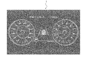
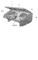
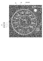
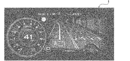
- FIG. 2 is a front view of FIG. 1 showing a first display example. It is a perspective view of the non-display state of FIG.
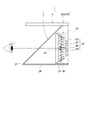
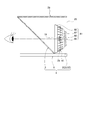
- FIG. 4 is a side view of FIG. 3.
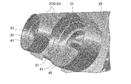
- FIG. 4 is a perspective view of the three-dimensional object in FIG. 3. It is the perspective view (single-item figure) which looked at the solid object of FIG. 5 from another direction. It is the figure which expanded the display of the left side part of FIG. It is a modification of FIG.
- It is a front view which shows the 2nd example of a display. It is a front view which shows the 3rd example of a display. It is a front view which shows the 4th example of a display.
- the back side and the near side are based on a person viewing the vehicle display device. Therefore, the back side is the vehicle front side, and the front side is the vehicle rear side.
- Vehicles such as automobiles have an instrument panel at the front of the passenger compartment. As shown in FIGS. 1 and 2, a vehicle display device 1 that displays information is provided in front of the driver's seat of the instrument panel.
- the front side of the driver's seat is a portion of the instrument panel on the driver's seat side, a center portion in the width direction, or the like.
- the vehicle display device 1 is as follows.
- the three-dimensional object 2 is installed in front of the driver's seat.
- a transmission / reflection member 3 is disposed on the front side of the three-dimensional object 2.
- a display panel 5 is provided that can project an image on the transmission / reflection member 3 and display a virtual image of the image projected on the transmission / reflection member 3 on the three-dimensional object 2.
- the above-described three-dimensional object 2 is an object (modeled object) made of metal or resin that does not have at least mechanical parts such as a pointer driving device (for example, a stepping motor). Details of the three-dimensional object 2 will be described later.
- the transmission / reflection member 3 is, for example, a half mirror.
- the display panel 5 is, for example, a liquid crystal panel, an organic EL panel, or the like.
- the transmission / reflection member 3 is inclined and arranged at an angle to reflect the display on the display panel 5 so as to overlap the three-dimensional object 2 when viewed from the front side.
- the three-dimensional object 2 includes a cylindrical body 22 that extends from the near side toward the far side.
- the cylindrical body 22 has a reduced diameter portion 21 that is reduced in diameter from the near side to the far side at least partially.
- the cylindrical body 22 is, for example, cylindrical or rectangular.
- the cylindrical body 22 has a cylindrical shape as a basic shape.
- the reduced diameter portion 21 is, for example, a substantially conical (or pyramidal) or a partial conical (or partial pyramidal) portion.
- the cylindrical body 22 has an inner / outer double cylinder structure having a cylindrical outer cylinder portion and an inner cylinder portion inside thereof.
- the outer cylinder part and the inner cylinder part are connected on the front side.
- the inner cylinder part is mainly used for display.
- the cylindrical body 22 (the inner cylinder portion thereof) is almost entirely the reduced diameter portion 21.
- One or a plurality of such cylindrical bodies 22 can be provided.
- two cylindrical bodies 22 are arranged side by side.
- the two cylindrical bodies 22 are integrated with the back side attached to the mounting plate 25.
- the two cylindrical bodies 22 are accommodated inside the frame-shaped housing 26 (see FIGS. 3 and 4) together with the mounting plate 25.
- the above-described transmission / reflection member 3 is attached so as to cover the opening 27 of the housing 26.
- the display panel 5 described above is installed so as to protrude from the edge of the opening 27 toward the front side of the housing 26 (or go out of the housing 26).
- the display panel 5 has a size that covers the entire area of the opening 27 or the mounting plate 25.
- the cylindrical body 22 has a protruding portion 31 extending from the back side toward the near side at the axial center position.
- the protrusion 31 can be formed into a thin cylindrical shape, a prismatic shape, or other shapes.
- the flat surface can be used for a display area or the like.
- the cylindrical body 22 has a step portion 41 at or around the position where the image of the display panel 5 is displayed in the intermediate portion in the axial direction.
- the position where the image of the display panel 5 is displayed is the position where the image (virtual image) of the display panel 5 projected on the transmission / reflection member 3 is formed.
- the step portion 41 is provided at a position in the middle of the reduced diameter portion 21.
- the reduced diameter portion 21 may have the same inclination angle on the near side and the far side of the stepped portion 41. Alternatively, the inclination angle may be varied.
- the cylindrical body 22 serves as an instrument constituent member 52 that forms a pointer turning region therein.
- the said display panel 5 shall display the virtual image of the pointer 53 inside the instrument structural member 52, as shown in FIG.
- the pointer turning region is literally a substantially circular region in which the needle 53 is turned in a mechanical instrument device (analog meter).
- a mechanical instrument device analog meter
- the instrument constituting member 52 is a partition member for setting the inside to be a pointer turning area and the outside to be another display area. Therefore, it is preferable that the meter component 52 has a circular cross section.
- the pointer 53 or light of a color different from the illumination color of the cylindrical body 22 (partial light emitting portion 55) described later may be displayed on the tip of the pointer 53 by display.
- Such a partial light emitting unit 55 can be created by the indication pointer 53 by display.
- the display panel 5 may display a scale part (for a speedometer, a tachometer, etc.) or a numerical value display part inside the pointer rotation area.
- a scale part for a speedometer, a tachometer, etc.
- a numerical value display part inside the pointer rotation area.
- the virtual image of the pointer 53 can be displayed on the back side of the tip of the protrusion 31.
- the three-dimensional object 2 includes the illumination unit 61.
- the said transmission / reflection member 3 shall have the transmittance
- the illumination unit 61 includes a light source such as an LED provided inside or on the back side of the three-dimensional object 2 and a window for transmitting light from the light source to the front surface side of the three-dimensional object 2. It is said.
- the window can be provided with a light transmissive member made of a transparent or translucent (colored or colorless) resin.
- the light source and the light transmitting member can be colored in an arbitrary color, and the light source can be changed in color.
- the illumination part 61 can also be comprised by the display of the display panel 5.
- the three-dimensional object 2 includes at least a front side illumination unit 65 and a back side illumination unit 66 as the illumination unit 61.
- the three-dimensional object 2 may include an intermediate illumination unit 67 and a protrusion tip illumination unit 68 as the illumination unit 61.
- the near side illumination part 65 is made into the circle
- the back side illumination part 66 is a circle indicating the inner boundary of the scale part (small scale) and the numerical value display part.
- the intermediate illumination part 67 is located between the front side illumination part 65 and the back side illumination part 66, and is a plurality of radial lines indicating a scale (for example, a large scale).
- the intermediate illumination part 67 is formed so as to pass through the position of the step part 41 described above.
- the protrusion tip illumination unit 68 is circular.
- the transmission / reflection member 3 is made of a dark color or smoked.
- a plurality of the illumination units 61 are provided at different positions in the vehicle front-rear direction with respect to the three-dimensional object 2. And the illumination part 61 from which a position differs in the vehicle front-back direction can be illuminated so that the near side may become bright and the back side may become dark.
- the front side illumination unit 65 is illuminated brightly, and the back side illumination unit 66 is illuminated more darkly than the front side illumination unit 65. Further, the projection tip illumination unit 68 is the brightest highlight illumination.
- the difference in brightness can be implemented by a difference in light source or a difference in current applied to the light source.
- the display panel 5 is arranged to face downward on the upper side.
- the transmission / reflection member 3 is arranged in a forward tilted state.
- the display panel 5 is attached to the position of the upper edge of the opening 27 of the housing 26 in a substantially horizontal state.
- the display panel 5 is positioned on the upper side of the transmission / reflection member 3.
- the display panel 5 is arranged on the lower side facing upward. And the said transmission / reflection member 3 is arrange
- the display panel 5 is attached to the position of the lower edge of the opening 27 of the housing 26 in a substantially horizontal state.
- the display panel 5 is located below the transmissive reflecting member 3.
- the three-dimensional object 2, the transmission / reflection member 3, and the display panel 5 constitute the vehicle display device 1. Then, by projecting the image of the display panel 5 onto the transmission / reflection member 3, as shown in FIG. 2 and the like (see also other display examples of FIGS. 9 to 11), the image is projected onto the transmission / reflection member 3.
- the virtual image of the image can be superimposed on the three-dimensional object 2 installed in front of the driver's seat and displayed like project mapping. Thereby, the image of the display panel 5 can be shown as a three-dimensional display, and the vehicle display device 1 having a new display effect can be obtained.
- the three-dimensional object 2 has a cylindrical body 22. Thereby, various images can be displayed by using the inner area and the outer area partitioned by the cylindrical body 22, respectively. Since the cylindrical body 22 is not unique in shape, it can be used for various purposes. In addition, by providing a plurality of cylindrical bodies 22, it is possible to divide the display area of the display panel 5 into a plurality of parts and perform various and multipurpose displays.
- the cylindrical body 22 has the reduced diameter part 21 at least in part, thereby giving a stereoscopic display effect with a sense of perspective to the image displayed inside the cylindrical body 22. be able to.
- a protrusion 31 is provided at the axial center of the cylindrical body 22. Due to the presence of the protrusions 31, it is possible to give a stereoscopic display effect with a sense of perspective to the image displayed on the inner side of the cylindrical body 22 by a contrast effect. In addition, the three-dimensional display effect of the protrusion 31 can be further enhanced by the cooperative action with the reduced diameter portion 21. For example, when the tip portion of the protrusion 31 is regarded as a pointer cap, as will be described later, when the pointer 53 is displayed as an image inside the cylindrical body 22, the pointer 53 can be seen as a real one. In addition, for example, the flat surface at the tip of the protrusion 31 can be used as an independent display area.
- a step 41 is provided at or around the position where the image of the cylindrical body 22 is displayed. This makes it possible to adjust the position at which the image of the display panel 5 is displayed in accordance with the stepped portion 41 when the vehicle display device 1 is manufactured, and to provide a highly accurate vehicle display device with no variation in the display position. 1 can be manufactured. Moreover, the three-dimensional display effect can be enhanced by associating the stepped portion 41 with the display on the display panel 5. For example, as will be described later, when the pointer 53 is displayed by an image at the position of the step portion 41 of the cylindrical body 22, the parallax between the scale formed by the illumination of the illumination unit 61 on the cylindrical body 22 and the pointer 53 by the display Can be eliminated.
- the protrusion 31 can be seen as a pointer cap. Further, by providing the stepped portion 41 on the cylindrical body 22, the stepped portion 41 can be set to the current position of the pointer 53 so that the position indicated by the displayed pointer 53 can be clearly recognized. On the contrary, as shown on the right side of FIG. 9, by not displaying the pointer 53 inside the instrument component 52, it is possible to make the inside of the cylindrical body 22 an area for displaying other than the instrument part. Become.
- the virtual image of the pointer 53 is displayed on the back side of the tip of the protrusion 31.
- the pointer 53 can be seen to extend sideways from the back side of the pointer cap at the tip of the protrusion 31, and the three-dimensional effect around the pointer 53 is improved, making the pointer 53 more authentic. Can show.
- it is effective to display the pointer 53 at the position of the step portion 41 as described above.
- the three-dimensional object 2 has the illumination unit 61, and the transmission / reflection member 3 has a transmittance that makes the three-dimensional object 2 invisible.
- the illumination unit 61 when the illumination unit 61 is not illuminated, the three-dimensional object 2 becomes invisible, so that in FIG. 10 (when only the three-dimensional object 2 on the right side in the drawing is turned off) and FIG. 11 (when both three-dimensional objects 2 are turned off).
- the image on the display panel 5 is projected as it is onto the transmission / reflection member 3.
- the image of the display panel 5 can be expanded and displayed without being obstructed by the three-dimensional object 2. Note that specific transmittance can be set and adjusted by trial and error.
- FIG. 2 when an imaginary instrument part is created, as shown in FIG. 2, two or more instrument parts exist, and a flat image of the display panel 5 (for example, between them) (for example, , A route display screen, etc.). Further, as shown in FIG. 9, there is one instrument section, another circular display area, and a flat image (for example, a route display screen) of the display panel 5 between them. Can be displayed. Furthermore, as shown in FIG. 10, there can be a display in which one instrument unit is present and the entire outside thereof becomes a planar image (for example, a car navigation screen) of the display panel 5. Further, when the instrument unit is eliminated, as shown in FIG. 11, it is possible to perform display in which the instrument unit is not present and the entire surface is a planar full image (for example, a car navigation screen) of the display panel 5.
- FIG. 10 when the instrument unit is eliminated, as shown in FIG. 11, it is possible to perform display in which the instrument unit is not present and the entire surface is a planar full image (for example, a car navigation
- the illumination unit 61 having a different position in the vehicle front-rear direction can be illuminated so that the front side is bright and the back side is dark.
- the stereoscopic effect of the display can be further emphasized by making it feel that the near side is closer and the far side is further away due to the difference in brightness of the illumination.
- by illuminating the back side to be dark it is possible to generate a stereoscopic effect while maintaining contrast with the image display.
- the brightest highlight illumination is performed on the projection tip illumination unit 68 and is combined with the pointer 53 by the image, so that the pointer 53 by the image has an actual pointer cap. It is possible to make it appear as if it is the pointer 53, and the texture can be improved.
- a marker is displayed on the display panel 5 on the inner part of the three-dimensional object 2 that is illuminated, and the brightness of the marker is detected by a sensor installed on the surface of the display panel 5. It is also possible to control the brightness of the illumination of the three-dimensional object 2 so as to have a sense of unity with the display on the display panel 5.
Landscapes
- Engineering & Computer Science (AREA)
- Physics & Mathematics (AREA)
- General Physics & Mathematics (AREA)
- Chemical & Material Sciences (AREA)
- Combustion & Propulsion (AREA)
- Transportation (AREA)
- Mechanical Engineering (AREA)
- Instrument Panels (AREA)
- Details Of Measuring Devices (AREA)
- Indicating Measured Values (AREA)
Abstract
高価な機械式の計器装置(アナログメータ)などを不要化すると共に、立体感に優れた多様で多目的な表示を行うことができるようにする。 運転席の前方に情報を表示可能な車両用表示装置(1)に関する。 運転席の前方に立体物(2)が設置されている。 この立体物(2)の手前側に透過反射部材(3)が配設されている。 この透過反射部材(3)に画像を投影して、透過反射部材(3)に投影された画像の虚像を上記立体物(2)に重ねて表示可能な表示パネル(5)が設けられている。 上記立体物が、手前側から奥側へ向かって延びると共に、少なくとも一部に手前側から奥側へ向けて縮径する縮径部(21)を有する筒状体(22)とされている。 上筒状体(22)が、内部に指針回動領域を形成する計器構成部材(52)とされている。 上記表示パネル(5)が、計器構成部材(52)の内側に指針(53)の虚像を表示可能とされている。
Description
本件は、車両用表示装置に関するものである。
自動車などの車両には、車室内の前部にインストルメントパネルが設けられている。このインストルメントパネルには、運転に必要な情報を表示するための計器装置が設けられている。このような計器装置には、通常、機械式のアナログメータなどが用いられている。この機械式の計器装置(アナログメータ)は、ステッピングモータなどの指針駆動装置や、指針制御回路などの各種の構成を備えているため、高価なものとなっている。
そして、この計器装置の内部や外部などに対して液晶パネルなどの表示パネルを設置することも行われている。
これに対し、運転席の前方に上記した機械式の計器装置を設置し、この計器装置の手前側にハーフミラーなどの透過反射部材を配設すると共に、この透過反射部材に画像を投影して、透過反射部材に投影された画像の虚像を計器装置に重ねて表示させる表示パネルを設けるようにしたものも開発されている(例えば、特許文献1、特許文献2参照)。
しかしながら、上記特許文献1および特許文献2に記載された車両用表示装置は、既存の機械式の計器装置と、表示パネルとの両方を用いていたため、コストが高くなっていた。
しかも、特許文献1のものは、平面的な文字板を有する計器装置に対して表示パネルの画像を重ねるようにしているので、十分な立体感を得ることが難しく、立体的な表示効果が低かった。
また、特許文献2のものは、立体的な文字板を有する計器装置に対して表示パネルの画像を単純に重ねるようにしているので、立体感を得ることはできるものの、立体的な文字板の狭い範囲に対して表示パネルによる小さな画像を重ねるようにしているため、画像の表示効果が単調で単純なものとなっていた。
なお、特許文献3のように、機械式の計器装置ではなく、道路を模した先細りの傾斜面を有する立体的なオブジェ(造形物)を配置するようにしたものも提案されているが、先細りの傾斜面を有する立体的なオブジェは、形状があまりにも特化され過ぎているため、経路案内などの単一の用途にしか使用することができなかった。
しかも、特許文献1のものは、平面的な文字板を有する計器装置に対して表示パネルの画像を重ねるようにしているので、十分な立体感を得ることが難しく、立体的な表示効果が低かった。
また、特許文献2のものは、立体的な文字板を有する計器装置に対して表示パネルの画像を単純に重ねるようにしているので、立体感を得ることはできるものの、立体的な文字板の狭い範囲に対して表示パネルによる小さな画像を重ねるようにしているため、画像の表示効果が単調で単純なものとなっていた。
なお、特許文献3のように、機械式の計器装置ではなく、道路を模した先細りの傾斜面を有する立体的なオブジェ(造形物)を配置するようにしたものも提案されているが、先細りの傾斜面を有する立体的なオブジェは、形状があまりにも特化され過ぎているため、経路案内などの単一の用途にしか使用することができなかった。
そこで、本件は、上記した問題点を解決することを、主な目的としている。
上記課題を解決するために、本件は、
運転席の前方に情報を表示可能な車両用表示装置において、
運転席の前方に立体物が設置されており、
該立体物の手前側に透過反射部材が配設されており、
該透過反射部材に画像を投影して、透過反射部材に投影された画像の虚像を前記立体物に重ねて表示可能な表示パネルが設けられていると共に、
前記立体物が、手前側から奥側へ向かって延びると共に、少なくとも一部に手前側から奥側へ向けて縮径する縮径部を有する筒状体とされており、
該筒状体が、内部に指針回動領域を形成する計器構成部材とされていると共に、
前記表示パネルが、計器構成部材の内側に指針の虚像を表示可能とされていることを特徴とする。
運転席の前方に情報を表示可能な車両用表示装置において、
運転席の前方に立体物が設置されており、
該立体物の手前側に透過反射部材が配設されており、
該透過反射部材に画像を投影して、透過反射部材に投影された画像の虚像を前記立体物に重ねて表示可能な表示パネルが設けられていると共に、
前記立体物が、手前側から奥側へ向かって延びると共に、少なくとも一部に手前側から奥側へ向けて縮径する縮径部を有する筒状体とされており、
該筒状体が、内部に指針回動領域を形成する計器構成部材とされていると共に、
前記表示パネルが、計器構成部材の内側に指針の虚像を表示可能とされていることを特徴とする。
本件によれば、上記構成によって、筒状体を有する上記立体物と透過反射部材と表示パネルとを有する構成によって、高価な機械式の計器装置(アナログメータ)などを不要化すると共に、立体感に優れた多様で多目的な表示を行うことができる。
以下、本実施の形態を、図面を用いて詳細に説明する。
図1~図11は、この実施の形態を説明するためのものである。なお、奥側および手前側は、車両用表示装置を見る者を基準としている。よって、奥側は車両前方側となり、手前側は車両後方側となる。
図1~図11は、この実施の形態を説明するためのものである。なお、奥側および手前側は、車両用表示装置を見る者を基準としている。よって、奥側は車両前方側となり、手前側は車両後方側となる。
<構成>以下、この実施例の構成について説明する。
自動車などの車両には、車室内の前部にインストルメントパネルが設けられている。このインストルメントパネルの運転席の前方に対し、図1、図2に示すように、情報を表示させるようにした車両用表示装置1を設ける。ここで、運転席の前方は、インストルメントパネルの、運転席側の部分や幅方向の中央部などのことである。
この実施例では、車両用表示装置1を以下のようなものとする。
(1)図3、図4に示すように、運転席の前方に立体物2が設置される。
この立体物2の手前側に透過反射部材3が配設される。
この透過反射部材3に画像を投影して、透過反射部材3に投影された画像の虚像を上記立体物2に重ねて表示可能な表示パネル5が設けられる。
この立体物2の手前側に透過反射部材3が配設される。
この透過反射部材3に画像を投影して、透過反射部材3に投影された画像の虚像を上記立体物2に重ねて表示可能な表示パネル5が設けられる。
ここで、上記した立体物2は、少なくとも指針駆動装置(例えば、ステッピングモータ)などの機械部品を有さない、金属製や樹脂製のオブジェ(造形物)のことである。立体物2の詳細については後述する。透過反射部材3は、例えば、ハーフミラーなどとされる。表示パネル5は、例えば、液晶パネルや有機ELパネルやその他のものなどとされる。透過反射部材3は、表示パネル5の表示を手前側から見て立体物2と重なって見えるように反射させる角度に傾斜配置される。
(2)図5、図6に示すように、上記立体物2が、手前側から奥側へ向かって延びる筒状体22を有するものとされる。
この筒状体22が、少なくとも一部に手前側から奥側へ向けて縮径する縮径部21を有するものとされる。
この筒状体22が、少なくとも一部に手前側から奥側へ向けて縮径する縮径部21を有するものとされる。
ここで、筒状体22は、例えば、円筒状や角筒状のものとされる。この場合には、筒状体22は、円筒状を基本形状としている。縮径部21は、例えば、ほぼ円錐状(或いは、角錐状)またはほぼ部分円錐状(或いは、部分角錐状)の部分などとされる。この場合、筒状体22は、円筒状の外筒部分と、その内側の内筒部分とを有する内外二重筒構造のものとなっている。内外二重筒構造の筒状体22は、外筒部分と内筒部分とが、手前側でつながっている。そして、主に、内筒部分が表示に利用されるようになっている。この筒状体22(の内筒部分)は、ほぼ全体が縮径部21とされている。
このような筒状体22は、1個または複数個設けることができる。この場合、筒状体22は、横に2個並設されている。2個の筒状体22は、奥側が取付板25に取付けられて一体化されている。そして、2個の筒状体22は、取付板25ごと、枠状のハウジング26(図3、図4参照)の内部に収容されている。上記した透過反射部材3は、このハウジング26の開口部27を覆うように取付けられている。また、上記した表示パネル5は、開口部27の縁部からハウジング26の手前側へ突出する(またはハウジング26の外に出る)ように設置されている。表示パネル5は、開口部27または取付板25の全域に及ぶ大きさのものとされている。
このような筒状体22は、1個または複数個設けることができる。この場合、筒状体22は、横に2個並設されている。2個の筒状体22は、奥側が取付板25に取付けられて一体化されている。そして、2個の筒状体22は、取付板25ごと、枠状のハウジング26(図3、図4参照)の内部に収容されている。上記した透過反射部材3は、このハウジング26の開口部27を覆うように取付けられている。また、上記した表示パネル5は、開口部27の縁部からハウジング26の手前側へ突出する(またはハウジング26の外に出る)ように設置されている。表示パネル5は、開口部27または取付板25の全域に及ぶ大きさのものとされている。
(3)上記筒状体22が、その軸心位置に、奥側から手前側へ向かって延びる突起部31を有するものとされる。
ここで、突起部31は、細い円柱形状や角柱形状やその他の形状などとすることができる。突起部31は、先端に平らな面を設けることにより、平らな面を表示領域などに使用することができる。
(4)上記筒状体22が、軸線方向の中間部における、表示パネル5の画像が表示される位置またはその周辺に、段差部41を有するものとされる。
ここで、表示パネル5の画像が表示される位置とは、透過反射部材3に投影された表示パネル5の画像(虚像)が結像される位置のことである。段差部41は、縮径部21の中間部の位置に設けられている。縮径部21は、段差部41の手前側と奥側とで、傾斜角度を同じにしても良い。または、傾斜角度は、異ならせても良い。なお、上記した突起部31の先端の平らな面は、段差部41とほぼ同じ位置、または、若干手前側の位置などに形成されるようにするのが、表示領域として使用するには好ましい。
(5)上記筒状体22が、内部に指針回動領域を形成する計器構成部材52とされる。
そして、上記表示パネル5が、図7に示すように、計器構成部材52の内側に指針53の虚像を表示するものとされる。
そして、上記表示パネル5が、図7に示すように、計器構成部材52の内側に指針53の虚像を表示するものとされる。
ここで、指針回動領域は、文字通り、機械式の計器装置(アナログメータ)において、指針53が回動するほぼ円形状の領域のことである。指針回動領域には、例えば、速度計となるものや、回転計となるものや、その他のものなどが存在する。計器構成部材52は、内側を指針回動領域とし、外側をその他の表示領域とするための区画部材である。よって、計器構成部材52は、円形断面を有するものとするのが好ましい。なお、例えば、表示による指針53の先端部に対し、指針53や、後述する筒状体22の照明色とは異なる色の光(部分発光部55)などを表示させるようにしても良い。このような、部分発光部55は、表示による指針53であることによって、創り出すことが可能なものである。更に、表示パネル5は、指針回動領域の内側に、(速度計や回転計などのための)目盛部(小目盛)や数値表示部を表示させるようにしても良い。なお、指針53や目盛部(小目盛)や数値表示部は、上記した段差部41の位置に表示させるようにするのが好ましい。
(6)この際、上記指針53の虚像が、上記突起部31の先端よりも奥側に表示可能とされるようにするのが好ましい。
(7)上記立体物2が照明部61を有するものとされる。
そして、上記透過反射部材3が、上記照明部61の非照明時に上記立体物2を透けて見えなくする透過率を有するものとされる。
そして、上記透過反射部材3が、上記照明部61の非照明時に上記立体物2を透けて見えなくする透過率を有するものとされる。
この場合、照明部61は、立体物2の内部または裏面側に設けられたLEDなどの光源と、この光源からの光を立体物2の表面側へ透過させるための窓部とを有するものなどとされる。窓部には、透明または半透明(有色または無色)の樹脂による光透過部材を設けることができる。光源や光透過部材は、任意の色に着色することができる、また、光源は、色を変えられるようにすることができる。なお、照明部61は、表示パネル5の表示によって構成することも可能である。
立体物2は、照明部61として、少なくとも、手前側照明部65と、奥側照明部66とを有するものとされる。更に、立体物2は、照明部61として、中間照明部67と、突起先端照明部68とを有するようにしても良い。このうち、手前側照明部65は、指針回動領域の外側の境界を示す円とされている。奥側照明部66は、目盛部(小目盛)や数値表示部の内側の境界を示す円とされている。中間照明部67は、手前側照明部65と奥側照明部66との間に位置して、目盛(例えば、大目盛)を示す複数本の放射状の線とされている。この中間照明部67は、上記した段差部41の位置を通るように形成される。突起先端照明部68は円形のものなどとされる。
透過反射部材3は、暗色系のものや、スモーク調のものなどが使用される。
立体物2は、照明部61として、少なくとも、手前側照明部65と、奥側照明部66とを有するものとされる。更に、立体物2は、照明部61として、中間照明部67と、突起先端照明部68とを有するようにしても良い。このうち、手前側照明部65は、指針回動領域の外側の境界を示す円とされている。奥側照明部66は、目盛部(小目盛)や数値表示部の内側の境界を示す円とされている。中間照明部67は、手前側照明部65と奥側照明部66との間に位置して、目盛(例えば、大目盛)を示す複数本の放射状の線とされている。この中間照明部67は、上記した段差部41の位置を通るように形成される。突起先端照明部68は円形のものなどとされる。
透過反射部材3は、暗色系のものや、スモーク調のものなどが使用される。
(8)上記照明部61が、上記立体物2に対して車両前後方向の異なる位置に複数設けられている。
そして、車両前後方向に位置の異なる照明部61は、手前側が明るくなり、奥側が暗くなるように照明可能とされている。
そして、車両前後方向に位置の異なる照明部61は、手前側が明るくなり、奥側が暗くなるように照明可能とされている。
この場合には、手前側照明部65を明るく照明し、奥側照明部66を手前側照明部65よりも暗く照明させるようにしている。更に、突起先端照明部68を、最も明るいハイライト照明としている。明るさの違いは、光源の違いや光源に印加する電流の違いなどによって実施することができる。
(9)図4に示すように、上記表示パネル5が、上側に下向きで配置されるようにする。
そして、上記透過反射部材3が、前傾状態で配置されるようにする。
そして、上記透過反射部材3が、前傾状態で配置されるようにする。
ここで、表示パネル5は、ハウジング26の開口部27の上縁部の位置にほぼ水平状態で取付けられている。表示パネル5は、透過反射部材3の上側に位置されている。
(10)または、図8に示すように、上記表示パネル5が、下側に上向きで配置されるようにする。
そして、上記透過反射部材3が、後傾状態で配置されるようにする。
そして、上記透過反射部材3が、後傾状態で配置されるようにする。
ここで、表示パネル5は、ハウジング26の開口部27の下縁部の位置にほぼ水平状態で取付けられている。表示パネル5は、透過反射部材3の下側に位置されている。
<作用効果>この実施例によれば、以下のような作用効果を得ることができる。
(作用効果1)立体物2と透過反射部材3と表示パネル5とで車両用表示装置1を構成した。そして、表示パネル5の画像を透過反射部材3に投影することにより、図2などに示すように(図9~図11の別の表示例も併せて参照)、透過反射部材3に投影された画像の虚像を、運転席の前方に設置された立体物2に重ね合わせて、プロジェクトマッピングのように表示させることができる。これにより、表示パネル5の画像を立体的な表示に見せることができ、新たな表示効果を有する車両用表示装置1を得ることができる。
(作用効果1)立体物2と透過反射部材3と表示パネル5とで車両用表示装置1を構成した。そして、表示パネル5の画像を透過反射部材3に投影することにより、図2などに示すように(図9~図11の別の表示例も併せて参照)、透過反射部材3に投影された画像の虚像を、運転席の前方に設置された立体物2に重ね合わせて、プロジェクトマッピングのように表示させることができる。これにより、表示パネル5の画像を立体的な表示に見せることができ、新たな表示効果を有する車両用表示装置1を得ることができる。
(作用効果2)立体物2が筒状体22を有するようにした。これにより、筒状体22によって区画された内側の領域や外側の領域をそれぞれ利用して、様々な画像を表示することができる。筒状体22は、形状が特異なものではないため、多彩な用途に使用することが可能である。しかも、筒状体22を複数設けることで、表示パネル5の表示領域を複数に分けて多様で多目的な表示を行わせることもできる。
そして、筒状体22が、少なくとも一部に縮径部21を有することにより、筒状体22の内側に表示された画像に、縮径部21による遠近感のある立体的な表示効果を与えることができる。
(作用効果3)筒状体22の軸心位置に突起部31を設けた。この突起部31があることで、筒状体22の内側に表示された画像に、対比効果による、より遠近感のある立体的な表示効果を与えることができる。しかも、突起部31は、縮径部21との協働作用によって、その立体的な表示効果を一層強調することができる。例えば、突起部31の先端部を指針キャップに見立てることで、後述するように、筒状体22の内部に画像による指針53を表示した場合に、指針53を本物のように見せることができる。また、例えば、突起部31の先端の平らな面を独立した表示領域として使用することも可能となる。
(作用効果4)筒状体22の画像が表示される位置またはその周辺に段差部41を設けた。これにより、車両用表示装置1の製造時に、表示パネル5の画像を表示させる位置を、段差部41に合わせて調整することが可能となり、表示位置にバラ付きのない高精度な車両用表示装置1を製造することが可能になる。また、段差部41と表示パネル5の表示とを関連付けることによって、立体的表示効果を高めることができる。例えば、後述するように、筒状体22の段差部41の位置に画像による指針53を表示すれば、筒状体22に照明部61の照明によって形成される目盛と表示による指針53との視差をなくすことなどができる。
この際、更に、表示による指針53の先端部に、指針53や筒状体22の照明色とは異なる色の光を表示させるようにすれば、表示による指針53が指している位置を一層明瞭化することができる。
(作用効果5)筒状体22を計器構成部材52とすると共に、図2に示すように、表示パネル5が計器構成部材52の内側に指針53(や数値や小目盛など)を表示することにより、筒状体22と表示パネル5の表示とによって立体感のある架空の計器部を造り出すことができ、しかも、この架空の計器部を本物の計器部であるかのように見せることができる。加えて、この(架空の)計器部は、ステッピングモータなどの高価な指針駆動装置が不要であるため、その分コストを下げることができると共に、指針駆動装置の設置スペースや指針駆動装置のための制御回路(または制御基板)などを無くすことができる。更に、筒状体22を複数設けて、複数の架空の計器部を造り出すこともできる。
なお、既に上記したように、筒状体22の軸心位置に突起部31を設けることにより、突起部31を指針キャップに見せることができる。また、筒状体22に段差部41を設けることにより、段差部41を指針53の現示位置にして、表示による指針53が示す位置を明確に認識させることができる。
反対に、図9の右側に示すように、計器構成部材52の内側に指針53を表示しないことにより、筒状体22の内側を、計器部以外のものを表示する領域にすることも可能となる。
反対に、図9の右側に示すように、計器構成部材52の内側に指針53を表示しないことにより、筒状体22の内側を、計器部以外のものを表示する領域にすることも可能となる。
(作用効果6)上記したように、指針53の虚像を、突起部31の先端よりも奥側に表示させるようにした。これにより、突起部31の先端にある指針キャップの奥側から指針53が横へ延びているように見せることができ、指針53周辺の立体感を向上させて、指針53をより本物のように見せることができる。特に、上記したように指針53を段差部41の位置に現示させると効果的である。
(作用効果7)立体物2が照明部61を有すると共に、透過反射部材3が立体物2を透けて見えなくする透過率を有するものとされた。これにより、照明部61の非照明時には、立体物2が見えなくなるため、図10(図中右側の立体物2のみを消灯した場合)や図11(両方の立体物2を消灯した場合)に示すように、表示パネル5の画像がそのまま透過反射部材3に投影して見えることになる。その結果、立体物2に妨げられることなく、表示パネル5の画像を広げて表示したりフル表示したりすることができる。なお、具体的な透過率については、トライアンドエラーなどによって設定および調整することができる。
そして、照明部61の照明時には、立体物2が透けて見えるようになるため、図2や図9に示すように、表示パネル5の画像を立体物2と組み合わせて投影させることができる。これにより、立体的な表示効果を得ることができる。
このように、照明部61の照明と非照明とを使い分けることで、多彩な表示を創り出すことができる。例えば、上記したように、架空の計器部を造り出すようにした場合には、図2に示すような、計器部が2個以上存在してこれらの間が表示パネル5の平面的な画像(例えば、経路表示画面など)となる表示とすることができる。また、図9に示すような、計器部が1個存在し、別の円形の表示領域が1個存在し、これらの間が表示パネル5の平面的な画像(例えば、経路表示画面など)となる表示とすることができる。更に、図10に示すような、計器部が1個存在して、その外側全体が表示パネル5の平面的な画像(例えば、カーナビ画面など)となる表示とすることができる。また、計器部をなくす場合には、図11に示すように、計器部がなく全面が表示パネル5の平面的なフル画像(例えば、カーナビ画面など)となる表示を行わせることができる。
(作用効果8)図7に示すように、車両前後方向に位置の異なる照明部61を、手前側が明るく、奥側が暗くなるように照明できるようにした。これにより、照明の明暗の差によって手前側がより近く、奥側がより遠くにあるように感じさせて、表示の立体感を更に強調することができる。また、奥側が暗くなるように照明することにより、画像の表示とのコントラストを保ちながら、立体感を生じさせることができる。
更に、立体物2を計器部とした場合に、突起先端照明部68に最も明るいハイライト照明を行って画像による指針53と合成することにより、画像による指針53を、実際の指針キャップを有する現実の指針53であるかのように見せることができ、質感を向上させることができる。
また、複数の照明部61の照明(の明るさ)を、表示パネル5の表示内容に合わせて個別にコントロールすることにより、立体物2と表示との間に一体感を持たせることができる。
更に、例えば、照明を行っている立体物2の内側部分に、表示パネル5の表示でマーカーを表示させておき、このマーカーの明るさを表示パネル5の表面に設置したセンサーで検知することにより、立体物2の照明の明るさをコントロールして表示パネル5の表示と一体感を持たせるように制御することなども可能となる。
(作用効果9)表示パネル5と透過反射部材3とを、図4に示すように配置することで、表示パネル5と透過反射部材3との具体的に実施可能な配置を得ることができる。
(作用効果10)表示パネル5と透過反射部材3とを、図8に示すように配置することで、表示パネル5と透過反射部材3との上記とは別の具体的に実施可能な配置を得ることができる。
以上、実施例を図面により詳述してきたが、実施例は例示にしか過ぎないものである。よって、実施例の構成にのみ限定されるものではなく、要旨を逸脱しない範囲の設計の変更等があっても本件に含まれることは勿論である。また、例えば、各実施例に複数の構成が含まれている場合には、特に記載がなくとも、これらの構成の可能な組合せが本件に含まれることは勿論である。また、複数の実施例や変形例が本件のものとして開示されている場合には、特に記載がなくとも、これらに跨がった構成の組合せのうちの可能なものが本件に含まれることは勿論である。また、図面に描かれている構成については、特に記載がなくとも、本件に含まれることは勿論である。更に、「等」の用語がある場合には、同等のものを含むという意味で用いられている。また、「ほぼ」「約」「程度」などの用語がある場合には、常識的に認められる範囲や精度のものを含むという意味で用いられている。
1 車両用表示装置
2 立体物
3 透過反射部材
5 表示パネル
21 縮径部
22 筒状体
31 突起部
41 段差部
52 計器構成部材
53 指針
61 照明部
2 立体物
3 透過反射部材
5 表示パネル
21 縮径部
22 筒状体
31 突起部
41 段差部
52 計器構成部材
53 指針
61 照明部
本出願は、2015年4月6日に、日本国特許庁に出願された特願2015-077558に基づいて優先権を主張し、その全ての開示は、完全に本明細書で参照により組み込まれる。
Claims (8)
- 運転席の前方に情報を表示可能な車両用表示装置において、
運転席の前方に立体物が設置されており、
該立体物の手前側に透過反射部材が配設されており、
該透過反射部材に画像を投影して、透過反射部材に投影された画像の虚像を前記立体物に重ねて表示可能な表示パネルが設けられていると共に、
前記立体物が、手前側から奥側へ向かって延びると共に、少なくとも一部に手前側から奥側へ向けて縮径する縮径部を有する筒状体とされており、
該筒状体が、内部に指針回動領域を形成する計器構成部材とされていると共に、
前記表示パネルが、計器構成部材の内側に指針の虚像を表示可能とされていることを特徴とする車両用表示装置。 - 請求項1に記載の車両用表示装置であって、
前記筒状体が、その軸心位置に、奥側から手前側へ向かって延びる突起部を有していることを特徴とする車両用表示装置。 - 請求項2に記載の車両用表示装置であって、
前記指針の虚像が、前記突起部の先端よりも奥側に表示可能とされていることを特徴とする車両用表示装置。 - 請求項1ないし請求項3のいずれか1項に記載の車両用表示装置において、
前記筒状体が、軸線方向の中間部における、表示パネルの画像が表示される位置またはその周辺に、段差部を有していることを特徴とする車両用表示装置。 - 請求項1ないし請求項4のいずれか1項に記載の車両用表示装置において、
前記立体物が照明部を有していると共に、
前記透過反射部材が、前記照明部の非照明時に前記立体物を透けて見えなくする透過率を有するものとされていることを特徴とする車両用表示装置。 - 請求項5に記載の車両用表示装置において、
前記照明部が、前記立体物に対して車両前後方向の異なる位置に複数設けられており、
車両前後方向に位置の異なる照明部は、手前側が明るく、奥側が暗くなるような照明が可能であることを特徴とする車両用表示装置。 - 請求項1ないし請求項6のいずれか1項に記載の車両用表示装置において、
前記表示パネルが、上側に下向きで配置されており、
前記透過反射部材が、前傾状態で配置されていることを特徴とする車両用表示装置。 - 請求項1ないし請求項6のいずれか1項に記載の車両用表示装置であって、
前記表示パネルが、下側に上向きで配置されており、
前記透過反射部材が、後傾状態で配置されていることを特徴とする車両用表示装置。
Priority Applications (2)
| Application Number | Priority Date | Filing Date | Title |
|---|---|---|---|
| JP2017510962A JP6400185B2 (ja) | 2015-04-06 | 2016-04-01 | 車両用表示装置 |
| CN201680018974.XA CN107428251A (zh) | 2015-04-06 | 2016-04-01 | 车辆用显示装置 |
Applications Claiming Priority (2)
| Application Number | Priority Date | Filing Date | Title |
|---|---|---|---|
| JP2015-077558 | 2015-04-06 | ||
| JP2015077558 | 2015-04-06 |
Publications (1)
| Publication Number | Publication Date |
|---|---|
| WO2016163316A1 true WO2016163316A1 (ja) | 2016-10-13 |
Family
ID=57072525
Family Applications (1)
| Application Number | Title | Priority Date | Filing Date |
|---|---|---|---|
| PCT/JP2016/060910 Ceased WO2016163316A1 (ja) | 2015-04-06 | 2016-04-01 | 車両用表示装置 |
Country Status (3)
| Country | Link |
|---|---|
| JP (1) | JP6400185B2 (ja) |
| CN (1) | CN107428251A (ja) |
| WO (1) | WO2016163316A1 (ja) |
Families Citing this family (1)
| Publication number | Priority date | Publication date | Assignee | Title |
|---|---|---|---|---|
| CN113858948B (zh) * | 2021-08-17 | 2023-02-03 | 黑龙江天有为电子有限责任公司 | 一种裸眼3d汽车仪表盘及汽车 |
Citations (11)
| Publication number | Priority date | Publication date | Assignee | Title |
|---|---|---|---|---|
| JP2000074706A (ja) * | 1998-06-17 | 2000-03-14 | Denso Corp | 指示計器 |
| JP2003228306A (ja) * | 2002-02-06 | 2003-08-15 | Jeco Co Ltd | 表示装置 |
| JP2004301534A (ja) * | 2003-03-28 | 2004-10-28 | Denso Corp | 車両用指針計器 |
| JP2005098751A (ja) * | 2003-09-22 | 2005-04-14 | Denso Corp | 車両用指針計器 |
| JP2008020306A (ja) * | 2006-07-12 | 2008-01-31 | Denso Corp | 指針計器 |
| JP2009179183A (ja) * | 2008-01-31 | 2009-08-13 | Denso Corp | 表示装置 |
| JP2009198465A (ja) * | 2008-02-25 | 2009-09-03 | Denso Corp | 指針計器 |
| JP2010058633A (ja) * | 2008-09-03 | 2010-03-18 | Aisin Aw Co Ltd | 車両用計器表示装置、車両用計器表示方法及びコンピュータプログラム |
| JP2013015322A (ja) * | 2011-06-30 | 2013-01-24 | Calsonic Kansei Corp | 車両用計器装置 |
| JP2013054350A (ja) * | 2011-08-11 | 2013-03-21 | Toray Ind Inc | ヘッドアップディスプレイおよびそれを用いた移動機器 |
| JP2015062002A (ja) * | 2013-09-23 | 2015-04-02 | 株式会社デンソー | 車両用表示装置 |
Family Cites Families (5)
| Publication number | Priority date | Publication date | Assignee | Title |
|---|---|---|---|---|
| CN100429559C (zh) * | 2003-08-22 | 2008-10-29 | 株式会社电装 | 虚像显示设备 |
| JP2008310046A (ja) * | 2007-06-14 | 2008-12-25 | Denso Corp | 表示装置 |
| JP5431121B2 (ja) * | 2009-11-06 | 2014-03-05 | カルソニックカンセイ株式会社 | メータ照明構造 |
| JP5501929B2 (ja) * | 2010-10-19 | 2014-05-28 | カルソニックカンセイ株式会社 | 計器装置 |
| JP5916093B2 (ja) * | 2012-02-02 | 2016-05-11 | 矢崎総業株式会社 | ヘッドアップディスプレイ装置 |
-
2016
- 2016-04-01 WO PCT/JP2016/060910 patent/WO2016163316A1/ja not_active Ceased
- 2016-04-01 JP JP2017510962A patent/JP6400185B2/ja not_active Expired - Fee Related
- 2016-04-01 CN CN201680018974.XA patent/CN107428251A/zh not_active Withdrawn
Patent Citations (11)
| Publication number | Priority date | Publication date | Assignee | Title |
|---|---|---|---|---|
| JP2000074706A (ja) * | 1998-06-17 | 2000-03-14 | Denso Corp | 指示計器 |
| JP2003228306A (ja) * | 2002-02-06 | 2003-08-15 | Jeco Co Ltd | 表示装置 |
| JP2004301534A (ja) * | 2003-03-28 | 2004-10-28 | Denso Corp | 車両用指針計器 |
| JP2005098751A (ja) * | 2003-09-22 | 2005-04-14 | Denso Corp | 車両用指針計器 |
| JP2008020306A (ja) * | 2006-07-12 | 2008-01-31 | Denso Corp | 指針計器 |
| JP2009179183A (ja) * | 2008-01-31 | 2009-08-13 | Denso Corp | 表示装置 |
| JP2009198465A (ja) * | 2008-02-25 | 2009-09-03 | Denso Corp | 指針計器 |
| JP2010058633A (ja) * | 2008-09-03 | 2010-03-18 | Aisin Aw Co Ltd | 車両用計器表示装置、車両用計器表示方法及びコンピュータプログラム |
| JP2013015322A (ja) * | 2011-06-30 | 2013-01-24 | Calsonic Kansei Corp | 車両用計器装置 |
| JP2013054350A (ja) * | 2011-08-11 | 2013-03-21 | Toray Ind Inc | ヘッドアップディスプレイおよびそれを用いた移動機器 |
| JP2015062002A (ja) * | 2013-09-23 | 2015-04-02 | 株式会社デンソー | 車両用表示装置 |
Also Published As
| Publication number | Publication date |
|---|---|
| JPWO2016163316A1 (ja) | 2018-01-18 |
| JP6400185B2 (ja) | 2018-10-03 |
| CN107428251A (zh) | 2017-12-01 |
Similar Documents
| Publication | Publication Date | Title |
|---|---|---|
| JP5323132B2 (ja) | 車両用計器 | |
| EP2364871A1 (en) | Display device for vehicle | |
| KR101925265B1 (ko) | 표시 장치 | |
| JP2016011863A (ja) | 車両用表示装置 | |
| JP6299865B2 (ja) | 光ガイド及び車両ダッシュボードディスプレイ | |
| JP6110822B2 (ja) | 表示ユニット及びインストルメントパネル | |
| JP2006177920A (ja) | 表示装置 | |
| CN107813704A (zh) | 车用显示装置 | |
| JP2016223936A (ja) | 表示装置 | |
| US10416465B2 (en) | Display device employing a virtual plane overlaying mechanical indicia | |
| CN108621795B (zh) | 车用显示装置 | |
| JP6400185B2 (ja) | 車両用表示装置 | |
| JP2017078668A (ja) | 表示装置 | |
| JP2009198465A (ja) | 指針計器 | |
| JP6237658B2 (ja) | 車両用表示装置 | |
| JP6286748B2 (ja) | 車両用表示装置 | |
| JP5900423B2 (ja) | 車両用表示装置 | |
| JP6264360B2 (ja) | 表示装置 | |
| JP5962595B2 (ja) | 車両用表示装置 | |
| JP2008196908A (ja) | 計器用表示板 | |
| JP4499492B2 (ja) | 車両用表示装置 | |
| JP2019191101A (ja) | 車両用表示装置、及び、可動リング体 | |
| JPH03266729A (ja) | 車両用表示装置 | |
| JP2004093637A (ja) | 表示装置 | |
| JP6630783B2 (ja) | 車両用表示装置 |
Legal Events
| Date | Code | Title | Description |
|---|---|---|---|
| 121 | Ep: the epo has been informed by wipo that ep was designated in this application |
Ref document number: 16776482 Country of ref document: EP Kind code of ref document: A1 |
|
| ENP | Entry into the national phase |
Ref document number: 2017510962 Country of ref document: JP Kind code of ref document: A |
|
| NENP | Non-entry into the national phase |
Ref country code: DE |
|
| 122 | Ep: pct application non-entry in european phase |
Ref document number: 16776482 Country of ref document: EP Kind code of ref document: A1 |