WO2016163298A1 - 画像形成装置 - Google Patents
画像形成装置 Download PDFInfo
- Publication number
- WO2016163298A1 WO2016163298A1 PCT/JP2016/060640 JP2016060640W WO2016163298A1 WO 2016163298 A1 WO2016163298 A1 WO 2016163298A1 JP 2016060640 W JP2016060640 W JP 2016060640W WO 2016163298 A1 WO2016163298 A1 WO 2016163298A1
- Authority
- WO
- WIPO (PCT)
- Prior art keywords
- unit
- roller
- image forming
- manual
- paper feed
- Prior art date
- Legal status (The legal status is an assumption and is not a legal conclusion. Google has not performed a legal analysis and makes no representation as to the accuracy of the status listed.)
- Ceased
Links
Images

Classifications
-
- B—PERFORMING OPERATIONS; TRANSPORTING
- B65—CONVEYING; PACKING; STORING; HANDLING THIN OR FILAMENTARY MATERIAL
- B65H—HANDLING THIN OR FILAMENTARY MATERIAL, e.g. SHEETS, WEBS, CABLES
- B65H3/00—Separating articles from piles
- B65H3/02—Separating articles from piles using friction forces between articles and separator
- B65H3/06—Rollers or like rotary separators
- B65H3/0661—Rollers or like rotary separators for separating inclined-stacked articles with separator rollers above the stack
-
- B—PERFORMING OPERATIONS; TRANSPORTING
- B65—CONVEYING; PACKING; STORING; HANDLING THIN OR FILAMENTARY MATERIAL
- B65H—HANDLING THIN OR FILAMENTARY MATERIAL, e.g. SHEETS, WEBS, CABLES
- B65H3/00—Separating articles from piles
- B65H3/02—Separating articles from piles using friction forces between articles and separator
- B65H3/06—Rollers or like rotary separators
-
- B—PERFORMING OPERATIONS; TRANSPORTING
- B65—CONVEYING; PACKING; STORING; HANDLING THIN OR FILAMENTARY MATERIAL
- B65H—HANDLING THIN OR FILAMENTARY MATERIAL, e.g. SHEETS, WEBS, CABLES
- B65H1/00—Supports or magazines for piles from which articles are to be separated
- B65H1/04—Supports or magazines for piles from which articles are to be separated adapted to support articles substantially horizontally, e.g. for separation from top of pile
-
- B—PERFORMING OPERATIONS; TRANSPORTING
- B65—CONVEYING; PACKING; STORING; HANDLING THIN OR FILAMENTARY MATERIAL
- B65H—HANDLING THIN OR FILAMENTARY MATERIAL, e.g. SHEETS, WEBS, CABLES
- B65H11/00—Feed tables
-
- B—PERFORMING OPERATIONS; TRANSPORTING
- B65—CONVEYING; PACKING; STORING; HANDLING THIN OR FILAMENTARY MATERIAL
- B65H—HANDLING THIN OR FILAMENTARY MATERIAL, e.g. SHEETS, WEBS, CABLES
- B65H3/00—Separating articles from piles
- B65H3/02—Separating articles from piles using friction forces between articles and separator
- B65H3/06—Rollers or like rotary separators
- B65H3/0684—Rollers or like rotary separators on moving support, e.g. pivoting, for bringing the roller or like rotary separator into contact with the pile
-
- B—PERFORMING OPERATIONS; TRANSPORTING
- B65—CONVEYING; PACKING; STORING; HANDLING THIN OR FILAMENTARY MATERIAL
- B65H—HANDLING THIN OR FILAMENTARY MATERIAL, e.g. SHEETS, WEBS, CABLES
- B65H3/00—Separating articles from piles
- B65H3/46—Supplementary devices or measures to assist separation or prevent double feed
- B65H3/52—Friction retainers acting on under or rear side of article being separated
-
- B—PERFORMING OPERATIONS; TRANSPORTING
- B65—CONVEYING; PACKING; STORING; HANDLING THIN OR FILAMENTARY MATERIAL
- B65H—HANDLING THIN OR FILAMENTARY MATERIAL, e.g. SHEETS, WEBS, CABLES
- B65H3/00—Separating articles from piles
- B65H3/46—Supplementary devices or measures to assist separation or prevent double feed
- B65H3/56—Elements, e.g. scrapers, fingers, needles, brushes, acting on separated article or on edge of the pile
-
- B—PERFORMING OPERATIONS; TRANSPORTING
- B65—CONVEYING; PACKING; STORING; HANDLING THIN OR FILAMENTARY MATERIAL
- B65H—HANDLING THIN OR FILAMENTARY MATERIAL, e.g. SHEETS, WEBS, CABLES
- B65H5/00—Feeding articles separated from piles; Feeding articles to machines
- B65H5/02—Feeding articles separated from piles; Feeding articles to machines by belts or chains, e.g. between belts or chains
- B65H5/021—Feeding articles separated from piles; Feeding articles to machines by belts or chains, e.g. between belts or chains by belts
- B65H5/025—Feeding articles separated from piles; Feeding articles to machines by belts or chains, e.g. between belts or chains by belts between belts and rotary means, e.g. rollers, drums, cylinders or balls, forming a transport nip
-
- G—PHYSICS
- G03—PHOTOGRAPHY; CINEMATOGRAPHY; ANALOGOUS TECHNIQUES USING WAVES OTHER THAN OPTICAL WAVES; ELECTROGRAPHY; HOLOGRAPHY
- G03G—ELECTROGRAPHY; ELECTROPHOTOGRAPHY; MAGNETOGRAPHY
- G03G15/00—Apparatus for electrographic processes using a charge pattern
- G03G15/65—Apparatus which relate to the handling of copy material
- G03G15/6502—Supplying of sheet copy material; Cassettes therefor
-
- G—PHYSICS
- G03—PHOTOGRAPHY; CINEMATOGRAPHY; ANALOGOUS TECHNIQUES USING WAVES OTHER THAN OPTICAL WAVES; ELECTROGRAPHY; HOLOGRAPHY
- G03G—ELECTROGRAPHY; ELECTROPHOTOGRAPHY; MAGNETOGRAPHY
- G03G15/00—Apparatus for electrographic processes using a charge pattern
- G03G15/65—Apparatus which relate to the handling of copy material
- G03G15/6502—Supplying of sheet copy material; Cassettes therefor
- G03G15/6511—Feeding devices for picking up or separation of copy sheets
-
- G—PHYSICS
- G03—PHOTOGRAPHY; CINEMATOGRAPHY; ANALOGOUS TECHNIQUES USING WAVES OTHER THAN OPTICAL WAVES; ELECTROGRAPHY; HOLOGRAPHY
- G03G—ELECTROGRAPHY; ELECTROPHOTOGRAPHY; MAGNETOGRAPHY
- G03G21/00—Arrangements not provided for by groups G03G13/00 - G03G19/00, e.g. cleaning, elimination of residual charge
- G03G21/16—Mechanical means for facilitating the maintenance of the apparatus, e.g. modular arrangements
- G03G21/1604—Arrangement or disposition of the entire apparatus
- G03G21/1619—Frame structures
-
- G—PHYSICS
- G03—PHOTOGRAPHY; CINEMATOGRAPHY; ANALOGOUS TECHNIQUES USING WAVES OTHER THAN OPTICAL WAVES; ELECTROGRAPHY; HOLOGRAPHY
- G03G—ELECTROGRAPHY; ELECTROPHOTOGRAPHY; MAGNETOGRAPHY
- G03G21/00—Arrangements not provided for by groups G03G13/00 - G03G19/00, e.g. cleaning, elimination of residual charge
- G03G21/16—Mechanical means for facilitating the maintenance of the apparatus, e.g. modular arrangements
- G03G21/1604—Arrangement or disposition of the entire apparatus
- G03G21/1623—Means to access the interior of the apparatus
- G03G21/1633—Means to access the interior of the apparatus using doors or covers
-
- B—PERFORMING OPERATIONS; TRANSPORTING
- B65—CONVEYING; PACKING; STORING; HANDLING THIN OR FILAMENTARY MATERIAL
- B65H—HANDLING THIN OR FILAMENTARY MATERIAL, e.g. SHEETS, WEBS, CABLES
- B65H2405/00—Parts for holding the handled material
- B65H2405/30—Other features of supports for sheets
- B65H2405/32—Supports for sheets partially insertable - extractable, e.g. upon sliding movement, drawer
- B65H2405/324—Supports for sheets partially insertable - extractable, e.g. upon sliding movement, drawer between operative position and non operative position
-
- B—PERFORMING OPERATIONS; TRANSPORTING
- B65—CONVEYING; PACKING; STORING; HANDLING THIN OR FILAMENTARY MATERIAL
- B65H—HANDLING THIN OR FILAMENTARY MATERIAL, e.g. SHEETS, WEBS, CABLES
- B65H2407/00—Means not provided for in groups B65H2220/00 – B65H2406/00 specially adapted for particular purposes
- B65H2407/20—Means not provided for in groups B65H2220/00 – B65H2406/00 specially adapted for particular purposes for manual intervention of operator
- B65H2407/21—Manual feeding
-
- B—PERFORMING OPERATIONS; TRANSPORTING
- B65—CONVEYING; PACKING; STORING; HANDLING THIN OR FILAMENTARY MATERIAL
- B65H—HANDLING THIN OR FILAMENTARY MATERIAL, e.g. SHEETS, WEBS, CABLES
- B65H2801/00—Application field
- B65H2801/03—Image reproduction devices
- B65H2801/06—Office-type machines, e.g. photocopiers
Definitions
- the present invention relates to an image forming apparatus.
- an image forming apparatus in which a manual feed unit that rotates and opens in a horizontal plane is arranged (see Patent Document 1).
- the manual feed unit is formed by exposing the cassette side guide member and the manual side guide member.
- the image forming apparatus includes a positioning mechanism including a first urging member and a second urging member.
- the first urging member urges the manual feed side guide member opened at the time of jam processing in a closing direction.
- the second urging member stops the manual feed side guide member at a predetermined position.
- Patent Document 1 describes that according to the above-described image forming apparatus, it is possible to suppress the occurrence of skew and ear folding of the recording paper and improve the conveyance performance when feeding from the manual feed unit.
- Patent Document 1 since the image forming apparatus described in Patent Document 1 includes a manual feed unit, there is room for improvement from the viewpoint of space saving. In other words, since the members constituting the manual paper feed mechanism are accommodated in one casing and arranged in the image forming apparatus, a space for arranging the manual feed unit is occupied.
- An advantage of some aspects of the invention is that it provides an image forming apparatus capable of saving space in the vicinity of a manual sheet feeding mechanism.
- the image forming apparatus of the present invention is an image forming apparatus that forms an image on a recording medium, and includes an image forming unit, a transport unit, and a manual paper feed mechanism.
- the image forming unit forms an image on the recording medium.
- the transport unit transports the recording medium.
- the manual sheet feeding mechanism performs manual sheet feeding.
- a part of the transport unit includes a transport guide unit and an exterior unit.
- the exterior unit is disposed to face the transport guide unit and constitutes a part of the exterior surface of the image forming apparatus.
- the manual paper feed mechanism is disposed in the transport guide unit or the exterior unit.
- FIG. 1 is a side view illustrating a configuration of an image forming apparatus according to an embodiment of the present invention.
- FIG. 2 is a side view illustrating configurations of an image forming unit and a transfer unit illustrated in FIG. 1. It is a disassembled perspective view which shows the structure of the conventional manual paper feed part.
- FIG. 2 is an exploded perspective view illustrating a configuration of a manual sheet feeding unit illustrated in FIG. 1. It is a perspective view which shows the structure of the exterior unit shown in FIG. It is a perspective view which shows the structure of the conveyance guide unit shown in FIG.
- FIG. 5 is a side view illustrating a configuration of a main part of the manual sheet feeding unit illustrated in FIG. 4.
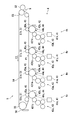
- FIG. 1 is a diagram illustrating a configuration of an image forming apparatus 1 according to the present embodiment.
- the image forming apparatus 1 is a color copying machine.
- the image forming apparatus 1 is an apparatus that forms an image on a sheet P, and includes a housing 10, a paper feeding unit 2, a transport unit L, a toner supply unit 3, an image forming unit 4, a transfer Section 5, fixing section 6, discharge section 7, and manual sheet feeding section 8.
- the paper feeding unit 2 is disposed at the bottom of the housing 10 and supplies the paper P to the transport unit L.
- the paper feed unit 2 can accommodate a plurality of sheets P, and supplies the uppermost sheet P one by one to the transport unit L.
- the transport unit L transports the paper P supplied by the paper feed unit 2 to the discharge unit 7 via the transfer unit 5 and the fixing unit 6.
- the toner supply unit 3 is a container that supplies toner to the image forming unit 4 and includes four toner cartridges 3c, 3m, 3y, and 3k.
- the toner cartridge 3c contains cyan toner.
- the toner cartridge 3m contains magenta toner.
- the toner cartridge 3y contains yellow toner.
- the toner cartridge 3k contains black toner.
- the toner cartridges 3c, 3m, and 3y may be referred to as a color toner cartridge 31, and the toner cartridge 3k may be referred to as a black toner cartridge 32.
- the transfer unit 5 includes an intermediate transfer belt 54.
- the transfer unit 5 transfers the toner image formed on the intermediate transfer belt 54 onto the paper P by the image forming unit 4.
- the configuration of the transfer unit 5 will be described later with reference to FIG.
- the transfer unit 5 corresponds to a part of the “image forming unit”.
- the image forming unit 4 forms a toner image on the intermediate transfer belt 54.
- the color toner and the black toner are supplied to the image forming unit 4 from the color toner cartridge 31 and the black toner cartridge 32, respectively.
- the image forming unit 4 includes four image forming units 4c, 4m, 4y, and 4k. Cyan toner is supplied from the toner cartridge 3c to the image forming unit 4c. Magenta toner is supplied from the toner cartridge 3m to the image forming unit 4m. Yellow toner is supplied from the toner cartridge 3y to the image forming unit 4y. Black toner is supplied to the image forming unit 4k from the toner cartridge 3k.
- the configuration of the image forming unit 4 will be described later with reference to FIG.
- the fixing unit 6 fixes the toner image formed on the paper P by the transfer unit 5 onto the paper P.
- the fixing unit 6 includes a heating roller 61 and a pressure roller 62.
- the paper P is heated and pressed by the heating roller 61 and the pressure roller 62.
- the fixing unit 6 corresponds to a part of the “image forming unit”.
- the discharge unit 7 discharges the paper P on which the toner image is fixed to the outside of the apparatus.
- the manual paper feed unit 8 includes a manual feed tray 81 and a paper feed roller 821.
- the paper P is placed on the manual feed tray 81 by the user.
- the paper feed roller 821 supplies the paper P placed on the manual feed tray 81 to the transport unit L.
- the paper P supplied by the paper feed roller 821 is transported by the transport unit L to the discharge unit 7 via the transfer unit 5 and the fixing unit 6.
- the manual paper feed unit 8 corresponds to a “manual paper feed mechanism”.
- FIG. 2 is a side view showing the configuration of the image forming unit 4 and the transfer unit 5.
- the image forming units 4c, 4m, 4y, and 4k each include an exposure device 41, a photosensitive drum 42, a developing unit 43, a charging roller 44, and a cleaning unit 45.
- the configuration of the four image forming units 4c, 4m, 4y, and 4k is substantially the same. Therefore, in this specification, the configuration of the image forming unit 4c to which cyan toner is supplied will be described, and the description of the configuration of the image forming units 4m, 4y, and 4k other than the image forming unit 4c will be omitted.
- the image forming unit 4c includes an exposure unit 41c (41), a photosensitive drum 42c (42), a developing unit 43c (43), a charging roller 44c (44), and a cleaning unit 45c (45).
- the charging roller 44c charges the photosensitive drum 42c to a predetermined potential.
- the exposure unit 41c irradiates the photosensitive drum 42c with laser light to form an electrostatic latent image on the photosensitive drum 42c.
- the developing unit 43c has a developing roller 431c.
- the developing roller 431c develops the electrostatic latent image by supplying cyan toner to the photosensitive drum 42c to form a toner image. In this way, a cyan toner image is formed on the peripheral surface of the photosensitive drum 42c.
- the cleaning unit 45c removes cyan toner remaining on the peripheral surface of the photosensitive drum 42c.
- the transfer unit 5 transfers the toner image onto the paper P (see FIG. 1).
- the transfer unit 5 includes four primary transfer rollers 51 (51c, 51m, 51y, 51k), a secondary transfer roller 52, a driving roller 53, an intermediate transfer belt 54, and a driven roller 55.
- the transfer unit 5 superimposes the toner images formed on the photosensitive drums 42 (42c, 42m, 42y, and 42k) of the image forming units 4c, 4m, 4y, and 4k on the intermediate transfer belt 54 after overlapping them.
- the toner image thus transferred is transferred from the intermediate transfer belt 54 to the paper P (see FIG. 1).
- the primary transfer roller 51c is disposed to face the photosensitive drum 42c with the intermediate transfer belt 54 interposed therebetween.
- the primary transfer roller 51c can be pressed against the photosensitive drum 42c via the intermediate transfer belt 54 or can be separated from the photosensitive drum 42c by a driving mechanism (not shown).
- the primary transfer roller 51 c is normally pressed against the photosensitive drum 42 c via the intermediate transfer belt 54.
- the other primary transfer rollers 51m, 51y, 51k are also in pressure contact with the corresponding photosensitive drums 42 (42m, 42y, or 42k) via the intermediate transfer belt 54, similarly to the primary transfer roller 51c.
- the driving roller 53 is disposed to face the secondary transfer roller 52 and drives the intermediate transfer belt 54.
- the intermediate transfer belt 54 is an endless belt stretched around four primary transfer rollers 51, a drive roller 53, and a driven roller 55.
- the intermediate transfer belt 54 is driven to rotate counterclockwise by the driving roller 53 as shown by arrows F1 and F2 in FIG. Further, the surface side of the intermediate transfer belt 54 is in contact with the peripheral surface of each photosensitive drum 42 (42c, 42m, 42y, 42k).
- a toner image is transferred from the photosensitive drum 42 (42c, 42m, 42y, 42k) to the surface of the intermediate transfer belt 54 by a primary transfer roller 51 (51c, 51m, 51y, 51k).
- the driven roller 55 is driven to rotate as the intermediate transfer belt 54 rotates.
- a blade 56 is disposed at a position facing the driven roller 55 via the intermediate transfer belt 54. The blade 56 removes toner remaining on the surface of the intermediate transfer belt 54.
- the secondary transfer roller 52 is pressed by the drive roller 53. As a result, a nip N is formed between the secondary transfer roller 52 and the drive roller 53.
- the secondary transfer roller 52 and the driving roller 53 transfer the toner image on the intermediate transfer belt 54 to the paper P (see FIG. 1) when the paper P passes through the nip portion N.
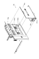
- FIG. 3 is an exploded perspective view showing a configuration of a conventional manual sheet feeder 8a.
- the manual paper feed unit 8a includes a manual feed tray 81a, a manual paper feed unit 82a, and an exterior unit 83a.
- the paper P is placed on the manual feed tray 81a by the user.
- the manual paper feed unit 82a includes an unillustrated paper feed roller and a separating roller, and supplies the paper P placed on the manual tray 81a to the transport unit L (see FIG. 1).
- the lower end portion of the manual feed tray 81a is rotatably engaged with the manual feed unit 82a.
- FIG. 3 shows the position of the manual feed tray 81a when the manual paper feed unit 8a is not in use.
- the manual tray 81a is in an upright state and functions as a part of the exterior surface.
- the manual feed tray 81a is rotated approximately 90 degrees clockwise with the lower end of the manual feed tray 81a as a fulcrum, and is in a substantially horizontal state.
- the exterior unit 83a constitutes a part of the housing 10 shown in FIG. 1 (the right side surface in FIG. 1).
- the exterior unit 83a includes a tray storage portion 831a and a unit storage portion 832a.
- the tray storage unit 831a stores the manual feed tray 81a.
- the unit storage unit 832a stores the manual paper feed unit 82a.
- the manual paper feed unit 82a can supply the paper P placed on the manual tray 81a to the transport unit L shown in FIG. 1 while being stored in the unit storage unit 832a.
- a manual paper feed unit 82a is configured by housing members such as a paper feed roller and a separating roller constituting a manual paper feed mechanism in one casing.
- the manual paper feed unit 82 a is disposed in the image forming apparatus 1 at a position facing the manual feed tray. Therefore, since the space for arranging the manual paper feed unit 82a is occupied in the image forming apparatus 1, there is room for improvement from the viewpoint of space saving in the vicinity of the manual paper feed mechanism.
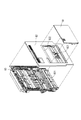
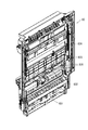
- FIG. 4 is an exploded perspective view showing the configuration of the manual sheet feeder 8.
- the manual sheet feeder 8 includes a manual tray 81, an exterior unit 82, and a conveyance guide unit 83.
- the paper P is placed on the manual feed tray 81 by the user.
- the exterior unit 82 is disposed to face the conveyance guide unit 83 and constitutes the conveyance unit L (see FIG. 1) and also constitutes a part of the exterior surface of the housing 10 (a part of the right side surface in FIG. 1). To do.
- the exterior unit 82 includes a paper feed roller 821 and a tray storage unit 822.
- the paper feed roller 821 is rotationally driven by a motor (not shown), and supplies the paper P placed on the manual feed tray 81 to the transport unit L shown in FIG. Further, the paper feed roller 821 is formed at a position corresponding to the central portion in the width direction of the paper P.
- the width of the paper feed roller 821 is narrower than the width of the paper P.
- the tray storage unit 822 stores the manual feed tray 81.
- FIG. 4 shows the position of the manual feed tray 81 when the manual feed unit 8 is not in use.
- the manual tray 81 is in an upright state and functions as a part of the exterior surface.
- the manual feed tray 81 is rotated approximately 90 degrees clockwise with the lower end of the manual feed tray 81 as a fulcrum, and is in a substantially horizontal state.
- the conveyance guide unit 83 constitutes a conveyance unit L (see FIG. 1) that conveys the paper P. Further, the transport guide unit 83 includes a retard roller 831.
- the retard roller 831 is arranged so that two or more sheets of paper P fed by the paper feed roller 821 are not overlapped and conveyed. Further, the retard roller 831 is formed at a position corresponding to the central portion in the width direction of the paper P. The width of the retard roller 831 is narrower than the width of the paper P.
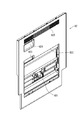
- FIG. 5 is a perspective view showing the configuration of the exterior unit 82.
- the exterior unit 82 includes a recess 823, a handle 824, and an opening 825 in addition to the paper feed roller 821 and the tray storage unit 822.
- the concave portion 823 is formed on the upper side of the tray storage portion 822, and a user's hand is inserted when the manual feed tray 81 is changed from the non-use state (upright state) to the use state (horizontal state). For example, when a jam occurs between the exterior unit 82 and the transport guide unit 83, the handle 824 is inserted by a user's hand to open the exterior unit 82 with respect to the transport guide unit 83. .
- the exterior unit 82 is configured to be rotatable about the right end portion of the exterior unit 82 as a fulcrum.
- the opening 825 allows air to flow into the housing 10 (see FIG. 1) from the outside and exhausts the air inside the housing 10 to the outside.
- FIG. 6 is a perspective view showing the configuration of the transport guide unit 83.
- the transport guide unit 83 further includes transport rollers 832, 833, and 834, and a transport guide 835.
- the transport rollers 832, 833, and 834 are disposed in the transport unit L (see FIG. 1) and transport the paper P.
- transport rollers are arranged at positions facing the transport rollers 832, 833, and 834 of the transport guide unit 83.
- the conveyance guide 835 guides conveyance of the paper P between the conveyance roller 832 and the conveyance roller 833.
- the transport guide 835 is a plate-like member that is erected on the casing that configures the transport guide unit 83 along the transport direction of the paper P (the vertical direction in FIG. 6).
- a plurality of conveyance guides 835 are arranged in the width direction (left-right direction in FIG. 6).
- a transport guide is disposed at a position facing the transport guide 835 of the transport guide unit 83.
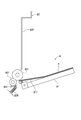
- FIG. 7 is a side view illustrating a configuration of a main part of the manual sheet feeder 8.
- the manual feed tray 81 includes a lifting plate 811.
- the elevating plate 811 is driven by a motor (not shown) and rises during paper feeding to press the uppermost paper among the papers P against the paper feeding roller 821.
- the conveyance guide unit 83 is further provided with a spring 836 and a pressing member 837.
- the spring 836 presses the retard roller 831 against the paper feed roller 821 via the pressing member 837.
- the paper feed roller 821 is always driven to rotate by a motor (not shown).
- the retard roller 831 normally rotates in the direction opposite to the rotation direction of the paper feed roller 821, and rotates in the forward direction according to a load applied to a torque limiter (not shown).
- the members (feed roller 821, retard roller 831, spring 836, and pressing member 837) constituting the manual sheet feeding mechanism that performs manual sheet feeding are arranged in the transport guide unit 83 or the exterior unit 82. Therefore, space saving in the vicinity of the manual sheet feeding mechanism can be achieved.
- the members constituting the manual paper feed unit 8 include a paper feed roller 821 that feeds paper from the manual feed tray 81 to the transport unit L, and the paper feed roller 821 is disposed in the exterior unit 82. Therefore, it is possible to save space in the vicinity of the manual sheet feeding mechanism with a simple configuration.
- the paper feed roller 821 is formed at a position corresponding to the central portion in the width direction of the paper P. Further, the width of the paper feed roller 821 is narrower than the width of the paper P. Therefore, it is possible to further save the space near the manual sheet feeding mechanism with a simple configuration.
- the members constituting the manual paper feed unit 8 include a retard roller 831 that rolls the paper P.
- the retard roller 831 is disposed in the transport guide unit 83. Therefore, it is possible to save space in the vicinity of the manual sheet feeding mechanism with a simple configuration.
- the retard roller 831 is formed at a position corresponding to the central portion in the width direction of the paper P.
- the width of the retard roller 831 is narrower than the width of the paper P. Therefore, it is possible to further save the space near the manual sheet feeding mechanism with a simple configuration.
- the present invention can be used for an image forming apparatus.
Landscapes
- Engineering & Computer Science (AREA)
- Mechanical Engineering (AREA)
- Physics & Mathematics (AREA)
- General Physics & Mathematics (AREA)
- Manual Feeding Of Sheets (AREA)
- Sheets, Magazines, And Separation Thereof (AREA)
- Paper Feeding For Electrophotography (AREA)
- Electrophotography Configuration And Component (AREA)
Abstract
Description
Claims (9)
- 記録媒体に画像を形成する画像形成装置であって、
前記記録媒体に画像を形成する画像形成部と、
前記記録媒体を搬送する搬送部と、
手差し給紙を行う手差し給紙機構と
を備え、
前記搬送部の一部は、搬送ガイドユニットと外装ユニットとによって構成され、
前記外装ユニットは、前記搬送ガイドユニットに対向して配置され、前記画像形成装置の外装面の一部を構成し、
前記手差し給紙機構は、前記搬送ガイドユニット又は前記外装ユニットに配置されている、画像形成装置。 - 前記手差し給紙機構を構成する部材は、前記記録媒体を前記搬送部に給紙する給紙ローラーを含み、
前記給紙ローラーは、前記外装ユニットに配置される、請求項1に記載の画像形成装置。 - 前記給紙ローラーは、前記記録媒体の幅方向中央部に対応する位置に形成され、
前記給紙ローラーの幅は、前記記録媒体の幅よりも狭い、請求項2に記載の画像形成装置。 - 前記手差し給紙機構を構成する部材は、前記給紙ローラーによって給紙された前記記録媒体を捌く捌きローラーを含み、
前記捌きローラーは、前記搬送ガイドユニットに配置される、請求項2に記載の画像形成装置。 - 前記捌きローラーは、前記記録媒体の幅方向中央部に対応する位置に形成され、
前記捌きローラーの幅は、前記記録媒体の幅よりも狭い、請求項4に記載の画像形成装置。 - 前記捌きローラーは、リタードローラーである、請求項4に記載の画像形成装置。
- 前記手差し給紙機構を構成する部材は、前記給紙ローラーによって給紙された前記記録媒体を捌く捌きローラーを含み、
前記捌きローラーは、前記外装ユニットに配置される、請求項2に記載の画像形成装置。 - 前記手差し給紙機構を構成する部材は、前記記録媒体が載置される手差しトレイを含み、
前記外装ユニットは、トレイ収納部を備え、
前記トレイ収納部は、前記手差しトレイを収納する、請求項2に記載の画像形成装置。 - 前記手差しトレイは、昇降板を備え、
前記昇降板は、給紙時に、前記手差しトレイに載置された前記記録媒体を前記給紙ローラーに圧接する、請求項8に記載の画像形成装置。
Priority Applications (2)
| Application Number | Priority Date | Filing Date | Title |
|---|---|---|---|
| JP2017510953A JP6451834B2 (ja) | 2015-04-06 | 2016-03-31 | 画像形成装置 |
| US15/550,906 US10035671B2 (en) | 2015-04-06 | 2016-03-31 | Image forming apparatus |
Applications Claiming Priority (2)
| Application Number | Priority Date | Filing Date | Title |
|---|---|---|---|
| JP2015077796 | 2015-04-06 | ||
| JP2015-077796 | 2015-04-06 |
Publications (1)
| Publication Number | Publication Date |
|---|---|
| WO2016163298A1 true WO2016163298A1 (ja) | 2016-10-13 |
Family
ID=57072443
Family Applications (1)
| Application Number | Title | Priority Date | Filing Date |
|---|---|---|---|
| PCT/JP2016/060640 Ceased WO2016163298A1 (ja) | 2015-04-06 | 2016-03-31 | 画像形成装置 |
Country Status (3)
| Country | Link |
|---|---|
| US (1) | US10035671B2 (ja) |
| JP (1) | JP6451834B2 (ja) |
| WO (1) | WO2016163298A1 (ja) |
Citations (4)
| Publication number | Priority date | Publication date | Assignee | Title |
|---|---|---|---|---|
| JPH07133044A (ja) * | 1993-11-11 | 1995-05-23 | Ricoh Co Ltd | 給紙装置 |
| JP2005138970A (ja) * | 2003-11-07 | 2005-06-02 | Murata Mach Ltd | 両面画像形成装置の反転搬送路 |
| JP2005350264A (ja) * | 2004-05-14 | 2005-12-22 | Oki Data Corp | 媒体供給装置及び画像形成装置 |
| JP2009155071A (ja) * | 2007-12-27 | 2009-07-16 | Canon Inc | シート処理装置 |
Family Cites Families (4)
| Publication number | Priority date | Publication date | Assignee | Title |
|---|---|---|---|---|
| JP2013086968A (ja) | 2011-10-24 | 2013-05-13 | Konica Minolta Business Technologies Inc | 画像形成装置 |
| KR20150026597A (ko) * | 2013-09-03 | 2015-03-11 | 삼성전자주식회사 | 인쇄매체공급장치 및 이를 갖는 화상형성장치 |
| KR102047904B1 (ko) * | 2013-09-26 | 2019-11-22 | 휴렛-팩커드 디벨롭먼트 컴퍼니, 엘.피. | 인쇄매체공급장치 및 이를 갖는 화상형성장치 |
| JP2015089850A (ja) * | 2013-11-07 | 2015-05-11 | 株式会社リコー | シート載置トレイ、シート給送装置及び画像形成装置 |
-
2016
- 2016-03-31 JP JP2017510953A patent/JP6451834B2/ja active Active
- 2016-03-31 US US15/550,906 patent/US10035671B2/en active Active
- 2016-03-31 WO PCT/JP2016/060640 patent/WO2016163298A1/ja not_active Ceased
Patent Citations (4)
| Publication number | Priority date | Publication date | Assignee | Title |
|---|---|---|---|---|
| JPH07133044A (ja) * | 1993-11-11 | 1995-05-23 | Ricoh Co Ltd | 給紙装置 |
| JP2005138970A (ja) * | 2003-11-07 | 2005-06-02 | Murata Mach Ltd | 両面画像形成装置の反転搬送路 |
| JP2005350264A (ja) * | 2004-05-14 | 2005-12-22 | Oki Data Corp | 媒体供給装置及び画像形成装置 |
| JP2009155071A (ja) * | 2007-12-27 | 2009-07-16 | Canon Inc | シート処理装置 |
Also Published As
| Publication number | Publication date |
|---|---|
| JPWO2016163298A1 (ja) | 2017-11-09 |
| US10035671B2 (en) | 2018-07-31 |
| JP6451834B2 (ja) | 2019-01-16 |
| US20180029812A1 (en) | 2018-02-01 |
Similar Documents
| Publication | Publication Date | Title |
|---|---|---|
| US10040652B2 (en) | Sheet feeding apparatus, sheet conveyance apparatus, and image forming apparatus | |
| JP2012126554A (ja) | 搬送装置及び画像形成装置 | |
| JP6468819B2 (ja) | 画像形成装置 | |
| JP6233245B2 (ja) | シート排出装置、およびこれを備えた画像形成装置 | |
| JP2009227437A (ja) | バネ取付構造、及び画像形成装置 | |
| JP6323377B2 (ja) | シート搬送装置、およびこれを備えた画像形成装置 | |
| CN102023535B (zh) | 转印装置和图像形成装置 | |
| JP6451834B2 (ja) | 画像形成装置 | |
| JP5549312B2 (ja) | 定着装置、片面用画像形成装置及び両面用画像形成装置 | |
| JP2017161652A (ja) | 着脱装置及び画像形成装置 | |
| JP2017003819A (ja) | 画像形成装置 | |
| JP6268462B2 (ja) | シート材給送装置、画像形成装置 | |
| JP2018141876A (ja) | 画像形成装置 | |
| JP2010256809A (ja) | 画像形成装置 | |
| JP4831249B2 (ja) | 画像形成装置 | |
| JP6291980B2 (ja) | 給紙カセット、及び、画像形成装置 | |
| JP5027897B2 (ja) | 感光体ドラム支持構造及びこれを備えた画像形成装置 | |
| JP5895608B2 (ja) | 用紙搬送装置、および画像形成装置 | |
| JP5292867B2 (ja) | 画像形成装置 | |
| JP6668927B2 (ja) | シート材給送装置及び画像形成装置 | |
| JP4563963B2 (ja) | 用紙搬送装置、画像形成装置 | |
| JP2006048004A (ja) | 画像形成装置 | |
| JP6828289B2 (ja) | シート搬送装置 | |
| JP5935727B2 (ja) | シート材の搬送路及び画像形成装置 | |
| JP6958000B2 (ja) | 駆動装置および画像形成装置 |
Legal Events
| Date | Code | Title | Description |
|---|---|---|---|
| 121 | Ep: the epo has been informed by wipo that ep was designated in this application |
Ref document number: 16776465 Country of ref document: EP Kind code of ref document: A1 |
|
| ENP | Entry into the national phase |
Ref document number: 2017510953 Country of ref document: JP Kind code of ref document: A |
|
| WWE | Wipo information: entry into national phase |
Ref document number: 15550906 Country of ref document: US |
|
| NENP | Non-entry into the national phase |
Ref country code: DE |
|
| 122 | Ep: pct application non-entry in european phase |
Ref document number: 16776465 Country of ref document: EP Kind code of ref document: A1 |