WO2016163149A1 - 燃料電池システム及びその制御方法 - Google Patents
燃料電池システム及びその制御方法 Download PDFInfo
- Publication number
- WO2016163149A1 WO2016163149A1 PCT/JP2016/054169 JP2016054169W WO2016163149A1 WO 2016163149 A1 WO2016163149 A1 WO 2016163149A1 JP 2016054169 W JP2016054169 W JP 2016054169W WO 2016163149 A1 WO2016163149 A1 WO 2016163149A1
- Authority
- WO
- WIPO (PCT)
- Prior art keywords
- cooling water
- stack
- passage
- radiator
- bypass
- Prior art date
- Legal status (The legal status is an assumption and is not a legal conclusion. Google has not performed a legal analysis and makes no representation as to the accuracy of the status listed.)
- Ceased
Links
Images









Classifications
-
- H—ELECTRICITY
- H01—ELECTRIC ELEMENTS
- H01M—PROCESSES OR MEANS, e.g. BATTERIES, FOR THE DIRECT CONVERSION OF CHEMICAL ENERGY INTO ELECTRICAL ENERGY
- H01M8/00—Fuel cells; Manufacture thereof
- H01M8/04—Auxiliary arrangements, e.g. for control of pressure or for circulation of fluids
- H01M8/04298—Processes for controlling fuel cells or fuel cell systems
- H01M8/043—Processes for controlling fuel cells or fuel cell systems applied during specific periods
- H01M8/04302—Processes for controlling fuel cells or fuel cell systems applied during specific periods applied during start-up
-
- H—ELECTRICITY
- H01—ELECTRIC ELEMENTS
- H01M—PROCESSES OR MEANS, e.g. BATTERIES, FOR THE DIRECT CONVERSION OF CHEMICAL ENERGY INTO ELECTRICAL ENERGY
- H01M8/00—Fuel cells; Manufacture thereof
- H01M8/04—Auxiliary arrangements, e.g. for control of pressure or for circulation of fluids
- H01M8/04007—Auxiliary arrangements, e.g. for control of pressure or for circulation of fluids related to heat exchange
- H01M8/04029—Heat exchange using liquids
-
- H—ELECTRICITY
- H01—ELECTRIC ELEMENTS
- H01M—PROCESSES OR MEANS, e.g. BATTERIES, FOR THE DIRECT CONVERSION OF CHEMICAL ENERGY INTO ELECTRICAL ENERGY
- H01M8/00—Fuel cells; Manufacture thereof
- H01M8/04—Auxiliary arrangements, e.g. for control of pressure or for circulation of fluids
- H01M8/04007—Auxiliary arrangements, e.g. for control of pressure or for circulation of fluids related to heat exchange
- H01M8/04067—Heat exchange or temperature measuring elements, thermal insulation, e.g. heat pipes, heat pumps, fins
- H01M8/04074—Heat exchange unit structures specially adapted for fuel cell
-
- H—ELECTRICITY
- H01—ELECTRIC ELEMENTS
- H01M—PROCESSES OR MEANS, e.g. BATTERIES, FOR THE DIRECT CONVERSION OF CHEMICAL ENERGY INTO ELECTRICAL ENERGY
- H01M8/00—Fuel cells; Manufacture thereof
- H01M8/04—Auxiliary arrangements, e.g. for control of pressure or for circulation of fluids
- H01M8/04223—Auxiliary arrangements, e.g. for control of pressure or for circulation of fluids during start-up or shut-down; Depolarisation or activation, e.g. purging; Means for short-circuiting defective fuel cells
- H01M8/04225—Auxiliary arrangements, e.g. for control of pressure or for circulation of fluids during start-up or shut-down; Depolarisation or activation, e.g. purging; Means for short-circuiting defective fuel cells during start-up
-
- H—ELECTRICITY
- H01—ELECTRIC ELEMENTS
- H01M—PROCESSES OR MEANS, e.g. BATTERIES, FOR THE DIRECT CONVERSION OF CHEMICAL ENERGY INTO ELECTRICAL ENERGY
- H01M8/00—Fuel cells; Manufacture thereof
- H01M8/04—Auxiliary arrangements, e.g. for control of pressure or for circulation of fluids
- H01M8/04298—Processes for controlling fuel cells or fuel cell systems
- H01M8/04313—Processes for controlling fuel cells or fuel cell systems characterised by the detection or assessment of variables; characterised by the detection or assessment of failure or abnormal function
- H01M8/04537—Electric variables
- H01M8/04634—Other electric variables, e.g. resistance or impedance
- H01M8/04656—Other electric variables, e.g. resistance or impedance of auxiliary devices, e.g. batteries, capacitors
-
- H—ELECTRICITY
- H01—ELECTRIC ELEMENTS
- H01M—PROCESSES OR MEANS, e.g. BATTERIES, FOR THE DIRECT CONVERSION OF CHEMICAL ENERGY INTO ELECTRICAL ENERGY
- H01M8/00—Fuel cells; Manufacture thereof
- H01M8/10—Fuel cells with solid electrolytes
- H01M2008/1095—Fuel cells with polymeric electrolytes
-
- H—ELECTRICITY
- H01—ELECTRIC ELEMENTS
- H01M—PROCESSES OR MEANS, e.g. BATTERIES, FOR THE DIRECT CONVERSION OF CHEMICAL ENERGY INTO ELECTRICAL ENERGY
- H01M2250/00—Fuel cells for particular applications; Specific features of fuel cell system
- H01M2250/20—Fuel cells in motive systems, e.g. vehicle, ship, plane
-
- Y—GENERAL TAGGING OF NEW TECHNOLOGICAL DEVELOPMENTS; GENERAL TAGGING OF CROSS-SECTIONAL TECHNOLOGIES SPANNING OVER SEVERAL SECTIONS OF THE IPC; TECHNICAL SUBJECTS COVERED BY FORMER USPC CROSS-REFERENCE ART COLLECTIONS [XRACs] AND DIGESTS
- Y02—TECHNOLOGIES OR APPLICATIONS FOR MITIGATION OR ADAPTATION AGAINST CLIMATE CHANGE
- Y02E—REDUCTION OF GREENHOUSE GAS [GHG] EMISSIONS, RELATED TO ENERGY GENERATION, TRANSMISSION OR DISTRIBUTION
- Y02E60/00—Enabling technologies; Technologies with a potential or indirect contribution to GHG emissions mitigation
- Y02E60/30—Hydrogen technology
- Y02E60/50—Fuel cells
-
- Y—GENERAL TAGGING OF NEW TECHNOLOGICAL DEVELOPMENTS; GENERAL TAGGING OF CROSS-SECTIONAL TECHNOLOGIES SPANNING OVER SEVERAL SECTIONS OF THE IPC; TECHNICAL SUBJECTS COVERED BY FORMER USPC CROSS-REFERENCE ART COLLECTIONS [XRACs] AND DIGESTS
- Y02—TECHNOLOGIES OR APPLICATIONS FOR MITIGATION OR ADAPTATION AGAINST CLIMATE CHANGE
- Y02T—CLIMATE CHANGE MITIGATION TECHNOLOGIES RELATED TO TRANSPORTATION
- Y02T90/00—Enabling technologies or technologies with a potential or indirect contribution to GHG emissions mitigation
- Y02T90/40—Application of hydrogen technology to transportation, e.g. using fuel cells
Definitions
- the present invention relates to a fuel cell system and a control method thereof.
- a fuel cell stack configured to generate electric power through an electrochemical reaction between hydrogen gas and air, a radiator configured to reduce the temperature of cooling water for the fuel cell stack, and cooling in the radiator within the radiator
- a cooling water supply passage that connects the outlet of the water passage and the inlet of the cooling water passage in the stack in the fuel cell stack to each other between the supply side branch point and the outlet of the cooling water passage in the radiator to the supply side branch point.
- a cooling water supply passage comprising a radiator outflow passage, a stack inflow passage from the supply-side branch point to the inlet of the cooling water passage in the stack, and the outlet of the cooling water passage in the stack and the inlet of the cooling water passage in the radiator.
- a cooling water discharge passage having a radiator inflow path from a point to an inlet of the cooling water passage in the radiator, and a bypass cooling water passage connecting the supply side branch point and the discharge side branch point to each other, and ions in the cooling water
- a bypass cooling water passage having an ion remover configured to remove water, a cooling water pump disposed in the radiator outlet passage so that the inlet faces the radiator, and cooling water flowing through the bypass cooling water passage
- a bypass cooling water control valve that controls the amount of the cooling water, and drives the cooling water pump and controls the bypass cooling water control valve, whereby a part of the cooling water that circulates in the radiator outlet passage is bypassed.
- a fuel cell system is known in which the inside of the fuel cell stack is circulated through the inside of the cooling water passage of the fuel cell stack (see, for example, Patent Document 1). ). Ions elute from the radiator or the like in the cooling water, and as a result, the conductivity of the cooling water increases. However, when cooling water having an excessively high conductivity flows into the fuel cell stack, the electrical insulation of the fuel cell stack may be reduced. In the fuel cell system of Patent Document 1, since a part of the cooling water always circulates in the ion remover, the conductivity of the cooling water is lowered, thereby suppressing the electric insulation of the fuel cell stack from being lowered. The In the fuel cell system disclosed in Patent Document 1, the remaining cooling water always circulates in the fuel cell stack.
- a fuel cell stack configured to generate electric power by an electrochemical reaction between a fuel gas and an oxidant gas, and a cooling water temperature for the fuel cell stack are lowered.
- a configured radiator, a cooling water supply passage for connecting an outlet of the cooling water passage in the radiator in the radiator and an inlet of the cooling water passage in the stack in the fuel cell stack, and the cooling water passage in the stack A cooling water discharge passage for connecting an outlet and an inlet of the cooling water passage in the radiator to each other, wherein the cooling water supply passage includes a supply side branch point and an outlet of the cooling water passage in the radiator to the supply side branch point And a stack inflow passage from the supply-side branch point to the inlet of the cooling water passage in the stack, and the cooling water discharge passage A side branch point, a stack outflow passage from the outlet of the cooling water passage in the stack to the discharge side branch point, and a radiator inflow passage from the discharge side branch point to the inlet of the cooling water passage in the radiator,
- a radiator side cooling water pump disposed in the radiator outflow passage so that an inlet faces the radiator, and is configured to control the amount of cooling water flowing in the bypass cooling water passage
- the bypass cooling water control valve, the radiator side cooling water pump, and the bypass cooling water control valve are respectively controlled, whereby a stack circulation mode in which the cooling water flows at least in the stack side cooling water passage, and the cooling water
- a controller configured to selectively perform any one of a stack bypass mode in which the inside of the bypass cooling water passage is circulated with little flow in the stack side cooling water passage.
- a fuel cell stack configured to generate electric power by an electrochemical reaction between a fuel gas and an oxidant gas, and a cooling water temperature for the fuel cell stack are lowered.
- a radiator configured in the above, a cooling water supply passage that connects an outlet of the cooling water passage in the radiator in the radiator and an inlet of the cooling water passage in the stack in the fuel cell stack, and the cooling water passage in the stack A cooling water discharge passage that connects the outlet of the cooling water passage and the inlet of the cooling water passage in the radiator to each other, wherein the cooling water supply passage is connected to the supply side branch point and the supply side branch from the outlet of the cooling water passage in the radiator A radiator outflow passage to a point, and a stack inflow passage from the supply-side branch point to an inlet of the cooling water passage in the stack, the cooling water discharge passage, An outlet branch point, a stack outflow passage from the outlet of the cooling water passage in the stack to the discharge branch point, and a radiator inflow passage from the discharge branch point to the inlet
- the stack inflow passage, the stack cooling water passage, and the stack outflow passage constitute a stack side cooling water passage, and the radiator inflow passage, the radiator internal cooling water passage, and the radiator outflow passage form a radiator side cooling water.
- a bypass cooling water passage connecting the cooling water supply passage and the cooling water discharge passage, and the supply side branch point and the discharge side branch point to each other so as to remove ions in the cooling water.
- a bypass cooling water passage having a configured ion remover, and in the radiator inflow passage so that an outlet faces the radiator.
- a radiator-side cooling water pump disposed in the radiator outlet passage so that the inlet faces the radiator or the amount of the cooling water flowing through the bypass cooling water passage is controlled.
- a control method for a fuel cell system comprising: a bypass cooling water control valve; and a controller configured to control each of the radiator side cooling water pump and the bypass cooling water control valve, wherein the radiator side cooling The water pump and the bypass cooling water control valve are controlled by the controller, respectively, so that the cooling water flows at least in the stack side cooling water passage, and the cooling water is in the stack side cooling water passage. Select one of the stack bypass modes that circulate in the bypass cooling water passage with almost no circulation.
- a method of controlling a fuel cell system is provided that is configured to perform automatically.
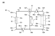
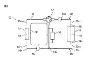
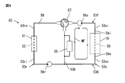
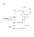
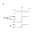
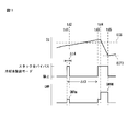
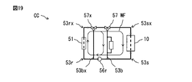
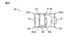
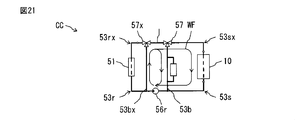
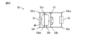
- FIG. 1 is an overall view of a fuel cell system. It is a schematic diagram of a cooling circuit. It is a schematic diagram of the cooling circuit explaining the stack full bypass mode. It is a schematic diagram of the cooling circuit explaining a radiator all bypass mode. It is a schematic diagram of the cooling circuit explaining a radiator partial bypass mode. It is a schematic diagram of the cooling circuit explaining bypassless mode. It is a mimetic diagram of a cooling circuit explaining stack partial bypass mode. It is a time chart explaining start control. It is a time chart explaining start control. 4 is a time chart for explaining cooling water control after a signal to start power generation in the fuel cell stack 10 is issued.
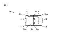
- 4 is a time chart for explaining cooling water control during power generation stoppage in the fuel cell stack 10; 4 is a flowchart for executing cooling water control while power generation is stopped in the fuel cell stack 10; 4 is a flowchart for executing cooling water control after a signal to start power generation in the fuel cell stack 10 is issued. It is a flowchart for performing start control. It is a flowchart for performing power generation control. It is a schematic diagram of the cooling circuit of another Example by this invention. It is a schematic diagram of the cooling circuit of another Example by this invention. It is a schematic diagram of the cooling circuit explaining the bypassless mode in the Example shown by FIG. It is a schematic diagram of the cooling circuit explaining the stack
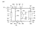
- FIG. 18 is a schematic diagram of a cooling circuit for explaining a radiator full bypass-stack partial mode in the embodiment shown in FIG. 17. It is a schematic diagram of the cooling circuit explaining the 2nd radiator partial bypass mode in the Example shown by FIG. FIG. 18 is a schematic diagram of a cooling circuit for explaining a radiator partial bypass-stack partial bypass mode in the embodiment shown in FIG. 17.
- FIG. 18 is a schematic diagram of a cooling circuit for explaining a stack full bypass mode in the embodiment shown in FIG. 17.
- FIG. 18 is a schematic diagram of a cooling circuit for explaining a stack full bypass-radiator full bypass mode in the embodiment shown in FIG. 17.
- the fuel cell system A includes a fuel cell stack 10.
- the fuel cell stack 10 includes a plurality of fuel cell single cells 10a stacked on each other along the stacking direction LS.
- Each fuel cell single cell 10 a includes a membrane electrode assembly 20.
- the membrane electrode assembly 20 includes a membrane electrolyte, an anode electrode formed on one side of the electrolyte, and a cathode electrode formed on the other side of the electrolyte.
- the anode electrode and the cathode electrode of the fuel cell single cell 10 a are electrically connected in series, respectively, and the outermost anode electrode and cathode electrode in the stacking direction LS constitute the electrode of the fuel cell stack 10.
- the electrode of the fuel cell stack 10 is electrically connected to the inverter 12 via the DC / DC converter 11, and the inverter 12 is electrically connected to the motor generator 13.
- the fuel cell system A includes a capacitor 14, and this capacitor 14 is electrically connected to the above-described inverter 12 via a DC / DC converter 15.
- the DC / DC converter 11 is for increasing the voltage from the fuel cell stack 10 and sending it to the inverter 12, and the inverter 12 is for converting the direct current from the DC / DC converter 11 or the capacitor 14 into an alternating current. It is.
- the DC / DC converter 15 is for reducing the voltage from the fuel cell stack 10 or the motor generator 13 to the battery 14 or increasing the voltage from the battery 14 to the motor generator 13.
- the battery 14 is composed of a battery.
- a hydrogen gas flow passage 30a for supplying hydrogen gas as fuel gas to the anode electrode, and an air flow passage 40a for supplying air as oxidant gas to the cathode electrode, are formed, and a cooling water flow passage 50a for supplying cooling water to the single fuel cell 10a is formed between the two adjacent single fuel cells 10a.
- the hydrogen gas flow passage 30a, the air flow passage 40a, and the cooling water flow passage 50a of the plurality of fuel cell single cells 10a are connected. Water passages 50 are respectively formed.
- the inlet and outlet of the hydrogen gas passage 30, the air passage 40, and the cooling water passage 50 are each arranged at one end of the fuel cell stack 10 in the stacking direction LS.
- the inlet of the hydrogen gas flow passage 30a and the outlet of the air flow passage 40a are the stack central axis.
- the outlet of the hydrogen gas flow passage 30a and the inlet of the air flow passage 40a are arranged on the other side of the stack center axis. Therefore, the direction of the hydrogen gas flowing through the hydrogen gas flow passage 30a and the direction of the air flowing through the air flow passage 40a are substantially opposite to each other. That is, the fuel cell stack 10 is composed of a countercurrent fuel cell stack.
- the inlet of the hydrogen gas flow passage 30a and the inlet of the air flow passage 40a are arranged on one side of the stack center axis, and the outlet of the hydrogen gas flow passage 30a and the outlet of the air flow passage 40a are the center of the stack. Arranged on the other side of the axis. Therefore, the direction of the hydrogen gas flowing in the hydrogen gas flow passage 30a and the direction of the air flowing in the air flow passage 40a are substantially the same. That is, in another embodiment (not shown), the fuel cell stack 10 is constituted by a cocurrent fuel cell stack.
- a hydrogen gas supply pipe 31 is connected to the inlet of the hydrogen gas passage 30, and the hydrogen gas supply pipe 31 is connected to a hydrogen gas source, for example, a hydrogen tank 32.
- a hydrogen gas source for example, a hydrogen tank 32.
- an electromagnetic shut-off valve 33, a regulator 34 for adjusting the pressure in the hydrogen gas supply pipe 31, and hydrogen gas from the hydrogen gas source 32 are supplied to the fuel cell stack 10.
- a hydrogen gas supply unit 35 for supply is arranged.
- the hydrogen gas supplier 35 is constituted by an electromagnetic hydrogen gas supply valve. This hydrogen gas supply valve includes a needle valve, and therefore hydrogen gas is intermittently supplied from the hydrogen gas supply valve.
- a purge pipe 37 is connected to the outlet of the hydrogen gas passage 30 through a buffer tank 36.
- An electromagnetic purge control valve 38 is disposed in the purge pipe 37.
- the shutoff valve 33 and the hydrogen gas supply valve 35 are opened, the hydrogen gas in the hydrogen tank 32 is supplied into the hydrogen gas passage 30 in the fuel cell stack 10 through the hydrogen gas supply pipe 31.
- the gas flowing out from the hydrogen gas passage 30, that is, the anode off-gas flows into the buffer tank 36 and is accumulated in the buffer tank 36.
- the purge control valve 38 is normally closed and is periodically opened over a short time. When the purge control valve 38 is opened, the anode off gas in the buffer tank 36 is discharged to the atmosphere via the purge pipe 37, that is, a purge process is performed.
- the outlet of the purge pipe 37 is communicated with the atmosphere. That is, the outlet of the hydrogen gas passage 30 is not communicated with the hydrogen gas supply pipe 31 and is therefore separated from the hydrogen gas supply pipe 31. This means that the anode off gas flowing out from the outlet of the hydrogen gas passage 30 is not returned to the hydrogen gas supply pipe 31.
- the fuel cell system A shown in FIG. 1 is a hydrogen gas non-circulation type.
- the outlet of the hydrogen gas passage 30 is connected to a hydrogen gas supply pipe 31 between, for example, the regulator 34 and the hydrogen gas supply valve 35 via a hydrogen gas return pipe.
- the fuel cell system A is a hydrogen gas circulation type.
- the hydrogen gas return pipe, the hydrogen gas return pump, and the like are omitted.
- the configuration is simplified, the cost is reduced, and a space for a hydrogen gas return pipe or the like is not required.
- an air supply pipe 41 is connected to the inlet of the air passage 40, and the air supply pipe 41 is connected to an air source, for example, the atmosphere 42.
- an air cleaner 43 In the air supply pipe 41, an air cleaner 43, a compressor 44 that pumps air and an intercooler 45 that cools the air sent from the compressor 44 to the fuel cell stack 10 are disposed in order from the upstream side.
- a cathode offgas pipe 46 is connected to the outlet of the air passage 40.
- an electromagnetic cathode pressure control valve 47 for controlling the cathode pressure, which is the pressure in the air passage 40, and a diluter 48 are arranged in order from the upstream side.
- the above-described purge pipe 37 is connected to the diluter 48.
- the hydrogen gas in the purge gas from the purge pipe 37 is diluted by the cathode off gas.
- a branch pipe 41 a branched from the air supply pipe 41 downstream of the intercooler 45 to the cathode offgas pipe 46 downstream of the cathode pressure control valve 47, and discharged from the compressor 44.
- a bypass control valve 41b for controlling the amount of air supplied to the fuel cell stack 10 and the amount of air flowing into the bypass pipe 41a is provided.
- the cooling circuit CC is connected to the inlet and outlet of the cooling water passage 50 in the fuel cell stack 10 described above.
- the cooling circuit CC includes a radiator 51 configured to reduce the temperature of the cooling water.
- a radiator cooling water passage 52 through which cooling water flows is formed in the radiator 51.
- the cooling water passage 50 in the fuel cell stack 10 is referred to as an in-stack cooling water passage
- the outlet 52o of the radiator cooling water passage 52 and the inlet 50i of the in-stack cooling water passage 50 are connected to each other by a cooling water supply passage 53f.
- the cooling water supply passage 53f includes a radiator outlet passage 53ro from the outlet 52o of the in-radiator cooling water passage 52 to the supply-side branch point 54f, and a stack inflow passage from the supply-side branch point 54f to the inlet 50i of the in-stack cooling water passage 50. 53si. Further, the outlet 50o of the in-stack cooling water passage 50 and the inlet 52i of the in-radiator cooling water passage 52 are connected to each other by a cooling water discharge passage 53d.
- the cooling water discharge passage 53d includes a stack outflow passage 53so from the outlet 50o of the in-stack cooling water passage 50 to the discharge side branch point 54d, and a radiator inflow passage from the discharge side branch point 54d to the inlet 52i of the cooling water passage 52 in the radiator. 53ri.
- the supply side branch point 54f of the cooling water supply passage 53f and the discharge side branch point 54d of the cooling water discharge passage 53d are connected to each other by a bypass cooling water passage 53b.
- the bypass cooling water passage 53b includes a branch passage 53bb that branches from the bypass cooling water passage 53b and returns to the bypass cooling water passage 53b, and is configured to remove ions in the cooling water in the branch passage 53bb.
- An ion remover 55 is arranged. Therefore, a part of the cooling water that has flowed into the bypass cooling water passage 53b circulates in the ion remover 55, and ions in the cooling water circulated in the ion remover 55 are removed.
- a check valve is not provided in the bypass cooling water passage 53b, so that the cooling water can bidirectionally flow between the supply side branch point 54f and the discharge side branch point 54d.
- a cooling water pump is not provided in the bypass cooling water passage 53b.
- the cooling circuit CC further includes two cooling water pumps, that is, a stack side cooling water pump 56s and a radiator side cooling water pump 56r.
- the stack side cooling water pump 56s is disposed in the stack inflow passage 53si so that the inlet 56si faces the radiator 51 and the outlet 56so faces the fuel cell stack 10
- the radiator side cooling water pump 56r Arranged in the radiator inflow passage 53ri so that the inlet 56ri faces the fuel cell stack 10 and the outlet 56ro faces the radiator 51.
- the stack side cooling water pump 56s is arranged in the stack outflow passage 53so so that the inlet 56si faces the fuel cell stack 10 and the outlet 56so faces the radiator 51, and the radiator side cooling water pump 56r 56ri is arranged in the radiator outflow passage 53ro so that the radiator 51 faces and the outlet 56ro faces the fuel cell stack 10.
- Each of the stack side cooling water pump 56s and the radiator side cooling water pump 56r is formed of a pump capable of controlling the discharge amount.
- the cooling circuit CC is further configured to control the amount of cooling water flowing into the bypass cooling water passage 53b from the radiator outflow passage 53ro or the amount of cooling water flowing into the bypass cooling water passage 53b from the stack outflow passage 53so.
- a bypass cooling water control valve 57 is provided. That is, when the stack side cooling water passage 53s is constituted by the cooling water passage located on the fuel cell stack 10 side with respect to the bypass cooling water passage 53b, that is, the stack inflow passage 53si, the in-stack cooling water passage 50, and the stack outflow passage 53so.
- the radiator side cooling water passage 53r is constituted by the cooling water passage located on the radiator 51 side with respect to the bypass cooling water passage 53b, that is, the radiator inflow passage 53ri, the radiator cooling water passage 52, and the radiator outflow passage 53ro.
- the bypass cooling water control valve 57 controls the amount of cooling water flowing through the bypass cooling water passage 53b, and thereby the amount of cooling water flowing through the stack side cooling water passage 53s and the inside of the radiator side cooling water passage 53r. It is configured to control the amount of circulating cooling water .
- the bypass cooling water control valve 57 is formed of an electromagnetic three-way valve. Further, in the embodiment shown in FIG.
- the bypass cooling water control valve 57 is formed by a single flow control valve arranged at the supply side branch point 54f.
- the bypass cooling water control valve 57 is disposed in the stack side cooling water passage 53s, and controls a flow rate control valve for controlling the flow rate of the cooling water flowing in the stack side cooling water passage 53s, and a radiator.
- a flow rate control valve that is disposed in the side cooling water passage 53r and that controls the flow rate of the cooling water that flows through the radiator side cooling water passage 53r, and is disposed in the bypass cooling water passage 53b, and passes through the bypass cooling water passage 53b.
- at least one of flow rate control valves for controlling the flow rate of the circulating cooling water.
- the bypass coolant passage 53b is the only coolant passage that bypasses the fuel cell stack 10 and the radiator 51 and connects the coolant supply passage 53f and the coolant discharge passage 53d to each other. ,It turns out that.
- the configuration of the cooling circuit CC can be simplified.
- the cooling water pumps for circulating the cooling water are the stack side cooling water pump 56s and the radiator side cooling water pump 56r. As a result, each cooling water pump 56s, 56r can be reduced in size.
- a conductivity sensor 58 configured to detect the conductivity of the cooling water in the radiator outflow passage 53ro is disposed.
- a temperature sensor 59i configured to detect the temperature of the cooling water in the stack inflow passage 53si is disposed in the stack inflow passage 53si, and the cooling water in the stack outflow passage 53so is disposed in the stack outflow passage 53so.
- a temperature sensor 59o configured to detect the temperature is arranged.
- the temperature of the cooling water in the stack outflow passage 53so represents the stack temperature which is the temperature of the fuel cell stack 10.
- the electronic control unit 60 comprises a digital computer, and is connected to each other by a bidirectional bus 61, a ROM (read only memory) 62, a RAM (random access memory) 63, a CPU (microprocessor) 64, An input port 65 and an output port 66 are provided.
- the fuel cell stack 10 is provided with a voltmeter 16v and an ammeter 16i that detect the output voltage and output current of the fuel cell stack 10, respectively. Output signals of the voltmeter 16v, the ammeter 16i, the conductivity sensor 58 (FIG. 2), and the temperature sensors 59i and 59o (FIG. 2) are input to the input port 65 via the corresponding AD converter 67, respectively.
- the output port 66 is connected to the DC / DC converter 11, the inverter 12, the motor generator 13, the DC / DC converter 15, the shutoff valve 33, the regulator 34, the hydrogen gas supply valve 35, and the purge control valve 38 via the corresponding drive circuit 68.
- the alarm 69 is activated when it is difficult to reduce the conductivity of the cooling water.
- the shutoff valve 33 and the hydrogen gas supply valve 35 are opened, and hydrogen gas is supplied to the fuel cell stack 10. Further, the compressor 44 is driven and air is supplied to the fuel cell stack 10. As a result, an electrochemical reaction (H 2 ⁇ 2H + + 2e ⁇ , (1/2) O 2 + 2H + + 2e ⁇ ⁇ H 2 O) occurs in the fuel cell stack 10 to generate electric energy. The generated electrical energy is sent to the motor generator 13. As a result, the motor generator 13 is operated as an electric motor for driving the vehicle, and the vehicle is driven. On the other hand, for example, when the vehicle is braked, the motor generator 13 operates as a regenerative device, and the electrical energy regenerated at this time is stored in the capacitor 14.
- the cooling water can be flowed in various cooling water control modes.
- these cooling water control modes will be described in order.
- the radiator side cooling water pump 56r is driven and the stack side cooling water pump 56s is stopped. Further, the bypass cooling water control valve 57 is controlled so that almost all of the cooling water flowing through the radiator outflow passage 53ro flows into the bypass cooling water passage 53b. That is, by the bypass cooling water control valve 57, the radiator outflow passage 53ro and the bypass cooling water passage 53b are communicated with each other, and the stack inflow passage 53si is isolated from the radiator outflow passage 53ro and the bypass cooling water passage 53b. As a result, as indicated by an arrow WF in FIG. 3, the cooling water circulates in the radiator side cooling water passage 53r and the bypass cooling water passage 53b with almost no circulation in the stack side cooling water passage 53s.
- the discharge amount of the radiator side cooling water pump 56r coincides with the amount of cooling water flowing through the radiator side cooling water passage 53r.
- the amount of cooling water flowing through the stack side cooling water passage 53s is zero.
- the stack side cooling water pump 56s is driven, and the radiator side cooling water pump 56r is stopped. Further, the bypass cooling water control valve 57 is controlled so that almost all of the cooling water flowing through the stack outflow passage 53so flows into the bypass cooling water passage 53b. That is, the bypass cooling water control valve 57 allows the stack inflow passage 53si and the bypass cooling water passage 53b to communicate with each other, and the radiator outflow passage 53ro is isolated from the stack inflow passage 53si and the bypass cooling water passage 53b. As a result, as indicated by an arrow WF in FIG. 4, the cooling water circulates in the stack side cooling water passage 53s and the bypass cooling water passage 53b with almost no circulation in the radiator side cooling water passage 53r. In this case, the discharge amount of the stack side cooling water pump 56s matches the amount of cooling water flowing through the stack side cooling water passage 53s. In the radiator full bypass mode, the amount of cooling water flowing through the radiator side cooling water passage 53r is preferably zero.
- the stack side cooling water pump 56s and the radiator side are set so that the cooling water discharge amount of the stack side cooling water pump 56s is larger than the cooling water discharge amount of the radiator side cooling water pump 56r.
- the cooling water pump 56r is driven.
- the bypass cooling water control valve 57 is controlled such that a part of the cooling water flowing through the stack outflow passage 53so flows into the bypass cooling water passage 53b and the rest flows into the radiator inflow passage 53ri. That is, by the bypass cooling water control valve 57, the radiator outflow passage 53ro, the stack inflow passage 53si, and the bypass cooling water passage 53b are communicated with each other.
- the cooling water flows through the stack side cooling water passage 53s, the radiator side cooling water passage 53r, and the bypass cooling water passage 53b.
- the amount of cooling water flowing through the stack side cooling water passage 53s is the sum of the amount of cooling water flowing through the radiator side cooling water passage 53r and the amount of cooling water flowing through the bypass cooling water passage 53b. Therefore, the amount of the cooling water flowing through the radiator side cooling water passage 53r is smaller than the amount of the cooling water flowing through the stack side cooling water passage 53s.
- the discharge amount of the stack side cooling water pump 56s coincides with the amount of cooling water flowing through the stack side cooling water passage 53s, and the discharge amount of the radiator side cooling water pump 56r flows through the radiator side cooling water passage 53r. It matches the amount of cooling water.
- the valve position of the bypass cooling water control valve 57 controls the valve position of the bypass cooling water control valve 57. Furthermore, by controlling the valve position of the bypass cooling water control valve 57, the ratio of the amount of cooling water flowing into the bypass cooling water passage 53b to the amount of cooling water flowing through the stack outflow passage 53so is increased. The ratio of the amount of cooling water flowing into the radiator inflow passage 53ri to the amount of cooling water flowing through the stack outflow passage 53so is reduced.
- the stack side cooling water pump 56s and the radiator side are set so that the cooling water discharge amount of the stack side cooling water pump 56s and the cooling water discharge amount of the radiator side cooling water pump 56r are substantially equal.
- the cooling water pump 56r is driven.
- the bypass cooling water control valve 57 is controlled so that the cooling water hardly flows into the bypass cooling water passage 53b. That is, by the bypass cooling water control valve 57, the radiator outflow passage 53ro and the stack inflow passage 53si are communicated with each other, and the bypass cooling water passage 53b is isolated from the radiator outflow passage 53ro and the stack inflow passage 53si.
- the cooling water circulates in the radiator side cooling water passage 53r and the stack side cooling water passage 53s with almost no circulation in the bypass cooling water passage 53b.
- the amount of cooling water flowing through the radiator side cooling water passage 53r and the amount of cooling water flowing through the stack side cooling water passage 53s are substantially equal to each other.
- the discharge amount of the stack side cooling water pump 56s and the discharge amount of the radiator side cooling water pump 56r are the amount of cooling water flowing through the stack side cooling water passage 53s and the cooling water flowing through the radiator side cooling water passage 53r. Match the quantity. In the bypassless mode, it is preferable that the amount of cooling water flowing in the bypass cooling water passage 53b is zero.
- the stack side cooling water pump 56 s and the radiator side are set so that the cooling water discharge amount of the radiator side cooling water pump 56 r is larger than the cooling water discharge amount of the stack side cooling water pump 56 s.
- the cooling water pump 56r is driven.
- the bypass cooling water control valve 57 is controlled so that a part of the cooling water flowing through the radiator outflow passage 53ro flows into the bypass cooling water passage 53b and the rest flows into the stack inflow passage 53si. That is, by the bypass cooling water control valve 57, the radiator outflow passage 53ro, the stack inflow passage 53si, and the bypass cooling water passage 53b are communicated with each other.
- the cooling water flows through the stack side cooling water passage 53s, the radiator side cooling water passage 53r, and the bypass cooling water passage 53b.
- the amount of cooling water flowing through the radiator side cooling water passage 53r is the sum of the amount of cooling water flowing through the stack side cooling water passage 53s and the amount of cooling water flowing through the bypass cooling water passage 53b. Therefore, the amount of cooling water flowing through the stack side cooling water passage 53s is smaller than the amount of cooling water flowing through the radiator side cooling water passage 53r.
- the discharge amount of the stack side cooling water pump 56s coincides with the amount of cooling water flowing through the stack side cooling water passage 53s, and the discharge amount of the radiator side cooling water pump 56r flows through the radiator side cooling water passage 53r. It matches the amount of cooling water.
- the valve position of the bypass cooling water control valve 57 by controlling the valve position of the bypass cooling water control valve 57, the ratio of the amount of cooling water flowing into the bypass cooling water passage 53b to the amount of cooling water flowing through the radiator outflow passage 53ro is increased. The ratio of the amount of the cooling water flowing into the stack inflow passage 53si to the amount of the cooling water flowing through the radiator outflow passage 53ro is reduced.
- the cooling water control mode in which the cooling water flows at least in the stack side cooling water passage 53s is referred to as a stack distribution mode
- the above-described radiator all bypass mode is set in the stack distribution mode.
- the stack distribution mode includes any one of radiator full bypass mode, radiator partial bypass mode, bypassless mode, and stack partial bypass mode, or any two, or any three. included. Therefore, when the embodiment shown in FIGS. 1 and 2 and another embodiment (not shown) are summarized, the stack distribution mode includes the radiator full bypass mode, the radiator partial bypass mode, the bypassless mode, and the stack partial bypass mode. At least one of them will be included.
- the cooling water control mode in which the cooling water circulates in the bypass cooling water passage 53b with almost no circulation in the stack side cooling water passage 53s is referred to as a stack bypass mode, in the embodiment shown in FIGS.
- the stack bypass mode includes the above-described stack full bypass mode (FIG. 3).
- the start control is performed at the start of power generation of the fuel cell stack 10. That is, first, the conductivity of the cooling water is detected by the conductivity sensor 58. When the cooling water conductivity EC is higher than a predetermined first set conductivity EC1, the stack bypass mode is first performed, and then the cooling water control mode is switched to the stack flow mode. On the other hand, when the conductivity EC of the cooling water is lower than the first set conductivity EC1, the stack circulation mode is performed without performing the stack bypass mode. This start control will be further described with reference to FIGS.
- time ta1 indicates the time when a signal for starting power generation in the fuel cell stack 10 is issued.
- the conductivity EC of the cooling water at time ta1 is higher than the first set conductivity EC1, and therefore first the stack bypass mode, ie the stack full bypass in the embodiment shown in FIGS. Mode is performed.
- the stack full bypass mode is performed for a predetermined first set time ⁇ t1.
- the stack all bypass mode is ended and the stack distribution mode is started.
- cooling water is introduced into the fuel cell stack 10 and cooling of the fuel cell stack 10 is started.
- the electrical conductivity EC of the cooling water is lowered, and therefore, the electrical insulation property of the fuel cell stack 10 is suppressed from being lowered.
- the discharge amount of the radiator side cooling water pump 56r is set to the maximum amount of the radiator side cooling water pump 56r. If it does in this way, the electrical conductivity EC of cooling water can be reduced rapidly.
- the cooling water hardly circulates in the fuel cell stack 10. If power generation is performed in the fuel cell stack 10 in such a state, the temperature in the fuel cell stack 10 may increase excessively, or may become undesirable and non-uniform. Therefore, in the example shown in FIG. 8, power generation in the fuel cell stack 10 is not performed while the stack full bypass mode is performed, and when the stack full bypass mode ends, that is, when the stack distribution mode is started, Power generation in the fuel cell stack 10 is started. In other words, even if a signal for starting power generation in the fuel cell stack 10 is issued, power generation in the fuel cell stack 10 is delayed. In the example shown in FIG. 8, the power generation in the fuel cell stack 10 is delayed by the first set time ⁇ t1. As a result, the temperature of the fuel cell stack 10 is kept low and uniform.
- the temperature of the fuel cell stack 10 is not necessarily high at the start of power generation of the fuel cell stack 10 in which the stack full bypass mode is performed. Therefore, in another embodiment (not shown), power generation is performed in the fuel cell stack 10 even when the stack full bypass mode is performed. That is, in this other embodiment, when a signal to start power generation in the fuel cell stack 10 is issued, the stack full bypass mode is started and power generation in the fuel cell stack 10 is started without delay.
- the cooling water hardly circulates in the fuel cell stack 10 in the stack bypass mode. That is, the cooling water flows outside the fuel cell stack 10 in the stack bypass mode, though it is for cooling the fuel cell stack 10, while hardly flowing in the fuel cell stack 10. In this way, it is possible to send as much cooling water as possible to the ion remover 55, whereby the conductivity EC of the cooling water can be reduced as quickly as possible, and at the same time, the cooling water with high conductivity is supplied to the fuel cell. Inflow into the stack 10 can be reliably suppressed. Such an idea has not existed so far.
- time tb ⁇ b> 1 indicates a time when a signal for starting power generation in the fuel cell stack 10 is issued.
- the conductivity EC of the cooling water at time tb1 is lower than the first set conductivity EC1. Therefore, in the embodiment shown in FIGS. 1 and 2, the stack distribution mode is started without performing the stack full bypass mode. As a result, the cooling of the fuel cell stack 10 is quickly started.
- the conductivity EC of the cooling water is determined in advance even if the stack full bypass mode is performed for the first set time ⁇ t1 at the start of power generation in the fuel cell stack 10.
- the threshold conductivity ECT1 is higher than 1, the alarm 69 is activated to inform the vehicle operator that it is difficult to lower the cooling water conductivity EC.
- the conductivity EC of the cooling water becomes the first threshold conductivity.
- the alarm device 69 is maintained in a stopped state.
- the first threshold conductivity ECT1 is lower than the first set conductivity EC1.
- the stack full bypass mode is performed for the first set time ⁇ t1.
- the stack full bypass mode is performed until the cooling water conductivity EC drops to a small constant value, and then the cooling water control mode is switched to the stack flow mode.
- This small constant value is lower than the first set conductivity EC1, and is substantially equal to, for example, the first threshold conductivity ECT1.
- the stack bypass mode or the stack distribution mode is performed at the start of power generation in the fuel cell stack 10 regardless of the conductivity EC of the cooling water.
- the stack bypass mode is performed after the stack bypass mode is performed.
- the stack distribution mode is performed without being interrupted.
- the stack distribution mode includes the radiator full bypass mode (FIG. 4), the radiator partial bypass mode (FIG. 5), the bypassless mode (FIG. 6), and the stack. Partial bypass mode (FIG. 7) is included.
- the radiator full bypass mode is performed.
- the stack partial bypass mode, the radiator partial bypass mode, or the bypassless mode is performed. That is, when the stack temperature TS is higher than the low temperature side set temperature TSL and the cooling water conductivity EC is higher than the predetermined second set conductivity EC2, the stack partial bypass mode is performed.
- the stack temperature TS is higher than the low temperature side set temperature TSL
- the cooling water conductivity EC is lower than the second set conductivity EC2 and the stack temperature TS is set in advance.
- the radiator partial bypass mode is performed.
- the cooling water conductivity EC is lower than the second set conductivity EC2, and the stack temperature TS is higher than the high temperature side set temperature TSH.
- the bypassless mode is performed.
- the second set conductivity EC2 is substantially equal to, for example, the first set conductivity EC1 described above.
- time tc1 indicates the time at which the stack distribution mode should be started.
- the stack temperature TS at the time tc1 is lower than the low temperature side set temperature TSL, and therefore the radiator full bypass mode is performed.
- the radiator full bypass mode the cooling water does not flow through the radiator 51, so the temperature drop of the cooling water is suppressed, and therefore the stack temperature TS rises quickly. That is, warming up of the fuel cell stack 10 is promoted.
- the discharge amount of the stack side cooling water pump 56s is, for example, the difference between the temperature of the cooling water in the stack outflow passage 53so and the temperature of the cooling water in the stack inflow passage 53si, that is, the stack temperature difference is maintained within the target range. Is set to
- the stack temperature TS becomes higher than the low temperature side set temperature TSL.
- the cooling water conductivity EC is lower than the second set conductivity EC2
- the stack temperature TS is lower than the high temperature side set temperature TSH. Therefore, the radiator partial bypass mode is performed. As a result, a part of the cooling water bypasses the radiator 51, and thus the temperature drop of the cooling water is suppressed. Further, a part of the cooling water flows through the ion remover 55, so that the conductivity EC of the cooling water is suppressed.
- the discharge amount of the stack side cooling water pump 56s and the radiator side cooling water pump 56r and the valve position of the bypass cooling water control valve 57 in the radiator partial bypass mode are such that the stack temperature TS and the stack temperature difference are within the respective target ranges. Set to be maintained.
- the cooling water control mode is switched to the bypassless mode.
- the cooling water temperature decrease in the radiator 51 is promoted, and the stack temperature TS starts to decrease.
- the discharge amounts of the stack side cooling water pump 56s and the radiator side cooling water pump 56r in the bypass-less mode are set so that the stack temperature TS and the stack temperature difference are maintained within the respective target ranges.
- the cooling water control mode is switched to the stack partial bypass mode.
- the cooling water having a high conductivity EC is suppressed from flowing into the fuel cell stack 10.
- a part of the cooling water flows through the ion remover 55, so that the conductivity EC of the cooling water is suppressed.
- the fuel cell stack 10 may be considered to be insufficiently cooled. unknown.
- the stack temperature TS and the stack temperature difference are within the respective target ranges of the discharge amount of the stack side cooling water pump 56s and the radiator side cooling water pump 56r and the valve position of the bypass cooling water control valve 57 in the stack partial bypass mode. Set to be maintained.
- the stack partial bypass mode is performed over a predetermined second set time ⁇ t2. That is, at time tc6 when the second set time ⁇ t2 has elapsed since the stack partial bypass mode is started, the stack temperature TS is lower than the high temperature side set temperature TSH at this time, so the cooling water control mode is set to the stack partial bypass mode. To the radiator partial bypass mode. In another embodiment not shown, the stack partial bypass mode is performed until the cooling water conductivity EC drops to a small constant value. This small constant value is lower than the second set conductivity EC2, for example, is approximately equal to the first threshold conductivity ECT1.
- the conductivity EC of the cooling water is higher than the second set conductivity EC2 when the bypassless mode is performed. Also when it becomes high, the cooling water control mode is switched to the stack partial bypass mode. That is, when the conductivity EC of the cooling water is higher than the second set conductivity EC2, the stack partial bypass mode is performed even if the stack temperature TS is higher than the high temperature side set temperature TSH. In another embodiment (not shown), when the stack temperature TS is higher than the high temperature side set temperature TSH, the bypassless mode is performed even if the conductivity EC of the cooling water is higher than the second set conductivity EC2.
- the alarm 69 is activated when the stack partial bypass mode is performed when the stack distribution mode is to be performed.
- the alarm device 69 is maintained in a stopped state.
- the fuel cell stack 10 is cooled while the conductivity EC of the cooling water is suppressed during power generation in the fuel cell stack 10.
- the conductivity EC of the cooling water is further suppressed even when the power generation in the fuel cell stack 10 is stopped. That is, when the fuel cell stack 10 stops generating power, the conductivity EC of the cooling water is detected each time a predetermined third set time ⁇ t3 elapses.
- the stack bypass mode i.e., the stack full bypass mode is temporarily performed in the embodiment shown in FIGS.
- the conductivity EC is reduced.
- the set value ECS is substantially equal to the first set conductivity EC1.
- the stack full bypass mode is performed at time td1.
- the discharge amount QWR of the radiator side cooling water pump 56r is set to a small constant amount QWRm.
- the conductivity EC of the cooling water is averaged.
- the stack full bypass mode is performed over a predetermined fourth set time ⁇ t4.
- the conductivity EC of the cooling water is detected.
- the conductivity EC of the cooling water at time td2 is lower than the set value ECS. Therefore, the stack full bypass mode is stopped.
- the stack full bypass mode is performed while the discharge amount QWR of the radiator side cooling water pump 56r is set to the constant amount QWRm again.
- the conductivity EC of the cooling water is detected at time td4 when the fourth set time ⁇ t4 has elapsed.
- the conductivity EC of the cooling water at time td4 is higher than the set value ECS. Therefore, the stack full bypass mode is continued.
- the discharge amount QWR of the radiator side cooling water pump 56r is increased to the maximum amount QWRM (> 0) of the radiator side cooling water pump 56r.
- the electrical conductivity EC of the cooling water quickly decreases.
- the stack full bypass mode is stopped.
- the second threshold conductivity ECT2 is lower than the set value ECS and is, for example, substantially equal to the first threshold conductivity ECT1.
- the stack full bypass mode is performed for a predetermined time.
- the conductivity EC of the cooling water is suppressed while power generation is stopped in the fuel cell stack 10.
- the time during which the stack full bypass mode is performed at the start of power generation in the fuel cell stack 10, that is, the first set time ⁇ t1 can be shortened.
- the time ⁇ t1 (FIG. 8) of the stack full bypass mode required when power generation in the fuel cell stack 10 should be started can be shortened, or the stack full bypass mode can be omitted, and therefore the fuel Power generation in the battery stack 10 can be started quickly.
- the conductivity EC of the cooling water is detected after performing the stack full bypass mode. In another embodiment not shown, the conductivity EC of the cooling water is detected without performing the full stack bypass mode.
- the radiator side cooling water pump 56r, the stack side cooling water pump 56s and the bypass cooling water control valve 57 are controlled, so that the stack bypass mode and the stack flow mode are controlled. Any one of these is selectively performed.
- the stack distribution mode includes a radiator full bypass mode, a radiator partial bypass mode, a bypassless mode, and a stack partial bypass mode.
- the stack bypass mode includes a stack full bypass mode.
- FIG. 12 shows a routine for executing the cooling water control during the power generation stop in the fuel cell stack 10 described above. This routine is executed by interruption every predetermined time.
- step 100 it is determined whether power generation in the fuel cell stack 10 is stopped.
- the routine proceeds to step 101 where the counter value C is incremented by one.
- the counter value C represents an elapsed time after the power generation in the fuel cell stack 10 is stopped or the previous stack bypass mode, that is, the previous stack full bypass mode is started.
- step 102 it is determined whether or not the counter value C is equal to or greater than the set value C3 corresponding to the third set time ⁇ t3.
- C ⁇ C3 the processing step ends.
- step 103 the stack bypass mode, that is, the stack full bypass mode is performed for the fourth set time ⁇ t4 while the discharge amount QWR of the radiator side cooling water pump 56r is set to the constant amount QWRm.
- step 104 the conductivity EC of the cooling water is detected.
- step 105 it is determined whether or not the conductivity EC of the cooling water is lower than the set value ECS.
- the routine proceeds to step 106, where the stack full bypass mode is performed while the discharge amount QWR of the radiator side cooling water pump 56r is set to the maximum amount QWRM.
- the conductivity EC of the cooling water is detected.
- step 108 it is determined whether or not the conductivity EC of the cooling water is lower than the second threshold conductivity ECT2.
- the process returns to step 106.
- the routine proceeds to step 109.
- the process proceeds to step 109.
- step 109 the stack full bypass mode is stopped.
- step 110 the counter value C is returned to zero.
- the process then proceeds to step 110.
- FIG. 13 shows a routine for executing the cooling water control after a signal for starting power generation is issued in the fuel cell stack 10. This routine is executed by interruption every predetermined time.
- step 200 it is determined whether or not the above-described start control is completed at the start of power generation in the fuel cell stack 10.
- the routine proceeds to step 201 where a start control routine for executing the start control is executed. This start control routine is shown in FIG.
- step 300 it is determined whether or not the conductivity EC of the cooling water is equal to or higher than the first set conductivity EC1.
- the routine proceeds to step 301 where the alarm device 69 is stopped.
- the process proceeds from step 300 to step 302, and the stack bypass mode, that is, the stack full bypass mode is performed for the first set time ⁇ t1.
- the next step 303 it is determined whether or not the conductivity EC of the cooling water is equal to or higher than the first threshold conductivity EC1.
- the routine proceeds to step 301.
- the routine proceeds to step 304 where the alarm device 69 is activated.
- step 200 when the start control routine is completed, the routine proceeds from step 200 to step 202, where it is determined whether or not the stack temperature TS is equal to or higher than the low temperature side set temperature TSL.
- step 203 the radiator full bypass mode is performed.
- step 208 the routine proceeds to step 208.
- step 204 the routine proceeds from step 202 to step 204, where it is judged if the conductivity EC of the cooling water is lower than the second set conductivity EC2.
- step 205 when EC ⁇ EC2, the routine proceeds to step 205, where it is judged if the stack temperature TS is equal to or higher than the high temperature side set temperature TSH.
- step 206 the routine proceeds to step 206 where the radiator partial bypass mode is performed.
- step 208 the routine proceeds from step 205 to step 207, where the bypassless mode is performed.
- step 208 the alarm device 69 is stopped.
- step 204 the routine proceeds from step 204 to step 209, where the stack partial bypass mode is performed.
- step 210 the alarm device 69 is activated.
- FIG. 15 shows a routine for executing the power generation control of the fuel cell stack 10 described above. This routine is executed by interruption every predetermined time.
- step 400 it is determined whether or not power generation in the fuel cell stack 10 should be performed.
- power generation in the fuel cell stack 10 is to be performed, that is, when a signal to start power generation in the fuel cell stack 10 is issued
- the process proceeds to step 401 to determine whether or not the stack distribution mode is being performed.
- the stack distribution mode is being performed, that is, when the cooling water is flowing through the fuel cell stack 10
- the routine proceeds to step 402 where power generation in the fuel cell stack 10 is executed. That is, supply of hydrogen gas and air to the fuel cell stack 10 is executed.
- step 400 when power generation in the fuel cell stack 10 should not be performed, that is, when a signal for starting power generation in the fuel cell stack 10 is not issued, the process proceeds from step 400 to step 403. Further, when the stack distribution mode is not performed, that is, when the cooling water is hardly circulating in the fuel cell stack 10, the process proceeds from step 401 to step 403. In step 403, power generation in the fuel cell stack 10 is stopped. That is, the supply of hydrogen gas and air to the fuel cell stack 10 is stopped.
- FIG. 16 shows another embodiment according to the present invention.
- the stack side cooling water pump is omitted in the embodiment shown in FIG. 16. Therefore, the cooling water pump provided in the stack side cooling water passage 53s, the radiator side cooling water passage 53r, and the bypass cooling water passage 53b is only the radiator side cooling water pump 56r. As a result, the configuration of the cooling circuit CC can be simplified.
- the radiator side cooling water pump 56r and the bypass cooling water control valve 57 are controlled, so that either the stack flow mode or the stack bypass mode is selectively performed.
- the stack distribution mode includes at least one of a bypassless mode and a stack partial bypass mode.
- the stack bypass mode includes a stack full bypass mode.
- FIG. 17 shows still another embodiment according to the present invention. Compared with the embodiment shown in FIG. 16, the embodiment shown in FIG. 17 further includes an additional bypass cooling water passage 53bx and an additional bypass cooling water control valve 57x.
- an additional supply side branch point 54fx is provided in the cooling water supply passage 53f between the outlet 52o of the in-radiator cooling water passage 52 and the supply side branch point 54f, and the discharge side branch point 54d and the inside of the radiator are provided.
- An additional discharge side branch point 54dx is provided in the cooling water discharge passage 53d between the cooling water passage 52 and the inlet 52i.
- the additional bypass cooling water passage 53bx connects the additional supply side branch point 54fx and the additional discharge side branch point 54dx to each other.
- No check valve is provided in the additional bypass cooling water passage 53bx, so that the cooling water can flow in both directions between the additional supply side branch point 54fx and the additional discharge side branch point 54dx. ing.
- a cooling water pump is not provided in the additional bypass cooling water passage 53bx. Further, no ion remover is provided in the additional bypass cooling water passage 53bx. In another embodiment not shown, an additional ion remover is provided in the additional bypass cooling water passage 53bx.
- a cooling water passage located on the radiator 51 side with respect to the additional bypass cooling water passage 53bx that is, a radiator from the additional discharge side branch point 54dx to the inlet 52i of the cooling water passage 52 in the radiator.
- another radiator side cooling water passage 53rx is configured by the inflow passage 53ri, the radiator cooling water passage 52, and the radiator outflow passage 53ro from the outlet 52o of the radiator cooling water passage 52 to the additional supply branch point 54fx.
- Another stack side cooling water passage 53sx can be considered as composed of the radiator inflow passage 53ri to the branch point 54Dx.
- bypass cooling water passage 53b the radiator inflow passage 53ri from the discharge side branch point 54d to the additional discharge side branch point 54dx, the additional bypass cooling water passage 53bx, and the additional supply side branch point 54fx to the supply side branch point
- the circulating cooling water passage 53c is constituted by the radiator outflow passage 53ro up to 54f.
- the additional bypass cooling water control valve 57x is configured to control the amount of cooling water flowing through the additional bypass cooling water passage 53bx.
- the additional bypass coolant control valve 57x is formed from an electromagnetic three-way valve disposed at the additional supply branch point 54fx.
- the radiator side cooling water pump 56r is disposed in the radiator inflow passage 53ri between the discharge side branch point 54d and the additional discharge side branch point 54dx. In another embodiment (not shown), the radiator side cooling water pump 56r is disposed in the radiator outlet passage 53ro between the additional supply side branch point 54fx and the supply side branch point 54f.
- the cooling water passage that bypasses the fuel cell stack 10 and the radiator 51 and connects the cooling water supply passage 53f and the cooling water discharge passage 53d to each other includes the bypass cooling water passage 53b and the additional cooling water passage 53b.
- the cooling water pump for circulating the cooling water is only the radiator side cooling water pump 56r.
- the cooling water pumps for circulating the cooling water are the radiator side cooling water pump 56r and the stack side cooling water pump 56s.
- the radiator side cooling water pump 56r, the bypass cooling water control valve 57, and the additional bypass cooling water control valve 57x are controlled, so that the stack circulation mode and the stack bypass mode are controlled. Either one is selectively performed.
- the stack distribution mode includes a bypassless mode, a stack partial bypass mode, a second radiator full bypass mode, a radiator full bypass-stack partial mode, and a second radiator partial bypass mode. And are included.
- the stack distribution mode includes a bypassless mode, a stack partial bypass mode, a second radiator full bypass mode, a radiator full bypass-stack partial mode, and a second radiator partial bypass mode. Any one, any two, any three, or any four. Therefore, the embodiment shown in FIG. 17 and this other embodiment not shown are summarized as follows.
- the stack distribution mode includes a bypassless mode, a stack partial bypass mode, a second radiator full bypass mode, and a radiator full bypass. -At least one of the stack partial mode and the second radiator partial bypass mode will be included.
- the cooling water hardly circulates in the bypass cooling water passage 53b and the additional bypass cooling water passage 53bx, and in the stack side cooling water passage 53s and the radiator side cooling water passage. Circulates in 53r.
- the bypassless mode shown in FIG. 18 corresponds to the bypassless mode shown in FIG.
- the cooling water hardly circulates in the additional bypass cooling water passage 53bx, and circulates in the stack side cooling water passage 53s, while in the radiator side cooling water passage 53r. And circulates in the bypass cooling water passage 53b.
- the stack partial bypass mode shown in FIG. 19 corresponds to the stack partial bypass mode shown in FIG.
- the cooling water hardly circulates in another radiator side cooling water passage 53rx and the bypass cooling water passage 53b, and in the additional bypass cooling water passage 53bx. And it circulates in another stack side cooling water passage 53sx.
- the second radiator full bypass mode shown in FIG. 20 is similar to the radiator full bypass mode shown in FIG. However, in the second radiator full bypass mode shown in FIG. 20, the cooling water hardly circulates in the bypass cooling water passage 53b, and therefore hardly circulates in the ion remover 55. Therefore, the deterioration of the ion remover 55 due to the circulation of the cooling water is suppressed.
- the cooling water circulates in the stack side cooling water passage 53s while hardly circulating in the other radiator side cooling water passage 53rx, while circulating cooling water. It circulates in the passage 53c.
- the radiator full bypass-stack partial mode shown in FIG. 21 is similar to the radiator full bypass mode shown in FIG. However, in the radiator full bypass-stack partial mode shown in FIG. 21, the amount of cooling water fed into the fuel cell stack 10 is reduced as compared with the radiator full bypass mode shown in FIG.
- the cooling water hardly circulates in the bypass cooling water passage 53b, and is circulated in another radiator side cooling water passage 53rx, and additional bypass cooling is performed. It circulates in the water passage 53bx and the other stack side cooling water passage 53sx.
- the second radiator partial bypass mode shown in FIG. 22 is similar to the radiator partial bypass mode shown in FIG. However, in the second radiator partial bypass mode shown in FIG. 22, the deterioration of the ion remover 55 is suppressed as in the second radiator full bypass mode (FIG. 20).
- the stack distribution mode includes a bypassless mode, a stack partial bypass mode, a second radiator full bypass mode, a radiator full bypass-stack partial mode, and a second radiator partial bypass mode.
- 23 includes at least one of the radiator partial bypass-stack partial bypass mode shown in FIG.
- the cooling water circulates in the circulating cooling water passage 53c while flowing in the other radiator side cooling water passage 53rx and the stack side cooling water passage 53s.
- the stack bypass mode includes the stack all bypass mode and the stack all bypass-radiator all bypass mode.
- the stack bypass mode includes one of a stack full bypass mode and a stack full bypass-radiator full bypass mode. Therefore, when the embodiment shown in FIG. 17 and this other embodiment not shown are summarized, the stack bypass mode includes at least one of the stack full bypass mode and the stack full bypass-radiator full bypass mode. become.
- the cooling water hardly flows in the stack side cooling water passage 53s and the additional bypass cooling water passage 53bx, and in the radiator side cooling water passage 53r and the bypass cooling water. It circulates in the passage 53b.
- the stack full bypass mode shown in FIG. 24 corresponds to the stack full bypass mode shown in FIG.
- the cooling water hardly circulates in the stack side cooling water passage 53s and the other radiator side cooling water passage 53rx, but in the circulating cooling water passage 53c. Circulate.
- the full stack bypass-radiator full bypass mode shown in FIG. 25 is similar to the full stack bypass mode shown in FIG. However, in the stack full bypass-radiator full bypass mode shown in FIG. 25, the cooling water hardly circulates in the radiator 51, so that the temperature drop of the cooling water is suppressed.
- the above-described control during power generation stop (FIG. 12), cooling water control (FIG. 13), start control (FIG. 14), and power generation control (FIG. 15) are performed.
- the bypassless mode shown in FIG. 18 is performed.
- the stack partial bypass mode shown in FIG. 19 is performed.
- the radiator partial bypass mode is to be performed in FIGS. 12 to 15 (step 206 in FIG. 13)
- the second radiator partial bypass mode shown in FIG. 22 is performed.
- the second radiator full bypass mode shown in FIG. 20 or the radiator full bypass-stack partial mode shown in FIG. Done for example, when the coolant EC is lower than a predetermined reference value, the second radiator full bypass mode shown in FIG. 20 is performed, and the coolant EC is determined in advance. When the rate is higher than the reference rate, the radiator full bypass-stack partial mode shown in FIG. 21 is performed.
- the stack full bypass mode shown in FIG. Bypass-radiator full bypass mode is performed.
- the stack full bypass mode shown in FIG. 24 is performed, and the temperature of the cooling water or the fuel cell stack 10 is set in advance.
- the stack full bypass-radiator full bypass mode shown in FIG. 25 is performed.
- a Fuel cell system 10 Fuel cell stack 50 Cooling water passage 51 in the stack 51 Radiator 52 Cooling water passage 53 in the radiator 53f Cooling water supply passage 53d Cooling water discharge passage 53si Stack inflow passage 53so Stack outflow passage 53ri Radiator inflow passage 53ro Radiator outflow passage 53s Stack Side cooling water passage 53r Radiator side cooling water passage 53b Bypass cooling water passage 54f Supply side branch point 54d Discharge side branch point 55 Ion remover 56s Stack side cooling water pump 56r Radiator side cooling water pump 57 Bypass cooling water control valve
Landscapes
- Life Sciences & Earth Sciences (AREA)
- Engineering & Computer Science (AREA)
- Manufacturing & Machinery (AREA)
- Sustainable Development (AREA)
- Sustainable Energy (AREA)
- Chemical & Material Sciences (AREA)
- Chemical Kinetics & Catalysis (AREA)
- Electrochemistry (AREA)
- General Chemical & Material Sciences (AREA)
- Fuel Cell (AREA)
Abstract
燃料電池システムは、燃料電池スタック(10)、ラジエータ(51)、冷却水供給通路(53f)、冷却水排出通路(53d)、バイパス冷却水通路(53b)、イオン除去器(55)、スタック側冷却水ポンプ(56s)、ラジエータ側冷却水ポンプ(56r)、及びバイパス冷却水制御弁(57)を備える。ラジエータ側冷却水ポンプ及びバイパス冷却水制御弁がそれぞれ制御され、それにより、冷却水が少なくとも燃料電池スタック内を流通するスタック流通モードと、冷却水が燃料電池スタック内をほとんど流通することなくラジエータ内及びバイパス冷却水通路内を循環するスタックバイパスモードとのいずれか一方が選択的に行われる。
Description
本発明は燃料電池システム及びその制御方法に関する。
水素ガスと空気との電気化学反応により電力を発生するように構成された燃料電池スタックと、燃料電池スタック用の冷却水の温度を低下させるように構成されたラジエータと、ラジエータ内のラジエータ内冷却水通路の出口と燃料電池スタック内のスタック内冷却水通路の入口とを互いに連結する冷却水供給通路であって、供給側分岐点と、ラジエータ内冷却水通路の出口から供給側分岐点までのラジエータ流出通路と、供給側分岐点からスタック内冷却水通路の入口までのスタック流入通路と、を備える冷却水供給通路と、スタック内冷却水通路の出口とラジエータ内冷却水通路の入口とを互いに連結する冷却水排出通路であって、排出側分岐点と、スタック内冷却水通路の出口から排出側分岐点までのスタック流出通路と、排出側分岐点からラジエータ内冷却水通路の入口までのラジエータ流入通路と、を備える冷却水排出通路と、供給側分岐点と排出側分岐点とを互いに連結するバイパス冷却水通路であって、冷却水中のイオンを除去するように構成されたイオン除去器を備えるバイパス冷却水通路と、入口がラジエータを向くようにラジエータ流出通路内に配置された冷却水ポンプと、バイパス冷却水通路内を流通する冷却水の量を制御するバイパス冷却水制御弁と、を備え、冷却水ポンプを駆動すると共にバイパス冷却水制御弁を制御し、それにより、ラジエータ流出通路内を流通した冷却水の一部がバイパス冷却水通路内を流通し、残りが燃料電池スタックのスタック内冷却水通路内を流通するようにした、燃料電池システムが公知である(例えば、特許文献1参照)。冷却水中にはラジエータなどからイオンが溶出し、その結果冷却水の導電率が上昇する。ところが、導電率が過度に高い冷却水が燃料電池スタック内に流入すると、燃料電池スタックの電気絶縁性が低下するおそれがある。特許文献1の燃料電池システムでは、冷却水の一部が常にイオン除去器内を流通するので、冷却水の導電率が低下され、それにより燃料電池スタックの電気絶縁性が低下するのが抑制される。なお、特許文献1の燃料電池システムでは、残りの冷却水が常に燃料電池スタック内を流通している。
ところで、燃料電池スタックの発電停止中に、ラジエータから冷却水中にイオンが徐々に溶出するので、燃料電池スタックの発電停止期間が長くなると、ラジエータ内の冷却水中の導電率が過度に高くなるおそれがある。
ところが、特許文献1の燃料電池システムでは、上述の説明からわかるように、冷却水ポンプが駆動されると、ラジエータから流出した冷却水の一部が必ず燃料電池スタック内に流入する。その結果、燃料電池システムの発電開始時に、導電率が過度に高い冷却水が燃料電池スタック内に流入するおそれがある。
本発明の一観点によれば、燃料ガスと酸化剤ガスとの電気化学反応により電力を発生するように構成された燃料電池スタックと、前記燃料電池スタック用の冷却水の温度を低下させるように構成されたラジエータと、前記ラジエータ内のラジエータ内冷却水通路の出口と前記燃料電池スタック内のスタック内冷却水通路の入口とを互いに連結する冷却水供給通路、及び、前記スタック内冷却水通路の出口と前記ラジエータ内冷却水通路の入口とを互いに連結する冷却水排出通路であって、前記冷却水供給通路は、供給側分岐点と、前記ラジエータ内冷却水通路の出口から前記供給側分岐点までのラジエータ流出通路と、前記供給側分岐点から前記スタック内冷却水通路の入口までのスタック流入通路と、を備え、前記冷却水排出通路は、排出側分岐点と、前記スタック内冷却水通路の出口から前記排出側分岐点までのスタック流出通路と、前記排出側分岐点から前記ラジエータ内冷却水通路の入口までのラジエータ流入通路と、を備え、前記スタック流入通路、前記スタック内冷却水通路、及び前記スタック流出通路によりスタック側冷却水通路が構成され、前記ラジエータ流入通路、前記ラジエータ内冷却水通路、及び前記ラジエータ流出通路によりラジエータ側冷却水通路が構成される、冷却水供給通路及び冷却水排出通路と、前記供給側分岐点と前記排出側分岐点とを互いに連結するバイパス冷却水通路であって、冷却水中のイオンを除去するように構成されたイオン除去器を備えるバイパス冷却水通路と、出口が前記ラジエータを向くように前記ラジエータ流入通路内に配置されるか又は入口が前記ラジエータを向くように前記ラジエータ流出通路内に配置されたラジエータ側冷却水ポンプと、前記バイパス冷却水通路内を流通する冷却水の量を制御するように構成されたバイパス冷却水制御弁と、前記ラジエータ側冷却水ポンプ及び前記バイパス冷却水制御弁をそれぞれ制御し、それにより、冷却水が少なくとも前記スタック側冷却水通路内を流通するスタック流通モードと、冷却水が前記スタック側冷却水通路内をほとんど流通することなく前記バイパス冷却水通路内を流通するスタックバイパスモードとのいずれか一方を選択的に行うように構成されている制御器と、を備えた燃料電池システムが提供される。
本発明の別の観点によれば、燃料ガスと酸化剤ガスとの電気化学反応により電力を発生するように構成された燃料電池スタックと、前記燃料電池スタック用の冷却水の温度を低下させるように構成されたラジエータと、前記ラジエータ内のラジエータ内冷却水通路の出口と前記燃料電池スタック内のスタック内冷却水通路の入口とを互いに連結する冷却水供給通路、及び、前記スタック内冷却水通路の出口と前記ラジエータ内冷却水通路の入口とを互いに連結する冷却水排出通路であって、前記冷却水供給通路は、供給側分岐点と、前記ラジエータ内冷却水通路の出口から前記供給側分岐点までのラジエータ流出通路と、前記供給側分岐点から前記スタック内冷却水通路の入口までのスタック流入通路と、を備え、前記冷却水排出通路は、排出側分岐点と、前記スタック内冷却水通路の出口から前記排出側分岐点までのスタック流出通路と、前記排出側分岐点から前記ラジエータ内冷却水通路の入口までのラジエータ流入通路と、を備え、前記スタック流入通路、前記スタック内冷却水通路、及び前記スタック流出通路によりスタック側冷却水通路が構成され、前記ラジエータ流入通路、前記ラジエータ内冷却水通路、及び前記ラジエータ流出通路によりラジエータ側冷却水通路が構成される、冷却水供給通路及び冷却水排出通路と、前記供給側分岐点と前記排出側分岐点とを互いに連結するバイパス冷却水通路であって、冷却水中のイオンを除去するように構成されたイオン除去器を備えるバイパス冷却水通路と、出口が前記ラジエータを向くように前記ラジエータ流入通路内に配置されるか又は入口が前記ラジエータを向くように前記ラジエータ流出通路内に配置されたラジエータ側冷却水ポンプと、前記バイパス冷却水通路内を流通する冷却水の量を制御するように構成されたバイパス冷却水制御弁と、前記ラジエータ側冷却水ポンプ及び前記バイパス冷却水制御弁をそれぞれ制御するように構成された制御器と、を備えた燃料電池システムの制御方法であって、前記ラジエータ側冷却水ポンプ及び前記バイパス冷却水制御弁を前記制御器によりそれぞれ制御し、それにより、冷却水が少なくとも前記スタック側冷却水通路内を流通するスタック流通モードと、冷却水が前記スタック側冷却水通路内をほとんど流通することなく前記バイパス冷却水通路内を流通するスタックバイパスモードとのいずれか一方を選択的に行うように構成された、燃料電池システムの制御方法が提供される。
導電率の高い冷却水が燃料電池スタックに流入するのを抑制することができる。
図1を参照すると、燃料電池システムAは燃料電池スタック10を備える。燃料電池スタック10は積層方向LSに沿って互いに積層された複数の燃料電池単セル10aを備える。各燃料電池単セル10aは膜電極接合体20を含む。膜電極接合体20は膜状の電解質と、電解質の一側に形成されたアノード極と、電解質の他側に形成されたカソード極とを備える。
燃料電池単セル10aのアノード極及びカソード極はそれぞれ直列に電気的に接続され、積層方向LSに関し最も外側のアノード極及びカソード極は燃料電池スタック10の電極を構成する。燃料電池スタック10の電極はDC/DCコンバータ11を介してインバータ12に電気的に接続され、インバータ12はモータジェネレータ13に電気的に接続される。また、燃料電池システムAは蓄電器14を備えており、この蓄電器14はDC/DCコンバータ15を介して上述のインバータ12に電気的に接続される。DC/DCコンバータ11は燃料電池スタック10からの電圧を高めてインバータ12に送るためのものであり、インバータ12はDC/DCコンバータ11又は蓄電器14からの直流電流を交流電流に変換するためのものである。DC/DCコンバータ15は燃料電池スタック10又はモータジェネレータ13から蓄電器14への電圧を低くし、又は蓄電器14からモータジェネレータ13への電圧を高くするためのものである。なお、図1に示される燃料電池システムAでは蓄電器14はバッテリから構成される。
また、各燃料電池単セル10a内には、アノード極に燃料ガスとしての水素ガスを供給するための水素ガス流通路30aと、カソード極に酸化剤ガスとしての空気を供給する空気流通路40aとがそれぞれ形成され、互いに隣接する2つの燃料電池単セル10a同士間には燃料電池単セル10aに冷却水を供給するための冷却水流通路50aが形成される。複数の燃料電池単セル10aの水素ガス流通路30a、空気流通路40a、及び冷却水流通路50aをそれぞれ並列に接続することにより、燃料電池スタック10内に水素ガス通路30、空気通路40、及び冷却水通路50がそれぞれ形成される。図1に示される燃料電池システムAでは、水素ガス通路30、空気通路40、及び冷却水通路50の入口及び出口はそれぞれ、燃料電池スタック10の積層方向LS一端に配置される。
積層方向LSに延びる燃料電池スタック10の中心軸線をスタック中心軸線と称すると、図1に示される燃料電池システムAでは、水素ガス流通路30aの入口及び空気流通路40aの出口がスタック中心軸線の一側に配置され、水素ガス流通路30aの出口及び空気流通路40aの入口がスタック中心軸線の他側に配置される。したがって、水素ガス流通路30a内を流れる水素ガスの向きと、空気流通路40a内を流れる空気の向きとが互いにほぼ逆向きになっている。すなわち、燃料電池スタック10は向流式の燃料電池スタックから構成される。図示しない別の実施例では、水素ガス流通路30aの入口及び空気流通路40aの入口がスタック中心軸線の一側に配置され、水素ガス流通路30aの出口及び空気流通路40aの出口がスタック中心軸線の他側に配置される。したがって、水素ガス流通路30a内を流れる水素ガスの向きと、空気流通路40a内を流れる空気の向きとが互いにほぼ同じ向きになっている。すなわち、図示しない別の実施例では、燃料電池スタック10は並流式の燃料電池スタックから構成される。
水素ガス通路30の入口には水素ガス供給管31が連結され、水素ガス供給管31は水素ガス源、例えば水素タンク32に連結される。水素ガス供給管31内には上流側から順に、電磁式の遮断弁33と、水素ガス供給管31内の圧力を調整するレギュレータ34と、水素ガス源32からの水素ガスを燃料電池スタック10に供給するための水素ガス供給器35と、が配置される。図1に示される燃料電池システムAでは水素ガス供給器35は電磁式の水素ガス供給弁から構成される。この水素ガス供給弁はニードル弁を備えており、したがって水素ガスは水素ガス供給弁から間欠的に供給される。一方、水素ガス通路30の出口にはバッファタンク36を介してパージ管37が連結される。パージ管37内には電磁式のパージ制御弁38が配置される。遮断弁33及び水素ガス供給弁35が開弁されると、水素タンク32内の水素ガスが水素ガス供給管31を介して燃料電池スタック10内の水素ガス通路30内に供給される。このとき水素ガス通路30から流出するガス、すなわちアノードオフガスはバッファタンク36内に流入し、バッファタンク36内に蓄積される。パージ制御弁38は通常は閉弁されており、周期的に短時間にわたり開弁される。パージ制御弁38が開弁されると、バッファタンク36内のアノードオフガスがパージ管37を介して大気に排出され、すなわちパージ処理が行われる。
図1に示される燃料電池システムAでは、パージ管37の出口は大気に連通されている。すなわち、水素ガス通路30の出口は水素ガス供給管31に連通されず、したがって水素ガス供給管31から分離されている。このことは、水素ガス通路30の出口から流出するアノードオフガスが水素ガス供給管31に戻されない、ということを意味している。言い換えると、図1に示される燃料電池システムAは水素ガス非循環式である。図示しない別の実施例では、水素ガス通路30の出口が水素ガス戻し管を介して例えばレギュレータ34と水素ガス供給弁35との間の水素ガス供給管31に連結される。水素ガス戻し管内には上流側から順に、気液分離器と、気液分離器により分離された水素ガスを水素ガス供給管31に送り込む水素ガス戻しポンプと、が配置される。この場合、水素ガスを含むアノードオフガスが水素ガス戻し管を介して水素ガス供給管31に戻される。その結果、水素ガス源32からの水素ガスと水素ガス戻し管からの水素ガスとの混合体が水素ガス供給弁35から燃料電池スタック10に供給される。すなわち、図示しない別の実施例では、燃料電池システムAは水素ガス循環式である。この図示しない別の実施例との比較において、図1に示される燃料電池システムAでは、水素ガス戻し管、水素ガス戻しポンプ等が省略されているということになる。その結果、図1に示される燃料電池システムAでは、構成が簡素化され、コストが低減され、水素ガス戻し管等のための空間を必要としない。
また、空気通路40の入口には空気供給管41が連結され、空気供給管41は空気源、例えば大気42に連結される。空気供給管41内には上流側から順に、エアクリーナ43と、空気を圧送するコンプレッサ44と、コンプレッサ44から燃料電池スタック10に送られる空気を冷却するためのインタークーラ45と、が配置される。一方、空気通路40の出口にはカソードオフガス管46が連結される。コンプレッサ44が駆動されると、空気が空気供給管41を介して燃料電池スタック10内の空気通路40内に供給される。このとき空気通路40から流出するガス、すなわちカソードオフガスはカソードオフガス管46内に流入する。カソードオフガス管46内には上流側から順に、空気通路40内の圧力であるカソード圧力を制御するための電磁式のカソード圧力制御弁47と、希釈器48とが配置される。この希釈器48には上述したパージ管37が連結される。その結果、パージ管37からのパージガス中の水素ガスがカソードオフガスによって希釈される。図1に示される燃料電池システムAでは更に、インタークーラ45下流の空気供給管41から分岐してカソード圧力制御弁47下流のカソードオフガス管46に到るバイパス管41aと、コンプレッサ44から吐出された空気の量のうち燃料電池スタック10に供給される空気の量及びバイパス管41a内へ流れ込む空気の量を制御するバイパス制御弁41bとが設けられる。
上述した燃料電池スタック10内の冷却水通路50の入口及び出口には冷却回路CCが連結される。図2を参照すると、冷却回路CCは、冷却水の温度を低下させるように構成されたラジエータ51を備える。ラジエータ51内には冷却水が流通するラジエータ内冷却水通路52が形成されている。燃料電池スタック10内の冷却水通路50をスタック内冷却水通路と称すると、ラジエータ内冷却水通路52の出口52oとスタック内冷却水通路50の入口50iとは冷却水供給通路53fにより互いに連結される。冷却水供給通路53fは、ラジエータ内冷却水通路52の出口52oから供給側分岐点54fまでのラジエータ流出通路53roと、供給側分岐点54fからスタック内冷却水通路50の入口50iまでのスタック流入通路53siとを備える。また、スタック内冷却水通路50の出口50oとラジエータ内冷却水通路52の入口52iとは冷却水排出通路53dにより互いに連結される。冷却水排出通路53dは、スタック内冷却水通路50の出口50oから排出側分岐点54dまでのスタック流出通路53soと、排出側分岐点54dからラジエータ内冷却水通路52の入口52iまでのラジエータ流入通路53riとを備える。
冷却水供給通路53fの供給側分岐点54fと冷却水排出通路53dの排出側分岐点54dとはバイパス冷却水通路53bにより互いに連結される。バイパス冷却水通路53bは、バイパス冷却水通路53bから分岐してバイパス冷却水通路53bに戻る分岐通路53bbを備えており、この分岐通路53bb内には冷却水中のイオンを除去するように構成されたイオン除去器55が配置される。したがって、バイパス冷却水通路53b内に流入した冷却水の一部がイオン除去器55内を流通し、イオン除去器55内を流通した冷却水中のイオンが除去される。また、バイパス冷却水通路53b内には逆止弁が設けられておらず、したがって冷却水は供給側分岐点54fと排出側分岐点54dとの間を双方向に流通可能になっている。なお、バイパス冷却水通路53b内には冷却水ポンプが設けられていない。
冷却回路CCは更に、2つの冷却水ポンプ、すなわちスタック側冷却水ポンプ56s及びラジエータ側冷却水ポンプ56rを備える。図2に示される実施例では、スタック側冷却水ポンプ56sは入口56siがラジエータ51を向き出口56soが燃料電池スタック10を向くようにスタック流入通路53si内に配置され、ラジエータ側冷却水ポンプ56rは入口56riが燃料電池スタック10を向き出口56roがラジエータ51を向くようにラジエータ流入通路53ri内に配置される。図示しない別の実施例では、スタック側冷却水ポンプ56sは入口56siが燃料電池スタック10を向き出口56soがラジエータ51を向くようにスタック流出通路53so内に配置され、ラジエータ側冷却水ポンプ56rは入口56riがラジエータ51を向き出口56roが燃料電池スタック10を向くようにラジエータ流出通路53ro内に配置される。スタック側冷却水ポンプ56s及びラジエータ側冷却水ポンプ56rはそれぞれ、吐出量を制御可能なポンプから形成される。
冷却回路CCは更に、ラジエータ流出通路53roからバイパス冷却水通路53b内に流入する冷却水の量又はスタック流出通路53soからバイパス冷却水通路53b内に流入する冷却水の量を制御するように構成されたバイパス冷却水制御弁57を備える。すなわち、バイパス冷却水通路53bに関し燃料電池スタック10側に位置する冷却水通路、すなわちスタック流入通路53si、スタック内冷却水通路50、及びスタック流出通路53soによりスタック側冷却水通路53sが構成されると考え、バイパス冷却水通路53bに関しラジエータ51側に位置する冷却水通路、すなわちラジエータ流入通路53ri、ラジエータ内冷却水通路52、及びラジエータ流出通路53roによりラジエータ側冷却水通路53rが構成されると考えると、バイパス冷却水制御弁57はバイパス冷却水通路53b内を流通する冷却水の量を制御し、それによりスタック側冷却水通路53s内を流通する冷却水の量及びラジエータ側冷却水通路53r内を流通する冷却水の量を制御するように構成されている。図2に示される実施例では、バイパス冷却水制御弁57は電磁式の三方弁から形成される。また、図2に示される実施例では、バイパス冷却水制御弁57は供給側分岐点54fに配置された単一の流量制御弁から形成される。図示しない別の実施例では、バイパス冷却水制御弁57は、スタック側冷却水通路53s内に配置され、スタック側冷却水通路53s内を流通する冷却水の流量を制御する流量制御弁と、ラジエータ側冷却水通路53r内に配置され、ラジエータ側冷却水通路53r内を流通する冷却水の流量を制御する流量制御弁、及び、バイパス冷却水通路53b内に配置され、バイパス冷却水通路53b内を流通する冷却水の流量を制御する流量制御弁のうち少なくとも一方と、から形成される。
したがって、図2に示される実施例では、燃料電池スタック10及びラジエータ51を迂回して冷却水供給通路53fと冷却水排出通路53dとを互いに連結する冷却水通路はバイパス冷却水通路53bのみである、ということになる。その結果、冷却回路CCの構成を簡素化することができる。一方、図2に示される実施例では、冷却水を流通させる冷却水ポンプがスタック側冷却水ポンプ56s及びラジエータ側冷却水ポンプ56rである、ということになる。その結果、各冷却水ポンプ56s,56rを小型化することができる。
ラジエータ流出通路53ro内にはラジエータ流出通路53ro内の冷却水の導電率を検出するように構成された導電率センサ58が配置される。また、スタック流入通路53si内にはスタック流入通路53si内の冷却水の温度を検出するように構成された温度センサ59iが配置され、スタック流出通路53so内にはスタック流出通路53so内の冷却水の温度を検出するように構成された温度センサ59oが配置される。スタック流出通路53so内の冷却水の温度は燃料電池スタック10の温度であるスタック温度を表している。
図1及び図2に示される実施例では、燃料電池スタック10での発電を開始すべき信号が発せられると、スタック側冷却水ポンプ56s及びラジエータ側冷却水ポンプ56rの少なくとも一方が作動され、それにより冷却水が燃料電池スタック10のスタック内冷却水通路50内を流通され、したがって燃料電池スタック10が冷却される。燃料電池スタック10での発電を開始すべき信号は、例えば電動車両の操作者がスタートスイッチ(図示しない)を操作することにより発せられる。
再び図1を参照すると、電子制御ユニット60はデジタルコンピュータからなり、双方向性バス61によって互いに接続されたROM(リードオンリメモリ)62、RAM(ランダムアクセスメモリ)63、CPU(マイクロプロセッサ)64、入力ポート65及び出力ポート66を具備する。燃料電池スタック10には、燃料電池スタック10の出力電圧及び出力電流をそれぞれ検出する電圧計16v及び電流計16iが設けられる。電圧計16v、電流計16i、導電率センサ58(図2)、及び温度センサ59i,59o(図2)の出力信号は対応するAD変換器67を介して入力ポート65にそれぞれ入力される。一方、出力ポート66は対応する駆動回路68を介してDC/DCコンバータ11、インバータ12、モータジェネレータ13、DC/DCコンバータ15、遮断弁33、レギュレータ34、水素ガス供給弁35、パージ制御弁38、バイパス制御弁41b、コンプレッサ44、カソード圧力制御弁47、スタック側冷却水ポンプ56s(図2)、ラジエータ側冷却水ポンプ56r(図2)、バイパス冷却水制御弁57(図2)、及び警報器69に電気的に接続される。警報器69は冷却水の導電率を低下させることが困難なときに作動される。
燃料電池スタック10を起動すべきとき、すなわち燃料電池スタック10での発電を開始すべきときには遮断弁33及び水素ガス供給弁35が開弁され、水素ガスが燃料電池スタック10に供給される。また、コンプレッサ44が駆動され、空気が燃料電池スタック10に供給される。その結果、燃料電池スタック10において電気化学反応(H2→2H++2e-,(1/2)O2+2H++2e-→H2O)が起こり、電気エネルギが発生される。この発生された電気エネルギはモータジェネレータ13に送られる。その結果、モータジェネレータ13が車両駆動用の電気モータとして作動され、車両が駆動される。一方、例えば車両制動時にはモータジェネレータ13が回生装置として作動し、このとき回生された電気エネルギは蓄電器14に蓄えられる。
さて、図1及び図2に示される実施例では、冷却水を種々の冷却水制御モードでもって流すことができる。以下、これらの冷却水制御モードを順に説明する。
図3に示されるスタック全バイパスモードでは、ラジエータ側冷却水ポンプ56rが駆動されスタック側冷却水ポンプ56sが停止される。また、ラジエータ流出通路53ro内を流通した冷却水のほぼすべてがバイパス冷却水通路53b内に流入するようにバイパス冷却水制御弁57が制御される。すなわち、バイパス冷却水制御弁57により、ラジエータ流出通路53roとバイパス冷却水通路53bとが互いに連通され、スタック流入通路53siがラジエータ流出通路53ro及びバイパス冷却水通路53bから隔離される。その結果、図3に矢印WFで示されるように、冷却水がスタック側冷却水通路53s内をほとんど流通することなくラジエータ側冷却水通路53r内及びバイパス冷却水通路53b内を循環する。この場合、ラジエータ側冷却水ポンプ56rの吐出量はラジエータ側冷却水通路53r内を流通する冷却水の量に一致する。なお、スタック全バイパスモードでは、スタック側冷却水通路53s内を流通する冷却水の量がゼロであるのが好ましい。
図4に示されるラジエータ全バイパスモードでは、スタック側冷却水ポンプ56sが駆動されラジエータ側冷却水ポンプ56rが停止される。また、スタック流出通路53so内を流通した冷却水のほぼすべてがバイパス冷却水通路53b内に流入するようにバイパス冷却水制御弁57が制御される。すなわち、バイパス冷却水制御弁57により、スタック流入通路53siとバイパス冷却水通路53bとが互いに連通され、ラジエータ流出通路53roがスタック流入通路53si及びバイパス冷却水通路53bから隔離される。その結果、図4に矢印WFで示されるように、冷却水がラジエータ側冷却水通路53r内をほとんど流通することなくスタック側冷却水通路53s内及びバイパス冷却水通路53b内を循環する。この場合、スタック側冷却水ポンプ56sの吐出量はスタック側冷却水通路53s内を流通する冷却水の量に一致する。なお、ラジエータ全バイパスモードでは、ラジエータ側冷却水通路53r内を流通する冷却水の量がゼロであるのが好ましい。
図5に示されるラジエータ部分バイパスモードでは、スタック側冷却水ポンプ56sの冷却水吐出量がラジエータ側冷却水ポンプ56rの冷却水吐出量よりも多くなるように、スタック側冷却水ポンプ56s及びラジエータ側冷却水ポンプ56rが駆動される。また、スタック流出通路53so内を流通した冷却水の一部がバイパス冷却水通路53b内に流入し残りがラジエータ流入通路53ri内に流入するようにバイパス冷却水制御弁57が制御される。すなわち、バイパス冷却水制御弁57により、ラジエータ流出通路53ro、スタック流入通路53si、及びバイパス冷却水通路53bが互いに連通される。その結果、図5に矢印WFで示されるように、冷却水がスタック側冷却水通路53s内、ラジエータ側冷却水通路53r内、及びバイパス冷却水通路53b内をそれぞれ流通する。この場合、スタック側冷却水通路53s内を流通する冷却水の量は、ラジエータ側冷却水通路53r内を流通する冷却水の量とバイパス冷却水通路53b内を流通する冷却水の量との合計であり、したがってラジエータ側冷却水通路53r内を流通する冷却水の量はスタック側冷却水通路53s内を流通する冷却水の量よりも少ない。また、スタック側冷却水ポンプ56sの吐出量はスタック側冷却水通路53s内を流通する冷却水の量に一致し、ラジエータ側冷却水ポンプ56rの吐出量はラジエータ側冷却水通路53r内を流通する冷却水の量に一致する。更に、バイパス冷却水制御弁57の弁位置を制御することにより、スタック流出通路53so内を流通した冷却水の量に対するバイパス冷却水通路53b内に流入した冷却水の量の割合が増大されると、スタック流出通路53so内を流通した冷却水の量に対するラジエータ流入通路53ri内に流入した冷却水の量の割合が減少される。
図6に示されるバイパスレスモードでは、スタック側冷却水ポンプ56sの冷却水吐出量とラジエータ側冷却水ポンプ56rの冷却水吐出量とがほぼ等しくなるように、スタック側冷却水ポンプ56s及びラジエータ側冷却水ポンプ56rが駆動される。また、冷却水がバイパス冷却水通路53b内にほとんど流入しないようにバイパス冷却水制御弁57が制御される。すなわち、バイパス冷却水制御弁57により、ラジエータ流出通路53roとスタック流入通路53siとが互いに連通され、バイパス冷却水通路53bがラジエータ流出通路53ro及びスタック流入通路53siから隔離される。その結果、図6に矢印WFで示されるように、冷却水がバイパス冷却水通路53b内をほとんど流通することなくラジエータ側冷却水通路53r内及びスタック側冷却水通路53s内を循環する。この場合、ラジエータ側冷却水通路53r内を流通する冷却水の量とスタック側冷却水通路53s内を流通する冷却水の量とは互いにほぼ等しい。また、スタック側冷却水ポンプ56sの吐出量及びラジエータ側冷却水ポンプ56rの吐出量はスタック側冷却水通路53s内を流通する冷却水の量及びラジエータ側冷却水通路53r内を流通する冷却水の量に一致する。なお、バイパスレスモードでは、バイパス冷却水通路53b内を流通する冷却水の量がゼロであるのが好ましい。
図7に示されるスタック部分バイパスモードでは、ラジエータ側冷却水ポンプ56rの冷却水吐出量がスタック側冷却水ポンプ56sの冷却水吐出量よりも多くなるように、スタック側冷却水ポンプ56s及びラジエータ側冷却水ポンプ56rが駆動される。また、ラジエータ流出通路53ro内を流通した冷却水の一部がバイパス冷却水通路53b内に流入し残りがスタック流入通路53si内に流入するようにバイパス冷却水制御弁57が制御される。すなわち、バイパス冷却水制御弁57により、ラジエータ流出通路53ro、スタック流入通路53si、及びバイパス冷却水通路53bが互いに連通される。その結果、図7に矢印WFで示されるように、冷却水がスタック側冷却水通路53s内、ラジエータ側冷却水通路53r内、及びバイパス冷却水通路53b内をそれぞれ流通する。この場合、ラジエータ側冷却水通路53r内を流通する冷却水の量は、スタック側冷却水通路53s内を流通する冷却水の量とバイパス冷却水通路53b内を流通する冷却水の量との合計であり、したがってスタック側冷却水通路53s内を流通する冷却水の量はラジエータ側冷却水通路53r内を流通する冷却水の量よりも少ない。また、スタック側冷却水ポンプ56sの吐出量はスタック側冷却水通路53s内を流通する冷却水の量に一致し、ラジエータ側冷却水ポンプ56rの吐出量はラジエータ側冷却水通路53r内を流通する冷却水の量に一致する。更に、バイパス冷却水制御弁57の弁位置を制御することにより、ラジエータ流出通路53ro内を流通した冷却水の量に対するバイパス冷却水通路53b内に流入した冷却水の量の割合が増大されると、ラジエータ流出通路53ro内を流通した冷却水の量に対するスタック流入通路53si内に流入した冷却水の量の割合が減少される。
なお、図5に示されるラジエータ部分バイパスモードにおいて、バイパス冷却水制御弁57の弁位置が制御されてバイパス冷却水通路53b内を流通する冷却水量がほぼゼロまで減少されると、冷却水制御モードが図6に示されるバイパスレスモードに切り換えられる。これに対し、バイパス冷却水制御弁57の弁位置が制御されてラジエータ側冷却水通路53r内を流通する冷却水量がほぼゼロまで減少されると、冷却水制御モードが図4に示されるラジエータ全バイパスモードに切り換えられる。
一方、図7に示されるスタック部分バイパスモードにおいて、バイパス冷却水制御弁57の弁位置が制御されてバイパス冷却水通路53b内を流通する冷却水量がほぼゼロまで減少されると、冷却水制御モードが図6に示されるバイパスレスモードに切り換えられる。また、バイパス冷却水制御弁57の弁位置が制御されてスタック側冷却水通路53s内を流通する冷却水量がほぼゼロまで減少されると、冷却水制御モードが図3に示されるスタック全バイパスモードに切り換えられる。
なお、冷却水が少なくともスタック側冷却水通路53s内を流通する冷却水制御モードをスタック流通モードと称すると、図1及び図2に示される実施例ではスタック流通モードに、上述のラジエータ全バイパスモード(図4)、ラジエータ部分バイパスモード(図5)、バイパスレスモード(図6)、及びスタック部分バイパスモード(図7)が含まれる。図示しない別の実施例では、スタック流通モードに、ラジエータ全バイパスモード、ラジエータ部分バイパスモード、バイパスレスモード、及びスタック部分バイパスモードのうちいずれか1つ、いずれか2つ、又は、いずれか3つが含まれる。したがって、図1及び図2に示される実施例とこの図示しない別の実施例をまとめると、スタック流通モードには、ラジエータ全バイパスモード、ラジエータ部分バイパスモード、バイパスレスモード、及びスタック部分バイパスモードのうち少なくとも一つが含まれるということになる。
一方、冷却水がスタック側冷却水通路53s内をほとんど流通することなくバイパス冷却水通路53b内を流通する冷却水制御モードをスタックバイパスモードと称すると、図1及び図2に示される実施例ではスタックバイパスモードに上述のスタック全バイパスモード(図3)が含まれるということになる。
さて、図1及び図2に示される実施例では、燃料電池スタック10の発電開始時に、開始制御が行われる。すなわち、まず導電率センサ58により冷却水の導電率が検出される。冷却水の導電率ECがあらかじめ定められた第1の設定導電率EC1よりも高いときには、まずスタックバイパスモードが行われ、次いで冷却水制御モードがスタック流通モードに切り換えられる。これに対し、冷却水の導電率ECが第1の設定導電率EC1よりも低いときにはスタックバイパスモードが行われることなく、スタック流通モードが行われる。この開始制御を、図8及び図9を参照して更に説明する。
図8において、時間ta1は燃料電池スタック10での発電を開始すべき信号が発せられた時間を示している。図8に示される例では、時間ta1における冷却水の導電率ECが第1の設定導電率EC1よりも高く、したがってまずスタックバイパスモード、すなわち図1及び図2に示される実施例ではスタック全バイパスモードが行われる。その結果、導電率の高い冷却水が燃料電池スタック10内に流入するのが抑制される。また、冷却水がイオン除去器55内に導かれ、したがって冷却水の導電率ECが次第に低下される。図8に示される例では、スタック全バイパスモードがあらかじめ定められた第1の設定時間Δt1にわたり行なわれる。すなわち、スタック全バイパスモードが開始されてから第1の設定時間Δt1が経過した時間ta2になると、スタック全バイパスモードが終了され、スタック流通モードが開始される。その結果、燃料電池スタック10に冷却水が導入され、燃料電池スタック10の冷却が開始される。このとき、冷却水の導電率ECは低下されており、したがって燃料電池スタック10の電気絶縁性が低下するのが抑制される。なお、このスタック全バイパスモードでは、ラジエータ側冷却水ポンプ56rの吐出量がラジエータ側冷却水ポンプ56rの最大量に設定される。このようにすると、冷却水の導電率ECを速やかに低下させることができる。
スタック全バイパスモードが行われているときには、燃料電池スタック10内を冷却水がほとんど流通しない。このような状態で燃料電池スタック10において発電が行なわれると、燃料電池スタック10内の温度が過度に上昇し、又は、好ましくなく不均一になるおそれがある。そこで図8に示される例では、スタック全バイパスモードが行われている間は、燃料電池スタック10での発電が行われず、スタック全バイパスモードが終了すると、すなわちスタック流通モードが開始されると、燃料電池スタック10での発電が開始される。言い換えると、燃料電池スタック10での発電を開始すべき信号が発せられても、燃料電池スタック10での発電が遅延される。図8に示される例では、燃料電池スタック10での発電は第1の設定時間Δt1だけ遅延される。その結果、燃料電池スタック10の温度が低くかつ均一に維持される。
なお、スタック全バイパスモードが行われる燃料電池スタック10の発電開始時には、燃料電池スタック10の温度は必ずしも高くない。そこで、図示しない別の実施例では、スタック全バイパスモードが行われるときにも、燃料電池スタック10での発電が行われる。すなわち、この別の実施例では、燃料電池スタック10での発電を開始すべき信号が発せられると、スタック全バイパスモードが開始されるとともに、燃料電池スタック10での発電が遅滞なく開始される。
上述したように、スタックバイパスモードでは、冷却水は燃料電池スタック10内をほとんど流通しない。すなわち、冷却水は、燃料電池スタック10を冷却するためのものであるにも関わらず、スタックバイパスモードでは燃料電池スタック10内をほとんど流通することなく、燃料電池スタック10の外部を流通する。このようにすると、できるだけ多くの冷却水をイオン除去器55に送り込むことができ、それにより冷却水の導電率ECをできるだけ速やかに低下させることができると同時に、導電率が高い冷却水が燃料電池スタック10内に流入するのを確実に抑制することができるのである。このような考え方はこれまで存在していない。
一方、図9において、時間tb1は燃料電池スタック10での発電を開始すべき信号が発せられた時間を示している。図9に示される例では、時間tb1における冷却水の導電率ECが第1の設定導電率EC1よりも低い。したがって、スタックバイパスモード、すなわち図1及び図2に示される実施例ではスタック全バイパスモードが行なわれることなく、スタック流通モードが開始される。その結果、燃料電池スタック10の冷却が速やかに開始される。
図9に示される例では、スタックバイパスモードが行なわれないので、時間tb1において燃料電池スタック10での発電が開始される。言い換えると、燃料電池スタック10での発電を開始すべき信号が発せられたときに、燃料電池スタック10での発電が遅滞なく開始される。
更に、図1及び図2に示される実施例では、燃料電池スタック10での発電開始時にスタック全バイパスモードを第1の設定時間Δt1にわたり行っても冷却水の導電率ECがあらかじめ定められた第1のしきい導電率ECT1よりも高いときには、警報器69が作動され、冷却水の導電率ECの低下が困難であることが車両操作者に知らされる。これに対し、図8に示されるように、燃料電池スタック10の発電開始時にスタック全バイパスモードを第1の設定時間Δt1にわたり行った結果、冷却水の導電率ECが第1のしきい導電率ECT1よりも低くなったときには、警報器69は停止状態に維持される。図8に示される例では、第1のしきい導電率ECT1は第1の設定導電率EC1よりも低い。
なお、上述したように図8に示される例では、スタック全バイパスモードが第1の設定時間Δt1にわたり行なわれる。図示しない別の実施例では、冷却水の導電率ECが小さな一定値に低下するまでスタック全バイパスモードが行われ、次いで冷却水制御モードがスタック流通モードに切り換えられる。この小さな一定値は第1の設定導電率EC1よりも低く、例えば第1のしきい導電率ECT1とほぼ等しい。
図示しない更に別の実施例では、燃料電池スタック10での発電開始時に、冷却水の導電率ECに関わらず、スタックバイパスモード又はスタック流通モードが行われる。
さて、図1及び図2に示される実施例では上述したように、燃料電池スタック10での発電を開始すべき信号が発せられると、スタックバイパスモードが行われた後に、又はスタックバイパスモードが行われることなく、スタック流通モードが行われる。上述したように、図1及び図2に示される実施例ではスタック流通モードには、ラジエータ全バイパスモード(図4)、ラジエータ部分バイパスモード(図5)、バイパスレスモード(図6)、及びスタック部分バイパスモード(図7)が含まれる。
具体的には、スタック温度TSがあらかじめ定められた低温側設定温度TSLよりも低いときには、ラジエータ全バイパスモードが行われる。
これに対し、スタック温度TSが低温側設定温度TSLよりも高いときには、スタック部分バイパスモード、ラジエータ部分バイパスモード、又はバイパスレスモードが行われる。すなわち、スタック温度TSが低温側設定温度TSLよりも高いときであって、冷却水の導電率ECがあらかじめ定められた第2の設定導電率EC2よりも高いときには、スタック部分バイパスモードが行われる。これに対し、スタック温度TSが低温側設定温度TSLよりも高いときであって、冷却水の導電率ECが第2の設定導電率EC2よりも低くかつスタック温度TSがあらかじめ定められた高温側設定温度TSHよりも低いときには、ラジエータ部分バイパスモードが行なわれる。一方、スタック温度TSが低温側設定温度TSLよりも高いときであって、冷却水の導電率ECが第2の設定導電率EC2よりも低くかつスタック温度TSが高温側設定温度TSHよりも高いときには、バイパスレスモードが行われる。第2の設定導電率EC2は例えば上述の第1の設定導電率EC1とほぼ等しい。
すなわち、図10において、時間tc1はスタック流通モードを開始すべき時間を示している。図10に示される例では、時間tc1におけるスタック温度TSは低温側設定温度TSLよりも低く、したがってラジエータ全バイパスモードが行われる。ラジエータ全バイパスモードでは冷却水がラジエータ51内を流通しないので、冷却水の温度低下が抑制され、したがってスタック温度TSが速やかに上昇する。すなわち、燃料電池スタック10の暖機が促進される。この場合、スタック側冷却水ポンプ56sの吐出量は、例えばスタック流出通路53so内の冷却水の温度とスタック流入通路53si内の冷却水の温度の差、すなわちスタック温度差が目標範囲内に維持されるように設定される。
次いで、時間tc2においてスタック温度TSが低温側設定温度TSLよりも高くなる。図10に示される例では、時間tc2において冷却水の導電率ECは第2の設定導電率EC2よりも低く、スタック温度TSは高温側設定温度TSHよりも低い。したがって、ラジエータ部分バイパスモードが行われる。その結果、冷却水の一部がラジエータ51を迂回し、したがって冷却水の温度低下が抑制される。また、冷却水の一部がイオン除去器55内を流通し、したがって冷却水の導電率ECが抑制される。なお、ラジエータ部分バイパスモード時におけるスタック側冷却水ポンプ56s及びラジエータ側冷却水ポンプ56rの吐出量並びにバイパス冷却水制御弁57の弁位置は、スタック温度TS及びスタック温度差がそれぞれの目標範囲内に維持されるように設定される。
次いで、時間tc3においてスタック温度TSが高温側設定温度TSHよりも高くなると、冷却水制御モードがバイパスレスモードに切り換えられる。その結果、ラジエータ51における冷却水の温度低下が促進され、スタック温度TSが低下し始める。なお、バイパスレスモード時におけるスタック側冷却水ポンプ56s及びラジエータ側冷却水ポンプ56rの吐出量は、スタック温度TS及びスタック温度差がそれぞれの目標範囲内に維持されるように設定される。
次いで、時間tc4においてスタック温度TSが高温側設定温度TSHよりも低くなると、冷却水制御モードがラジエータ部分バイパスモードに戻される。
次いで、時間tc5において冷却水の導電率ECが何らかの理由により第2の設定導電率EC2よりも高くなると、冷却水制御モードがスタック部分バイパスモードに切り換えられる。その結果、導電率ECが高い冷却水が燃料電池スタック10内に流入するのが抑制される。また、冷却水の一部がイオン除去器55内を流通し、したがって冷却水の導電率ECが抑制される。スタック部分バイパスモードでは上述したように、燃料電池スタック10に送られる冷却水の量がラジエータ51に送られる冷却水の量よりも少ないので、燃料電池スタック10の冷却が不十分になると考えられるかもしれない。しかしながら、多量の冷却水がラジエータ51に送られるので冷却水の温度が十分に低下され、低温の冷却水が燃料電池スタック10に送られるので、燃料電池スタック10を十分に冷却することができる。したがって、スタック部分バイパスモードが行われているときに、燃料電池スタック10での発電が可能である。なお、スタック部分バイパスモード時におけるスタック側冷却水ポンプ56s及びラジエータ側冷却水ポンプ56rの吐出量並びにバイパス冷却水制御弁57の弁位置は、スタック温度TS及びスタック温度差がそれぞれの目標範囲内に維持されるように設定される。
図10に示される例では、あらかじめ定められた第2の設定時間Δt2にわたりスタック部分バイパスモードが行われる。すなわち、スタック部分バイパスモードが開始されてから第2の設定時間Δt2が経過した時間tc6になると、このときスタック温度TSが高温側設定温度TSHよりも低いので、冷却水制御モードがスタック部分バイパスモードからラジエータ部分バイパスモードに切り換えられる。図示しない別の実施例では、冷却水の導電率ECが小さな一定値に低下するまでスタック部分バイパスモードが行われる。この小さな一定値は第2の設定導電率EC2よりも低く、例えば第1のしきい導電率ECT1とほぼ等しい。
なお、図10には示されていないけれども、図1及び図2に示される実施例では、バイパスレスモードが行われているときに冷却水の導電率ECが第2の設定導電率EC2よりも高くなったときにも、冷却水制御モードがスタック部分バイパスモードに切り換えられる。すなわち、冷却水の導電率ECが第2の設定導電率EC2よりも高いときには、スタック温度TSが高温側設定温度TSHよりも高くても、スタック部分バイパスモードが行われる。図示しない別の実施例では、スタック温度TSが高温側設定温度TSHよりも高いときには、冷却水の導電率ECが第2の設定導電率EC2よりも高くても、バイパスレスモードが行われる。
更に、図1及び図2に示される実施例では、スタック流通モードが行われるべきときにスタック部分バイパスモードが行われるときには、警報器69が作動される。これに対し、スタック流通モードが行われるべきときにラジエータ全バイパスモード又はラジエータ部分バイパスモード又はバイパスレスモードが行われるときには、警報器69は停止状態に維持される。
上述したように、スタック流通モードが開始されると燃料電池スタック10での発電が開始される。したがって、図1及び図2に示される実施例では、燃料電池スタック10での発電中に冷却水の導電率ECが抑制されつつ燃料電池スタック10が冷却される。
燃料電池スタック10での発電が停止されると、スタック側冷却水ポンプ56s及びラジエータ側冷却水ポンプ56rが停止される。
図1及び図2に示される実施例では更に、燃料電池スタック10での発電停止中にも冷却水の導電率ECが抑制される。すなわち、燃料電池スタック10の発電停止中に、あらかじめ定められた第3の設定時間Δt3が経過する毎に冷却水の導電率ECが検出される。冷却水の導電率ECがあらかじめ定められた設定値ECSよりも高いときにはスタックバイパスモード、すなわち図1及び図2に示される実施例ではスタック全バイパスモードが一時的に行なわれ、それにより冷却水の導電率ECが低下される。設定値ECSは例えば第1の設定導電率EC1とほぼ等しい。
すなわち、図11に示される例では、時間td1において、スタック全バイパスモードが行われる。この場合、ラジエータ側冷却水ポンプ56rの吐出量QWRは小さな一定量QWRmに設定される。その結果、冷却水の導電率ECが平均化される。図11に示される例では、あらかじめ定められた第4の設定時間Δt4にわたりスタック全バイパスモードが行われる。次いで、スタック全バイパスモードが開始されてから第4の設定時間Δt4が経過した時間td2になると、冷却水の導電率ECが検出される。時間td2における冷却水の導電率ECは設定値ECSよりも低い。したがって、スタック全バイパスモードが停止される。
次いで、先のスタック全バイパスモードから第3の設定時間Δt3が経過した時間td3になると、再びラジエータ側冷却水ポンプ56rの吐出量QWRが一定量QWRmに設定されつつスタック全バイパスモードが行なわれる。次いで、第4の設定時間Δt4が経過した時間td4において冷却水の導電率ECが検出される。時間td4における冷却水の導電率ECは設定値ECSよりも高い。したがって、スタック全バイパスモードが継続される。この場合、ラジエータ側冷却水ポンプ56rの吐出量QWRはラジエータ側冷却水ポンプ56rの最大量QWRM(>0)まで増大される。その結果、冷却水の導電率ECが速やかに低下する。次いで、時間td5において冷却水の導電率ECがあらかじめ定められた第2のしきい導電率ECT2まで低下すると、スタック全バイパスモードが停止される。第2のしきい導電率ECT2は設定値ECSよりも低く、例えば第1のしきい導電率ECT1とほぼ等しい。図示しない別の実施例では、あらかじめ定められた時間にわたりスタック全バイパスモードが行われる。
このように、図1及び図2に示される実施例では燃料電池スタック10での発電停止中に冷却水の導電率ECが抑制される。その結果、燃料電池スタック10での発電開始時においてスタック全バイパスモードが行われる時間、すなわち第1の設定時間Δt1を短縮することができる。すなわち、燃料電池スタック10での発電を開始すべきときに必要なスタック全バイパスモードの時間Δt1(図8)を短縮することができ、又は、スタック全バイパスモードを省略することができ、したがって燃料電池スタック10での発電を速やかに開始することができる。
なお、図11に示される例では、スタック全バイパスモードを行った後に冷却水の導電率ECを検出している。図示しない別の実施例では、スタック全バイパスモードを行うことなく冷却水の導電率ECが検出される。
このように図1及び図2に示される実施例では、ラジエータ側冷却水ポンプ56r及びスタック側冷却水ポンプ56s並びにバイパス冷却水制御弁57が制御され、それにより、スタックバイパスモードとスタック流通モードとのうちいずれか一方が選択的に行われる。この場合、スタック流通モードには、ラジエータ全バイパスモード、ラジエータ部分バイパスモード、バイパスレスモード、及びスタック部分バイパスモードが含まれる。また、スタックバイパスモードにはスタック全バイパスモードが含まれる。
図12は、上述した燃料電池スタック10での発電停止中における冷却水制御を実行するためのルーチンを示している。このルーチンはあらかじめ定められた設定時間ごとの割り込みによって実行される。
図12を参照すると、ステップ100では燃料電池スタック10での発電が停止されているか否かが判別される。燃料電池スタック10での発電が停止されているときには次いでステップ101に進み、カウンタ値Cが1だけインクリメントされる。このカウンタ値Cは燃料電池スタック10での発電が停止されてから、又は、先のスタックバイパスモード、すなわち先のスタック全バイパスモードが開始されてからの経過時間を表している。続くステップ102ではカウンタ値Cが上述の第3の設定時間Δt3に対応する設定値C3以上か否かが判別される。C<C3のときには処理ステップを終了する。C≧C3のときには次いでステップ103に進み、ラジエータ側冷却水ポンプ56rの吐出量QWRが一定量QWRmに設定されつつスタックバイパスモード、すなわちスタック全バイパスモードが第4の設定時間Δt4にわたり行なわれる。続くステップ104では冷却水の導電率ECが検出される。続くステップ105では、冷却水の導電率ECが設定値ECSよりも低いか否かが判別される。EC≧ECSのときには次いでステップ106に進み、ラジエータ側冷却水ポンプ56rの吐出量QWRが最大量QWRMに設定されつつスタック全バイパスモードが行なわれる。続くステップ107では冷却水の導電率ECが検出される。続くステップ108では、冷却水の導電率ECが第2のしきい導電率ECT2よりも低いか否かが判別される。EC≧ECT2のときにはステップ106に戻る。EC<ECT2のときにはステップ109に進む。一方、ステップ105においてEC<ECSのときにもステップ109に進む。
ステップ109ではスタック全バイパスモードが停止される。続くステップ110ではカウンタ値Cがゼロに戻される。一方、ステップ100において、燃料電池スタック10での発電が行われているときにも次いでステップ110に進む。
図13は、燃料電池スタック10において発電を開始すべき信号が発せられた後の冷却水制御を実行するためのルーチンを示している。このルーチンはあらかじめ定められた設定時間ごとの割り込みによって実行される。
図13を参照すると、ステップ200では、燃料電池スタック10での発電開始時に上述の開始制御が完了したか否かが判別される。開始制御が完了していないときには次いでステップ201に進み、開始制御を実行するための開始制御ルーチンが実行される。この開始制御ルーチンは図14に示されている。
図14を参照すると、ステップ300では冷却水の導電率ECが第1の設定導電率EC1以上か否かが判別される。EC<EC1のときには次いでステップ301に進み、警報器69が停止される。これに対し、EC≧EC1のときにはステップ300からステップ302に進み、スタックバイパスモード、すなわちスタック全バイパスモードが第1の設定時間Δt1にわたり行われる。続くステップ303では冷却水の導電率ECが第1のしきい導電率EC1以上か否かが判別される。EC<ECT1のときには次いでステップ301に進む。これに対し、EC≧ECT1のときには次いでステップ304に進み、警報器69が作動される。
再び図13を参照すると、開始制御ルーチンが完了したときにはステップ200からステップ202に進み、スタック温度TSが低温側設定温度TSL以上か否かが判別される。TS<TSLのときには次いでステップ203に進み、ラジエータ全バイパスモードが行われる。次いでステップ208に進む。これに対し、TS≧TSLのときにはステップ202からステップ204に進み、冷却水の導電率ECが第2の設定導電率EC2よりも低いか否かが判別される。EC<EC2のときには次いでステップ205に進み、スタック温度TSが高温側設定温度TSH以上か否かが判別される。TS<TSHのときには次いでステップ206に進み、ラジエータ部分バイパスモードが行われる。次いでステップ208に進む。これに対し、TS≧TSHのときにはステップ205からステップ207に進み、バイパスレスモードが行われる。次いでステップ208に進む。ステップ208では警報器69が停止される。
一方、EC≧EC2のときにはステップ204からステップ209に進み、スタック部分バイパスモードが行われる。続くステップ210では警報器69が作動される。
図15は、上述した燃料電池スタック10の発電制御を実行するためのルーチンを示している。このルーチンはあらかじめ定められた設定時間ごとの割り込みによって実行される。
図15を参照すると、ステップ400では燃料電池スタック10での発電を行うべきか否かが判別される。燃料電池スタック10での発電を行うべきとき、すなわち燃料電池スタック10での発電を開始すべき信号が発せられているときにはステップ401に進み、スタック流通モードが行われているか否かが判別される。スタック流通モードが行われているとき、すなわち冷却水が燃料電池スタック10内を流通しているときには、次いでステップ402に進み、燃料電池スタック10での発電が実行される。すなわち、燃料電池スタック10への水素ガス及び空気の供給が実行される。これに対し、燃料電池スタック10での発電を行うべきでないとき、すなわち燃料電池スタック10での発電を開始すべき信号が発せられていないときにはステップ400からステップ403に進む。また、スタック流通モードが行われていないとき、すなわち冷却水が燃料電池スタック10内をほとんど流通していないときには、ステップ401からステップ403に進む。ステップ403では燃料電池スタック10での発電が停止される。すなわち、燃料電池スタック10への水素ガス及び空気の供給が停止される。
図16は本発明による別の実施例を示している。図1及び図2に示される実施例と比較すると、図16に示される実施例ではスタック側冷却水ポンプが省略されている。したがって、スタック側冷却水通路53s、ラジエータ側冷却水通路53r、及びバイパス冷却水通路53bに設けられる冷却水ポンプがラジエータ側冷却水ポンプ56rのみである、ということになる。その結果、冷却回路CCの構成を簡素化することができる。
図16に示される実施例では、ラジエータ側冷却水ポンプ56r及びバイパス冷却水制御弁57が制御され、それにより、スタック流通モードとスタックバイパスモードとのうちいずれか一方が選択的に行われる。この場合、スタック流通モードには、バイパスレスモード及びスタック部分バイパスモードのうち少なくとも一つが含まれる。また、スタックバイパスモードにはスタック全バイパスモードが含まれる。
図17は本発明による更に別の実施例を示している。図16に示される実施例と比較すると、図17に示される実施例は追加のバイパス冷却水通路53bx及び追加のバイパス冷却水制御弁57xを更に備えている。
具体的には、ラジエータ内冷却水通路52の出口52oと供給側分岐点54fとの間の冷却水供給通路53fには追加の供給側分岐点54fxが設けられ、排出側分岐点54dとラジエータ内冷却水通路52の入口52iとの間の冷却水排出通路53dには追加の排出側分岐点54dxが設けられる。追加のバイパス冷却水通路53bxはこれら追加の供給側分岐点54fxと追加の排出側分岐点54dxとを互いに連結する。追加のバイパス冷却水通路53bx内には逆止弁が設けられておらず、したがって冷却水は追加の供給側分岐点54fxと追加の排出側分岐点54dxとの間を双方向に流通可能になっている。また、追加のバイパス冷却水通路53bx内には冷却水ポンプが設けられていない。更に、追加のバイパス冷却水通路53bx内にはイオン除去器も設けられていない。図示しない別の実施例では、追加のバイパス冷却水通路53bx内に追加のイオン除去器が設けられる。
なお、図17に示される実施例では、追加のバイパス冷却水通路53bxに関しラジエータ51側に位置する冷却水通路、すなわち追加の排出側分岐点54dxからラジエータ内冷却水通路52の入口52iまでのラジエータ流入通路53ri、ラジエータ内冷却水通路52、及び、ラジエータ内冷却水通路52の出口52oから追加の供給側分岐点54fxまでのラジエータ流出通路53roにより別のラジエータ側冷却水通路53rxが構成されると考えることができ、追加のバイパス冷却水通路53bxに関し燃料電池スタック10側に位置する冷却水通路、すなわち追加の供給側分岐点54fxから供給側分岐点54fまでのラジエータ流出通路53ro、スタック側冷却水通路53s、及び、排出側分岐点54dから追加の排出側分岐点54dxまでのラジエータ流入通路53riにより別のスタック側冷却水通路53sxが構成されると考えることができる。更に、バイパス冷却水通路53b、排出側分岐点54dから追加の排出側分岐点54dxまでのラジエータ流入通路53ri、追加のバイパス冷却水通路53bx、及び、追加の供給側分岐点54fxから供給側分岐点54fまでのラジエータ流出通路53roにより循環冷却水通路53cが構成されると考えることができる。
一方、追加のバイパス冷却水制御弁57xは追加のバイパス冷却水通路53bx内を流通する冷却水の量を制御するように構成されている。図17に示される実施例では、追加のバイパス冷却水制御弁57xは追加の供給側分岐点54fxに配置された電磁式の三方弁から形成される。
更に、図17に示される実施例では、ラジエータ側冷却水ポンプ56rは排出側分岐点54dと追加の排出側分岐点54dxとの間のラジエータ流入通路53ri内に配置される。図示しない別の実施例では、ラジエータ側冷却水ポンプ56rは追加の供給側分岐点54fxと供給側分岐点54fとの間のラジエータ流出通路53ro内に配置される。
したがって、図17に示される実施例では、燃料電池スタック10及びラジエータ51を迂回して冷却水供給通路53fと冷却水排出通路53dとを互いに連結する冷却水通路はバイパス冷却水通路53b及び追加のバイパス冷却水通路53bxである、ということになる。また、図17に示される実施例では、冷却水を流通させる冷却水ポンプがラジエータ側冷却水ポンプ56rのみである、ということになる。図示しない別の実施例では、冷却水を流通させる冷却水ポンプがラジエータ側冷却水ポンプ56r及びスタック側冷却水ポンプ56sである。
さて、図17に示される実施例では、ラジエータ側冷却水ポンプ56r並びにバイパス冷却水制御弁57及び追加のバイパス冷却水制御弁57xが制御され、それにより、スタック流通モードとスタックバイパスモードとのうちいずれか一方が選択的に行われる。
図17に示される実施例では、スタック流通モードに、バイパスレスモードと、スタック部分バイパスモードと、第2のラジエータ全バイパスモードと、ラジエータ全バイパス-スタック部分モードと、第2のラジエータ部分バイパスモードと、が含まれる。図示しない別の実施例では、スタック流通モードに、バイパスレスモードと、スタック部分バイパスモードと、第2のラジエータ全バイパスモードと、ラジエータ全バイパス-スタック部分モードと、第2のラジエータ部分バイパスモードとのうちいずれか1つ、いずれか2つ、いずれか3つ、又は、いずれか4つが含まれる。したがって、図17に示される実施例とこの図示しない別の実施例をまとめると、スタック流通モードには、バイパスレスモードと、スタック部分バイパスモードと、第2のラジエータ全バイパスモードと、ラジエータ全バイパス-スタック部分モードと、第2のラジエータ部分バイパスモードとのうち少なくとも1つが含まれるということになる。
バイパスレスモードでは図18に示されるように、冷却水はバイパス冷却水通路53b内及び追加のバイパス冷却水通路53bx内をほとんど流通することなく、スタック側冷却水通路53s内及びラジエータ側冷却水通路53r内を循環する。図18に示されるバイパスレスモードは図6に示されるバイパスレスモードに対応する。
スタック部分バイパスモードでは図19に示されるように、冷却水は追加のバイパス冷却水通路53bx内をほとんど流通することなく、スタック側冷却水通路53s内を流通しつつ、ラジエータ側冷却水通路53r内及びバイパス冷却水通路53b内を循環する。図19に示されるスタック部分バイパスモードは図7に示されるスタック部分バイパスモードに対応する。
第2のラジエータ全バイパスモードでは図20に示されるように、冷却水は別のラジエータ側冷却水通路53rx内及びバイパス冷却水通路53b内をほとんど流通することなく、追加のバイパス冷却水通路53bx内及び別のスタック側冷却水通路53sx内を循環する。図20に示される第2のラジエータ全バイパスモードは図4に示されるラジエータ全バイパスモードに類似する。しかしながら、図20に示される第2のラジエータ全バイパスモードでは、冷却水がバイパス冷却水通路53b内をほとんど流通せず、したがってイオン除去器55内をほとんど流通しない。したがって、冷却水が流通することによるイオン除去器55の劣化が抑制される。
ラジエータ全バイパス-スタック部分モードでは図21に示されるように、冷却水は別のラジエータ側冷却水通路53rx内をほとんど流通することなく、スタック側冷却水通路53s内を流通しつつ、循環冷却水通路53c内を循環する。図21に示されるラジエータ全バイパス-スタック部分モードは図4に示されるラジエータ全バイパスモードに類似する。しかしながら、図21に示されるラジエータ全バイパス-スタック部分モードでは、図4に示されるラジエータ全バイパスモードに比べて、燃料電池スタック10に送り込まれる冷却水の量が減少される。
第2のラジエータ部分バイパスモードでは図22に示されるように、冷却水はバイパス冷却水通路53b内をほとんど流通することなく、別のラジエータ側冷却水通路53rx内を流通しつつ、追加のバイパス冷却水通路53bx内及び別のスタック側冷却水通路53sx内を循環する。図22に示される第2のラジエータ部分バイパスモードは図5に示されるラジエータ部分バイパスモードに類似する。しかしながら、図22に示される第2のラジエータ部分バイパスモードでは、第2のラジエータ全バイパスモード(図20)と同様に、イオン除去器55の劣化が抑制される。
図示しない別の実施例では、スタック流通モードに、バイパスレスモードと、スタック部分バイパスモードと、第2のラジエータ全バイパスモードと、ラジエータ全バイパス-スタック部分モードと、第2のラジエータ部分バイパスモードと、図23に示されるラジエータ部分バイパス-スタック部分バイパスモードのうち少なくとも1つが含まれる。ラジエータ部分バイパス-スタック部分バイパスモードでは、冷却水は別のラジエータ側冷却水通路53rx内及びスタック側冷却水通路53s内をそれぞれ流通しつつ、循環冷却水通路53c内を循環する。
一方、図17に示される実施例では、スタックバイパスモードに、スタック全バイパスモードと、スタック全バイパス-ラジエータ全バイパスモードと、が含まれる。図示しない別の実施例では、スタックバイパスモードに、スタック全バイパスモードとスタック全バイパス-ラジエータ全バイパスモードとのうちいずれか1つが含まれる。したがって、図17に示される実施例とこの図示しない別の実施例をまとめると、スタックバイパスモードには、スタック全バイパスモードとスタック全バイパス-ラジエータ全バイパスモードとのうち少なくとも1つが含まれるということになる。
スタック全バイパスモードでは図24に示されるように、冷却水はスタック側冷却水通路53s内及び追加のバイパス冷却水通路53bx内をほとんど流通することなく、ラジエータ側冷却水通路53r内及びバイパス冷却水通路53b内を循環する。図24に示されるスタック全バイパスモードは図3に示されるスタック全バイパスモードに対応する。
スタック全バイパス-ラジエータ全バイパスモードでは図25に示されるように、冷却水はスタック側冷却水通路53s内及び別のラジエータ側冷却水通路53rx内をほとんど流通することなく、循環冷却水通路53c内を循環する。図25に示されるスタック全バイパス-ラジエータ全バイパスモードは図3に示されるスタック全バイパスモードに類似する。しかしながら、図25に示されるスタック全バイパス-ラジエータ全バイパスモードでは、冷却水がラジエータ51内をほとんど流通しないので、冷却水の温度低下が抑制される。
さて、図17に示される実施例でも、上述した発電停止中制御(図12)、冷却水制御(図13)、開始制御(図14)、及び、発電制御(図15)が行われる。この場合、図12から図15においてバイパスレスモードを行うべきとき(図13のステップ207)には、図18に示されるバイパスレスモードが行われる。また、図12から図15においてスタック部分バイパスモードを行うべきとき(図13のステップ209)には、図19に示されるスタック部分バイパスモードが行われる。図12から図15においてラジエータ部分バイパスモードを行うべきとき(図13のステップ206)には、図22に示される第2のラジエータ部分バイパスモードが行われる。
図12から図15においてラジエータ全バイパスモードを行うべきとき(図13のステップ203)には、図20に示される第2のラジエータ全バイパスモード又は図21に示されるラジエータ全バイパス-スタック部分モードが行われる。この場合、例えば、冷却水の導電率ECがあらかじめ定められた基準値よりも低いときに図20に示される第2のラジエータ全バイパスモードが行なわれ、冷却水の導電率ECがあらかじめ定められた基準率よりも高いときに図21に示されるラジエータ全バイパス-スタック部分モードが行われる。
一方、図12から図15においてスタックバイパスモードを行うべきとき(図12のステップ103,106、図14のステップ302)には、図24に示されるスタック全バイパスモード又は図25に示されるスタック全バイパス-ラジエータ全バイパスモードが行われる。この場合、例えば、冷却水又は燃料電池スタック10の温度があらかじめ定められた基準温度よりも高いときに図24に示されるスタック全バイパスモードが行なわれ、冷却水又は燃料電池スタック10の温度があらかじめ定められた基準温度よりも低いときに図25に示されるスタック全バイパス-ラジエータ全バイパスモードが行われる。
本願は日本特許出願第2015-081272号の利益を主張し、その開示全体はここに援用される。
A 燃料電池システム
10 燃料電池スタック
50 スタック内冷却水通路
51 ラジエータ
52 ラジエータ内冷却水通路
53f 冷却水供給通路
53d 冷却水排出通路
53si スタック流入通路
53so スタック流出通路
53ri ラジエータ流入通路
53ro ラジエータ流出通路
53s スタック側冷却水通路
53r ラジエータ側冷却水通路
53b バイパス冷却水通路
54f 供給側分岐点
54d 排出側分岐点
55 イオン除去器
56s スタック側冷却水ポンプ
56r ラジエータ側冷却水ポンプ
57 バイパス冷却水制御弁
10 燃料電池スタック
50 スタック内冷却水通路
51 ラジエータ
52 ラジエータ内冷却水通路
53f 冷却水供給通路
53d 冷却水排出通路
53si スタック流入通路
53so スタック流出通路
53ri ラジエータ流入通路
53ro ラジエータ流出通路
53s スタック側冷却水通路
53r ラジエータ側冷却水通路
53b バイパス冷却水通路
54f 供給側分岐点
54d 排出側分岐点
55 イオン除去器
56s スタック側冷却水ポンプ
56r ラジエータ側冷却水ポンプ
57 バイパス冷却水制御弁
Claims (12)
- 燃料ガスと酸化剤ガスとの電気化学反応により電力を発生するように構成された燃料電池スタックと、
前記燃料電池スタック用の冷却水の温度を低下させるように構成されたラジエータと、
前記ラジエータ内のラジエータ内冷却水通路の出口と前記燃料電池スタック内のスタック内冷却水通路の入口とを互いに連結する冷却水供給通路、及び、前記スタック内冷却水通路の出口と前記ラジエータ内冷却水通路の入口とを互いに連結する冷却水排出通路であって、前記冷却水供給通路は、供給側分岐点と、前記ラジエータ内冷却水通路の出口から前記供給側分岐点までのラジエータ流出通路と、前記供給側分岐点から前記スタック内冷却水通路の入口までのスタック流入通路と、を備え、前記冷却水排出通路は、排出側分岐点と、前記スタック内冷却水通路の出口から前記排出側分岐点までのスタック流出通路と、前記排出側分岐点から前記ラジエータ内冷却水通路の入口までのラジエータ流入通路と、を備え、前記スタック流入通路、前記スタック内冷却水通路、及び前記スタック流出通路によりスタック側冷却水通路が構成され、前記ラジエータ流入通路、前記ラジエータ内冷却水通路、及び前記ラジエータ流出通路によりラジエータ側冷却水通路が構成される、冷却水供給通路及び冷却水排出通路と、
前記供給側分岐点と前記排出側分岐点とを互いに連結するバイパス冷却水通路であって、冷却水中のイオンを除去するように構成されたイオン除去器を備えるバイパス冷却水通路と、
出口が前記ラジエータを向くように前記ラジエータ流入通路内に配置されるか又は入口が前記ラジエータを向くように前記ラジエータ流出通路内に配置されたラジエータ側冷却水ポンプと、
前記バイパス冷却水通路内を流通する冷却水の量を制御するように構成されたバイパス冷却水制御弁と、
前記ラジエータ側冷却水ポンプ及び前記バイパス冷却水制御弁をそれぞれ制御し、それにより、冷却水が少なくとも前記スタック側冷却水通路内を流通するスタック流通モードと、冷却水が前記スタック側冷却水通路内をほとんど流通することなく前記バイパス冷却水通路内を流通するスタックバイパスモードとのいずれか一方を選択的に行うように構成されている制御器と、
を備えた燃料電池システム。 - 前記燃料電池スタック及び前記ラジエータを迂回して前記冷却水供給通路と前記冷却水排出通路とを互いに連結する冷却水通路が前記バイパス冷却水通路のみである、請求項1に記載の燃料電池システム。
- 冷却水を流通させる冷却水ポンプが前記ラジエータ側冷却水ポンプのみである、請求項2に記載の燃料電池システム。
- 前記スタックバイパスモードが、
冷却水が前記スタック側冷却水通路内をほとんど流通することなく前記ラジエータ側冷却水通路内及び前記バイパス冷却水通路内を循環するスタック全バイパスモード
を含み、
前記スタック流通モードが、
冷却水が前記バイパス冷却水通路内をほとんど流通することなく前記スタック側冷却水通路内及び前記ラジエータ側冷却水通路内を循環するバイパスレスモードと、
冷却水が前記スタック側冷却水通路内を流通しつつ前記ラジエータ側冷却水通路内及び前記バイパス冷却水通路内を循環するスタック部分バイパスモードと、
の少なくとも一つを含む、
請求項3に記載の燃料電池システム。 - 出口が前記燃料電池スタックを向くように前記スタック流入通路内に配置されるか又は入口が前記燃料電池スタックを向くように前記スタック流出通路内に配置されたスタック側冷却水ポンプを更に備える、請求項2に記載の燃料電池システム。
- 前記制御器が、前記ラジエータ側冷却水ポンプ及び前記スタック側冷却水ポンプ並びに前記バイパス冷却水制御弁をそれぞれ制御し、それにより、前記スタックバイパスモードと前記スタック流通モードとのいずれか一方を選択的に行うように構成され、
前記スタックバイパスモードが、
冷却水が前記スタック側冷却水通路内をほとんど流通することなく前記ラジエータ側冷却水通路内及び前記バイパス冷却水通路内を循環するスタック全バイパスモード
を含み、
前記スタック流通モードが、
冷却水が前記バイパス冷却水通路内をほとんど流通することなく前記スタック側冷却水通路内及び前記ラジエータ側冷却水通路内を循環するバイパスレスモードと、
冷却水が前記スタック側冷却水通路内を流通しつつ前記ラジエータ側冷却水通路内及び前記バイパス冷却水通路内を循環するスタック部分バイパスモードと、
冷却水が前記ラジエータ側冷却水通路内をほとんど流通することなく前記スタック側冷却水通路内及び前記バイパス冷却水通路内を循環するラジエータ全バイパスモードと、
冷却水が前記ラジエータ側冷却水通路内を流通しつつ前記スタック側冷却水通路内及び前記バイパス冷却水通路内を循環するラジエータ部分バイパスモードと、
の少なくとも一つを含む、
請求項5に記載の燃料電池システム。 - 前記ラジエータ内冷却水通路の出口と前記供給側分岐点との間の前記冷却水供給通路に設けられた追加の供給側分岐点と、前記排出側分岐点と前記ラジエータ内冷却水通路の入口との間の前記冷却水排出通路に設けられた追加の排出側分岐点とを互いに連結する追加のバイパス冷却水通路と、
前記追加のバイパス冷却水通路内を流通する冷却水の量を制御するように構成された追加のバイパス冷却水制御弁と、
を更に備え、
前記ラジエータ側冷却水ポンプは、前記排出側分岐点と前記追加の排出側分岐点との間の前記ラジエータ流入通路内、又は、前記追加の供給側分岐点と前記供給側分岐点との間の前記ラジエータ流出通路内に配置される、
請求項1に記載の燃料電池システム。 - 前記追加の排出側分岐点から前記ラジエータ内冷却水通路の入口までの前記ラジエータ流入通路、前記ラジエータ内冷却水通路、及び、前記ラジエータ内冷却水通路の出口から前記追加の供給側分岐点までの前記ラジエータ流出通路により別のラジエータ側冷却水通路が構成されており、前記追加の供給側分岐点から前記供給側分岐点までの前記ラジエータ流出通路、前記スタック側冷却水通路、及び、前記排出側分岐点から前記追加の排出側分岐点までの前記ラジエータ流入通路により別のスタック側冷却水通路が構成されており、前記バイパス冷却水通路、前記排出側分岐点から前記追加の排出側分岐点までの前記ラジエータ流入通路、前記追加のバイパス冷却水通路、及び、前記追加の供給側分岐点から前記供給側分岐点までの前記ラジエータ流出通路により循環冷却水通路が構成されており、
前記制御器は、前記ラジエータ側冷却水ポンプ並びに前記バイパス冷却水制御弁及び前記追加のバイパス冷却水制御弁をそれぞれ制御し、それにより、前記スタックバイパスモードと前記スタック流通モードとのいずれか一方を選択的に行うように構成され、
前記スタックバイパスモードが、
冷却水が前記スタック側冷却水通路内及び前記追加のバイパス冷却水通路内をほとんど流通することなく前記ラジエータ側冷却水通路内及び前記バイパス冷却水通路内を循環するスタック全バイパスモードと、
冷却水が前記スタック側冷却水通路内及び前記別のラジエータ側冷却水通路内をほとんど流通することなく前記循環冷却水通路内を循環するスタック全バイパス-ラジエータ全バイパスモードと、
の少なくとも一方を含み、
前記スタック流通モードが、
冷却水が前記バイパス冷却水通路内及び前記追加のバイパス冷却水通路内をほとんど流通することなく前記スタック側冷却水通路内及び前記ラジエータ側冷却水通路内を循環するバイパスレスモードと、
冷却水が前記追加のバイパス冷却水通路内をほとんど流通することなく前記スタック側冷却水通路内を流通しつつ前記ラジエータ側冷却水通路内及び前記バイパス冷却水通路内を循環するスタック部分バイパスモードと、
冷却水が前記別のラジエータ側冷却水通路内及び前記バイパス冷却水通路内をほとんど流通することなく前記追加のバイパス冷却水通路内及び前記別のスタック側冷却水通路内を循環する第2のラジエータ全バイパスモードと、
冷却水が前記別のラジエータ側冷却水通路内をほとんど流通することなく前記スタック側冷却水通路内を流通しつつ前記循環冷却水通路内を循環するラジエータ全バイパス-スタック部分モードと、
冷却水が前記バイパス冷却水通路内をほとんど流通することなく前記別のラジエータ側冷却水通路内を流通しつつ前記追加のバイパス冷却水通路内及び前記別のスタック側冷却水通路内を循環する第2のラジエータ部分バイパスモードと、
の少なくとも一つを含む、
請求項7に記載の燃料電池システム。 - 前記制御器は、前記燃料電池スタックの発電開始時に、前記スタックバイパスモードを行い、次いで前記スタック流通モードを行うように構成されている、
請求項1から8までのいずれか一項に記載の燃料電池システム。 - 前記ラジエータ側冷却水通路内に配置され、冷却水の導電率を検出するように構成された導電率センサを更に備え、
前記制御器は、前記燃料電池スタックの発電開始時に、前記導電率センサにより冷却水の導電率を検出し、冷却水の導電率があらかじめ定められた第1の設定導電率よりも高いときにはまず前記スタックバイパスモードを行い、次いで前記スタック流通モードを行い、冷却水の導電率が前記第1の設定導電率よりも低いときには前記スタックバイパスモードを行うことなく前記スタック流通モードを行うように構成されている、
請求項9に記載の燃料電池システム。 - 前記ラジエータ側冷却水通路内に配置され、冷却水の導電率を検出するように構成された導電率センサを更に備え、
前記制御器は、前記燃料電池スタックの発電停止中に前記導電率センサにより冷却水の導電率を検出し、冷却水の導電率があらかじめ定められた設定値よりも高いときには前記スタックバイパスモードを一時的に行うように構成されている、
請求項1から10までのいずれか一項に記載の燃料電池システム。 - 燃料ガスと酸化剤ガスとの電気化学反応により電力を発生するように構成された燃料電池スタックと、
前記燃料電池スタック用の冷却水の温度を低下させるように構成されたラジエータと、
前記ラジエータ内のラジエータ内冷却水通路の出口と前記燃料電池スタック内のスタック内冷却水通路の入口とを互いに連結する冷却水供給通路、及び、前記スタック内冷却水通路の出口と前記ラジエータ内冷却水通路の入口とを互いに連結する冷却水排出通路であって、前記冷却水供給通路は、供給側分岐点と、前記ラジエータ内冷却水通路の出口から前記供給側分岐点までのラジエータ流出通路と、前記供給側分岐点から前記スタック内冷却水通路の入口までのスタック流入通路と、を備え、前記冷却水排出通路は、排出側分岐点と、前記スタック内冷却水通路の出口から前記排出側分岐点までのスタック流出通路と、前記排出側分岐点から前記ラジエータ内冷却水通路の入口までのラジエータ流入通路と、を備え、前記スタック流入通路、前記スタック内冷却水通路、及び前記スタック流出通路によりスタック側冷却水通路が構成され、前記ラジエータ流入通路、前記ラジエータ内冷却水通路、及び前記ラジエータ流出通路によりラジエータ側冷却水通路が構成される、冷却水供給通路及び冷却水排出通路と、
前記供給側分岐点と前記排出側分岐点とを互いに連結するバイパス冷却水通路であって、冷却水中のイオンを除去するように構成されたイオン除去器を備えるバイパス冷却水通路と、
出口が前記ラジエータを向くように前記ラジエータ流入通路内に配置されるか又は入口が前記ラジエータを向くように前記ラジエータ流出通路内に配置されたラジエータ側冷却水ポンプと、
前記バイパス冷却水通路内を流通する冷却水の量を制御するように構成されたバイパス冷却水制御弁と、
前記ラジエータ側冷却水ポンプ及び前記バイパス冷却水制御弁をそれぞれ制御するように構成された制御器と、
を備えた燃料電池システムの制御方法であって、
前記ラジエータ側冷却水ポンプ及び前記バイパス冷却水制御弁を前記制御器によりそれぞれ制御し、それにより、冷却水が少なくとも前記スタック側冷却水通路内を流通するスタック流通モードと、冷却水が前記スタック側冷却水通路内をほとんど流通することなく前記バイパス冷却水通路内を流通するスタックバイパスモードとのいずれか一方を選択的に行うように構成された、
燃料電池システムの制御方法。
Priority Applications (2)
| Application Number | Priority Date | Filing Date | Title |
|---|---|---|---|
| US15/501,366 US10290883B2 (en) | 2015-04-10 | 2016-02-12 | Fuel cell system and method of control of same |
| CN201680001535.8A CN107534169B (zh) | 2015-04-10 | 2016-02-12 | 燃料电池系统及其控制方法 |
Applications Claiming Priority (2)
| Application Number | Priority Date | Filing Date | Title |
|---|---|---|---|
| JP2015081272A JP6332120B2 (ja) | 2015-04-10 | 2015-04-10 | 燃料電池システム及びその制御方法 |
| JP2015-081272 | 2015-04-10 |
Publications (1)
| Publication Number | Publication Date |
|---|---|
| WO2016163149A1 true WO2016163149A1 (ja) | 2016-10-13 |
Family
ID=57072630
Family Applications (1)
| Application Number | Title | Priority Date | Filing Date |
|---|---|---|---|
| PCT/JP2016/054169 Ceased WO2016163149A1 (ja) | 2015-04-10 | 2016-02-12 | 燃料電池システム及びその制御方法 |
Country Status (4)
| Country | Link |
|---|---|
| US (1) | US10290883B2 (ja) |
| JP (1) | JP6332120B2 (ja) |
| CN (1) | CN107534169B (ja) |
| WO (1) | WO2016163149A1 (ja) |
Cited By (1)
| Publication number | Priority date | Publication date | Assignee | Title |
|---|---|---|---|---|
| CN112563534A (zh) * | 2020-11-27 | 2021-03-26 | 东风汽车集团有限公司 | 可快拆的去离子器-散热器 |
Families Citing this family (8)
| Publication number | Priority date | Publication date | Assignee | Title |
|---|---|---|---|---|
| JP7192226B2 (ja) * | 2018-03-16 | 2022-12-20 | トヨタ自動車株式会社 | 燃料電池システム |
| KR102042497B1 (ko) * | 2018-06-08 | 2019-11-08 | 자동차부품연구원 | 연료전지 차량용 냉각장치 |
| CN109278590B (zh) * | 2018-09-28 | 2021-07-30 | 奇瑞汽车股份有限公司 | 一种氢燃料电池汽车热管理系统 |
| CN113054218B (zh) * | 2019-12-27 | 2022-05-03 | 未势能源科技有限公司 | 燃料电池的热管理系统及控制方法 |
| CN111959252A (zh) * | 2020-07-08 | 2020-11-20 | 华为技术有限公司 | 一种动力总成的冷却系统、方法、动力总成及电动汽车 |
| DE102021100954A1 (de) | 2021-01-19 | 2022-07-21 | Schaeffler Technologies AG & Co. KG | Testsystem und Verfahren zum Einfahren und Testen von Brennstoffzellen |
| CN112928304B (zh) * | 2021-01-22 | 2022-07-08 | 北京国家新能源汽车技术创新中心有限公司 | 一种汽车用燃料电池的冷却回路测试装置 |
| US11539058B1 (en) * | 2021-07-12 | 2022-12-27 | Hamilton Sundstrand Corporation | Fuel cell hydrogen detection |
Citations (6)
| Publication number | Priority date | Publication date | Assignee | Title |
|---|---|---|---|---|
| JP2003346845A (ja) * | 2002-05-31 | 2003-12-05 | Honda Motor Co Ltd | 燃料電池の冷却装置 |
| JP2004311347A (ja) * | 2003-04-10 | 2004-11-04 | Nissan Motor Co Ltd | 燃料電池の冷却システム |
| JP2005259528A (ja) * | 2004-03-11 | 2005-09-22 | Nissan Motor Co Ltd | 燃料電池システム |
| JP2010186647A (ja) * | 2009-02-12 | 2010-08-26 | Toyota Motor Corp | 燃料電池の調温システム |
| JP2013229140A (ja) * | 2012-04-24 | 2013-11-07 | Honda Motor Co Ltd | 燃料電池システム及び燃料電池システムの起動方法 |
| JP2014157832A (ja) * | 2014-04-23 | 2014-08-28 | Toyota Motor Corp | 燃料電池システム |
Family Cites Families (11)
| Publication number | Priority date | Publication date | Assignee | Title |
|---|---|---|---|---|
| JP2002117876A (ja) * | 2000-10-12 | 2002-04-19 | Honda Motor Co Ltd | 燃料電池の冷却装置 |
| JP4114459B2 (ja) * | 2002-10-31 | 2008-07-09 | 日産自動車株式会社 | 燃料電池システム |
| US20050077252A1 (en) * | 2003-10-14 | 2005-04-14 | George Shih | Readying cooling circuits for use in fuel cells |
| JP4701600B2 (ja) * | 2003-10-27 | 2011-06-15 | 日産自動車株式会社 | 燃料電池システム |
| JP2005353523A (ja) * | 2004-06-14 | 2005-12-22 | Nissan Motor Co Ltd | 燃料電池システム |
| JP2006179198A (ja) * | 2004-12-20 | 2006-07-06 | Nissan Motor Co Ltd | 燃料電池システム |
| JP2007311087A (ja) | 2006-05-17 | 2007-11-29 | Toyota Motor Corp | 燃料電池システムと燃料電池システムにおける冷却系のイオン除去方法 |
| JP5157163B2 (ja) * | 2006-12-27 | 2013-03-06 | トヨタ自動車株式会社 | 燃料電池システム及び燃料電池システム搭載移動体 |
| US9437884B2 (en) * | 2008-05-13 | 2016-09-06 | GM Global Technology Operations LLC | Self-tuning thermal control of an automotive fuel cell propulsion system |
| KR100999589B1 (ko) * | 2009-02-09 | 2010-12-08 | (주)퓨얼셀 파워 | 연료전지 시스템 및 그 제어방법 |
| IN2012DN00309A (ja) * | 2009-08-28 | 2015-05-08 | Utc Power Corp |
-
2015
- 2015-04-10 JP JP2015081272A patent/JP6332120B2/ja active Active
-
2016
- 2016-02-12 CN CN201680001535.8A patent/CN107534169B/zh not_active Expired - Fee Related
- 2016-02-12 US US15/501,366 patent/US10290883B2/en not_active Expired - Fee Related
- 2016-02-12 WO PCT/JP2016/054169 patent/WO2016163149A1/ja not_active Ceased
Patent Citations (6)
| Publication number | Priority date | Publication date | Assignee | Title |
|---|---|---|---|---|
| JP2003346845A (ja) * | 2002-05-31 | 2003-12-05 | Honda Motor Co Ltd | 燃料電池の冷却装置 |
| JP2004311347A (ja) * | 2003-04-10 | 2004-11-04 | Nissan Motor Co Ltd | 燃料電池の冷却システム |
| JP2005259528A (ja) * | 2004-03-11 | 2005-09-22 | Nissan Motor Co Ltd | 燃料電池システム |
| JP2010186647A (ja) * | 2009-02-12 | 2010-08-26 | Toyota Motor Corp | 燃料電池の調温システム |
| JP2013229140A (ja) * | 2012-04-24 | 2013-11-07 | Honda Motor Co Ltd | 燃料電池システム及び燃料電池システムの起動方法 |
| JP2014157832A (ja) * | 2014-04-23 | 2014-08-28 | Toyota Motor Corp | 燃料電池システム |
Cited By (1)
| Publication number | Priority date | Publication date | Assignee | Title |
|---|---|---|---|---|
| CN112563534A (zh) * | 2020-11-27 | 2021-03-26 | 东风汽车集团有限公司 | 可快拆的去离子器-散热器 |
Also Published As
| Publication number | Publication date |
|---|---|
| US10290883B2 (en) | 2019-05-14 |
| CN107534169B (zh) | 2020-06-30 |
| CN107534169A (zh) | 2018-01-02 |
| US20170229723A1 (en) | 2017-08-10 |
| JP2016201278A (ja) | 2016-12-01 |
| JP6332120B2 (ja) | 2018-05-30 |
Similar Documents
| Publication | Publication Date | Title |
|---|---|---|
| JP6332120B2 (ja) | 燃料電池システム及びその制御方法 | |
| JP6222160B2 (ja) | 燃料電池システム及びその制御方法 | |
| US9865888B2 (en) | System and method for controlling temperature of fuel cell stack | |
| JP6090246B2 (ja) | 燃料電池システム及び燃料電池システムの制御方法 | |
| CN105609808B (zh) | 燃料电池系统 | |
| EP3057165B1 (en) | Fuel cell system and method for controlling fuel cell system | |
| US9653744B2 (en) | Method of starting fuel cell system for vehicle and fuel cell system | |
| WO2014002989A1 (ja) | 水電解システム | |
| JP2016225061A (ja) | 燃料電池システム | |
| JP2016110835A (ja) | 燃料電池システム及び燃料電池システムの制御方法 | |
| JP2018185952A (ja) | 燃料電池システム | |
| JP2006019123A (ja) | 燃料電池システム | |
| JP6191133B2 (ja) | 燃料電池システム | |
| JP5288200B2 (ja) | 燃料電池システム及びその制御方法 | |
| JP2016073027A (ja) | 電動車両用燃料電池システムにおける残存水素ガスの処理方法 | |
| US10069159B2 (en) | Fuel cell system | |
| JP2008103154A (ja) | 燃料電池システム | |
| JP2008171691A (ja) | 燃料電池システム | |
| JP5086941B2 (ja) | 燃料電池システム | |
| CN119369988A (zh) | 一种燃料电池系统 | |
| JP2015122285A5 (ja) |
Legal Events
| Date | Code | Title | Description |
|---|---|---|---|
| 121 | Ep: the epo has been informed by wipo that ep was designated in this application |
Ref document number: 16776318 Country of ref document: EP Kind code of ref document: A1 |
|
| NENP | Non-entry into the national phase |
Ref country code: DE |
|
| 122 | Ep: pct application non-entry in european phase |
Ref document number: 16776318 Country of ref document: EP Kind code of ref document: A1 |