WO2016158738A1 - 耐酸化性、高温耐摩耗性、耐塩害性に優れる耐熱焼結材およびその製造方法 - Google Patents
耐酸化性、高温耐摩耗性、耐塩害性に優れる耐熱焼結材およびその製造方法 Download PDFInfo
- Publication number
- WO2016158738A1 WO2016158738A1 PCT/JP2016/059601 JP2016059601W WO2016158738A1 WO 2016158738 A1 WO2016158738 A1 WO 2016158738A1 JP 2016059601 W JP2016059601 W JP 2016059601W WO 2016158738 A1 WO2016158738 A1 WO 2016158738A1
- Authority
- WO
- WIPO (PCT)
- Prior art keywords
- mass
- heat
- resistance
- sintered material
- matrix
- Prior art date
- Legal status (The legal status is an assumption and is not a legal conclusion. Google has not performed a legal analysis and makes no representation as to the accuracy of the status listed.)
- Ceased
Links
Images


Classifications
-
- C—CHEMISTRY; METALLURGY
- C22—METALLURGY; FERROUS OR NON-FERROUS ALLOYS; TREATMENT OF ALLOYS OR NON-FERROUS METALS
- C22C—ALLOYS
- C22C38/00—Ferrous alloys, e.g. steel alloys
- C22C38/18—Ferrous alloys, e.g. steel alloys containing chromium
- C22C38/40—Ferrous alloys, e.g. steel alloys containing chromium with nickel
-
- B—PERFORMING OPERATIONS; TRANSPORTING
- B22—CASTING; POWDER METALLURGY
- B22F—WORKING METALLIC POWDER; MANUFACTURE OF ARTICLES FROM METALLIC POWDER; MAKING METALLIC POWDER; APPARATUS OR DEVICES SPECIALLY ADAPTED FOR METALLIC POWDER
- B22F1/00—Metallic powder; Treatment of metallic powder, e.g. to facilitate working or to improve properties
-
- B—PERFORMING OPERATIONS; TRANSPORTING
- B22—CASTING; POWDER METALLURGY
- B22F—WORKING METALLIC POWDER; MANUFACTURE OF ARTICLES FROM METALLIC POWDER; MAKING METALLIC POWDER; APPARATUS OR DEVICES SPECIALLY ADAPTED FOR METALLIC POWDER
- B22F3/00—Manufacture of workpieces or articles from metallic powder characterised by the manner of compacting or sintering; Apparatus specially adapted therefor ; Presses and furnaces
- B22F3/12—Both compacting and sintering
- B22F3/16—Both compacting and sintering in successive or repeated steps
-
- B—PERFORMING OPERATIONS; TRANSPORTING
- B22—CASTING; POWDER METALLURGY
- B22F—WORKING METALLIC POWDER; MANUFACTURE OF ARTICLES FROM METALLIC POWDER; MAKING METALLIC POWDER; APPARATUS OR DEVICES SPECIALLY ADAPTED FOR METALLIC POWDER
- B22F5/00—Manufacture of workpieces or articles from metallic powder characterised by the special shape of the product
- B22F5/009—Manufacture of workpieces or articles from metallic powder characterised by the special shape of the product of turbine components other than turbine blades
-
- C—CHEMISTRY; METALLURGY
- C22—METALLURGY; FERROUS OR NON-FERROUS ALLOYS; TREATMENT OF ALLOYS OR NON-FERROUS METALS
- C22C—ALLOYS
- C22C1/00—Making non-ferrous alloys
- C22C1/04—Making non-ferrous alloys by powder metallurgy
- C22C1/045—Alloys based on refractory metals
-
- C—CHEMISTRY; METALLURGY
- C22—METALLURGY; FERROUS OR NON-FERROUS ALLOYS; TREATMENT OF ALLOYS OR NON-FERROUS METALS
- C22C—ALLOYS
- C22C27/00—Alloys based on rhenium or a refractory metal not mentioned in groups C22C14/00 or C22C16/00
- C22C27/06—Alloys based on chromium
-
- C—CHEMISTRY; METALLURGY
- C22—METALLURGY; FERROUS OR NON-FERROUS ALLOYS; TREATMENT OF ALLOYS OR NON-FERROUS METALS
- C22C—ALLOYS
- C22C30/00—Alloys containing less than 50% by weight of each constituent
-
- C—CHEMISTRY; METALLURGY
- C22—METALLURGY; FERROUS OR NON-FERROUS ALLOYS; TREATMENT OF ALLOYS OR NON-FERROUS METALS
- C22C—ALLOYS
- C22C33/00—Making ferrous alloys
- C22C33/02—Making ferrous alloys by powder metallurgy
- C22C33/0207—Using a mixture of prealloyed powders or a master alloy
- C22C33/0214—Using a mixture of prealloyed powders or a master alloy comprising P or a phosphorus compound
-
- C—CHEMISTRY; METALLURGY
- C22—METALLURGY; FERROUS OR NON-FERROUS ALLOYS; TREATMENT OF ALLOYS OR NON-FERROUS METALS
- C22C—ALLOYS
- C22C33/00—Making ferrous alloys
- C22C33/02—Making ferrous alloys by powder metallurgy
- C22C33/0257—Making ferrous alloys by powder metallurgy characterised by the range of the alloying elements
- C22C33/0278—Making ferrous alloys by powder metallurgy characterised by the range of the alloying elements with at least one alloying element having a minimum content above 5%
- C22C33/0285—Making ferrous alloys by powder metallurgy characterised by the range of the alloying elements with at least one alloying element having a minimum content above 5% with Cr, Co, or Ni having a minimum content higher than 5%
-
- C—CHEMISTRY; METALLURGY
- C22—METALLURGY; FERROUS OR NON-FERROUS ALLOYS; TREATMENT OF ALLOYS OR NON-FERROUS METALS
- C22C—ALLOYS
- C22C38/00—Ferrous alloys, e.g. steel alloys
-
- C—CHEMISTRY; METALLURGY
- C22—METALLURGY; FERROUS OR NON-FERROUS ALLOYS; TREATMENT OF ALLOYS OR NON-FERROUS METALS
- C22C—ALLOYS
- C22C38/00—Ferrous alloys, e.g. steel alloys
- C22C38/002—Ferrous alloys, e.g. steel alloys containing In, Mg, or other elements not provided for in one single group C22C38/001 - C22C38/60
-
- C—CHEMISTRY; METALLURGY
- C22—METALLURGY; FERROUS OR NON-FERROUS ALLOYS; TREATMENT OF ALLOYS OR NON-FERROUS METALS
- C22C—ALLOYS
- C22C38/00—Ferrous alloys, e.g. steel alloys
- C22C38/18—Ferrous alloys, e.g. steel alloys containing chromium
- C22C38/22—Ferrous alloys, e.g. steel alloys containing chromium with molybdenum or tungsten
-
- C—CHEMISTRY; METALLURGY
- C22—METALLURGY; FERROUS OR NON-FERROUS ALLOYS; TREATMENT OF ALLOYS OR NON-FERROUS METALS
- C22C—ALLOYS
- C22C38/00—Ferrous alloys, e.g. steel alloys
- C22C38/18—Ferrous alloys, e.g. steel alloys containing chromium
- C22C38/40—Ferrous alloys, e.g. steel alloys containing chromium with nickel
- C22C38/44—Ferrous alloys, e.g. steel alloys containing chromium with nickel with molybdenum or tungsten
-
- B—PERFORMING OPERATIONS; TRANSPORTING
- B22—CASTING; POWDER METALLURGY
- B22F—WORKING METALLIC POWDER; MANUFACTURE OF ARTICLES FROM METALLIC POWDER; MAKING METALLIC POWDER; APPARATUS OR DEVICES SPECIALLY ADAPTED FOR METALLIC POWDER
- B22F2301/00—Metallic composition of the powder or its coating
- B22F2301/35—Iron
-
- B—PERFORMING OPERATIONS; TRANSPORTING
- B22—CASTING; POWDER METALLURGY
- B22F—WORKING METALLIC POWDER; MANUFACTURE OF ARTICLES FROM METALLIC POWDER; MAKING METALLIC POWDER; APPARATUS OR DEVICES SPECIALLY ADAPTED FOR METALLIC POWDER
- B22F2998/00—Supplementary information concerning processes or compositions relating to powder metallurgy
- B22F2998/10—Processes characterised by the sequence of their steps
Definitions
- the present invention relates to a heat-resistant sintered material excellent in oxidation resistance, high-temperature wear resistance and salt damage resistance, and a method for producing the same.
- Turbo of the internal combustion engine that uses the energy of exhaust gas to rotate the turbine at high speed, drives the centrifugal compressor using the rotational force, and sends the compressed air into the engine to increase the thermal efficiency of the internal combustion engine
- the charger is known.
- a turbocharger attached to an internal combustion engine is provided with a nozzle mechanism and a valve mechanism for diverting a part of exhaust gas and adjusting the amount of flow into the turbine.
- the mechanical parts such as bearings and bushes incorporated in this turbocharger are always exposed to high-temperature and corrosive exhaust gas discharged from the engine, and are also movable parts and have excellent sliding characteristics. desired.
- heat-resistant parts made of molten or sintered material made of high Cr cast steel have been used.
- the total composition is Cr: 11.75 to 39.98%, Ni: 5.58 to 24.98%, Si: 0.8. 16 to 2.54, P: 0.1 to 1.5%, C: 0.58 to 3.62%, and the balance is Fe and inevitable impurities, and metal carbide having an average particle size of 10 to 50 ⁇ m is precipitated.
- a sintered alloy having a metal structure in which the particle size DB is DA> DB is known (see Patent Document 1).
- Properties desired for this type of conventional heat-resistant parts include oxidation resistance, wear resistance (self-wearing, low opponent attack), salt damage resistance, etc.
- a high-Cr cast steel melt or sintered material that can satisfy these requirements is applied.
- an alloy having a composition of Fe-34Cr-2Mo-2Si-1.2C is known as a molten material for ferritic high Cr cast steel, and Fe-34Cr-2Mo- as a sintered material for ferritic high Cr cast steel.
- a sintered alloy having a composition of 2Si-2C or a sintered alloy having a composition of Fe-30Cr-10Ni-1Mo-1Si-2.5C is applied.
- these alloys In order to improve oxidation resistance, these alloys have a higher Cr composition, whereas ordinary stainless steel contains at most about 25% chromium.
- these alloys employ a structure in which Cr carbides are precipitated as hard particles in the parent phase in order to improve wear resistance. This type of alloy in which Cr carbide is precipitated has a problem that the amount of Cr in the parent phase is reduced due to the effect of Cr carbide generation.
- the amount of Cr in the parent phase can be controlled by controlling the total amount of Cr in the entire alloy, and can be adjusted by controlling the amount of precipitated Cr carbide hard particles by the C content.
- the present inventor has intensively studied the oxidation resistance and high temperature wear resistance of the sintered material. Instead of using the high Cr carbide particles as the hard particles, the high resistance Cr It was found that the heat resistant sintered material was excellent in heat resistance and high temperature wear resistance, could reduce the wear of the counterpart material, and was excellent in salt damage resistance, and reached the present invention.
- the present invention has been made in view of the circumstances as described above, and is excellent in oxidation resistance and high-temperature wear resistance, can reduce wear of the counterpart material, and heat-resistant sintered material excellent in salt damage resistance and its The purpose is to provide a manufacturing method.
- the heat-resistant sintered material of the present invention contains Cr: 25 to 50%, Ni: 2 to 25%, and P: 0.2 to 1.2% by mass% in order to solve the above-mentioned problems. Having a composition consisting of the balance Fe and inevitable impurities, Having a structure comprising a Fe—Cr matrix and a hard phase composed of Cr—Fe alloy grains dispersed therein; The amount of Cr in the Fe—Cr matrix is 24 to 41% by mass, and the amount of Cr in the hard phase is 30 to 61% by mass, The effective porosity is 2% or less.
- the heat-resistant sintered material contains Cr, Ni, and P in a good balance in Fe, and the Fe—Cr matrix contains a desirable amount of a hard phase composed of Cr—Fe alloy grains, so that it has excellent corrosion resistance and heat resistance.
- a heat-resistant sintered material excellent in wear resistance can be obtained.
- the addition of P makes it possible to increase the density of the heat-resistant sintered material, that is, to reduce the effective porosity, and improve the oxidation resistance.
- the heat-resistant sintered material of the present invention contains Cr: 25-50%, Mo: 0.5-3%, P: 0.2-1.2% by mass in order to solve the above-mentioned problems. And having a composition consisting of the balance Fe and inevitable impurities, Having a structure comprising a Fe—Cr matrix and a hard phase composed of Cr—Fe alloy grains dispersed therein; The amount of Cr in the Fe—Cr matrix is 24 to 41% by mass, and the amount of Cr in the hard phase is 30 to 61% by mass, The effective porosity is 2% or less.
- Mo By adding an appropriate amount of Mo to the heat-resistant sintered material, a heat-resistant sintered material having excellent corrosion resistance and heat resistance and excellent wear resistance can be obtained without containing Ni.
- the heat-resistant sintered material described in (1) or (2) may have a configuration in which the hard phase is dispersed in an amount of 13 to 67% by volume.
- the method for producing the heat-resistant sintered material of the present invention is as follows: Fe—Cr—Ni alloy powder, Cr—Fe alloy powder and Ni—P alloy powder in a mass percentage of Cr: 25-50%, Ni: 2-25%, P: 0.2-1.2% Mixing to obtain a mixed powder, Pressing the mixed powder to produce a green compact; Sintering the green compact at 1100-1300 ° C., A structure having a Fe—Cr matrix and a hard phase composed of Cr—Fe alloy grains dispersed therein, wherein the Cr content of the Fe—Cr matrix is 24 to 41% by mass; A heat resistant sintered material having a Cr content of 30 to 61% by mass and an effective porosity of 2% or less is obtained.
- the method for producing the heat-resistant sintered material of the present invention is as follows: Fe—Cr—Mo alloy powder, Cr—Fe alloy powder, and Fe—P alloy powder in terms of mass% are Cr: 25-50%, Mo: 0.5-3%, P: 0.2-1.2%.
- the ratio of the hard phase in the matrix can be in the range of 13 to 67% by volume.
- the present invention relates to a heat resistant sintered material based on the composition of FeCrNiP or FeCrMoP, in which hard particles of a Cr—Fe alloy phase are dispersed in an Fe—Cr matrix phase having high corrosion resistance.
- the heat-resistant sintered material has better oxidation resistance and excellent high-temperature wear resistance by dispersing the Cr-Fe alloy phase, which is softer than the conventional high Cr carbide particles and harder than the parent phase.
- a heat-resistant sintered material excellent in salt damage resistance can be provided.
- the Cr—Fe alloy phase is softer than the high Cr carbide particles of the conventional material, the opponent attack can be made lower than that of the conventional material, and the wear of the sliding counterpart material can be suppressed.
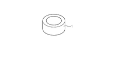
- the perspective view which shows an example of the test piece formed with the sintered sliding material which concerns on this invention.
- the schematic diagram which shows an example of the metal structure of the test piece shown in FIG.
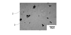
- the structure photograph obtained using the optical microscope which shows an example of the metal structure of the test piece shown in FIG.
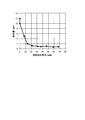
- the graph which shows the relationship between the oxidation increase obtained in the test result of the Example, and the effective porosity.
- the graph which shows the relationship between the abrasion loss obtained in the test result of the Example, and the hard phase ratio.
- FIG. 1 shows a cylindrical bearing member 1 made of a heat-resistant sintered material according to the present invention.
- This bearing member 1 is used for a bearing incorporated in a nozzle mechanism or a valve mechanism for a turbocharger as an example.
- the first heat-resistant sintered material constituting the bearing member 1 contains Cr: 25 to 50%, Ni: 2 to 25%, P: 0.2 to 1.2% by mass, and the balance It consists of a sintered material having a composition comprising Fe and inevitable impurities and having a structure comprising a Fe—Cr matrix phase and a hard phase consisting of Cr—Fe alloy grains dispersed inside the matrix phase.
- the second heat-resistant sintered material constituting the bearing member 1 is made of Cr: 25-50%, Mo: 0.5-3%, P: 0.2-1.2% instead of the above composition. And a sintered material having a composition comprising the remaining Fe and inevitable impurities and having a structure comprising a Fe—Cr matrix and a hard phase comprising Cr—Fe alloy grains dispersed inside the matrix. .
- the first heat-resistant sintered material includes Fe—Cr—Ni alloy powder, Cr—Fe alloy powder, Ni—P alloy powder or Fe— It is obtained by weighing the P alloy powder so as to have the above composition range, press-molding the mixed powder obtained by uniform mixing, and sintering the obtained press-molded body at 1100 to 1300 ° C.
- Fe—Cr—Mo alloy powder, Cr—Fe alloy powder, and Fe—P alloy powder instead of each alloy powder for obtaining the first heat-resistant sintered material, Fe—Cr—Mo alloy powder, Cr—Fe alloy powder, and Fe—P alloy powder should be used. Is obtained.
- the Fe—Cr matrix containing Cr in the Fe base ensures oxidation resistance and salt damage resistance
- Cr—Fe alloy powder Excellent wear resistance is obtained by the presence of the hard particles.
- the ring-shaped bearing member 1 is configured using a heat-resistant sintered material.
- the heat-resistant sintered material of the present embodiment is a shaft member or rod member provided in a nozzle mechanism or a valve mechanism of a turbocharger. Of course, it can be widely applied to bearing members, plates and the like.
- the total Cr amount means “Cr content (mass%) in the total amount of heat-resistant sintered material”
- the total Ni amount means “Ni content (% by mass) in the total amount of heat-resistant sintered material
- the total Mo amount means “Mo content (mass%) in the total heat-resistant sintered material”
- the total P amount means “P content (mass%) in the total heat-resistant sintered material”.
- the total Cr content is included in both the Fe-based parent phase and the Cr—Fe alloy hard phase, and is preferably included in the range of 25% by mass or more and 50% by mass or less as the entire heat-resistant sintered material. . If the total Cr amount is less than 25% by mass, the salt damage resistance is lowered, and if it is more than 50% by mass, the effective porosity is increased and the oxidation resistance is lowered. When the total Cr content is less than 20% by mass, oxidation resistance is lowered in addition to salt damage resistance. Cr is required to be contained at least 13% by mass in the parent phase for the purpose of improving oxidation resistance.
- 24% by mass in the parent phase is required. It is desirable to include the above. If the amount of Cr in the matrix phase is less than 24% by mass, the salt resistance is inferior. If the amount of Cr is less than 13% by mass, the oxidation resistance is lowered in addition to the salt resistance.
- the amount of Cr in the parent phase is more preferably 24 to 41% by mass.
- the difference in Cr content in the hard phase and Cr content in the matrix phase is preferably 5% by mass or more. More desirably, the difference between the Cr amount in the hard phase and the Cr amount in the matrix phase is 10 to 20% by mass.
- the amount of Cr in the hard phase is preferably in the range of 30 to 61% by mass.
- the amount of Cr in the hard phase is more desirably in the range of 34 to 61% by mass.
- Total Ni content: 2-25% by mass Ni contributes to the improvement of salt damage resistance. If the total amount of Ni is less than 2% by mass, the effect is weak in terms of salt resistance, and even if the total amount of Ni exceeds 25% by mass, the effect is small.
- the total Ni content is more preferably 2 to 8% by mass when the parent phase is a ferrite phase, and 8 to 25% by mass when the austenite phase is used.
- Total Mo content 0.5-3 mass%
- the upper limit of the Mo content is preferably set to 3% by mass.
- the total amount of Mo is more preferably 1.0 to 3.0% by mass.
- Total P amount 0.2-1.2% by mass It is a desirable element for producing a liquid phase during sintering, improving the sinterability of the FeCrNi-based sintered material, reducing the effective porosity as the sintered material, and increasing the density. By containing P, the sinterability is improved and the oxidation resistance is improved. If the P content is less than 0.2% by mass, it is difficult to increase the density, it is difficult to make the effective porosity 2% or less, and the oxidation resistance deteriorates. When the content exceeds 1.2% by mass, salt damage resistance deteriorates.
- the total amount of P is more preferably 0.4 to 0.8% by mass.
- Hard phase In the heat-resistant sintered material of this embodiment, it is preferable that 13 to 67% by volume of a hard phase composed of Cr—Fe alloy grains is dispersed. If the hard phase is 13% by volume or more, the wear resistance is good. On the other hand, when a hard phase exceeds 67 volume% or less, manufacture is difficult. In the heat resistant sintered material, the hard phase is more preferably dispersed in an amount of 15 to 40% by volume.
- the heat-resistant sintered material of the present embodiment includes a hard phase: 13% by volume or more, an Fe—Cr matrix phase: the remainder, and inevitable impurities (a third phase that does not affect the effects of the present invention other than the hard phase and the matrix phase). Including).
- the content of the first component (Fe in the case of Fe-25Cr-20Ni alloy powder) is the remainder, and is omitted.
- Each alloy powder may contain inevitable impurities.
- an alloy powder containing 24-26% by mass of Cr and 18-22% by mass of Ni can be used.
- the content of the Fe—Cr—Ni alloy powder is more preferably 70 to 85% by mass.
- an alloy powder containing 50 to 70% by mass of Cr can be used.
- the content of the Cr—Fe alloy powder is more preferably 13 to 28% by mass.
- Ni—P alloy powder an alloy powder containing 10 to 15% by mass of P can be used.
- the content of the Ni—P alloy powder is more preferably 1 to 10% by mass.
- an alloy powder containing 10 to 30% by mass of P can be used.
- the content of the Fe—P alloy powder is more preferably 1 to 5% by mass.
- the mixed powder is put into a mold of a press apparatus and press-molded to obtain a green compact having a desired shape, for example, a cylindrical shape.
- a desired shape for example, a cylindrical shape.
- hot isostatic pressing (HIP) hot isostatic pressing
- CIP cold isostatic pressing
- various methods may be adopted.
- the green compact is sintered at a predetermined temperature in the range of 1100 to 1300 ° C. for about 0.5 to 2 hours to disperse the hard phase of the high Cr—Fe alloy in the Fe—Cr matrix.
- the cylindrical bearing member 1 shown in FIG. 1 made of the heat-resistant sintered material can be obtained.
- the heat-resistant sintered material constituting the bearing member 1 has a metal structure A in which a Cr—Fe alloy phase 3 as a hard phase is dispersed in an Fe—Cr matrix phase 2 as shown in FIGS. 2 and 3, for example. .
- a Cr—Fe alloy phase 3 as a hard phase is dispersed in an Fe—Cr matrix phase 2 as shown in FIGS. 2 and 3, for example.
- pores 5 generated during sintering may remain.
- the Ni—P alloy powder has a lower melting point than other powders, so that the liquid phase It spreads to the grain boundaries of other powder particles, and has the effect of filling the pores.
- the grain boundaries of the Fe—Cr—Ni alloy powder and the Cr—Fe alloy powder can be filled with the Ni—P alloy in the liquid phase, so that the effective porosity after sintering can be reduced. Therefore, it can be set as a high-density sintered material.
- both the parent phase and the hard phase contain 25% by mass or more of Cr, and thus show good oxidation resistance and salt damage resistance.
- the hard phase is composed of a Cr—Fe phase that is harder than the parent phase, it includes good wear resistance in addition to good oxidation resistance and salt damage resistance.
- the Cr—Fe phase is softer than the high Cr carbide particles used in the conventional material, the wear of the sliding counterpart material can be suppressed more than in the conventional material.
- the above-described bearing member 1 is applied to a bearing portion such as a turbocharger, and is excellent in oxidation resistance, salt resistance, and resistance even when it is slid by a shaft while being exposed to high-temperature exhaust gas. Excellent wear resistance. Further, since the wear of the mating material can be suppressed with respect to the shaft which is the mating material, an effect of suppressing the wear of the shaft can be obtained.
- the heat-resistant sintered material of this embodiment can be used as a constituent material of the shaft of the turbocharger, as well as various mechanical parts provided in an environment exposed to high-temperature corrosive gas with respect to oxidation resistance, salt damage resistance, and wear resistance. Of course, it can be used as a component.
- the heat-resistant sintered material can also be realized in a composition system in which Mo is added instead of Ni.
- a blender of 10-58 mass% Cr-40Fe alloy powder and 1-5 mass% Fe-P alloy powder with respect to 37-89 mass% Fe-25Cr-2Mo alloy powder, etc. To obtain a mixed powder having a desired composition ratio.
- a heat-resistant sintered material can be obtained by sintering this mixed powder into a green compact by a method equivalent to the method for producing the first heat-resistant sintered material.
- Fe—Cr—Mo alloy powder an alloy powder containing 24 to 26% by mass of Cr and 1 to 3% by mass of Mo can be used.
- Cr—Fe alloy powder an alloy powder containing 50 to 70% by mass of Cr can be used.
- Fe—P alloy powder an alloy powder containing 15 to 35 mass% P can be used.
- Example 1 As raw material powders, Fe-25Cr-20Ni alloy powder, Cr-40Fe alloy powder, and Ni-12P alloy powder are prepared, and these raw material alloy powders have final component compositions shown in Tables 1 to 3 below. After blending and mixing for 30 minutes with a V-type mixer, press molding was performed at a molding pressure of 588 MPa to produce a cylindrical green compact. Next, this green compact was sintered in a vacuum atmosphere at a temperature of 1250 to 1280 ° C. for 1.5 hours to obtain a heat-resistant sliding material (Sample Nos. 1 to 29).
- Fe-25Cr-2Mo alloy powder, Cr-40Fe alloy powder, and Fe-27P alloy powder are prepared as raw material powders, and these raw material alloy powders have final component compositions shown in Table 4 below.
- Compound no. Heat resistant sliding materials were obtained in the same manner as in 1 to 29 (Sample Nos. 30 to 35). Each sintered sliding material was formed into a suitable shape for each of the following tests and used for each test.
- “Cr content of parent phase” The amount of Cr in the parent phase (Cr content ratio of the parent phase) in the obtained heat resistant sliding materials 1 to 35 was obtained by measurement using SEM-EDX.
- “Cr amount of hard phase” The Cr amount of the hard phase (Cr content ratio of the hard phase) in the obtained heat-resistant sliding materials 1 to 35 was obtained by measuring using SEM-EDX.
- “Hard phase volume fraction” In the obtained heat resistant sliding materials 1 to 35, the volume fraction of the hard phase was measured by a line segment method. Tissue photographs are taken for each sample, 20 arbitrary straight lines are drawn on the photograph at regular intervals, and the sum of the lengths of these straight lines passing through the hard phase portion is obtained.
- oxidation resistance test In the oxidation resistance test, a ring-shaped heat-resistant baked material having dimensions of outer diameter: 20 mm ⁇ inner diameter: 10 mm ⁇ height: 5 mm and made of FeCrNiMoP-based sintered material having the composition components shown in Tables 1 to 4 below. A binder (bearing member) was obtained and tested. Measured weight change of the above-mentioned ring-shaped heat-resistant sintered material test piece after heating to 800 ° C. in air for 100 hours, and dividing this weight change by the surface area of the sample (weight change per unit surface area) was determined as an increase in oxidation and compared.
- a ring-shaped heat-resistant sintered material having an oxidation increase (weight change per unit surface area) of 7.0 mg / cm 2 or less was evaluated as “A”, and the oxidation increase was 7.0 mg / cm 2 .
- the excess ring-shaped heat-resistant sintered material was evaluated as “B”.
- Abrasion resistance test In order to perform a roll-on block test, a test was performed in which a cylindrical shaft was placed on a block (abrasion test piece) and rotated 90 degrees back and forth. The measurement was performed at a temperature of 600 ° C. for 30 minutes, and the amount of wear was evaluated with 2000 reciprocations. The amount of wear was measured by taking a photograph of the wear surface with a 3D microscope and measuring the wear depth.
- the shape of the abrasion test piece is a rectangular parallelepiped block made of a sintered material having a thickness of 50 ⁇ 10 ⁇ 5 mm.
- the shaft of the mating member is a stainless steel rod made of SUS316 having a diameter of 8 mm and a length of 150 mm.
- the stainless steel rod was pressed against the block at a load of 80 N, and tested by reciprocating as a motor rotation shaft.
- a wear test piece having a wear amount of 4.0 ⁇ m or less was evaluated as “A”, and a wear test piece having a wear amount exceeding 4.0 ⁇ m was evaluated as “B”.
- Salt damage resistance test The salt damage resistance was grasped by a salt spray test (according to JISZ2371). The appearance area ratio of rust on the appearance was evaluated by spraying 5% NaCl aqueous solution with salt water (35 ° C., 24 hours), and a sample having a corrosion area ratio of 1% or less due to the occurrence of rust was accepted.
- the test piece is a ring-shaped test piece having an outer diameter of 20 mm, an inner diameter of 10 mm, and a height of 5 mm.
- A corresponds to a corrosion area ratio of 1% or less due to rust
- B corresponds to a corrosion area ratio due to rust exceeding 1%.
- Table 1 shows the relationship between the total composition and Cr content of the parent phase used for each heat-resistant sintered material sample for each addition amount (wt%) of the hard phase Cr-40Fe alloy powder hard phase.
- the oxidation resistance test result the measurement result of the effective porosity and the determination result thereof, the result of the appearance inspection for the salt damage resistance, the determination result of the wear resistance and the determination result thereof are shown.
- the No. 1 sample in which the addition amount of the hard phase Cr-40Fe alloy powder hard phase is 0% and the total composition is only the parent phase has a high effective porosity and wear. The amount has also increased.
- the sample contains Cr-Fe alloy powder, which is hard particles, added by 10 mass% or more, and contains 26 mass% or more of Cr and 0.6 mass% of P, It has been found that it is excellent in three aspects of oxidation resistance, salt damage resistance and wear resistance. Further, the sample containing 60% by mass of the hard Cr—Fe alloy powder had low powder compressibility and was difficult to impart shape.
- Table 3 (Ni amount) shows that each sample was prepared by fixing the added amount of Cr-40Fe alloy powder, which is hard particles, to 18%, and changing the total amount of Ni by changing the Ni powder to be added.
- the results of an oxidation resistance test, an effective porosity measurement, a salt damage resistance test, and an abrasion resistance test are shown for each sample. From the results of Table 3, it can be seen that when the amount of Ni as the total composition is less than 2.0% by mass, the corrosion area ratio exceeds 1% in the salt damage resistance test. For this reason, it turns out that the amount of Ni of a total composition needs 2.0 mass% or more. Moreover, even if the total amount of Ni was added up to about 20% by mass, no problem occurred.
- Table 2 shows that each sample was prepared by fixing the amount of Cr-40Fe alloy powder, which is hard particles, to 18%, and varying the amount of P in the total composition by adjusting the amount of NiP alloy particles to be added. The results of an oxidation resistance test, an effective porosity measurement, a salt damage resistance test, and an abrasion resistance test for each sample are shown. From Table 2 (P amount), it can be seen that when the P amount as the total composition is less than 0.2% by mass, the oxidation resistance is poor and the effective porosity is high. Further, the No. 23 sample containing 1.4% by mass of P had a corrosion area ratio exceeding 1% in the salt damage resistance test. Therefore, it can be seen that in order to satisfy oxidation resistance, salt damage resistance, and wear resistance, the amount of P in the total composition must be in the range of 0.2 to 1.2 mass%.
- Table 4 shows that each sample was prepared by fixing the amount of Cr-40Fe alloy powder, which is hard particles, to 18%, and varying the amount of Mo in the total composition by adjusting the amount of Mo in the Fe-Cr-Mo alloy particles to be added. The results of an oxidation resistance test, an effective porosity measurement, a salt damage resistance test, and an abrasion resistance test for each sample are shown. From Table 4, when the amount of Mo as a total composition is 0.4% by mass or less (less than 0.5% by mass), there is no effect of improving salt damage resistance, and even if it exceeds 3% by mass, further improvement effect It turns out that there are few.
- FIG. 4 is a graph showing the relationship between the effective porosity of the samples in Table 1 and the increase in oxidation. It can be seen from FIG. 4 that as the effective porosity increases, the amount of oxidation increase increases and it is easy to oxidize. For this reason, it turns out that it is advantageous to make effective porosity small, in order to make oxidation resistance high.
- FIG. 5 is a graph showing the relationship between the hard phase volume ratio and the amount of wear of the samples Nos. 1 to 10 shown in Table 1.
- the amount of wear is large when the ratio (volume%) of the hard phase in the sintered body is 0% and 7.4%, but the amount of wear is greater than 13% by volume. Can be reduced to a sufficiently low range. From this, it can be seen that the ratio of the hard phase of the heat-resistant sintered material is preferably in the range of 13 to 67% by volume.
- the heat-resistant sintered material of the present invention is excellent in oxidation resistance, high-temperature wear resistance, and salt damage resistance. It can be widely applied to shaft members, rod members, bearing members, plates and the like.
Landscapes
- Chemical & Material Sciences (AREA)
- Engineering & Computer Science (AREA)
- Mechanical Engineering (AREA)
- Materials Engineering (AREA)
- Metallurgy (AREA)
- Organic Chemistry (AREA)
- Manufacturing & Machinery (AREA)
- Powder Metallurgy (AREA)
Priority Applications (3)
| Application Number | Priority Date | Filing Date | Title |
|---|---|---|---|
| EP16772619.9A EP3276034B1 (en) | 2015-03-27 | 2016-03-25 | Heat-resistant sintered material having excellent oxidation resistance, wear resistance at high temperatures and salt damage resistance, and method for producing same |
| CN201680017738.6A CN107429350B (zh) | 2015-03-27 | 2016-03-25 | 抗氧化性、高温耐磨损性、耐盐蚀性优异的耐热烧结材及其制造方法 |
| US15/561,375 US10683568B2 (en) | 2015-03-27 | 2016-03-25 | Heat-resistant sintered material having excellent oxidation resistance, high-temperature wear resistance and salt damage resistance, and method for producing same |
Applications Claiming Priority (2)
| Application Number | Priority Date | Filing Date | Title |
|---|---|---|---|
| JP2015-066748 | 2015-03-27 | ||
| JP2015066748A JP6489684B2 (ja) | 2015-03-27 | 2015-03-27 | 耐酸化性、高温耐摩耗性、耐塩害性に優れる耐熱焼結材およびその製造方法 |
Publications (1)
| Publication Number | Publication Date |
|---|---|
| WO2016158738A1 true WO2016158738A1 (ja) | 2016-10-06 |
Family
ID=57005047
Family Applications (1)
| Application Number | Title | Priority Date | Filing Date |
|---|---|---|---|
| PCT/JP2016/059601 Ceased WO2016158738A1 (ja) | 2015-03-27 | 2016-03-25 | 耐酸化性、高温耐摩耗性、耐塩害性に優れる耐熱焼結材およびその製造方法 |
Country Status (5)
| Country | Link |
|---|---|
| US (1) | US10683568B2 (enExample) |
| EP (1) | EP3276034B1 (enExample) |
| JP (1) | JP6489684B2 (enExample) |
| CN (1) | CN107429350B (enExample) |
| WO (1) | WO2016158738A1 (enExample) |
Families Citing this family (2)
| Publication number | Priority date | Publication date | Assignee | Title |
|---|---|---|---|---|
| JP6920877B2 (ja) * | 2017-04-27 | 2021-08-18 | 株式会社ダイヤメット | 高温耐摩耗性、耐塩害性に優れる耐熱焼結材及びその製造方法 |
| JP7546377B2 (ja) * | 2019-04-24 | 2024-09-06 | 株式会社ダイヤメット | 焼結摺動部材およびその製造方法 |
Citations (4)
| Publication number | Priority date | Publication date | Assignee | Title |
|---|---|---|---|---|
| JPH0577025A (ja) * | 1991-05-13 | 1993-03-30 | Riken Corp | 複合カムリング材の製造方法 |
| JP2001303233A (ja) * | 2000-04-26 | 2001-10-31 | Toyo Kohan Co Ltd | 溶融金属に対する耐食性に優れた溶融金属用部材およびその製造方法 |
| WO2005012585A1 (ja) * | 2003-07-31 | 2005-02-10 | Komatsu Ltd. | 焼結摺動部材および作業機連結装置 |
| JP2014169468A (ja) * | 2013-03-01 | 2014-09-18 | Hitachi Chemical Co Ltd | 焼結合金およびその製造方法 |
Family Cites Families (10)
| Publication number | Priority date | Publication date | Assignee | Title |
|---|---|---|---|---|
| GB749472A (en) * | 1952-09-25 | 1956-05-23 | Wargons Ab | A method for the production of metal powders and welding electrodes containing such powders |
| US3785801A (en) * | 1968-03-01 | 1974-01-15 | Int Nickel Co | Consolidated composite materials by powder metallurgy |
| IT1052293B (it) * | 1974-11-30 | 1981-06-20 | Krebsoege Gmbh Sintermetall | Procedimento per la produzione di pezzi omogenei sinterizzati di acciaio legati con manganese |
| JPS56156702A (en) * | 1980-05-06 | 1981-12-03 | Fujitsu Shintaa Kk | Metallic powder for sintering |
| JPH0372052A (ja) * | 1989-08-11 | 1991-03-27 | Mazda Motor Corp | 耐摩性焼結合金の製造方法 |
| US20040069094A1 (en) * | 2002-06-28 | 2004-04-15 | Nippon Piston Ring Co., Ltd. | Iron-based sintered alloy material for valve sheet and process for preparing the same |
| JP4208689B2 (ja) * | 2003-09-30 | 2009-01-14 | 日立粉末冶金株式会社 | 高耐食性ステンレス焼結部材の製造方法 |
| JP5100487B2 (ja) * | 2008-04-25 | 2012-12-19 | 日立粉末冶金株式会社 | 焼結機械部品の製造方法 |
| JP5389577B2 (ja) * | 2008-09-24 | 2014-01-15 | Jfeスチール株式会社 | 粉末冶金法による焼結体の製造方法 |
| JP5987284B2 (ja) * | 2011-09-07 | 2016-09-07 | 日立化成株式会社 | 焼結合金およびその製造方法 |
-
2015
- 2015-03-27 JP JP2015066748A patent/JP6489684B2/ja active Active
-
2016
- 2016-03-25 WO PCT/JP2016/059601 patent/WO2016158738A1/ja not_active Ceased
- 2016-03-25 US US15/561,375 patent/US10683568B2/en active Active
- 2016-03-25 EP EP16772619.9A patent/EP3276034B1/en active Active
- 2016-03-25 CN CN201680017738.6A patent/CN107429350B/zh active Active
Patent Citations (4)
| Publication number | Priority date | Publication date | Assignee | Title |
|---|---|---|---|---|
| JPH0577025A (ja) * | 1991-05-13 | 1993-03-30 | Riken Corp | 複合カムリング材の製造方法 |
| JP2001303233A (ja) * | 2000-04-26 | 2001-10-31 | Toyo Kohan Co Ltd | 溶融金属に対する耐食性に優れた溶融金属用部材およびその製造方法 |
| WO2005012585A1 (ja) * | 2003-07-31 | 2005-02-10 | Komatsu Ltd. | 焼結摺動部材および作業機連結装置 |
| JP2014169468A (ja) * | 2013-03-01 | 2014-09-18 | Hitachi Chemical Co Ltd | 焼結合金およびその製造方法 |
Non-Patent Citations (1)
| Title |
|---|
| See also references of EP3276034A4 * |
Also Published As
| Publication number | Publication date |
|---|---|
| EP3276034B1 (en) | 2020-12-02 |
| EP3276034A1 (en) | 2018-01-31 |
| CN107429350A (zh) | 2017-12-01 |
| US10683568B2 (en) | 2020-06-16 |
| JP6489684B2 (ja) | 2019-03-27 |
| US20180080105A1 (en) | 2018-03-22 |
| JP2016186109A (ja) | 2016-10-27 |
| CN107429350B (zh) | 2020-01-14 |
| EP3276034A4 (en) | 2019-01-23 |
Similar Documents
| Publication | Publication Date | Title |
|---|---|---|
| JP6920877B2 (ja) | 高温耐摩耗性、耐塩害性に優れる耐熱焼結材及びその製造方法 | |
| CN102994896B (zh) | 烧结合金及其制备方法 | |
| US9340857B2 (en) | Sintered alloy and production method therefor | |
| JP5100487B2 (ja) | 焼結機械部品の製造方法 | |
| JP7150406B2 (ja) | 耐熱焼結合金材 | |
| EP2511388B1 (en) | Sintered sliding member | |
| WO2016158738A1 (ja) | 耐酸化性、高温耐摩耗性、耐塩害性に優れる耐熱焼結材およびその製造方法 | |
| US10094009B2 (en) | Sintered alloy and production method therefor | |
| WO2018181015A1 (ja) | 耐酸化性、高温耐摩耗性、耐塩害性に優れる耐熱焼結材及びその製造方法 | |
| JP6678038B2 (ja) | 耐酸化性、高温耐摩耗性、耐塩害性に優れる耐熱焼結材およびその製造方法 | |
| JP6735106B2 (ja) | 高温耐摩耗性、高温強度に優れるCoフリー耐熱焼結材およびその製造方法 | |
| JP7546377B2 (ja) | 焼結摺動部材およびその製造方法 | |
| JP6222815B2 (ja) | 焼結部材 | |
| JP2009263710A (ja) | 焼結機械部品の製造方法 | |
| WO2020218479A1 (ja) | 焼結摺動部材およびその製造方法 | |
| WO2013122076A1 (ja) | 焼結部材 | |
| JP2606327B2 (ja) | 耐摩耗性のすぐれた高強度高靭性Cu基焼結合金 | |
| JPH06101429A (ja) | 内燃機関用鉛含浸鉄系焼結合金製バルブシート | |
| JP2015187296A (ja) | 焼結部材 | |
| JPH06101426A (ja) | 内燃機関用鉄系焼結合金製バルブシート |
Legal Events
| Date | Code | Title | Description |
|---|---|---|---|
| 121 | Ep: the epo has been informed by wipo that ep was designated in this application |
Ref document number: 16772619 Country of ref document: EP Kind code of ref document: A1 |
|
| WWE | Wipo information: entry into national phase |
Ref document number: 15561375 Country of ref document: US |
|
| REEP | Request for entry into the european phase |
Ref document number: 2016772619 Country of ref document: EP |
|
| NENP | Non-entry into the national phase |
Ref country code: DE |