WO2016158738A1 - Heat-resistant sintered material having excellent oxidation resistance, wear resistance at high temperatures and salt damage resistance, and method for producing same - Google Patents
Heat-resistant sintered material having excellent oxidation resistance, wear resistance at high temperatures and salt damage resistance, and method for producing same Download PDFInfo
- Publication number
- WO2016158738A1 WO2016158738A1 PCT/JP2016/059601 JP2016059601W WO2016158738A1 WO 2016158738 A1 WO2016158738 A1 WO 2016158738A1 JP 2016059601 W JP2016059601 W JP 2016059601W WO 2016158738 A1 WO2016158738 A1 WO 2016158738A1
- Authority
- WO
- WIPO (PCT)
- Prior art keywords
- mass
- heat
- resistance
- sintered material
- matrix
- Prior art date
Links
Images


Classifications
-
- C—CHEMISTRY; METALLURGY
- C22—METALLURGY; FERROUS OR NON-FERROUS ALLOYS; TREATMENT OF ALLOYS OR NON-FERROUS METALS
- C22C—ALLOYS
- C22C38/00—Ferrous alloys, e.g. steel alloys
- C22C38/18—Ferrous alloys, e.g. steel alloys containing chromium
- C22C38/40—Ferrous alloys, e.g. steel alloys containing chromium with nickel
-
- B—PERFORMING OPERATIONS; TRANSPORTING
- B22—CASTING; POWDER METALLURGY
- B22F—WORKING METALLIC POWDER; MANUFACTURE OF ARTICLES FROM METALLIC POWDER; MAKING METALLIC POWDER; APPARATUS OR DEVICES SPECIALLY ADAPTED FOR METALLIC POWDER
- B22F1/00—Metallic powder; Treatment of metallic powder, e.g. to facilitate working or to improve properties
-
- B—PERFORMING OPERATIONS; TRANSPORTING
- B22—CASTING; POWDER METALLURGY
- B22F—WORKING METALLIC POWDER; MANUFACTURE OF ARTICLES FROM METALLIC POWDER; MAKING METALLIC POWDER; APPARATUS OR DEVICES SPECIALLY ADAPTED FOR METALLIC POWDER
- B22F3/00—Manufacture of workpieces or articles from metallic powder characterised by the manner of compacting or sintering; Apparatus specially adapted therefor ; Presses and furnaces
- B22F3/12—Both compacting and sintering
- B22F3/16—Both compacting and sintering in successive or repeated steps
-
- B—PERFORMING OPERATIONS; TRANSPORTING
- B22—CASTING; POWDER METALLURGY
- B22F—WORKING METALLIC POWDER; MANUFACTURE OF ARTICLES FROM METALLIC POWDER; MAKING METALLIC POWDER; APPARATUS OR DEVICES SPECIALLY ADAPTED FOR METALLIC POWDER
- B22F5/00—Manufacture of workpieces or articles from metallic powder characterised by the special shape of the product
- B22F5/009—Manufacture of workpieces or articles from metallic powder characterised by the special shape of the product of turbine components other than turbine blades
-
- C—CHEMISTRY; METALLURGY
- C22—METALLURGY; FERROUS OR NON-FERROUS ALLOYS; TREATMENT OF ALLOYS OR NON-FERROUS METALS
- C22C—ALLOYS
- C22C1/00—Making non-ferrous alloys
- C22C1/04—Making non-ferrous alloys by powder metallurgy
- C22C1/045—Alloys based on refractory metals
-
- C—CHEMISTRY; METALLURGY
- C22—METALLURGY; FERROUS OR NON-FERROUS ALLOYS; TREATMENT OF ALLOYS OR NON-FERROUS METALS
- C22C—ALLOYS
- C22C27/00—Alloys based on rhenium or a refractory metal not mentioned in groups C22C14/00 or C22C16/00
- C22C27/06—Alloys based on chromium
-
- C—CHEMISTRY; METALLURGY
- C22—METALLURGY; FERROUS OR NON-FERROUS ALLOYS; TREATMENT OF ALLOYS OR NON-FERROUS METALS
- C22C—ALLOYS
- C22C30/00—Alloys containing less than 50% by weight of each constituent
-
- C—CHEMISTRY; METALLURGY
- C22—METALLURGY; FERROUS OR NON-FERROUS ALLOYS; TREATMENT OF ALLOYS OR NON-FERROUS METALS
- C22C—ALLOYS
- C22C33/00—Making ferrous alloys
- C22C33/02—Making ferrous alloys by powder metallurgy
- C22C33/0207—Using a mixture of prealloyed powders or a master alloy
- C22C33/0214—Using a mixture of prealloyed powders or a master alloy comprising P or a phosphorus compound
-
- C—CHEMISTRY; METALLURGY
- C22—METALLURGY; FERROUS OR NON-FERROUS ALLOYS; TREATMENT OF ALLOYS OR NON-FERROUS METALS
- C22C—ALLOYS
- C22C33/00—Making ferrous alloys
- C22C33/02—Making ferrous alloys by powder metallurgy
- C22C33/0257—Making ferrous alloys by powder metallurgy characterised by the range of the alloying elements
- C22C33/0278—Making ferrous alloys by powder metallurgy characterised by the range of the alloying elements with at least one alloying element having a minimum content above 5%
- C22C33/0285—Making ferrous alloys by powder metallurgy characterised by the range of the alloying elements with at least one alloying element having a minimum content above 5% with Cr, Co, or Ni having a minimum content higher than 5%
-
- C—CHEMISTRY; METALLURGY
- C22—METALLURGY; FERROUS OR NON-FERROUS ALLOYS; TREATMENT OF ALLOYS OR NON-FERROUS METALS
- C22C—ALLOYS
- C22C38/00—Ferrous alloys, e.g. steel alloys
-
- C—CHEMISTRY; METALLURGY
- C22—METALLURGY; FERROUS OR NON-FERROUS ALLOYS; TREATMENT OF ALLOYS OR NON-FERROUS METALS
- C22C—ALLOYS
- C22C38/00—Ferrous alloys, e.g. steel alloys
- C22C38/002—Ferrous alloys, e.g. steel alloys containing In, Mg, or other elements not provided for in one single group C22C38/001 - C22C38/60
-
- C—CHEMISTRY; METALLURGY
- C22—METALLURGY; FERROUS OR NON-FERROUS ALLOYS; TREATMENT OF ALLOYS OR NON-FERROUS METALS
- C22C—ALLOYS
- C22C38/00—Ferrous alloys, e.g. steel alloys
- C22C38/18—Ferrous alloys, e.g. steel alloys containing chromium
- C22C38/22—Ferrous alloys, e.g. steel alloys containing chromium with molybdenum or tungsten
-
- C—CHEMISTRY; METALLURGY
- C22—METALLURGY; FERROUS OR NON-FERROUS ALLOYS; TREATMENT OF ALLOYS OR NON-FERROUS METALS
- C22C—ALLOYS
- C22C38/00—Ferrous alloys, e.g. steel alloys
- C22C38/18—Ferrous alloys, e.g. steel alloys containing chromium
- C22C38/40—Ferrous alloys, e.g. steel alloys containing chromium with nickel
- C22C38/44—Ferrous alloys, e.g. steel alloys containing chromium with nickel with molybdenum or tungsten
-
- B—PERFORMING OPERATIONS; TRANSPORTING
- B22—CASTING; POWDER METALLURGY
- B22F—WORKING METALLIC POWDER; MANUFACTURE OF ARTICLES FROM METALLIC POWDER; MAKING METALLIC POWDER; APPARATUS OR DEVICES SPECIALLY ADAPTED FOR METALLIC POWDER
- B22F2301/00—Metallic composition of the powder or its coating
- B22F2301/35—Iron
-
- B—PERFORMING OPERATIONS; TRANSPORTING
- B22—CASTING; POWDER METALLURGY
- B22F—WORKING METALLIC POWDER; MANUFACTURE OF ARTICLES FROM METALLIC POWDER; MAKING METALLIC POWDER; APPARATUS OR DEVICES SPECIALLY ADAPTED FOR METALLIC POWDER
- B22F2998/00—Supplementary information concerning processes or compositions relating to powder metallurgy
- B22F2998/10—Processes characterised by the sequence of their steps
Definitions
- the present invention relates to a heat-resistant sintered material excellent in oxidation resistance, high-temperature wear resistance and salt damage resistance, and a method for producing the same.
- Turbo of the internal combustion engine that uses the energy of exhaust gas to rotate the turbine at high speed, drives the centrifugal compressor using the rotational force, and sends the compressed air into the engine to increase the thermal efficiency of the internal combustion engine
- the charger is known.
- a turbocharger attached to an internal combustion engine is provided with a nozzle mechanism and a valve mechanism for diverting a part of exhaust gas and adjusting the amount of flow into the turbine.
- the mechanical parts such as bearings and bushes incorporated in this turbocharger are always exposed to high-temperature and corrosive exhaust gas discharged from the engine, and are also movable parts and have excellent sliding characteristics. desired.
- heat-resistant parts made of molten or sintered material made of high Cr cast steel have been used.
- the total composition is Cr: 11.75 to 39.98%, Ni: 5.58 to 24.98%, Si: 0.8. 16 to 2.54, P: 0.1 to 1.5%, C: 0.58 to 3.62%, and the balance is Fe and inevitable impurities, and metal carbide having an average particle size of 10 to 50 ⁇ m is precipitated.
- a sintered alloy having a metal structure in which the particle size DB is DA> DB is known (see Patent Document 1).
- Properties desired for this type of conventional heat-resistant parts include oxidation resistance, wear resistance (self-wearing, low opponent attack), salt damage resistance, etc.
- a high-Cr cast steel melt or sintered material that can satisfy these requirements is applied.
- an alloy having a composition of Fe-34Cr-2Mo-2Si-1.2C is known as a molten material for ferritic high Cr cast steel, and Fe-34Cr-2Mo- as a sintered material for ferritic high Cr cast steel.
- a sintered alloy having a composition of 2Si-2C or a sintered alloy having a composition of Fe-30Cr-10Ni-1Mo-1Si-2.5C is applied.
- these alloys In order to improve oxidation resistance, these alloys have a higher Cr composition, whereas ordinary stainless steel contains at most about 25% chromium.
- these alloys employ a structure in which Cr carbides are precipitated as hard particles in the parent phase in order to improve wear resistance. This type of alloy in which Cr carbide is precipitated has a problem that the amount of Cr in the parent phase is reduced due to the effect of Cr carbide generation.
- the amount of Cr in the parent phase can be controlled by controlling the total amount of Cr in the entire alloy, and can be adjusted by controlling the amount of precipitated Cr carbide hard particles by the C content.
- the present inventor has intensively studied the oxidation resistance and high temperature wear resistance of the sintered material. Instead of using the high Cr carbide particles as the hard particles, the high resistance Cr It was found that the heat resistant sintered material was excellent in heat resistance and high temperature wear resistance, could reduce the wear of the counterpart material, and was excellent in salt damage resistance, and reached the present invention.
- the present invention has been made in view of the circumstances as described above, and is excellent in oxidation resistance and high-temperature wear resistance, can reduce wear of the counterpart material, and heat-resistant sintered material excellent in salt damage resistance and its The purpose is to provide a manufacturing method.
- the heat-resistant sintered material of the present invention contains Cr: 25 to 50%, Ni: 2 to 25%, and P: 0.2 to 1.2% by mass% in order to solve the above-mentioned problems. Having a composition consisting of the balance Fe and inevitable impurities, Having a structure comprising a Fe—Cr matrix and a hard phase composed of Cr—Fe alloy grains dispersed therein; The amount of Cr in the Fe—Cr matrix is 24 to 41% by mass, and the amount of Cr in the hard phase is 30 to 61% by mass, The effective porosity is 2% or less.
- the heat-resistant sintered material contains Cr, Ni, and P in a good balance in Fe, and the Fe—Cr matrix contains a desirable amount of a hard phase composed of Cr—Fe alloy grains, so that it has excellent corrosion resistance and heat resistance.
- a heat-resistant sintered material excellent in wear resistance can be obtained.
- the addition of P makes it possible to increase the density of the heat-resistant sintered material, that is, to reduce the effective porosity, and improve the oxidation resistance.
- the heat-resistant sintered material of the present invention contains Cr: 25-50%, Mo: 0.5-3%, P: 0.2-1.2% by mass in order to solve the above-mentioned problems. And having a composition consisting of the balance Fe and inevitable impurities, Having a structure comprising a Fe—Cr matrix and a hard phase composed of Cr—Fe alloy grains dispersed therein; The amount of Cr in the Fe—Cr matrix is 24 to 41% by mass, and the amount of Cr in the hard phase is 30 to 61% by mass, The effective porosity is 2% or less.
- Mo By adding an appropriate amount of Mo to the heat-resistant sintered material, a heat-resistant sintered material having excellent corrosion resistance and heat resistance and excellent wear resistance can be obtained without containing Ni.
- the heat-resistant sintered material described in (1) or (2) may have a configuration in which the hard phase is dispersed in an amount of 13 to 67% by volume.
- the method for producing the heat-resistant sintered material of the present invention is as follows: Fe—Cr—Ni alloy powder, Cr—Fe alloy powder and Ni—P alloy powder in a mass percentage of Cr: 25-50%, Ni: 2-25%, P: 0.2-1.2% Mixing to obtain a mixed powder, Pressing the mixed powder to produce a green compact; Sintering the green compact at 1100-1300 ° C., A structure having a Fe—Cr matrix and a hard phase composed of Cr—Fe alloy grains dispersed therein, wherein the Cr content of the Fe—Cr matrix is 24 to 41% by mass; A heat resistant sintered material having a Cr content of 30 to 61% by mass and an effective porosity of 2% or less is obtained.
- the method for producing the heat-resistant sintered material of the present invention is as follows: Fe—Cr—Mo alloy powder, Cr—Fe alloy powder, and Fe—P alloy powder in terms of mass% are Cr: 25-50%, Mo: 0.5-3%, P: 0.2-1.2%.
- the ratio of the hard phase in the matrix can be in the range of 13 to 67% by volume.
- the present invention relates to a heat resistant sintered material based on the composition of FeCrNiP or FeCrMoP, in which hard particles of a Cr—Fe alloy phase are dispersed in an Fe—Cr matrix phase having high corrosion resistance.
- the heat-resistant sintered material has better oxidation resistance and excellent high-temperature wear resistance by dispersing the Cr-Fe alloy phase, which is softer than the conventional high Cr carbide particles and harder than the parent phase.
- a heat-resistant sintered material excellent in salt damage resistance can be provided.
- the Cr—Fe alloy phase is softer than the high Cr carbide particles of the conventional material, the opponent attack can be made lower than that of the conventional material, and the wear of the sliding counterpart material can be suppressed.
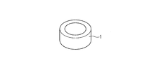
- the perspective view which shows an example of the test piece formed with the sintered sliding material which concerns on this invention.
- the schematic diagram which shows an example of the metal structure of the test piece shown in FIG.
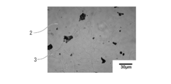
- the structure photograph obtained using the optical microscope which shows an example of the metal structure of the test piece shown in FIG.
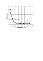
- the graph which shows the relationship between the oxidation increase obtained in the test result of the Example, and the effective porosity.
- the graph which shows the relationship between the abrasion loss obtained in the test result of the Example, and the hard phase ratio.
- FIG. 1 shows a cylindrical bearing member 1 made of a heat-resistant sintered material according to the present invention.
- This bearing member 1 is used for a bearing incorporated in a nozzle mechanism or a valve mechanism for a turbocharger as an example.
- the first heat-resistant sintered material constituting the bearing member 1 contains Cr: 25 to 50%, Ni: 2 to 25%, P: 0.2 to 1.2% by mass, and the balance It consists of a sintered material having a composition comprising Fe and inevitable impurities and having a structure comprising a Fe—Cr matrix phase and a hard phase consisting of Cr—Fe alloy grains dispersed inside the matrix phase.
- the second heat-resistant sintered material constituting the bearing member 1 is made of Cr: 25-50%, Mo: 0.5-3%, P: 0.2-1.2% instead of the above composition. And a sintered material having a composition comprising the remaining Fe and inevitable impurities and having a structure comprising a Fe—Cr matrix and a hard phase comprising Cr—Fe alloy grains dispersed inside the matrix. .
- the first heat-resistant sintered material includes Fe—Cr—Ni alloy powder, Cr—Fe alloy powder, Ni—P alloy powder or Fe— It is obtained by weighing the P alloy powder so as to have the above composition range, press-molding the mixed powder obtained by uniform mixing, and sintering the obtained press-molded body at 1100 to 1300 ° C.
- Fe—Cr—Mo alloy powder, Cr—Fe alloy powder, and Fe—P alloy powder instead of each alloy powder for obtaining the first heat-resistant sintered material, Fe—Cr—Mo alloy powder, Cr—Fe alloy powder, and Fe—P alloy powder should be used. Is obtained.
- the Fe—Cr matrix containing Cr in the Fe base ensures oxidation resistance and salt damage resistance
- Cr—Fe alloy powder Excellent wear resistance is obtained by the presence of the hard particles.
- the ring-shaped bearing member 1 is configured using a heat-resistant sintered material.
- the heat-resistant sintered material of the present embodiment is a shaft member or rod member provided in a nozzle mechanism or a valve mechanism of a turbocharger. Of course, it can be widely applied to bearing members, plates and the like.
- the total Cr amount means “Cr content (mass%) in the total amount of heat-resistant sintered material”
- the total Ni amount means “Ni content (% by mass) in the total amount of heat-resistant sintered material
- the total Mo amount means “Mo content (mass%) in the total heat-resistant sintered material”
- the total P amount means “P content (mass%) in the total heat-resistant sintered material”.
- the total Cr content is included in both the Fe-based parent phase and the Cr—Fe alloy hard phase, and is preferably included in the range of 25% by mass or more and 50% by mass or less as the entire heat-resistant sintered material. . If the total Cr amount is less than 25% by mass, the salt damage resistance is lowered, and if it is more than 50% by mass, the effective porosity is increased and the oxidation resistance is lowered. When the total Cr content is less than 20% by mass, oxidation resistance is lowered in addition to salt damage resistance. Cr is required to be contained at least 13% by mass in the parent phase for the purpose of improving oxidation resistance.
- 24% by mass in the parent phase is required. It is desirable to include the above. If the amount of Cr in the matrix phase is less than 24% by mass, the salt resistance is inferior. If the amount of Cr is less than 13% by mass, the oxidation resistance is lowered in addition to the salt resistance.
- the amount of Cr in the parent phase is more preferably 24 to 41% by mass.
- the difference in Cr content in the hard phase and Cr content in the matrix phase is preferably 5% by mass or more. More desirably, the difference between the Cr amount in the hard phase and the Cr amount in the matrix phase is 10 to 20% by mass.
- the amount of Cr in the hard phase is preferably in the range of 30 to 61% by mass.
- the amount of Cr in the hard phase is more desirably in the range of 34 to 61% by mass.
- Total Ni content: 2-25% by mass Ni contributes to the improvement of salt damage resistance. If the total amount of Ni is less than 2% by mass, the effect is weak in terms of salt resistance, and even if the total amount of Ni exceeds 25% by mass, the effect is small.
- the total Ni content is more preferably 2 to 8% by mass when the parent phase is a ferrite phase, and 8 to 25% by mass when the austenite phase is used.
- Total Mo content 0.5-3 mass%
- the upper limit of the Mo content is preferably set to 3% by mass.
- the total amount of Mo is more preferably 1.0 to 3.0% by mass.
- Total P amount 0.2-1.2% by mass It is a desirable element for producing a liquid phase during sintering, improving the sinterability of the FeCrNi-based sintered material, reducing the effective porosity as the sintered material, and increasing the density. By containing P, the sinterability is improved and the oxidation resistance is improved. If the P content is less than 0.2% by mass, it is difficult to increase the density, it is difficult to make the effective porosity 2% or less, and the oxidation resistance deteriorates. When the content exceeds 1.2% by mass, salt damage resistance deteriorates.
- the total amount of P is more preferably 0.4 to 0.8% by mass.
- Hard phase In the heat-resistant sintered material of this embodiment, it is preferable that 13 to 67% by volume of a hard phase composed of Cr—Fe alloy grains is dispersed. If the hard phase is 13% by volume or more, the wear resistance is good. On the other hand, when a hard phase exceeds 67 volume% or less, manufacture is difficult. In the heat resistant sintered material, the hard phase is more preferably dispersed in an amount of 15 to 40% by volume.
- the heat-resistant sintered material of the present embodiment includes a hard phase: 13% by volume or more, an Fe—Cr matrix phase: the remainder, and inevitable impurities (a third phase that does not affect the effects of the present invention other than the hard phase and the matrix phase). Including).
- the content of the first component (Fe in the case of Fe-25Cr-20Ni alloy powder) is the remainder, and is omitted.
- Each alloy powder may contain inevitable impurities.
- an alloy powder containing 24-26% by mass of Cr and 18-22% by mass of Ni can be used.
- the content of the Fe—Cr—Ni alloy powder is more preferably 70 to 85% by mass.
- an alloy powder containing 50 to 70% by mass of Cr can be used.
- the content of the Cr—Fe alloy powder is more preferably 13 to 28% by mass.
- Ni—P alloy powder an alloy powder containing 10 to 15% by mass of P can be used.
- the content of the Ni—P alloy powder is more preferably 1 to 10% by mass.
- an alloy powder containing 10 to 30% by mass of P can be used.
- the content of the Fe—P alloy powder is more preferably 1 to 5% by mass.
- the mixed powder is put into a mold of a press apparatus and press-molded to obtain a green compact having a desired shape, for example, a cylindrical shape.
- a desired shape for example, a cylindrical shape.
- hot isostatic pressing (HIP) hot isostatic pressing
- CIP cold isostatic pressing
- various methods may be adopted.
- the green compact is sintered at a predetermined temperature in the range of 1100 to 1300 ° C. for about 0.5 to 2 hours to disperse the hard phase of the high Cr—Fe alloy in the Fe—Cr matrix.
- the cylindrical bearing member 1 shown in FIG. 1 made of the heat-resistant sintered material can be obtained.
- the heat-resistant sintered material constituting the bearing member 1 has a metal structure A in which a Cr—Fe alloy phase 3 as a hard phase is dispersed in an Fe—Cr matrix phase 2 as shown in FIGS. 2 and 3, for example. .
- a Cr—Fe alloy phase 3 as a hard phase is dispersed in an Fe—Cr matrix phase 2 as shown in FIGS. 2 and 3, for example.
- pores 5 generated during sintering may remain.
- the Ni—P alloy powder has a lower melting point than other powders, so that the liquid phase It spreads to the grain boundaries of other powder particles, and has the effect of filling the pores.
- the grain boundaries of the Fe—Cr—Ni alloy powder and the Cr—Fe alloy powder can be filled with the Ni—P alloy in the liquid phase, so that the effective porosity after sintering can be reduced. Therefore, it can be set as a high-density sintered material.
- both the parent phase and the hard phase contain 25% by mass or more of Cr, and thus show good oxidation resistance and salt damage resistance.
- the hard phase is composed of a Cr—Fe phase that is harder than the parent phase, it includes good wear resistance in addition to good oxidation resistance and salt damage resistance.
- the Cr—Fe phase is softer than the high Cr carbide particles used in the conventional material, the wear of the sliding counterpart material can be suppressed more than in the conventional material.
- the above-described bearing member 1 is applied to a bearing portion such as a turbocharger, and is excellent in oxidation resistance, salt resistance, and resistance even when it is slid by a shaft while being exposed to high-temperature exhaust gas. Excellent wear resistance. Further, since the wear of the mating material can be suppressed with respect to the shaft which is the mating material, an effect of suppressing the wear of the shaft can be obtained.
- the heat-resistant sintered material of this embodiment can be used as a constituent material of the shaft of the turbocharger, as well as various mechanical parts provided in an environment exposed to high-temperature corrosive gas with respect to oxidation resistance, salt damage resistance, and wear resistance. Of course, it can be used as a component.
- the heat-resistant sintered material can also be realized in a composition system in which Mo is added instead of Ni.
- a blender of 10-58 mass% Cr-40Fe alloy powder and 1-5 mass% Fe-P alloy powder with respect to 37-89 mass% Fe-25Cr-2Mo alloy powder, etc. To obtain a mixed powder having a desired composition ratio.
- a heat-resistant sintered material can be obtained by sintering this mixed powder into a green compact by a method equivalent to the method for producing the first heat-resistant sintered material.
- Fe—Cr—Mo alloy powder an alloy powder containing 24 to 26% by mass of Cr and 1 to 3% by mass of Mo can be used.
- Cr—Fe alloy powder an alloy powder containing 50 to 70% by mass of Cr can be used.
- Fe—P alloy powder an alloy powder containing 15 to 35 mass% P can be used.
- Example 1 As raw material powders, Fe-25Cr-20Ni alloy powder, Cr-40Fe alloy powder, and Ni-12P alloy powder are prepared, and these raw material alloy powders have final component compositions shown in Tables 1 to 3 below. After blending and mixing for 30 minutes with a V-type mixer, press molding was performed at a molding pressure of 588 MPa to produce a cylindrical green compact. Next, this green compact was sintered in a vacuum atmosphere at a temperature of 1250 to 1280 ° C. for 1.5 hours to obtain a heat-resistant sliding material (Sample Nos. 1 to 29).
- Fe-25Cr-2Mo alloy powder, Cr-40Fe alloy powder, and Fe-27P alloy powder are prepared as raw material powders, and these raw material alloy powders have final component compositions shown in Table 4 below.
- Compound no. Heat resistant sliding materials were obtained in the same manner as in 1 to 29 (Sample Nos. 30 to 35). Each sintered sliding material was formed into a suitable shape for each of the following tests and used for each test.
- “Cr content of parent phase” The amount of Cr in the parent phase (Cr content ratio of the parent phase) in the obtained heat resistant sliding materials 1 to 35 was obtained by measurement using SEM-EDX.
- “Cr amount of hard phase” The Cr amount of the hard phase (Cr content ratio of the hard phase) in the obtained heat-resistant sliding materials 1 to 35 was obtained by measuring using SEM-EDX.
- “Hard phase volume fraction” In the obtained heat resistant sliding materials 1 to 35, the volume fraction of the hard phase was measured by a line segment method. Tissue photographs are taken for each sample, 20 arbitrary straight lines are drawn on the photograph at regular intervals, and the sum of the lengths of these straight lines passing through the hard phase portion is obtained.
- oxidation resistance test In the oxidation resistance test, a ring-shaped heat-resistant baked material having dimensions of outer diameter: 20 mm ⁇ inner diameter: 10 mm ⁇ height: 5 mm and made of FeCrNiMoP-based sintered material having the composition components shown in Tables 1 to 4 below. A binder (bearing member) was obtained and tested. Measured weight change of the above-mentioned ring-shaped heat-resistant sintered material test piece after heating to 800 ° C. in air for 100 hours, and dividing this weight change by the surface area of the sample (weight change per unit surface area) was determined as an increase in oxidation and compared.
- a ring-shaped heat-resistant sintered material having an oxidation increase (weight change per unit surface area) of 7.0 mg / cm 2 or less was evaluated as “A”, and the oxidation increase was 7.0 mg / cm 2 .
- the excess ring-shaped heat-resistant sintered material was evaluated as “B”.
- Abrasion resistance test In order to perform a roll-on block test, a test was performed in which a cylindrical shaft was placed on a block (abrasion test piece) and rotated 90 degrees back and forth. The measurement was performed at a temperature of 600 ° C. for 30 minutes, and the amount of wear was evaluated with 2000 reciprocations. The amount of wear was measured by taking a photograph of the wear surface with a 3D microscope and measuring the wear depth.
- the shape of the abrasion test piece is a rectangular parallelepiped block made of a sintered material having a thickness of 50 ⁇ 10 ⁇ 5 mm.
- the shaft of the mating member is a stainless steel rod made of SUS316 having a diameter of 8 mm and a length of 150 mm.
- the stainless steel rod was pressed against the block at a load of 80 N, and tested by reciprocating as a motor rotation shaft.
- a wear test piece having a wear amount of 4.0 ⁇ m or less was evaluated as “A”, and a wear test piece having a wear amount exceeding 4.0 ⁇ m was evaluated as “B”.
- Salt damage resistance test The salt damage resistance was grasped by a salt spray test (according to JISZ2371). The appearance area ratio of rust on the appearance was evaluated by spraying 5% NaCl aqueous solution with salt water (35 ° C., 24 hours), and a sample having a corrosion area ratio of 1% or less due to the occurrence of rust was accepted.
- the test piece is a ring-shaped test piece having an outer diameter of 20 mm, an inner diameter of 10 mm, and a height of 5 mm.
- A corresponds to a corrosion area ratio of 1% or less due to rust
- B corresponds to a corrosion area ratio due to rust exceeding 1%.
- Table 1 shows the relationship between the total composition and Cr content of the parent phase used for each heat-resistant sintered material sample for each addition amount (wt%) of the hard phase Cr-40Fe alloy powder hard phase.
- the oxidation resistance test result the measurement result of the effective porosity and the determination result thereof, the result of the appearance inspection for the salt damage resistance, the determination result of the wear resistance and the determination result thereof are shown.
- the No. 1 sample in which the addition amount of the hard phase Cr-40Fe alloy powder hard phase is 0% and the total composition is only the parent phase has a high effective porosity and wear. The amount has also increased.
- the sample contains Cr-Fe alloy powder, which is hard particles, added by 10 mass% or more, and contains 26 mass% or more of Cr and 0.6 mass% of P, It has been found that it is excellent in three aspects of oxidation resistance, salt damage resistance and wear resistance. Further, the sample containing 60% by mass of the hard Cr—Fe alloy powder had low powder compressibility and was difficult to impart shape.
- Table 3 (Ni amount) shows that each sample was prepared by fixing the added amount of Cr-40Fe alloy powder, which is hard particles, to 18%, and changing the total amount of Ni by changing the Ni powder to be added.
- the results of an oxidation resistance test, an effective porosity measurement, a salt damage resistance test, and an abrasion resistance test are shown for each sample. From the results of Table 3, it can be seen that when the amount of Ni as the total composition is less than 2.0% by mass, the corrosion area ratio exceeds 1% in the salt damage resistance test. For this reason, it turns out that the amount of Ni of a total composition needs 2.0 mass% or more. Moreover, even if the total amount of Ni was added up to about 20% by mass, no problem occurred.
- Table 2 shows that each sample was prepared by fixing the amount of Cr-40Fe alloy powder, which is hard particles, to 18%, and varying the amount of P in the total composition by adjusting the amount of NiP alloy particles to be added. The results of an oxidation resistance test, an effective porosity measurement, a salt damage resistance test, and an abrasion resistance test for each sample are shown. From Table 2 (P amount), it can be seen that when the P amount as the total composition is less than 0.2% by mass, the oxidation resistance is poor and the effective porosity is high. Further, the No. 23 sample containing 1.4% by mass of P had a corrosion area ratio exceeding 1% in the salt damage resistance test. Therefore, it can be seen that in order to satisfy oxidation resistance, salt damage resistance, and wear resistance, the amount of P in the total composition must be in the range of 0.2 to 1.2 mass%.
- Table 4 shows that each sample was prepared by fixing the amount of Cr-40Fe alloy powder, which is hard particles, to 18%, and varying the amount of Mo in the total composition by adjusting the amount of Mo in the Fe-Cr-Mo alloy particles to be added. The results of an oxidation resistance test, an effective porosity measurement, a salt damage resistance test, and an abrasion resistance test for each sample are shown. From Table 4, when the amount of Mo as a total composition is 0.4% by mass or less (less than 0.5% by mass), there is no effect of improving salt damage resistance, and even if it exceeds 3% by mass, further improvement effect It turns out that there are few.
- FIG. 4 is a graph showing the relationship between the effective porosity of the samples in Table 1 and the increase in oxidation. It can be seen from FIG. 4 that as the effective porosity increases, the amount of oxidation increase increases and it is easy to oxidize. For this reason, it turns out that it is advantageous to make effective porosity small, in order to make oxidation resistance high.
- FIG. 5 is a graph showing the relationship between the hard phase volume ratio and the amount of wear of the samples Nos. 1 to 10 shown in Table 1.
- the amount of wear is large when the ratio (volume%) of the hard phase in the sintered body is 0% and 7.4%, but the amount of wear is greater than 13% by volume. Can be reduced to a sufficiently low range. From this, it can be seen that the ratio of the hard phase of the heat-resistant sintered material is preferably in the range of 13 to 67% by volume.
- the heat-resistant sintered material of the present invention is excellent in oxidation resistance, high-temperature wear resistance, and salt damage resistance. It can be widely applied to shaft members, rod members, bearing members, plates and the like.
Abstract
The purpose of this heat-resistant sintered material and a production method thereof is to obtain a heat-resistant sintered material that has excellent oxidation resistance, wear resistance at high temperatures, and salt damage resistance. This heat-resistant sintered material is characterized by: having a composition that contains, in mass%, 25-50% of Cr, 2-25% of Ni and 0.2-1.2% of P, with the balance made up of Fe and unavoidable impurities; and having a structure that comprises an Fe-Cr matrix and hard phases that are dispersed within the Fe-Cr matrix and are composed of Cr-Fe alloy grains. This heat-resistant sintered material is also characterized in that: the Cr content in the Fe-Cr matrix is 24-41% by mass; the Cr content in the hard phases is 30-61% by mass; and the intercommunicating porosity is 2% or less.
Description
本発明は、耐酸化性、高温耐摩耗性、耐塩害性に優れる耐熱焼結材及びその製造方法に関する。
本願は、2015年3月27日に、日本に出願された特願2015-066748号に基づき優先権を主張し、その内容をここに援用する。 The present invention relates to a heat-resistant sintered material excellent in oxidation resistance, high-temperature wear resistance and salt damage resistance, and a method for producing the same.
This application claims priority on March 27, 2015 based on Japanese Patent Application No. 2015-0667748 filed in Japan, the contents of which are incorporated herein by reference.
内燃機関において排ガスのエネルギーを利用してタービンを高速回転させ、その回転力を利用して遠心式圧縮機を駆動し、圧縮した空気をエンジン内に送り込み、内燃機関としての熱効率を高める方式のターボチャージャーが知られている。
内燃機関に付設されるターボチャージャーにおいては、排ガスの一部を分流してタービンへの流入量を調節するノズル機構やバルブ機構が設けられている。
このターボチャージャーに組み込まれる軸受けやブッシュなどの機構部品は、エンジンから排出される高温かつ腐食性の排ガスに常に晒される上に、可動部品であり、摺動特性の面においても優れていることが望まれる。 Turbo of the internal combustion engine that uses the energy of exhaust gas to rotate the turbine at high speed, drives the centrifugal compressor using the rotational force, and sends the compressed air into the engine to increase the thermal efficiency of the internal combustion engine The charger is known.
A turbocharger attached to an internal combustion engine is provided with a nozzle mechanism and a valve mechanism for diverting a part of exhaust gas and adjusting the amount of flow into the turbine.
The mechanical parts such as bearings and bushes incorporated in this turbocharger are always exposed to high-temperature and corrosive exhaust gas discharged from the engine, and are also movable parts and have excellent sliding characteristics. desired.
この種の高温かつ腐食性の排ガスに晒される摺動部品においては、従来、高Cr鋳鋼からなる溶製材あるいは焼結材の耐熱部品が使用されている。
従来知られている耐熱部品用途の焼結合金の一例として、全体組成が、質量%で、Cr:11.75~39.98%、Ni:5.58~24.98%、Si:0.16~2.54、P:0.1~1.5%、C:0.58~3.62%、および残部がFeおよび不可避不純物からなり、平均粒子径が10~50μmの金属炭化物が析出する相Aと、平均粒子径が10μm以下の金属炭化物が析出する相Bが斑状に分布するとともに、前記相Aに析出する金属炭化物の平均粒子径DAと前記相Bに析出する金属炭化物の平均粒子径DBが、DA>DBとなる金属組織を示す焼結合金が知られている(特許文献1参照)。 In sliding parts exposed to this kind of high-temperature and corrosive exhaust gas, conventionally, heat-resistant parts made of molten or sintered material made of high Cr cast steel have been used.
As an example of a conventionally known sintered alloy for heat-resistant parts, the total composition is Cr: 11.75 to 39.98%, Ni: 5.58 to 24.98%, Si: 0.8. 16 to 2.54, P: 0.1 to 1.5%, C: 0.58 to 3.62%, and the balance is Fe and inevitable impurities, and metal carbide having an average particle size of 10 to 50 μm is precipitated. Phase A and phase B in which metal carbide having an average particle diameter of 10 μm or less is distributed in a patchy manner, and the average particle diameter DA of metal carbide deposited in phase A and the average of metal carbide deposited in phase B A sintered alloy having a metal structure in which the particle size DB is DA> DB is known (see Patent Document 1).
特許文献1に記載されている焼結合金を含め、この種従来の耐熱部品に望まれる特性として、耐酸化性、耐摩耗性(自己摩耗、低相手攻撃性)、耐塩害性などがあり、これらの要望を満たし得る高Cr鋳鋼の溶製材あるいは焼結材が適用されている。
例えば、フェライト系の高Cr鋳鋼の溶製材として、Fe-34Cr-2Mo-2Si-1.2Cなる組成の合金が知られ、フェライト系の高Cr鋳鋼の焼結材として、Fe-34Cr-2Mo-2Si-2Cなる組成の焼結合金あるいはFe-30Cr-10Ni-1Mo-1Si-2.5Cなる組成の焼結合金が適用されている。 Properties desired for this type of conventional heat-resistant parts, including the sintered alloy described inPatent Document 1, include oxidation resistance, wear resistance (self-wearing, low opponent attack), salt damage resistance, etc. A high-Cr cast steel melt or sintered material that can satisfy these requirements is applied.
For example, an alloy having a composition of Fe-34Cr-2Mo-2Si-1.2C is known as a molten material for ferritic high Cr cast steel, and Fe-34Cr-2Mo- as a sintered material for ferritic high Cr cast steel. A sintered alloy having a composition of 2Si-2C or a sintered alloy having a composition of Fe-30Cr-10Ni-1Mo-1Si-2.5C is applied.
例えば、フェライト系の高Cr鋳鋼の溶製材として、Fe-34Cr-2Mo-2Si-1.2Cなる組成の合金が知られ、フェライト系の高Cr鋳鋼の焼結材として、Fe-34Cr-2Mo-2Si-2Cなる組成の焼結合金あるいはFe-30Cr-10Ni-1Mo-1Si-2.5Cなる組成の焼結合金が適用されている。 Properties desired for this type of conventional heat-resistant parts, including the sintered alloy described in
For example, an alloy having a composition of Fe-34Cr-2Mo-2Si-1.2C is known as a molten material for ferritic high Cr cast steel, and Fe-34Cr-2Mo- as a sintered material for ferritic high Cr cast steel. A sintered alloy having a composition of 2Si-2C or a sintered alloy having a composition of Fe-30Cr-10Ni-1Mo-1Si-2.5C is applied.
これら組成の合金は、耐酸化性向上のため、通常のステンレス鋼が高くとも25%程度のクロムを含有するのに対し、更に高いCr組成とされている。また、これらの合金は、いずれも耐摩耗性向上のためCr炭化物を硬質粒子として母相内に析出させた構造を採用している。
このCr炭化物を析出させるタイプの合金では母相のCr量がCr炭化物生成の影響で低減する問題がある。母相中のCr量は、合金全体のトータルとしてのCr量を制御することで制御できるとともに、Cr炭化物硬質粒子の析出量をC含有量で制御することにより調整することができる。 In order to improve oxidation resistance, these alloys have a higher Cr composition, whereas ordinary stainless steel contains at most about 25% chromium. In addition, these alloys employ a structure in which Cr carbides are precipitated as hard particles in the parent phase in order to improve wear resistance.
This type of alloy in which Cr carbide is precipitated has a problem that the amount of Cr in the parent phase is reduced due to the effect of Cr carbide generation. The amount of Cr in the parent phase can be controlled by controlling the total amount of Cr in the entire alloy, and can be adjusted by controlling the amount of precipitated Cr carbide hard particles by the C content.
ところが、高Cr炭化物粒子の析出を優先させると母相中のCr量が低下するので、耐酸化性、耐塩害性に問題を生じ、高Cr炭化物粒子の数を減らすと耐摩耗性が悪化する問題がある。
これに加え焼結材においては、合金全体のCr量を高くすると粉末の圧縮性が悪化し、目的の形状に成形できない問題がある。
また、高Cr炭化物粒子を母相中に析出させた構造では高Cr炭化物粒子の析出量を増加すると焼結材自身の耐摩耗性は良好となるが、摺動する相手材の損耗が増加する問題がある。 However, if priority is given to precipitation of high Cr carbide particles, the amount of Cr in the matrix phase will decrease, causing problems in oxidation resistance and salt damage resistance. If the number of high Cr carbide particles is reduced, wear resistance will deteriorate. There's a problem.
In addition to this, in the sintered material, if the Cr content of the entire alloy is increased, the compressibility of the powder deteriorates, and there is a problem that it cannot be formed into a desired shape.
In addition, in the structure in which high Cr carbide particles are precipitated in the matrix, increasing the amount of high Cr carbide particles deposited improves the wear resistance of the sintered material itself, but increases the wear of the sliding counterpart. There's a problem.
以上の背景において、本発明者が焼結材における耐酸化性、高温耐摩耗性について鋭意研究したところ、硬質粒子として高Cr炭化物粒子を用いるのではなく、高CrFe合金を採用することで、耐酸化性と高温耐摩耗性に優れ、相手材の摩耗を減少でき、耐塩害性においても優れた耐熱焼結材を提供できることを知見し、本発明に到達した。
In the above background, the present inventor has intensively studied the oxidation resistance and high temperature wear resistance of the sintered material. Instead of using the high Cr carbide particles as the hard particles, the high resistance Cr It was found that the heat resistant sintered material was excellent in heat resistance and high temperature wear resistance, could reduce the wear of the counterpart material, and was excellent in salt damage resistance, and reached the present invention.
本発明は、以上のような事情に鑑みてなされたものであり、耐酸化性と高温耐摩耗性に優れ、相手材の摩耗を減少でき、耐塩害性においても優れた耐熱焼結材及びその製造方法の提供を目的とする。
The present invention has been made in view of the circumstances as described above, and is excellent in oxidation resistance and high-temperature wear resistance, can reduce wear of the counterpart material, and heat-resistant sintered material excellent in salt damage resistance and its The purpose is to provide a manufacturing method.
(1)本発明の耐熱焼結材は前記課題を解決するために、質量%でCr:25~50%、Ni:2~25%、P:0.2~1.2%を含有し、残部Feおよび不可避不純物からなる組成を有し、
Fe-Cr母相とその内部に分散されたCr-Fe合金粒からなる硬質相とを備えた組織を有し、
前記Fe-Cr母相のCr量が質量%で24~41%、前記硬質相中のCr量が質量%で30~61%であること、
有効多孔率が2%以下であることを特徴とする。
耐熱焼結材がCrとNiとPをFe中にバランス良く含有し、Fe-Cr母相中にCr-Fe合金粒からなる硬質相を望ましい量含んでいるので、耐食性と耐熱性に優れ、耐摩耗性にも優れた耐熱焼結材を得ることができる。
P添加により、耐熱焼結材の高密度化すなわち有効多孔率を低減させることが可能となり、耐酸化性が向上する。 (1) The heat-resistant sintered material of the present invention contains Cr: 25 to 50%, Ni: 2 to 25%, and P: 0.2 to 1.2% by mass% in order to solve the above-mentioned problems. Having a composition consisting of the balance Fe and inevitable impurities,
Having a structure comprising a Fe—Cr matrix and a hard phase composed of Cr—Fe alloy grains dispersed therein;
The amount of Cr in the Fe—Cr matrix is 24 to 41% by mass, and the amount of Cr in the hard phase is 30 to 61% by mass,
The effective porosity is 2% or less.
The heat-resistant sintered material contains Cr, Ni, and P in a good balance in Fe, and the Fe—Cr matrix contains a desirable amount of a hard phase composed of Cr—Fe alloy grains, so that it has excellent corrosion resistance and heat resistance. A heat-resistant sintered material excellent in wear resistance can be obtained.
The addition of P makes it possible to increase the density of the heat-resistant sintered material, that is, to reduce the effective porosity, and improve the oxidation resistance.
(2)本発明の耐熱焼結材は前記課題を解決するために、質量%でCr:25~50%、Mo:0.5~3%、P:0.2~1.2%を含有し、残部Feおよび不可避不純物からなる組成を有し、
Fe-Cr母相とその内部に分散されたCr-Fe合金粒からなる硬質相とを備えた組織を有し、
前記Fe-Cr母相のCr量が質量%で24~41%、前記硬質相中のCr量が質量%で30~61%であること、
有効多孔率が2%以下であることを特徴とする。
耐熱焼結材にMoを適量添加することで、Niを含まなくとも耐食性と耐熱性に優れ、耐摩耗性にも優れた耐熱焼結材を得ることができる。
(3)(1)又は(2)に記載の耐熱焼結材は、前記硬質相を13~67体積%分散された構成とすることができる。 (2) The heat-resistant sintered material of the present invention contains Cr: 25-50%, Mo: 0.5-3%, P: 0.2-1.2% by mass in order to solve the above-mentioned problems. And having a composition consisting of the balance Fe and inevitable impurities,
Having a structure comprising a Fe—Cr matrix and a hard phase composed of Cr—Fe alloy grains dispersed therein;
The amount of Cr in the Fe—Cr matrix is 24 to 41% by mass, and the amount of Cr in the hard phase is 30 to 61% by mass,
The effective porosity is 2% or less.
By adding an appropriate amount of Mo to the heat-resistant sintered material, a heat-resistant sintered material having excellent corrosion resistance and heat resistance and excellent wear resistance can be obtained without containing Ni.
(3) The heat-resistant sintered material described in (1) or (2) may have a configuration in which the hard phase is dispersed in an amount of 13 to 67% by volume.
(4)本発明の耐熱焼結材の製造方法は、
Fe-Cr-Ni合金粉末とCr-Fe合金粉末とNi-P合金粉末を質量%でCr:25~50%、Ni:2~25%、P:0.2~1.2%の合計組成となるように混合して混合粉末を得る工程と、
前記混合粉末を加圧して圧粉体を作製する工程と、
前記圧粉体を1100~1300℃で焼結する工程とを有し、
Fe-Cr母相とその内部に分散されたCr-Fe合金粒からなる硬質相とを備えた組織を有し、前記Fe-Cr母相のCr量が質量%で24~41%、前記硬質相中のCr量が質量%で30~61%、有効多孔率が2%以下である耐熱焼結材を得ることを特徴とする。
(5)本発明の耐熱焼結材の製造方法は、
Fe-Cr-Mo合金粉末とCr-Fe合金粉末とFe-P合金粉末を質量%でCr:25~50%、Mo:0.5~3%、P:0.2~1.2%の合計組成となるように混合して混合粉末を得る工程と、
前記混合粉末を加圧して圧粉体を作製する工程と、
前記圧粉体を1100~1300℃で焼結する工程とを有し、
Fe-Cr母相とその内部に分散されたCr-Fe合金粒からなる硬質相をと備えた組織を有し、前記Fe-Cr母相のCr量が質量%で24~41%、前記硬質相中のCr量が質量%で30~61%、有効多孔率が2%以下である耐熱焼結材を得ることを特徴とする。
(6)(4)又は(5)に記載の耐熱焼結材の製造方法において、前記母相中の硬質相の割合を13~67体積%の範囲とすることができる。
(7)前記Fe-Cr母相中のCr量と前記硬質相中のCr量の差が5質量%以上である(1)または(2)に記載の耐熱焼結材。
(8)前記Fe-Cr母相がフェライト相であり、Ni含有量が2~8質量%である1)または(2)に記載の耐熱焼結材。
(9)前記Fe-Cr母相がオーステナイト相であり、Ni含有量が8~25質量%である1)または(2)に記載の耐熱焼結材。
(10)前記混合粉末における前記Cr-Fe合金粉末の混合割合を10~58体積%の範囲とする(4)または(5)に記載の耐熱焼結材の製造方法。 (4) The method for producing the heat-resistant sintered material of the present invention is as follows:
Fe—Cr—Ni alloy powder, Cr—Fe alloy powder and Ni—P alloy powder in a mass percentage of Cr: 25-50%, Ni: 2-25%, P: 0.2-1.2% Mixing to obtain a mixed powder,
Pressing the mixed powder to produce a green compact;
Sintering the green compact at 1100-1300 ° C.,
A structure having a Fe—Cr matrix and a hard phase composed of Cr—Fe alloy grains dispersed therein, wherein the Cr content of the Fe—Cr matrix is 24 to 41% by mass; A heat resistant sintered material having a Cr content of 30 to 61% by mass and an effective porosity of 2% or less is obtained.
(5) The method for producing the heat-resistant sintered material of the present invention is as follows:
Fe—Cr—Mo alloy powder, Cr—Fe alloy powder, and Fe—P alloy powder in terms of mass% are Cr: 25-50%, Mo: 0.5-3%, P: 0.2-1.2%. Mixing to obtain a total composition to obtain a mixed powder;
Pressing the mixed powder to produce a green compact;
Sintering the green compact at 1100-1300 ° C.,
A structure comprising a Fe—Cr matrix and a hard phase composed of Cr—Fe alloy grains dispersed therein, wherein the Cr content of the Fe—Cr matrix is 24 to 41% by mass, and the hard A heat resistant sintered material having a Cr content of 30 to 61% by mass and an effective porosity of 2% or less is obtained.
(6) In the method for producing a heat-resistant sintered material according to (4) or (5), the ratio of the hard phase in the matrix can be in the range of 13 to 67% by volume.
(7) The heat-resistant sintered material according to (1) or (2), wherein the difference between the Cr content in the Fe—Cr matrix and the Cr content in the hard phase is 5% by mass or more.
(8) The heat-resistant sintered material according to 1) or (2), wherein the Fe—Cr matrix phase is a ferrite phase and the Ni content is 2 to 8% by mass.
(9) The heat-resistant sintered material according to 1) or (2), wherein the Fe—Cr matrix phase is an austenite phase and the Ni content is 8 to 25% by mass.
(10) The method for producing a heat-resistant sintered material according to (4) or (5), wherein the mixing ratio of the Cr—Fe alloy powder in the mixed powder is in the range of 10 to 58% by volume.
本発明は、FeCrNiPの組成あるいはFeCrMoPの組成を基本とする耐熱焼結材に関し、耐食性の高いFe-Crの母相中にCr-Fe合金相の硬質粒子を分散させている。耐熱焼結材において、従来材の高Cr炭化物粒子よりも軟質であり、母相より硬質であるCr-Fe合金相を分散させることにより、良好な耐酸化性と優れた高温耐摩耗性を備えた上で耐塩害性に優れた耐熱焼結材を提供できる。
また、Cr-Fe合金相は従来材の高Cr炭化物粒子よりも軟質であるため、従来材よりも相手攻撃性を低くすることができ、摺動する相手材の損耗を抑制できる。 The present invention relates to a heat resistant sintered material based on the composition of FeCrNiP or FeCrMoP, in which hard particles of a Cr—Fe alloy phase are dispersed in an Fe—Cr matrix phase having high corrosion resistance. The heat-resistant sintered material has better oxidation resistance and excellent high-temperature wear resistance by dispersing the Cr-Fe alloy phase, which is softer than the conventional high Cr carbide particles and harder than the parent phase. In addition, a heat-resistant sintered material excellent in salt damage resistance can be provided.
Further, since the Cr—Fe alloy phase is softer than the high Cr carbide particles of the conventional material, the opponent attack can be made lower than that of the conventional material, and the wear of the sliding counterpart material can be suppressed.
以下、本発明の一実施形態について図面を参照しながら説明する。
図1は本発明に係る耐熱焼結材からなる円筒状の軸受け部材1を示し、この軸受け部材1は一例としてターボチャージャー用のノズル機構やバルブ機構に組み込まれる軸受けに用いられる。
軸受け部材1を構成する第1の耐熱焼結材は、一例として、質量%でCr:25~50%、Ni:2~25%、P:0.2~1.2%を含有し、残部Feおよび不可避不純物からなる組成を有し、Fe-Cr母相と該母相の内部に分散されたCr-Fe合金粒からなる硬質相を備えた組織を有する焼結材からなる。
また、軸受け部材1を構成する第2の耐熱焼結材は、前記組成に代えて、Cr:25~50%、Mo:0.5~3%、P:0.2~1.2%を含有し、残部Feおよび不可避不純物からなる組成を有し、Fe-Cr母相と該母相の内部に分散されたCr-Fe合金粒からなる硬質相を備えた組織を有する焼結材からなる。 Hereinafter, an embodiment of the present invention will be described with reference to the drawings.
FIG. 1 shows acylindrical bearing member 1 made of a heat-resistant sintered material according to the present invention. This bearing member 1 is used for a bearing incorporated in a nozzle mechanism or a valve mechanism for a turbocharger as an example.
As an example, the first heat-resistant sintered material constituting the bearingmember 1 contains Cr: 25 to 50%, Ni: 2 to 25%, P: 0.2 to 1.2% by mass, and the balance It consists of a sintered material having a composition comprising Fe and inevitable impurities and having a structure comprising a Fe—Cr matrix phase and a hard phase consisting of Cr—Fe alloy grains dispersed inside the matrix phase.
The second heat-resistant sintered material constituting the bearingmember 1 is made of Cr: 25-50%, Mo: 0.5-3%, P: 0.2-1.2% instead of the above composition. And a sintered material having a composition comprising the remaining Fe and inevitable impurities and having a structure comprising a Fe—Cr matrix and a hard phase comprising Cr—Fe alloy grains dispersed inside the matrix. .
図1は本発明に係る耐熱焼結材からなる円筒状の軸受け部材1を示し、この軸受け部材1は一例としてターボチャージャー用のノズル機構やバルブ機構に組み込まれる軸受けに用いられる。
軸受け部材1を構成する第1の耐熱焼結材は、一例として、質量%でCr:25~50%、Ni:2~25%、P:0.2~1.2%を含有し、残部Feおよび不可避不純物からなる組成を有し、Fe-Cr母相と該母相の内部に分散されたCr-Fe合金粒からなる硬質相を備えた組織を有する焼結材からなる。
また、軸受け部材1を構成する第2の耐熱焼結材は、前記組成に代えて、Cr:25~50%、Mo:0.5~3%、P:0.2~1.2%を含有し、残部Feおよび不可避不純物からなる組成を有し、Fe-Cr母相と該母相の内部に分散されたCr-Fe合金粒からなる硬質相を備えた組織を有する焼結材からなる。 Hereinafter, an embodiment of the present invention will be described with reference to the drawings.
FIG. 1 shows a
As an example, the first heat-resistant sintered material constituting the bearing
The second heat-resistant sintered material constituting the bearing
前記耐熱焼結材の製造方法は後に詳述するが、一例として、第1の耐熱焼結材は、Fe-Cr-Ni合金粉末とCr-Fe合金粉末と、Ni-P合金粉末もしくはFe-P合金粉末を前述の組成範囲となるように秤量し、均一混合して得られた混合粉末をプレス成形し、得られたプレス成形体を1100~1300℃で焼結することにより得られる。
第2の耐熱焼結材は、第1の耐熱焼結材を得るための各合金粉末に代えて、Fe-Cr-Mo合金粉末、Cr-Fe合金粉末、及びFe-P合金粉末を用いることにより得られる。 The method for producing the heat-resistant sintered material will be described in detail later. As an example, the first heat-resistant sintered material includes Fe—Cr—Ni alloy powder, Cr—Fe alloy powder, Ni—P alloy powder or Fe— It is obtained by weighing the P alloy powder so as to have the above composition range, press-molding the mixed powder obtained by uniform mixing, and sintering the obtained press-molded body at 1100 to 1300 ° C.
For the second heat-resistant sintered material, instead of each alloy powder for obtaining the first heat-resistant sintered material, Fe—Cr—Mo alloy powder, Cr—Fe alloy powder, and Fe—P alloy powder should be used. Is obtained.
第1の耐熱焼結材、第2の耐熱焼結材の何れにおいても、FeベースにCrを含有させたFe-Cr母相により耐酸化性と耐塩害性を確保し、Cr-Fe合金粉末が構成する硬質粒子の存在により優れた耐摩耗性が得られる。
なお、本実施形態においては耐熱焼結材を用いてリング状の軸受け部材1を構成したが、本実施形態の耐熱焼結材はターボチャージャーのノズル機構やバルブ機構に設けられる軸部材やロッド部材、軸受け部材、プレート等に広く適用できるのは勿論である。 In both the first heat-resistant sintered material and the second heat-resistant sintered material, the Fe—Cr matrix containing Cr in the Fe base ensures oxidation resistance and salt damage resistance, and Cr—Fe alloy powder Excellent wear resistance is obtained by the presence of the hard particles.
In the present embodiment, the ring-shapedbearing member 1 is configured using a heat-resistant sintered material. However, the heat-resistant sintered material of the present embodiment is a shaft member or rod member provided in a nozzle mechanism or a valve mechanism of a turbocharger. Of course, it can be widely applied to bearing members, plates and the like.
なお、本実施形態においては耐熱焼結材を用いてリング状の軸受け部材1を構成したが、本実施形態の耐熱焼結材はターボチャージャーのノズル機構やバルブ機構に設けられる軸部材やロッド部材、軸受け部材、プレート等に広く適用できるのは勿論である。 In both the first heat-resistant sintered material and the second heat-resistant sintered material, the Fe—Cr matrix containing Cr in the Fe base ensures oxidation resistance and salt damage resistance, and Cr—Fe alloy powder Excellent wear resistance is obtained by the presence of the hard particles.
In the present embodiment, the ring-shaped
以下、本実施形態の耐熱焼結材(第1の耐熱焼結材、第2の耐熱焼結材)における各組成比の限定理由について説明する。第1の耐熱焼結材と第2の耐熱焼結材とにおいて、同一の含有量である構成については、説明は同じものとする。
以下、全体Cr量は「耐熱焼結材全量中のCr含有量(質量%)」を意味し、全体Ni量は「耐熱焼結材全量中のNi含有量(質量%)」を意味し、全体Mo量は「耐熱焼結材全量中のMo含有量(質量%)」を意味し、全体P量は「耐熱焼結材全量中のP含有量(質量%)」を意味する。 Hereinafter, the reasons for limiting the respective composition ratios in the heat-resistant sintered material (first heat-resistant sintered material, second heat-resistant sintered material) of the present embodiment will be described. In the first heat-resistant sintered material and the second heat-resistant sintered material, the description of the same content is the same.
Hereinafter, the total Cr amount means "Cr content (mass%) in the total amount of heat-resistant sintered material", and the total Ni amount means "Ni content (% by mass) in the total amount of heat-resistant sintered material", The total Mo amount means “Mo content (mass%) in the total heat-resistant sintered material”, and the total P amount means “P content (mass%) in the total heat-resistant sintered material”.
「全体Cr量:25~50質量%、母相中Cr量:24~41質量%、硬質相中Cr量:30~61質量%」
全体Cr量はFeをベースとする母相とCr-Fe合金の硬質相の両方に含まれ、耐熱焼結材全体として、25質量%以上50質量%以下の範囲で含まれていることが望ましい。全体Cr量が25質量%を下回るようであると耐塩害性が低下し、50質量%を上回るようであると有効多孔率が大きくなり、耐酸化性が低下する。全体のCr量が20質量%未満になると、耐塩害性に加えて耐酸化性も低下する。
Crは耐酸化性向上の要望から最低限母相中に13質量%以上含まれていることが必要であり、耐酸化性に加えて耐塩害性も満たすためには母相中に24質量%以上含まれていることが望ましい。母相中のCr量が24質量%を下回るようであると耐塩害性に劣り、Cr量が13質量%を下回ると耐塩害性に加えて耐酸化性も低下する。母相中のCr量は、より望ましくは24~41質量%である。
なお、硬質相中のCr量と母相中のCr量差は5質量%以上あることが望ましい。より望ましくは、硬質相中のCr量と母相中のCr量差は10~20質量%である。
硬質相中のCr量と母相中のCr量差が5質量%未満であると、硬質相として機能せず、耐摩耗性が悪化する為、好ましくない。
硬質相中のCr量は質量%で30~61質量%の範囲が望ましい。硬質相中のCr量はより望ましくは34~61質量%の範囲である。 “Total Cr content: 25-50% by mass, Cr content in parent phase: 24-41% by mass, Cr content in hard phase: 30-61% by mass”
The total Cr content is included in both the Fe-based parent phase and the Cr—Fe alloy hard phase, and is preferably included in the range of 25% by mass or more and 50% by mass or less as the entire heat-resistant sintered material. . If the total Cr amount is less than 25% by mass, the salt damage resistance is lowered, and if it is more than 50% by mass, the effective porosity is increased and the oxidation resistance is lowered. When the total Cr content is less than 20% by mass, oxidation resistance is lowered in addition to salt damage resistance.
Cr is required to be contained at least 13% by mass in the parent phase for the purpose of improving oxidation resistance. In order to satisfy the salt damage resistance in addition to the oxidation resistance, 24% by mass in the parent phase is required. It is desirable to include the above. If the amount of Cr in the matrix phase is less than 24% by mass, the salt resistance is inferior. If the amount of Cr is less than 13% by mass, the oxidation resistance is lowered in addition to the salt resistance. The amount of Cr in the parent phase is more preferably 24 to 41% by mass.
The difference in Cr content in the hard phase and Cr content in the matrix phase is preferably 5% by mass or more. More desirably, the difference between the Cr amount in the hard phase and the Cr amount in the matrix phase is 10 to 20% by mass.
If the difference in Cr content in the hard phase and the Cr content in the matrix phase is less than 5% by mass, it does not function as the hard phase and wear resistance deteriorates, which is not preferable.
The amount of Cr in the hard phase is preferably in the range of 30 to 61% by mass. The amount of Cr in the hard phase is more desirably in the range of 34 to 61% by mass.
「全体Ni量:2~25質量%」
Niは耐塩害性の向上に寄与する。全体Ni量が2質量%未満では耐塩害性の面で効果が薄く、全体Ni量が25質量%を超えても効果は少ない為、25質量%以下とすることが、好ましい。全体Ni量に関しては、母相をフェライト相とする場合2~8質量%、オーステナイト相とする場合、8~25質量%とすることがより好ましい。 “Total Ni content: 2-25% by mass”
Ni contributes to the improvement of salt damage resistance. If the total amount of Ni is less than 2% by mass, the effect is weak in terms of salt resistance, and even if the total amount of Ni exceeds 25% by mass, the effect is small. The total Ni content is more preferably 2 to 8% by mass when the parent phase is a ferrite phase, and 8 to 25% by mass when the austenite phase is used.
「全体Mo量:0.5~3質量%」
Moを添加することによりNiを添加せずとも耐塩害性を向上させることができる。
Moを0.5質量%以上含むことで耐塩害性の向上に寄与し、その向上効果は3質量%以上含有していても有効であるが効果は飽和する。Moは高価な元素なので、Mo含有量は少ない方がコストの面では望ましく、そのためMo含有量の上限を3質量%とすることが好ましい。全体Mo量は、より好ましくは1.0~3.0質量%である。 “Total Mo content: 0.5-3 mass%”
By adding Mo, salt damage resistance can be improved without adding Ni.
Containing 0.5% by mass or more of Mo contributes to improvement of salt damage resistance, and the improvement effect is effective even if contained by 3% by mass or more, but the effect is saturated. Since Mo is an expensive element, it is desirable in terms of cost that the Mo content is low. Therefore, the upper limit of the Mo content is preferably set to 3% by mass. The total amount of Mo is more preferably 1.0 to 3.0% by mass.
「全体P量:0.2~1.2質量%」
焼結時に液相を生成し、FeCrNi系焼結材の焼結性を向上させ、焼結材としての有効多孔率を低減し、高密度化する上で望ましい含有元素である。Pを含有することで焼結性が向上し、耐酸化性が向上する。
P含有量が0.2質量%未満では高密度化困難であり、有効多孔率を2%以下にすることが困難であり、耐酸化性が悪化する。1.2質量%を超える含有量では耐塩害性が悪化する。全体P量は、より好ましくは0.4~0.8質量%である。 "Total P amount: 0.2-1.2% by mass"
It is a desirable element for producing a liquid phase during sintering, improving the sinterability of the FeCrNi-based sintered material, reducing the effective porosity as the sintered material, and increasing the density. By containing P, the sinterability is improved and the oxidation resistance is improved.
If the P content is less than 0.2% by mass, it is difficult to increase the density, it is difficult to make theeffective porosity 2% or less, and the oxidation resistance deteriorates. When the content exceeds 1.2% by mass, salt damage resistance deteriorates. The total amount of P is more preferably 0.4 to 0.8% by mass.
焼結時に液相を生成し、FeCrNi系焼結材の焼結性を向上させ、焼結材としての有効多孔率を低減し、高密度化する上で望ましい含有元素である。Pを含有することで焼結性が向上し、耐酸化性が向上する。
P含有量が0.2質量%未満では高密度化困難であり、有効多孔率を2%以下にすることが困難であり、耐酸化性が悪化する。1.2質量%を超える含有量では耐塩害性が悪化する。全体P量は、より好ましくは0.4~0.8質量%である。 "Total P amount: 0.2-1.2% by mass"
It is a desirable element for producing a liquid phase during sintering, improving the sinterability of the FeCrNi-based sintered material, reducing the effective porosity as the sintered material, and increasing the density. By containing P, the sinterability is improved and the oxidation resistance is improved.
If the P content is less than 0.2% by mass, it is difficult to increase the density, it is difficult to make the
「硬質相」
本実施形態の耐熱焼結材において、Cr-Fe合金粒からなる硬質相が13~67体積%分散されていることが好ましい。
硬質相が13体積%以上であれば耐摩耗性が良好である。一方、硬質相が67体積%以下を超える場合は、製造困難である。
耐熱焼結材において、硬質相は15~40体積%分散されていることがより好ましい。
本実施形態の耐熱焼結材は、硬質相:13体積%以上、Fe-Cr母相:残部、及び不可避不純物(硬質相と母相以外の本発明の効果に影響を与えない第3相を含む)を有する。 "Hard phase"
In the heat-resistant sintered material of this embodiment, it is preferable that 13 to 67% by volume of a hard phase composed of Cr—Fe alloy grains is dispersed.
If the hard phase is 13% by volume or more, the wear resistance is good. On the other hand, when a hard phase exceeds 67 volume% or less, manufacture is difficult.
In the heat resistant sintered material, the hard phase is more preferably dispersed in an amount of 15 to 40% by volume.
The heat-resistant sintered material of the present embodiment includes a hard phase: 13% by volume or more, an Fe—Cr matrix phase: the remainder, and inevitable impurities (a third phase that does not affect the effects of the present invention other than the hard phase and the matrix phase). Including).
「耐熱焼結材の製造方法」
以下に第1の耐熱焼結材の製造方法の一例を示す。
本実施形態の耐熱焼結材からなる軸受け部材を製造するには、一例として、22~89質量%のFe-25質量%Cr-20質量%Ni合金粉末に対し、10~58質量%のCr-40質量%Fe合金粉末と、1~20質量%のNi-P合金粉末あるいはFe-P合金粉末を混合機などで均一混合し、目的の組成比の混合粉末を得る。
以下、Fe-25質量%Cr-20質量%Ni合金粉末等の表記は、「質量%」を省略してFe-25Cr-20Ni合金粉末等と示す場合がある。また、第1成分(Fe-25Cr-20Ni合金粉末の場合はFe)の含有量は残部となるので省略する。なお、各合金粉末は不可避不純物を含むことがある。
ここで用いるFe-Cr-Ni合金粉末は、一例として24~26質量%のCrと18~22質量%のNiとを含む合金粉末を用いることができる。混合粉末において、Fe-Cr-Ni合金粉末の含有量は、より好ましくは70~85質量%である。
また、Cr-Fe合金粉末は、一例として50~70質量%のCrを含む合金粉末を用いることができる。混合粉末において、Cr-Fe合金粉末の含有量は、より好ましくは13~28質量%である。
また、Ni-P合金粉末は、一例として10~15質量%のPを含む合金粉末を用いることができる。混合粉末において、Ni-P合金粉末の含有量は、より好ましくは1~10質量%である。
Fe-P合金粉末は、一例として10~30質量%のPを含む合金粉末を用いることができる。混合粉末において、Fe-P合金粉末の含有量は、より好ましくは1~5質量%である。 "Production method of heat-resistant sintered material"
Below, an example of the manufacturing method of the 1st heat-resistant sintered material is shown.
In order to manufacture a bearing member made of the heat-resistant sintered material of the present embodiment, as an example, 10 to 58 mass% of Cr is 22 to 89 mass% Fe-25 mass% Cr-20 mass% Ni alloy powder. A -40% by mass Fe alloy powder and 1-20% by mass Ni—P alloy powder or Fe—P alloy powder are uniformly mixed with a mixer or the like to obtain a mixed powder having a desired composition ratio.
Hereinafter, the notation of Fe-25 mass% Cr-20 mass% Ni alloy powder or the like may be referred to as Fe-25Cr-20Ni alloy powder or the like by omitting “mass%”. Further, the content of the first component (Fe in the case of Fe-25Cr-20Ni alloy powder) is the remainder, and is omitted. Each alloy powder may contain inevitable impurities.
As an example of the Fe—Cr—Ni alloy powder used here, an alloy powder containing 24-26% by mass of Cr and 18-22% by mass of Ni can be used. In the mixed powder, the content of the Fe—Cr—Ni alloy powder is more preferably 70 to 85% by mass.
As an example of the Cr—Fe alloy powder, an alloy powder containing 50 to 70% by mass of Cr can be used. In the mixed powder, the content of the Cr—Fe alloy powder is more preferably 13 to 28% by mass.
As an example of the Ni—P alloy powder, an alloy powder containing 10 to 15% by mass of P can be used. In the mixed powder, the content of the Ni—P alloy powder is more preferably 1 to 10% by mass.
As an example of the Fe—P alloy powder, an alloy powder containing 10 to 30% by mass of P can be used. In the mixed powder, the content of the Fe—P alloy powder is more preferably 1 to 5% by mass.
次いで、前記混合粉末をプレス装置の型に投入し、プレス成形して目的の形状、例えば、筒状の圧粉体を得る。
成形する場合、プレス装置による成形の他に熱間静水圧加圧(HIP)、冷間静水圧加圧(CIP)なお、種々の方法を採用しても良い。
この圧粉体に対し、例えば、1100~1300℃の範囲内の所定の温度で0.5~2時間程度焼結することでFe-Cr母相中に高Cr-Fe合金の硬質相を分散させた耐熱焼結材からなる例えば図1に示す筒状の軸受け部材1を得ることができる。
この軸受け部材1を構成する耐熱焼結材は、例えば図2、図3に示すようにFe-Cr母相2中に硬質相であるCr-Fe合金相3を分散させた金属組織Aを有する。耐熱焼結材1の金属組織中には焼結時に生成した気孔5が残留していても良い。
前記Fe-Cr-Ni合金粉末とCr-Fe合金粉末とNi-P合金粉末を混合し、圧密してから焼結した場合、Ni-P合金粉末は他の粉末に対し融点が低いので液相となって他の粉末粒子の粒界に濡れ拡がり、気孔を埋める作用を奏する。このため、前記Fe-Cr-Ni合金粉末とCr-Fe合金粉末の粒界を液相となったNi-P合金で埋めることができる結果、焼結後の有効多孔率を低減できる。従って高密度の焼結材とすることができる。 Next, the mixed powder is put into a mold of a press apparatus and press-molded to obtain a green compact having a desired shape, for example, a cylindrical shape.
In the case of molding, in addition to molding by a press device, hot isostatic pressing (HIP), cold isostatic pressing (CIP), various methods may be adopted.
For example, the green compact is sintered at a predetermined temperature in the range of 1100 to 1300 ° C. for about 0.5 to 2 hours to disperse the hard phase of the high Cr—Fe alloy in the Fe—Cr matrix. For example, thecylindrical bearing member 1 shown in FIG. 1 made of the heat-resistant sintered material can be obtained.
The heat-resistant sintered material constituting the bearingmember 1 has a metal structure A in which a Cr—Fe alloy phase 3 as a hard phase is dispersed in an Fe—Cr matrix phase 2 as shown in FIGS. 2 and 3, for example. . In the metal structure of the heat-resistant sintered material 1, pores 5 generated during sintering may remain.
When the Fe—Cr—Ni alloy powder, Cr—Fe alloy powder and Ni—P alloy powder are mixed and sintered after being compacted, the Ni—P alloy powder has a lower melting point than other powders, so that the liquid phase It spreads to the grain boundaries of other powder particles, and has the effect of filling the pores. For this reason, the grain boundaries of the Fe—Cr—Ni alloy powder and the Cr—Fe alloy powder can be filled with the Ni—P alloy in the liquid phase, so that the effective porosity after sintering can be reduced. Therefore, it can be set as a high-density sintered material.
成形する場合、プレス装置による成形の他に熱間静水圧加圧(HIP)、冷間静水圧加圧(CIP)なお、種々の方法を採用しても良い。
この圧粉体に対し、例えば、1100~1300℃の範囲内の所定の温度で0.5~2時間程度焼結することでFe-Cr母相中に高Cr-Fe合金の硬質相を分散させた耐熱焼結材からなる例えば図1に示す筒状の軸受け部材1を得ることができる。
この軸受け部材1を構成する耐熱焼結材は、例えば図2、図3に示すようにFe-Cr母相2中に硬質相であるCr-Fe合金相3を分散させた金属組織Aを有する。耐熱焼結材1の金属組織中には焼結時に生成した気孔5が残留していても良い。
前記Fe-Cr-Ni合金粉末とCr-Fe合金粉末とNi-P合金粉末を混合し、圧密してから焼結した場合、Ni-P合金粉末は他の粉末に対し融点が低いので液相となって他の粉末粒子の粒界に濡れ拡がり、気孔を埋める作用を奏する。このため、前記Fe-Cr-Ni合金粉末とCr-Fe合金粉末の粒界を液相となったNi-P合金で埋めることができる結果、焼結後の有効多孔率を低減できる。従って高密度の焼結材とすることができる。 Next, the mixed powder is put into a mold of a press apparatus and press-molded to obtain a green compact having a desired shape, for example, a cylindrical shape.
In the case of molding, in addition to molding by a press device, hot isostatic pressing (HIP), cold isostatic pressing (CIP), various methods may be adopted.
For example, the green compact is sintered at a predetermined temperature in the range of 1100 to 1300 ° C. for about 0.5 to 2 hours to disperse the hard phase of the high Cr—Fe alloy in the Fe—Cr matrix. For example, the
The heat-resistant sintered material constituting the bearing
When the Fe—Cr—Ni alloy powder, Cr—Fe alloy powder and Ni—P alloy powder are mixed and sintered after being compacted, the Ni—P alloy powder has a lower melting point than other powders, so that the liquid phase It spreads to the grain boundaries of other powder particles, and has the effect of filling the pores. For this reason, the grain boundaries of the Fe—Cr—Ni alloy powder and the Cr—Fe alloy powder can be filled with the Ni—P alloy in the liquid phase, so that the effective porosity after sintering can be reduced. Therefore, it can be set as a high-density sintered material.
以上説明の製造方法により得られた耐熱焼結材において、母相、硬質相いずれもCrを25質量%以上含むので、良好な耐酸化性と耐塩害性を示す。また、硬質相は母相より硬いCr-Fe相からなるので、良好な耐酸化性と耐塩害性に加えて良好な耐摩耗性を含む。また、Cr-Fe相は従来材に用いられていた高Cr炭化物粒子よりは軟質であるので、摺動相手材の損耗を従来材よりも抑制できる。
従って上述の軸受け部材1はターボチャージャー等の軸受け部に適用して高温の排ガスに晒されながら軸による摺動を受けた場合であっても、耐酸化性に優れ、耐塩害性に優れ、耐摩耗性に優れる。また、相手材である軸に対し相手材の損耗を抑制できるので、軸の損耗を抑制できる効果が得られる。
なお、本実施形態の耐熱焼結材はターボチャージャーの軸の構成材として利用できるほか、耐酸化性、耐塩害性、耐摩耗性について高温の腐食ガスに晒される環境に設けられる各種機構部品の構成材として利用することができるのは勿論である。 In the heat-resistant sintered material obtained by the manufacturing method described above, both the parent phase and the hard phase contain 25% by mass or more of Cr, and thus show good oxidation resistance and salt damage resistance. Further, since the hard phase is composed of a Cr—Fe phase that is harder than the parent phase, it includes good wear resistance in addition to good oxidation resistance and salt damage resistance. Further, since the Cr—Fe phase is softer than the high Cr carbide particles used in the conventional material, the wear of the sliding counterpart material can be suppressed more than in the conventional material.
Therefore, the above-describedbearing member 1 is applied to a bearing portion such as a turbocharger, and is excellent in oxidation resistance, salt resistance, and resistance even when it is slid by a shaft while being exposed to high-temperature exhaust gas. Excellent wear resistance. Further, since the wear of the mating material can be suppressed with respect to the shaft which is the mating material, an effect of suppressing the wear of the shaft can be obtained.
In addition, the heat-resistant sintered material of this embodiment can be used as a constituent material of the shaft of the turbocharger, as well as various mechanical parts provided in an environment exposed to high-temperature corrosive gas with respect to oxidation resistance, salt damage resistance, and wear resistance. Of course, it can be used as a component.
従って上述の軸受け部材1はターボチャージャー等の軸受け部に適用して高温の排ガスに晒されながら軸による摺動を受けた場合であっても、耐酸化性に優れ、耐塩害性に優れ、耐摩耗性に優れる。また、相手材である軸に対し相手材の損耗を抑制できるので、軸の損耗を抑制できる効果が得られる。
なお、本実施形態の耐熱焼結材はターボチャージャーの軸の構成材として利用できるほか、耐酸化性、耐塩害性、耐摩耗性について高温の腐食ガスに晒される環境に設けられる各種機構部品の構成材として利用することができるのは勿論である。 In the heat-resistant sintered material obtained by the manufacturing method described above, both the parent phase and the hard phase contain 25% by mass or more of Cr, and thus show good oxidation resistance and salt damage resistance. Further, since the hard phase is composed of a Cr—Fe phase that is harder than the parent phase, it includes good wear resistance in addition to good oxidation resistance and salt damage resistance. Further, since the Cr—Fe phase is softer than the high Cr carbide particles used in the conventional material, the wear of the sliding counterpart material can be suppressed more than in the conventional material.
Therefore, the above-described
In addition, the heat-resistant sintered material of this embodiment can be used as a constituent material of the shaft of the turbocharger, as well as various mechanical parts provided in an environment exposed to high-temperature corrosive gas with respect to oxidation resistance, salt damage resistance, and wear resistance. Of course, it can be used as a component.
以下に第2の耐熱焼結材の製造方法の一例を示す。
耐熱焼結材は、Niの代わりにMoを添加した組成系においても実現することができる。
この場合、一例として、37~89質量%のFe-25Cr-2Mo合金粉末に対し、10~58質量%のCr-40Fe合金粉末と、1~5質量%のFe-P合金粉末を混合機などで均一混合し、目的の組成比の混合粉末を得る。この混合粉末を第1の耐熱焼結材の製造方法と同等の方法で圧粉体としてから焼結することにより耐熱焼結材を得ることができる。
Fe-Cr-Mo合金粉末は、一例として24~26質量%のCrと1~3質量%のMoとを含む合金粉末を用いることができる。
Cr-Fe合金粉末は、一例として50~70質量%のCrを含む合金粉末を用いることができる。
Fe-P合金粉末は、一例として15~35質量%のPを含む合金粉末を用いることができる。 An example of a method for producing the second heat-resistant sintered material is shown below.
The heat-resistant sintered material can also be realized in a composition system in which Mo is added instead of Ni.
In this case, as an example, a blender of 10-58 mass% Cr-40Fe alloy powder and 1-5 mass% Fe-P alloy powder with respect to 37-89 mass% Fe-25Cr-2Mo alloy powder, etc. To obtain a mixed powder having a desired composition ratio. A heat-resistant sintered material can be obtained by sintering this mixed powder into a green compact by a method equivalent to the method for producing the first heat-resistant sintered material.
As an example of the Fe—Cr—Mo alloy powder, an alloy powder containing 24 to 26% by mass of Cr and 1 to 3% by mass of Mo can be used.
As an example of the Cr—Fe alloy powder, an alloy powder containing 50 to 70% by mass of Cr can be used.
As an example of the Fe—P alloy powder, an alloy powder containing 15 to 35 mass% P can be used.
以下、実施例を示して本発明を更に詳細に説明するが、本発明はこれらの実施例に限定されるものではない。
「実施例1」
原料粉末として、Fe-25Cr-20Ni合金粉末と、Cr-40Fe合金粉末と、Ni-12P合金粉末を用意し、これらの原料合金粉末を以下の表1~3に示す最終成分組成となるように配合し、V型混合機で30分間混合した後、成形圧力588MPaにてプレス成形して筒状の圧粉体を作製した。
次に、この圧粉体を真空雰囲気中において、1250~1280℃の温度で1.5時間焼結し、耐熱摺動材を得た(試料No.1~29)。
また、原料粉末として、Fe-25Cr-2Mo合金粉末と、Cr-40Fe合金粉末と、Fe-27P合金粉末を用意し、これらの原料合金粉末を以下の表4に示す最終成分組成となるように配合し、試料No.1~29と同様の方法で、耐熱摺動材を得た(試料No.30~35)。
いずれの焼結摺動材も以下の各試験毎に好適な形状に成形し各試験に供した。 EXAMPLES Hereinafter, although an Example is shown and this invention is demonstrated further in detail, this invention is not limited to these Examples.
"Example 1"
As raw material powders, Fe-25Cr-20Ni alloy powder, Cr-40Fe alloy powder, and Ni-12P alloy powder are prepared, and these raw material alloy powders have final component compositions shown in Tables 1 to 3 below. After blending and mixing for 30 minutes with a V-type mixer, press molding was performed at a molding pressure of 588 MPa to produce a cylindrical green compact.
Next, this green compact was sintered in a vacuum atmosphere at a temperature of 1250 to 1280 ° C. for 1.5 hours to obtain a heat-resistant sliding material (Sample Nos. 1 to 29).
Further, Fe-25Cr-2Mo alloy powder, Cr-40Fe alloy powder, and Fe-27P alloy powder are prepared as raw material powders, and these raw material alloy powders have final component compositions shown in Table 4 below. Compound no. Heat resistant sliding materials were obtained in the same manner as in 1 to 29 (Sample Nos. 30 to 35).
Each sintered sliding material was formed into a suitable shape for each of the following tests and used for each test.
「母相のCr量」
得られた耐熱摺動材1~35における母相のCr量(母相のCr含有割合)は、SEM-EDXを用いて測定して得た。
「硬質相のCr量」
得られた耐熱摺動材1~35における硬質相のCr量(硬質相のCr含有割合)は、SEM-EDXを用いて測定して得た。
「硬質相体積率」
得られた耐熱摺動材1~35において、線分法により硬質相体積率を測定した。組織写真を試料毎に撮影し、写真上に任意の直線を定間隔で20本描き、これらの直線が硬質相部分を通過する長さの和を求める。組織写真の端から端まで引いた1つの直線の長さ(L1)で先に求めた硬質相部分を通過する直線の長さの和(L2)を割り算し、%表示した値を硬質相体積分率とした。すなわち、(L2/L1)×100(%表示)となる。 “Cr content of parent phase”
The amount of Cr in the parent phase (Cr content ratio of the parent phase) in the obtained heat resistant slidingmaterials 1 to 35 was obtained by measurement using SEM-EDX.
"Cr amount of hard phase"
The Cr amount of the hard phase (Cr content ratio of the hard phase) in the obtained heat-resistant slidingmaterials 1 to 35 was obtained by measuring using SEM-EDX.
"Hard phase volume fraction"
In the obtained heat resistant slidingmaterials 1 to 35, the volume fraction of the hard phase was measured by a line segment method. Tissue photographs are taken for each sample, 20 arbitrary straight lines are drawn on the photograph at regular intervals, and the sum of the lengths of these straight lines passing through the hard phase portion is obtained. The sum (L2) of the length of the straight line passing through the hard phase portion obtained previously is divided by the length (L1) of one straight line drawn from end to end of the tissue photograph, and the value expressed in% is the hard phase volume. It was a fraction. That is, (L2 / L1) × 100 (% display).
得られた耐熱摺動材1~35における母相のCr量(母相のCr含有割合)は、SEM-EDXを用いて測定して得た。
「硬質相のCr量」
得られた耐熱摺動材1~35における硬質相のCr量(硬質相のCr含有割合)は、SEM-EDXを用いて測定して得た。
「硬質相体積率」
得られた耐熱摺動材1~35において、線分法により硬質相体積率を測定した。組織写真を試料毎に撮影し、写真上に任意の直線を定間隔で20本描き、これらの直線が硬質相部分を通過する長さの和を求める。組織写真の端から端まで引いた1つの直線の長さ(L1)で先に求めた硬質相部分を通過する直線の長さの和(L2)を割り算し、%表示した値を硬質相体積分率とした。すなわち、(L2/L1)×100(%表示)となる。 “Cr content of parent phase”
The amount of Cr in the parent phase (Cr content ratio of the parent phase) in the obtained heat resistant sliding
"Cr amount of hard phase"
The Cr amount of the hard phase (Cr content ratio of the hard phase) in the obtained heat-resistant sliding
"Hard phase volume fraction"
In the obtained heat resistant sliding
「密度、有効多孔率」
いずれもアルキメデス法にて測定した。
「耐酸化性試験」
耐酸化性試験においては、外径:20mm×内径:10mm×高さ:5mmの寸法を有し、以下の表1~表4に示される組成成分のFeCrNiMoP系焼結材からなるリング状耐熱焼結材(軸受け部材)を得、試験を行った。
前述のリング状の耐熱焼結材試験片に対し大気中において800℃に100時間加熱した後の重量変化を測定し、この重量変化を試料の表面積で割った値(単位表面積当たりの重量変化)を酸化増量として求め比較した。
耐酸化性試験において、酸化増量(単位表面積当たりの重量変化)が7.0mg/cm2以下であるリング状耐熱焼結材を「A」と評価し、酸化増量が7.0mg/cm2を超えるリング状耐熱焼結材を「B」と評価した。 "Density, effective porosity"
All were measured by the Archimedes method.
"Oxidation resistance test"
In the oxidation resistance test, a ring-shaped heat-resistant baked material having dimensions of outer diameter: 20 mm × inner diameter: 10 mm × height: 5 mm and made of FeCrNiMoP-based sintered material having the composition components shown in Tables 1 to 4 below. A binder (bearing member) was obtained and tested.
Measured weight change of the above-mentioned ring-shaped heat-resistant sintered material test piece after heating to 800 ° C. in air for 100 hours, and dividing this weight change by the surface area of the sample (weight change per unit surface area) Was determined as an increase in oxidation and compared.
In the oxidation resistance test, a ring-shaped heat-resistant sintered material having an oxidation increase (weight change per unit surface area) of 7.0 mg / cm 2 or less was evaluated as “A”, and the oxidation increase was 7.0 mg / cm 2 . The excess ring-shaped heat-resistant sintered material was evaluated as “B”.
「耐摩耗性試験」
ロールオンブロック試験を行うために、ブロック(摩耗試験片)の上に円柱のシャフトを載せ90゜往復回転させる試験を行った。測定温度600℃、30分間行い、往復回数を2000回として摩耗量を評価した。
摩耗量測定は、3Dマイクロスコープにより摩耗面の写真を撮影し、摩耗深さを測定した。摩耗試験片の形状は50×10×5mm厚の焼結材からなる直方体形状のブロックである。相手材のシャフトは、SUS316からなる直径8mm、長さ150mmのステンレスロッドであり、前記ブロックに、加重80Nで、このステンレスロッドを押し付けつつ、モーターの回転軸として、往復回転させて試験した。
耐摩耗性試験において、摩耗量が4.0μm以下である摩耗試験片を「A」と評価し、摩耗量が4.0μmを超える摩耗試験片を「B」と評価した。
「耐塩害性試験」
耐塩害性については、塩水噴霧試験(JISZ2371に準ずる)により把握した。5%NaCl水溶液の塩水噴霧(35℃、24時間)により外観上の錆の発生面積率を評価し、錆び発生による腐食面積率が1%以下の試料を合格とした。試験片は外径20mm、内径10mm、高さ5mmのリング状試験片である。
「A」は錆びによる腐食面積率が1%以下、「B」は錆びによる腐食面積率が1%を超えることを確認できたものに相当する。
以上の試験結果を以下の表1~表4に示す。 "Abrasion resistance test"
In order to perform a roll-on block test, a test was performed in which a cylindrical shaft was placed on a block (abrasion test piece) and rotated 90 degrees back and forth. The measurement was performed at a temperature of 600 ° C. for 30 minutes, and the amount of wear was evaluated with 2000 reciprocations.
The amount of wear was measured by taking a photograph of the wear surface with a 3D microscope and measuring the wear depth. The shape of the abrasion test piece is a rectangular parallelepiped block made of a sintered material having a thickness of 50 × 10 × 5 mm. The shaft of the mating member is a stainless steel rod made of SUS316 having a diameter of 8 mm and a length of 150 mm. The stainless steel rod was pressed against the block at a load of 80 N, and tested by reciprocating as a motor rotation shaft.
In the wear resistance test, a wear test piece having a wear amount of 4.0 μm or less was evaluated as “A”, and a wear test piece having a wear amount exceeding 4.0 μm was evaluated as “B”.
"Salt damage resistance test"
The salt damage resistance was grasped by a salt spray test (according to JISZ2371). The appearance area ratio of rust on the appearance was evaluated by spraying 5% NaCl aqueous solution with salt water (35 ° C., 24 hours), and a sample having a corrosion area ratio of 1% or less due to the occurrence of rust was accepted. The test piece is a ring-shaped test piece having an outer diameter of 20 mm, an inner diameter of 10 mm, and a height of 5 mm.
“A” corresponds to a corrosion area ratio of 1% or less due to rust, and “B” corresponds to a corrosion area ratio due to rust exceeding 1%.
The above test results are shown in Tables 1 to 4 below.


表1に硬質粒子であるCr-40Fe合金粉末硬質相の添加量(重量%)毎の耐熱焼結材試料について、全体トータルの組成と用いた母相のCr量の関係を示し、No.1~15の各試料について、耐酸化性試験結果と、有効多孔率の測定結果及びその判定結果と、耐塩害性について外観検査の結果と、耐摩耗性の判定結果及びその判定結果を示す。
表1に示す結果から、硬質粒子であるCr-40Fe合金粉末硬質相の添加量を0%として、トータル組成を母相のみの組成としたNo.1の試料は、有効多孔率が高く、摩耗量も大きくなった。硬質粒子であるCr-40Fe合金粉末硬質相の添加量を0%としてPを添加したNo.2の試料は、耐酸化性が著しく向上したが、錆が発生し、摩耗量も大きくなった。
硬質粒子であるCr-40Fe合金粉末を5質量%添加したNo.3の試料はNo.2の試料に対し耐摩耗性は向上したが、錆が発生した。これは、母相中のCr量が24質量%未満であるためと考えられる。硬質粒子であるCr-40Fe合金粉末を10質量%添加したNo.4の試料は耐酸化性に優れたまま、有効多孔率が低く、錆の発生面積率も少なく、摩耗量も低くすることができた。
このため、表1の結果から、硬質粒子であるCr-Fe合金粉末を10質量%以上添加して得た、Crを26質量%以上含み、Pを0.6質量%含む試料であれば、耐酸化性と耐塩害性と耐摩耗性の3つの面で優れていることが判明した。また、硬質Cr-Fe合金粉を60質量%含む試料は、粉末の圧縮性が低く、形状付与が困難であった。 Table 1 shows the relationship between the total composition and Cr content of the parent phase used for each heat-resistant sintered material sample for each addition amount (wt%) of the hard phase Cr-40Fe alloy powder hard phase. For each of the samples 15 to 15, the oxidation resistance test result, the measurement result of the effective porosity and the determination result thereof, the result of the appearance inspection for the salt damage resistance, the determination result of the wear resistance and the determination result thereof are shown.
From the results shown in Table 1, the No. 1 sample in which the addition amount of the hard phase Cr-40Fe alloy powder hard phase is 0% and the total composition is only the parent phase has a high effective porosity and wear. The amount has also increased. Sample No. 2 to which P was added with the addition amount of the hard phase of Cr-40Fe alloy powder hard phase being 0% improved remarkably, but rust was generated and the amount of wear increased.
The No. 3 sample to which 5 mass% of Cr-40Fe alloy powder, which is hard particles, was added had improved wear resistance compared to the No. 2 sample, but rust was generated. This is considered because the amount of Cr in the matrix is less than 24% by mass. Sample No. 4 to which 10% by mass of Cr-40Fe alloy powder, which is a hard particle, is added, has excellent oxidation resistance, low effective porosity, low rust generation area ratio, and low wear. did it.
Therefore, from the results in Table 1, if the sample contains Cr-Fe alloy powder, which is hard particles, added by 10 mass% or more, and contains 26 mass% or more of Cr and 0.6 mass% of P, It has been found that it is excellent in three aspects of oxidation resistance, salt damage resistance and wear resistance. Further, the sample containing 60% by mass of the hard Cr—Fe alloy powder had low powder compressibility and was difficult to impart shape.
表3(Ni量)は硬質粒子であるCr-40Fe合金粉末の添加量を18%に固定し、トータル組成のNi量を、添加するNi粉末を変量して変化させて各試料を作製し、各試料毎に耐酸化性試験、有効多孔率測定、耐塩害性試験、耐摩耗性試験を行った結果を示す。
表3の結果から、トータル組成としてのNi量が2.0質量%未満では耐塩害性試験において腐食面積率が1%を超えることが判る。このため、トータル組成のNi量は2.0質量%以上必要であることが判る。また、トータル組成のNi量は20質量%程度まで添加しても問題は生じなかった。 Table 3 (Ni amount) shows that each sample was prepared by fixing the added amount of Cr-40Fe alloy powder, which is hard particles, to 18%, and changing the total amount of Ni by changing the Ni powder to be added. The results of an oxidation resistance test, an effective porosity measurement, a salt damage resistance test, and an abrasion resistance test are shown for each sample.
From the results of Table 3, it can be seen that when the amount of Ni as the total composition is less than 2.0% by mass, the corrosion area ratio exceeds 1% in the salt damage resistance test. For this reason, it turns out that the amount of Ni of a total composition needs 2.0 mass% or more. Moreover, even if the total amount of Ni was added up to about 20% by mass, no problem occurred.
表2(P量)は硬質粒子であるCr-40Fe合金粉末の添加量を18%に固定し、添加するNiP合金粒子の添加量の調整よりトータル組成のP量を変量して各試料を作製し、各試料毎に耐酸化性試験、有効多孔率測定、耐塩害性試験、耐摩耗性試験を行った結果を示す。
表2(P量)から、トータル組成としてのP量が0.2質量%未満では耐酸化性に劣り、有効多孔率が高いことが判る。また、Pを1.4質量%含有させたNo.23の試料は耐塩害性試験において腐食面積率が1%を超えた。
このため、耐酸化性と耐塩害性と耐摩耗性を満たすためには、トータル組成のP量を0.2~1.2質量%の範囲とする必要があることが判る。 Table 2 (P amount) shows that each sample was prepared by fixing the amount of Cr-40Fe alloy powder, which is hard particles, to 18%, and varying the amount of P in the total composition by adjusting the amount of NiP alloy particles to be added. The results of an oxidation resistance test, an effective porosity measurement, a salt damage resistance test, and an abrasion resistance test for each sample are shown.
From Table 2 (P amount), it can be seen that when the P amount as the total composition is less than 0.2% by mass, the oxidation resistance is poor and the effective porosity is high. Further, the No. 23 sample containing 1.4% by mass of P had a corrosion area ratio exceeding 1% in the salt damage resistance test.
Therefore, it can be seen that in order to satisfy oxidation resistance, salt damage resistance, and wear resistance, the amount of P in the total composition must be in the range of 0.2 to 1.2 mass%.
表4は硬質粒子であるCr-40Fe合金粉末の添加量を18%に固定し、添加するFe-Cr-Mo合金粒子のMo量の調整よりトータル組成のMo量を変量して各試料を作製し、各試料毎に耐酸化性試験、有効多孔率測定、耐塩害性試験、耐摩耗性試験を行った結果を示す。
表4から、トータル組成としてのMo量が0.4質量%以下(0.5質量%未満)では耐塩害性向上の効果が無く、3質量%を超えて添加してもそれ以上の向上効果が少ないことが判る。 Table 4 shows that each sample was prepared by fixing the amount of Cr-40Fe alloy powder, which is hard particles, to 18%, and varying the amount of Mo in the total composition by adjusting the amount of Mo in the Fe-Cr-Mo alloy particles to be added. The results of an oxidation resistance test, an effective porosity measurement, a salt damage resistance test, and an abrasion resistance test for each sample are shown.
From Table 4, when the amount of Mo as a total composition is 0.4% by mass or less (less than 0.5% by mass), there is no effect of improving salt damage resistance, and even if it exceeds 3% by mass, further improvement effect It turns out that there are few.
図4は、表1の試料の有効多孔率と酸化増量の関係を示すグラフである。
図4から有効多孔率が大きくなると、酸化増量が増加し、酸化し易いことがわかる。このため、耐酸化性を高くするためには、有効多孔率を小さくすることが有利であることがわかる。 FIG. 4 is a graph showing the relationship between the effective porosity of the samples in Table 1 and the increase in oxidation.
It can be seen from FIG. 4 that as the effective porosity increases, the amount of oxidation increase increases and it is easy to oxidize. For this reason, it turns out that it is advantageous to make effective porosity small, in order to make oxidation resistance high.
図5は表1に示すNo.1~10の試料の硬質相体積割合と摩耗量の関係を示すグラフである。
図5に示すように、焼結体中の硬質相の割合(体積%)が0%の場合と7.4%の場合は摩耗量が大きいが、13体積%以上の割合ならば、摩耗量を充分に低い範囲に低減できる。
このことから、耐熱焼結材の硬質相の割合は13~67体積%の範囲が望ましいことが分かる。 FIG. 5 is a graph showing the relationship between the hard phase volume ratio and the amount of wear of the samples Nos. 1 to 10 shown in Table 1.
As shown in FIG. 5, the amount of wear is large when the ratio (volume%) of the hard phase in the sintered body is 0% and 7.4%, but the amount of wear is greater than 13% by volume. Can be reduced to a sufficiently low range.
From this, it can be seen that the ratio of the hard phase of the heat-resistant sintered material is preferably in the range of 13 to 67% by volume.
本発明の耐熱焼結材は、耐酸化性、高温耐摩耗性、耐塩害性に優れ、ターボチャージャー用のノズル機構やバルブ機構に組み込まれる軸受けの他、ターボチャージャーのノズル機構やバルブ機構に設けられる軸部材やロッド部材、軸受け部材、プレート等に広く適用できる。
The heat-resistant sintered material of the present invention is excellent in oxidation resistance, high-temperature wear resistance, and salt damage resistance. It can be widely applied to shaft members, rod members, bearing members, plates and the like.
1…軸受け部材(耐熱焼結材)、A…金属組織、2…母相、3…硬質相、4…空孔。
DESCRIPTION OF SYMBOLS 1 ... Bearing member (heat-resistant sintered material), A ... Metal structure, 2 ... Mother phase, 3 ... Hard phase, 4 ... Hole.
Claims (10)
- 質量%でCr:25~50%、Ni:2~25%、P:0.2~1.2%を含有し、残部Feおよび不可避不純物からなる組成を有し、
Fe-Cr母相と、前記Fe-Cr母相の内部に分散されたCr-Fe合金粒からなる硬質相とを備えた組織を有し、
前記Fe-Cr母相のCr量が質量%で24~41%、前記硬質相中のCr量が質量%で30~61%であること、
有効多孔率が2%以下であることを特徴とする耐酸化性、高温耐摩耗性、耐塩害性に優れる耐熱焼結材。 Containing Cr: 25-50% by mass, Ni: 2-25%, P: 0.2-1.2%, and having the composition of the balance Fe and inevitable impurities,
A structure comprising an Fe—Cr matrix and a hard phase composed of Cr—Fe alloy grains dispersed inside the Fe—Cr matrix;
The amount of Cr in the Fe—Cr matrix is 24 to 41% by mass, and the amount of Cr in the hard phase is 30 to 61% by mass,
A heat-resistant sintered material excellent in oxidation resistance, high-temperature wear resistance, and salt damage resistance, characterized by having an effective porosity of 2% or less. - 質量%でCr:25~50%、Mo:0.5~3%、P:0.2~1.2%を含有し、残部Feおよび不可避不純物からなる組成を有し、
Fe-Cr母相、前記Fe-Cr母相の内部に分散されたCr-Fe合金粒からなる硬質相とを備えた組織を有し、
前記Fe-Cr母相のCr量が質量%で24~41%、前記硬質相中のCr量が質量%で30~61%であること、
有効多孔率が2%以下であることを特徴とする耐酸化性、高温耐摩耗性、耐塩害性に優れる耐熱焼結材。 Containing Cr: 25-50% by mass, Mo: 0.5-3%, P: 0.2-1.2%, and having a composition comprising the balance Fe and inevitable impurities,
A structure comprising an Fe—Cr matrix, and a hard phase composed of Cr—Fe alloy grains dispersed inside the Fe—Cr matrix,
The amount of Cr in the Fe—Cr matrix is 24 to 41% by mass, and the amount of Cr in the hard phase is 30 to 61% by mass,
A heat-resistant sintered material excellent in oxidation resistance, high-temperature wear resistance, and salt damage resistance, characterized by having an effective porosity of 2% or less. - 前記硬質相が13~67体積%分散されたことを特徴とする請求項1または請求項2に記載の耐酸化性、高温耐摩耗性、耐塩害性に優れる耐熱焼結材。 3. The heat-resistant sintered material having excellent oxidation resistance, high-temperature wear resistance, and salt damage resistance according to claim 1, wherein the hard phase is dispersed in an amount of 13 to 67% by volume.
- 耐酸化性、高温耐摩耗性、耐塩害性に優れる耐熱焼結材の製造方法であって、
Fe-Cr-Ni合金粉末とCr-Fe合金粉末とNi-P合金粉末を質量%でCr:25~50%、Ni:2~25%、P:0.2~1.2%の合計組成となるように混合して混合粉末を得る工程と、
前記混合粉末を加圧して圧粉体を作製する工程と、
前記圧粉体を1100~1300℃で焼結する工程とを有し、
Fe-Cr母相と前記Fe-Cr母相の内部に分散されたCr-Fe合金粒からなる硬質相とを備えた組織を有し、前記Fe-Cr母相のCr量が質量%で24~41%、前記硬質相中のCr量が質量%で30~61%、有効多孔率が2%以下である耐熱焼結材を得ることを特徴とする耐熱焼結材の製造方法。 A method for producing a heat-resistant sintered material excellent in oxidation resistance, high-temperature wear resistance and salt damage resistance,
Fe—Cr—Ni alloy powder, Cr—Fe alloy powder and Ni—P alloy powder in a mass percentage of Cr: 25-50%, Ni: 2-25%, P: 0.2-1.2% Mixing to obtain a mixed powder,
Pressing the mixed powder to produce a green compact;
Sintering the green compact at 1100-1300 ° C.,
A structure having a Fe—Cr matrix and a hard phase made of Cr—Fe alloy grains dispersed inside the Fe—Cr matrix, and the Cr content of the Fe—Cr matrix is 24% by mass. A method for producing a heat-resistant sintered material, characterized by obtaining a heat-resistant sintered material having a content of 41 to 41%, a Cr content in the hard phase of 30 to 61% by mass, and an effective porosity of 2% or less. - 耐酸化性、高温耐摩耗性、耐塩害性に優れる耐熱焼結材の製造方法であって、
Fe-Cr-Mo合金粉末とCr-Fe合金粉末とFe-P合金粉末を質量%でCr:25~50%、Mo:0.5~3%、P:0.2~1.2%の合計組成となるように混合して混合粉末を得る工程と、
前記混合粉末を加圧して圧粉体を作製する工程と、
前記圧粉体を1100~1300℃で焼結する工程とを有し、
Fe-Cr母相と前記Fe-Cr母相の内部に分散されたCr-Fe合金粒からなる硬質相とを備えた組織を有し、前記Fe-Cr母相のCr量が質量%で24~41%、前記硬質相中のCr量が質量%で30~61%、有効多孔率が2%以下である耐熱焼結材を得ることを特徴とする耐熱焼結材の製造方法。 A method for producing a heat-resistant sintered material excellent in oxidation resistance, high-temperature wear resistance and salt damage resistance,
Fe—Cr—Mo alloy powder, Cr—Fe alloy powder, and Fe—P alloy powder in terms of mass% are Cr: 25-50%, Mo: 0.5-3%, P: 0.2-1.2%. Mixing to obtain a total composition to obtain a mixed powder;
Pressing the mixed powder to produce a green compact;
Sintering the green compact at 1100-1300 ° C.,
A structure having a Fe—Cr matrix and a hard phase made of Cr—Fe alloy grains dispersed inside the Fe—Cr matrix, and the Cr content of the Fe—Cr matrix is 24% by mass. A method for producing a heat-resistant sintered material, characterized by obtaining a heat-resistant sintered material having a content of 41 to 41%, a Cr content in the hard phase of 30 to 61% by mass, and an effective porosity of 2% or less. - 前記Fe-Cr母相中の硬質相の割合を13~67体積%の範囲とすることを特徴とする請求項4または請求項5に記載の耐酸化性、高温耐摩耗性、耐塩害性に優れる耐熱焼結材の製造方法。 6. The oxidation resistance, high-temperature wear resistance, and salt damage resistance according to claim 4 or 5, wherein the ratio of the hard phase in the Fe—Cr matrix is in the range of 13 to 67% by volume. Excellent heat-resistant sintered material manufacturing method.
- 前記Fe-Cr母相中のCr量と前記硬質相中のCr量の差が5質量%以上である請求項1または請求項2に記載の耐酸化性、高温耐摩耗性、耐塩害性に優れる耐熱焼結材。 The oxidation resistance, high-temperature wear resistance, and salt damage resistance according to claim 1 or 2, wherein a difference between the Cr content in the Fe-Cr matrix and the Cr content in the hard phase is 5 mass% or more. Excellent heat-resistant sintered material.
- 前記Fe-Cr母相がフェライト相であり、Ni含有量が2~8質量%である請求項1または請求項2に記載の耐酸化性、高温耐摩耗性、耐塩害性に優れる耐熱焼結材。 The heat-resistant sintering excellent in oxidation resistance, high-temperature wear resistance, and salt damage resistance according to claim 1 or 2, wherein the Fe-Cr matrix phase is a ferrite phase and the Ni content is 2 to 8% by mass. Wood.
- 前記Fe-Cr母相がオーステナイト相であり、Ni含有量が8~25質量%である請求項1または請求項2に記載の耐酸化性、高温耐摩耗性、耐塩害性に優れる耐熱焼結材。 The heat-resistant sintering excellent in oxidation resistance, high-temperature wear resistance, and salt damage resistance according to claim 1 or 2, wherein the Fe-Cr matrix phase is an austenite phase and the Ni content is 8 to 25% by mass. Wood.
- 前記混合粉末における前記Cr-Fe合金粉末の混合割合を10~58体積%の範囲とすることを特徴とする請求項4または請求項5に記載の耐酸化性、高温耐摩耗性、耐塩害性に優れる耐熱焼結材の製造方法。 6. The oxidation resistance, high-temperature wear resistance, and salt damage resistance according to claim 4, wherein a mixing ratio of the Cr—Fe alloy powder in the mixed powder is in a range of 10 to 58 volume%. Of heat-resistant sintered material with excellent resistance.
Priority Applications (3)
| Application Number | Priority Date | Filing Date | Title |
|---|---|---|---|
| EP16772619.9A EP3276034B1 (en) | 2015-03-27 | 2016-03-25 | Heat-resistant sintered material having excellent oxidation resistance, wear resistance at high temperatures and salt damage resistance, and method for producing same |
| CN201680017738.6A CN107429350B (en) | 2015-03-27 | 2016-03-25 | Heat-resistant sintered material having excellent oxidation resistance, high-temperature wear resistance, and salt corrosion resistance, and method for producing same |
| US15/561,375 US10683568B2 (en) | 2015-03-27 | 2016-03-25 | Heat-resistant sintered material having excellent oxidation resistance, high-temperature wear resistance and salt damage resistance, and method for producing same |
Applications Claiming Priority (2)
| Application Number | Priority Date | Filing Date | Title |
|---|---|---|---|
| JP2015066748A JP6489684B2 (en) | 2015-03-27 | 2015-03-27 | Heat-resistant sintered material with excellent oxidation resistance, high-temperature wear resistance, and salt damage resistance, and method for producing the same |
| JP2015-066748 | 2015-03-27 |
Publications (1)
| Publication Number | Publication Date |
|---|---|
| WO2016158738A1 true WO2016158738A1 (en) | 2016-10-06 |
Family
ID=57005047
Family Applications (1)
| Application Number | Title | Priority Date | Filing Date |
|---|---|---|---|
| PCT/JP2016/059601 WO2016158738A1 (en) | 2015-03-27 | 2016-03-25 | Heat-resistant sintered material having excellent oxidation resistance, wear resistance at high temperatures and salt damage resistance, and method for producing same |
Country Status (5)
| Country | Link |
|---|---|
| US (1) | US10683568B2 (en) |
| EP (1) | EP3276034B1 (en) |
| JP (1) | JP6489684B2 (en) |
| CN (1) | CN107429350B (en) |
| WO (1) | WO2016158738A1 (en) |
Families Citing this family (2)
| Publication number | Priority date | Publication date | Assignee | Title |
|---|---|---|---|---|
| JP6920877B2 (en) | 2017-04-27 | 2021-08-18 | 株式会社ダイヤメット | Heat-resistant sintered material with excellent high-temperature wear resistance and salt damage resistance and its manufacturing method |
| JP2020180375A (en) * | 2019-04-24 | 2020-11-05 | 株式会社ダイヤメット | Sinter slide member, and production method of the same |
Citations (4)
| Publication number | Priority date | Publication date | Assignee | Title |
|---|---|---|---|---|
| JPH0577025A (en) * | 1991-05-13 | 1993-03-30 | Riken Corp | Manufacture of composite cam ring material |
| JP2001303233A (en) * | 2000-04-26 | 2001-10-31 | Toyo Kohan Co Ltd | Member for molten metal excellent in erosion resistance to molten metal and producing method thereof |
| WO2005012585A1 (en) * | 2003-07-31 | 2005-02-10 | Komatsu Ltd. | Sintered sliding member and working implement-connecting apparatus |
| JP2014169468A (en) * | 2013-03-01 | 2014-09-18 | Hitachi Chemical Co Ltd | Sintered alloy and its manufacturing method |
Family Cites Families (10)
| Publication number | Priority date | Publication date | Assignee | Title |
|---|---|---|---|---|
| GB749472A (en) * | 1952-09-25 | 1956-05-23 | Wargons Ab | A method for the production of metal powders and welding electrodes containing such powders |
| US3785801A (en) * | 1968-03-01 | 1974-01-15 | Int Nickel Co | Consolidated composite materials by powder metallurgy |
| IT1052293B (en) * | 1974-11-30 | 1981-06-20 | Krebsoege Gmbh Sintermetall | PROCEDURE FOR THE PRODUCTION OF HOMOGENEOUS SINTERED STEEL PIECES LINKED TO MANGANESE |
| JPS56156702A (en) * | 1980-05-06 | 1981-12-03 | Fujitsu Shintaa Kk | Metallic powder for sintering |
| JPH0372052A (en) | 1989-08-11 | 1991-03-27 | Mazda Motor Corp | Manufacture of wear-resistant sintered alloy |
| US20040069094A1 (en) * | 2002-06-28 | 2004-04-15 | Nippon Piston Ring Co., Ltd. | Iron-based sintered alloy material for valve sheet and process for preparing the same |
| JP4208689B2 (en) * | 2003-09-30 | 2009-01-14 | 日立粉末冶金株式会社 | Method for producing high corrosion resistance stainless sintered material |
| JP5100487B2 (en) * | 2008-04-25 | 2012-12-19 | 日立粉末冶金株式会社 | Manufacturing method of sintered machine parts |
| JP5389577B2 (en) | 2008-09-24 | 2014-01-15 | Jfeスチール株式会社 | Method for producing sintered body by powder metallurgy |
| JP5987284B2 (en) * | 2011-09-07 | 2016-09-07 | 日立化成株式会社 | Sintered alloy and method for producing the same |
-
2015
- 2015-03-27 JP JP2015066748A patent/JP6489684B2/en active Active
-
2016
- 2016-03-25 CN CN201680017738.6A patent/CN107429350B/en active Active
- 2016-03-25 WO PCT/JP2016/059601 patent/WO2016158738A1/en active Application Filing
- 2016-03-25 US US15/561,375 patent/US10683568B2/en active Active
- 2016-03-25 EP EP16772619.9A patent/EP3276034B1/en active Active
Patent Citations (4)
| Publication number | Priority date | Publication date | Assignee | Title |
|---|---|---|---|---|
| JPH0577025A (en) * | 1991-05-13 | 1993-03-30 | Riken Corp | Manufacture of composite cam ring material |
| JP2001303233A (en) * | 2000-04-26 | 2001-10-31 | Toyo Kohan Co Ltd | Member for molten metal excellent in erosion resistance to molten metal and producing method thereof |
| WO2005012585A1 (en) * | 2003-07-31 | 2005-02-10 | Komatsu Ltd. | Sintered sliding member and working implement-connecting apparatus |
| JP2014169468A (en) * | 2013-03-01 | 2014-09-18 | Hitachi Chemical Co Ltd | Sintered alloy and its manufacturing method |
Non-Patent Citations (1)
| Title |
|---|
| See also references of EP3276034A4 * |
Also Published As
| Publication number | Publication date |
|---|---|
| CN107429350B (en) | 2020-01-14 |
| CN107429350A (en) | 2017-12-01 |
| JP6489684B2 (en) | 2019-03-27 |
| EP3276034A4 (en) | 2019-01-23 |
| EP3276034A1 (en) | 2018-01-31 |
| US10683568B2 (en) | 2020-06-16 |
| EP3276034B1 (en) | 2020-12-02 |
| JP2016186109A (en) | 2016-10-27 |
| US20180080105A1 (en) | 2018-03-22 |
Similar Documents
| Publication | Publication Date | Title |
|---|---|---|
| US9340857B2 (en) | Sintered alloy and production method therefor | |
| JP5987284B2 (en) | Sintered alloy and method for producing the same | |
| CN110382728B (en) | Heat-resistant sintered material having excellent high-temperature wear resistance and salt resistance, and method for producing same | |
| JP5100487B2 (en) | Manufacturing method of sintered machine parts | |
| EP2511388B1 (en) | Sintered sliding member | |
| WO2016158738A1 (en) | Heat-resistant sintered material having excellent oxidation resistance, wear resistance at high temperatures and salt damage resistance, and method for producing same | |
| WO2018181015A1 (en) | Heat-resistant sintered material having excellent oxidation resistance, wear resistance at high temperatures and salt damage resistance, and method for producing same | |
| JP6678038B2 (en) | Heat-resistant sintered material having excellent oxidation resistance, high-temperature wear resistance, and salt damage resistance, and a method for producing the same | |
| JP6735106B2 (en) | Co-free heat-resistant sintered material excellent in high-temperature wear resistance and high-temperature strength, and method for producing the same | |
| JPH0517839A (en) | Bearing alloy for high temperature use and its production | |
| US10094009B2 (en) | Sintered alloy and production method therefor | |
| JP7150406B2 (en) | Heat-resistant sintered alloy material | |
| JP2020180375A (en) | Sinter slide member, and production method of the same | |
| JP5079417B2 (en) | Manufacturing method of high temperature corrosion resistant wear resistant sintered parts | |
| JP5100486B2 (en) | Method for manufacturing turbocharger turbo parts | |
| WO2020013227A1 (en) | Sintered alloy and method for producing same | |
| WO2020218479A1 (en) | Sintered sliding member and method for producing same | |
| JPH10102220A (en) | Valve seat made of fe-base sintered alloy excellent in wear resistance | |
| WO2013122076A1 (en) | Sintered member | |
| JP2606327B2 (en) | High-strength, high-toughness Cu-based sintered alloy with excellent wear resistance | |
| JP2015187296A (en) | Sinter member | |
| JPH06101426A (en) | Iron group sintered alloy made valve seat for internal combustion engine |
Legal Events
| Date | Code | Title | Description |
|---|---|---|---|
| 121 | Ep: the epo has been informed by wipo that ep was designated in this application |
Ref document number: 16772619 Country of ref document: EP Kind code of ref document: A1 |
|
| WWE | Wipo information: entry into national phase |
Ref document number: 15561375 Country of ref document: US |
|
| REEP | Request for entry into the european phase |
Ref document number: 2016772619 Country of ref document: EP |
|
| NENP | Non-entry into the national phase |
Ref country code: DE |