WO2016158524A1 - 紫外線殺菌装置 - Google Patents
紫外線殺菌装置 Download PDFInfo
- Publication number
- WO2016158524A1 WO2016158524A1 PCT/JP2016/058818 JP2016058818W WO2016158524A1 WO 2016158524 A1 WO2016158524 A1 WO 2016158524A1 JP 2016058818 W JP2016058818 W JP 2016058818W WO 2016158524 A1 WO2016158524 A1 WO 2016158524A1
- Authority
- WO
- WIPO (PCT)
- Prior art keywords
- deep ultraviolet
- ultraviolet light
- sterilized
- light source
- deep
- Prior art date
- Legal status (The legal status is an assumption and is not a legal conclusion. Google has not performed a legal analysis and makes no representation as to the accuracy of the status listed.)
- Ceased
Links
Images



Classifications
-
- A—HUMAN NECESSITIES
- A61—MEDICAL OR VETERINARY SCIENCE; HYGIENE
- A61L—METHODS OR APPARATUS FOR STERILISING MATERIALS OR OBJECTS IN GENERAL; DISINFECTION, STERILISATION OR DEODORISATION OF AIR; CHEMICAL ASPECTS OF BANDAGES, DRESSINGS, ABSORBENT PADS OR SURGICAL ARTICLES; MATERIALS FOR BANDAGES, DRESSINGS, ABSORBENT PADS OR SURGICAL ARTICLES
- A61L2/00—Disinfection or sterilisation of materials or objects, in general; Accessories therefor
- A61L2/02—Disinfection or sterilisation of materials or objects, in general; Accessories therefor using physical processes
- A61L2/08—Radiation
- A61L2/10—Ultraviolet [UV] radiation
-
- A—HUMAN NECESSITIES
- A61—MEDICAL OR VETERINARY SCIENCE; HYGIENE
- A61L—METHODS OR APPARATUS FOR STERILISING MATERIALS OR OBJECTS IN GENERAL; DISINFECTION, STERILISATION OR DEODORISATION OF AIR; CHEMICAL ASPECTS OF BANDAGES, DRESSINGS, ABSORBENT PADS OR SURGICAL ARTICLES; MATERIALS FOR BANDAGES, DRESSINGS, ABSORBENT PADS OR SURGICAL ARTICLES
- A61L2/00—Disinfection or sterilisation of materials or objects, in general; Accessories therefor
- A61L2/26—Accessories
-
- G—PHYSICS
- G01—MEASURING; TESTING
- G01J—MEASUREMENT OF INTENSITY, VELOCITY, SPECTRAL CONTENT, POLARISATION, PHASE OR PULSE CHARACTERISTICS OF INFRARED, VISIBLE OR ULTRAVIOLET LIGHT; COLORIMETRY; RADIATION PYROMETRY
- G01J1/00—Photometry, e.g. photographic exposure meter
- G01J1/02—Details
- G01J1/0252—Constructional arrangements for compensating for fluctuations caused by, e.g. temperature, or using cooling or temperature stabilization of parts of the device; Controlling the atmosphere inside a photometer; Purge systems, cleaning devices
-
- A—HUMAN NECESSITIES
- A61—MEDICAL OR VETERINARY SCIENCE; HYGIENE
- A61L—METHODS OR APPARATUS FOR STERILISING MATERIALS OR OBJECTS IN GENERAL; DISINFECTION, STERILISATION OR DEODORISATION OF AIR; CHEMICAL ASPECTS OF BANDAGES, DRESSINGS, ABSORBENT PADS OR SURGICAL ARTICLES; MATERIALS FOR BANDAGES, DRESSINGS, ABSORBENT PADS OR SURGICAL ARTICLES
- A61L2202/00—Aspects relating to methods or apparatus for disinfecting or sterilising materials or objects
- A61L2202/10—Apparatus features
- A61L2202/11—Apparatus for generating biocidal substances, e.g. vaporisers, UV lamps
-
- A—HUMAN NECESSITIES
- A61—MEDICAL OR VETERINARY SCIENCE; HYGIENE
- A61L—METHODS OR APPARATUS FOR STERILISING MATERIALS OR OBJECTS IN GENERAL; DISINFECTION, STERILISATION OR DEODORISATION OF AIR; CHEMICAL ASPECTS OF BANDAGES, DRESSINGS, ABSORBENT PADS OR SURGICAL ARTICLES; MATERIALS FOR BANDAGES, DRESSINGS, ABSORBENT PADS OR SURGICAL ARTICLES
- A61L2202/00—Aspects relating to methods or apparatus for disinfecting or sterilising materials or objects
- A61L2202/10—Apparatus features
- A61L2202/12—Apparatus for isolating biocidal substances from the environment
- A61L2202/122—Chambers for sterilisation
-
- A—HUMAN NECESSITIES
- A61—MEDICAL OR VETERINARY SCIENCE; HYGIENE
- A61L—METHODS OR APPARATUS FOR STERILISING MATERIALS OR OBJECTS IN GENERAL; DISINFECTION, STERILISATION OR DEODORISATION OF AIR; CHEMICAL ASPECTS OF BANDAGES, DRESSINGS, ABSORBENT PADS OR SURGICAL ARTICLES; MATERIALS FOR BANDAGES, DRESSINGS, ABSORBENT PADS OR SURGICAL ARTICLES
- A61L2202/00—Aspects relating to methods or apparatus for disinfecting or sterilising materials or objects
- A61L2202/10—Apparatus features
- A61L2202/14—Means for controlling sterilisation processes, data processing, presentation and storage means, e.g. sensors, controllers, programs
-
- A—HUMAN NECESSITIES
- A61—MEDICAL OR VETERINARY SCIENCE; HYGIENE
- A61L—METHODS OR APPARATUS FOR STERILISING MATERIALS OR OBJECTS IN GENERAL; DISINFECTION, STERILISATION OR DEODORISATION OF AIR; CHEMICAL ASPECTS OF BANDAGES, DRESSINGS, ABSORBENT PADS OR SURGICAL ARTICLES; MATERIALS FOR BANDAGES, DRESSINGS, ABSORBENT PADS OR SURGICAL ARTICLES
- A61L2209/00—Aspects relating to disinfection, sterilisation or deodorisation of air
- A61L2209/10—Apparatus features
- A61L2209/12—Lighting means
Definitions
- the present invention relates to a sterilizer using ultraviolet rays.
- UV sterilization unlike sterilization with chemicals, has no residual matter, is highly safe, and hardly changes the irradiated object. Therefore, it has been proposed to use ultraviolet sterilization for sterilizing objects in various situations.
- Patent Document 1 discloses a conveyor-type sterilization apparatus that uses a xenon flash lamp, and an ultraviolet irradiation chamber portion is provided in the middle of a conveyor surface that conveys an object to be sterilized to be irradiated with ultraviolet rays.
- An upstream light shielding duct section and a downstream light shielding duct section having a conveyor surface as the bottom face are connected to the inlet and the outlet, and a light shielding plate is provided in each of the light shielding duct sections for allowing the article to be sterilized to pass through the inner wall without contact.
- a conveyor-type sterilizer characterized in that is described.
- discharge tubes such as xenon flash lamps and low-pressure mercury lamps can radiate high-intensity ultraviolet rays, their life is short, so that the discharge tubes need to be replaced regularly, resulting in increased running costs.
- an object of the present invention is to provide an ultraviolet sterilization apparatus using a deep ultraviolet light emitting diode as an ultraviolet light source and capable of reliable sterilization. Moreover, the ultraviolet surface light source which can be preferably employ
- a first aspect of the present invention includes a deep ultraviolet light source that has one or more deep ultraviolet light emitting diodes and emits deep ultraviolet light toward an object to be sterilized, and a control unit.
- Irradiation time defined as the time for irradiating deep ultraviolet rays to the object to be sterilized: t (unit: second), (2) Distance between object to be sterilized and deep ultraviolet light source: d (unit: cm), and (3) Light emission output of deep ultraviolet light source: P (unit: mW) 1 or more selected from the above are controlled so that the accumulated dose I (unit: mJ / cm 2 ) of deep ultraviolet rays irradiated to the sterilized body within the irradiation time becomes a predetermined value I 0 set in advance.
- the light emission output P of the deep ultraviolet light source can be controlled by controlling the forward current flowing through the deep ultraviolet light emitting diode.
- the forward current is controlled using, for example, a step-up DC-DC converter or a charge pump that can flow a forward current of 10 mA to 1000 mA, preferably 50 mA to 500 mA, using a battery having a voltage of about 1.5 to 15 V. It is preferable to carry out.
- the ultraviolet sterilizer further includes a temperature sensor for measuring the element temperature of the deep ultraviolet light emitting diode, and the control means measures the deep ultraviolet light emitting diode measured by the temperature sensor.
- the light emission output P of the deep ultraviolet light source is controlled based on the element temperature.
- control means as integrated irradiation dose I at a predetermined irradiation time t reaches the predetermined value I 0, between the deep UV light source and the object to be sterilized body
- the distance d and / or the light emission output P of the deep ultraviolet light source are controlled.
- the ultraviolet sterilizer further includes a distance sensor that measures a distance d between the deep ultraviolet light source and the object to be sterilized.
- the control means preferably controls the irradiation time t and / or the light emission output P of the deep ultraviolet light source based on the distance d measured by the distance sensor.
- the predetermined value I 0 is a value of 50.0 mJ / cm 2 or more. This is sufficient to kill common microorganisms.
- the predetermined value I 0 is an irradiation amount determined based on the microorganisms to be killed.
- the ultraviolet sterilizer preferably further has an input means for determining microorganisms to be killed, and the predetermined value I 0 is an irradiation amount at which 99% or more of the microorganisms to be killed are killed. It is preferable.
- a deep ultraviolet light source includes a substrate and the plurality of deep ultraviolet light emitting diodes arranged on the substrate.
- the ultraviolet sterilizer further includes a housing and a support base for placing an object to be sterilized disposed in the housing, and a deep ultraviolet light source. Is disposed in the housing so as to face the support base, and further includes a driving means for rotating the deep ultraviolet light source with respect to the support base so as to level the irradiation amount of the deep ultraviolet light irradiated to the sterilized body.
- a driving means for rotating the deep ultraviolet light source with respect to the support base so as to level the irradiation amount of the deep ultraviolet light irradiated to the sterilized body.
- the ultraviolet sterilizer further includes a housing and a support base for placing an object to be sterilized disposed in the housing, and a deep ultraviolet light source. Is disposed in the housing so as to face the support table, and further includes a driving means for rotating the support table with respect to the deep ultraviolet light source so as to level the irradiation amount of the deep ultraviolet rays irradiated to the sterilized body.
- a driving means for rotating the support table with respect to the deep ultraviolet light source so as to level the irradiation amount of the deep ultraviolet rays irradiated to the sterilized body.
- the deep ultraviolet light source includes a light guide plate and a plurality of deep ultraviolet light emitting diodes arranged at an end of the light guide plate.
- a light guide plate a plurality of deep ultraviolet light emitting diodes arranged at an end of the light guide plate, a temperature sensor for measuring an element temperature of the ultraviolet light emitting diode, or a deep ultraviolet light emitting diode. It has a temperature control means for controlling the element temperature and a current control device for controlling the forward current flowing through the deep ultraviolet light emitting diode. The current control device irradiates from the light guide plate based on the element temperature of the deep ultraviolet light emitting diode.
- An ultraviolet surface light source characterized by controlling the forward current flowing through the deep ultraviolet light emitting diode so that the irradiation intensity of the deep ultraviolet light at a position away from the light guide plate by a predetermined distance becomes a predetermined value. is there.
- a third aspect of the present invention is a method of sterilizing an object to be sterilized using a deep ultraviolet light source that has one or more deep ultraviolet light emitting diodes and emits deep ultraviolet light toward the object to be sterilized.
- Irradiation time defined as the time for irradiating deep ultraviolet rays to the object to be sterilized: t (unit: second), (2) Distance between the object to be sterilized and the deep ultraviolet light source: d (unit: cm), and (3) Light emission output of the deep ultraviolet light source: P (unit: mW) 1 or more selected from the above, and the accumulated irradiation amount I (unit: mJ / cm 2 ) of deep ultraviolet rays irradiated to the sterilized body within the irradiation time satisfies the predetermined value I 0 set in advance.
- the ultraviolet sterilization method includes a step of irradiating the object to be sterilized with deep ultraviolet light with a light emission output P during the irradiation time from
- the method comprises the steps of determining an accumulated dose I 0 (unit: mJ / cm 2 ) of deep ultraviolet rays to be irradiated to the sterilized body, Necessary for setting the accumulated dose I (unit: mJ / cm 2 ) of deep ultraviolet rays irradiated to the sterilized body during the step of setting the time t to the accumulated dose I 0.
- the process of calculating the light emission output P, the process of adjusting the light emission output P and / or the distance d, and the deep ultraviolet light source is irradiated with the deep ultraviolet light from the deep ultraviolet light source for the irradiation time t with the light emission output P. And a process.
- the method includes a step of determining an accumulated dose I 0 (unit: mJ / cm 2 ) of deep ultraviolet rays to be irradiated to the sterilized body. Based on the light emission output P and the distance d, the integrated dose I of deep ultraviolet rays (unit: mJ / cm) irradiated to the sterilized body when the deep ultraviolet light source is irradiated with deep ultraviolet rays with the light emission output P.
- the deep ultraviolet light source is disposed opposite the conveyor on which the object to be sterilized is placed, and the method includes a conveyor on which the object to be sterilized is placed.
- the object to be sterilized when irradiated with deep ultraviolet light from the deep ultraviolet light source with the light emission output P based on the step of starting driving, the step of measuring the distance d, the light emission output P, and the measured distance d The step of calculating the irradiation time t necessary for the accumulated irradiation amount I (unit: mJ / cm 2 ) of the deep ultraviolet rays irradiated to the predetermined value I 0, and the object to be sterilized based on the irradiation time t
- the deep ultraviolet light source is disposed opposite the conveyor on which the object to be sterilized is placed, and the method includes a conveyor on which the object to be sterilized is placed. And the step of measuring the distance d, and the accumulated dose I of the deep ultraviolet rays irradiated to the sterilized body while the sterilized body passes through the region facing the deep ultraviolet light source. The step of calculating the light emission output P necessary for (unit: mJ / cm 2 ) to be the predetermined value I 0 and the light output P from the deep ultraviolet light source to the sterilized body while driving the conveyor at the predetermined speed. And irradiating deep ultraviolet rays.
- an ultraviolet sterilization apparatus using a deep ultraviolet ultraviolet light emitting diode as an ultraviolet light source and capable of reliable sterilization.
- the ultraviolet surface light source according to the second aspect of the present invention can be preferably used as a deep ultraviolet light source in the ultraviolet sterilization apparatus according to the first aspect of the present invention.
- FIG. 1 is a schematic perspective view schematically illustrating an ultraviolet sterilizer 100 according to an embodiment of the present invention, and is a view seen through a housing 10.
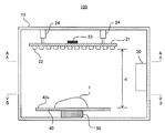
- FIG. It is sectional drawing which looked at the ultraviolet sterilizer 100 from the front.
- FIG. 3 is an AA arrow view of FIG. 2.
- FIG. 3 is a view taken along arrow BB in FIG. 2.
- FIG. It is sectional drawing which illustrates typically the ultraviolet sterilizer 200 which concerns on other one Embodiment of this invention.
- (A) is a top view of the deep ultraviolet surface light source 220.
- FIG. (B) is a side view of the deep ultraviolet surface light source 220. It is a flowchart explaining control flow S2 of the ultraviolet sterilizer 200.
- FIG. 1 is a schematic perspective view schematically illustrating an ultraviolet sterilizer 100 according to an embodiment of the present invention, and is a view seen through a housing 10 (described later).
- FIG. 2 is a cross-sectional view of the ultraviolet sterilizer 100 as viewed from the front.
- the ultraviolet sterilizer 100 includes a box-shaped housing 10 having a front surface 10a, a rear surface 10b, an upper surface 10c, a bottom surface 10d, side surfaces 10e and 10f, a deep ultraviolet light source 20 disposed in the vicinity of the upper surface 10c inside the housing 10, Arranged on the side of the bottom surface 10d of the control device 30 disposed inside the housing 10, the support base 40 for placing the object 1 to be sterilized, disposed near the bottom surface 10d inside the housing 10
- the driving unit 50 rotates the support base 40, and the input / output unit 60 is disposed outside the housing 10 (front surface 10a in FIG. 1).
- An openable / closable door 11 is provided on the front surface 10 a of the housing 10, and the sterilized body 1 can be taken in and out of the housing 10 by opening the door 11.
- the deep ultraviolet light source 20 is disposed in the housing 10 so as to face the mounting surface 40 a of the support base 40.
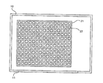
- FIG. 3 is an AA arrow view of FIG.
- the deep ultraviolet light source 20 includes a substrate 21 and a plurality of deep ultraviolet light emitting diodes 22, 22,... Arranged on the substrate 21 (hereinafter simply referred to as “deep ultraviolet light emitting diode 22”).
- a temperature sensor 23 for example, a thermocouple thermometer, etc.
- the deep ultraviolet light emitting diode 22 is a light emitting diode having an emission wavelength of 200 to 300 nm, preferably 220 to 270 nm.
- the deep ultraviolet light source 20 is fixed to the upper surface 10 c of the housing 10 via the actuator 24.
- the distance d between the sterilized object 1 and the deep ultraviolet light source 20 is adjusted by the operation of the actuator 24. As shown in FIG. 2, in the ultraviolet sterilization apparatus 100, the distance d is a distance from the deep ultraviolet light source 20 to the mounting surface 40 a of the support 40 (that is, from the surface of the sterilized body 1 to the deep ultraviolet light source 20. The maximum distance) is adopted.
- FIG. 4 is a view taken along the line BB in FIG. 2, and the support base 40 appears. As shown by arrow C in FIG. 4, the support base 40 is rotated by the driving means 50, and thereby, the irradiation amount of deep ultraviolet rays applied to the sterilized body 1 placed on the support base 40 is leveled. .
- the input / output means 60 is configured to transfer information input by the operator to the control device 30 and display the information transferred from the control device 30 toward the operator.
- Output means 60 at least, receive an input of information related to a predetermined value I 0 can transfer the information to the control unit 30 accepts an input of instruction to start sterilization control information that there was the instruction It can be transferred to the device 30. Further, information indicating that the sterilization process has been completed, transferred from the control device 30, can be displayed to the operator.
- a form provided with a display device such as a liquid crystal display and an input device such as a keyboard can be exemplified.
- the control device 30 is connected to the drive circuit of the deep ultraviolet light emitting diode 22, the temperature sensor 23, the actuator 24, the drive means 50, and the input / output means 60, and controls these operations.
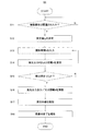
- FIG. 5 is a flowchart for explaining the control flow S1 of the ultraviolet sterilizer 100.
- FIG. 5 is also a flowchart for explaining an ultraviolet sterilization method according to an embodiment of the present invention.
- the control flow S1 has steps S11 to S18. The operation of the control device 30 will be described with reference to FIG.
- step S11 it is determined whether or not the object 1 to be sterilized is disposed on the mounting surface 40a of the support base 40. For this determination, for example, a weight sensor provided on the lower surface of the support base 40 can be used. For example, the operator may notify the control device 30 through the input / output means 60 that the operator has placed the sterilized body 1 on the support base 40. If a positive determination is made in step S11, the process proceeds to the next step S12.
- step S12 the integrated irradiation amount I 0 (unit: mJ / cm 2 ) of deep ultraviolet rays to be irradiated to the sterilized body 1 is determined.
- the control device 30 prompts the operator to select a specific microorganism to be killed or to select a general sterilization process via the input / output means 60. When a specific microorganism to be killed is selected, the control device 30 substitutes an irradiation amount at which 99% or more of the microorganism to be killed is killed into I 0 .
- the control device 30 includes a storage device, and a table in which specific microorganisms are associated with an irradiation amount at which 99% or more of the microorganisms die is recorded in the storage device.
- the control device 30 searches the table for the selected specific microorganism, reads the value of the dose associated with the microorganism, and substitutes it into I 0 . Further, when a general sterilization treatment is selected by the operator, an irradiation amount at which microorganisms generally found in the environment are sufficiently killed is substituted for I 0 .
- I 0 for example, a value determined within a range of 50.0 mJ / cm 2 or more, preferably 50 to 100 mJ / cm 2 can be adopted.
- a predetermined value I 0 of an integrated irradiation amount that can sufficiently sterilize these microorganisms is set in advance according to the type of the object to be sterilized. It may be determined and substituted for I 0 by selecting the type of the object to be sterilized.
- step S ⁇ b> 13 the control device 30 causes the operator to input a time (irradiation time) t during which the object to be sterilized is irradiated with deep ultraviolet rays via the input / output means 60.
- a time (irradiation time) t during which the object to be sterilized is irradiated with deep ultraviolet rays via the input / output means 60.
- step S14 the control device 30 calculates the light emission output P (unit: mW) of the deep ultraviolet light source 20 necessary for setting the integrated dose I to I 0 during the input irradiation time t.
- the accumulated dose I (unit: mJ / cm 2 ) of deep ultraviolet rays irradiated to the sterilized object 1 during the irradiation time t is the amount of deep ultraviolet rays per unit area at a distance d from the deep ultraviolet light source 20. It is given by integration of irradiation time t of irradiance (unit: mW / cm 2 ).
- the storage device provided in the control device 30 information on the dependence of the irradiance of deep ultraviolet rays per unit area on the distance from the deep ultraviolet light source 20 is recorded.
- the attenuation rate is calculated based on the distance d to the light source 20, and the necessary light emission output P is determined.
- the calculated light emission output P exceeds the maximum light emission output P MAX that the deep ultraviolet light source 20 can continuously exert, or a value obtained by multiplying P MAX by a preset safety factor (for example, 90%, preferably 80%). If so, the calculation of the light emission output P is attempted again assuming a shorter distance d within the adjustable range.
- the light emission output P equal to or less than the maximum light emission output P MAX is obtained, or the light emission output P is preset to the maximum light emission output P MAX of the deep ultraviolet light source 20 or P MAX for the shortest distance d within the adjustable range.
- the process proceeds to step S15.
- step S15 it is determined whether or not a solution of the light emission output P and the distance d that can be realized is obtained. If an affirmative determination is made in step S15, the process proceeds to step S16. When a negative determination is made in step S15, the control device 30 indicates that sufficient sterilization cannot be performed with the irradiation time t previously input via the input / output means 60, and the minimum required irradiation time t. 'Is notified to the operator, and the process returns to step S13 to prompt the operator to input a longer irradiation time t or to confirm that the irradiation time is t'.
- step S16 the light emission output P and / or the distance d between the sterilized object 1 and the deep ultraviolet light source 20 are adjusted.
- the irradiance of deep ultraviolet rays at a position away from the deep ultraviolet light source 20 by the distance d is the distance d, the emission intensity and directivity of each deep ultraviolet light emitting diode 22, and the arrangement method (arrangement pattern) of the deep ultraviolet light emitting diodes 22 It depends on various factors. Therefore, when performing the above adjustment, the relationship between the light emission output P at each distance d and the irradiance (unit: mW / cm 2 ) at the irradiated surface is examined for each actual machine (or an apparatus having the same specifications). , Based on the relationship.
- step S16 When adjusting the light emission output P and / or the distance d in step S16, continuous light emission or pulse light emission is performed continuously at an output P of 90%, preferably 80% of the maximum light emission output P MAX without adjusting d. It is preferable to adjust P so that the integrated dose I becomes I 0 within the upper limit of the input irradiation time t (rather than increasing P and shortening t). .
- the control of P can be performed by controlling the forward current flowing through the deep ultraviolet light-emitting diode. The control of the forward current is not particularly limited.
- a battery having a voltage of about 1.5 to 15 V is used as a power source as in a portable ultraviolet sterilizer, 10 mA to 1000 mA, preferably It is preferable to use a light-emission control circuit using a step-up DC-DC converter or a charge pump that can flow a forward current of 50 mA to 500 mA.
- a sufficient sterilizing effect can be achieved with a short irradiation time (eg, within 10 minutes, preferably within 1 minute) Can be obtained.
- JP-A-2005-93566, JP-A-2007-97251, and JP-A-2010-4691 can be applied to the light emission control circuit. If the adjustment of the distance d is necessary in addition to the adjustment of the output P, the distance d is adjusted to the value calculated in step S14. That is, the actuator 24 is driven to adjust the distance d so that the actual value of the distance d is equal to the value calculated in step S14. Thus, after the output P and / or the distance d is adjusted, the process proceeds to step S17.
- step S17 deep ultraviolet light is irradiated from the deep ultraviolet light source 20 for the irradiation time t with the light emission output P already calculated in step S14.
- the storage device of the control device 30 information on the dependency of the light emission output P of the deep ultraviolet light source 20 on the forward current and the element temperature of the deep ultraviolet light emitting diodes 22, 22,.
- the control device 30 controls (finely adjusts) the forward current flowing through the deep ultraviolet light emitting diodes 22, 22,... Based on the element temperature information detected by the temperature sensor 23.
- the light emission output P of the deep ultraviolet light source 20 is controlled to be maintained at the light emission output value already calculated in step S14.
- the control device 30 operates the driving means 50 so as to level the irradiation amount of the deep ultraviolet light irradiated to the sterilized body 1 to support the support base. Rotate 40.
- the control device 30 finishes supplying the current to the ultraviolet light emitting diodes 22, 22,. Move to.
- step S18 the control device 30 notifies the operator that the sterilization process has been completed via the input / output means.
- the operator can open the door 11 and take out the sterilized body 1 that has been sterilized from the inside of the housing 10.
- control device 30 examples include a storage device in which information and a processing flow necessary for the above processing are recorded, and an arithmetic device such as a microprocessor.
- the ultraviolet sterilizer 100 in the form of rotating the support base 40 in order to level the irradiation amount of deep ultraviolet light is exemplified, but the present invention is not limited to this form. It is also possible to provide an ultraviolet sterilization apparatus having a drive means for rotating the deep ultraviolet light source relative to the support base so as to level the irradiation amount of the deep ultraviolet light onto the body to be sterilized.
- the input / output means 60 is provided, and in step S12, the predetermined value I 0 is determined based on the microorganism to be killed, or a value sufficient for general sterilization is set to I 0.
- the present invention is not limited to this form. Sufficient value to common sterilization leave initialized to I 0, it is also possible to ultraviolet sterilizer forms of unnecessary input I 0, the microorganism to kill designated by the operator it is also possible to response value as an ultraviolet sterilizer in the form of only set to I 0.
- the ultraviolet sterilization apparatus 100 of the form which controls the light emission output P of the deep ultraviolet light source 20 based on element temperature was illustrated, this invention is not limited to the said form.
- the distance d between the deep ultraviolet light source 20 and the sterilized body 1 and / or the deep ultraviolet light source is set so that the integrated irradiation amount I within the predetermined irradiation time t becomes the predetermined value I 0 .
- the ultraviolet sterilization apparatus 100 and the ultraviolet sterilization method of the form which controls the light emission output P were illustrated, this invention is not limited to the said form.
- integrated irradiation dose I in the irradiation time t to a predetermined value I 0, and the ultraviolet sterilizer and ultraviolet sterilization method embodiment for controlling the irradiation time t It is also possible.
- priority is given to performing irradiation for a preset irradiation time t (seconds), but priority is given to shortening the actual irradiation time, and irradiation is performed at as high an output as possible.
- the distance d may also be adjusted so that the integrated dose I becomes I 0 in the shortest time, and irradiation may be terminated at that time. At this time, it is preferable to notify the operator of the end of irradiation by sound or the like.
- the ultraviolet sterilization apparatus 100 having the deep ultraviolet light source 20 shown in FIG. 3 as the deep ultraviolet light source is exemplified, but the present invention is not limited to this form.
- the deep ultraviolet light source an ultraviolet sterilization apparatus having a deep ultraviolet light source 220 shown in FIG.
- the deep ultraviolet light source 20 may be installed on any one of the front surface 10a, the rear surface 10b, the side surfaces 10e and 10f other than the upper surface 10c, and may be installed on a plurality of surfaces.
- the support base 40 may be made of an ultraviolet transmissive material, and the deep ultraviolet light source 20 may be disposed on the bottom surface 10d.
- the mode in which the support base 40 is rotated to level the irradiation amount of the deep ultraviolet rays irradiated to the sterilized body 1 is adopted, but the leveling means is not limited to this.
- the support base may be slid back and forth, or the deep ultraviolet light source 20 may be moved without moving the object to be sterilized.
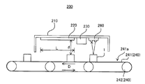
- FIG. 6 is a cross-sectional view schematically illustrating an ultraviolet sterilizer 200 according to another embodiment of the first aspect of the present invention.
- the ultraviolet sterilization apparatus 200 is an embodiment of the second aspect of the present invention, which is disposed on the conveyor 240 on which the object 1 to be sterilized is moved, and above the conveyor 240 so as to face the conveyor 240.
- the deep ultraviolet surface light source 220, the control device 230, the distance sensor 260 arranged on the upstream side of the conveyor 240 of the deep ultraviolet surface light source 220, the deep ultraviolet surface light source 220, the distance sensor 260, and the control device 230 are placed at predetermined positions. And a housing 210 to be held.
- the conveyor 240 includes an endless belt 241 having a placement surface 241a on which the object 1 to be sterilized is placed, and a driving device 242 that drives the belt 241 in the direction of arrow D in FIG.
- the driving device 242 is connected to the control device 230.
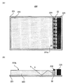
- FIG. 7A is a plan view of the deep ultraviolet surface light source 220
- FIG. 7B is a side view of the deep ultraviolet surface light source 220
- the deep ultraviolet surface light source 220 includes a substrate 221, a light guide plate 223 disposed on the substrate 221, and a plurality of deep ultraviolet light emitting diodes 22 arranged on the substrate 221 so as to face the end portion 223a of the light guide plate 223.
- 22,..., Temperature sensors 224, 224,... for example, thermocouple thermometers, etc .; hereinafter simply referred to as “temperature sensor 224” for measuring the element temperature of the deep ultraviolet light-emitting diode 22,
- a current control device 225 for controlling the forward current flowing through the light emitting diode.
- Deep ultraviolet light emitted from the deep ultraviolet light emitting diode 22 and incident into the light guide plate 223 from the end 223a propagates through the light guide plate 223 while being totally reflected as indicated by an arrow E in FIG.
- the light exits from the light exit surface 223b of the optical plate 223.
- the deep ultraviolet surface light source 220 is disposed such that the light exit surface 223b of the light guide plate 223 faces the placement surface 241a of the conveyor 240.
- the plurality of deep ultraviolet light-emitting diodes 22 are, for example, disclosed in Japanese Patent No. 5591305, “a plurality of ultraviolet light-emitting elements on the side surface of a cylindrical or polygonal column base, and the light of each ultraviolet light-emitting element.
- An ultraviolet light emitting element-arranged substrate which is arranged so that its axis passes through the central axis of the cylindrical or polygonal column-shaped substrate so that ultraviolet rays are emitted radially with respect to the central axis, and an ultraviolet transmissive material
- the cover is airtightly attached to the ultraviolet light emitting element arrangement substrate so as to cover the ultraviolet light emitting element arrangement substrate and enclose an inert gas or dry air therein.
- An ultraviolet light emitting module characterized in that a cooling medium flow path is formed inside the cylindrical or polygonal column base and the cooling medium is circulated through the cooling medium flow path. It is also possible to use as Yuru ". By using such a module, it is possible to increase the intensity of ultraviolet rays and keep the element temperature constant.
- the current control device 225 is connected to the temperature sensor 224, the deep ultraviolet light emitting diode 22, and the control device 230.
- the current control device 225 receives information on the element temperature of the deep ultraviolet light emitting diode 22 from the temperature sensor 24.
- the current control device 225 receives information on the distance d from the light output surface 223b of the light guide plate 223 of the deep ultraviolet surface light source 220 to the sterilized body 1 from the control device 230, and at a position away from the light output surface 223b by the distance d.
- Information on the irradiance (unit: mW / cm 2 ) of deep ultraviolet rays to be achieved is received.
- the irradiance of deep ultraviolet rays at a position away from the light exit surface 223b by the distance d depends on the distance d, the emission intensity of the deep ultraviolet light emitting diode 22, the characteristics of the waveguide plate, and the like.
- the emission intensity of the deep ultraviolet light emitting diode 22 depends on the forward current flowing through the deep ultraviolet light emitting diode 22 and the element temperature of the deep ultraviolet light emitting diode 22.
- the current control device 225 includes a storage device and an arithmetic device, and the storage device of the current control device 225 includes the irradiance of deep ultraviolet rays, the distance d and deep ultraviolet light emission at a position away from the light exit surface 223b by the distance d.
- the relationship between the emission intensity of the diode 22 is recorded as a first function, and the relationship between the emission intensity of the deep ultraviolet light-emitting diode 22, the forward current and the element temperature is recorded as a second function.
- the current control device 225 receives the information on the distance d from the light exit surface 223b to the sterilized body 1 received from the control device 230, and the deep ultraviolet irradiance to be achieved at a position away from the light exit surface 223b by the distance d. From the information, the required emission intensity of the deep ultraviolet light emitting diode 22 is calculated using the first function.
- the forward current is calculated, and the deep ultraviolet light emitting diode 22 is caused to emit light with the calculated forward current. While the deep ultraviolet light emitting diode 22 is caused to emit light, the current control device 225 continues to monitor the element temperature information received from the temperature sensor 24 and keeps the light emission intensity of the deep ultraviolet light emitting diode 22 at the required light emission intensity calculated previously. As described above, the forward current is controlled using the second function.
- the distance sensor 260 is disposed above the conveyor 240 and on the upstream side of the conveyor 240 with respect to the deep ultraviolet surface light source 220 so as to face the placement surface 241 a of the conveyor 240.
- the distance sensor 260 performs both detection of the sterilized body 1 and measurement of the distance to the sterilized body 1.
- the distance sensor 260 measures the distance to the sterilized body 1 placed on the placement surface 241 a of the conveyor 240, and transfers the measurement result information to the control device 230.
- a distance sensor 260 for example, a known distance sensor such as an ultrasonic distance sensor, an infrared distance sensor, or a laser distance sensor can be employed without any particular limitation.
- the control device 230 uses the distance information received from the distance sensor 260 as the light exit surface of the light guide plate 223 of the deep ultraviolet surface light source 220 when the object 1 is moved below the light guide plate 223 of the deep ultraviolet surface light source 220. It converts into the distance d from 223b to the to-be-sterilized body 1.
- the control device 230 is connected to the current control device 225 of the deep ultraviolet surface light source 220, the distance sensor 260, and the drive device 242 of the conveyor 240, and controls these operations.
- FIG. 8 is a flowchart illustrating the control flow S2 of the ultraviolet sterilizer 200.
- FIG. 8 is also a flowchart for explaining an ultraviolet sterilization method according to another embodiment of the present invention.
- the control flow S2 has steps S21 to S28. The operation of the control device 230 will be described with reference to FIG.
- step S21 driving of the conveyor 240 is started, and the process proceeds to step S22.
- step S ⁇ b> 22 it is determined whether the sterilized body 1 has been transferred below the distance sensor 260. This determination can be made by detecting a change that occurs in the distance information received by the control device 230 from the distance sensor 260 that is disposed facing the placement surface 241a of the conveyor 240. If a positive determination is made in step S22, the process proceeds to the next step S23. If a negative determination is made in step S22, the process returns to step S21.
- the distance sensor 260 measures the distance to the sterilized object 1, and transfers the measurement result to the control device 230.
- the control device 230 receives the information of the distance measurement result from the distance sensor 260 and, based on the information, the deep ultraviolet surface light source 220 and the object to be sterilized when the sterilized body 1 comes to the irradiation region below the deep ultraviolet surface light source 220.
- the distance to the sterilized body 1 (that is, the distance from the light exit surface 223b of the light guide plate 223 to the sterilized body 1) d is calculated.
- step S24 the control device 230 determines the value of the accumulated amount of deep ultraviolet rays I 0 (unit: mJ / cm 2 ) to be irradiated to the sterilized object 1, and the value of the distance d calculated in step S23. Based on the above, the irradiation time t necessary for performing sufficient sterilization with deep ultraviolet rays on the sterilized object 1 is calculated.
- the ultraviolet sterilizer 200 is configured to perform a sterilization treatment that sufficiently kills microorganisms generally found in the environment, and employs a value of, for example, 50.0 mJ / cm 2 or more as I 0 .
- the control device 230 has at least a storage device and an arithmetic unit, and the storage device stores a value of I 0 and a light emission output P (unit: mW) to be exhibited by the deep ultraviolet light source 220. .
- the irradiance (unit: mW / cm 2 ) of deep ultraviolet light at a position away from the deep ultraviolet surface light source 220 by the distance d depends on the light emission output P (unit: mW) of the deep ultraviolet light source 220 and the distance d.
- the storage device of the control device 230 stores deep ultraviolet light at a position away from the deep ultraviolet surface light source 220 by a distance d when the deep ultraviolet surface light source 220 is driven with a predetermined light emission output P recorded in the storage device.
- the relationship between irradiance and distance d is recorded as a function.
- the control device 230 uses this function to calculate the irradiance of deep ultraviolet rays on the surface of the sterilized object 1 from the previously calculated distance d, and to achieve the integrated dose I 0 from the calculated irradiance.
- the required time t required for the calculation is calculated.
- step S25 the control device 230 starts from the required time t calculated in step S24, the speed at which the sterilized body 1 should be moved while the sterilized body 1 is irradiated with deep ultraviolet rays, that is, the movement of the conveyor 240. Calculate the speed.
- the length L (see FIG. 6) of the section on the conveyor 240 irradiated with deep ultraviolet light having a constant intensity from the deep ultraviolet surface light source 220 is recorded.
- step S ⁇ b> 26 the control device 230 drives the conveyor 240 to move the object to be sterilized 1 to the upstream end (see FIG. 6) of the section irradiated with deep ultraviolet light having a constant intensity from the deep ultraviolet light source 220. .
- step S27 the control device 230 transfers the value of the distance d and the value of irradiance to be achieved at a position away from the deep ultraviolet surface light source 220 by the distance d to the current control device 225 of the deep ultraviolet surface light source 220. Then, an instruction to start deep ultraviolet irradiation is sent. At the same time, the control device 230 controls the driving device 242 of the conveyor 240 so that the moving speed v of the conveyor 240 becomes the value calculated in step S25. When the deep ultraviolet irradiation for the predetermined time t is completed, the process proceeds to step S28.
- step S28 the control device 230 further operates the conveyor 240 to move the sterilized body 1 to the downstream side of the deep ultraviolet surface light source 220.
- control device 230 a mode having a storage device in which information and a processing flow necessary for the above processing are recorded, and an arithmetic device such as a microprocessor can be exemplified.
- the ultraviolet light sterilizer is configured to achieve the predetermined integrated irradiation amount I 0 by fixing the light emission output P of the deep ultraviolet surface light source 220 and controlling the irradiation time t by the moving speed of the conveyor 240.
- 200 and the ultraviolet sterilization method were illustrated, this invention is not limited to the said form.
- the moving speed of the conveyor that is, the irradiation time t
- the predetermined integrated irradiation amount I 0 is achieved while the object to be sterilized passes under the deep ultraviolet light source (that is, the region facing the deep ultraviolet light source).
- an ultraviolet sterilization apparatus and an ultraviolet sterilization method that control the light emission output P of the deep ultraviolet light source may be used.
- the moving speed of the conveyor (that is, the irradiation time t) is fixed, and the emission output P of the deep ultraviolet light source that achieves a predetermined integrated irradiation amount I 0 while the object to be sterilized passes under the deep ultraviolet light source.
- the predetermined integrated dose I 0 is achieved only by controlling the light output P without changing the moving speed of the conveyor. If the calculated value of the light emission output P exceeds the realizable maximum value, the predetermined integrated irradiation amount is obtained by the realizable light emission output P by lowering the moving speed of the conveyor and increasing the irradiation time t. it is also possible to ultraviolet sterilizer and ultraviolet sterilization method according to accomplish I 0.
- the UV sterilization apparatus 200 in which the control device 230 indirectly controls the deep UV light emitting diode 22 via the current control device 225 of the deep UV surface light source 220 is illustrated.
- the form is not limited.
- the deep ultraviolet light emitting diode 22 and the temperature sensor 224 are connected to the control device 230, and the control device 230 may be an ultraviolet sterilization device that directly reads out the measured value from the temperature sensor 224 and drives the deep ultraviolet light emitting diode 22. Is possible.
- the deep ultraviolet surface light source 220 has exemplified the form having the temperature sensor 224 for measuring the element temperature of the deep ultraviolet light emitting diode 22, but the ultraviolet surface light source of the present invention is not limited to this form.
- an ultraviolet surface light source having a temperature adjusting means for example, a Peltier element for controlling the element temperature of the deep ultraviolet light emitting diode 22 may be used.
Landscapes
- Health & Medical Sciences (AREA)
- Public Health (AREA)
- Epidemiology (AREA)
- Life Sciences & Earth Sciences (AREA)
- Animal Behavior & Ethology (AREA)
- General Health & Medical Sciences (AREA)
- Veterinary Medicine (AREA)
- Physics & Mathematics (AREA)
- General Physics & Mathematics (AREA)
- Spectroscopy & Molecular Physics (AREA)
- Electromagnetism (AREA)
- Apparatus For Disinfection Or Sterilisation (AREA)
- Led Device Packages (AREA)
Abstract
Description
近年、従来の青色発光ダイオードや紫外線発光ダイオードよりもさらに短波長の紫外線を発光する深紫外発光ダイオードの開発が進んでおり、該深紫外線発光ダイオードを用いて殺菌を行うことが考えられる。しかし、深紫外線発光ダイオードは従来の青色又は紫外線発光ダイオードよりも発光強度が低いため、長時間光照射を行っても被殺菌物に付着した微生物を十分に死滅させることができないおそれがある。
(1)被殺菌体に深紫外線を照射する時間として定義される照射時間:t(単位:秒)、
(2)被殺菌体と深紫外線光源との間の距離:d(単位:cm)、および
(3)深紫外線光源の発光出力:P(単位:mW)
から選ばれる1以上を制御して、照射時間内に被殺菌体に対して照射される深紫外線の積算照射量I(単位:mJ/cm2)が予め定めた所定値I0となるようにするものであることを特徴とする、紫外線殺菌装置である。
当該形態において、制御手段は、距離センサによって測定された距離dに基づいて、照射時間tおよび/または深紫外線光源の発光出力Pを制御することが好ましい。
当該形態において、紫外線殺菌装置は、死滅させるべき微生物を決定するための入力手段をさらに有することが好ましく、また、所定値I0が、死滅させるべき微生物の99%以上が死滅する照射量であることが好ましい。
(1)被殺菌体に深紫外線を照射する時間として定義される照射時間:t(単位:秒)、
(2)被殺菌体と前記深紫外線光源との間の距離:d(単位:cm)、および
(3)深紫外線光源の発光出力:P(単位:mW)
から選ばれる1以上を制御して、照射時間内に被殺菌体に対して照射される深紫外線の積算照射量I(単位:mJ/cm2)が予め定めた所定値I0を満足するように、深紫外線光源から当該照射時間の間、発光出力Pで、被殺菌体に深紫外線を照射する工程を有することを特徴とする、紫外線殺菌方法である。
ステップS16における発光出力P及び/又は距離dの調整に際しては、dを調整せずに、最大発光出力PMAXの90%、好ましくは80%の出力Pで連続的に連続発光又はパルス発光を行うことを優先するようにすると共に、(Pを大きくしてtを短くするよりも)入力された照射時間tの上限内で積算照射量IがI0となるようにPを調整することが好ましい。Pの制御は、深紫外線光源の発光出力Pの制御は、深紫外線発光ダイオードに流す順方向電流を制御することにより行うことができる。順方向電流の制御は、特に限定されるものではないが、ポータブル型の紫外線殺菌装置のように、電源として電圧が1.5~15V程度のバッテリーを用いる場合には、10mA~1000mA、好ましくは50mA~500mAの順方向電流を流すことができるような、昇圧DC-DCコンバータ又はチャージポンプ用いた発光制御回路により行うことが好ましい。こうすることにより、使用する深紫外線発光ダイオードの性能にもよるが、比較的低電圧のバッテリーを電源として用いても短い照射時間(たとえば10分以内、好ましくは1分以内)で十分な殺菌効果を得ることが可能となる。なお、上記発光制御回路には、例えば特開2005-93566号公報、特開2007-97251号公報および特開2010-4691号公報に記載された技術を適用可能である。
そして、出力Pの調整以外に距離dの調整が必要である場合には、距離dが、ステップS14において算出された値に調整される。すなわち、距離dの実際の値がステップS14において算出された値に等しくなるようにアクチュエータ24が駆動されて距離dが調整される。このようにして、出力P及び/又は距離dが調整した後、処理をステップS17に移す。
100、200 紫外線殺菌装置
10、210 筐体
10a 前面
10b 後面
10c 上面
10d 底面
10e、10f 側面
11 ドア
20 深紫外線光源
21、221 基板
22 深紫外線発光ダイオード
23、224 温度センサ
24 アクチュエータ
30、230 制御装置
40 支持台
50 駆動手段
60 入出力手段
220 深紫外線面光源
223 導光板
223a (導光板の)端部
223b (導光板の)出光面
225 電流制御装置
240 コンベア
241 ベルト
241a (コンベアの)載置面
242 駆動装置
260 距離センサ
Claims (21)
- 一以上の深紫外線発光ダイオードを有し被殺菌体に向けて深紫外線を出射する、深紫外線光源と、
制御手段とを有し、
該制御手段は、
(1)前記被殺菌体に深紫外線を照射する時間として定義される照射時間:t(単位:秒)、
(2)前記被殺菌体と前記深紫外線光源との間の距離:d(単位:cm)、および
(3)前記深紫外線光源の発光出力:P(単位:mW)
から選ばれる1以上を制御して、前記照射時間内に前記被殺菌体に対して照射される深紫外線の積算照射量I(単位:mJ/cm2)が予め定めた所定値I0となるようにするものであることを特徴とする、紫外線殺菌装置。 - 前記深紫外線光源の発光出力Pの制御を、前記深紫外線発光ダイオードに流す順方向電流を制御することにより行うことを特徴とする、
請求項1に記載の紫外線殺菌装置。 - 前記深紫外線発光ダイオードの素子温度を測定する温度センサをさらに有し、
前記制御手段が、前記温度センサによって測定された前記深紫外線発光ダイオードの素子温度に基づいて、前記深紫外線光源の発光出力Pを制御する、
請求項1又は2に記載の紫外線殺菌装置。 - 前記制御手段は、所定の照射時間t内における前記積算照射量Iが前記所定値I0となるように、前記深紫外線光源と前記被殺菌体との間の距離dおよび/または前記深紫外線光源の発光出力Pを制御する、
請求項1~3のいずれかに記載の紫外線殺菌装置。 - 前記深紫外線光源と前記被殺菌体との間の距離dを測定する距離センサをさらに有する、
請求項1~4のいずれかに記載の紫外線殺菌装置。 - 前記制御手段は、前記距離センサによって測定された距離dに基づいて、前記照射時間tおよび/または前記深紫外線光源の発光出力Pを制御する、
請求項5に記載の紫外線殺菌装置。 - 前記所定値I0が、50.0mJ/cm2以上の値である、請求項1~6のいずれかに記載の紫外線殺菌装置。
- 前記所定値I0が、死滅させるべき微生物に基づいて定められる照射量である、請求項1~6のいずれかに記載の紫外線殺菌装置。
- 前記死滅させるべき微生物を決定するための入力手段をさらに有する、請求項8に記載の紫外線殺菌装置。
- 前記所定値I0が、前記死滅させるべき微生物の99%以上が死滅する照射量である、請求項8又は9に記載の紫外線殺菌装置。
- 前記深紫外線光源が、基板と、該基板上に配列された複数の前記深紫外線発光ダイオードとを有する、
請求項1~10のいずれかに記載の紫外線殺菌装置。 - 筐体と、
前記筐体内に配置された、前記被殺菌体を載置するための支持台と
をさらに有し、
前記深紫外線光源は、前記支持台と対向するように前記筐体内に配置されており、
前記被殺菌体に照射される深紫外線の照射量を平準化するように前記深紫外線光源を前記支持台に対して回転させる駆動手段をさらに有する、
請求項1~11のいずれかに記載の紫外線殺菌装置。 - 筐体と、
前記筐体内に配置された、前記被殺菌体を載置するための支持台と
をさらに有し、
前記深紫外線光源は、前記支持台と対向するように前記筐体内に配置されており、
前記被殺菌体に照射される深紫外線の照射量を平準化するように前記支持台を前記深紫外線光源に対して回転させる駆動手段をさらに有する、
請求項1~11のいずれかに記載の紫外線殺菌装置。 - 前記深紫外線光源が、
導光板と、
前記導光板の端部に配列された、複数の前記深紫外線発光ダイオードと
を有する、請求項1~10のいずれかに記載の紫外線殺菌装置。 - 前記被殺菌体を載置して移動するコンベアをさらに有し、
前記深紫外線光源は、前記コンベアに対向して配置されており、
前記照射時間tの制御を、前記コンベアの移動速度を制御することにより行う、
請求項1~11及び請求項14のいずれかに記載の紫外線殺菌装置。 - 導光板と、
前記導光板の端部に配列された、複数の深紫外線発光ダイオードと、
前記深紫外線発光ダイオードの素子温度を測定する温度センサ、または、前記深紫外線発光ダイオードの素子温度を制御する温調手段と、
前記深紫外線発光ダイオードに流す順方向電流を制御する電流制御装置と、
を有し、
前記電流制御装置は、前記深紫外線発光ダイオードの素子温度に基づいて、前記導光板から照射される深紫外線の、前記導光板から所定の距離だけ離れた位置における照射強度が、所定の値となるように、前記深紫外発光ダイオードに流す順方向電流を制御することを特徴とする、紫外線面光源。 - 一以上の深紫外線発光ダイオードを有し被殺菌体に向けて深紫外線を出射する深紫外線光源を用いて被殺菌体を殺菌する方法であって、
(1)前記被殺菌体に深紫外線を照射する時間として定義される照射時間:t(単位:秒)、
(2)前記被殺菌体と前記深紫外線光源との間の距離:d(単位:cm)、および
(3)前記深紫外線光源の発光出力:P(単位:mW)
から選ばれる1以上を制御して、前記照射時間内に前記被殺菌体に対して照射される深紫外線の積算照射量I(単位:mJ/cm2)が予め定めた所定値I0を満足するように、前記深紫外線光源から前記照射時間tの間、前記発光出力Pで、前記被殺菌体に深紫外線を照射する工程を有することを特徴とする、紫外線殺菌方法。 - 前記被殺菌体に対して照射すべき深紫外線の積算照射量I0(単位:mJ/cm2)を決定する工程と、
前記照射時間tを設定する工程と、
前記照射時間tの間に前記被殺菌体に対して照射される深紫外線の積算照射量I(単位:mJ/cm2)を前記積算照射量I0とするために必要な前記発光出力Pを算出する工程と、
前記発光出力P、及び/又は、前記距離dを調整する工程と、
前記深紫外線光源から、前記発光出力Pで、前記照射時間tの間、前記被殺菌体に深紫外線を照射する工程と、
を有する、請求項17に記載の紫外線殺菌方法。 - 前記被殺菌体に対して照射すべき深紫外線の積算照射量I0(単位:mJ/cm2)を決定する工程と、
前記発光出力P、及び、前記距離dに基づいて、前記深紫外光源から発光出力Pで深紫外線を照射したときの前記被殺菌体に対して照射される深紫外線の積算照射量I(単位:mJ/cm2)が前記積算照射量I0となるために必要な前記照射時間tを算出する工程と、
前記深紫外線光源から、前記発光出力Pで、前記照射時間tの間、前記被殺菌体に深紫外線を照射する工程と、
を有する、請求項17に記載の紫外線殺菌方法。 - 前記深紫外線光源は、前記被殺菌体が載置されるコンベアに対向して配置されており、
前記被殺菌体が載置されたコンベアの駆動を開始する工程と、
前記距離dを測定する工程と、
前記発光出力P、及び、前記測定された距離dに基づいて、前記深紫外光源から発光出力Pで深紫外線を照射したときの前記被殺菌体に対して照射される深紫外線の積算照射量I(単位:mJ/cm2)が前記所定値I0となるために必要な前記照射時間tを算出する工程と、
前記照射時間tに基づいて、前記被殺菌体に深紫外線を照射している間に前記被殺菌体を移動させるべき速度を算出する工程と、
前記算出された速度で前記コンベアを駆動しながら、前記深紫外線光源から前記被殺菌体に発光出力Pで深紫外線を照射する工程と、
を有する、請求項17に記載の紫外線殺菌方法。 - 前記深紫外線光源は、前記被殺菌体が載置されるコンベアに対向して配置されており、
前記被殺菌体が載置されたコンベアを所定の速度で駆動する工程と、
前記距離dを測定する工程と、
前記被殺菌体が前記深紫外線光源と対向する領域を通過する間に前記被殺菌体に対して照射される深紫外線の積算照射量I(単位:mJ/cm2)が前記所定値I0となるために必要な前記発光出力Pを算出する工程と、
前記所定の速度で前記コンベアを駆動しながら、前記深紫外線光源から前記被殺菌体に発光出力Pで深紫外線を照射する工程と、
を有する、請求項17に記載の紫外線殺菌方法。
Priority Applications (3)
| Application Number | Priority Date | Filing Date | Title |
|---|---|---|---|
| US15/561,838 US20180110890A1 (en) | 2015-03-31 | 2016-03-18 | Ultraviolet light sterilizer |
| KR1020177019284A KR20170134969A (ko) | 2015-03-31 | 2016-03-18 | 자외선 살균 장치 |
| CN201680012834.1A CN107405415A (zh) | 2015-03-31 | 2016-03-18 | 紫外线杀菌装置 |
Applications Claiming Priority (2)
| Application Number | Priority Date | Filing Date | Title |
|---|---|---|---|
| JP2015074477A JP6151736B2 (ja) | 2015-03-31 | 2015-03-31 | 紫外線殺菌装置 |
| JP2015-074477 | 2015-03-31 |
Publications (1)
| Publication Number | Publication Date |
|---|---|
| WO2016158524A1 true WO2016158524A1 (ja) | 2016-10-06 |
Family
ID=57006730
Family Applications (1)
| Application Number | Title | Priority Date | Filing Date |
|---|---|---|---|
| PCT/JP2016/058818 Ceased WO2016158524A1 (ja) | 2015-03-31 | 2016-03-18 | 紫外線殺菌装置 |
Country Status (6)
| Country | Link |
|---|---|
| US (1) | US20180110890A1 (ja) |
| JP (1) | JP6151736B2 (ja) |
| KR (1) | KR20170134969A (ja) |
| CN (1) | CN107405415A (ja) |
| TW (1) | TW201701907A (ja) |
| WO (1) | WO2016158524A1 (ja) |
Cited By (2)
| Publication number | Priority date | Publication date | Assignee | Title |
|---|---|---|---|---|
| CN111511409A (zh) * | 2017-10-11 | 2020-08-07 | 香港科技大学 | 用于快速表面消毒的异步间歇性光照 |
| US20210228752A1 (en) * | 2018-07-04 | 2021-07-29 | Sing-Hong Stefan Chang | Method and Device for Cleaning and Disinfecting Objects |
Families Citing this family (45)
| Publication number | Priority date | Publication date | Assignee | Title |
|---|---|---|---|---|
| EP4682463A3 (en) * | 2015-06-26 | 2026-06-03 | Seoul Viosys Co., Ltd. | Sterilizing apparatus |
| US10694681B2 (en) * | 2017-03-09 | 2020-06-30 | Ryan Joseph Topps | Closed apparatus for irradiating plants and produce |
| KR20190090959A (ko) * | 2018-01-26 | 2019-08-05 | 서울바이오시스 주식회사 | 유체 처리 장치 |
| US10959441B2 (en) | 2018-04-18 | 2021-03-30 | Xenon Corporation | Ultraviolet treatment of food products to kill microorganisms while retaining fruit bloom |
| TWI732138B (zh) * | 2018-09-28 | 2021-07-01 | 光磊科技股份有限公司 | 紫外線led封裝結構 |
| CN109771678B (zh) * | 2019-02-01 | 2021-04-09 | 苏州智货电子科技有限公司 | 杀菌装置和杀菌方法 |
| CN111558054A (zh) * | 2019-02-14 | 2020-08-21 | 通用电气照明解决方案有限公司 | 照明消杀系统和通过该系统对照射面进行消毒杀菌的方法 |
| WO2020198138A1 (en) * | 2019-03-22 | 2020-10-01 | Xenon Corporation | Flash lamp system for disinfecting conveyors |
| JP7339522B2 (ja) * | 2019-09-30 | 2023-09-06 | ダイキン工業株式会社 | 空気調和機 |
| WO2021179474A1 (zh) * | 2020-03-13 | 2021-09-16 | 浙江维尔科技有限公司 | 一种紫外照射剂量的自动控制方法和紫外消毒杀菌设备 |
| JP6774584B1 (ja) * | 2020-03-27 | 2020-10-28 | 東京瓦斯株式会社 | 光照射システム |
| US11992565B2 (en) * | 2020-04-03 | 2024-05-28 | Redi Technology, Inc. | Food or beverage container sanitizing system |
| US20210308299A1 (en) * | 2020-04-07 | 2021-10-07 | Torkild Benn Vennesland | Disinfecting and/or sterilizing device and methods of making and using the same |
| CN113559293B (zh) * | 2020-04-28 | 2023-04-25 | 深圳华芯集成电路设计有限公司 | Uvc紫外线消毒装置 |
| SE2050535A1 (en) * | 2020-05-07 | 2021-11-08 | Uvivo Ab | A safety device for automatic adjustment of uvc radiation |
| US11712488B2 (en) | 2020-06-11 | 2023-08-01 | 1Lss, Inc | Method and apparatus for rapid disinfection of personal items |
| US11033645B1 (en) * | 2020-06-11 | 2021-06-15 | 1Lss, Inc | Apparatus for rapid disinfection of personal items |
| JP2022001095A (ja) * | 2020-06-19 | 2022-01-06 | 株式会社ファームロイド | 紫外線照射殺菌装置、紫外線照射殺菌システム及び紫外線照射殺菌方法 |
| JP7602781B2 (ja) * | 2020-07-30 | 2024-12-19 | カルテック株式会社 | 鮮度保持装置 |
| JP6948605B1 (ja) * | 2020-08-05 | 2021-10-13 | ウシオ電機株式会社 | 菌又はウイルスの不活化方法、菌又はウイルスの不活化装置 |
| US20230364283A1 (en) * | 2020-08-06 | 2023-11-16 | Germflare Aps | Decontamination device, decontamination assembly, decontamination system, and related methods |
| US12012288B1 (en) * | 2020-08-28 | 2024-06-18 | Robert Giovanni Verduzco | Conveyor belt sanitizer system |
| JP2022056334A (ja) * | 2020-09-29 | 2022-04-08 | 豊田合成株式会社 | 収容ボックス |
| WO2022113442A1 (ja) * | 2020-11-25 | 2022-06-02 | ウシオ電機株式会社 | 菌又はウイルスの不活化装置 |
| JPWO2022137920A1 (ja) * | 2020-12-23 | 2022-06-30 | ||
| CN114762518A (zh) * | 2021-01-15 | 2022-07-19 | 中国科学院理化技术研究所 | 连续式光动力杀菌系统 |
| KR102305150B1 (ko) * | 2021-02-26 | 2021-09-27 | 배연구 | 양말 살균장치 |
| WO2022190672A1 (ja) * | 2021-03-09 | 2022-09-15 | ウシオ電機株式会社 | 菌又はウイルスの不活化装置、菌又はウイルスの不活化システム |
| EP4295868A4 (en) | 2021-03-31 | 2024-08-07 | Daikin Industries, Ltd. | PROCESSING DEVICE, UV EMISSION DEVICE AND UV EMISSION METHOD |
| CN113117106A (zh) * | 2021-04-09 | 2021-07-16 | 厦门大学 | 一种基于深紫外的冷链货物全方位消毒装置 |
| US12161774B2 (en) | 2021-05-04 | 2024-12-10 | Sony Group Corporation | Apparatus and method for disinfection of object |
| CN117412808A (zh) * | 2021-06-03 | 2024-01-16 | 大金工业株式会社 | 紫外线照射装置 |
| KR102400993B1 (ko) * | 2021-11-17 | 2022-05-23 | 한국전광(주) | 휴대품 전용 자외선 살균장치 |
| CN114010830B (zh) * | 2021-11-22 | 2022-08-26 | 珠海格力电器股份有限公司 | 一种消毒控制方法、装置及紫外灯 |
| CN114185293B (zh) * | 2021-12-10 | 2022-08-30 | 无锡市智控科技有限公司 | 基于深紫外线的高效灭菌装置 |
| EP4194013A1 (en) * | 2021-12-13 | 2023-06-14 | B. Braun Melsungen AG | Uvc light disinfection device |
| CN114700007A (zh) * | 2022-04-14 | 2022-07-05 | 深圳信息职业技术学院 | 一种口罩再生设备 |
| US20230364280A1 (en) * | 2022-05-16 | 2023-11-16 | Ig Soo Kwon | System and method for suppressing bacterial or viral growth using a combination of lights |
| JP7875435B2 (ja) * | 2022-05-25 | 2026-06-18 | 東芝ライテック株式会社 | 照射装置、および食品の処理装置 |
| CN115624641A (zh) * | 2022-11-10 | 2023-01-20 | 昆明昆船逻根机场系统有限公司 | 一种机场行李底部表面病菌消杀装置及方法 |
| CN116139305B (zh) * | 2022-11-22 | 2024-08-23 | 珠海格力电器股份有限公司 | 一种砧板消毒机控制方法、装置及砧板消毒机 |
| US12151041B2 (en) | 2022-12-22 | 2024-11-26 | MSPLG of Florida, LLC | Condiment sterilization devices and systems |
| CN117717634A (zh) * | 2023-12-06 | 2024-03-19 | 北京卫星环境工程研究所 | 一种航天器部组件表面微生物消杀柜 |
| WO2025168240A1 (en) * | 2024-02-07 | 2025-08-14 | Tetra Laval Holdings & Finance S.A. | Sterilizing of opening devices of packages |
| CN120204435B (zh) * | 2025-05-28 | 2025-08-19 | 天大泽源(天津)智能设备有限公司 | 一种综合药品稳定性实验箱灭菌控制方法及系统 |
Citations (9)
| Publication number | Priority date | Publication date | Assignee | Title |
|---|---|---|---|---|
| JP2005095400A (ja) * | 2003-09-25 | 2005-04-14 | Matsushita Electric Works Ltd | 紫外線ランプ点灯装置 |
| JP2005312978A (ja) * | 2005-05-11 | 2005-11-10 | Uchihashi Estec Co Ltd | コンベア式殺菌装置 |
| JP2006110235A (ja) * | 2004-10-18 | 2006-04-27 | Masaaki Suzuki | 家庭用衛生化処理装置 |
| JP2010207278A (ja) * | 2009-03-06 | 2010-09-24 | Yamaguchi Univ | 表面殺菌方法およびその装置 |
| JP2010275840A (ja) * | 2009-06-01 | 2010-12-09 | Panasonic Electric Works Co Ltd | 衛生器具用の排水装置 |
| JP2011098156A (ja) * | 2009-11-09 | 2011-05-19 | Miura:Kk | 紫外線殺菌装置 |
| JP2014184430A (ja) * | 2014-02-17 | 2014-10-02 | Price Management Of Japan Co Ltd | 照射装置 |
| JP5651794B1 (ja) * | 2014-03-31 | 2015-01-14 | パナソニック株式会社 | 空気調和機 |
| JP2015027326A (ja) * | 2013-07-30 | 2015-02-12 | パナソニックIpマネジメント株式会社 | 殺菌装置 |
Family Cites Families (4)
| Publication number | Priority date | Publication date | Assignee | Title |
|---|---|---|---|---|
| JP2005185302A (ja) * | 2003-12-24 | 2005-07-14 | House Tec:Kk | 殺菌装置 |
| JP2010119777A (ja) * | 2008-11-21 | 2010-06-03 | Hoshino Ing Corp | キー入力装置の殺菌装置 |
| JP2012139457A (ja) * | 2011-01-06 | 2012-07-26 | Aichi Electric Co Ltd | 不透明液状物質の殺菌装置 |
| US9165756B2 (en) * | 2011-06-08 | 2015-10-20 | Xenex Disinfection Services, Llc | Ultraviolet discharge lamp apparatuses with one or more reflectors |
-
2015
- 2015-03-31 JP JP2015074477A patent/JP6151736B2/ja not_active Expired - Fee Related
-
2016
- 2016-03-18 US US15/561,838 patent/US20180110890A1/en not_active Abandoned
- 2016-03-18 KR KR1020177019284A patent/KR20170134969A/ko not_active Withdrawn
- 2016-03-18 CN CN201680012834.1A patent/CN107405415A/zh active Pending
- 2016-03-18 WO PCT/JP2016/058818 patent/WO2016158524A1/ja not_active Ceased
- 2016-03-29 TW TW105109868A patent/TW201701907A/zh unknown
Patent Citations (9)
| Publication number | Priority date | Publication date | Assignee | Title |
|---|---|---|---|---|
| JP2005095400A (ja) * | 2003-09-25 | 2005-04-14 | Matsushita Electric Works Ltd | 紫外線ランプ点灯装置 |
| JP2006110235A (ja) * | 2004-10-18 | 2006-04-27 | Masaaki Suzuki | 家庭用衛生化処理装置 |
| JP2005312978A (ja) * | 2005-05-11 | 2005-11-10 | Uchihashi Estec Co Ltd | コンベア式殺菌装置 |
| JP2010207278A (ja) * | 2009-03-06 | 2010-09-24 | Yamaguchi Univ | 表面殺菌方法およびその装置 |
| JP2010275840A (ja) * | 2009-06-01 | 2010-12-09 | Panasonic Electric Works Co Ltd | 衛生器具用の排水装置 |
| JP2011098156A (ja) * | 2009-11-09 | 2011-05-19 | Miura:Kk | 紫外線殺菌装置 |
| JP2015027326A (ja) * | 2013-07-30 | 2015-02-12 | パナソニックIpマネジメント株式会社 | 殺菌装置 |
| JP2014184430A (ja) * | 2014-02-17 | 2014-10-02 | Price Management Of Japan Co Ltd | 照射装置 |
| JP5651794B1 (ja) * | 2014-03-31 | 2015-01-14 | パナソニック株式会社 | 空気調和機 |
Cited By (2)
| Publication number | Priority date | Publication date | Assignee | Title |
|---|---|---|---|---|
| CN111511409A (zh) * | 2017-10-11 | 2020-08-07 | 香港科技大学 | 用于快速表面消毒的异步间歇性光照 |
| US20210228752A1 (en) * | 2018-07-04 | 2021-07-29 | Sing-Hong Stefan Chang | Method and Device for Cleaning and Disinfecting Objects |
Also Published As
| Publication number | Publication date |
|---|---|
| JP2016193059A (ja) | 2016-11-17 |
| TW201701907A (zh) | 2017-01-16 |
| KR20170134969A (ko) | 2017-12-07 |
| CN107405415A (zh) | 2017-11-28 |
| JP6151736B2 (ja) | 2017-06-21 |
| US20180110890A1 (en) | 2018-04-26 |
Similar Documents
| Publication | Publication Date | Title |
|---|---|---|
| JP6151736B2 (ja) | 紫外線殺菌装置 | |
| JP6345297B2 (ja) | 紫外線殺菌装置 | |
| JP5980357B2 (ja) | 照射装置のための運転法 | |
| TWI670996B (zh) | 極紫外光(euv)源、用以維持用來產生極紫外光之放大光束的性質之方法以及用於極紫外光源的系統 | |
| KR102062296B1 (ko) | 극자외 광원을 위한 열 모니터 | |
| JP2012502696A (ja) | アクネを処置する方法、システムおよび装置 | |
| JPH08115788A (ja) | ランプ温度制御装置及びこれを用いたカラー感熱プリンタ | |
| CN104248453B (zh) | 被检体信息获取装置和激光装置 | |
| JP2002045371A (ja) | レーザ治療装置 | |
| KR102760763B1 (ko) | 중합장치 | |
| ES2123832T3 (es) | Aparato fotodetector. | |
| JP2016200425A (ja) | 紫外線照度測定装置および紫外線照射装置 | |
| JP2018147917A (ja) | 露光装置、基板処理装置、基板の露光方法および基板処理方法 | |
| JP6811119B2 (ja) | 露光装置、基板処理装置、基板の露光方法および基板処理方法 | |
| JP6205656B2 (ja) | オゾン濃度測定装置 | |
| US9927292B2 (en) | Beam position sensor | |
| US9819138B2 (en) | Object information acquiring apparatus, laser apparatus, and medical apparatus | |
| JP6483090B2 (ja) | 硬化チューブの透明度を決定するための方法及びシステム | |
| CN116669814A (zh) | 紫外线治疗仪及紫外线治疗仪的紫外线照射方法 | |
| JP2003052842A (ja) | 光線力学治療装置 | |
| JPH09178575A (ja) | ファイバー温度計 | |
| JP2009058274A (ja) | シリコン半導体薄膜の結晶性評価装置及び方法 | |
| KR20170067130A (ko) | 액정패널의 제조장치 및 액정패널의 제조방법 | |
| JP2004006526A (ja) | レーザ装置 | |
| JP2009058273A (ja) | シリコン半導体薄膜の結晶性評価装置 |
Legal Events
| Date | Code | Title | Description |
|---|---|---|---|
| 121 | Ep: the epo has been informed by wipo that ep was designated in this application |
Ref document number: 16772406 Country of ref document: EP Kind code of ref document: A1 |
|
| ENP | Entry into the national phase |
Ref document number: 20177019284 Country of ref document: KR Kind code of ref document: A |
|
| WWE | Wipo information: entry into national phase |
Ref document number: 15561838 Country of ref document: US |
|
| NENP | Non-entry into the national phase |
Ref country code: DE |
|
| 122 | Ep: pct application non-entry in european phase |
Ref document number: 16772406 Country of ref document: EP Kind code of ref document: A1 |