WO2016157538A1 - 冷凍サイクル装置 - Google Patents
冷凍サイクル装置 Download PDFInfo
- Publication number
- WO2016157538A1 WO2016157538A1 PCT/JP2015/060669 JP2015060669W WO2016157538A1 WO 2016157538 A1 WO2016157538 A1 WO 2016157538A1 JP 2015060669 W JP2015060669 W JP 2015060669W WO 2016157538 A1 WO2016157538 A1 WO 2016157538A1
- Authority
- WO
- WIPO (PCT)
- Prior art keywords
- refrigerant
- refrigeration cycle
- control unit
- value
- unit
- Prior art date
Links
Images


Classifications
-
- F—MECHANICAL ENGINEERING; LIGHTING; HEATING; WEAPONS; BLASTING
- F25—REFRIGERATION OR COOLING; COMBINED HEATING AND REFRIGERATION SYSTEMS; HEAT PUMP SYSTEMS; MANUFACTURE OR STORAGE OF ICE; LIQUEFACTION SOLIDIFICATION OF GASES
- F25B—REFRIGERATION MACHINES, PLANTS OR SYSTEMS; COMBINED HEATING AND REFRIGERATION SYSTEMS; HEAT PUMP SYSTEMS
- F25B49/00—Arrangement or mounting of control or safety devices
- F25B49/02—Arrangement or mounting of control or safety devices for compression type machines, plants or systems
-
- F—MECHANICAL ENGINEERING; LIGHTING; HEATING; WEAPONS; BLASTING
- F24—HEATING; RANGES; VENTILATING
- F24F—AIR-CONDITIONING; AIR-HUMIDIFICATION; VENTILATION; USE OF AIR CURRENTS FOR SCREENING
- F24F11/00—Control or safety arrangements
- F24F11/30—Control or safety arrangements for purposes related to the operation of the system, e.g. for safety or monitoring
- F24F11/32—Responding to malfunctions or emergencies
- F24F11/36—Responding to malfunctions or emergencies to leakage of heat-exchange fluid
-
- F—MECHANICAL ENGINEERING; LIGHTING; HEATING; WEAPONS; BLASTING
- F24—HEATING; RANGES; VENTILATING
- F24F—AIR-CONDITIONING; AIR-HUMIDIFICATION; VENTILATION; USE OF AIR CURRENTS FOR SCREENING
- F24F11/00—Control or safety arrangements
- F24F11/70—Control systems characterised by their outputs; Constructional details thereof
- F24F11/72—Control systems characterised by their outputs; Constructional details thereof for controlling the supply of treated air, e.g. its pressure
- F24F11/74—Control systems characterised by their outputs; Constructional details thereof for controlling the supply of treated air, e.g. its pressure for controlling air flow rate or air velocity
- F24F11/77—Control systems characterised by their outputs; Constructional details thereof for controlling the supply of treated air, e.g. its pressure for controlling air flow rate or air velocity by controlling the speed of ventilators
-
- F—MECHANICAL ENGINEERING; LIGHTING; HEATING; WEAPONS; BLASTING
- F25—REFRIGERATION OR COOLING; COMBINED HEATING AND REFRIGERATION SYSTEMS; HEAT PUMP SYSTEMS; MANUFACTURE OR STORAGE OF ICE; LIQUEFACTION SOLIDIFICATION OF GASES
- F25B—REFRIGERATION MACHINES, PLANTS OR SYSTEMS; COMBINED HEATING AND REFRIGERATION SYSTEMS; HEAT PUMP SYSTEMS
- F25B13/00—Compression machines, plants or systems, with reversible cycle
-
- F—MECHANICAL ENGINEERING; LIGHTING; HEATING; WEAPONS; BLASTING
- F25—REFRIGERATION OR COOLING; COMBINED HEATING AND REFRIGERATION SYSTEMS; HEAT PUMP SYSTEMS; MANUFACTURE OR STORAGE OF ICE; LIQUEFACTION SOLIDIFICATION OF GASES
- F25B—REFRIGERATION MACHINES, PLANTS OR SYSTEMS; COMBINED HEATING AND REFRIGERATION SYSTEMS; HEAT PUMP SYSTEMS
- F25B49/00—Arrangement or mounting of control or safety devices
- F25B49/005—Arrangement or mounting of control or safety devices of safety devices
-
- F—MECHANICAL ENGINEERING; LIGHTING; HEATING; WEAPONS; BLASTING
- F25—REFRIGERATION OR COOLING; COMBINED HEATING AND REFRIGERATION SYSTEMS; HEAT PUMP SYSTEMS; MANUFACTURE OR STORAGE OF ICE; LIQUEFACTION SOLIDIFICATION OF GASES
- F25B—REFRIGERATION MACHINES, PLANTS OR SYSTEMS; COMBINED HEATING AND REFRIGERATION SYSTEMS; HEAT PUMP SYSTEMS
- F25B2313/00—Compression machines, plants or systems with reversible cycle not otherwise provided for
- F25B2313/027—Compression machines, plants or systems with reversible cycle not otherwise provided for characterised by the reversing means
- F25B2313/02741—Compression machines, plants or systems with reversible cycle not otherwise provided for characterised by the reversing means using one four-way valve
-
- F—MECHANICAL ENGINEERING; LIGHTING; HEATING; WEAPONS; BLASTING
- F25—REFRIGERATION OR COOLING; COMBINED HEATING AND REFRIGERATION SYSTEMS; HEAT PUMP SYSTEMS; MANUFACTURE OR STORAGE OF ICE; LIQUEFACTION SOLIDIFICATION OF GASES
- F25B—REFRIGERATION MACHINES, PLANTS OR SYSTEMS; COMBINED HEATING AND REFRIGERATION SYSTEMS; HEAT PUMP SYSTEMS
- F25B2313/00—Compression machines, plants or systems with reversible cycle not otherwise provided for
- F25B2313/029—Control issues
- F25B2313/0293—Control issues related to the indoor fan, e.g. controlling speed
-
- F—MECHANICAL ENGINEERING; LIGHTING; HEATING; WEAPONS; BLASTING
- F25—REFRIGERATION OR COOLING; COMBINED HEATING AND REFRIGERATION SYSTEMS; HEAT PUMP SYSTEMS; MANUFACTURE OR STORAGE OF ICE; LIQUEFACTION SOLIDIFICATION OF GASES
- F25B—REFRIGERATION MACHINES, PLANTS OR SYSTEMS; COMBINED HEATING AND REFRIGERATION SYSTEMS; HEAT PUMP SYSTEMS
- F25B2500/00—Problems to be solved
- F25B2500/22—Preventing, detecting or repairing leaks of refrigeration fluids
- F25B2500/222—Detecting refrigerant leaks
-
- Y—GENERAL TAGGING OF NEW TECHNOLOGICAL DEVELOPMENTS; GENERAL TAGGING OF CROSS-SECTIONAL TECHNOLOGIES SPANNING OVER SEVERAL SECTIONS OF THE IPC; TECHNICAL SUBJECTS COVERED BY FORMER USPC CROSS-REFERENCE ART COLLECTIONS [XRACs] AND DIGESTS
- Y02—TECHNOLOGIES OR APPLICATIONS FOR MITIGATION OR ADAPTATION AGAINST CLIMATE CHANGE
- Y02B—CLIMATE CHANGE MITIGATION TECHNOLOGIES RELATED TO BUILDINGS, e.g. HOUSING, HOUSE APPLIANCES OR RELATED END-USER APPLICATIONS
- Y02B30/00—Energy efficient heating, ventilation or air conditioning [HVAC]
- Y02B30/70—Efficient control or regulation technologies, e.g. for control of refrigerant flow, motor or heating
Definitions
- the present invention relates to a refrigeration cycle apparatus having an indoor unit equipped with a blower fan.
- Patent Document 1 describes a refrigeration apparatus.
- This refrigeration apparatus includes a refrigerant detection unit that detects refrigerant leakage, and a control unit that drives a blower fan for a condenser or an evaporator when the refrigerant detection unit detects the refrigerant leakage.
- the refrigerant when the refrigerant leaks, the refrigerant is diffused or exhausted by the blower fan driven by the control unit, so that an increase in the refrigerant concentration at a predetermined location is prevented.
- the control unit stops driving the blower fan when the refrigerant is not detected by the refrigerant detection means due to the diffusion or exhaust of the refrigerant. Yes.
- the air blowing fan may be driven by a timer for a certain period of time regardless of the subsequent detection signal, or the operator turns off the switch to stop energization. It is described that the blower fan may be driven until.
- the control unit stops the blower fan when the refrigerant detection unit stops detecting the refrigerant and the detection signal stops, that is, when the concentration of the leaked refrigerant becomes zero. It has become. For this reason, since the ventilation fan continues to be driven unless the indoor refrigerant concentration becomes zero, unnecessary energy is consumed, and there is a problem that the user is required to pay an unnecessary electricity bill.
- the blower fan is driven for a certain time by a timer, or when the blower fan is driven until the worker turns off the switch to stop energization, the refrigerant leakage may continue even after the blower fan stops There is sex. For this reason, there existed a subject that the refrigerant
- the refrigerant detection means for example, a hot-wire semiconductor gas sensor
- the detection characteristics change.
- the refrigerant detection means since it is difficult to determine whether or not the hot-wire semiconductor gas sensor has been exposed to the refrigerant atmosphere, there is a problem that the refrigerant detection means whose detection characteristics have changed may be used continuously.
- the refrigerant detection means fails, there is a problem that the failed refrigerant detection means may continue to be used.
- the present invention has been made to solve at least one of the above-described problems, and even if the refrigerant leaks, the indoor refrigerant concentration can be prevented from increasing locally.
- the first object is to provide a refrigeration cycle apparatus capable of preventing consumption of unnecessary energy.
- the second object of the present invention is to provide a refrigeration cycle apparatus that can prevent the refrigerant detection means having changed detection characteristics from being used continuously.
- a third object of the present invention is to provide a refrigeration cycle apparatus that can prevent the failed refrigerant detection means from being used continuously.
- a refrigeration cycle apparatus includes a refrigeration cycle for circulating refrigerant, at least a load-side heat exchanger for the refrigeration cycle, an indoor unit installed indoors, and a control unit that controls the indoor unit;
- the indoor unit includes a blower fan and refrigerant detection means for detecting a concentration of the leaked refrigerant and outputting a detection signal to the control unit.
- the blower fan is operated when leakage of the refrigerant is detected, and the blower fan is stopped when the change in the concentration of the leaked refrigerant changes from positive to negative. .
- the refrigeration cycle apparatus includes a refrigeration cycle for circulating refrigerant, at least a load-side heat exchanger for the refrigeration cycle, an indoor unit installed indoors, and a control unit that controls the indoor unit.
- the indoor unit includes a blower fan and a refrigerant detection means that detects a concentration of the leaked refrigerant and outputs a detection signal to the control unit.
- the unit is configured to operate the blower fan when a refrigerant leak is detected and to stop the blower fan when a change in the concentration of the leaked refrigerant with time is negative.
- the refrigeration cycle apparatus includes a refrigeration cycle for circulating refrigerant, at least a load-side heat exchanger for the refrigeration cycle, an indoor unit installed indoors, and a control unit that controls the indoor unit.
- the indoor unit has a blower fan and a refrigerant detection means for detecting the refrigerant, and the control unit is connected to the refrigerant detection means in a non-detachable manner.
- a non-volatile memory provided in the control board, and the non-volatile memory can be set to a first value and a second value which are initial values.
- a leakage history bit is provided, and the leakage history bit can be rewritten only in one direction from the first value to the second value, and when the control unit detects leakage of the refrigerant , The leakage history bit to the first It rewrites the second value from, those which are configured to operate the blower fan.
- the refrigeration cycle apparatus includes a refrigeration cycle for circulating refrigerant, at least a load-side heat exchanger for the refrigeration cycle, an indoor unit installed indoors, and a control unit that controls the indoor unit.
- the indoor unit has a blower fan and a refrigerant detection means for detecting the refrigerant, and the control unit is connected to the refrigerant detection means in a non-detachable manner.
- a non-volatile memory provided in the control board, and the non-volatile memory can be set to a first value and a second value which are initial values.
- a failure bit is provided, and the failure bit is rewritable only in one direction from the first value to the second value, and the control unit, when the refrigerant detection means fails, The failure bit from the first value; Those that are configured to rewrite the serial second value.
- the blower fan can be stopped when the refrigerant leakage ends, unnecessary energy can be prevented from being consumed.
- the refrigerant detection means that is detachably connected is also replaced. It is possible to prevent the detection means from being used continuously.
- the refrigerant detection means that is detachably connected is also replaced. It is possible to prevent the means from being used continuously.
- FIG. 1 It is a figure which shows the example of the state which installed the indoor unit 1 of the refrigerating-cycle apparatus which concerns on Embodiment 1 of this invention in the indoor space 120.
- FIG. It is a graph which shows the example of the time change of a refrigerant
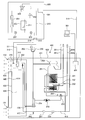
- FIG. 1 is a refrigerant circuit diagram showing a schematic configuration of a refrigeration cycle apparatus according to the present embodiment.
- a separate type air conditioner is illustrated as the refrigeration cycle apparatus.
- the dimensional relationship and shape of each component may differ from the actual ones.
- the air conditioner has a refrigeration cycle 40 for circulating a refrigerant.
- the refrigeration cycle 40 includes a compressor 3, a refrigerant flow switching device 4, a heat source side heat exchanger 5 (for example, an outdoor heat exchanger), a decompression device 6, and a load side heat exchanger 7 (for example, an indoor heat exchanger).
- the air conditioner includes, for example, an indoor unit 1 (an example of a load unit) installed indoors, and an outdoor unit 2 (an example of a heat source unit) installed outdoor, for example.
- the indoor unit 1 and the outdoor unit 2 are connected via extension pipes 10a and 10b that are part of the refrigerant pipe.
- a slightly flammable refrigerant such as HFO-1234yf or HFO-1234ze, or a strong flammable refrigerant such as R290 or R1270 is used.
- These refrigerants may be used as a single refrigerant, or may be used as a mixed refrigerant in which two or more kinds are mixed.
- a refrigerant having a flammability at or above a slight combustion level (for example, 2 L or more in the ASHRAE 34 classification) may be referred to as a “flammable refrigerant”.
- non-flammable refrigerants such as R22 and R410A having nonflammability (for example, 1 in the ASHRAE 34 classification) can be used.
- these refrigerants have a density higher than that of air at atmospheric pressure (for example, the temperature is room temperature (25 ° C.)).
- the compressor 3 is a fluid machine that compresses sucked low-pressure refrigerant and discharges it as high-pressure refrigerant.
- the refrigerant flow switching device 4 switches the flow direction of the refrigerant in the refrigeration cycle 40 between the cooling operation and the heating operation.
- a four-way valve is used as the refrigerant flow switching device 4.
- the heat source side heat exchanger 5 is a heat exchanger that functions as a radiator (for example, a condenser) during cooling operation and functions as an evaporator during heating operation. In the heat source side heat exchanger 5, heat exchange is performed between the refrigerant flowing through the inside and air (outside air) blown by an outdoor fan 5f described later.
- the decompression device 6 decompresses the high-pressure refrigerant into a low-pressure refrigerant.
- an electronic expansion valve whose opening degree can be adjusted is used.
- the load-side heat exchanger 7 is a heat exchanger that functions as an evaporator during cooling operation and functions as a radiator (for example, a condenser) during heating operation. In the load-side heat exchanger 7, heat exchange is performed between the refrigerant circulating in the interior and air blown by an indoor blower fan 7f described later.
- the cooling operation is an operation for supplying a low-temperature and low-pressure refrigerant to the load-side heat exchanger 7
- the heating operation is an operation for supplying a high-temperature and high-pressure refrigerant to the load-side heat exchanger 7. It is.
- a compressor 3, a refrigerant flow switching device 4, a heat source side heat exchanger 5 and a pressure reducing device 6 are accommodated.
- the outdoor unit 2 accommodates an outdoor blower fan 5 f that supplies outside air to the heat source side heat exchanger 5.
- the outdoor fan 5f is installed to face the heat source side heat exchanger 5. By rotating the outdoor fan 5f, an air flow passing through the heat source side heat exchanger 5 is generated.
- a propeller fan is used as the outdoor blower fan 5f.
- the outdoor fan 5f is arranged, for example, on the downstream side of the heat source side heat exchanger 5 in the air flow generated by the outdoor fan 5f.
- a refrigerant pipe connecting the extension pipe connection valve 13 a on the gas side (during cooling operation) and the refrigerant flow switching device 4, and a suction pipe 11 connected to the suction side of the compressor 3.
- a discharge pipe 12 connected to the discharge side of the compressor 3, a refrigerant pipe connecting the refrigerant flow switching device 4 and the heat source side heat exchanger 5, and a refrigerant pipe connecting the heat source side heat exchanger 5 and the decompression device 6.
- coolant piping which connects the decompression device 6 and the extension piping connection valve
- the extension pipe connection valve 13a is a two-way valve that can be switched between open and closed, and a flare joint is attached to one end thereof.
- the extension pipe connection valve 13b is composed of a three-way valve that can be switched between open and closed, and is a service that is used when evacuating one end of the valve (before the refrigerant is charged into the refrigeration cycle 40).
- a mouth 14a is attached, and a flare joint is attached to the other end.
- the high-temperature and high-pressure gas refrigerant compressed by the compressor 3 flows through the discharge pipe 12 during both the cooling operation and the heating operation.
- a low-temperature and low-pressure refrigerant gas refrigerant or two-phase refrigerant that has undergone an evaporating action flows through the suction pipe 11 in both the cooling operation and the heating operation.
- a service port 14b with a low-pressure side flare joint is connected to the suction pipe 11, and a service port 14c with a flare joint on the high-pressure side is connected to the discharge pipe 12.
- the service ports 14b and 14c are used for measuring an operating pressure by connecting a pressure gauge at the time of installation or repair of the air conditioner.
- the indoor unit 1 accommodates a load side heat exchanger 7. Further, the indoor unit 1 is provided with an indoor fan 7f that supplies air to the load-side heat exchanger 7. By rotating the indoor blower fan 7f, an air flow passing through the load-side heat exchanger 7 is generated.
- a centrifugal fan for example, a sirocco fan, a turbo fan, etc.
- a cross flow fan for example, a diagonal fan
- an axial fan for example, a propeller fan
- the indoor blower fan 7f of this example is disposed on the upstream side of the load side heat exchanger 7 in the air flow generated by the indoor blower fan 7f, but is disposed on the downstream side of the load side heat exchanger 7. Also good.
- a joint portion 15a for example, a flare joint for connecting the extension piping 10a is provided at a connection portion with the extension piping 10a on the gas side.
- a joint part 15b for example, a flare joint for connecting the extension pipe 10b is provided in the connection part with the liquid side extension pipe 10b. It has been.
- the indoor unit 1 includes the intake air temperature sensor 91 that detects the temperature of the indoor air sucked from the room, and the refrigerant temperature at the inlet portion during the cooling operation of the load side heat exchanger 7 (the outlet portion during the heating operation).
- a heat exchanger inlet temperature sensor 92 to detect, a heat exchanger temperature sensor 93 to detect the refrigerant temperature (evaporation temperature or condensation temperature) of the two-phase part of the load side heat exchanger 7 are provided.
- the indoor unit 1 is provided with a refrigerant detection means 99 described later. These sensors output a detection signal to the control unit 30 that controls the indoor unit 1 or the entire air conditioner.
- the control unit 30 has a microcomputer (hereinafter sometimes referred to as “microcomputer”) having a CPU, a ROM, a RAM, an I / O port, and the like.
- the control unit 30 can perform data communication with the operation unit 26 described later.
- the control unit 30 of this example controls the operation of the indoor unit 1 or the entire air conditioner including the operation of the indoor blower fan 7f based on the operation signal from the operation unit 26, the detection signal from the sensors, and the like.
- the control unit 30 may be provided in the housing of the indoor unit 1 or may be provided in the housing of the outdoor unit 2.
- the control part 30 may be comprised by the outdoor unit control part provided in the outdoor unit 2, and the indoor unit control part provided in the indoor unit 1 and capable of data communication with the outdoor unit control part.
- a solid line arrow indicates the flow direction of the refrigerant during the cooling operation.
- the refrigerant flow path switching device 4 switches the refrigerant flow path as indicated by a solid line, and the refrigerant circuit is configured so that the low-temperature and low-pressure refrigerant flows through the load-side heat exchanger 7.
- the high-temperature and high-pressure gas refrigerant discharged from the compressor 3 first flows into the heat source side heat exchanger 5 through the refrigerant flow switching device 4.
- the heat source side heat exchanger 5 functions as a condenser. That is, in the heat source side heat exchanger 5, heat exchange is performed between the refrigerant circulating inside and the air (outside air) blown by the outdoor blower fan 5f, and the heat of condensation of the refrigerant is radiated to the blown air. Thereby, the refrigerant flowing into the heat source side heat exchanger 5 is condensed and becomes a high-pressure liquid refrigerant.
- the high-pressure liquid refrigerant flows into the decompression device 6 and is decompressed to become a low-pressure two-phase refrigerant.
- the low-pressure two-phase refrigerant flows into the load side heat exchanger 7 of the indoor unit 1 via the extension pipe 10b.
- the load side heat exchanger 7 functions as an evaporator. That is, in the load-side heat exchanger 7, heat exchange is performed between the refrigerant circulating in the interior and the air (indoor air) blown by the indoor blower fan 7f, and the evaporation heat of the refrigerant is absorbed from the blown air.
- the refrigerant flowing into the load-side heat exchanger 7 evaporates to become a low-pressure gas refrigerant or a two-phase refrigerant. Further, the air blown by the indoor blower fan 7f is cooled by the endothermic action of the refrigerant.
- the low-pressure gas refrigerant or two-phase refrigerant evaporated in the load side heat exchanger 7 is sucked into the compressor 3 via the extension pipe 10 a and the refrigerant flow switching device 4.
- the refrigerant sucked into the compressor 3 is compressed into a high-temperature and high-pressure gas refrigerant. In the cooling operation, the above cycle is repeated.
- the refrigerant flow path switching device 4 switches the refrigerant flow path as indicated by the dotted line, and the refrigerant circuit is configured so that the high-temperature and high-pressure refrigerant flows through the load-side heat exchanger 7.
- the refrigerant flows in the opposite direction to that during the cooling operation, and the load side heat exchanger 7 functions as a condenser.
- FIG. 2 is a front view showing an external configuration of the indoor unit 1 of the air-conditioning apparatus according to the present embodiment.
- FIG. 3 is a front view schematically showing the internal structure of the indoor unit 1 (with the front panel removed).
- FIG. 4 is a side view schematically showing the internal structure of the indoor unit 1. The left side in FIG. 4 shows the front side (indoor space side) of the indoor unit 1.
- the indoor unit 1 a floor-standing indoor unit 1 installed on the floor surface of the indoor space serving as the air-conditioning target space is illustrated.
- the positional relationship for example, vertical relationship etc.
- the indoor unit 1 includes a casing 111 having a vertically long rectangular parallelepiped shape.
- a suction port 112 for sucking air in the indoor space is formed in the lower front portion of the housing 111.
- the suction port 112 of this example is provided below the center portion in the vertical direction of the casing 111 and at a position near the floor surface.
- the air sucked from the suction port 112 is blown out into the room.
- An outlet 113 is formed.
- An operation unit 26 is provided on the front surface of the casing 111 above the suction port 112 and below the air outlet 113.
- the operation unit 26 is connected to the control unit 30 via a communication line, and data communication with the control unit 30 is possible.
- the operation start operation, the operation end operation, the operation mode switching, the set temperature, the set air volume, and the like of the indoor unit 1 (air conditioner) are performed by a user operation.
- the operation unit 26 may be provided with a display unit, an audio output unit, and the like that notify the user of information.
- the housing 111 is a hollow box, and a front opening is formed on the front surface of the housing 111.
- the casing 111 includes a first front panel 114a, a second front panel 114b, and a third front panel 114c that are detachably attached to the front opening.
- the first front panel 114a, the second front panel 114b, and the third front panel 114c all have a substantially rectangular flat plate-like outer shape.
- the first front panel 114a is detachably attached to the lower portion of the front opening of the casing 111.
- the suction port 112 is formed in the first front panel 114a.
- the second front panel 114b is disposed adjacent to and above the first front panel 114a, and is detachably attached to the central portion of the front opening of the housing 111 in the vertical direction.
- the operation unit 26 is provided on the second front panel 114b.
- the third front panel 114c is disposed adjacent to and above the second front panel 114b, and is detachably attached to the upper portion of the front opening of the housing 111.
- the above-described air outlet 113 is formed in the third front panel 114c.
- the internal space of the housing 111 is roughly divided into a space 115a serving as a blower section and a space 115b positioned above the space 115a and serving as a heat exchange section.
- the space 115a and the space 115b are partitioned by the partition portion 20.
- the partition part 20 has a flat plate shape, for example, and is arranged substantially horizontally.
- the partition portion 20 is formed with at least an air passage opening 20a serving as an air passage between the space 115a and the space 115b.
- the space 115a is exposed to the front side by removing the first front panel 114a from the housing 111, and the space 115b is obtained by removing the second front panel 114b and the third front panel 114c from the housing 111. Is exposed on the front side.
- the height at which the partition portion 20 is installed substantially matches the height of the upper end of the first front panel 114a (or the lower end of the second front panel 114b).
- the partition portion 20 may be formed integrally with a fan casing 108 described later, or may be formed integrally with a drain pan described later, or as a separate body from the fan casing 108 and the drain pan. It may be formed.
- an indoor blower fan 7f that generates an air flow from the inlet 112 toward the outlet 113 is disposed.
- the indoor blower fan 7f of this example is a sirocco fan that includes a motor (not shown) and an impeller 107 that is connected to an output shaft of the motor and has a plurality of blades arranged at equal intervals in the circumferential direction.
- the rotating shaft of the impeller 107 (motor output shaft) is arranged so as to be substantially parallel to the depth direction of the casing 111.
- the impeller 107 of the indoor blower fan 7 f is covered with a spiral fan casing 108.
- the fan casing 108 is formed separately from the casing 111, for example.
- a suction opening 108b for sucking room air through the suction port 112 is formed.
- the suction opening 108 b is disposed so as to face the suction port 112.
- a blowout opening 108a for blowing out the blown air is formed.
- the blowout opening 108 a is disposed so as to face upward, and is connected to the space 115 b through the air passage opening 20 a of the partition part 20.
- the outlet opening 108a communicates with the space 115b via the air passage opening 20a.
- the opening end of the outlet opening 108a and the opening end of the air passage opening 20a may be directly connected or indirectly connected via a duct member or the like.
- an electrical component box 25 in which a microcomputer constituting the control unit 30 and the like, various electrical components, a substrate and the like are accommodated is provided.
- the load side heat exchanger 7 is arranged in the air passage 81 in the space 115b.
- a drain pan (not shown) that receives condensed water condensed on the surface of the load side heat exchanger 7 is provided below the load side heat exchanger 7.
- the drain pan may be formed as a part of the partition part 20, or may be formed separately from the partition part 20 and disposed on the partition part 20.
- a refrigerant detection means 99 is provided at a position near the lower side in the vicinity of the suction opening 108b.
- the refrigerant detection means 99 for example, a gas sensor such as a semiconductor gas sensor or a hot wire semiconductor gas sensor is used.
- the refrigerant detection unit 99 detects, for example, the refrigerant concentration in the air around the refrigerant detection unit 99 and outputs a detection signal to the control unit 30. In the control unit 30, the presence or absence of refrigerant leakage is determined based on the detection signal from the refrigerant detection means 99.
- the refrigerant detection means 99 of the present embodiment is provided in a position lower in the casing 111 than the load-side heat exchanger 7 and the joint portions 15a and 15b. Thereby, at least when the indoor blower fan 7f is stopped, the refrigerant detection means 99 can reliably detect the leaked refrigerant.
- the refrigerant detection means 99 is provided at a position closer to the lower side of the suction opening 108b, but the installation position of the refrigerant detection means 99 may be another position.
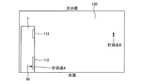
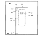
- FIG. 5 is a diagram illustrating an example of a state where the indoor unit 1 is installed in the indoor space 120.
- the refrigerant is intentionally leaked from the indoor unit 1 in the stopped state, and the measurement point A inside the indoor unit 1 and in the vicinity of the installation position of the refrigerant detection means 99 and the indoor unit 1
- the refrigerant concentration was measured at a measurement point B that is also away from the floor.
- FIG. 6 is a graph showing an example of a change over time in the refrigerant concentration when the refrigerant is leaked from the indoor unit 1.
- the horizontal axis of the graph represents time, and the vertical axis represents the refrigerant concentration.
- the solid line shows the change over time in the refrigerant concentration at the measurement point A, and the broken line shows the change over time in the refrigerant concentration at the measurement point B.
- FIG. 6 when refrigerant leakage starts in the indoor unit 1 at time T ⁇ b> 0, first, the refrigerant concentration at the measurement point A inside the indoor unit 1 increases.
- the refrigerant concentration at the measurement point A (more precisely, the refrigerant concentration detected by the refrigerant detection means 99) reaches a preset threshold value (time T1 in FIG. 6), as will be described later, The operation of the blower fan 7f is started. As a result, the air in the indoor space 120 is agitated and the refrigerant diffuses, so that the refrigerant concentration at the measurement point A temporarily decreases (time T1 to T2). However, since the leakage of the refrigerant in the indoor unit 1 continues, the refrigerant concentration at the measurement point A starts to increase again after time T2.
- the refrigerant concentration at the measurement point B which is away from the indoor unit 1 and the floor surface, hardly changes immediately after the start of refrigerant leakage.
- the refrigerant concentration at the measurement point B rapidly increases when the operation of the indoor blower fan 7f is started (time T1 to T2), and after a certain time has elapsed from the start of operation of the indoor blower fan 7f, the refrigerant at the measurement point A It almost coincides with the concentration (time T2). That is, the refrigerant leaked from the indoor unit 1 is uniformly diffused throughout the indoor space 120 due to the stirring effect by the operation of the indoor blower fan 7f.
- the refrigerant concentration after time T2 increases while maintaining a substantially uniform state in the entire indoor space 120.
- the refrigerant leakage ends (time T3).
- the increase in the refrigerant concentration stops.
- the refrigerant in the indoor space 120 leaks out of the room due to natural ventilation through the upper and lower gaps of the door.
- the refrigerant concentration in the entire indoor space 120 gradually decreases regardless of the operation and stop of the indoor blower fan 7f (after time T3). That is, after the refrigerant leakage is finished, the refrigerant concentration can be gradually lowered even if the indoor blower fan 7f is stopped. Therefore, in the present embodiment, the indoor blower fan 7f is stopped when the refrigerant leakage ends. Thereby, it is possible to prevent unnecessary energy from being consumed.
- the time change from positive to negative includes not only the case where the time change directly changes from positive to negative, but also the case where the time change changes from positive to negative through zero.
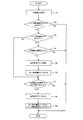
- FIG. 7 is a flowchart showing an example of the flow of the refrigerant leakage detection process (the operation and stop process of the indoor fan 7f) executed by the control unit 30.
- the refrigerant leakage detection process of FIG. 7 is repeatedly executed at predetermined time intervals at all times including during operation and stop of the air conditioner or only when the air conditioner is stopped.
- FIG. 8 is a state transition diagram illustrating an example of state transition of the air conditioner.
- the air conditioner in the initial state is in a normal state (no leakage state in FIG. 8) in which no refrigerant leaks.
- two flag areas of “fan forced operation flag” and “fan forced operation stop flag” are set in the RAM of the control unit 30. In the initial state, both the fan forced operation flag and the fan forced operation stop flag are set to off.
- a normal driving operation and a stopping operation are performed based on a user operation by the operation unit 26 (including a remote controller).
- control unit 30 acquires information on the refrigerant concentration around the refrigerant detection means 99 based on the detection signal from the refrigerant detection means 99.
- step S2 it is determined whether or not the fan forced operation stop flag in the RAM is set to OFF.
- the process proceeds to step S3, and when the fan forced operation stop flag is set to ON, the process ends.
- step S3 it is determined whether or not the fan forced operation flag in the RAM is set to OFF. If the fan forced operation flag is set to OFF, the process proceeds to step S4. If the fan forced operation flag is set to ON, the process proceeds to step S7.
- step S4 it is determined whether or not the refrigerant concentration detected by the refrigerant detection means 99 is equal to or greater than a preset threshold value. If it is determined that the refrigerant concentration is greater than or equal to the threshold value, the process proceeds to step S5, and if it is determined that the refrigerant concentration is less than the threshold value, the process ends.
- step S5 the operation of the indoor fan 7f is started (corresponding to time T1 in FIG. 6). When the indoor fan 7f is already in operation, the operation is continued as it is.
- the display unit liquid crystal screen or LED or the like
- a sound output unit, or the like is used to notify the user that the refrigerant has leaked and repaired by a professional service person. You may make it prompt.
- step S6 the fan forced operation flag is set to ON.
- the state of the air conditioner is set to the first abnormal state (leak state 1 in FIG. 8 (refrigerant leaking)). Then, it progresses to step S7.
- step S7 it is determined whether or not the change in the refrigerant concentration with time detected by the refrigerant detector 99 has changed from positive to negative.
- the process proceeds to step S8, and in other cases, the process ends.
- the refrigerant concentration detected by the refrigerant detection means 99 may temporarily decrease immediately after the activation of the indoor fan 7f (time T1 to T2), the indoor fan 7f Until a predetermined time elapses from the activation of, the process may be terminated without performing the determination in step S7.
- step S8 the indoor blower fan 7f is stopped (corresponding to time T3 in FIG. 6).
- the refrigerant concentration in the indoor space 120 is an allowable value (for example, the lower combustion limit concentration LFL or oxygen deficiency).
- an allowable value for example, the lower combustion limit concentration LFL or oxygen deficiency.
- a step of determining whether or not the refrigerant concentration is less than the allowable value may be further added after the Yes determination in step S7.
- step S8 the process proceeds to step S8 to stop the indoor blower fan 7f, and if it is determined that the refrigerant concentration is equal to or higher than the allowable value, processing is performed. Exit. Thereby, since the driving
- step S9 the fan forced operation flag is set to OFF and the fan forced operation stop flag is set to ON.
- the state of the air conditioner is set to the second abnormal state (leak state 2 (refrigerant leakage stop) in FIG. 8).
- the indoor fan 7f is operated. Be started. For this reason, the leaked refrigerant can be diffused indoors. Further, the operation of the indoor blower fan 7f is continued until the refrigerant leakage ends. Therefore, even if the refrigerant leaks, it can be suppressed that the refrigerant concentration is locally increased indoors.
- the indoor blower fan 7f can be stopped when the refrigerant leakage ends. Therefore, it is possible to prevent unnecessary energy from being consumed. Moreover, it is possible to prevent the user from having unnecessary uneasiness by continuing to operate the indoor fan 7f. After the refrigerant leakage ends, the indoor refrigerant concentration usually decreases gradually and does not increase again. For this reason, it can also be suppressed that the refrigerant concentration increases locally in the room after the indoor blower fan 7f is stopped.
- both the fan forced operation flag and the fan forced operation stop flag are set to OFF. Absent. Therefore, as shown in FIG. 8, once the state of the air conditioner is set to the leaked state 1 or the leaked state 2, the service person repairs the air conditioner, and then the service person clears the abnormality. Unless the fan forced operation stop flag is set to OFF, it does not return to the state without leakage.
- the method for canceling the abnormality is limited to a method that can be performed only by a professional service person. Thereby, since it can prevent that a user cancels
- the method for canceling the abnormality is limited to the following (1) to (4), for example.
- the refrigeration cycle apparatus includes the refrigeration cycle 40 that circulates the refrigerant, and the indoor unit 1 that houses at least the load-side heat exchanger 7 of the refrigeration cycle 40 and is installed indoors.
- the refrigeration cycle apparatus having the control unit 30 that controls the indoor unit 1, wherein the indoor unit 1 detects the indoor blower fan 7 f and the concentration of the leaked refrigerant and outputs a detection signal to the control unit 30.
- the refrigerant detecting means 99 is provided, and the control unit 30 operates the indoor blower fan 7f when detecting the leakage of the refrigerant, and triggers that the time change of the concentration of the leaked refrigerant has changed from positive to negative.
- the indoor fan 7f is configured to be stopped.
- the indoor ventilation fan 7f can be stopped when the refrigerant
- FIG. 9 is a flowchart illustrating an example of the flow of the refrigerant leakage detection process executed by the control unit 30 of the air conditioner.
- the refrigerant leakage detection process of FIG. 9 is repeatedly executed at predetermined time intervals at all times including during operation and stop of the air conditioner or only when the air conditioner is stopped. Steps S11 to S16, S18 and S19 in FIG. 9 are the same as steps S1 to S6, S8 and S9 in FIG. 7, respectively.
- step S17 of FIG. 9 it is determined whether or not the change in the refrigerant concentration with time detected by the refrigerant detector 99 is negative (that is, whether or not the refrigerant concentration is decreasing).
- the process proceeds to step S18, and in other cases, the process ends. Note that, similarly to step S7 in FIG. 7, the process may be terminated without performing the determination in step S17 until a predetermined time has elapsed since the activation of the indoor fan 7f.
- the refrigeration cycle apparatus includes the refrigeration cycle 40 that circulates the refrigerant, and the indoor unit 1 that houses at least the load-side heat exchanger 7 of the refrigeration cycle 40 and is installed indoors.
- the refrigeration cycle apparatus having the control unit 30 that controls the indoor unit 1, wherein the indoor unit 1 detects the indoor blower fan 7 f and the concentration of the leaked refrigerant and outputs a detection signal to the control unit 30.
- Refrigerant control means 99, and the control unit 30 operates the indoor blower fan 7f when detecting leakage of the refrigerant, and the indoor blower fan 7f when the time change of the concentration of the leaked refrigerant is negative. Is configured to stop.
- the indoor ventilation fan 7f can be stopped when the refrigerant
- FIG. 10 is a graph showing an example of the change over time in the refrigerant concentration when the refrigerant is leaked from the indoor unit 1, and corresponds to FIG.
- the horizontal axis of the graph represents time, and the vertical axis represents the refrigerant concentration.
- the solid line shows the change over time in the refrigerant concentration at the measurement point A, and the broken line shows the change over time in the refrigerant concentration at the measurement point B.
- the forced operation of the indoor fan 7f is started, and the display unit, the audio output unit, and the like are notified to the user that the refrigerant leakage has occurred. If the forced operation of the indoor blower fan 7f or the notification of refrigerant leakage is suddenly executed, a user who is indoors may be surprised and go out of the room.
- the change in the refrigerant concentration over time is not only the timing at which the refrigerant leakage ends (time T5), but also the timing at which the operation of the indoor fan 7f is started (time T1), and the door opens during the refrigerant leakage. Also at the given timing (time T3), it changes from positive to negative.
- the time change of the refrigerant concentration becomes negative not only in the period after time T5 when the refrigerant leakage ends, but also in the period from time T1 to T2 and the period from time T3 to T4. Therefore, when the indoor blower fan 7f is stopped when the change in the refrigerant concentration with time is negative (for example, the second embodiment), the indoor blower fan 7f may be stopped before the refrigerant leakage ends. .
- the stopped indoor ventilation fan 7f when the time change of a refrigerant
- the time change changes from negative to positive includes not only the case where the time change directly changes from negative to positive but also the case where the time change changes positive from negative to zero.
- concentration is positive, you may make it operate the stopped indoor ventilation fan 7f again.
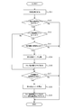
- FIG. 11 is a flowchart showing an example of the flow of the refrigerant leakage detection process executed by the control unit 30.
- the refrigerant leakage detection process in FIG. 11 is repeatedly executed at predetermined time intervals at all times including during operation and stop of the air conditioner or only when the air conditioner is stopped.
- Steps S21 to S25 and S27 to S29 in FIG. 11 are the same as steps S1 to S5 and S7 to S9 in FIG. 7, respectively.
- FIG. 12 is a state transition diagram illustrating an example of state transition of the air conditioner.
- step S30 in FIG. 11 in a state where the fan forced operation stop flag is set to ON (No in step S22 in FIG. 11; leakage state 2 in FIG. 12), has the refrigerant concentration changed over time from negative to positive? It is determined whether or not (step S30 in FIG. 11). If it is determined in step S30 that the change in the refrigerant concentration with time has changed from negative to positive, the process proceeds to step S25, and the operation of the stopped indoor fan 7f is resumed. Thereafter, in step S26, the fan forced operation stop flag is set to OFF, and the fan forced operation flag is set to ON. When the fan forced operation flag is set to ON, the state of the air conditioner transitions from the leakage state 2 in FIG. 12 to the leakage state 1. On the other hand, if it is determined in step S30 that the change in the refrigerant concentration with time remains negative or zero, the process ends.
- control unit 30 causes the stopped indoor fan 7f to be triggered by the change in the leaked refrigerant concentration over time from negative to positive. You may be comprised so that it may drive
- control unit 30 is configured to cause the stopped indoor blower fan 7f to operate again when the time change in the concentration of the leaked refrigerant is positive. Also good.
- the stopped indoor blower fan 7f can be operated again.
- Embodiment 4 FIG. Next, a refrigeration cycle apparatus according to Embodiment 4 of the present invention will be described. Note that the configuration of the refrigeration cycle apparatus according to the present embodiment is the same as that of the first embodiment, and a description thereof will be omitted.
- the indoor blower fan 7f when the indoor blower fan 7f is stopped when the change in the refrigerant concentration with time changes from positive to negative (for example, Embodiment 1), or when the change in the refrigerant concentration with time is negative.
- the indoor blower fan 7f is stopped (for example, Embodiment 2), the indoor blower fan 7f may be stopped before the refrigerant leakage ends.
- the threshold time is set to a time (several seconds to several minutes) longer than the period of time T3 to T4 in FIG.
- FIG. 13 is a flowchart showing an example of the flow of the refrigerant leakage detection process executed by the control unit 30.
- the refrigerant leakage detection process of FIG. 13 is repeatedly executed at predetermined time intervals at all times including during operation and stop of the air conditioner or only when the air conditioner is stopped.
- Steps S31 to S37, S39 and S40 in FIG. 13 are the same as steps S1 to S9 in FIG.
- FIG. 14 is a state transition diagram illustrating an example of state transition of the air conditioner.
- step S38 when the fan forced operation flag is set to ON (step S37 in FIG. 13; leakage state 1 in FIG. 14), the change in the refrigerant concentration with time changes from positive to negative (step Further, it is determined whether or not the decrease in the refrigerant concentration has continued for a threshold time or more (step S38). If it is determined in step S38 that the decrease in the refrigerant concentration has continued for the threshold time or longer, the process proceeds to step S39, and the indoor blower fan 7f is stopped. Thereafter, in step S40, the fan forced operation flag is set to OFF, and the fan forced operation stop flag is set to ON. By setting the fan forced operation stop flag to ON, the state of the air conditioner is set to the leakage present state 2 in FIG. On the other hand, when it is determined in step S38 that the refrigerant concentration decrease time has not been continued for the threshold time or longer, the process is terminated.
- control unit 30 causes the indoor state when the state in which the time change in the concentration of the leaked refrigerant is negative continues for a preset threshold time or longer.
- the blower fan 7f is configured to be stopped.
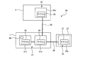
- FIG. 15 is a block diagram illustrating a configuration of the control unit 30 of the separate type air conditioner.
- the control unit 30 includes an indoor unit control unit 31 that is mounted on the indoor unit 1 and controls the indoor unit 1, and an outdoor unit control unit 32 that is mounted on the outdoor unit 2 and controls the outdoor unit 2. And a remote controller control unit 33 that is mounted on the remote controller 27 (or the operation unit 26) and controls the remote controller 27.
- the indoor unit control unit 31 includes a control board 31a and a control board 31b that can communicate with the control board 31a via a control line.
- the indoor unit control unit 31 can communicate with the outdoor unit control unit 32 and the remote control unit 33.
- a microcomputer 34 is mounted on the control board 31a.
- the control board 31b is mounted with a microcomputer 35 and a refrigerant detection means 99 (for example, a hot-wire semiconductor gas sensor) in a non-detachable manner.
- a refrigerant detection means 99 for example, a hot-wire semiconductor gas sensor
- the refrigerant detection means 99 may be provided at a position away from the control board 31b, and the wiring from the refrigerant detection means 99 may be connected to the control board 31b by soldering or the like.
- the control board 31b is provided separately from the control board 31a.
- the control board 31b may be omitted, and the refrigerant detection means 99 may be detachably connected to the control board 31a.
- the outdoor unit controller 32 has a control board 32a.
- a microcomputer 36 is mounted on the control board 32a.
- the remote controller 33 has a control board 33a.
- a microcomputer 37 is mounted on the control board 33a.
- the indoor unit control unit 31 and the outdoor unit control unit 32 are communicably connected via a control line 38.
- the indoor unit control unit 31 and the remote control unit 33 are communicably connected via a control line 39.
- the microcomputer 35 mounted on the control board 31b has a rewritable nonvolatile memory (for example, a flash memory).
- This nonvolatile memory is provided with a leakage history bit for storing a history of refrigerant leakage.
- the leakage history bit of the microcomputer 35 can be set to “0” or “1”.
- the initial value of this leakage history bit is “0”. In other words, in the case of the microcomputer 35 in a new state or the microcomputer 35 without a refrigerant leakage history, the leakage history bit is set to “0”.
- the leakage history bit of the microcomputer 35 is detected when the refrigerant detection means 99 detects the leakage of the refrigerant having a predetermined concentration (for example, a concentration of 1 ⁇ 4 of the lower combustion limit concentration LFL, a threshold value at which the indoor blower fan 7f starts operating). , “0” is rewritten to “1”. The leakage history bit of the microcomputer 35 can be irreversibly rewritten only in one direction from “0” to “1”. Further, the leakage history bit of the microcomputer 35 is maintained regardless of whether power is supplied to the microcomputer 35.
- the leakage history bit of the present embodiment is provided corresponding to the fan forced operation flag or the fan forced operation stop flag of the first to fourth embodiments.
- the memory (nonvolatile memory or volatile memory) of the microcomputers 34, 36, and 37 is provided with a leakage history bit corresponding to the leakage history bit of the microcomputer 35, respectively.
- the leakage history bits of the microcomputers 34, 36, and 37 can be set to “0” or “1”.
- the leakage history bits of the microcomputers 34, 36, and 37 can be rewritten bidirectionally between “0” and “1”.
- the value of the leakage history bit of the microcomputers 34, 36, and 37 is set to the same value as the leakage history bit of the microcomputer 35 acquired by communication.
- the leakage history bits of the microcomputers 34, 36, and 37 are set to the same value as the leakage history bits of the microcomputer 35 again when the power supply is resumed even if the power supply is interrupted and returns to the initial value (for example, “0”). Is set.
- the indoor unit control unit 31 When the leakage history bit of the microcomputer 34 is set to “0”, the indoor unit control unit 31 performs normal control of the indoor unit 1. The indoor unit 1 in this state performs a normal driving operation and a stopping operation based on the operation of the remote controller 27 or the like. On the other hand, when the leakage history bit of the microcomputer 34 is set to “1”, the indoor unit control unit 31 performs control to forcibly operate the indoor blower fan 7f.
- the outdoor unit control unit 32 When the leakage history bit of the microcomputer 36 is set to “0”, the outdoor unit control unit 32 performs normal control of the outdoor unit 2. On the other hand, when the leakage history bit of the microcomputer 36 is set to “1”, the outdoor unit control unit 32 performs control to stop the compressor 3. The stop of the compressor 3 is continued as long as the leakage history bit of the microcomputer 36 is continuously set to “1”.
- the remote controller control unit 33 When the leakage history bit of the microcomputer 37 is set to “0”, the remote controller control unit 33 performs normal control of the remote controller 27. On the other hand, when the leakage history bit of the microcomputer 37 is set to “1”, the remote controller control unit 33 displays, for example, information including an abnormality type or a treatment method on the display unit provided in the remote controller 27 (for example, “refrigerant leakage” Display a message such as “Contact Serviceman”, error code, etc.). This display is continued as long as the leakage history bit of the microcomputer 37 continues to be set to “1”.
- the microcomputer 35 irreversibly rewrites the leakage history bit from the initial value “0” to “1”.
- the leakage history bit of the microcomputer 35 is set to “1”
- the leakage history bits of the microcomputers 34, 36, and 37 are also rewritten from “0” to “1”.
- the service person who received the notification from the user replaces the control board 31b with a new one when repairing the refrigerant leakage point. This is because the leakage history bit of the microcomputers 34, 36, and 37 is maintained at “1” only by repairing the refrigerant leakage portion, and thus the normal operation of the air conditioner cannot be performed. Since the refrigerant detection means 99 is detachably connected to the control board 31b, the refrigerant detection means 99 is also exchanged when the control board 31b is exchanged.
- the leakage history bit of the microcomputer 35 mounted on the replaced control board 31b is set to “0” which is an initial value. Therefore, the leakage history bits of the microcomputers 34, 36, and 37 are also rewritten from “1” to “0”. Thereby, normal operation
- the refrigeration cycle apparatus includes the refrigeration cycle 40 that circulates the refrigerant, and the indoor unit 1 that houses at least the load-side heat exchanger 7 of the refrigeration cycle 40 and is installed indoors.
- the outdoor unit 2 that houses at least the heat source side heat exchanger 5 of the refrigeration cycle 40, the indoor unit control unit 31 that controls the indoor unit 1, and the indoor unit control unit 31 are communicably connected to control the outdoor unit 2.
- the indoor unit 1 includes an indoor blower fan 7f and a refrigerant detection means 99 that detects the refrigerant
- the indoor unit control unit 31 includes: A control board (in this example, the control board 31b) to which the refrigerant detection means 99 is detachably connected, and a non-volatile memory (in this example, a non-volatile memory provided in the microcomputer 35) provided in the control board; , Have The non-volatile memory is provided with leak history bits that can be set to initial values “0” and “1”. The leak history bits are changed from “0” to “1”.
- the indoor unit control unit 31 can be rewritten only in one direction, and is configured to rewrite the leakage history bit from “0” to “1” and to operate the indoor blower fan 7f when refrigerant leakage is detected. It is what has been. Further, the outdoor unit control unit 32 may be configured to stop the compressor 3 when the leakage history bit is rewritten from “0” to “1”.
- the refrigerant leakage history is irreversibly written in the nonvolatile memory of the control board 31b.
- the control board 31b In order to reset the leakage history of the refrigerant, it is necessary to replace the control board 31b with another control board 31b having no leakage history.
- the refrigerant detection means 99 that is detachably connected is also replaced. Therefore, it is possible to prevent the refrigerant detecting means 99 that has been exposed to the refrigerant atmosphere and whose detection characteristics have changed from being used continuously. Further, in this configuration, since the operation of the air conditioner cannot be resumed unless the control board 31b is replaced, the operation of the air conditioner that has not been repaired at the refrigerant leakage point is resumed due to human error or intentionally. Can be prevented.
- FIG. 6 A refrigeration cycle apparatus according to Embodiment 6 of the present invention will be described with reference to FIG.
- the refrigerant detection means 99 A failure bit for storing a failure history (for example, whether there is a failure) is provided.
- the failure bit can be set to “0” or “1” similarly to the leakage history bit, and its initial value is “0”. That is, in the case of the microcomputer 35 in a new state or the microcomputer 35 having no failure history of the refrigerant detection means 99, the failure bit is set to “0”.
- the failure bit of the microcomputer 35 is rewritten from “0” to “1”.
- the failure bit of the microcomputer 35 can be irreversibly rewritten only in one direction from “0” to “1”, similarly to the leakage history bit.
- the failure bit of the microcomputer 35 is maintained regardless of whether or not power is supplied to the microcomputer 35.
- the memory (nonvolatile memory or volatile memory) of the microcomputers 34, 36, and 37 is provided with a failure bit corresponding to the failure bit of the microcomputer 35, respectively.
- the failure bits of the microcomputers 34, 36, and 37 can be set to “0” or “1”.
- the failure bits of the microcomputers 34, 36, and 37 can be rewritten bidirectionally between “0” and “1”.
- the value of the failure bit of the microcomputers 34, 36, and 37 is set to the same value as the failure bit of the microcomputer 35 acquired by communication.
- the failure bits of the microcomputers 34, 36, and 37 are set to the same values as the failure bits of the microcomputer 35 again when the power supply is resumed even if the power supply is cut off and returned to the initial value (eg, “0”).
- the indoor unit control unit 31, the outdoor unit control unit 32, and the remote control unit 33 are the indoor unit 1, the outdoor unit 2, and the remote control 27, respectively. Perform normal control.
- the outdoor unit control unit 32 and the remote control unit 33 perform forced stop of the compressor 3 (operation not permitted) and information to the display unit of the remote control 27, respectively. Control display.
- the indoor unit control unit 31 may control the forced operation of the indoor fan 7f.
- the refrigeration cycle apparatus includes the refrigeration cycle 40 that circulates the refrigerant, and the indoor unit 1 that houses at least the load-side heat exchanger 7 of the refrigeration cycle 40 and is installed indoors.
- a refrigeration cycle apparatus having a control unit 30 (for example, an indoor unit control unit 31) that controls the indoor unit 1, wherein the indoor unit 1 includes an indoor blower fan 7f and a refrigerant detection means 99 that detects the refrigerant.
- the control unit 30 includes a control board (in this example, the control board 31b) to which the refrigerant detection means 99 is detachably connected, and a non-volatile memory (in this example, provided in the control board).
- the failure history of the refrigerant detection means 99 is irreversibly written in the nonvolatile memory of the control board 31b.
- the control board 31b In order to reset the failure history of the refrigerant detection means 99, it is necessary to replace the control board 31b with another control board 31b.
- the refrigerant detection means 99 that is detachably connected is also replaced. Therefore, it is possible to prevent the failed refrigerant detection means 99 from being used continuously.
- the operation of the air conditioner cannot be resumed unless the control board 31b is replaced, the operation of the air conditioner in a state where the refrigerant detection means 99 remains broken will be resumed due to human error or intentionally. Can be prevented. For this reason, the safety
- Embodiment 7 FIG. Next, a refrigeration cycle apparatus according to Embodiment 7 of the present invention will be described.
- a heat pump water heater is illustrated as the refrigeration cycle apparatus.
- the configuration of the refrigeration cycle apparatus according to the present embodiment will be described. Note that the flow of processing executed by the control unit in the present embodiment is the same as that in the first embodiment (or any one of the second to sixth embodiments), and a description thereof will be omitted.
- FIG. 16 is a refrigerant circuit diagram showing a schematic configuration of the refrigeration cycle apparatus according to the present embodiment.
- the heat pump water heater includes a refrigerant circuit 310 that circulates a refrigerant to form a refrigeration cycle, and a water circuit 410 (an example of a heat medium circuit) that distributes water (an example of a heat medium).
- the refrigerant circuit 310 includes a compressor 203, a refrigerant flow switching device 204, a load-side heat exchanger 202, a first decompression device 206, an intermediate pressure receiver 205, a second decompression device 207, and a heat source-side heat exchanger 201.
- the heat pump water heater has a load unit 400 (indoor unit) installed indoors, and a heat source unit 300 (outdoor unit) installed outdoor, for example.
- the load unit 400 is installed, for example, in a storage space such as a storage room inside a building in addition to a kitchen, a bathroom, and a laundry room.
- the above-described flammable refrigerant or non-flammable refrigerant is used as the refrigerant circulating in the refrigerant circuit 310.
- Compressor 203 is a fluid machine that compresses sucked low-pressure refrigerant and discharges it as high-pressure refrigerant.
- the compressor 203 of this example includes an inverter device and the like, and can change the capacity (the amount of refrigerant sent out per unit time) by arbitrarily changing the drive frequency.
- the refrigerant flow switching device 204 switches the flow direction of the refrigerant in the refrigerant circuit 310 between the normal operation and the defrosting operation.
- a four-way valve is used as the refrigerant flow switching device 204.
- the load-side heat exchanger 202 is a refrigerant-water heat exchanger that performs heat exchange between the refrigerant flowing through the refrigerant circuit 310 and the water flowing through the water circuit 410.
- a plate heat exchanger (brazing plate heat exchanger) having a configuration in which a plurality of members are joined by brazing is used.
- the load-side heat exchanger 202 functions as a condenser (heat radiator) that heats water during normal operation, and functions as an evaporator (heat absorber) during defrosting operation.
- the first decompression device 206 and the second decompression device 207 adjust the flow rate of the refrigerant and perform pressure adjustment (decompression) of the refrigerant flowing into the load side heat exchanger 202 or the heat source side heat exchanger 201.
- the intermediate pressure receiver 205 is located between the first decompression device 206 and the second decompression device 207 in the refrigerant circuit 310 and accumulates excess refrigerant.
- a suction pipe 211 connected to the suction side of the compressor 203 passes through the intermediate pressure receiver 205. In the intermediate pressure receiver 205, heat exchange between the refrigerant flowing through the suction pipe 211 and the refrigerant in the intermediate pressure receiver 205 is performed.
- the intermediate pressure receiver 205 has a function as an internal heat exchanger in the refrigerant circuit 310.
- the first pressure reducing device 206 and the second pressure reducing device 207 for example, electronic expansion valves that can change the opening degree under the control of the control unit 301 described later are used.
- the heat source side heat exchanger 201 is a refrigerant-air heat exchanger that performs heat exchange between the refrigerant flowing through the refrigerant circuit 310 and air (outside air) blown by an outdoor fan (not shown).
- the heat source side heat exchanger 201 functions as an evaporator (heat absorber) during normal operation, and functions as a condenser (heat radiator) during defrosting operation.
- the compressor 203, the refrigerant flow switching device 204, the first pressure reducing device 206, the intermediate pressure receiver 205, the second pressure reducing device 207, and the heat source side heat exchanger 201 are accommodated in the heat source unit 300.
- the load side heat exchanger 202 is accommodated in the load unit 400.
- the heat source unit 300 and the load unit 400 are connected by, for example, two extension pipes 311 and 312 that are part of the refrigerant pipe.
- the extension pipes 311 and 312 and the refrigerant pipe in the heat source unit 300 are connected via joint parts 313 and 314 (for example, flare joints), respectively.
- joint portions 315 and 316 are interposed. Are connected to each other.
- the heat source unit 300 is mainly operated by the refrigerant circuit 310 (for example, the compressor 203, the refrigerant flow switching device 204, the first decompression device 206, the second decompression device 207, an outdoor fan not shown).
- a control unit 301 for controlling is provided.
- the control unit 301 has a microcomputer provided with a CPU, ROM, RAM, I / O port, and the like.
- the control unit 301 can perform data communication with a control unit 401 and an operation unit 501 described later via a control line 510.
- the refrigerant circuit 310 Next, an example of the operation of the refrigerant circuit 310 will be described.
- the direction of refrigerant flow during normal operation in the refrigerant circuit 310 is indicated by solid arrows.
- the refrigerant flow switching device 204 switches the refrigerant flow path as indicated by a solid line, and the refrigerant circuit 310 is configured such that high-temperature and high-pressure refrigerant flows through the load-side heat exchanger 202.
- the load side heat exchanger 202 functions as a condenser. That is, in the load side heat exchanger 202, heat exchange between the refrigerant flowing through the refrigerant flow path and the water flowing through the water flow path of the load side heat exchanger 202 is performed, and the heat of condensation of the refrigerant is radiated to the water. Thereby, the refrigerant that has flowed into the load-side heat exchanger 202 condenses into a high-pressure liquid refrigerant. Moreover, the water which flows through the water flow path of the load side heat exchanger 202 is heated by the heat radiation from the refrigerant.
- the high-pressure liquid refrigerant condensed in the load-side heat exchanger 202 flows into the first decompression device 206 via the extension pipe 312 and is slightly decompressed to become a two-phase refrigerant.
- the two-phase refrigerant flows into the intermediate pressure receiver 205 and is cooled by heat exchange with the low-pressure gas refrigerant flowing through the suction pipe 211 to become a liquid refrigerant.
- This liquid refrigerant flows into the second decompression device 207 and is decompressed to become a low-pressure two-phase refrigerant.
- the low-pressure two-phase refrigerant flows into the heat source side heat exchanger 201. During normal operation, the heat source side heat exchanger 201 functions as an evaporator.
- the heat source side heat exchanger 201 heat exchange is performed between the refrigerant circulating in the interior and the air (outside air) blown by the outdoor blower fan, and the evaporation heat of the refrigerant is absorbed from the blown air.
- the refrigerant flowing into the heat source side heat exchanger 201 evaporates to become a low-pressure gas refrigerant.
- the low-pressure gas refrigerant flows into the suction pipe 211 via the refrigerant flow switching device 204.
- the low-pressure gas refrigerant that has flowed into the suction pipe 211 is heated by heat exchange with the refrigerant in the intermediate-pressure receiver 205 and is sucked into the compressor 203.
- the refrigerant sucked into the compressor 203 is compressed into a high-temperature and high-pressure gas refrigerant. In normal operation, the above cycle is repeated.
- the flow direction of the refrigerant during the defrosting operation in the refrigerant circuit 310 is indicated by a broken line arrow.
- the refrigerant flow path switching device 204 switches the refrigerant flow path as indicated by broken lines, and the refrigerant circuit 310 is configured so that the high-temperature and high-pressure refrigerant flows through the heat source side heat exchanger 201.
- the heat source side heat exchanger 201 functions as a condenser. That is, in the heat source side heat exchanger 201, heat exchange is performed between the refrigerant flowing through the inside and the frost adhering to the surface of the heat source side heat exchanger 201. Thereby, the frost adhering to the surface of the heat source side heat exchanger 201 is heated and melted by the heat of condensation of the refrigerant.
- a hot water storage tank 251 a hot water storage tank 251, a load side heat exchanger 202, a pump 253, a booster heater 254, a three-way valve 255, a strainer 256, a flow switch 257, a pressure relief valve 258, an air vent valve 259, and the like are connected via a water pipe. It has the structure which was made.
- a drain outlet 262 for draining the water in the water circuit 410 is provided in the middle of the piping constituting the water circuit 410.
- the hot water storage tank 251 is a device that accumulates water inside.
- the hot water storage tank 251 contains a coil 261 connected to the water circuit 410.
- the coil 261 heats the water accumulated in the hot water storage tank 251 by exchanging heat between the water (hot water) circulating in the water circuit 410 and the water stored in the hot water storage tank 251.
- the hot water storage tank 251 has a built-in water heater 260.
- the submerged heater 260 is a heating means for further heating the water accumulated in the hot water storage tank 251.
- the water in the hot water storage tank 251 flows into a sanitary circuit side pipe 281a (outward pipe) connected to, for example, a shower.
- the sanitary circuit side pipe 281b (return pipe) is also provided with a drain outlet 263.
- the hot water storage tank 251 is covered with a heat insulating material (not shown) in order to prevent the water accumulated in the hot water storage tank 251 from being cooled by outside air.
- a heat insulating material for example, felt, cinsalate (registered trademark), VIP (Vacuum Insulation Panel), or the like is used.
- the pump 253 is a device that applies pressure to the water in the water circuit 410 and circulates in the water circuit 410.
- the booster heater 254 is a device that further heats the water in the water circuit 410 when, for example, the heating capacity of the heat source unit 300 is insufficient.
- the three-way valve 255 is a device for branching water in the water circuit 410. For example, the three-way valve 255 allows the water in the water circuit 410 to flow to the hot water storage tank 251 side, or to a heating circuit side pipe 282a (outward pipe) to which heating equipment such as a radiator and floor heating provided outside is connected. Switch between flowing.
- the heating circuit side pipe 282a (outward pipe) and the heating circuit side pipe 282b (return pipe) are pipes for circulating water between the water circuit 410 and the heating device.
- the strainer 256 is a device that removes scale (sediment) in the water circuit 410.
- the flow switch 257 is a device for detecting whether or not the flow rate of water circulating in the water circuit 410 is a certain amount or more.
- the expansion tank 252 is a device for controlling the pressure that changes due to the volume change of the water in the water circuit 410 accompanying heating or the like within a certain range.
- the pressure relief valve 258 is a protective device. When the pressure of the water circuit 410 becomes higher than the pressure control range of the expansion tank 252, the water in the water circuit 410 is discharged to the outside by the pressure relief valve 258.
- the air vent valve 259 is a device that discharges air generated or mixed in the water circuit 410 to the outside, and prevents the pump 253 from idling (air-engagement).
- the manual air vent valve 264 is a manual valve for bleeding air from the water circuit 410. The manual air vent valve 264 is used, for example, when the air mixed in the water circuit 410 is vented during water filling during installation work.
- the water circuit 410 is accommodated in the housing 420 of the load unit 400.
- at least a part of the water circuit 410 accommodated in the housing 420 (for example, the hot water storage tank 251, the pump 253, the booster heater 254, and the water pipe connected thereto) is contained in the housing 420. It is disposed in the provided water circuit chamber 421 (an example of a heat medium circuit chamber).
- at least the load side heat exchanger 202 (for example, only the load side heat exchanger 202 and the water pipe connected thereto) in the water circuit 410 is disposed in an air flow path 434 described later. That is, the water circuit 410 is disposed across the water circuit chamber 421 and the air flow path 434 inside the housing 420.
- the load unit 400 is provided with a control unit 401 (an example of a control unit) that controls operations of a water circuit 410 (for example, a pump 253, a booster heater 254, a three-way valve 255, etc.) and a blower fan 435, which will be described later.
- the control unit 401 has a microcomputer including a CPU, ROM, RAM, I / O port, and the like. The control unit 401 can perform data communication with the control unit 301 and the operation unit 501.
- the operation unit 501 is configured so that the user can perform operations and various settings of the heat pump water heater.
- the operation unit 501 of this example includes a display device, and can display various information such as the state of the heat pump water heater.
- the operation unit 501 is provided, for example, at a height (for example, about 1.0 to 1.5 m from the floor surface) that can be operated by a user on the front surface of the housing 420 of the load unit 400 (see FIG. 17). ).
- FIG. 17 is a front view showing the configuration of the load unit 400.
- FIG. 17 also shows an example of the installation state of the load unit 400 in the room.
- the load unit 400 of this example is a floor-standing type in which the hot water storage tank 251 is incorporated and installed on the floor surface of the room.
- the load unit 400 includes a casing 420 having a vertically long rectangular parallelepiped shape.
- the load unit 400 is installed such that a predetermined gap is formed between the back surface of the housing 420 and a wall surface in the room.
- the housing 420 is made of, for example, metal.
- the housing 420 is formed with a suction port 431 for sucking indoor air and a blower outlet 432 for blowing the air sucked from the suction port 431 into the room.
- the suction port 431 is provided in the lower part of the side surface (in this example, the left side surface) of the housing 420.
- the suction port 431 in this example is provided at a position lower in height than the operation unit 501 and in the vicinity of the floor surface in the room.
- the air outlet 432 is provided at an upper portion of the side surface (left side surface in this example) of the housing 420, that is, at a position higher than the suction port 431.
- the air outlet 432 of this example is higher than the height of the operation unit 501 and is provided at a position near the top surface of the housing 420.
- the air outlet 432 is not provided with a device for opening and closing the air outlet 432. For this reason, an air passage through which air is circulated is always formed at the outlet 432.
- the suction port 431 is a lower part of the housing 420, it may be provided on the front surface, the right side surface or the back surface. If the blower outlet 432 is the upper part of the housing
- the suction port 431 and the air outlet 432 are connected by a duct 433 extending in a generally vertical direction.
- the duct 433 is made of metal, for example.
- an air flow path 434 is formed as an air flow path between the suction port 431 and the blowout port 432.
- the air flow path 434 is isolated from the water circuit chamber 421 by a duct 433. Since at least a part of the water circuit 410 is disposed in the water circuit chamber 421 and the load-side heat exchanger 202 is disposed in the air flow path 434, the duct 433 penetrates the water piping of the water circuit 410. Through portions 436 and 437 are formed.
- the air flow path 434 has a small number of accommodating parts, so that it is easy to simplify the shape and reduce the volume.
- the air flow path 434 and the water circuit chamber 421 are airtightly isolated by a duct 433, for example. Thereby, the inflow / outflow of gas between the air flow path 434 and the water circuit chamber 421 is suppressed by the duct 433.
- the airtightness of the duct 433 is also secured in the through portions 436 and 437.
- the air flow path 434 communicates with the space outside the housing 420 via the suction port 431 and the air outlet 432, and the water circuit chamber 421 is not necessarily sealed with respect to the space outside the housing 420. Not. Therefore, the air flow path 434 and the water circuit chamber 421 are not necessarily airtightly separated via the space outside the housing 420.
- the air flow path 434 of this example not only the load side heat exchanger 202 but also joint portions 315 and 316 connecting the load side heat exchanger 202 and the extension pipes 311 and 312 are arranged. In this example, most (for example, all) of the components of the refrigerant circuit 310 accommodated in the load unit 400 are disposed in the air flow path 434. Thereby, the air flow path 434 also functions as a refrigerant circuit chamber in the housing 420 of the load unit 400.
- the load-side heat exchanger 202 and the joint portions 315 and 316 are arranged above the upper portion of the air flow path 434 (for example, above the intermediate portion between the upper end and the lower end of the air flow path 434 (in this example, the intermediate portion) Rather than the outlet 432 side)).
- the air flow path 434 is provided with a blower fan 435 that generates an air flow from the suction port 431 toward the blowout port 432 in the air flow path 434.
- a blower fan 435 As the blower fan 435, a cross flow fan, a turbo fan, a sirocco fan, a propeller fan, or the like is used.
- the blower fan 435 of this example is disposed to face the air outlet 432, for example.
- the operation of the blower fan 435 is controlled by the control unit 401, for example.
- refrigerant detection means 440 for detecting refrigerant leakage is provided.
- the refrigerant detection means 440 of this example is provided below the joint portions 315 and 316.
- the refrigerant detection unit 440 detects, for example, the refrigerant concentration in the air around the refrigerant detection unit 440 and outputs a detection signal to the control unit 401.
- the presence or absence of refrigerant leakage is determined based on the detection signal from the refrigerant detection means 440.
- a gas sensor for example, a semiconductor gas sensor, a hot wire semiconductor gas sensor, or the like
- the present invention is not limited to the above embodiment, and various modifications can be made.
- the air conditioning apparatus and the heat pump water heater were mentioned as an example as a refrigeration cycle apparatus, this invention is applicable also to refrigeration cycle apparatuses other than an air conditioning apparatus and a heat pump water heater.
Abstract
冷凍サイクル装置は、冷媒を循環させる冷凍サイクル40と、少なくとも冷凍サイクル40の負荷側熱交換器7を収容し、室内に設置される室内機1と、室内機1を制御する制御部30と、を有し、室内機1は、室内送風ファン7fと、漏洩した冷媒の濃度を検知して制御部30に検知信号を出力する冷媒検知手段99と、を備えており、制御部30は、冷媒の漏洩を検知したときに室内送風ファン7fを運転させ、漏洩した冷媒の濃度の時間変化が正から負に転じたことを契機として室内送風ファン7fを停止させるように構成されているものである。
Description
本発明は、送風ファンを備えた室内機を有する冷凍サイクル装置に関するものである。
特許文献1には、冷凍装置が記載されている。この冷凍装置は、冷媒漏れを検知する冷媒検知手段と、冷媒検知手段が冷媒漏れを検知したときに凝縮器用又は蒸発器用の送風ファンを駆動する制御部と、を備えている。この冷凍装置では、冷媒漏れが生じた場合、制御部により駆動される送風ファンによって冷媒が拡散又は排気されるため、所定箇所における冷媒濃度の高まりが防止される。制御部は、冷媒漏れが検知されて送風ファンを駆動させた後、冷媒が拡散又は排気されることにより冷媒検知手段で冷媒が検知されなくなった場合、送風ファンの駆動を停止するようになっている。また、同文献には、冷媒漏れが検知された後には、その後の検知信号に関係なく、タイマーにより一定時間送風ファンを駆動するようにしてもよいし、作業員が通電を停止するスイッチを切るまで送風ファンを駆動するようにしてもよいことが記載されている。
しかしながら、特許文献1の冷凍装置において、制御部は、冷媒検知手段が冷媒を検知しなくなり検知信号が停止したとき、すなわち漏洩した冷媒の濃度がゼロになったときに送風ファンを停止させるようになっている。このため、室内の冷媒濃度がゼロにならない限り送風ファンが駆動し続けるため、不要なエネルギーが消費されてしまい、ユーザに不要な電気代を支払わせることになってしまうという課題があった。一方で、タイマーにより一定時間送風ファンを駆動する場合、又は作業員が通電を停止するスイッチを切るまで送風ファンを駆動する場合には、送風ファンが停止した後にも冷媒漏洩が継続している可能性がある。このため、送風ファンが停止した後に室内の冷媒濃度が局所的に高くなってしまうおそれがあるという課題があった。
また、冷媒検知手段(例えば、熱線型半導体式ガスセンサ)は、一旦、冷媒雰囲気に曝露されると、検知特性が変化してしまう。しかしながら、熱線型半導体式ガスセンサが冷媒雰囲気に曝露されたか否かを判断するのは困難であるため、検知特性の変化した冷媒検知手段が継続して用いられてしまうおそれがあるという課題があった。
さらに、冷媒検知手段が故障した場合には、故障した冷媒検知手段が継続して用いられてしまうおそれがあるという課題があった。
さらに、冷媒検知手段が故障した場合には、故障した冷媒検知手段が継続して用いられてしまうおそれがあるという課題があった。
本発明は、上述のような課題の少なくとも1つを解決するためになされたものであり、万一、冷媒が漏洩したとしても、室内の冷媒濃度が局所的に高くなってしまうのを抑制でき、かつ、不要なエネルギーが消費されるのを防止できる冷凍サイクル装置を提供することを第1の目的とする。
また、本発明は、検知特性の変化した冷媒検知手段が継続して用いられるのを防止できる冷凍サイクル装置を提供することを第2の目的とする。
また、本発明は、故障した冷媒検知手段が継続して用いられるのを防止できる冷凍サイクル装置を提供することを第3の目的とする。
本発明に係る冷凍サイクル装置は、冷媒を循環させる冷凍サイクルと、少なくとも前記冷凍サイクルの負荷側熱交換器を収容し、室内に設置される室内機と、前記室内機を制御する制御部と、を有する冷凍サイクル装置であって、前記室内機は、送風ファンと、漏洩した冷媒の濃度を検知して前記制御部に検知信号を出力する冷媒検知手段と、を備えており、前記制御部は、冷媒の漏洩を検知したときに前記送風ファンを運転させ、漏洩した冷媒の濃度の時間変化が正から負に転じたことを契機として前記送風ファンを停止させるように構成されているものである。
また、本発明に係る冷凍サイクル装置は、冷媒を循環させる冷凍サイクルと、少なくとも前記冷凍サイクルの負荷側熱交換器を収容し、室内に設置される室内機と、前記室内機を制御する制御部と、を有する冷凍サイクル装置であって、前記室内機は、送風ファンと、漏洩した冷媒の濃度を検知して前記制御部に検知信号を出力する冷媒検知手段と、を備えており、前記制御部は、冷媒の漏洩を検知したときに前記送風ファンを運転させ、漏洩した冷媒の濃度の時間変化が負であるときに前記送風ファンを停止させるように構成されているものである。
また、本発明に係る冷凍サイクル装置は、冷媒を循環させる冷凍サイクルと、少なくとも前記冷凍サイクルの負荷側熱交換器を収容し、室内に設置される室内機と、前記室内機を制御する制御部と、を有する冷凍サイクル装置であって、前記室内機は、送風ファンと、冷媒を検知する冷媒検知手段と、を有しており、前記制御部は、前記冷媒検知手段が着脱不能に接続される制御基板と、前記制御基板に備えられた不揮発性メモリと、を有しており、前記不揮発性メモリには、初期値である第1の値と、第2の値と、に設定可能な漏洩履歴ビットが設けられており、前記漏洩履歴ビットは、前記第1の値から前記第2の値への一方向にのみ書換え可能であり、前記制御部は、冷媒の漏洩を検知したときに、前記漏洩履歴ビットを前記第1の値から前記第2の値に書き換えるとともに、前記送風ファンを運転させるように構成されているものである。
また、本発明に係る冷凍サイクル装置は、冷媒を循環させる冷凍サイクルと、少なくとも前記冷凍サイクルの負荷側熱交換器を収容し、室内に設置される室内機と、前記室内機を制御する制御部と、を有する冷凍サイクル装置であって、前記室内機は、送風ファンと、冷媒を検知する冷媒検知手段と、を有しており、前記制御部は、前記冷媒検知手段が着脱不能に接続される制御基板と、前記制御基板に備えられた不揮発性メモリと、を有しており、前記不揮発性メモリには、初期値である第1の値と、第2の値と、に設定可能な故障ビットが設けられており、前記故障ビットは、前記第1の値から前記第2の値への一方向にのみ書換え可能であり、前記制御部は、前記冷媒検知手段が故障したときに、前記故障ビットを前記第1の値から前記第2の値に書き換えるように構成されているものである。
本発明によれば、万一、冷媒が漏洩したとしても、漏洩した冷媒を送風ファンにより拡散させることができるため、室内の冷媒濃度が局所的に高くなってしまうのを抑制することができる。また、冷媒漏洩が終了したことを契機として送風ファンを停止させることができるため、不要なエネルギーが消費されるのを防止することができる。
また、本発明によれば、冷媒の漏洩履歴をリセットするために制御基板を交換する際には、着脱不能に接続された冷媒検知手段も交換されることになるため、検知特性の変化した冷媒検知手段が継続して用いられるのを防止することができる。
また、本発明によれば、冷媒検知手段の故障履歴をリセットするために制御基板を交換する際には、着脱不能に接続された冷媒検知手段も交換されることになるため、故障した冷媒検知手段が継続して用いられるのを防止することができる。
実施の形態1.
本発明の実施の形態1に係る冷凍サイクル装置について説明する。図1は、本実施の形態に係る冷凍サイクル装置の概略構成を示す冷媒回路図である。本実施の形態では、冷凍サイクル装置として、セパレート形の空気調和装置を例示している。なお、図1を含む以下の図面では、各構成部材の寸法の関係や形状等が実際のものとは異なる場合がある。
本発明の実施の形態1に係る冷凍サイクル装置について説明する。図1は、本実施の形態に係る冷凍サイクル装置の概略構成を示す冷媒回路図である。本実施の形態では、冷凍サイクル装置として、セパレート形の空気調和装置を例示している。なお、図1を含む以下の図面では、各構成部材の寸法の関係や形状等が実際のものとは異なる場合がある。
図1に示すように、空気調和装置は、冷媒を循環させる冷凍サイクル40を有している。冷凍サイクル40は、圧縮機3、冷媒流路切替装置4、熱源側熱交換器5(例えば、室外熱交換器)、減圧装置6、及び負荷側熱交換器7(例えば、室内熱交換器)が冷媒配管を介して順次環状に接続された構成を有している。また、空気調和装置は、例えば室内に設置される室内機1(負荷ユニットの一例)と、例えば室外に設置される室外機2(熱源ユニットの一例)と、を有している。室内機1と室外機2との間は、冷媒配管の一部である延長配管10a、10bを介して接続されている。
冷凍サイクル40を循環する冷媒としては、例えば、HFO-1234yf、HFO-1234ze等の微燃性冷媒、又は、R290、R1270等の強燃性冷媒が用いられる。これらの冷媒は単一冷媒として用いられてもよいし、2種以上が混合された混合冷媒として用いられてもよい。以下、微燃レベル以上(例えば、ASHRAE34の分類で2L以上)の可燃性を有する冷媒のことを「可燃性冷媒」という場合がある。また、冷凍サイクル40を循環する冷媒としては、不燃性(例えば、ASHRAE34の分類で1)を有するR22、R410A等の不燃性冷媒を用いることもできる。これらの冷媒は、例えば、大気圧下(例えば、温度は室温(25℃))において空気よりも大きい密度を有している。
圧縮機3は、吸入した低圧冷媒を圧縮し、高圧冷媒として吐出する流体機械である。冷媒流路切替装置4は、冷房運転時と暖房運転時とで冷凍サイクル40内の冷媒の流れ方向を切り替えるものである。冷媒流路切替装置4としては、例えば四方弁が用いられる。熱源側熱交換器5は、冷房運転時には放熱器(例えば、凝縮器)として機能し、暖房運転時には蒸発器として機能する熱交換器である。熱源側熱交換器5では、内部を流通する冷媒と、後述する室外送風ファン5fにより送風される空気(外気)との熱交換が行われる。減圧装置6は、高圧冷媒を減圧して低圧冷媒とするものである。減圧装置6としては、例えば開度を調節可能な電子膨張弁などが用いられる。負荷側熱交換器7は、冷房運転時には蒸発器として機能し、暖房運転時には放熱器(例えば、凝縮器)として機能する熱交換器である。負荷側熱交換器7では、内部を流通する冷媒と、後述する室内送風ファン7fにより送風される空気との熱交換が行われる。ここで、冷房運転とは、負荷側熱交換器7に低温低圧の冷媒を供給する運転のことであり、暖房運転とは、負荷側熱交換器7に高温高圧の冷媒を供給する運転のことである。
室外機2には、圧縮機3、冷媒流路切替装置4、熱源側熱交換器5及び減圧装置6が収容されている。また、室外機2には、熱源側熱交換器5に外気を供給する室外送風ファン5fが収容されている。室外送風ファン5fは、熱源側熱交換器5に対向して設置されている。室外送風ファン5fを回転させることで、熱源側熱交換器5を通過する空気流が生成される。室外送風ファン5fとしては、例えばプロペラファンが用いられている。室外送風ファン5fは、当該室外送風ファン5fが生成する空気流において、例えば熱源側熱交換器5の下流側に配置されている。
室外機2には、冷媒配管として、ガス側(冷房運転時)の延長配管接続バルブ13aと冷媒流路切替装置4とを繋ぐ冷媒配管、圧縮機3の吸入側に接続されている吸入配管11、圧縮機3の吐出側に接続されている吐出配管12、冷媒流路切替装置4と熱源側熱交換器5とを繋ぐ冷媒配管、熱源側熱交換器5と減圧装置6とを繋ぐ冷媒配管、及び、減圧装置6と液側(冷房運転時)の延長配管接続バルブ13bとを繋ぐ冷媒配管、が配置されている。延長配管接続バルブ13aは、開放及び閉止の切替えが可能な二方弁で構成されており、その一端にフレア継手が取り付けられている。また、延長配管接続バルブ13bは、開放及び閉止の切替えが可能な三方弁で構成されており、その一端に真空引きの際(冷凍サイクル40に冷媒を充填する前作業の際)に使用するサービス口14aが取り付けられ、他の一端にフレア継手が取り付けられている。
吐出配管12には、冷房運転時及び暖房運転時のいずれにおいても、圧縮機3で圧縮された高温高圧のガス冷媒が流れる。吸入配管11には、冷房運転時及び暖房運転時のいずれにおいても、蒸発作用を経た低温低圧の冷媒(ガス冷媒又は二相冷媒)が流れる。吸入配管11には、低圧側のフレア継手付きのサービス口14bが接続されており、吐出配管12には、高圧側のフレア継手付きのサービス口14cが接続されている。サービス口14b、14cは、空気調和装置の据付け時や修理時の試運転の際に圧力計を接続して、運転圧力を計測するために使用される。
室内機1には、負荷側熱交換器7が収容されている。また、室内機1には、負荷側熱交換器7に空気を供給する室内送風ファン7fが設置されている。室内送風ファン7fを回転させることで、負荷側熱交換器7を通過する空気流が生成される。室内送風ファン7fとしては、室内機1の形態によって、遠心ファン(例えば、シロッコファン、ターボファン等)、クロスフローファン、斜流ファン、軸流ファン(例えば、プロペラファン)などが用いられる。本例の室内送風ファン7fは、当該室内送風ファン7fが生成する空気流において負荷側熱交換器7の上流側に配置されているが、負荷側熱交換器7の下流側に配置されていてもよい。
室内機1の冷媒配管のうちガス側の室内配管9aにおいて、ガス側の延長配管10aとの接続部には、延長配管10aを接続するための継手部15a(例えば、フレア継手)が設けられている。また、室内機1の冷媒配管のうち液側の室内配管9bにおいて、液側の延長配管10bとの接続部には、延長配管10bを接続するための継手部15b(例えば、フレア継手)が設けられている。
また、室内機1には、室内から吸い込まれる室内空気の温度を検出する吸込空気温度センサ91、負荷側熱交換器7の冷房運転時の入口部(暖房運転時の出口部)の冷媒温度を検出する熱交換器入口温度センサ92、負荷側熱交換器7の二相部の冷媒温度(蒸発温度又は凝縮温度)を検出する熱交換器温度センサ93等が設けられている。さらに、室内機1には、後述する冷媒検知手段99が設けられている。これらのセンサ類は、室内機1又は空気調和装置全体を制御する制御部30に検出信号を出力するようになっている。
制御部30は、CPU、ROM、RAM、I/Oポート等を備えたマイクロコンピュータ(以下、「マイコン」という場合がある。)を有している。制御部30は、後述する操作部26との間で相互にデータ通信を行うことができるようになっている。本例の制御部30は、操作部26からの操作信号やセンサ類からの検出信号等に基づき、室内送風ファン7fの動作を含む室内機1又は空気調和装置全体の動作を制御する。制御部30は、室内機1の筐体内に設けられていてもよいし、室外機2の筐体内に設けられていてもよい。また、制御部30は、室外機2に設けられる室外機制御部と、室内機1に設けられ、室外機制御部とデータ通信可能な室内機制御部と、により構成されていてもよい。
次に、空気調和装置の冷凍サイクル40の動作について説明する。まず、冷房運転時の動作について説明する。図1において、実線矢印は、冷房運転時の冷媒の流れ方向を示している。冷房運転では、冷媒流路切替装置4によって冷媒流路が実線で示すように切り替えられ、負荷側熱交換器7に低温低圧の冷媒が流れるように冷媒回路が構成される。
圧縮機3から吐出された高温高圧のガス冷媒は、冷媒流路切替装置4を経てまず熱源側熱交換器5へと流入する。冷房運転では、熱源側熱交換器5は凝縮器として機能する。すなわち、熱源側熱交換器5では、内部を流通する冷媒と、室外送風ファン5fにより送風される空気(外気)との熱交換が行われ、冷媒の凝縮熱が送風空気に放熱される。これにより、熱源側熱交換器5に流入した冷媒は、凝縮して高圧の液冷媒となる。高圧の液冷媒は、減圧装置6に流入し、減圧されて低圧の二相冷媒となる。低圧の二相冷媒は、延長配管10bを経由して室内機1の負荷側熱交換器7に流入する。冷房運転では、負荷側熱交換器7は蒸発器として機能する。すなわち、負荷側熱交換器7では、内部を流通する冷媒と、室内送風ファン7fにより送風される空気(室内空気)との熱交換が行われ、冷媒の蒸発熱が送風空気から吸熱される。これにより、負荷側熱交換器7に流入した冷媒は、蒸発して低圧のガス冷媒又は二相冷媒となる。また、室内送風ファン7fにより送風される空気は、冷媒の吸熱作用によって冷却される。負荷側熱交換器7で蒸発した低圧のガス冷媒又は二相冷媒は、延長配管10a及び冷媒流路切替装置4を経由して圧縮機3に吸入される。圧縮機3に吸入された冷媒は、圧縮されて高温高圧のガス冷媒となる。冷房運転では、以上のサイクルが繰り返される。
次に、暖房運転時の動作について説明する。図1において、点線矢印は、暖房運転時の冷媒の流れ方向を示している。暖房運転では、冷媒流路切替装置4によって冷媒流路が点線で示すように切り替えられ、負荷側熱交換器7に高温高圧の冷媒が流れるように冷媒回路が構成される。暖房運転時には、冷媒は冷房運転時とは逆方向に流れ、負荷側熱交換器7は凝縮器として機能する。すなわち、負荷側熱交換器7では、内部を流通する冷媒と、室内送風ファン7fにより送風される空気との熱交換が行われ、冷媒の凝縮熱が送風空気に放熱される。これにより、室内送風ファン7fにより送風される空気は、冷媒の放熱作用によって加熱される。
図2は、本実施の形態に係る空気調和装置の室内機1の外観構成を示す正面図である。図3は、室内機1の内部構造(前面パネルを外した状態)を模式的に示す正面図である。図4は、室内機1の内部構造を模式的に示す側面図である。図4における左方は、室内機1の前面側(室内空間側)を示している。本実施の形態では、室内機1として、空調対象空間となる室内空間の床面に設置される床置形の室内機1を例示している。なお、以下の説明における各構成部材同士の位置関係(例えば、上下関係等)は、原則として、室内機1を使用可能な状態に設置したときのものである。
図2~図4に示すように、室内機1は、縦長の直方体状の形状を有する筐体111を備えている。筐体111の前面下部には、室内空間の空気を吸い込む吸込口112が形成されている。本例の吸込口112は、筐体111の上下方向において中央部よりも下方であり、床面近傍の位置に設けられている。筐体111の前面上部、すなわち吸込口112よりも高さの高い位置(例えば、筐体111の上下方向における中央部よりも上方)には、吸込口112から吸い込まれた空気を室内に吹き出す吹出口113が形成されている。筐体111の前面のうち、吸込口112よりも上方で吹出口113よりも下方には、操作部26が設けられている。操作部26は、通信線を介して制御部30に接続されており、制御部30との間で相互にデータ通信が可能となっている。上述のように、操作部26では、ユーザの操作により室内機1(空気調和装置)の運転開始操作、運転終了操作、運転モードの切替え、設定温度及び設定風量の設定などが行われる。操作部26には、情報をユーザに報知する表示部や音声出力部等が設けられていてもよい。
筐体111は中空の箱体であり、筐体111の前面には前面開口部が形成されている。筐体111は、前面開口部に対して着脱可能に取り付けられる第1前面パネル114a、第2前面パネル114b及び第3前面パネル114cを備えている。第1前面パネル114a、第2前面パネル114b及び第3前面パネル114cは、いずれも略長方形平板状の外形状を有している。第1前面パネル114aは、筐体111の前面開口部の下部に対して着脱可能に取り付けられている。第1前面パネル114aには、上記の吸込口112が形成されている。第2前面パネル114bは、第1前面パネル114aの上方に隣接して配置されており、筐体111の前面開口部の上下方向における中央部に対して着脱可能に取り付けられている。第2前面パネル114bには、上記の操作部26が設けられている。第3前面パネル114cは、第2前面パネル114bの上方に隣接して配置されており、筐体111の前面開口部の上部に対して着脱可能に取り付けられている。第3前面パネル114cには、上記の吹出口113が形成されている。
筐体111の内部空間は、送風部となる空間115aと、空間115aの上方に位置し、熱交換部となる空間115bと、に大まかに分けられている。空間115aと空間115bとの間は、仕切部20によって仕切られている。仕切部20は、例えば、平板状の形状を有しており、概ね水平に配置されている。仕切部20には、空間115aと空間115bとの間の風路となる風路開口部20aが少なくとも形成されている。空間115aは、第1前面パネル114aを筐体111から取り外すことによって前面側に露出するようになっており、空間115bは、第2前面パネル114b及び第3前面パネル114cを筐体111から取り外すことによって前面側に露出するようになっている。すなわち、仕切部20が設置されている高さは、第1前面パネル114aの上端(又は第2前面パネル114bの下端)の高さと概ね一致している。ここで、仕切部20は、後述するファンケーシング108と一体的に形成されていてもよいし、後述するドレンパンと一体的に形成されていてもよいし、ファンケーシング108及びドレンパンとは別体として形成されていてもよい。
空間115aには、吸込口112から吹出口113に向かう空気の流れを生じさせる室内送風ファン7fが配置されている。本例の室内送風ファン7fは、不図示のモータと、モータの出力軸に接続され、複数の翼が周方向に等間隔で配置された羽根車107と、を備えたシロッコファンである。羽根車107の回転軸(モータの出力軸)は、筐体111の奥行方向とほぼ平行になるように配置されている。室内送風ファン7fの羽根車107は、渦巻状のファンケーシング108で覆われている。ファンケーシング108は、例えば筐体111とは別体で形成されている。ファンケーシング108の渦巻中心付近には、吸込口112を介して室内空気を吸い込む吸込開口部108bが形成されている。吸込開口部108bは、吸込口112に対向するように配置されている。また、ファンケーシング108の渦巻の接線方向には、送風空気を吹き出す吹出開口部108aが形成されている。吹出開口部108aは、上方を向くように配置されており、仕切部20の風路開口部20aを介して空間115bに接続されている。言い換えれば、吹出開口部108aは、風路開口部20aを介して空間115bと連通している。吹出開口部108aの開口端と風路開口部20aの開口端との間は、直接繋がっていてもよいし、ダクト部材等を介して間接的に繋がっていてもよい。
また、空間115aには、例えば制御部30などを構成するマイコン、各種電気部品、基板などが収容される電気品箱25が設けられている。
空間115b内の風路81には、負荷側熱交換器7が配置されている。負荷側熱交換器7の下方には、負荷側熱交換器7の表面で凝縮した凝縮水を受けるドレンパン(図示せず)が設けられている。ドレンパンは、仕切部20の一部として形成されていてもよいし、仕切部20とは別体として形成されて仕切部20上に配置されていてもよい。
吸込開口部108b近傍の下方寄りの位置には、冷媒検知手段99が設けられている。冷媒検知手段99としては、例えば、半導体式ガスセンサ、熱線型半導体式ガスセンサ等のガスセンサが用いられる。冷媒検知手段99は、例えば、当該冷媒検知手段99の周囲の空気中における冷媒濃度を検知し、検知信号を制御部30に出力する。制御部30では、冷媒検知手段99からの検知信号に基づき、冷媒の漏洩の有無が判定される。
室内機1において冷媒漏洩のおそれがあるのは、負荷側熱交換器7のろう付け部及び継手部15a、15bである。また、本実施の形態で用いられる冷媒は、大気圧下において空気よりも大きい密度を有している。したがって、本実施の形態の冷媒検知手段99は、筐体111内において負荷側熱交換器7及び継手部15a、15bよりも高さが低い位置に設けられている。これにより、少なくとも室内送風ファン7fの停止時において、冷媒検知手段99では、漏洩した冷媒を確実に検知することができる。なお、本実施の形態では、冷媒検知手段99が吸込開口部108bの下方寄りの位置に設けられているが、冷媒検知手段99の設置位置は他の位置であってもよい。
次に、室内機1で冷媒漏洩が生じた場合に冷媒濃度がどのように変化するかについて説明する。図5は、室内機1を室内空間120に設置した状態の例を示す図である。図5に示す状態で、停止状態にある室内機1から冷媒を意図的に漏洩させ、室内機1の内部であって冷媒検知手段99の設置位置近傍の計測点Aと、室内機1からも床面からも離れた計測点Bと、において冷媒濃度を計測した。
図6は、室内機1から冷媒を漏洩させたときの冷媒濃度の時間変化の例を示すグラフである。グラフの横軸は時間を表しており、縦軸は冷媒濃度を表している。実線は計測点Aの冷媒濃度の時間変化を示しており、破線は計測点Bの冷媒濃度の時間変化を示している。図6に示すように、時刻T0に室内機1で冷媒漏洩が開始されると、まず、室内機1の内部である計測点Aの冷媒濃度が上昇する。
計測点Aの冷媒濃度(正確には、冷媒検知手段99で検知される冷媒濃度)が予め設定された閾値に達すると(図6中の時刻T1)、後述するように、室内機1の室内送風ファン7fの運転が開始される。これにより、室内空間120の空気が攪拌されて冷媒が拡散するため、計測点Aの冷媒濃度は一時的に低下する(時刻T1~T2)。しかしながら、室内機1での冷媒の漏洩は継続しているため、計測点Aの冷媒濃度は時刻T2以降、再び上昇に転じる。
一方、室内機1からも床面からも離れた計測点Bの冷媒濃度は、冷媒の漏洩開始直後にはほとんど変化しない。しかしながら、計測点Bの冷媒濃度は、室内送風ファン7fの運転が開始されると急激に上昇し(時刻T1~T2)、室内送風ファン7fの運転開始から一定時間が経過すると計測点Aの冷媒濃度とほぼ一致する(時刻T2)。すなわち、室内機1から漏洩した冷媒は、室内送風ファン7fの運転による攪拌効果によって室内空間120の全体に均一に拡散する。時刻T2以降の冷媒濃度は、室内空間120全体でほぼ均一な状態を維持しながら上昇する。
室内機1から全量の冷媒が漏れ切った場合、又は、冷媒漏洩を止めるための簡易処置が完了した場合、冷媒漏洩が終了する(時刻T3)。冷媒漏洩が終了すると、冷媒濃度の上昇が停止する。一方で、室内空間120の冷媒は、ドアの上下の隙間等を介した自然換気によって室外に漏れていく。このため、冷媒漏洩が終了した後には、室内空間120全体の冷媒濃度は、室内送風ファン7fの運転及び停止に関わらず、徐々に低下していく(時刻T3以降)。すなわち、冷媒漏洩が終了した後には、室内送風ファン7fを停止させたとしても、冷媒濃度を徐々に低下させることができる。したがって、本実施の形態では、冷媒漏洩が終了したことを契機として室内送風ファン7fを停止させるようになっている。これにより、不要なエネルギーが消費されるのを防止することができる。
冷媒漏洩が終了すると、冷媒濃度の時間変化は正から負に転じる。このため、冷媒濃度の時間変化が正から負に転じたか否かを判定することにより、冷媒漏洩が終了したか否かを判定することができる。ここで、時間変化が正から負に転じる、とは、時間変化が正から負に直接変化する場合だけでなく、時間変化が正から0を経て負に変化する場合も含む。
図7は、制御部30で実行される冷媒漏洩検知処理(室内送風ファン7fの運転及び停止処理)の流れの一例を示すフローチャートである。図7の冷媒漏洩検知処理は、空気調和装置の運転中及び停止中を含む常時、又は空気調和装置の停止中のみに、所定の時間間隔で繰り返して実行されるものである。図8は、空気調和装置の状態遷移の一例を示す状態遷移図である。
まず、初期状態の空気調和装置は、冷媒の漏洩が生じていない正常状態(図8の漏洩無し状態)にあるものとする。また、制御部30のRAMには、「ファン強制運転フラグ」及び「ファン強制運転停止フラグ」の2つのフラグ領域が設定されている。初期状態では、ファン強制運転フラグ及びファン強制運転停止フラグはいずれもオフに設定されている。正常状態の空気調和装置では、操作部26(リモコンを含む)によるユーザの操作に基づき通常の運転動作及び停止動作が行われる。
図7のステップS1では、制御部30は、冷媒検知手段99からの検知信号に基づき、冷媒検知手段99の周囲の冷媒濃度の情報を取得する。
次に、ステップS2では、RAM内のファン強制運転停止フラグがオフに設定されているか否かを判定する。ファン強制運転停止フラグがオフに設定されている場合にはステップS3に進み、ファン強制運転停止フラグがオンに設定されている場合には処理を終了する。
ステップS3では、RAM内のファン強制運転フラグがオフに設定されているか否かを判定する。ファン強制運転フラグがオフに設定されている場合にはステップS4に進み、ファン強制運転フラグがオンに設定されている場合にはステップS7に進む。
ステップS4では、冷媒検知手段99で検知された冷媒濃度が予め設定された閾値以上であるか否かを判定する。冷媒濃度が閾値以上であると判定した場合にはステップS5に進み、冷媒濃度が閾値未満であると判定した場合には処理を終了する。
ステップS5では、室内送風ファン7fの運転を開始する(図6の時刻T1に対応)。室内送風ファン7fが既に運転している場合には、そのまま運転を継続する。ステップS5では、操作部26に設けられている表示部(液晶画面又はLED等)や音声出力部等を用いて、冷媒の漏洩が生じたことをユーザに報知し、専門のサービスマンによる修理を促すようにしてもよい。
次に、ステップS6では、ファン強制運転フラグをオンに設定する。ファン強制運転フラグがオンに設定されることにより、空気調和装置の状態が第1の異常状態(図8の漏洩有り状態1(冷媒漏洩中))に設定される。その後、ステップS7に進む。
ステップS7では、冷媒検知手段99で検知された冷媒濃度の時間変化が正から負に転じたか否かを判定する。冷媒濃度の時間変化が正から負に転じたと判定した場合にはステップS8に進み、それ以外の場合には処理を終了する。なお、図6に示したように、室内送風ファン7fの起動直後(時刻T1~T2)には冷媒検知手段99で検知される冷媒濃度が一時的に低下する場合があるため、室内送風ファン7fの起動から所定時間経過するまでは、ステップS7の判定を行わずに処理を終了するようにしてもよい。
ステップS8では、室内送風ファン7fを停止させる(図6の時刻T3に対応)。ここで、冷凍サイクル40への冷媒封入量、及び室内機1が設置される室内空間120の容積等を考慮して、室内空間120の冷媒濃度が許容値(例えば、燃焼下限濃度LFL又は酸欠許容値)以上になるおそれがある場合には、ステップS7のYes判定の後に、冷媒濃度が許容値未満であるか否かを判定するステップをさらに追加してもよい。このステップが追加されたとすると、冷媒濃度が許容値未満であると判定した場合にはステップS8に進んで室内送風ファン7fを停止させ、冷媒濃度が許容値以上であると判定した場合には処理を終了する。これにより、冷媒濃度が許容値未満になるまで室内送風ファン7fの運転が継続されるため、空気調和装置の安全性をより高めることができる。
次に、ステップS9では、ファン強制運転フラグをオフに設定するとともに、ファン強制運転停止フラグをオンに設定する。ファン強制運転停止フラグがオンに設定されることにより、空気調和装置の状態が第2の異常状態(図8の漏洩有り状態2(冷媒漏洩停止))に設定される。
以上のように、図7の冷媒漏洩検知処理では、冷媒の漏洩が検知された場合(すなわち、冷媒検知手段99で検知される冷媒濃度が閾値以上である場合)、室内送風ファン7fの運転が開始される。このため、漏洩した冷媒を室内に拡散させることができる。また、室内送風ファン7fの運転は、冷媒漏洩が終了するまで継続される。したがって、万一、冷媒が漏洩したとしても、冷媒濃度が室内で局所的に高くなってしまうのを抑制することができる。
また、図7の冷媒漏洩検知処理では、冷媒漏洩が終了したことを契機として室内送風ファン7fを停止させることができる。したがって、不要なエネルギーが消費されるのを防止することができる。また、室内送風ファン7fが運転し続けることによってユーザに無用な不安を抱かせるのを防止することができる。冷媒漏洩が終了した後には、通常、室内の冷媒濃度は徐々に低下し、再度上昇することはない。このため、室内送風ファン7fを停止させた後に冷媒濃度が室内で局所的に高くなってしまうことも抑制することができる。
また、図7の冷媒漏洩検知処理では、ファン強制運転フラグ又はファン強制運転停止フラグが一度オンに設定されると、ファン強制運転フラグ及びファン強制運転停止フラグの双方がオフに設定されることはない。したがって、図8に示すように、空気調和装置の状態が漏洩有り状態1又は漏洩有り状態2に一旦設定されると、サービスマンが空気調和装置の修理を行い、その後にサービスマンが異常を解除(ファン強制運転停止フラグをオフに設定)しない限り、漏洩無し状態には戻らないようになっている。
本実施の形態では、図8に示す3つの状態(漏洩無し状態、漏洩有り状態1、漏洩有り状態2)のうち、通常運転が可能なのは漏洩無し状態のみである。漏洩有り状態1及び漏洩有り状態2では、圧縮機3は強制停止(起動禁止)の状態にある。
また、本実施の形態では、異常を解除する方法は、専門のサービスマンでしかできない方法に限られている。これにより、空気調和装置の修理が行われていないにも関わらずユーザが異常を解除してしまうことを防止できるため、空気調和装置の安全性を担保することができる。異常を解除する方法は、例えば以下の(1)~(4)に限定されている。
(1)制御部30の制御基板等の交換(基板交換による異常解除については、実施の形態5で後述する)
(2)専用チェッカの使用
(3)操作部26(リモコンを含む)の特殊操作
(4)制御部30の制御基板に実装されたスイッチの操作
ユーザによる異常解除を防止するためには、(1)及び(2)でのみ異常解除可能であることが望ましく、(1)でのみ異常解除可能であることがより望ましい。
(1)制御部30の制御基板等の交換(基板交換による異常解除については、実施の形態5で後述する)
(2)専用チェッカの使用
(3)操作部26(リモコンを含む)の特殊操作
(4)制御部30の制御基板に実装されたスイッチの操作
ユーザによる異常解除を防止するためには、(1)及び(2)でのみ異常解除可能であることが望ましく、(1)でのみ異常解除可能であることがより望ましい。
以上説明したように、本実施の形態に係る冷凍サイクル装置は、冷媒を循環させる冷凍サイクル40と、少なくとも冷凍サイクル40の負荷側熱交換器7を収容し、室内に設置される室内機1と、室内機1を制御する制御部30と、を有する冷凍サイクル装置であって、室内機1は、室内送風ファン7fと、漏洩した冷媒の濃度を検知して制御部30に検知信号を出力する冷媒検知手段99と、を備えており、制御部30は、冷媒の漏洩を検知したときに室内送風ファン7fを運転させ、漏洩した冷媒の濃度の時間変化が正から負に転じたことを契機として室内送風ファン7fを停止させるように構成されているものである。
この構成によれば、冷媒の漏洩が検知された場合、室内送風ファン7fを運転させることにより、漏洩した冷媒を室内に拡散させることができる。また、室内送風ファン7fの運転は、冷媒漏洩が終了するまで継続される。したがって、万一、冷媒が漏洩したとしても、冷媒濃度が室内で局所的に高くなってしまうのを抑制することができる。また、この構成によれば、冷媒漏洩が終了したことを契機として室内送風ファン7fを停止させることができるため、不要なエネルギーが消費されるのを防止することができる。
実施の形態2.
本発明の実施の形態2に係る冷凍サイクル装置について説明する。なお、本実施の形態に係る冷凍サイクル装置の構成については、実施の形態1と同様であるため説明を省略する。図9は、空気調和装置の制御部30で実行される冷媒漏洩検知処理の流れの一例を示すフローチャートである。図9の冷媒漏洩検知処理は、空気調和装置の運転中及び停止中を含む常時、又は空気調和装置の停止中のみに、所定の時間間隔で繰り返して実行されるものである。図9のステップS11~S16、S18及びS19は、図7のステップS1~S6、S8及びS9とそれぞれ同様である。
本発明の実施の形態2に係る冷凍サイクル装置について説明する。なお、本実施の形態に係る冷凍サイクル装置の構成については、実施の形態1と同様であるため説明を省略する。図9は、空気調和装置の制御部30で実行される冷媒漏洩検知処理の流れの一例を示すフローチャートである。図9の冷媒漏洩検知処理は、空気調和装置の運転中及び停止中を含む常時、又は空気調和装置の停止中のみに、所定の時間間隔で繰り返して実行されるものである。図9のステップS11~S16、S18及びS19は、図7のステップS1~S6、S8及びS9とそれぞれ同様である。
図9のステップS17では、冷媒検知手段99で検知された冷媒濃度の時間変化が負であるか否か(すなわち、冷媒濃度が低下中であるか否か)を判定する。冷媒濃度の時間変化が負であると判定した場合にはステップS18に進み、それ以外の場合には処理を終了する。なお、図7のステップS7と同様に、室内送風ファン7fの起動から所定時間経過するまでは、ステップS17の判定を行わずに処理を終了するようにしてもよい。
上述のように、冷媒漏洩が終了すると、冷媒濃度の時間変化は正から負に転じる。このため、本実施の形態のように冷媒濃度の時間変化が負であるか否かを判定することによっても、冷媒漏洩が終了したか否かを判定することができる。
以上説明したように、本実施の形態に係る冷凍サイクル装置は、冷媒を循環させる冷凍サイクル40と、少なくとも冷凍サイクル40の負荷側熱交換器7を収容し、室内に設置される室内機1と、室内機1を制御する制御部30と、を有する冷凍サイクル装置であって、室内機1は、室内送風ファン7fと、漏洩した冷媒の濃度を検知して制御部30に検知信号を出力する冷媒検知手段99と、を備えており、制御部30は、冷媒の漏洩を検知したときに室内送風ファン7fを運転させ、漏洩した冷媒の濃度の時間変化が負であるときに室内送風ファン7fを停止させるように構成されているものである。
この構成によれば、冷媒の漏洩が検知された場合、室内送風ファン7fを運転させることにより、漏洩した冷媒を室内に拡散させることができる。また、室内送風ファン7fの運転は、冷媒漏洩が終了するまで継続される。したがって、万一、冷媒が漏洩したとしても、冷媒濃度が室内で局所的に高くなってしまうのを抑制することができる。また、この構成によれば、冷媒漏洩が終了したことを契機として室内送風ファン7fを停止させることができるため、不要なエネルギーが消費されるのを防止することができる。
実施の形態3.
次に、本発明の実施の形態3に係る冷凍サイクル装置について説明する。なお、本実施の形態に係る冷凍サイクル装置の構成については、実施の形態1と同様であるため説明を省略する。図10は、室内機1から冷媒を漏洩させたときの冷媒濃度の時間変化の例を示すグラフであり、図6に対応している。グラフの横軸は時間を表しており、縦軸は冷媒濃度を表している。実線は計測点Aの冷媒濃度の時間変化を示しており、破線は計測点Bの冷媒濃度の時間変化を示している。
次に、本発明の実施の形態3に係る冷凍サイクル装置について説明する。なお、本実施の形態に係る冷凍サイクル装置の構成については、実施の形態1と同様であるため説明を省略する。図10は、室内機1から冷媒を漏洩させたときの冷媒濃度の時間変化の例を示すグラフであり、図6に対応している。グラフの横軸は時間を表しており、縦軸は冷媒濃度を表している。実線は計測点Aの冷媒濃度の時間変化を示しており、破線は計測点Bの冷媒濃度の時間変化を示している。
上述のように、冷媒の漏洩が検知されると、室内送風ファン7fの強制運転が開始され、冷媒漏洩が生じたことが表示部や音声出力部等によりユーザに報知される。室内送風ファン7fの強制運転や冷媒漏洩の報知が突然実行されると、室内に居たユーザが驚いて室外に出て行くことがある。
図10に示すように、冷媒漏洩の継続中にドアが開けられると冷媒濃度が一旦低下し(時刻T3~T4)、冷媒漏洩の継続中にドアが閉められると冷媒濃度が再び上昇する(時刻T4~T5)。その後、冷媒漏洩が終了すると、冷媒濃度は徐々に低下していく(時刻T5以降)。このような場合、冷媒濃度の時間変化は、冷媒漏洩の終了したタイミング(時刻T5)だけでなく、室内送風ファン7fの運転が開始されたタイミング(時刻T1)と、冷媒漏洩中にドアが開けられたタイミング(時刻T3)と、においても正から負に転じる。したがって、冷媒濃度の時間変化が正から負に転じたことを契機として室内送風ファン7fを停止させる場合(例えば、実施の形態1)、冷媒漏洩が終了する前に室内送風ファン7fを停止させてしまうおそれがあり得る。
同様に、冷媒濃度の時間変化は、冷媒漏洩の終了した時刻T5以降の期間だけでなく、時刻T1~T2の期間、及び時刻T3~T4の期間でも負となる。したがって、冷媒濃度の時間変化が負であるときに室内送風ファン7fを停止させる場合(例えば、実施の形態2)、冷媒漏洩が終了する前に室内送風ファン7fを停止させてしまうおそれがあり得る。
このため、本実施の形態では、室内送風ファン7fを停止させた後に、冷媒濃度の時間変化が負から正に転じた場合(冷媒濃度が上昇した場合)には、停止させた室内送風ファン7fを再度運転させるようになっている。ここで、時間変化が負から正に転じる、とは、時間変化が負から正に直接変化する場合だけでなく、時間変化が負から0を経て正に変化する場合も含む。また、本実施の形態では、室内送風ファン7fを停止させた後、冷媒濃度の時間変化が正であるときに、停止させた室内送風ファン7fを再度運転させるようにしてもよい。
図11は、制御部30で実行される冷媒漏洩検知処理の流れの一例を示すフローチャートである。図11の冷媒漏洩検知処理は、空気調和装置の運転中及び停止中を含む常時、又は空気調和装置の停止中のみに、所定の時間間隔で繰り返して実行されるものである。図11のステップS21~S25及びS27~S29は、図7のステップS1~S5及びS7~S9とそれぞれ同様である。図12は、空気調和装置の状態遷移の一例を示す状態遷移図である。
本実施の形態では、ファン強制運転停止フラグがオンに設定されている状態(図11のステップS22のNo;図12の漏洩有り状態2)において、冷媒濃度の時間変化が負から正に転じたか否かが判定される(図11のステップS30)。ステップS30において、冷媒濃度の時間変化が負から正に転じたと判定した場合にはステップS25に進み、停止させた室内送風ファン7fの運転を再開する。その後、ステップS26では、ファン強制運転停止フラグをオフに設定し、ファン強制運転フラグをオンに設定する。ファン強制運転フラグがオンに設定されることにより、空気調和装置の状態が、図12の漏洩有り状態2から漏洩有り状態1に遷移する。一方、ステップS30において、冷媒濃度の時間変化が負のまま又は0であると判定した場合には、処理を終了する。
以上説明したように、本実施の形態に係る冷凍サイクル装置において、制御部30は、漏洩した冷媒の濃度の時間変化が負から正に転じたことを契機として、停止させた室内送風ファン7fを再度運転させるように構成されていてもよい。
また、本実施の形態に係る冷凍サイクル装置において、制御部30は、漏洩した冷媒の濃度の時間変化が正であるときに、停止させた室内送風ファン7fを再度運転させるように構成されていてもよい。
これらの構成によれば、冷媒漏洩が終了する前に室内送風ファン7fを停止させてしまった場合に、停止させた室内送風ファン7fを再度運転させることができる。
実施の形態4.
次に、本発明の実施の形態4に係る冷凍サイクル装置について説明する。なお、本実施の形態に係る冷凍サイクル装置の構成については、実施の形態1と同様であるため説明を省略する。上述のように、冷媒濃度の時間変化が正から負に転じたことを契機として室内送風ファン7fを停止させる場合(例えば、実施の形態1)、又は冷媒濃度の時間変化が負であるときに室内送風ファン7fを停止させる場合(例えば、実施の形態2)、冷媒漏洩が終了する前に室内送風ファン7fを停止させてしまうおそれがあり得る。
次に、本発明の実施の形態4に係る冷凍サイクル装置について説明する。なお、本実施の形態に係る冷凍サイクル装置の構成については、実施の形態1と同様であるため説明を省略する。上述のように、冷媒濃度の時間変化が正から負に転じたことを契機として室内送風ファン7fを停止させる場合(例えば、実施の形態1)、又は冷媒濃度の時間変化が負であるときに室内送風ファン7fを停止させる場合(例えば、実施の形態2)、冷媒漏洩が終了する前に室内送風ファン7fを停止させてしまうおそれがあり得る。
このため、本実施の形態では、室内送風ファン7fを停止させる条件として、冷媒濃度の時間変化が負である状態(冷媒濃度の低下)が、予め設定された閾値時間以上継続されたこと、が追加されている。閾値時間は、例えば、図10の時刻T3~T4の期間よりも長い時間(数秒~数分程度)に設定される。
図13は、制御部30で実行される冷媒漏洩検知処理の流れの一例を示すフローチャートである。図13の冷媒漏洩検知処理は、空気調和装置の運転中及び停止中を含む常時、又は空気調和装置の停止中のみに、所定の時間間隔で繰り返して実行されるものである。図13のステップS31~S37、S39及びS40は、図7のステップS1~S9とそれぞれ同様である。図14は、空気調和装置の状態遷移の一例を示す状態遷移図である。
本実施の形態では、ファン強制運転フラグがオンに設定されている状態(図13のステップS37;図14の漏洩有り状態1)において、冷媒濃度の時間変化が正から負に転じた場合(ステップS37のYes)、さらに、冷媒濃度の低下が閾値時間以上継続されたか否かが判定される(ステップS38)。ステップS38において、冷媒濃度の低下が閾値時間以上継続されたと判定した場合にはステップS39に進み、室内送風ファン7fを停止する。その後、ステップS40では、ファン強制運転フラグをオフに設定し、ファン強制運転停止フラグをオンに設定する。ファン強制運転停止フラグがオンに設定されることにより、空気調和装置の状態が図14の漏洩有り状態2に設定される。一方、ステップS38において、冷媒濃度の低下時間が閾値時間以上継続されていないと判定した場合には、処理を終了する。
以上説明したように、本実施の形態に係る冷凍サイクル装置において、制御部30は、漏洩した冷媒の濃度の時間変化が負である状態が予め設定された閾値時間以上継続されたときに、室内送風ファン7fを停止させるように構成されているものである。
この構成によれば、冷媒漏洩が終了する前に室内送風ファン7fを停止させてしまうことを回避することができる。
実施の形態5.
次に、本発明の実施の形態5に係る冷凍サイクル装置について説明する。なお、本実施の形態に係る冷凍サイクル装置の制御部以外の構成については、実施の形態1と同様であるため説明を省略する。図15は、セパレート形の空気調和装置の制御部30の構成を示すブロック図である。図15に示すように、制御部30は、室内機1に搭載されて室内機1を制御する室内機制御部31と、室外機2に搭載されて室外機2を制御する室外機制御部32と、リモコン27(又は操作部26)に搭載されてリモコン27を制御するリモコン制御部33と、を有している。
次に、本発明の実施の形態5に係る冷凍サイクル装置について説明する。なお、本実施の形態に係る冷凍サイクル装置の制御部以外の構成については、実施の形態1と同様であるため説明を省略する。図15は、セパレート形の空気調和装置の制御部30の構成を示すブロック図である。図15に示すように、制御部30は、室内機1に搭載されて室内機1を制御する室内機制御部31と、室外機2に搭載されて室外機2を制御する室外機制御部32と、リモコン27(又は操作部26)に搭載されてリモコン27を制御するリモコン制御部33と、を有している。
室内機制御部31は、制御基板31aと、制御基板31aと制御線を介して通信可能な制御基板31bと、を有している。室内機制御部31は、室外機制御部32及びリモコン制御部33と通信可能な構成となっている。制御基板31aには、マイコン34が実装されている。制御基板31bには、マイコン35と、冷媒検知手段99(例えば、熱線型半導体式ガスセンサ)とが、それぞれ着脱不能に実装されている。本例の冷媒検知手段99は制御基板31bに直接実装されているが、冷媒検知手段99は、制御基板31bに着脱不能に接続されていればよい。例えば、冷媒検知手段99を制御基板31bから離れた位置に設け、冷媒検知手段99からの配線をはんだ付け等により制御基板31bに接続するようにしてもよい。また、本例では制御基板31bが制御基板31aとは別に設けられているが、制御基板31bを省略し、冷媒検知手段99を制御基板31aに着脱不能に接続するようにしてもよい。
室外機制御部32は、制御基板32aを有している。制御基板32aには、マイコン36が実装されている。
リモコン制御部33は、制御基板33aを有している。制御基板33aには、マイコン37が実装されている。
室内機制御部31及び室外機制御部32は、制御線38を介して通信可能に接続されている。室内機制御部31及びリモコン制御部33は、制御線39を介して通信可能に接続されている。
制御基板31bに実装されたマイコン35は、書換え可能な不揮発性メモリ(例えば、フラッシュメモリ)を有している。この不揮発性メモリには、冷媒漏洩の履歴を記憶する漏洩履歴ビットが設けられている。マイコン35の漏洩履歴ビットは「0」又は「1」に設定可能である。この漏洩履歴ビットの初期値は「0」である。すなわち、新品状態のマイコン35や、冷媒漏洩履歴のないマイコン35の場合、漏洩履歴ビットは「0」に設定されている。マイコン35の漏洩履歴ビットは、冷媒検知手段99で所定濃度(例えば、燃焼下限濃度LFLの1/4の濃度、室内送風ファン7fの運転が開始される閾値等)の冷媒の漏洩を検知した場合、「0」から「1」に書き換えられる。マイコン35の漏洩履歴ビットは、「0」から「1」への一方向にのみ不可逆に書換え可能である。また、マイコン35の漏洩履歴ビットは、当該マイコン35への電力供給の有無に関わらず維持される。本実施の形態の漏洩履歴ビットは、上記実施の形態1~4のファン強制運転フラグ又はファン強制運転停止フラグに対応して設けられているものである。
また、マイコン34、36、37のメモリ(不揮発性メモリ又は揮発性メモリ)には、マイコン35の漏洩履歴ビットに対応する漏洩履歴ビットがそれぞれ設けられている。マイコン34、36、37の漏洩履歴ビットは、「0」又は「1」に設定可能である。マイコン34、36、37の漏洩履歴ビットは、「0」及び「1」の間で双方向に書換え可能である。マイコン34、36、37の漏洩履歴ビットの値は、通信により取得されるマイコン35の漏洩履歴ビットと同じ値に設定される。マイコン34、36、37の漏洩履歴ビットは、電力供給が遮断されて初期値(例えば「0」)に戻ったとしても、電力供給が再開されると再びマイコン35の漏洩履歴ビットと同じ値に設定される。
マイコン34の漏洩履歴ビットが「0」に設定されているときには、室内機制御部31は室内機1の通常制御を行う。この状態の室内機1は、リモコン27等の操作に基づき通常の運転動作及び停止動作を行う。一方、マイコン34の漏洩履歴ビットが「1」に設定されると、室内機制御部31は、室内送風ファン7fを強制運転させる制御を行う。
マイコン36の漏洩履歴ビットが「0」に設定されているときには、室外機制御部32は室外機2の通常制御を行う。一方、マイコン36の漏洩履歴ビットが「1」に設定されると、室外機制御部32は、圧縮機3を停止させる制御を行う。圧縮機3の停止は、マイコン36の漏洩履歴ビットが「1」に設定され続ける限り継続される。
マイコン37の漏洩履歴ビットが「0」に設定されているときには、リモコン制御部33はリモコン27の通常制御を行う。一方、マイコン37の漏洩履歴ビットが「1」に設定されると、リモコン制御部33は、例えば、リモコン27に設けられた表示部に、異常種別又は処置方法を含む情報(例えば、「冷媒漏洩。サービスマンへ連絡」等の文字メッセージ、異常コード等)を表示する。この表示は、マイコン37の漏洩履歴ビットが「1」に設定され続ける限り継続される。
このような構成において、冷媒検知手段99で冷媒の漏洩が検知されると、マイコン35は、漏洩履歴ビットを初期値「0」から「1」に不可逆に書き換える。マイコン35の漏洩履歴ビットが「1」に設定されると、マイコン34、36、37の漏洩履歴ビットも「0」から「1」に書き換えられる。これにより、室内送風ファン7fの強制運転、圧縮機3の停止、リモコン27の表示部への情報表示等が行われる。
ユーザからの連絡を受けたサービスマンは、冷媒漏洩箇所の修理を行う際に、制御基板31bを新品に交換する。これは、冷媒漏洩箇所の修理を行っただけでは、マイコン34、36、37の漏洩履歴ビットが「1」のまま維持されるため、空気調和装置の通常動作を行うことができないためである。冷媒検知手段99は制御基板31bに着脱不能に接続されているため、制御基板31bを交換する際には冷媒検知手段99も交換される。
交換された制御基板31bに実装されているマイコン35の漏洩履歴ビットは、初期値である「0」に設定されている。したがって、マイコン34、36、37の漏洩履歴ビットも「1」から「0」に書き換えられる。これにより、空気調和装置の通常動作が可能になる。
以上説明したように、本実施の形態に係る冷凍サイクル装置は、冷媒を循環させる冷凍サイクル40と、少なくとも冷凍サイクル40の負荷側熱交換器7を収容し、室内に設置される室内機1と、少なくとも冷凍サイクル40の熱源側熱交換器5を収容する室外機2と、室内機1を制御する室内機制御部31と、室内機制御部31と通信可能に接続され、室外機2を制御する室外機制御部32と、を有する冷凍サイクル装置であって、室内機1は、室内送風ファン7fと、冷媒を検知する冷媒検知手段99と、を有しており、室内機制御部31は、冷媒検知手段99が着脱不能に接続される制御基板(本例では、制御基板31b)と、制御基板に備えられた不揮発性メモリ(本例では、マイコン35に備えられた不揮発性メモリ)と、を有しており、不揮発性メモリには、初期値である「0」と、「1」と、に設定可能な漏洩履歴ビットが設けられており、漏洩履歴ビットは、「0」から「1」への一方向にのみ書換え可能であり、室内機制御部31は、冷媒の漏洩を検知したときに、漏洩履歴ビットを「0」から「1」に書き換えるとともに、室内送風ファン7fを運転させるように構成されているものである。また、室外機制御部32は、漏洩履歴ビットが「0」から「1」に書き換えられたとき、圧縮機3を停止させるように構成されていてもよい。
この構成によれば、冷媒の漏洩履歴が制御基板31bの不揮発性メモリに不可逆に書き込まれる。冷媒の漏洩履歴をリセットするためには、制御基板31bを漏洩履歴のない別の制御基板31bに交換する必要がある。制御基板31bを交換する際には、着脱不能に接続された冷媒検知手段99も交換されることになる。したがって、冷媒雰囲気に曝露されて検知特性の変化した冷媒検知手段99が継続して用いられるのを防止できる。また、この構成では、制御基板31bが交換されない限り空気調和装置の運転を再開できないため、冷媒漏洩箇所の修理が行われていない空気調和装置の運転をヒューマンエラー又は故意により再開してしまうのを防ぐことができる。
実施の形態6.
本発明の実施の形態6に係る冷凍サイクル装置について、既に示した図15を参照しつつ説明する。本実施の形態では、制御基板31bに実装されたマイコン35の不揮発性メモリには、実施の形態5で説明した漏洩履歴ビットに代えて、又は、漏洩履歴ビットに加えて、冷媒検知手段99の故障履歴(例えば、故障の有無)を記憶する故障ビットが設けられている。故障ビットは、漏洩履歴ビットと同様に、「0」又は「1」に設定可能であり、その初期値は「0」である。すなわち、新品状態のマイコン35や、冷媒検知手段99の故障履歴のないマイコン35の場合、故障ビットは「0」に設定されている。冷媒検知手段99が故障した場合(例えば、マイコン35が自己診断により冷媒検知手段99の故障を検知した場合)、マイコン35の故障ビットは「0」から「1」に書き換えられる。マイコン35の故障ビットは、漏洩履歴ビットと同様に、「0」から「1」への一方向にのみ不可逆に書換え可能である。また、マイコン35の故障ビットは、マイコン35への電力供給の有無に関わらず維持される。
本発明の実施の形態6に係る冷凍サイクル装置について、既に示した図15を参照しつつ説明する。本実施の形態では、制御基板31bに実装されたマイコン35の不揮発性メモリには、実施の形態5で説明した漏洩履歴ビットに代えて、又は、漏洩履歴ビットに加えて、冷媒検知手段99の故障履歴(例えば、故障の有無)を記憶する故障ビットが設けられている。故障ビットは、漏洩履歴ビットと同様に、「0」又は「1」に設定可能であり、その初期値は「0」である。すなわち、新品状態のマイコン35や、冷媒検知手段99の故障履歴のないマイコン35の場合、故障ビットは「0」に設定されている。冷媒検知手段99が故障した場合(例えば、マイコン35が自己診断により冷媒検知手段99の故障を検知した場合)、マイコン35の故障ビットは「0」から「1」に書き換えられる。マイコン35の故障ビットは、漏洩履歴ビットと同様に、「0」から「1」への一方向にのみ不可逆に書換え可能である。また、マイコン35の故障ビットは、マイコン35への電力供給の有無に関わらず維持される。
また、マイコン34、36、37のメモリ(不揮発性メモリ又は揮発性メモリ)には、マイコン35の故障ビットに対応する故障ビットがそれぞれ設けられている。マイコン34、36、37の故障ビットは、「0」又は「1」に設定可能である。マイコン34、36、37の故障ビットは、「0」及び「1」の間で双方向に書換え可能である。マイコン34、36、37の故障ビットの値は、通信により取得されるマイコン35の故障ビットと同じ値に設定される。マイコン34、36、37の故障ビットは、電力供給が遮断されて初期値(例えば「0」)に戻ったとしても、電力供給が再開されると再びマイコン35の故障ビットと同じ値に設定される。
実施の形態5と同様に、故障ビットが「0」に設定されているときには、室内機制御部31、室外機制御部32及びリモコン制御部33は、それぞれ室内機1、室外機2及びリモコン27の通常制御を行う。一方、故障ビットが「1」に設定されると、室外機制御部32及びリモコン制御部33は、それぞれ、圧縮機3の強制停止(運転の不許可)、及びリモコン27の表示部への情報表示等の制御を行う。さらに、室内機制御部31は、室内送風ファン7fの強制運転の制御を行ってもよい。
以上説明したように、本実施の形態に係る冷凍サイクル装置は、冷媒を循環させる冷凍サイクル40と、少なくとも冷凍サイクル40の負荷側熱交換器7を収容し、室内に設置される室内機1と、室内機1を制御する制御部30(例えば、室内機制御部31)と、を有する冷凍サイクル装置であって、室内機1は、室内送風ファン7fと、冷媒を検知する冷媒検知手段99と、を有しており、制御部30は、冷媒検知手段99が着脱不能に接続される制御基板(本例では、制御基板31b)と、制御基板に備えられた不揮発性メモリ(本例では、マイコン35に備えられた不揮発性メモリ)と、を有しており、不揮発性メモリには、初期値である「0」と、「1」と、に設定可能な故障ビットが設けられており、故障ビットは、「0」から「1」への一方向にのみ書換え可能であり、制御部30は、冷媒検知手段99が故障したときに、故障ビットを「0」から「1」に書き換えるように構成されているものである。
この構成によれば、冷媒検知手段99が故障したとき、冷媒検知手段99の故障履歴が制御基板31bの不揮発性メモリに不可逆に書き込まれる。冷媒検知手段99の故障履歴をリセットするためには、制御基板31bを別の制御基板31bに交換する必要がある。制御基板31bを交換する際には、着脱不能に接続された冷媒検知手段99も交換されることになる。したがって、故障した冷媒検知手段99が継続して用いられるのを防止できる。また、この構成では、制御基板31bが交換されない限り空気調和装置の運転を再開できないため、冷媒検知手段99が故障したままの状態での空気調和装置の運転をヒューマンエラー又は故意により再開してしまうのを防ぐことができる。このため、空気調和装置の安全性をさらに高めることができる。
実施の形態7.
次に、本発明の実施の形態7に係る冷凍サイクル装置について説明する。本実施の形態では、冷凍サイクル装置としてヒートポンプ給湯機を例示している。以下、本実施の形態に係る冷凍サイクル装置の構成について説明する。なお、本実施の形態において制御部で実行される処理の流れについては、上記実施の形態1(又は実施の形態2~6のいずれか)と同様であるので説明を省略する。
次に、本発明の実施の形態7に係る冷凍サイクル装置について説明する。本実施の形態では、冷凍サイクル装置としてヒートポンプ給湯機を例示している。以下、本実施の形態に係る冷凍サイクル装置の構成について説明する。なお、本実施の形態において制御部で実行される処理の流れについては、上記実施の形態1(又は実施の形態2~6のいずれか)と同様であるので説明を省略する。
図16は、本実施の形態に係る冷凍サイクル装置の概略構成を示す冷媒回路図である。図16に示すように、ヒートポンプ給湯機は、冷媒を循環させて冷凍サイクルを構成する冷媒回路310と、水(熱媒体の一例)を流通させる水回路410(熱媒体回路の一例)と、を有している。まず、冷媒回路310について説明する。冷媒回路310は、圧縮機203、冷媒流路切替装置204、負荷側熱交換器202、第1減圧装置206、中圧レシーバ205、第2減圧装置207、及び熱源側熱交換器201が冷媒配管を介して順次環状に接続された構成を有している。ヒートポンプ給湯機では、水回路410を流れる水を加熱する通常運転(暖房給湯運転)と、通常運転に対して冷媒を逆方向に流通させ、熱源側熱交換器201の除霜を行う除霜運転と、が可能となっている。また、ヒートポンプ給湯機は、室内に設置される負荷ユニット400(室内ユニット)と、例えば室外に設置される熱源ユニット300(室外ユニット)と、を有している。負荷ユニット400は、例えば、キッチンやバスルーム、ランドリールームの他、建物の内部にある納戸などの収納スペースに設置される。
冷媒回路310を循環する冷媒としては、上述のような可燃性冷媒又は不燃性冷媒が用いられている。
圧縮機203は、吸入した低圧冷媒を圧縮し、高圧冷媒として吐出する流体機械である。本例の圧縮機203は、インバータ装置等を備え、駆動周波数を任意に変化させることにより、容量(単位時間あたりに冷媒を送り出す量)を変化させることができるものとする。
冷媒流路切替装置204は、通常運転時と除霜運転時とで冷媒回路310内の冷媒の流れ方向を切り替えるものである。冷媒流路切替装置204としては、例えば四方弁が用いられる。
負荷側熱交換器202は、冷媒回路310を流れる冷媒と、水回路410を流れる水と、の熱交換を行う冷媒-水熱交換器である。負荷側熱交換器202としては、例えば、ろう付けにより複数の部材が接合された構成を有するプレート式熱交換器(ブレージングプレート式熱交換器)が用いられる。負荷側熱交換器202は、通常運転時には水を加熱する凝縮器(放熱器)として機能し、除霜運転時には蒸発器(吸熱器)として機能する。
第1減圧装置206及び第2減圧装置207は、冷媒の流量を調整し、負荷側熱交換器202又は熱源側熱交換器201に流入する冷媒の圧力調整(減圧)を行う。中圧レシーバ205は、冷媒回路310において、第1減圧装置206と第2減圧装置207との間に位置し、余剰冷媒を溜めておくものである。中圧レシーバ205の内部には、圧縮機203の吸入側に接続されている吸入配管211が通過している。中圧レシーバ205では、吸入配管211を流通する冷媒と、中圧レシーバ205内の冷媒との熱交換が行われる。このため、中圧レシーバ205は、冷媒回路310における内部熱交換器としての機能を有している。第1減圧装置206及び第2減圧装置207としては、例えば、後述する制御部301の制御により開度を変化させることができる電子膨張弁がそれぞれ用いられる。
熱源側熱交換器201は、冷媒回路310を流れる冷媒と、室外送風ファン(図示せず)により送風される空気(外気)との熱交換を行う冷媒-空気熱交換器である。熱源側熱交換器201は、通常運転時には蒸発器(吸熱器)として機能し、除霜運転時には凝縮器(放熱器)として機能する。
圧縮機203、冷媒流路切替装置204、第1減圧装置206、中圧レシーバ205、第2減圧装置207及び熱源側熱交換器201は、熱源ユニット300に収容されている。負荷側熱交換器202は、負荷ユニット400に収容されている。熱源ユニット300と負荷ユニット400との間は、冷媒配管の一部である例えば2本の延長配管311、312によって接続されている。延長配管311、312と熱源ユニット300内の冷媒配管との間は、継手部313、314(例えば、フレア継手)を介してそれぞれ接続されている。延長配管311、312と負荷ユニット400内の冷媒配管(例えば、ろう付けにより負荷側熱交換器202に接合された冷媒配管)との間は、継手部315、316(例えば、フレア継手)を介してそれぞれ接続されている。
また、熱源ユニット300には、主に冷媒回路310(例えば、圧縮機203、冷媒流路切替装置204、第1減圧装置206、第2減圧装置207、不図示の室外送風ファン等)の動作を制御する制御部301が設けられている。制御部301は、CPU、ROM、RAM、I/Oポート等を備えたマイクロコンピュータを有している。制御部301は、制御線510を介して、後述する制御部401及び操作部501と相互にデータ通信を行うことができるようになっている。
次に、冷媒回路310の動作の例について説明する。図16では、冷媒回路310における通常運転時の冷媒の流れ方向を実線矢印で示している。通常運転時には、冷媒流路切替装置204によって冷媒流路が実線で示すように切り替えられ、負荷側熱交換器202に高温高圧の冷媒が流れるように冷媒回路310が構成される。
圧縮機203から吐出された高温高圧のガス冷媒は、冷媒流路切替装置204及び延長配管311を経て、負荷側熱交換器202の冷媒流路に流入する。通常運転時には、負荷側熱交換器202は凝縮器として機能する。すなわち、負荷側熱交換器202では、冷媒流路を流れる冷媒と、当該負荷側熱交換器202の水流路を流れる水との熱交換が行われ、冷媒の凝縮熱が水に放熱される。これにより、負荷側熱交換器202に流入した冷媒は、凝縮して高圧の液冷媒となる。また、負荷側熱交換器202の水流路を流れる水は、冷媒からの放熱によって加熱される。
負荷側熱交換器202で凝縮した高圧の液冷媒は、延長配管312を経て第1減圧装置206に流入し、若干減圧されて二相冷媒となる。この二相冷媒は、中圧レシーバ205に流入し、吸入配管211を流れる低圧のガス冷媒との熱交換により冷却されて液冷媒となる。この液冷媒は、第2減圧装置207に流入し、減圧されて低圧の二相冷媒となる。低圧の二相冷媒は、熱源側熱交換器201に流入する。通常運転時には、熱源側熱交換器201は蒸発器として機能する。すなわち、熱源側熱交換器201では、内部を流通する冷媒と、室外送風ファンにより送風される空気(外気)との熱交換が行われ、冷媒の蒸発熱が送風空気から吸熱される。これにより、熱源側熱交換器201に流入した冷媒は、蒸発して低圧のガス冷媒となる。低圧のガス冷媒は、冷媒流路切替装置204を経由して吸入配管211に流入する。吸入配管211に流入した低圧のガス冷媒は、中圧レシーバ205内の冷媒との熱交換により加熱され、圧縮機203に吸入される。圧縮機203に吸入された冷媒は、圧縮されて高温高圧のガス冷媒となる。通常運転では、以上のサイクルが繰り返される。
次に、除霜運転時の動作の例について説明する。図16では、冷媒回路310における除霜運転時の冷媒の流れ方向を破線矢印で示している。除霜運転時には、冷媒流路切替装置204によって冷媒流路が破線で示すように切り替えられ、熱源側熱交換器201に高温高圧の冷媒が流れるように冷媒回路310が構成される。
圧縮機203から吐出された高温高圧のガス冷媒は、冷媒流路切替装置204を経て、熱源側熱交換器201に流入する。除霜運転時には、熱源側熱交換器201は凝縮器として機能する。すなわち、熱源側熱交換器201では、内部を流通する冷媒と、熱源側熱交換器201の表面に付着した霜との熱交換が行われる。これにより、熱源側熱交換器201の表面に付着した霜は、冷媒の凝縮熱により加熱されて溶融する。
次に、水回路410について説明する。水回路410は、貯湯タンク251、負荷側熱交換器202、ポンプ253、ブースタヒータ254、三方弁255、ストレーナ256、フロースイッチ257、圧力逃がし弁258及び空気抜き弁259等が水配管を介して接続された構成を有している。水回路410を構成する配管の途中には、水回路410内の水を排水するための排水口262が設けられている。
貯湯タンク251は、内部に水を溜める装置である。貯湯タンク251は、水回路410に接続されたコイル261を内蔵する。コイル261は、水回路410を循環する水(温水)と貯湯タンク251内部に溜まった水とを熱交換させて、貯湯タンク251内部に溜まった水を加熱する。また、貯湯タンク251は、浸水ヒータ260を内蔵している。浸水ヒータ260は、貯湯タンク251内部に溜まった水をさらに加熱するための加熱手段である。
貯湯タンク251内の水は、例えばシャワー等に接続されるサニタリー回路側配管281a(往き管)に流れる。また、サニタリー回路側配管281b(戻り管)にも排水口263を備える。ここで、貯湯タンク251の内部に溜まった水が外部の空気により冷えるのを防止するため、貯湯タンク251は断熱材(図示せず)で覆われている。断熱材には、例えばフェルト、シンサレート(登録商標)、VIP(Vacuum Insulation Panel)等が用いられる。
ポンプ253は、水回路410内の水に圧力を与えて水回路410内を循環させる装置である。ブースタヒータ254は、熱源ユニット300の加熱能力が足りない場合等に、水回路410内の水をさらに加熱する装置である。三方弁255は、水回路410内の水を分岐させるための装置である。例えば、三方弁255は、水回路410内の水を貯湯タンク251側へ流すか、外部に設けられたラジエータ、床暖房等の暖房機器が接続される暖房用回路側配管282a(往き管)へ流すかを切り替える。ここで、暖房用回路側配管282a(往き管)及び暖房用回路側配管282b(戻り管)は、水回路410と暖房機器との間で水を循環させる配管である。ストレーナ256は、水回路410内のスケール(堆積物)を取り除く装置である。フロースイッチ257は、水回路410内を循環する水の流量が一定量以上であるか否かを検出するための装置である。
膨張タンク252は、加熱等に伴う水回路410内の水の容積変化により変化する圧力を一定範囲内に制御するための装置である。圧力逃がし弁258は保護装置である。水回路410の圧力が膨張タンク252の圧力制御範囲を超えて高くなった場合には、水回路410内の水が圧力逃がし弁258によって外部へ放出される。空気抜き弁259は、水回路410内に発生又は混入した空気を外部へ放出し、ポンプ253が空回り(エア噛み)することを防止する装置である。手動空気抜き弁264は、水回路410の空気を抜くための手動弁である。手動空気抜き弁264は、例えば、設置工事の際の水張り時に水回路410内に混入した空気を抜く場合に用いられる。
水回路410は、負荷ユニット400の筐体420内に収容されている。また、筐体420内に収容されている水回路410のうち少なくとも一部(例えば、貯湯タンク251、ポンプ253、ブースタヒータ254、及びそれらに接続された水配管等)は、筐体420内に設けられた水回路室421(熱媒体回路室の一例)に配置されている。一方、水回路410のうち少なくとも負荷側熱交換器202(例えば、負荷側熱交換器202及びそれに接続された水配管のみ)は、後述する空気流路434に配置されている。つまり、水回路410は、筐体420の内部において、水回路室421及び空気流路434の双方に跨って配置されている。
負荷ユニット400には、水回路410(例えば、ポンプ253、ブースタヒータ254、三方弁255等)及び後述する送風ファン435等の動作を制御する制御部401(制御部の一例)が設けられている。制御部401は、CPU、ROM、RAM、I/Oポート等を備えたマイクロコンピュータを有している。制御部401は、制御部301及び操作部501と相互にデータ通信を行うことができるようになっている。
操作部501は、ヒートポンプ給湯機の操作や各種設定をユーザが行うことができるようになっている。本例の操作部501は、表示装置を備えており、ヒートポンプ給湯機の状態等の各種情報を表示することができる。操作部501は、例えば負荷ユニット400の筐体420の前面のうち、ユーザが手で操作できる高さ(例えば、床面から1.0~1.5m程度)に設けられている(図17参照)。
負荷ユニット400の構造的な特徴について、図16に加えて図17を用いて説明する。図17は、負荷ユニット400の構成を示す正面図である。図17では、室内における負荷ユニット400の設置状態の例を併せて示している。図16及び図17に示すように、本例の負荷ユニット400は、貯湯タンク251を内蔵し、室内の床面に設置される床置形のものである。負荷ユニット400は、縦長の直方体状の形状を有する筐体420を備えている。負荷ユニット400は、例えば、筐体420の背面と室内の壁面との間に所定の隙間が形成されるように設置される。筐体420は、例えば金属製である。
筐体420には、室内の空気を吸い込む吸込口431と、吸込口431から吸い込まれた空気を室内に吹き出す吹出口432と、が形成されている。吸込口431は、筐体420の側面(本例では、左側面)の下部に設けられている。本例の吸込口431は、操作部501よりも高さの低い位置であって室内の床面近傍の位置に設けられている。吹出口432は、筐体420の側面(本例では、左側面)の上部、すなわち吸込口431よりも高さの高い位置に設けられている。本例の吹出口432は、操作部501の高さよりも高く、筐体420の天面近傍の位置に設けられている。吹出口432には、当該吹出口432を開閉する装置が設けられていない。このため、吹出口432には、空気を流通させる風路が常時形成されている。
ここで、吸込口431は、筐体420の下部であれば、前面、右側面又は背面に設けられていてもよい。吹出口432は、筐体420の上部であれば、天面、前面、右側面又は背面に設けられていてもよい。
筐体420内において、吸込口431と吹出口432との間は、概ね上下方向に延伸したダクト433によって接続されている。ダクト433は、例えば金属製である。ダクト433内の空間には、吸込口431と吹出口432との間における空気の流路となる空気流路434が形成されている。空気流路434は、ダクト433によって水回路室421から隔離されている。水回路410の少なくとも一部は水回路室421に配置されており、かつ負荷側熱交換器202は空気流路434に配置されているため、ダクト433には、水回路410の水配管を貫通させる貫通部436、437が形成されている。空気流路434は、水回路室421と比較すると、収容部品の数が少ないため単純形状化及び小容積化が容易である。
筐体420の内部において、空気流路434と水回路室421との間は、ダクト433によって例えば気密に隔離されている。これにより、空気流路434と水回路室421との間での気体の流出入は、ダクト433によって抑止される。ダクト433の気密性は、貫通部436、437でも確保されている。ただし、空気流路434は、吸込口431及び吹出口432を介して筐体420の外部の空間と連通しており、水回路室421は、筐体420の外部の空間に対して必ずしも密閉されていない。したがって、空気流路434と水回路室421との間は、筐体420の外部の空間を介しては必ずしも気密に隔離されていない。
本例の空気流路434には、負荷側熱交換器202だけでなく、負荷側熱交換器202と延長配管311、312との間を接続する継手部315、316も配置されている。本例では、負荷ユニット400内に収容される冷媒回路310の構成部品の大部分(例えば、全て)は、空気流路434に配置されている。これにより、空気流路434は、負荷ユニット400の筐体420内における冷媒回路室としても機能している。負荷側熱交換器202及び継手部315、316は、空気流路434のうちの上部(例えば、空気流路434の上端と下端との間の中間部よりも上方(本例では、当該中間部よりも吹出口432側))に配置されている。
また、空気流路434には、吸込口431から吹出口432に向かう空気の流れを空気流路434に生成する送風ファン435が設けられている。送風ファン435としては、クロスフローファン、ターボファン、シロッコファン又はプロペラファンなどが用いられる。本例の送風ファン435は、例えば、吹出口432と対向して配置されている。送風ファン435の動作は、例えば、制御部401により制御される。
空気流路434のうち負荷側熱交換器202よりも下方には、冷媒の漏洩を検知するための冷媒検知手段440が設けられている。本例の冷媒検知手段440は、継手部315、316よりも下方に設けられている。冷媒検知手段440は、例えば、当該冷媒検知手段440の周囲の空気中における冷媒濃度を検知し、検知信号を制御部401に出力する。制御部401では、冷媒検知手段440からの検知信号に基づき、冷媒の漏洩の有無が判定される。冷媒検知手段440としては、ガスセンサ(例えば、半導体式ガスセンサ、熱線型半導体式ガスセンサ等)が用いられる。
その他の実施の形態.
本発明は、上記実施の形態に限らず種々の変形が可能である。
例えば、上記実施の形態では、冷凍サイクル装置として空気調和装置及びヒートポンプ給湯機を例に挙げたが、本発明は、空気調和装置及びヒートポンプ給湯機以外の冷凍サイクル装置にも適用可能である。
本発明は、上記実施の形態に限らず種々の変形が可能である。
例えば、上記実施の形態では、冷凍サイクル装置として空気調和装置及びヒートポンプ給湯機を例に挙げたが、本発明は、空気調和装置及びヒートポンプ給湯機以外の冷凍サイクル装置にも適用可能である。
また、上記の各実施の形態や変形例は、互いに組み合わせて実施することが可能である。
1 室内機、2 室外機、3 圧縮機、4 冷媒流路切替装置、5 熱源側熱交換器、5f 室外送風ファン、6 減圧装置、7 負荷側熱交換器、7f 室内送風ファン、9a、9b 室内配管、10a、10b 延長配管、11 吸入配管、12 吐出配管、13a、13b 延長配管接続バルブ、14a、14b、14c サービス口、15a、15b 継手部、20 仕切部、20a 風路開口部、25 電気品箱、26 操作部、27 リモコン、30 制御部、31 室内機制御部、31a、31b 制御基板、32 室外機制御部、32a 制御基板、33 リモコン制御部、33a 制御基板、34、35、36、37 マイコン、38、39 制御線、40 冷凍サイクル、81 風路、91 吸込空気温度センサ、92 熱交換器入口温度センサ、93 熱交換器温度センサ、99 冷媒検知手段、107 羽根車、108 ファンケーシング、108a 吹出開口部、108b 吸込開口部、111 筐体、112 吸込口、113 吹出口、114a 第1前面パネル、114b 第2前面パネル、114c 第3前面パネル、115a、115b 空間、120 室内空間、201 熱源側熱交換器、202 負荷側熱交換器、203 圧縮機、204 冷媒流路切替装置、205 中圧レシーバ、206 第1減圧装置、207 第2減圧装置、211 吸入配管、251 貯湯タンク、252 膨張タンク、253 ポンプ、254 ブースタヒータ、255 三方弁、256 ストレーナ、257 フロースイッチ、258 圧力逃がし弁、259 空気抜き弁、260 浸水ヒータ、261 コイル、262、263 排水口、264 手動空気抜き弁、281a、281b サニタリー回路側配管、282a、282b 暖房用回路側配管、300 熱源ユニット、301 制御部、310 冷媒回路、311、312 延長配管、313、314、315、316 継手部、400 負荷ユニット、401 制御部、410 水回路、420 筐体、421 水回路室、431 吸込口、432 吹出口、433 ダクト、434 空気流路、435 送風ファン、436、437 貫通部、440 冷媒検知手段、501 操作部、510 制御線。
Claims (10)
- 冷媒を循環させる冷凍サイクルと、
少なくとも前記冷凍サイクルの負荷側熱交換器を収容し、室内に設置される室内機と、
前記室内機を制御する制御部と、を有する冷凍サイクル装置であって、
前記室内機は、送風ファンと、漏洩した冷媒の濃度を検知して前記制御部に検知信号を出力する冷媒検知手段と、を備えており、
前記制御部は、冷媒の漏洩を検知したときに前記送風ファンを運転させ、漏洩した冷媒の濃度の時間変化が正から負に転じたことを契機として前記送風ファンを停止させるように構成されている冷凍サイクル装置。 - 冷媒を循環させる冷凍サイクルと、
少なくとも前記冷凍サイクルの負荷側熱交換器を収容し、室内に設置される室内機と、
前記室内機を制御する制御部と、を有する冷凍サイクル装置であって、
前記室内機は、送風ファンと、漏洩した冷媒の濃度を検知して前記制御部に検知信号を出力する冷媒検知手段と、を備えており、
前記制御部は、冷媒の漏洩を検知したときに前記送風ファンを運転させ、漏洩した冷媒の濃度の時間変化が負であるときに前記送風ファンを停止させるように構成されている冷凍サイクル装置。 - 前記制御部は、漏洩した冷媒の濃度の時間変化が負から正に転じたことを契機として、停止させた前記送風ファンを再度運転させるように構成されている請求項1又は請求項2に記載の冷凍サイクル装置。
- 前記制御部は、漏洩した冷媒の濃度の時間変化が正であるときに、停止させた前記送風ファンを再度運転させるように構成されている請求項1又は請求項2に記載の冷凍サイクル装置。
- 前記制御部は、漏洩した冷媒の濃度の時間変化が負である状態が予め設定された閾値時間以上継続されたときに、前記送風ファンを停止させるように構成されている請求項1~請求項4のいずれか一項に記載の冷凍サイクル装置。
- 前記制御部は、前記冷媒検知手段が着脱不能に接続される制御基板と、前記制御基板に備えられた不揮発性メモリと、を有しており、
前記不揮発性メモリには、初期値である第1の値と、第2の値と、に設定可能な漏洩履歴ビットが設けられており、
前記漏洩履歴ビットは、前記第1の値から前記第2の値への一方向にのみ書換え可能であり、
前記制御部は、冷媒の漏洩を検知したときに、前記漏洩履歴ビットを前記第1の値から前記第2の値に書き換えるとともに、前記送風ファンを運転させるように構成されている請求項1~請求項5のいずれか一項に記載の冷凍サイクル装置。 - 少なくとも前記冷凍サイクルの圧縮機を収容する室外機をさらに備え、
前記制御部は、前記制御基板と前記不揮発性メモリとを有する第1の制御部と、前記第1の制御部と通信可能に接続され、前記室外機を制御する第2の制御部と、を含んでおり、
前記第2の制御部は、前記漏洩履歴ビットが前記第1の値から前記第2の値に書き換えられたとき、前記圧縮機を停止させるように構成されている請求項6に記載の冷凍サイクル装置。 - 前記制御部は、前記冷媒検知手段が着脱不能に接続される制御基板と、前記制御基板に備えられた不揮発性メモリと、を有しており、
前記不揮発性メモリには、初期値である第1の値と、第2の値と、に設定可能な故障ビットが設けられており、
前記故障ビットは、前記第1の値から前記第2の値への一方向にのみ書換え可能であり、
前記制御部は、前記冷媒検知手段が故障したときに、前記故障ビットを前記第1の値から前記第2の値に書き換えるように構成されている請求項1~請求項7のいずれか一項に記載の冷凍サイクル装置。 - 冷媒を循環させる冷凍サイクルと、
少なくとも前記冷凍サイクルの負荷側熱交換器を収容し、室内に設置される室内機と、
前記室内機を制御する制御部と、
を有する冷凍サイクル装置であって、
前記室内機は、送風ファンと、冷媒を検知する冷媒検知手段と、を有しており、
前記制御部は、前記冷媒検知手段が着脱不能に接続される制御基板と、前記制御基板に備えられた不揮発性メモリと、を有しており、
前記不揮発性メモリには、初期値である第1の値と、第2の値と、に設定可能な漏洩履歴ビットが設けられており、
前記漏洩履歴ビットは、前記第1の値から前記第2の値への一方向にのみ書換え可能であり、
前記制御部は、冷媒の漏洩を検知したときに、前記漏洩履歴ビットを前記第1の値から前記第2の値に書き換えるとともに、前記送風ファンを運転させるように構成されている冷凍サイクル装置。 - 冷媒を循環させる冷凍サイクルと、
少なくとも前記冷凍サイクルの負荷側熱交換器を収容し、室内に設置される室内機と、
前記室内機を制御する制御部と、
を有する冷凍サイクル装置であって、
前記室内機は、送風ファンと、冷媒を検知する冷媒検知手段と、を有しており、
前記制御部は、前記冷媒検知手段が着脱不能に接続される制御基板と、前記制御基板に備えられた不揮発性メモリと、を有しており、
前記不揮発性メモリには、初期値である第1の値と、第2の値と、に設定可能な故障ビットが設けられており、
前記故障ビットは、前記第1の値から前記第2の値への一方向にのみ書換え可能であり、
前記制御部は、前記冷媒検知手段が故障したときに、前記故障ビットを前記第1の値から前記第2の値に書き換えるように構成されている冷凍サイクル装置。
Priority Applications (19)
| Application Number | Priority Date | Filing Date | Title |
|---|---|---|---|
| PCT/JP2015/060669 WO2016157538A1 (ja) | 2015-04-03 | 2015-04-03 | 冷凍サイクル装置 |
| JP2015545977A JPWO2016157538A1 (ja) | 2015-04-03 | 2015-04-03 | 冷凍サイクル装置 |
| CN201580078277.9A CN107429957B (zh) | 2015-04-03 | 2015-11-27 | 制冷循环装置以及制冷循环系统 |
| EP19163251.2A EP3517858B1 (en) | 2015-04-03 | 2015-11-27 | Refrigeration cycle system |
| EP18171100.3A EP3376140B1 (en) | 2015-04-03 | 2015-11-27 | Refrigeration cycle apparatus and refrigeration cycle system |
| JP2016539345A JP6033993B1 (ja) | 2015-04-03 | 2015-11-27 | 冷凍サイクル装置及び冷凍サイクルシステム |
| EP18155649.9A EP3339768B1 (en) | 2015-04-03 | 2015-11-27 | Refrigeration cycle apparatus and refrigeration cycle system |
| EP19166695.7A EP3527916B1 (en) | 2015-04-03 | 2015-11-27 | Refrigeration cycle apparatus and refrigeration cycle system |
| EP18193302.9A EP3435007B1 (en) | 2015-04-03 | 2015-11-27 | Refrigeration cycle apparatus and refrigeration cycle system |
| EP19163243.9A EP3517857B1 (en) | 2015-04-03 | 2015-11-27 | Refrigeration cycle apparatus and refrigeration cycle system |
| EP20153002.9A EP3660420A1 (en) | 2015-04-03 | 2015-11-27 | Refrigeration cycle apparatus and refrigeration cycle system |
| EP15887757.1A EP3147595B1 (en) | 2015-04-03 | 2015-11-27 | Refrigeration cycle device and refrigeration cycle system |
| PCT/JP2015/083331 WO2016157615A1 (ja) | 2015-04-03 | 2015-11-27 | 冷凍サイクル装置及び冷凍サイクルシステム |
| US15/534,725 US10458689B2 (en) | 2015-04-03 | 2015-11-27 | Refrigeration cycle apparatus and refrigeration cycle system |
| AU2015389752A AU2015389752B2 (en) | 2015-04-03 | 2015-11-27 | Refrigeration cycle apparatus and refrigeration cycle system |
| EP17183496.3A EP3270077B1 (en) | 2015-04-03 | 2015-11-27 | Refrigeration cycle apparatus and refrigeration cycle system |
| JP2016120644A JP6116738B2 (ja) | 2015-04-03 | 2016-06-17 | 冷凍サイクル装置及び冷凍サイクルシステム |
| JP2016209260A JP6198922B2 (ja) | 2015-04-03 | 2016-10-26 | 冷凍サイクル装置及び冷凍サイクルシステム |
| AU2018211274A AU2018211274B2 (en) | 2015-04-03 | 2018-08-02 | Refrigeration cycle apparatus and refrigeration cycle system |
Applications Claiming Priority (1)
| Application Number | Priority Date | Filing Date | Title |
|---|---|---|---|
| PCT/JP2015/060669 WO2016157538A1 (ja) | 2015-04-03 | 2015-04-03 | 冷凍サイクル装置 |
Publications (1)
| Publication Number | Publication Date |
|---|---|
| WO2016157538A1 true WO2016157538A1 (ja) | 2016-10-06 |
Family
ID=57005416
Family Applications (2)
| Application Number | Title | Priority Date | Filing Date |
|---|---|---|---|
| PCT/JP2015/060669 WO2016157538A1 (ja) | 2015-04-03 | 2015-04-03 | 冷凍サイクル装置 |
| PCT/JP2015/083331 WO2016157615A1 (ja) | 2015-04-03 | 2015-11-27 | 冷凍サイクル装置及び冷凍サイクルシステム |
Family Applications After (1)
| Application Number | Title | Priority Date | Filing Date |
|---|---|---|---|
| PCT/JP2015/083331 WO2016157615A1 (ja) | 2015-04-03 | 2015-11-27 | 冷凍サイクル装置及び冷凍サイクルシステム |
Country Status (6)
| Country | Link |
|---|---|
| US (1) | US10458689B2 (ja) |
| EP (9) | EP3435007B1 (ja) |
| JP (4) | JPWO2016157538A1 (ja) |
| CN (1) | CN107429957B (ja) |
| AU (2) | AU2015389752B2 (ja) |
| WO (2) | WO2016157538A1 (ja) |
Cited By (17)
| Publication number | Priority date | Publication date | Assignee | Title |
|---|---|---|---|---|
| JP2017015393A (ja) * | 2015-04-03 | 2017-01-19 | 三菱電機株式会社 | 冷凍サイクル装置及び冷凍サイクルシステム |
| CN107560098A (zh) * | 2017-10-30 | 2018-01-09 | 奥克斯空调股份有限公司 | 空调器控制方法及空调器 |
| WO2019097607A1 (ja) * | 2017-11-15 | 2019-05-23 | 日立ジョンソンコントロールズ空調株式会社 | 空気調和機 |
| WO2019124140A1 (ja) * | 2017-12-18 | 2019-06-27 | ダイキン工業株式会社 | 冷凍サイクル装置 |
| CN110895019A (zh) * | 2018-09-12 | 2020-03-20 | 奥克斯空调股份有限公司 | 一种空调冷媒泄漏检测方法及使用该方法的空调 |
| CN111480040A (zh) * | 2017-12-18 | 2020-07-31 | 大金工业株式会社 | 制冷循环装置 |
| US11365335B2 (en) | 2017-12-18 | 2022-06-21 | Daikin Industries, Ltd. | Composition comprising refrigerant, use thereof, refrigerating machine having same, and method for operating said refrigerating machine |
| US11435118B2 (en) | 2017-12-18 | 2022-09-06 | Daikin Industries, Ltd. | Heat source unit and refrigeration cycle apparatus |
| US11441802B2 (en) | 2017-12-18 | 2022-09-13 | Daikin Industries, Ltd. | Air conditioning apparatus |
| US11441819B2 (en) | 2017-12-18 | 2022-09-13 | Daikin Industries, Ltd. | Refrigeration cycle apparatus |
| US11493244B2 (en) | 2017-12-18 | 2022-11-08 | Daikin Industries, Ltd. | Air-conditioning unit |
| US11492527B2 (en) | 2017-12-18 | 2022-11-08 | Daikin Industries, Ltd. | Composition containing refrigerant, use of said composition, refrigerator having said composition, and method for operating said refrigerator |
| US11506425B2 (en) | 2017-12-18 | 2022-11-22 | Daikin Industries, Ltd. | Refrigeration cycle apparatus |
| US11549695B2 (en) | 2017-12-18 | 2023-01-10 | Daikin Industries, Ltd. | Heat exchange unit |
| US11549041B2 (en) | 2017-12-18 | 2023-01-10 | Daikin Industries, Ltd. | Composition containing refrigerant, use of said composition, refrigerator having said composition, and method for operating said refrigerator |
| US11820933B2 (en) | 2017-12-18 | 2023-11-21 | Daikin Industries, Ltd. | Refrigeration cycle apparatus |
| US11906207B2 (en) | 2017-12-18 | 2024-02-20 | Daikin Industries, Ltd. | Refrigeration apparatus |
Families Citing this family (29)
| Publication number | Priority date | Publication date | Assignee | Title |
|---|---|---|---|---|
| AU2016398548B2 (en) * | 2016-03-10 | 2019-09-26 | Mitsubishi Electric Corporation | Refrigeration cycle apparatus |
| CN108779948B (zh) * | 2016-03-10 | 2020-09-22 | 三菱电机株式会社 | 制冷循环装置 |
| JP6380500B2 (ja) * | 2016-10-17 | 2018-08-29 | ダイキン工業株式会社 | 冷凍装置 |
| CN106766436A (zh) * | 2016-12-28 | 2017-05-31 | 山东艾欧罗思新能源科技有限公司 | 空气能热水器的除霜装置及其除霜方法 |
| EP3572744B1 (en) * | 2017-01-19 | 2022-06-22 | Mitsubishi Electric Corporation | Refrigeration cycle apparatus |
| EP4361510A2 (en) * | 2017-04-06 | 2024-05-01 | Carrier Corporation | Moderate-to-low global warming potential value refrigerant leak detection |
| WO2019097620A1 (ja) | 2017-11-16 | 2019-05-23 | 日立ジョンソンコントロールズ空調株式会社 | 空気調和機 |
| US20190186769A1 (en) * | 2017-12-18 | 2019-06-20 | Heatcraft Refrigeration Products Llc | Cooling system |
| JPWO2019130383A1 (ja) * | 2017-12-25 | 2020-08-20 | 三菱電機株式会社 | 空気調和装置 |
| US11435102B2 (en) | 2018-05-10 | 2022-09-06 | Mitsubishi Electric Corporation | Refrigerant leakage determination device, air-conditioning apparatus, and refrigerant leakage determination method |
| JP7085405B2 (ja) * | 2018-05-15 | 2022-06-16 | 三菱重工サーマルシステムズ株式会社 | 熱源システム、制御装置、熱源システム運転方法及びプログラム |
| EP3889523A4 (en) * | 2018-11-29 | 2022-04-06 | Daikin Industries, Ltd. | REFRIGERANT LEAK DETECTION SYSTEM AND REFRIGERATION CIRCUIT DEVICE |
| US20210396412A1 (en) * | 2019-01-22 | 2021-12-23 | Mitsubishi Electric Corporation | Air-conditioning apparatus |
| US11686491B2 (en) * | 2019-02-20 | 2023-06-27 | Johnson Controls Tyco IP Holdings LLP | Systems for refrigerant leak detection and management |
| CN113544441B (zh) | 2019-03-05 | 2023-01-17 | 大金工业株式会社 | 空调装置 |
| JP2020148380A (ja) * | 2019-03-13 | 2020-09-17 | 株式会社富士通ゼネラル | 空気調和機 |
| CN110044007A (zh) * | 2019-04-29 | 2019-07-23 | 广东美的制冷设备有限公司 | 空调的制冷剂泄漏检测方法、系统及空调 |
| CN110107984A (zh) * | 2019-04-29 | 2019-08-09 | 广东美的制冷设备有限公司 | 空调的冷媒泄漏控制方法、系统及空调 |
| EP3760955A1 (en) | 2019-07-02 | 2021-01-06 | Carrier Corporation | Distributed hazard detection system for a transport refrigeration system |
| EP4027073A4 (en) * | 2019-09-04 | 2022-09-07 | Daikin Industries, Ltd. | COMPRESSOR UNIT AND COOLING DEVICE |
| CN110538480A (zh) * | 2019-09-25 | 2019-12-06 | 上海电气集团股份有限公司 | 一种冷凝系统及冷凝方法 |
| JP6978696B2 (ja) * | 2019-09-30 | 2021-12-08 | ダイキン工業株式会社 | 空調換気システム |
| US11408624B2 (en) * | 2019-10-15 | 2022-08-09 | Carrier Corporation | Refrigerant leak detection |
| EP3875861B1 (en) * | 2020-03-06 | 2023-05-17 | Daikin Industries, Ltd. | Air-conditioner, air-conditioning system, and method for monitoring air-conditioner |
| US11732916B2 (en) | 2020-06-08 | 2023-08-22 | Emerson Climate Technologies, Inc. | Refrigeration leak detection |
| JP7457969B2 (ja) * | 2020-06-11 | 2024-03-29 | パナソニックIpマネジメント株式会社 | 空気調和装置 |
| US11754324B2 (en) | 2020-09-14 | 2023-09-12 | Copeland Lp | Refrigerant isolation using a reversing valve |
| US11940188B2 (en) | 2021-03-23 | 2024-03-26 | Copeland Lp | Hybrid heat-pump system |
| EP4269905A1 (de) * | 2022-04-28 | 2023-11-01 | Weiss Technik GmbH | Prüfkammer und verfahren |
Citations (2)
| Publication number | Priority date | Publication date | Assignee | Title |
|---|---|---|---|---|
| JPH06221641A (ja) * | 1993-01-28 | 1994-08-12 | Matsushita Electric Ind Co Ltd | 空気調和機の自己診断装置 |
| JPH10300294A (ja) * | 1997-04-30 | 1998-11-13 | Matsushita Electric Ind Co Ltd | Hc冷媒を用いた冷凍サイクル装置 |
Family Cites Families (33)
| Publication number | Priority date | Publication date | Assignee | Title |
|---|---|---|---|---|
| JPS62280534A (ja) * | 1986-05-30 | 1987-12-05 | Mitsubishi Electric Corp | 空気調和機の異常検知装置 |
| JPH01114999A (ja) * | 1987-10-29 | 1989-05-08 | Mitsubishi Electric Corp | 異常検出装置 |
| JPH05187680A (ja) * | 1992-01-09 | 1993-07-27 | Matsushita Electric Ind Co Ltd | 空気調和機の故障診断装置 |
| JP3213433B2 (ja) * | 1993-04-19 | 2001-10-02 | 東芝キヤリア株式会社 | 冷凍サイクル装置 |
| US6046054A (en) * | 1994-02-19 | 2000-04-04 | Capteur Sensors & Analysers, Ltd. | Semiconducting oxide gas sensors |
| JP3291407B2 (ja) * | 1995-01-31 | 2002-06-10 | 三洋電機株式会社 | 冷房装置 |
| JP3790561B2 (ja) * | 1995-02-23 | 2006-06-28 | ホシザキ電機株式会社 | 冷蔵庫の異常確認装置 |
| JPH08327195A (ja) | 1995-05-29 | 1996-12-13 | Sanyo Electric Co Ltd | 冷凍装置 |
| US5918475A (en) * | 1995-10-11 | 1999-07-06 | Denso Corporation | Air conditioning apparatus for vehicle, using a flammable refrigerant |
| JPH09180080A (ja) * | 1995-12-26 | 1997-07-11 | Hochiki Corp | HClセンサ |
| JPH10122711A (ja) * | 1996-10-18 | 1998-05-15 | Matsushita Electric Ind Co Ltd | 冷凍サイクル制御装置 |
| JPH11230648A (ja) * | 1998-02-13 | 1999-08-27 | Matsushita Electric Ind Co Ltd | 可燃性冷媒を用いた冷凍機器の冷媒漏洩警報装置 |
| US6401467B1 (en) * | 2000-05-01 | 2002-06-11 | Technology Licensing Corporation | Ice thickness control system and sensor probe for ice-making machines |
| JP3386780B2 (ja) * | 2000-06-05 | 2003-03-17 | 松下冷機株式会社 | 冷凍サイクル装置 |
| JP3708405B2 (ja) * | 2000-06-19 | 2005-10-19 | 三菱電機株式会社 | 可燃性冷媒使用の家電機器 |
| ES2435718T3 (es) * | 2000-09-26 | 2013-12-23 | Daikin Industries, Ltd. | Acondicionador de aire |
| JP4599699B2 (ja) * | 2000-09-26 | 2010-12-15 | ダイキン工業株式会社 | 空気調和機 |
| JP4271459B2 (ja) * | 2002-05-15 | 2009-06-03 | サンデン株式会社 | 空調装置 |
| JP4028779B2 (ja) * | 2002-08-19 | 2007-12-26 | 株式会社東芝 | コンプレッサの冷媒漏れ検知装置 |
| JP5109590B2 (ja) * | 2007-10-31 | 2012-12-26 | ダイキン工業株式会社 | 調湿装置 |
| JP2010007048A (ja) * | 2008-05-29 | 2010-01-14 | Sanyo Chem Ind Ltd | 低複屈折性透明樹脂組成物 |
| EP2535651B1 (en) * | 2010-02-10 | 2021-04-28 | Mitsubishi Electric Corporation | Building comprising an air conditioner |
| EP2647920B1 (en) * | 2010-12-03 | 2020-03-04 | Mitsubishi Electric Corporation | Air-conditioning apparatus |
| EP2759787B1 (en) * | 2011-09-13 | 2019-07-24 | Mitsubishi Electric Corporation | Heat pump device |
| JP2014224612A (ja) * | 2011-09-16 | 2014-12-04 | パナソニック株式会社 | 空気調和機 |
| JP2013250038A (ja) * | 2012-06-04 | 2013-12-12 | Daikin Industries Ltd | 冷凍装置管理システム |
| WO2014017161A1 (ja) * | 2012-07-23 | 2014-01-30 | 三菱電機株式会社 | 冷凍空調装置、冷媒漏洩検知装置及び冷媒漏洩検知方法 |
| JP5818849B2 (ja) * | 2013-08-26 | 2015-11-18 | 三菱電機株式会社 | 空気調和装置および冷媒漏洩検知方法 |
| JP5812081B2 (ja) * | 2013-11-12 | 2015-11-11 | ダイキン工業株式会社 | 室内機 |
| JP6020534B2 (ja) * | 2014-10-31 | 2016-11-02 | ダイキン工業株式会社 | 空気調和機 |
| CN107003049B (zh) | 2014-11-25 | 2020-01-17 | 三菱电机株式会社 | 冷冻循环装置 |
| JPWO2016157538A1 (ja) * | 2015-04-03 | 2017-04-27 | 三菱電機株式会社 | 冷凍サイクル装置 |
| WO2017026014A1 (ja) * | 2015-08-07 | 2017-02-16 | 三菱電機株式会社 | 冷凍サイクル装置 |
-
2015
- 2015-04-03 JP JP2015545977A patent/JPWO2016157538A1/ja active Pending
- 2015-04-03 WO PCT/JP2015/060669 patent/WO2016157538A1/ja active Application Filing
- 2015-11-27 AU AU2015389752A patent/AU2015389752B2/en active Active
- 2015-11-27 EP EP18193302.9A patent/EP3435007B1/en active Active
- 2015-11-27 JP JP2016539345A patent/JP6033993B1/ja active Active
- 2015-11-27 EP EP19163243.9A patent/EP3517857B1/en active Active
- 2015-11-27 US US15/534,725 patent/US10458689B2/en active Active
- 2015-11-27 EP EP18155649.9A patent/EP3339768B1/en active Active
- 2015-11-27 EP EP19166695.7A patent/EP3527916B1/en active Active
- 2015-11-27 EP EP19163251.2A patent/EP3517858B1/en active Active
- 2015-11-27 EP EP20153002.9A patent/EP3660420A1/en not_active Withdrawn
- 2015-11-27 EP EP15887757.1A patent/EP3147595B1/en active Active
- 2015-11-27 WO PCT/JP2015/083331 patent/WO2016157615A1/ja active Application Filing
- 2015-11-27 EP EP17183496.3A patent/EP3270077B1/en active Active
- 2015-11-27 EP EP18171100.3A patent/EP3376140B1/en active Active
- 2015-11-27 CN CN201580078277.9A patent/CN107429957B/zh active Active
-
2016
- 2016-06-17 JP JP2016120644A patent/JP6116738B2/ja active Active
- 2016-10-26 JP JP2016209260A patent/JP6198922B2/ja active Active
-
2018
- 2018-08-02 AU AU2018211274A patent/AU2018211274B2/en active Active
Patent Citations (2)
| Publication number | Priority date | Publication date | Assignee | Title |
|---|---|---|---|---|
| JPH06221641A (ja) * | 1993-01-28 | 1994-08-12 | Matsushita Electric Ind Co Ltd | 空気調和機の自己診断装置 |
| JPH10300294A (ja) * | 1997-04-30 | 1998-11-13 | Matsushita Electric Ind Co Ltd | Hc冷媒を用いた冷凍サイクル装置 |
Cited By (23)
| Publication number | Priority date | Publication date | Assignee | Title |
|---|---|---|---|---|
| JP2017015393A (ja) * | 2015-04-03 | 2017-01-19 | 三菱電機株式会社 | 冷凍サイクル装置及び冷凍サイクルシステム |
| CN107560098A (zh) * | 2017-10-30 | 2018-01-09 | 奥克斯空调股份有限公司 | 空调器控制方法及空调器 |
| JPWO2019097607A1 (ja) * | 2017-11-15 | 2020-10-22 | 日立ジョンソンコントロールズ空調株式会社 | 空気調和機 |
| WO2019097607A1 (ja) * | 2017-11-15 | 2019-05-23 | 日立ジョンソンコントロールズ空調株式会社 | 空気調和機 |
| CN111480040B (zh) * | 2017-12-18 | 2022-06-21 | 大金工业株式会社 | 制冷循环装置 |
| US11441819B2 (en) | 2017-12-18 | 2022-09-13 | Daikin Industries, Ltd. | Refrigeration cycle apparatus |
| US11906207B2 (en) | 2017-12-18 | 2024-02-20 | Daikin Industries, Ltd. | Refrigeration apparatus |
| JPWO2019124140A1 (ja) * | 2017-12-18 | 2020-12-10 | ダイキン工業株式会社 | 冷凍サイクル装置 |
| US11820933B2 (en) | 2017-12-18 | 2023-11-21 | Daikin Industries, Ltd. | Refrigeration cycle apparatus |
| US11365335B2 (en) | 2017-12-18 | 2022-06-21 | Daikin Industries, Ltd. | Composition comprising refrigerant, use thereof, refrigerating machine having same, and method for operating said refrigerating machine |
| WO2019124140A1 (ja) * | 2017-12-18 | 2019-06-27 | ダイキン工業株式会社 | 冷凍サイクル装置 |
| US11435118B2 (en) | 2017-12-18 | 2022-09-06 | Daikin Industries, Ltd. | Heat source unit and refrigeration cycle apparatus |
| US11441802B2 (en) | 2017-12-18 | 2022-09-13 | Daikin Industries, Ltd. | Air conditioning apparatus |
| CN111480040A (zh) * | 2017-12-18 | 2020-07-31 | 大金工业株式会社 | 制冷循环装置 |
| US11493244B2 (en) | 2017-12-18 | 2022-11-08 | Daikin Industries, Ltd. | Air-conditioning unit |
| US11492527B2 (en) | 2017-12-18 | 2022-11-08 | Daikin Industries, Ltd. | Composition containing refrigerant, use of said composition, refrigerator having said composition, and method for operating said refrigerator |
| US11506425B2 (en) | 2017-12-18 | 2022-11-22 | Daikin Industries, Ltd. | Refrigeration cycle apparatus |
| US11535781B2 (en) | 2017-12-18 | 2022-12-27 | Daikin Industries, Ltd. | Refrigeration cycle apparatus |
| US11549695B2 (en) | 2017-12-18 | 2023-01-10 | Daikin Industries, Ltd. | Heat exchange unit |
| US11549041B2 (en) | 2017-12-18 | 2023-01-10 | Daikin Industries, Ltd. | Composition containing refrigerant, use of said composition, refrigerator having said composition, and method for operating said refrigerator |
| JP7212265B2 (ja) | 2017-12-18 | 2023-01-25 | ダイキン工業株式会社 | 冷凍サイクル装置 |
| CN110895019B (zh) * | 2018-09-12 | 2021-03-12 | 奥克斯空调股份有限公司 | 一种空调冷媒泄漏检测方法及使用该方法的空调 |
| CN110895019A (zh) * | 2018-09-12 | 2020-03-20 | 奥克斯空调股份有限公司 | 一种空调冷媒泄漏检测方法及使用该方法的空调 |
Also Published As
Similar Documents
| Publication | Publication Date | Title |
|---|---|---|
| JP6198922B2 (ja) | 冷凍サイクル装置及び冷凍サイクルシステム | |
| JP6143977B1 (ja) | 冷凍サイクル装置及び冷凍サイクルシステム | |
| JP6598878B2 (ja) | 冷凍サイクル装置 | |
| JP6289757B2 (ja) | 冷凍サイクル装置及び冷凍サイクルシステム | |
| JP6336121B2 (ja) | 冷凍サイクル装置 | |
| WO2017187562A1 (ja) | 冷凍サイクル装置 |
Legal Events
| Date | Code | Title | Description |
|---|---|---|---|
| ENP | Entry into the national phase |
Ref document number: 2015545977 Country of ref document: JP Kind code of ref document: A |
|
| 121 | Ep: the epo has been informed by wipo that ep was designated in this application |
Ref document number: 15887683 Country of ref document: EP Kind code of ref document: A1 |
|
| NENP | Non-entry into the national phase |
Ref country code: DE |
|
| 122 | Ep: pct application non-entry in european phase |
Ref document number: 15887683 Country of ref document: EP Kind code of ref document: A1 |