WO2016152501A1 - サポートアセンブリおよび鍵盤装置 - Google Patents
サポートアセンブリおよび鍵盤装置 Download PDFInfo
- Publication number
- WO2016152501A1 WO2016152501A1 PCT/JP2016/057126 JP2016057126W WO2016152501A1 WO 2016152501 A1 WO2016152501 A1 WO 2016152501A1 JP 2016057126 W JP2016057126 W JP 2016057126W WO 2016152501 A1 WO2016152501 A1 WO 2016152501A1
- Authority
- WO
- WIPO (PCT)
- Prior art keywords
- support
- jack
- repetition lever
- stopper
- support assembly
- Prior art date
- Legal status (The legal status is an assumption and is not a legal conclusion. Google has not performed a legal analysis and makes no representation as to the accuracy of the status listed.)
- Ceased
Links
Images




Classifications
-
- G—PHYSICS
- G10—MUSICAL INSTRUMENTS; ACOUSTICS
- G10C—PIANOS, HARPSICHORDS, SPINETS OR SIMILAR STRINGED MUSICAL INSTRUMENTS WITH ONE OR MORE KEYBOARDS
- G10C3/00—Details or accessories
- G10C3/16—Actions
- G10C3/24—Repetition [tremolo] mechanisms
-
- G—PHYSICS
- G10—MUSICAL INSTRUMENTS; ACOUSTICS
- G10B—ORGANS, HARMONIUMS OR SIMILAR WIND MUSICAL INSTRUMENTS WITH ASSOCIATED BLOWING APPARATUS
- G10B3/00—Details or accessories
- G10B3/12—Keys or keyboards; Manuals
-
- G—PHYSICS
- G10—MUSICAL INSTRUMENTS; ACOUSTICS
- G10C—PIANOS, HARPSICHORDS, SPINETS OR SIMILAR STRINGED MUSICAL INSTRUMENTS WITH ONE OR MORE KEYBOARDS
- G10C3/00—Details or accessories
- G10C3/16—Actions
-
- G—PHYSICS
- G10—MUSICAL INSTRUMENTS; ACOUSTICS
- G10C—PIANOS, HARPSICHORDS, SPINETS OR SIMILAR STRINGED MUSICAL INSTRUMENTS WITH ONE OR MORE KEYBOARDS
- G10C3/00—Details or accessories
- G10C3/16—Actions
- G10C3/18—Hammers
-
- G—PHYSICS
- G10—MUSICAL INSTRUMENTS; ACOUSTICS
- G10H—ELECTROPHONIC MUSICAL INSTRUMENTS; INSTRUMENTS IN WHICH THE TONES ARE GENERATED BY ELECTROMECHANICAL MEANS OR ELECTRONIC GENERATORS, OR IN WHICH THE TONES ARE SYNTHESISED FROM A DATA STORE
- G10H1/00—Details of electrophonic musical instruments
- G10H1/32—Constructional details
- G10H1/34—Switch arrangements, e.g. keyboards or mechanical switches specially adapted for electrophonic musical instruments
-
- G—PHYSICS
- G10—MUSICAL INSTRUMENTS; ACOUSTICS
- G10H—ELECTROPHONIC MUSICAL INSTRUMENTS; INSTRUMENTS IN WHICH THE TONES ARE GENERATED BY ELECTROMECHANICAL MEANS OR ELECTRONIC GENERATORS, OR IN WHICH THE TONES ARE SYNTHESISED FROM A DATA STORE
- G10H1/00—Details of electrophonic musical instruments
- G10H1/32—Constructional details
- G10H1/34—Switch arrangements, e.g. keyboards or mechanical switches specially adapted for electrophonic musical instruments
- G10H1/344—Structural association with individual keys
- G10H1/346—Keys with an arrangement for simulating the feeling of a piano key, e.g. using counterweights, springs, cams
-
- G—PHYSICS
- G10—MUSICAL INSTRUMENTS; ACOUSTICS
- G10H—ELECTROPHONIC MUSICAL INSTRUMENTS; INSTRUMENTS IN WHICH THE TONES ARE GENERATED BY ELECTROMECHANICAL MEANS OR ELECTRONIC GENERATORS, OR IN WHICH THE TONES ARE SYNTHESISED FROM A DATA STORE
- G10H2220/00—Input/output interfacing specifically adapted for electrophonic musical tools or instruments
- G10H2220/155—User input interfaces for electrophonic musical instruments
- G10H2220/265—Key design details; Special characteristics of individual keys of a keyboard; Key-like musical input devices, e.g. finger sensors, pedals, potentiometers, selectors
- G10H2220/305—Key design details; Special characteristics of individual keys of a keyboard; Key-like musical input devices, e.g. finger sensors, pedals, potentiometers, selectors using a light beam to detect key, pedal or note actuation
Definitions
- the present invention relates to a support assembly used for a keyboard device.
- the support assembly that forms part of the action mechanism operates in combination with various parts.
- the support assembly has not only a mechanism for realizing hammering by a hammer in response to a key press, but also an escapement mechanism for releasing a force transmitted to the hammer by the operation of the key immediately before the string is hit.
- This mechanism is an important mechanism for realizing the basic operation of an acoustic piano.
- a grand piano generally employs a double escapement mechanism in which a repetition lever and a jack are combined.
- the operation of the action mechanism gives a sense (hereinafter referred to as touch feeling) to the performer's finger through the key.
- touch feeling a sense
- the structure of the support assembly has an important influence on the touch feeling.
- let-off the touch feeling due to the operation of the escapement mechanism is called let-off.
- One of the objects of the present invention is to reduce the manufacturing cost of the support assembly while suppressing a change in touch feeling during key operation as compared with an acoustic piano keyboard device.
- a support assembly includes a support arranged to be rotatable with respect to a frame, a repetition lever arranged to be rotatable with respect to the support, and a jack side from a rotation center of the repetition lever. And a first extending portion that contacts the stopper that restricts the upward rotation of the repetition lever from below the stopper.
- You may further have a flexible part which supports a repetition lever rotatably with respect to a support.
- the first extending portion may extend from the repetition lever to the support side.
- the first extension may intersect with Jack.
- the stopper may be arranged on the support below the rotation center of the jack.
- ⁇ It may be further provided with a second extending portion that is disposed on the support and the stopper and extends from the support toward the repetition lever.
- One of the first extending portion and the second extending portion has a protruding portion, and the other of the first extending portion and the second extending portion has a locking portion that the protruding portion locks. Good.
- the keyboard device 1 according to the first embodiment of the present invention is an example in which an example of a support assembly according to the present invention is applied to an electronic piano.
- This electronic piano has a structure close to a support assembly included in the grand piano in order to obtain a touch feeling close to that of the grand piano when operating keys.
- the outline of the keyboard apparatus 1 according to the first embodiment of the present invention will be described with reference to FIG.
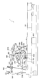
- FIG. 1 is a side view showing a mechanical configuration of a keyboard apparatus according to an embodiment of the present invention.
- the keyboard device 1 according to the first embodiment of the present invention includes a plurality of keys 110 (88 keys in this example) and an action mechanism corresponding to each of the keys 110.
- the action mechanism includes a support assembly 20, a hammer shank 310, a hammer 320 and a hammer stopper 410.
- FIG. 1 shows the case where the key 110 is a white key, the same applies to a black key.
- terms representing directions such as the player's front side, the player's back side, the upper side, the lower side, and the side are defined as directions when the keyboard device is viewed from the player side.
- the support assembly 20 is disposed on the front side of the performer when viewed from the hammer 320 and is disposed above when viewed from the key 110.
- the side corresponds to the direction in which the keys 110 are arranged.
- the key 110 is rotatably supported by the balance rail 910.
- the key 110 rotates in the range from the rest position to the end position shown in FIG.
- the key 110 includes a capstan screw 120.
- the support assembly 20 is rotatably connected to the support flange 290 and is placed on the capstan screw 120.
- the support flange 290 is fixed to the support rail 920.
- the detailed configuration of the support assembly 20 will be described later.
- the support flange 290 and the support rail 920 are examples of a frame that serves as a reference for rotation of the support assembly 20.
- the frame may be formed of a plurality of members such as the support flange 290 and the support rail 920, or may be formed of one member.
- the frame may be a rail-like member having a length in the arrangement direction of the keys 110 like the support rail 920, or may be a member independent for each key 110 like the support flange 290.
- the hammer shank 310 is rotatably connected to the shank flange 390.
- the hammer shank 310 includes a hammer roller 315.
- the hammer shank 310 is placed on the support assembly 20 via a hammer roller 315.
- the shank flange 390 is fixed to the shank rail 930.
- the hammer 320 is fixed to the end of the hammer shank 310.
- the regulating button 360 is fixed to the shank rail 930.
- the hammer stopper 410 is fixed to the hammer stopper rail 940 and is disposed at a position where the rotation of the hammer shank 310 is restricted.
- the sensor 510 is a sensor for measuring the position and moving speed of the hammer shank 310 (particularly the speed immediately before the hammer shank 310 collides with the hammer stopper 410).
- the sensor 510 is fixed to the sensor rail 950.
- the sensor 510 is a photo interrupter.
- the output value from the sensor 510 changes according to the amount by which the shielding plate 520 fixed to the hammer shank 310 shields the optical axis of the photo interrupter. Based on this output value, the position and moving speed of the hammer shank 310 can be measured.
- a sensor for measuring the operation state of the key 110 may be provided.
- the above-described support rail 920, shank rail 930, hammer stopper rail 940, and sensor rail 950 are supported by the bracket 900.
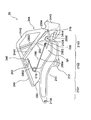
- FIG. 2 is a side view showing the configuration of the support assembly according to the embodiment of the present invention.
- the support assembly 20 includes a support 210, a repetition lever 240, a jack 250, and a torsion coil spring 280.
- the support 210 and the repetition lever 240 are coupled via the flexible portion 220.
- the repetition lever 240 is supported by the flexible portion 220 so as to be rotatable with respect to the support 210.
- the support assembly 20 is a resin structure manufactured by injection molding or the like except for the cushioning material (nonwoven fabric, elastic body, etc.) provided at the portion that collides with the torsion coil spring 280 and other members.
- the support 210 and the repetition lever 240 are integrally formed. Note that the support 210 and the repetition lever 240 may be formed as separate parts and bonded or joined together.
- the support 210 has a through hole 2109 formed on one end side and a jack support portion 2105 formed on the other end side.
- the support 210 includes a support heel 212 protruding downward and a spring support 218 protruding upward between the through hole 2109 and the jack support 2105.
- the through hole 2109 passes through the shaft supported by the support flange 290.
- the support heel 212 is in contact with the capstan screw 120 described above on its lower surface.
- the spring support 218 supports the torsion coil spring 280.
- the jack support part 2105 supports the jack 250 so that rotation is possible.
- a space SP exists on the jack support 2105 side from the support heel 212.
- the support 210 divides the first main body portion 2101, the bent portion 2102, and the second main body portion 2103 from the through hole 2109 side.
- the second main body 2103 is arranged closer to the key 110 (downward) than the first main body 2101 by the bent portion 2102 that connects the first main body 2101 and the second main body 2103.
- the jack support 2105 protrudes upward from the second main body 2103.
- the space SP corresponds to a region sandwiched between the bent portion 2102 and the jack support portion 2105 above the second main body portion 2103.
- a stopper 216 is coupled to the end of the support 210 (the end on the second main body 2103 side).
- a spring contact portion 242 and an extension portion 244 are coupled to the repetition lever 240.
- the spring contact portion 242 and the extending portion 244 extend from the repetition lever 240 to the support 210 side.
- the spring contact portion 242 contacts the first arm 2802 of the torsion coil spring 280.
- the repetition lever 240 and the extending portion 244 include two plate-like members that are sandwiched from both sides of the jack 250. In this example, the extending portion 244 and the jack 250 are in sliding contact with each other in at least a part of the space sandwiched between the two plate-like members.
- the extended portion 244 includes an inner portion 2441, an outer portion 2442, a coupling portion 2443 and a stopper contact portion 2444.
- the inner portion 2441 is coupled to the player back side (flexible portion 220 side) with respect to the large jack 2502 in the repetition lever 240.
- a rib 246 is provided at a portion where the inner portion 2441 and the repetition lever 240 are coupled.
- the inside portion 2441 intersects with the jack large 2502 interposed therebetween, and extends to the player's front side (the side opposite to the flexible portion 220) from the jack large 2502. That is, it can be said that the extended portion 244 intersects the jack 250.
- One or both of the inner portion 2441 and the large jack 2502 may be provided with a protrusion that reduces the contact area between the two.
- the protrusion may be point-shaped or linear.
- the outer portion 2442 is coupled to the player's front side (opposite to the flexible portion 220) with respect to the jack 250 (jack size 2502) in the repetition lever 240.
- Inner portion 2441 is coupled to outer portion 2442 at coupling portion 2443.
- the connecting portion 2443 sandwiches the small jack 2504 from both side surfaces.
- one or both of the coupling portion 2443 and the small jack 2504 may be provided with a protrusion that reduces the contact area between the two.
- the protrusion may be point-shaped or linear.
- the stopper contact portion 2444 is coupled to the coupling portion 2443 and contacts the stopper 216 from below the stopper 216. That is, the stopper 216 restricts the rotation range of the repetition lever 240 in the direction (upward) in which the repetition lever 240 and the support 210 expand.
- the extended portion 244 is connected to the repetition lever 240 on the jack 250 side from the rotation center of the repetition lever 240 and contacts the stopper 216 from below the stopper 216.
- the stopper 216 is connected to the support 210 below the rotation center of the jack 250.
- the jack 250 includes a large jack 2502, a small jack 2504, and a protruding portion 256.
- the jack 250 is disposed so as to be rotatable with respect to the support 210.
- a support connecting portion 2505 is formed to be rotatably supported by the jack support portion 2105.
- the support connection portion 2505 has a shape surrounding a part of the jack support portion 2105 and restricts the rotation range of the jack 250. Further, the jack 250 can be fitted from above the jack support portion 2105 by the shape of the support connection portion 2505 and the elastic deformation of the material.
- the protruding portion 256 protrudes from the large jack 2502 to the opposite side of the small jack 2504 and rotates together with the jack 250.
- the protruding portion 256 includes a spring contact portion 2562 on its side surface. The spring contact portion 2562 contacts the second arm 2804 of the torsion coil spring 280.
- the torsion coil spring 280 has the spring support portion 218 as a fulcrum, the first arm 2802 is in contact with the spring contact portion 242, and the second arm 2804 is in contact with the spring contact portion 2562.
- the first arm 2802 functions as an elastic body that applies rotational force to the repetition lever 240 via the spring contact portion 242 so that the player side of the repetition lever 240 moves upward (in a direction away from the support 210).
- the second arm 2804 functions as an elastic body that imparts rotational power to the jack 250 via the spring contact portion 2562 so that the protruding portion 256 moves downward (in the direction approaching the support 210).
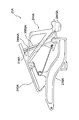
- FIG. 3 is a side view for explaining the movement of the support assembly according to the embodiment of the present invention.
- the capstan screw 120 pushes up the support heel 212 to rotate the support 210 around the axis of the through hole 2109.
- the large jack 2502 pushes up the hammer roller 315 and the hammer shank 310 collides with the hammer stopper 410. In the case of a general grand piano, this collision is equivalent to hammering by a hammer.
- the support 210 (jack support portion 2105) is further raised while the upward movement of the small jack 2504 is restricted by the regulating button 360. Therefore, the large jack 2502 rotates so as to be detached from the hammer roller 315. At this time, the upward movement of the coupling portion 2443 is also restricted by the regulating button 360.
- the regulating button 360 also has a function of a repetition regulating screw in a general grand piano action mechanism.
- FIG. 3 is a diagram showing this state.
- the key 110 is returned to the rest position, the hammer roller 315 is supported by the repetition lever 240, and the large jack 2502 is returned below the hammer roller 315.
- the keyboard device 1 According to the first embodiment of the present invention, it is possible to reduce the number of parts constituting the support assembly while ensuring the operation of the support assembly equivalent to the conventional one. Therefore, since the double escapement is realized with a simpler structure than a support assembly used for a general grand piano, it is possible to reduce the manufacturing cost while suppressing the influence on the touch feeling.
- the extending portion 244 comes into contact with the stopper from below the stopper and restricts the rotation of the repetition lever 240. Since the extending portion 244 is provided on the jack 250 side from the rotation center of the repetition lever 240, it is not necessary to provide a repetition lever button that restricts the rotation of the repetition lever, which has been necessary in the past, and thus the repetition lever 240 is provided. Can be supported by the flexible portion 220. By adopting a structure in which the repetition lever 240 is supported by the flexible portion 220, the number of parts can be reduced as compared with the conventional case.
- the extended portion 244 extends from the repetition lever 240 toward the support 210, and a space-saving support assembly can be realized by engaging with the stopper 216 connected to the support 210.
- the jack 250 is in sliding contact with the extending portion 244 at one or both of the intersection of the inner portion 2441 and the jack large 2502 and the intersection of the coupling portion 2443 and the small jack 2504, the jack 250 is in the repetition lever 240. (And also functions as a guide for the extended portion 244). Therefore, even if the repetition lever 240 is easily connected to the support 210 via the flexible portion 220, yawing (lateral displacement) and rolling (twisting) of the repetition lever 240 are likely to occur. Occurrence of the phenomenon can be suppressed. That is, the repetition lever 240 can be rotated along the surface on which the jack 250 rotates. In addition, by allowing the jack 250 to rotate along the surface on which the support 210 rotates, the repetition lever 240 can be rotated along the surface on which the support 210 rotates.
- the stopper 216 is connected to the support 210 below the rotation center of the jack 250, the stopper 216 can be provided without greatly changing the shape of the support 210.
- the keyboard device 1 is an application example to an electronic piano as described above, and measures the operation of the key 110 by the sensor 510 and outputs a sound corresponding to the measurement result.
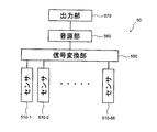
- FIG. 4 is a block diagram showing the configuration of the sound generation mechanism of the keyboard device according to one embodiment of the present invention.
- the sound generation mechanism 50 of the keyboard device 1 includes a sensor 510 (sensors 510-1, 510-2,... 510-88 corresponding to 88 keys 110), a signal conversion unit 550, a sound source unit 560, and an output unit 570.
- the signal conversion unit 550 acquires the electrical signal output from the sensor 510, generates an operation signal corresponding to the operation state of each key 110, and outputs the operation signal.
- the operation signal is a MIDI signal.
- the signal conversion unit 550 outputs note-on corresponding to the timing when the hammer shank 310 collides with the hammer stopper 410 by the key pressing operation. At this time, the key number indicating which of the 88 keys 110 has been operated and the velocity corresponding to the velocity immediately before the collision are also output in association with the note-on.
- the signal conversion unit 550 outputs the key number and the note-off in association with each other at the timing when the vibration of the string is stopped by the damper.
- a signal corresponding to another operation such as a pedal may be input to the signal conversion unit 550 and reflected in the operation signal.
- the sound source unit 560 generates a sound signal based on the operation signal output from the signal conversion unit 550.
- the output unit 570 is a speaker or a terminal that outputs the sound signal generated by the sound source unit 560.
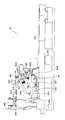
- FIG. 5 is a side view showing a configuration of a support assembly according to a modification of the embodiment of the present invention.
- a support assembly 20A shown in FIG. 5 is similar to the support assembly 20 shown in FIG.
- the support assembly 20 is different from the support assembly 20 in that it includes a stopper contact portion 2444A.
- the stopper 216A is provided at a position where it can be locked to the stopper contact portion 2444A, and restricts the rotation range of the repetition lever 240A.
- the stopper contact portion 2444A contacts the stopper 216A from below the stopper 216A, thereby restricting the rotation of the repetition lever 240A.
- the stopper that restricts the rotation range of the repetition lever 240A may be provided on a component other than the support 210A.
- a keyboard device 1B according to the second embodiment of the present invention is an example in which an example of a support assembly according to the present invention is applied to an electronic piano, similarly to the keyboard device 1 according to the first embodiment.
- the keyboard device 1B is similar to the keyboard device 1, but the support assembly and the support structure of the support assembly are different. Further, the keyboard device 1B is different from the keyboard device 1 in a method of restricting the upward rotation of the repetition lever provided in the support assembly. In the following description, the differences will be mainly described, and description of common parts will be omitted.
- FIG. 6 is a side view showing the configuration of the keyboard device according to the embodiment of the present invention.
- the support assembly 60 is fixed to the support rail 960.
- the support rail 960 is supported by the bracket 900.
- the shaft supported by the support flange 290 passes through the through hole 2109 and is supported so as to be rotatable.
- the support assembly 60 is the same as the support assembly 20 in that the support 610 is rotatably supported by the support rail 960, but the support method is different as described later.
- the repetition regulating screw 346 restricts the rotation of the support assembly 60 upward (on the hammer shank 330 side).
- the support rail 960 is an example of a frame that serves as a reference for rotation of the support assembly 60.
- the frame may be formed of one member like the support rail 960 or may be formed of a plurality of members.
- the frame may be a rail-like member having a length in the arrangement direction of the keys 110 like the support rail 960, or may be a member independent for each key 110.
- FIG. 7 is a side view showing a configuration of a support assembly according to an embodiment of the present invention.
- the support assembly 60 of the keyboard device 1B includes a support 610, a repetition lever 640, a jack 650, an operation restricting portion 660, and a coil spring 680.
- the support assembly 60 is a resin structure manufactured by injection molding or the like except for a cushioning material (nonwoven fabric, elastic body, etc.) provided at a portion that collides with the coil spring 680 and other members.
- the support 610 is supported so as to be rotatable with respect to the support rail 960.
- the repetition lever 640 is rotatably supported by the support 610.
- the jack 650 is rotatably disposed on the support 610.
- the jack 650 has a large jack 6502 and a small jack 6504.
- the large jack 6502 is disposed so as to be able to pass through a slit 642 provided in the repetition lever 640.
- the small jack 6504 extends from the support 610 toward the player.
- the operation restricting portion 660 is disposed on the side of the support lever 640 that is the repetition lever 640.
- the support 610 includes a support heel 612, a frame fixing portion 632, a flexible portion 634, and a base 638.
- the frame fixing unit 632 fixes the support 610 to the support rail 960.
- the flexible portion 634 is provided between the support 610 and the frame fixing portion 632 of each support assembly 60 and has flexibility (elasticity).
- the flexible portion 634 is formed integrally with the support 610 and the frame fixing portion 632.
- the flexible portion 634 is thinner than at least the support 610 in the rotation direction of the support assembly 60 or the thickness direction of the flexible portion 634.
- 7 illustrates the structure in which the support 610, the frame fixing portion 632, and the flexible portion 634 are integrally formed, the present invention is not limited to this structure.
- the flexible portion 634 may be fixed to both or one of the support 610 and the frame fixing portion 632 by a fixture, an adhesive, welding, or the like.
- the flexible portion 634 serves as a rotation center of the support assembly 60.
- the pedestal 638 is connected to the repetition lever 640 side of the support 610.
- a coil spring 682 acting on the pedestal 638 and the repetition lever 640 is provided on the upper surface of the pedestal 638 (on the side of the repetition lever 640).
- the coil spring 682 is a compression spring that acts on the pedestal 638 and the repetition lever 640 in a direction in which the pedestal 638 and the repetition lever 640 are separated from each other and functions as an elastic body that imparts rotational force to the repetition lever 640.
- the repetition lever 640 includes a flexible portion 620, a slit 642, an extending portion 644, and a support fixing portion 648.
- the flexible portion 620 extends to the support 610 side of the repetition lever 640 and is coupled to the support fixing portion 648. That is, the flexible portion 620 is provided between the repetition lever 640 and the support fixing portion 648.
- the flexible portion 620 is integrally formed with the support fixing portion 648 and the repetition lever 640. Since the plate thickness of the flexible portion 620 is thinner than the plate thickness of the repetition lever 640, the flexible portion 620 has flexibility (elasticity). Therefore, the repetition lever 640 rotates around the flexible portion 620.
- the slit 642 is provided at a position where the large jack 6502 can pass through a part of the player's front side from the flexible portion 620 that is the rotation center of the repetition lever 640.
- the extending portion 644 is coupled to the support 610 side of the repetition lever 640 on the jack 650 side from the flexible portion 620 that is the rotation center of the repetition lever 640. Further, the extending portion 644 has slits 6442 and 6444.
- the support fixing portion 648 is fixed to the support 610 by a fixing tool 674.
- the present invention is not limited to this structure.
- the flexible part 620 may be fixed to both or one of the repetition lever 640 and the support fixing part 648 by a fixture, an adhesive, welding, or the like.
- the jack 650 is disposed so as to be rotatable with respect to the support 610 in a jack support portion 6105 between the jack large 6502 and the jack small 6504.
- a part of the jack large 6502 is provided with a coil spring 684 acting on the jack large 6502 and the support 610.
- the coil spring 684 is a tension spring that acts on the jack large 6502 and the support 610 in a direction in which the jack large 6502 approaches the pedestal 638 and functions as an elastic body that imparts rotational force to the jack 650.
- the operation restricting portion 660 is provided on the opposite side of the flexible portion 634 with respect to the flexible portion 620.
- the operation restricting portion 660 includes an extending portion 662 (second extending portion), a stopper 664, and a guide 666.
- the extending portion 662 is disposed on the side of the repetition lever 640 of the support 610.
- the stopper 664 and the guide 666 are disposed on the extended portion 662 and extend from the extended portion 662 toward the player. In other words, it can be said that the stopper 664 and the guide 666 are protrusions that protrude from the extended portion 662 toward the player.
- the stopper 664 passes through the slit 6442 provided in the extending portion 644 (first extending portion).
- the guide 666 passes through a slit 6444 provided in the extending portion 644.
- the slits 6442 and 6444 may have any shape as long as the stopper 664 and the guide 666 can be locked.
- the slits 6442 and 6444 may have a shape provided with a groove in which the stopper 664 and the guide 666 can be locked.
- the slits 6442 and 6444 can also be referred to as locking portions.
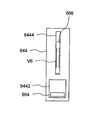
- FIGS. 8A and 8B are side views showing the structure of the stopper and guide of the support assembly according to the embodiment of the present invention.
- the side views shown in FIGS. 8A and 8B are views showing only the extending portion 644, the stopper 664, and the guide 666 in the side view seen from the direction D1 in FIG. 8A is a side view of the rest position, and FIG. 8B is a side view of the end position.
- the stopper 664 has a length in the direction intersecting the rotation direction of the repetition lever 640 and the extending portion 644.
- the guide 666 and the slit 6444 are long in the rotation direction of the repetition lever 640 and the extending portion 644. Since the guide 666 has the groove V6 with respect to the inner wall of the slit 6444, the area where the guide 666 and the slit 6444 are in sliding contact with each other is small. Grease may be applied to the groove V6.
- the extending portion 644 is in contact with the stopper 664 from the support 610 side (downward) of the stopper 664 in the slit 6442.
- the extending portion 644 is in contact with the operation restricting portion 660 from below the operation restricting portion 660. That is, the stopper 664 or the operation restricting portion 660 restricts the rotation of the repetition lever 640 and the extending portion 644 toward the hammer shank 310 (upward). Even if a buffer material or the like (nonwoven fabric, elastic body, etc.) is provided between the extended portion 644 and the stopper 664 to reduce noise generated when the extended portion 644 and the stopper 664 come into contact with each other. Good.
- the extending portion 644 is in contact with the guide 666 from the side at the slit 6444.
- the side is a direction in which the support assemblies 60 are adjacent to each other, or a direction in which the support rail 960 is extended.
- the extended portion 644 is in contact with the operation restricting portion 660 from the side. That is, the guide 666 or the operation restricting unit 660 suppresses yawing and rolling of the repetition lever 640.
- Grease may be applied between the extending portion 644 and the guide 666 so that the extending portion 644 and the guide 666 can slide smoothly.
- a slit is provided in the extending portion 644 connected to the repetition lever 640, and a protruding portion is provided in the extending portion 662 connected to the support 610.
- the present invention is not limited to this configuration.
- the extending portion 662 may be provided with a slit, and the extending portion 644 may have a protruding portion that passes through the slit.
- the keyboard device 1B According to the keyboard device 1B according to the second embodiment of the present invention, it is possible to reduce the number of parts constituting the support assembly while ensuring the operation of the support assembly equivalent to the conventional one. Therefore, it is possible to reduce the manufacturing cost of the support assembly while suppressing a change in touch feeling when operating the key.
- the guide 666 and the extended portion 644 are in sliding contact, the guide 666 also functions as a guide portion of the repetition lever 640 coupled to the extended portion 644. Therefore, occurrence of yawing and rolling of the repetition lever 640 can be suppressed.
- FIG. 9 is a side view for explaining the movement of the support assembly according to the embodiment of the present invention.
- the capstan screw 120 pushes up the support heel 612 to rotate the support 610 about the axis of the flexible portion 634.
- the large jack 6502 pushes up the hammer roller 315 and the hammer shank 310 collides with the hammer stopper 410.
- FIG. 9 is a diagram showing this state.
- the configuration in which the stopper is provided on the front side of the performer from the jack size is illustrated, but the stopper is provided between the jack size and the flexible portion that is the rotation center of the repetition lever. Also good.
- the configuration in which the stopper is provided separately from the support is illustrated, but the stopper may not be provided separately from the support.
- An extending portion connected to the support side from the repetition lever may extend to the lower side of the support, and a part of the support may function as a stopper.
- the repetition lever is coupled to the support via the flexible portion.
- the extending portion can be coupled to a repetition lever of a support assembly used in a conventional grand piano.
- an extension part can be made to contact from the lower part of a stopper with respect to the member (stopper) couple
- the first embodiment and the second embodiment are described as examples, and according to one embodiment of the present invention, a change in touch feeling when operating keys is compared with a keyboard device of an acoustic piano.
- the manufacturing cost of the support assembly can be reduced while restraining.
- an electronic piano is shown as an example of a keyboard device to which the support assembly is applied.
- the support assembly of the above embodiment can also be applied to a grand piano (acoustic piano).
- the sound generation mechanism corresponds to a hammer and a string.
Landscapes
- Physics & Mathematics (AREA)
- Engineering & Computer Science (AREA)
- Acoustics & Sound (AREA)
- Multimedia (AREA)
- Electrophonic Musical Instruments (AREA)
Abstract
サポートアセンブリは、フレームに対して回動可能に配置されたサポートと、サポートに対して回動可能に配置されたレペティションレバーと、レペティションレバーの回動中心からジャック側においてレペティションレバーに配置され、レペティションレバーの上方への回動を規制するストッパに対してストッパの下方から接する第1延設部と、を有する。
Description
本発明は、鍵盤装置に用いるサポートアセンブリに関する。
従来のグランドピアノやアップライトピアノなどのアコースティックピアノは、多くの部品によって構成されている。また、これらの部品の組み立ては非常に複雑であるため、組み立て作業にかかる時間が長い。特に、各鍵に対応して設けられるアクション機構は、多くの部品を必要とするため、その組み立て作業が非常に複雑である。
例えば、特開2005-292361号公報に示すアクション機構は、複数の部品が互いに作用して、押鍵および離鍵による鍵の動作がハンマに伝達される。特に、アクション機構の一部を構成するサポートアセンブリは、様々な部品が組み合わされて動作する。サポートアセンブリは押鍵に応じてハンマによる打弦を実現する機構だけでなく、打弦直前に鍵の動作によりハンマへ伝達される力を解放させるためのエスケープメント機構を有している。この機構は、アコースティックピアノの基本的な動作を実現するための重要な機構である。特に、グランドピアノでは、一般的に、レペティションレバーとジャックとを組み合わせたダブルエスケープメント機構が採用されている。
アクション機構の動作は、鍵を通して演奏者の指に感覚(以下、タッチ感という)を与える。特に、サポートアセンブリの構成は、タッチ感に重要な影響を与えている。例えば、エスケープメント機構の動作によるタッチ感は、レットオフといわれる。
サポートアセンブリを構成する各部品の数が多いため、製造期間が長期化し、製造コストが上昇してしまう。そのため、製造コストを低減しようとして、単純に、部品数を減らしたり、構造を簡略化したりすることが望まれている。しかしながら、サポートアセンブリの構成を変更すると、鍵の操作時のタッチ感が大きく変化してしまう。そのため、アコースティックピアノの製造費用を抑えることは困難である。
本発明の目的の一つは、アコースティックピアノの鍵盤装置と比較して、鍵の操作時のタッチ感の変化を抑えつつ、サポートアセンブリの製造コストを低減することにある。
本発明の一実施形態に係るサポートアセンブリは、フレームに対して回動可能に配置されたサポートと、サポートに対して回動可能に配置されたレペティションレバーと、レペティションレバーの回動中心からジャック側においてレペティションレバーに配置され、レペティションレバーの上方への回動を規制するストッパに対してストッパの下方から接する第1延設部と、を有する。
サポートに対してレペティションレバーを回動可能に支持する可撓部をさらに有してもよい。
第1延設部は、レペティションレバーからサポート側へ延びていてもよい。
第1延設部は、ジャックと交差していてもよい。
ストッパは、ジャックの回動中心よりも下方において、サポートに配置されていてもよい。
サポートおよびストッパに配置され、サポートからレペティションレバー側に延びる第2延設部をさらに有してもよい。
第1延設部および第2延設部のうち一方は突出部を有し、第1延設部および第2延設部のうち他方は突出部が係止する係止部を有してもよい。
以下、本発明の一実施形態におけるサポートアセンブリを含む鍵盤装置について、図面を参照しながら詳細に説明する。以下に示す実施形態は本発明の実施形態の一例であって、本発明はこれらの実施形態に限定して解釈されるできではない。なお、本実施形態で参照する図面において、同一部分または同様な機能を有する部分には同一の符号または類似の符号(数字の後にA、B等を付しただけの符号)を付し、その繰り返しの説明は省略する場合がある。また、図面の寸法比率(各構成間の比率、縦横高さ方向の比率等)は説明の都合上実際の比率とは異なったり、構成の一部が図面から省略されたりする場合がある。
〈第1実施形態〉
[鍵盤装置1の構成]
本発明の第1実施形態における鍵盤装置1は、本発明に係るサポートアセンブリの一例を電子ピアノに適用した例である。この電子ピアノは、鍵の操作時にグランドピアノに近いタッチ感を得るために、グランドピアノが備えているサポートアセンブリに近い構成を備えている。図1を用いて、本発明の第1実施形態に係る鍵盤装置1の概要を説明する。
[鍵盤装置1の構成]
本発明の第1実施形態における鍵盤装置1は、本発明に係るサポートアセンブリの一例を電子ピアノに適用した例である。この電子ピアノは、鍵の操作時にグランドピアノに近いタッチ感を得るために、グランドピアノが備えているサポートアセンブリに近い構成を備えている。図1を用いて、本発明の第1実施形態に係る鍵盤装置1の概要を説明する。
図1は、本発明の一実施形態に係る鍵盤装置の機械構成を示す側面図である。図1に示すように、本発明の第1実施形態に係る鍵盤装置1は、複数の鍵110(この例では88鍵)および鍵110の各々に対応したアクション機構を備える。アクション機構は、サポートアセンブリ20、ハンマシャンク310、ハンマ320およびハンマストッパ410を備える。なお、図1では、鍵110が白鍵である場合を示しているが、黒鍵であっても同様である。また、以下の説明において、演奏者手前側、演奏者奥側、上方、下方、側方等の向きを表す用語は、鍵盤装置を演奏者側から見た場合の向きとして定義される。例えば、図1に示す例において、サポートアセンブリ20は、ハンマ320から見て演奏者手前側に配置され、鍵110から見て上方に配置されている。側方は、鍵110が配列される方向に対応する。
鍵110は、バランスレール910によって回動可能に支持されている。鍵110は、図1に示すレスト位置からエンド位置までの範囲で回動する。鍵110は、キャプスタンスクリュー120を備えている。サポートアセンブリ20は、サポートフレンジ290に回動可能に接続され、キャプスタンスクリュー120上に載置されている。サポートフレンジ290は、サポートレール920に固定されている。サポートアセンブリ20の詳細の構成は後述する。なお、サポートフレンジ290およびサポートレール920は、サポートアセンブリ20の回動の基準となるフレームの一例である。フレームは、サポートフレンジ290およびサポートレール920のように複数の部材で形成されていてもよいし、一つ部材で形成されていてもよい。フレームは、サポートレール920のように鍵110の配列方向に長手を有するレール状の部材であってもよいし、サポートフレンジ290のように鍵110毎に独立した部材であってもよい。
ハンマシャンク310は、シャンクフレンジ390に回動可能に接続されている。ハンマシャンク310は、ハンマローラ315を備えている。ハンマシャンク310は、ハンマローラ315を介して、サポートアセンブリ20上に載置されている。シャンクフレンジ390は、シャンクレール930に固定されている。ハンマ320は、ハンマシャンク310の端部に固定されている。レギュレーティングボタン360は、シャンクレール930に固定されている。ハンマストッパ410は、ハンマストッパレール940に固定されて、ハンマシャンク310の回動を規制する位置に配置されている。
センサ510は、ハンマシャンク310の位置および移動速度(特にハンマシャンク310がハンマストッパ410に衝突する直前の速度)を測定するためのセンサである。センサ510は、センサレール950に固定されている。この例では、センサ510はフォトインタラプタである。ハンマシャンク310に固定された遮蔽板520がフォトインタラプタの光軸を遮蔽する量に応じて、センサ510からの出力値が変化する。この出力値に基づいて、ハンマシャンク310の位置および移動速度を測定することができる。なお、センサ510に代えて、またはセンサ510と共に、鍵110の操作状態を測定するためのセンサが設けられてもよい。
上述したサポートレール920、シャンクレール930、ハンマストッパレール940およびセンサレール950は、ブラケット900に支持されている。
[サポートアセンブリ20の構成]
図2は、本発明の一実施形態に係るサポートアセンブリの構成を示す側面図である。サポートアセンブリ20は、サポート210、レペティションレバー240、ジャック250、ねじりコイルスプリング280を備える。サポート210とレペティションレバー240とは、可撓部220を介して結合している。可撓部220によって、レペティションレバー240は、サポート210に対して回動可能に支持されている。サポートアセンブリ20のうち、ねじりコイルスプリング280および他の部材と衝突する部分に設けられた緩衝材等(不織布、弾性体等)以外は、射出成形などによって製造された樹脂製の構造体である。この例では、サポート210およびレペティションレバー240は一体形成されている。なお、サポート210およびレペティションレバー240を個別の部品として形成し、それらを接着または接合させてもよい。
図2は、本発明の一実施形態に係るサポートアセンブリの構成を示す側面図である。サポートアセンブリ20は、サポート210、レペティションレバー240、ジャック250、ねじりコイルスプリング280を備える。サポート210とレペティションレバー240とは、可撓部220を介して結合している。可撓部220によって、レペティションレバー240は、サポート210に対して回動可能に支持されている。サポートアセンブリ20のうち、ねじりコイルスプリング280および他の部材と衝突する部分に設けられた緩衝材等(不織布、弾性体等)以外は、射出成形などによって製造された樹脂製の構造体である。この例では、サポート210およびレペティションレバー240は一体形成されている。なお、サポート210およびレペティションレバー240を個別の部品として形成し、それらを接着または接合させてもよい。
サポート210は、一端側に貫通孔2109が形成され、他端側にジャック支持部2105が形成されている。サポート210は、貫通孔2109とジャック支持部2105との間において、下方に突出するサポートヒール212および上方に突出するスプリング支持部218を備える。貫通孔2109は、サポートフレンジ290に支持される軸が通される。これによって、サポート210は、サポートフレンジ290およびサポートレール920に対して回動可能に配置される。サポートヒール212は、その下面において、上述したキャプスタンスクリュー120と接触する。スプリング支持部218は、ねじりコイルスプリング280を支持する。ジャック支持部2105は、ジャック250を回動可能に支持する。
貫通孔2109とジャック支持部2105との間には、サポートヒール212よりジャック支持部2105側において空間SPが存在する。説明の便宜上、サポート210が、貫通孔2109側から第1本体部2101、屈曲部2102、第2本体部2103の各領域に区分する。この場合、第1本体部2101と第2本体部2103とを結合する屈曲部2102によって、第2本体部2103は第1本体部2101よりも鍵110に近い側(下方)に配置される。ジャック支持部2105が第2本体部2103から上方に突出する。この区分によれば、上記の空間SPは、第2本体部2103の上方において、屈曲部2102とジャック支持部2105と挟まれた領域に対応する。また、サポート210の端部(第2本体部2103側の端部)には、ストッパ216が結合している。
レペティションレバー240には、スプリング接触部242および延設部244(第1延設部)が結合されている。スプリング接触部242および延設部244はレペティションレバー240からサポート210側へ延びている。スプリング接触部242は、ねじりコイルスプリング280の第1アーム2802と接触する。レペティションレバー240および延設部244は、ジャック250の両側面の側から挟み込む2枚の板状の部材を含む。この例では、この2枚の板状の部材によって挟まれた空間の少なくとも一部において、延設部244とジャック250とが摺接している。
延設部244は、内側部2441、外側部2442、結合部2443およびストッパ接触部2444を含む。内側部2441は、レペティションレバー240においてジャック大2502よりも演奏者奥側(可撓部220側)に結合されている。内側部2441とレペティションレバー240とが結合されている部分にはリブ246が設けられている。内側部2441は、ジャック大2502を挟み込んで交差し、ジャック大2502よりも演奏者手前側(可撓部220とは反対側)まで延在している。つまり、延設部244はジャック250と交差している、ということもできる。内側部2441およびジャック大2502の一方または両方に、両者の接触面積を小さくする突起部が設けられていてもよい。突起部は点形状であってもよく、線形状であってもよい。
外側部2442は、レペティションレバー240においてジャック250(ジャック大2502)よりも演奏者手前側(可撓部220とは反対側)に結合されている。内側部2441は、結合部2443において外側部2442に結合されている。結合部2443は、ジャック小2504を両側面から挟み込んでいる。ここで、結合部2443およびジャック小2504の一方または両方に、両者の接触面積を小さくする突起部が設けられていてもよい。突起部は点形状であってもよく、線形状であってもよい。
ストッパ接触部2444は、結合部2443に結合され、ストッパ216に対してストッパ216の下方から接触する。つまり、ストッパ216はレペティションレバー240とサポート210とが拡がる方向(上方)へのレペティションレバー240の回動範囲を規制する。換言すると、延設部244はレペティションレバー240の回動中心からジャック250側においてレペティションレバー240に接続され、ストッパ216に対してストッパ216の下方から接触する。ここで、ストッパ216はジャック250の回動中心よりも下方において、サポート210に接続されている。
ジャック250は、ジャック大2502、ジャック小2504および突出部256を備える。ジャック250は、サポート210に対して回動可能に配置されている。ジャック大2502とジャック小2504との間において、ジャック支持部2105に回動可能に支持されるためのサポート接続部2505が形成されている。サポート接続部2505は、ジャック支持部2105の一部を囲む形状であり、ジャック250の回動範囲を規制する。また、サポート接続部2505の形状とその素材の弾性変形により、ジャック250は、ジャック支持部2105の上方から嵌めることができる。突出部256は、ジャック大2502からジャック小2504とは反対側に突出し、ジャック250と共に回動する。突出部256は、その側面にスプリング接触部2562を備える。スプリング接触部2562は、ねじりコイルスプリング280の第2アーム2804と接触する。
ねじりコイルスプリング280は、スプリング支持部218を支点とし、第1アーム2802がスプリング接触部242と接触し、第2アーム2804がスプリング接触部2562と接触する。第1アーム2802は、レペティションレバー240の演奏者側を上方(サポート210から離れる方向)に移動するように、スプリング接触部242を介してレペティションレバー240に回動力を付与する弾性体として機能する。第2アーム2804は、突出部256が下方(サポート210に近づく方向)に移動するように、スプリング接触部2562を介してジャック250に回動力を付与する弾性体として機能する。以上が、サポートアセンブリ20の構成についての説明である。
[サポートアセンブリ20の動作]
続いて、鍵110がレスト位置にある状態(図1)からエンド位置に押下された場合において、サポートアセンブリ20の動きを説明する。
続いて、鍵110がレスト位置にある状態(図1)からエンド位置に押下された場合において、サポートアセンブリ20の動きを説明する。
図3は、本発明の一実施形態に係るサポートアセンブリの動きを説明するための側面図である。鍵110がエンド位置まで押下されると、キャプスタンスクリュー120がサポートヒール212を押し上げて、貫通孔2109の軸を回動中心としてサポート210を回動させる。サポート210が回動して上方に移動すると、ジャック大2502がハンマローラ315を押し上げて、ハンマシャンク310がハンマストッパ410に衝突する。なお、一般的なグランドピアノである場合には、この衝突は、ハンマによる打弦に相当する。
この衝突の直前に、レギュレーティングボタン360によってジャック小2504の上方への移動が規制されつつ、さらにサポート210(ジャック支持部2105)が上昇する。そのため、ジャック大2502は、ハンマローラ315から外れるように回動する。このとき、レギュレーティングボタン360によって、結合部2443の上方への移動も規制される。この例では、レギュレーティングボタン360は、一般的なグランドピアノのアクション機構におけるレペティションレギュレーティングスクリューの機能も有している。
これにより、レペティションレバー240は、上方への移動が規制されてサポート210に近づくように回動する。これらの動作によって、ダブルエスケープメント機構が実現される。図3は、この状態を示す図である。なお、鍵110をレスト位置に戻していくと、レペティションレバー240によってハンマローラ315が支えられ、ハンマローラ315の下方にジャック大2502が戻る。
以上のように、本発明の第1実施形態に係る鍵盤装置1によると、従来と同等のサポートアセンブリの動作を確保しつつサポートアセンブリを構成する部品数を低減することができる。したがって、一般的なグランドピアノに用いられるサポートアセンブリに比べて容易な構成において、ダブルエスケープメントが実現されるため、タッチ感への影響を抑えつつ製造コストを削減することができる。
また、延設部244はストッパに対してストッパの下方から接し、レペティションレバー240の回動を規制する。延設部244がレペティションレバー240の回動中心からジャック250側に設けられていることで、従来必要であったレペティションレバーの回動を規制するレペティションレバーボタンを設ける必要がなくなるため、レペティションレバー240を可撓部220で支持することができる。レペティションレバー240を可撓部220で支持する構造にすることによって、従来に比べて部品数を低減することができる。
また、延設部244がレペティションレバー240からサポート210側へ延びており、サポート210に接続されたストッパ216と係止することにより省スペースのサポートアセンブリを実現することができる。
また、ジャック250は、内側部2441およびジャック大2502の交差部と、結合部2443およびジャック小2504の交差部と、の一方または両方において延設部244と摺接するため、ジャック250がレペティションレバー240(および延設部244)のガイドとしても機能する。そのため、レペティションレバー240が可撓部220を介してサポート210に接続されていることに起因して、レペティションレバー240のヨーイング(横ずれ)およびローリング(捻れ)が生じやすくなっていたとしても、これらの現象の発生を抑制することができる。すなわち、ジャック250が回動する面に沿ってレペティションレバー240を回動させることができる。また、サポート210が回動する面に沿ってジャック250が回動するようにすることで、サポート210が回動する面に沿ってレペティションレバー240を回動させることができる。
また、ストッパ216がジャック250の回動中心よりも下方において、サポート210に接続されていることで、サポート210の形状を大きく変化させることなくストッパ216を設けることができる。
[鍵盤装置1の発音機構]
鍵盤装置1は、上述したように電子ピアノへの適用例であって、鍵110の操作をセンサ510によって測定し、測定結果に応じた音を出力する。
鍵盤装置1は、上述したように電子ピアノへの適用例であって、鍵110の操作をセンサ510によって測定し、測定結果に応じた音を出力する。
図4は、本発明の一実施形態に係る鍵盤装置の発音機構の構成を示すブロック図である。鍵盤装置1の発音機構50は、センサ510(88の鍵110に対応したセンサ510-1、510-2、・・・510-88)、信号変換部550、音源部560および出力部570を備える。信号変換部550は、センサ510から出力された電気信号を取得し、各鍵110における操作状態に応じた操作信号を生成して出力する。この例では、操作信号はMIDI形式の信号である。そのため、押鍵操作によってハンマシャンク310がハンマストッパ410に衝突したタイミングに対応して、信号変換部550はノートオンを出力する。このとき、88個の鍵110のいずれが操作されたかを示すキーナンバ、および衝突する直前の速度に対応するベロシティについてもノートオンに対応付けて出力される。一方、離鍵操作がされると、グランドピアノであればダンパによって弦の振動が止められるタイミングに対応して、信号変換部550はキーナンバとノートオフとを対応付けて出力する。信号変換部550には、ペダル等の他の操作に応じた信号が入力され、操作信号に反映されてもよい。音源部560は、信号変換部550から出力された操作信号に基づいて、音信号を生成する。出力部570は、音源部560によって生成された音信号を出力するスピーカまたは端子である。
〈第1実施形態の変形例〉
図5は、本発明の一実施形態の変形例に係るサポートアセンブリの構成を示す側面図である。図5に示すサポートアセンブリ20Aは、図2に示すサポートアセンブリ20と類似しているが、サポートアセンブリ20Aはストッパ216およびストッパ接触部2444の代わりにジャック大2502Aに設けられたピン状のストッパ216Aを備える点、およびストッパ接触部2444Aを備える点においてサポートアセンブリ20と相違する。ストッパ216Aは、ストッパ接触部2444Aに係止可能な位置に設けられており、レペティションレバー240Aの回動範囲を規制する。図5に示す状態では、ストッパ216Aに対してストッパ接触部2444Aがストッパ216Aの下方から接触することで、レペティションレバー240Aの上方への回動を規制する。上記のように、レペティションレバー240Aの回動範囲を規制するストッパはサポート210A以外の部品に設けられていてもよい。
図5は、本発明の一実施形態の変形例に係るサポートアセンブリの構成を示す側面図である。図5に示すサポートアセンブリ20Aは、図2に示すサポートアセンブリ20と類似しているが、サポートアセンブリ20Aはストッパ216およびストッパ接触部2444の代わりにジャック大2502Aに設けられたピン状のストッパ216Aを備える点、およびストッパ接触部2444Aを備える点においてサポートアセンブリ20と相違する。ストッパ216Aは、ストッパ接触部2444Aに係止可能な位置に設けられており、レペティションレバー240Aの回動範囲を規制する。図5に示す状態では、ストッパ216Aに対してストッパ接触部2444Aがストッパ216Aの下方から接触することで、レペティションレバー240Aの上方への回動を規制する。上記のように、レペティションレバー240Aの回動範囲を規制するストッパはサポート210A以外の部品に設けられていてもよい。
〈第2実施形態〉
[鍵盤装置1Bの構成]
本発明の第2実施形態における鍵盤装置1Bは、第1実施形態の鍵盤装置1と同様に本発明に係るサポートアセンブリの一例を電子ピアノに適用した例である。鍵盤装置1Bは鍵盤装置1と類似しているが、サポートアセンブリおよびサポートアセンブリの支持構造が相違している。また、鍵盤装置1Bはサポートアセンブリに備えられたレペティションレバーの上方への回動を規制する方法が鍵盤装置1とは相違している。以下の説明において、上記の相違点を中心に説明し、共通する部分については説明を省略する。
[鍵盤装置1Bの構成]
本発明の第2実施形態における鍵盤装置1Bは、第1実施形態の鍵盤装置1と同様に本発明に係るサポートアセンブリの一例を電子ピアノに適用した例である。鍵盤装置1Bは鍵盤装置1と類似しているが、サポートアセンブリおよびサポートアセンブリの支持構造が相違している。また、鍵盤装置1Bはサポートアセンブリに備えられたレペティションレバーの上方への回動を規制する方法が鍵盤装置1とは相違している。以下の説明において、上記の相違点を中心に説明し、共通する部分については説明を省略する。
図6は、本発明の一実施形態に係る鍵盤装置の構成を示す側面図である。サポートアセンブリ60はサポートレール960に固定されている。サポートレール960はブラケット900に支持されている。第1実施形態におけるサポートアセンブリ20では、サポートフレンジ290に支持される軸が貫通孔2109を貫通することによって、回動可能に支持されている。一方、サポートアセンブリ60では、サポート610がサポートレール960に回動可能に支持される点についてはサポートアセンブリ20と同様であるが、後述するように、その支持方法が異なっている。レペティションレギュレーティングスクリュー346は、サポートアセンブリ60の上方(ハンマシャンク330側)への回動を規制する。なお、サポートレール960は、サポートアセンブリ60の回動の基準となるフレームの一例である。フレームは、サポートレール960のように一つの部材で形成されていてもよいし、複数の部材で形成されていてもよい。フレームは、サポートレール960のように鍵110の配列方向に長手を有するレール状の部材であってもよいし、鍵110毎に独立した部材であってもよい。
[サポートアセンブリ60の構成]
図7は、本発明の一実施形態に係るサポートアセンブリの構成を示す側面図である。また、鍵盤装置1Bのサポートアセンブリ60は、サポート610、レペティションレバー640、ジャック650、動作規制部660、およびコイルスプリング680を備える。サポートアセンブリ60のうち、コイルスプリング680および他の部材と衝突する部分に設けられた緩衝材等(不織布、弾性体等)以外は、射出成形などによって製造された樹脂製の構造体である。
図7は、本発明の一実施形態に係るサポートアセンブリの構成を示す側面図である。また、鍵盤装置1Bのサポートアセンブリ60は、サポート610、レペティションレバー640、ジャック650、動作規制部660、およびコイルスプリング680を備える。サポートアセンブリ60のうち、コイルスプリング680および他の部材と衝突する部分に設けられた緩衝材等(不織布、弾性体等)以外は、射出成形などによって製造された樹脂製の構造体である。
サポート610は、サポートレール960に対して回動可能に支持されている。レペティションレバー640は、サポート610に回動可能に支持されている。ジャック650は、サポート610に回動可能に配置されている。ジャック650は、ジャック大6502およびジャック小6504を有している。ジャック大6502はレペティションレバー640に設けられたスリット642を貫通可能に配置されている。ジャック小6504はサポート610から演奏者の手前側に延びている。動作規制部660は、サポート610のレペティションレバー640側に配置されている。
また、サポート610は、サポートヒール612、フレーム固定部632、可撓部634、および台座638を有する。フレーム固定部632は、サポート610をサポートレール960に固定する。可撓部634は、各々のサポートアセンブリ60のサポート610とフレーム固定部632との間に設けられ、可撓性(弾性)を有している。また、可撓部634はサポート610およびフレーム固定部632と一体形成されている。可撓部634はサポートアセンブリ60の回動方向または可撓部634の板厚方向において、少なくともサポート610よりも板厚が薄い。なお、図7では、サポート610、フレーム固定部632、および可撓部634が一体形成された構造を例示したが、この構造に限定されない。例えば、可撓部634が固定具、接着剤、または溶接等によってサポート610およびフレーム固定部632の両方または一方に固定されていてもよい。ここで、可撓部634はサポートアセンブリ60の回動中心となる。
台座638は、サポート610のレペティションレバー640側に接続されている。台座638の上面(レペティションレバー640側)には、台座638およびレペティションレバー640に作用するコイルスプリング682が設けられている。コイルスプリング682は台座638およびレペティションレバー640が互いに離れる方向に台座638およびレペティションレバー640に作用し、レペティションレバー640に回動力を付与する弾性体として機能する圧縮スプリングである。
レペティションレバー640は、可撓部620、スリット642、延設部644、およびサポート固定部648を有する。
可撓部620はレペティションレバー640のサポート610側に延びておりサポート固定部648に結合されている。つまり、可撓部620は、レペティションレバー640とサポート固定部648との間に設けられている。可撓部620はサポート固定部648及びレペティションレバー640と一体形成されている。可撓部620の板厚がレペティションレバー640の板厚よりも薄いため、可撓部620は可撓性(弾性)を有している。したがって、レペティションレバー640は可撓部620を中心として回動する。
スリット642は、レペティションレバー640の回動中心である可撓部620から演奏者の手前側の一部において、ジャック大6502が貫通可能な位置に設けられている。延設部644は、レペティションレバー640の回動中心である可撓部620からジャック650側において、レペティションレバー640のサポート610側に結合されている。また、延設部644はスリット6442および6444を有している。サポート固定部648は固定具674によってサポート610に固定されている。
なお、図7ではレペティションレバー640、可撓部620、およびサポート固定部648が一体形成された構造を例示したが、この構造に限定されない。例えば、可撓部620が固定具、接着剤、または溶接等によってレペティションレバー640およびサポート固定部648の両方または一方に固定されていてもよい。
ジャック650は、ジャック大6502とジャック小6504との間のジャック支持部6105においてサポート610に対して回動可能に配置されている。ジャック大6502の一部には、ジャック大6502およびサポート610に作用するコイルスプリング684が設けられている。コイルスプリング684はジャック大6502が台座638に近づく方向にジャック大6502およびサポート610に作用し、ジャック650に回動力を付与する弾性体として機能する引張スプリングである。
動作規制部660は、可撓部620を基準に可撓部634とは反対側に設けられている。また、動作規制部660は、延設部662(第2延設部)、ストッパ664、およびガイド666を有する。延設部662はサポート610のレペティションレバー640側に配置されている。ストッパ664およびガイド666は延設部662に配置されており、それぞれ延設部662から演奏者の手前側に延びている。換言すると、ストッパ664およびガイド666は、延設部662から演奏者の手前側に突出する突出部である、ということもできる。ストッパ664は延設部644(第1延設部)に設けられたスリット6442を貫通している。ガイド666は延設部644に設けられたスリット6444を貫通している。なお、スリット6442および6444は、ストッパ664及びガイド666が係止可能な形状であればよく、例えばストッパ664及びガイド666が係止可能な溝が設けられた形状であってもよい。スリット6442および6444を係止部ということもできる。
図8(a)および図8(b)は、本発明の一実施形態に係るサポートアセンブリのストッパおよびガイドの構成を示す側面図である。図8(a)および図8(b)に示す側面図は図7においてD1方向から見た側面図のうち延設部644、ストッパ664、およびガイド666のみを示した図である。また、図8(a)はレスト位置の、図8(b)はエンド位置の側面図である。ストッパ664はレペティションレバー640および延設部644の回動方向に交差する方向に長手を有している。また、ガイド666およびスリット6444はレペティションレバー640および延設部644の回動方向に長手を有している。ガイド666はスリット6444の内壁に対して溝部V6を有しているため、ガイド666とスリット6444との摺接する面積は小さい。上記の溝部V6にグリスが塗布されてもよい。
ここで、図7および図8(a)に示すレスト位置の状態では、延設部644は、スリット6442において、ストッパ664に対してストッパ664のサポート610側(下方)から接している。換言すると、延設部644は動作規制部660に対して動作規制部660の下方から接している。つまり、ストッパ664または動作規制部660はレペティションレバー640および延設部644のハンマシャンク310側(上方)への回動を規制する。延設部644とストッパ664との間には、延設部644とストッパ664とが接触することによって発生する雑音を低減するための緩衝材等(不織布、弾性体等)が設けられていてもよい。
また、延設部644は、スリット6444において、ガイド666と側方から接している。ここで、側方とはサポートアセンブリ60が隣接する方向、またはサポートレール960の延長方向である。換言すると、延設部644は動作規制部660と側方から接している。つまり、ガイド666または動作規制部660はレペティションレバー640のヨーイングおよびローリングを抑制する。延設部644とガイド666との間には、延設部644とガイド666とが摺動を円滑にするためにグリスが塗布されていてもよい。
なお、図7、図8(a)および図8(b)ではレペティションレバー640に接続された延設部644にスリットが設けられ、サポート610に接続された延設部662に突出部が設けられた構成を例示したが、この構成に限定されない。例えば、延設部662にスリットが設けられ、延設部644に当該スリットを貫通する突出部が構成であってもよい。
以上のように、本発明の第2実施形態に係る鍵盤装置1Bによると、従来と同等のサポートアセンブリの動作を確保しつつサポートアセンブリを構成する部品数を低減することができる。したがって、鍵の操作時のタッチ感の変化を抑えつつ、サポートアセンブリの製造コストを低減することができる。
また、ガイド666と延設部644とが摺接しているため、ガイド666は、延設部644に結合したレペティションレバー640のガイド部としても機能する。そのため、レペティションレバー640のヨーイングおよびローリングの発生を抑制することができる。
[サポートアセンブリ60の動作]
続いて、鍵110がレスト位置にある状態(図6)からエンド位置に押下された場合において、サポートアセンブリ60の動きを説明する。
続いて、鍵110がレスト位置にある状態(図6)からエンド位置に押下された場合において、サポートアセンブリ60の動きを説明する。
図9は、本発明の一実施形態に係るサポートアセンブリの動きを説明するための側面図である。鍵110がエンド位置まで押下されると、キャプスタンスクリュー120がサポートヒール612を押し上げて、可撓部634の軸を回動中心としてサポート610を回動させる。サポート610が回動して上方に移動すると、ジャック大6502がハンマローラ315を押し上げて、ハンマシャンク310がハンマストッパ410に衝突する。
この衝突の直前に、レギュレーティングボタン360によってジャック小6504の上方への移動が規制されつつ、さらにサポート610(ジャック支持部6105)が上昇する。そのため、ジャック大6502は、ハンマローラ315から外れるように回動する。このとき、レペティションレギュレーティングスクリュー346によって、レペティションレバー640の上方への移動が規制される。これにより、レペティションレバー640は、上方への移動が規制されてサポート610に近づくように回動する。これらの動作によって、ダブルエスケープメント機構が実現される。図9は、この状態を示す図である。なお、鍵110をレスト位置に戻していくと、レペティションレバー640によってハンマローラ315が支えられ、ハンマローラ315の下方にジャック大6502が戻る。
このようなサポートアセンブリ60であっても、サポートアセンブリ20と同様な効果が得られる。すなわち、一般的なグランドピアノに用いられるサポートアセンブリに比べて容易な構成において、ダブルエスケープメントが実現されるため、タッチ感への影響を抑えつつ製造コストを削減することができる。
上述した実施形態では、ジャック大よりも演奏者の手前側にストッパが設けられた構成について例示したが、ジャック大とレペティションレバーの回動中心となる可撓部との間にストッパが設けられてもよい。
上述した実施形態では、サポートとは別にストッパが設けられた構成について例示したが、サポートと別個にストッパが設けられていなくてもよい。レペティションレバーからサポート側に接続された延設部がサポートの下方まで延び、サポートの一部をストッパとして機能させてもよい。
上述した実施形態では、レペティションレバーは、サポートに対して可撓部を介して結合されていた。一方、従来のグランドピアノにおいて用いられるサポートアセンブリのレペティションレバーに対して、延設部を結合させることもできる。そして、サポートまたはジャックに結合した部材(ストッパ)に対して、延設部をストッパの下方から接触させることができる。
以上、第1実施形態及び第2実施形態を例示して説明したように、本発明の一実施形態によれば、アコースティックピアノの鍵盤装置と比較して、鍵の操作時のタッチ感の変化を抑えつつ、サポートアセンブリの製造コストを低減することができる。
上述した実施形態では、サポートアセンブリを適用した鍵盤装置の例として電子ピアノを示した。一方、上記実施形態のサポートアセンブリは、グランドピアノ(アコースティックピアノ)に適用することもできる。この場合、発音機構は、ハンマ、弦に対応する。
なお、本発明は上記の実施形態に限られたものではなく、趣旨を逸脱しない範囲で適宜変更することが可能である。
1:鍵盤装置、 20、60:サポートアセンブリ、 50:発音機構、 110:鍵、 120:キャプスタンスクリュー、 210、610:サポート、 212、612:サポートヒール、 216、664:ストッパ、 218:スプリング支持部、 220:可撓部、 240、640:レペティションレバー、 242:スプリング接触部、 244、644、646、662:延設部、 246:リブ、 250、650:ジャック、 256:突出部、 280:ねじりコイルスプリング、 290:サポートフレンジ、 310:ハンマシャンク、 315:ハンマローラ、 320:ハンマ、 360:レギュレーティングボタン、 390:シャンクフレンジ、 410:ハンマストッパ、 510:センサ、 520:遮蔽板、 550:信号変換部、 560:音源部、 570:出力部、 632:フレーム固定部、 634:可撓部、 638:台座、 642、6442、6444:スリット、 648:サポート固定部、 660:動作規制部、 666:ガイド、 674:固定具、 680、682、684:コイルスプリング、 900:ブラケット、 910:バランスレール、 920:サポートレール、 930:シャンクレール、 940:ハンマストッパレール、 950:センサレール、 960:サポートレール、 2101:第1本体部、 2102:屈曲部、 2103:第2本体部、 2105:ジャック支持部、 2109:貫通孔、 2441:内側部、 2442:外側部、 2443:結合部、 2444:ストッパ接触部、 2502、6502:ジャック大、 2504、6504:ジャック小、 2505:サポート接続部、 2562:スプリング接触部、 2802:第1アーム、 2804:第2アーム、 6105:ジャック支持部、 SP:空間
Claims (8)
- フレームに対して回動可能に配置されたサポートと、
前記サポートに対して回動可能に配置されたレペティションレバーと、
前記レペティションレバーの回動中心からジャック側において前記レペティションレバーに配置され、前記レペティションレバーの上方への回動を規制するストッパに対して前記ストッパの下方から接する第1延設部と、
を有することを特徴とするサポートアセンブリ。 - 前記サポートに対して前記レペティションレバーを回動可能に支持する可撓部をさらに有することを特徴とする請求項1に記載のサポートアセンブリ。
- 前記第1延設部は、前記レペティションレバーから前記サポート側へ延びていることを特徴とする請求項1に記載のサポートアセンブリ。
- 前記第1延設部は、前記ジャックと交差していることを特徴とする請求項3に記載のサポートアセンブリ。
- 前記ストッパは、前記ジャックの回動中心よりも下方において、前記サポートに配置されていることを特徴とする請求項4に記載のサポートアセンブリ。
- 前記サポートおよび前記ストッパに配置され、前記サポートから前記レペティションレバー側に延びる第2延設部をさらに有することを特徴とする請求項3に記載のサポートアセンブリ。
- 前記第1延設部および前記第2延設部のうち一方は突出部を有し、前記第1延設部および前記第2延設部のうち他方は前記突出部が係止する係止部を有することを特徴とする請求項6に記載のサポートアセンブリ。
- 請求項1乃至請求項7のいずれか一に記載の複数のサポートアセンブリと、
前記サポートアセンブリの各々に対応して配置され、前記サポートを回動させるための鍵と、
前記鍵の押下に応じて発音する発音機構と、
を備える鍵盤装置。
Priority Applications (3)
| Application Number | Priority Date | Filing Date | Title |
|---|---|---|---|
| DE112016001361.2T DE112016001361B4 (de) | 2015-03-25 | 2016-03-08 | Trägeranordnung und Tastaturvorrichtung |
| CN201680017589.3A CN107430842B (zh) | 2015-03-25 | 2016-03-08 | 支撑组件和键盘装置 |
| US15/712,273 US10395625B2 (en) | 2015-03-25 | 2017-09-22 | Support assembly and keyboard apparatus |
Applications Claiming Priority (2)
| Application Number | Priority Date | Filing Date | Title |
|---|---|---|---|
| JP2015-063268 | 2015-03-25 | ||
| JP2015063268A JP6187520B2 (ja) | 2015-03-25 | 2015-03-25 | サポートアセンブリおよび鍵盤装置 |
Related Child Applications (1)
| Application Number | Title | Priority Date | Filing Date |
|---|---|---|---|
| US15/712,273 Continuation US10395625B2 (en) | 2015-03-25 | 2017-09-22 | Support assembly and keyboard apparatus |
Publications (1)
| Publication Number | Publication Date |
|---|---|
| WO2016152501A1 true WO2016152501A1 (ja) | 2016-09-29 |
Family
ID=56978620
Family Applications (1)
| Application Number | Title | Priority Date | Filing Date |
|---|---|---|---|
| PCT/JP2016/057126 Ceased WO2016152501A1 (ja) | 2015-03-25 | 2016-03-08 | サポートアセンブリおよび鍵盤装置 |
Country Status (5)
| Country | Link |
|---|---|
| US (1) | US10395625B2 (ja) |
| JP (1) | JP6187520B2 (ja) |
| CN (1) | CN107430842B (ja) |
| DE (1) | DE112016001361B4 (ja) |
| WO (1) | WO2016152501A1 (ja) |
Families Citing this family (2)
| Publication number | Priority date | Publication date | Assignee | Title |
|---|---|---|---|---|
| JP2018048884A (ja) | 2016-09-21 | 2018-03-29 | Ntn株式会社 | 二次電池の劣化判定装置 |
| WO2018090798A1 (en) * | 2016-11-17 | 2018-05-24 | Sunland Information Technology Co., Ltd. | System and method for recording user performance of keyboard instrument |
Citations (4)
| Publication number | Priority date | Publication date | Assignee | Title |
|---|---|---|---|---|
| GB463714A (en) * | 1935-07-03 | 1937-04-05 | John Duncan Challen | Improvements relating to piano actions |
| JPS492327U (ja) * | 1972-04-07 | 1974-01-10 | ||
| JP2004252252A (ja) * | 2003-02-21 | 2004-09-09 | Kawai Musical Instr Mfg Co Ltd | グランド型ピアノのアクション |
| JP2006171617A (ja) * | 2004-12-20 | 2006-06-29 | Kawai Musical Instr Mfg Co Ltd | ピアノのハンマー装置 |
Family Cites Families (13)
| Publication number | Priority date | Publication date | Assignee | Title |
|---|---|---|---|---|
| JPS5371429U (ja) | 1976-11-17 | 1978-06-15 | ||
| JP2534163Y2 (ja) | 1990-10-04 | 1997-04-30 | カシオ計算機株式会社 | 鍵ガイド装置 |
| JP2567759Y2 (ja) | 1992-04-27 | 1998-04-02 | 株式会社河合楽器製作所 | 電子楽器の鍵盤装置 |
| JP4576045B2 (ja) | 2000-12-28 | 2010-11-04 | 株式会社河合楽器製作所 | グランドピアノのアクション |
| JP2003228367A (ja) | 2002-02-01 | 2003-08-15 | Kawai Musical Instr Mfg Co Ltd | ピアノのアクション |
| JP4464147B2 (ja) | 2003-02-28 | 2010-05-19 | 株式会社河合楽器製作所 | グランドピアノのアクション |
| JP4070682B2 (ja) * | 2003-08-04 | 2008-04-02 | 株式会社河合楽器製作所 | ジャック及びピアノのアクション機構 |
| JP2005141182A (ja) * | 2003-10-14 | 2005-06-02 | Kawai Musical Instr Mfg Co Ltd | グランドピアノのレペティションレバー |
| JP4549090B2 (ja) | 2004-03-31 | 2010-09-22 | 株式会社河合楽器製作所 | 鍵盤楽器の回動部品および鍵の支持機構 |
| JP5298534B2 (ja) * | 2008-01-08 | 2013-09-25 | ヤマハ株式会社 | アクション機構 |
| CN101794572B (zh) * | 2009-01-30 | 2012-12-05 | 雅马哈株式会社 | 键盘装置 |
| JP2013160933A (ja) * | 2012-02-06 | 2013-08-19 | Yamaha Corp | 鍵盤装置 |
| JP5754421B2 (ja) | 2012-07-17 | 2015-07-29 | ヤマハ株式会社 | 鍵盤楽器 |
-
2015
- 2015-03-25 JP JP2015063268A patent/JP6187520B2/ja active Active
-
2016
- 2016-03-08 CN CN201680017589.3A patent/CN107430842B/zh active Active
- 2016-03-08 WO PCT/JP2016/057126 patent/WO2016152501A1/ja not_active Ceased
- 2016-03-08 DE DE112016001361.2T patent/DE112016001361B4/de active Active
-
2017
- 2017-09-22 US US15/712,273 patent/US10395625B2/en active Active
Patent Citations (4)
| Publication number | Priority date | Publication date | Assignee | Title |
|---|---|---|---|---|
| GB463714A (en) * | 1935-07-03 | 1937-04-05 | John Duncan Challen | Improvements relating to piano actions |
| JPS492327U (ja) * | 1972-04-07 | 1974-01-10 | ||
| JP2004252252A (ja) * | 2003-02-21 | 2004-09-09 | Kawai Musical Instr Mfg Co Ltd | グランド型ピアノのアクション |
| JP2006171617A (ja) * | 2004-12-20 | 2006-06-29 | Kawai Musical Instr Mfg Co Ltd | ピアノのハンマー装置 |
Also Published As
| Publication number | Publication date |
|---|---|
| DE112016001361T5 (de) | 2017-11-30 |
| US10395625B2 (en) | 2019-08-27 |
| CN107430842A (zh) | 2017-12-01 |
| JP6187520B2 (ja) | 2017-08-30 |
| CN107430842B (zh) | 2020-09-25 |
| US20180012574A1 (en) | 2018-01-11 |
| DE112016001361B4 (de) | 2020-10-15 |
| JP2016184024A (ja) | 2016-10-20 |
Similar Documents
| Publication | Publication Date | Title |
|---|---|---|
| JP6515622B2 (ja) | サポートアセンブリおよび鍵盤装置 | |
| JP6786925B2 (ja) | サポートアセンブリ及び鍵盤装置 | |
| US10304422B2 (en) | Support assembly and keyboard apparatus | |
| JP6737040B2 (ja) | サポートアセンブリ及び鍵盤装置 | |
| JP6617514B2 (ja) | サポートアセンブリおよび鍵盤装置 | |
| JP6187520B2 (ja) | サポートアセンブリおよび鍵盤装置 | |
| JP6428889B2 (ja) | サポートアセンブリおよび鍵盤装置 | |
| JP2016184040A (ja) | サポートアセンブリ及び鍵盤装置 | |
| JP3204566U (ja) | サポートアセンブリおよび鍵盤装置 | |
| JP6597786B2 (ja) | 鍵盤装置 | |
| JP2017026841A (ja) | サポートアセンブリおよび鍵盤装置 | |
| JP3204564U (ja) | サポートアセンブリおよび鍵盤装置 | |
| JP6464867B2 (ja) | サポートアセンブリおよび鍵盤装置 | |
| JP6465150B2 (ja) | サポートアセンブリおよび鍵盤装置 | |
| JP6540147B2 (ja) | サポートアセンブリおよび鍵盤装置 | |
| JP2017026842A (ja) | サポートアセンブリおよび鍵盤装置 | |
| JP6554967B2 (ja) | サポートアセンブリおよび鍵盤装置 | |
| JP3204565U (ja) | サポートアセンブリおよび鍵盤装置 | |
| JP6707832B2 (ja) | サポートアセンブリ | |
| JP6464868B2 (ja) | サポートアセンブリおよび鍵盤装置 | |
| JP6511904B2 (ja) | サポートアセンブリおよび鍵盤装置 | |
| JP6645035B2 (ja) | サポートアセンブリおよび鍵盤装置 | |
| JPWO2017082247A1 (ja) | 鍵盤装置 |
Legal Events
| Date | Code | Title | Description |
|---|---|---|---|
| 121 | Ep: the epo has been informed by wipo that ep was designated in this application |
Ref document number: 16768404 Country of ref document: EP Kind code of ref document: A1 |
|
| WWE | Wipo information: entry into national phase |
Ref document number: 112016001361 Country of ref document: DE |
|
| 122 | Ep: pct application non-entry in european phase |
Ref document number: 16768404 Country of ref document: EP Kind code of ref document: A1 |