WO2016152047A1 - Système d'exploitation - Google Patents
Système d'exploitation Download PDFInfo
- Publication number
- WO2016152047A1 WO2016152047A1 PCT/JP2016/001199 JP2016001199W WO2016152047A1 WO 2016152047 A1 WO2016152047 A1 WO 2016152047A1 JP 2016001199 W JP2016001199 W JP 2016001199W WO 2016152047 A1 WO2016152047 A1 WO 2016152047A1
- Authority
- WO
- WIPO (PCT)
- Prior art keywords
- line
- sight
- command
- selection
- user
- Prior art date
Links
- 238000001514 detection method Methods 0.000 claims abstract description 33
- 238000012790 confirmation Methods 0.000 claims description 16
- 238000012423 maintenance Methods 0.000 abstract description 2
- 230000008859 change Effects 0.000 description 7
- 210000001508 eye Anatomy 0.000 description 7
- 238000000034 method Methods 0.000 description 6
- 125000002066 L-histidyl group Chemical group [H]N1C([H])=NC(C([H])([H])[C@](C(=O)[*])([H])N([H])[H])=C1[H] 0.000 description 4
- 230000008569 process Effects 0.000 description 4
- 239000004973 liquid crystal related substance Substances 0.000 description 3
- 238000012986 modification Methods 0.000 description 3
- 230000004048 modification Effects 0.000 description 3
- 238000013459 approach Methods 0.000 description 2
- 238000010586 diagram Methods 0.000 description 2
- 238000012545 processing Methods 0.000 description 2
- 238000004378 air conditioning Methods 0.000 description 1
- 238000004458 analytical method Methods 0.000 description 1
- 210000005252 bulbus oculi Anatomy 0.000 description 1
- 238000004364 calculation method Methods 0.000 description 1
- 230000001143 conditioned effect Effects 0.000 description 1
- 238000011161 development Methods 0.000 description 1
- 230000000694 effects Effects 0.000 description 1
- 238000005516 engineering process Methods 0.000 description 1
- 238000010191 image analysis Methods 0.000 description 1
- 239000011347 resin Substances 0.000 description 1
- 229920005989 resin Polymers 0.000 description 1
- 230000000007 visual effect Effects 0.000 description 1
Images
Classifications
-
- G—PHYSICS
- G06—COMPUTING; CALCULATING OR COUNTING
- G06F—ELECTRIC DIGITAL DATA PROCESSING
- G06F3/00—Input arrangements for transferring data to be processed into a form capable of being handled by the computer; Output arrangements for transferring data from processing unit to output unit, e.g. interface arrangements
- G06F3/01—Input arrangements or combined input and output arrangements for interaction between user and computer
- G06F3/011—Arrangements for interaction with the human body, e.g. for user immersion in virtual reality
- G06F3/013—Eye tracking input arrangements
-
- B—PERFORMING OPERATIONS; TRANSPORTING
- B60—VEHICLES IN GENERAL
- B60K—ARRANGEMENT OR MOUNTING OF PROPULSION UNITS OR OF TRANSMISSIONS IN VEHICLES; ARRANGEMENT OR MOUNTING OF PLURAL DIVERSE PRIME-MOVERS IN VEHICLES; AUXILIARY DRIVES FOR VEHICLES; INSTRUMENTATION OR DASHBOARDS FOR VEHICLES; ARRANGEMENTS IN CONNECTION WITH COOLING, AIR INTAKE, GAS EXHAUST OR FUEL SUPPLY OF PROPULSION UNITS IN VEHICLES
- B60K35/00—Arrangement of adaptations of instruments
-
- B60K35/10—
-
- G—PHYSICS
- G06—COMPUTING; CALCULATING OR COUNTING
- G06F—ELECTRIC DIGITAL DATA PROCESSING
- G06F3/00—Input arrangements for transferring data to be processed into a form capable of being handled by the computer; Output arrangements for transferring data from processing unit to output unit, e.g. interface arrangements
- G06F3/14—Digital output to display device ; Cooperation and interconnection of the display device with other functional units
- G06F3/1423—Digital output to display device ; Cooperation and interconnection of the display device with other functional units controlling a plurality of local displays, e.g. CRT and flat panel display
-
- B60K2360/146—
-
- B60K2360/1464—
-
- B60K2360/149—
-
- B60K2360/21—
-
- B60K35/81—
-
- G—PHYSICS
- G06—COMPUTING; CALCULATING OR COUNTING
- G06F—ELECTRIC DIGITAL DATA PROCESSING
- G06F3/00—Input arrangements for transferring data to be processed into a form capable of being handled by the computer; Output arrangements for transferring data from processing unit to output unit, e.g. interface arrangements
- G06F3/01—Input arrangements or combined input and output arrangements for interaction between user and computer
- G06F3/048—Interaction techniques based on graphical user interfaces [GUI]
- G06F3/0481—Interaction techniques based on graphical user interfaces [GUI] based on specific properties of the displayed interaction object or a metaphor-based environment, e.g. interaction with desktop elements like windows or icons, or assisted by a cursor's changing behaviour or appearance
- G06F3/0482—Interaction with lists of selectable items, e.g. menus
Definitions
- This disclosure relates to an operation system in which an operation device and line-of-sight detection are linked.
- Patent Documents 1 and 2 In recent years, development of a gaze detection sensor that detects the gaze direction of a user has progressed (see Patent Documents 1 and 2). According to this, when it is desired to operate the device with the desired content, the above content can be commanded to the device simply by moving the line of sight.
- This disclosure is intended to provide an operation system that improves the easiness of command to a device.
- an operation system is manually operated by a user, and an operation device that instructs operation content to a command target device selected from among a plurality of devices, and a plurality of devices that are set in association with each of the devices.
- a selection device that selects the device associated with the line-of-sight region in the line-of-sight direction as the command target device based on the line-of-sight region and the user's line-of-sight direction detected by the line-of-sight detection sensor;
- a selection maintaining device that maintains the selected state of the command target device even when the line-of-sight direction changes to a position deviated from any of the plurality of line-of-sight regions in the selected state.
- this operation system it is possible to avoid that the selection is canceled every time the line of sight is removed from the line-of-sight area associated with the selected command target device. Accordingly, it is possible to reduce the opportunity for the trouble of adjusting the line of sight again to the line-of-sight area every time the line of sight is removed, and it is also possible to operate the operation device and give a command with the line of sight removed. As described above, according to the above-described invention, it is possible to improve the easiness of command to the device.
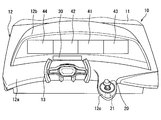
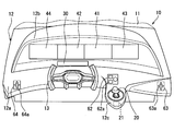
- FIG. 1 is a perspective view showing vehicle mounting positions of an operation device and a line-of-sight detection sensor in the first embodiment of the present disclosure
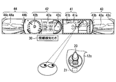
- FIG. 2 is a diagram illustrating a relationship between display contents of the display device illustrated in FIG. 1 and a user's line-of-sight direction.
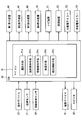
- FIG. 3 is a control block diagram illustrating the operation device, the proximity sensor, the line-of-sight detection sensor, the display device, and the like illustrated in FIG.
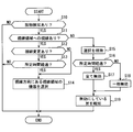
- FIG. 4 is a flowchart showing a control procedure by the microcomputer of FIG.
- FIG. 5 is a perspective view illustrating vehicle mounting positions of the operation device and the line-of-sight detection sensor in the second embodiment of the present disclosure.
- the present inventors have found that the following problems arise when the conventional technology is actually embodied. That is, a plurality of line-of-sight areas are set in advance in association with each of the devices, and after the line of sight is aligned with the line-of-sight area associated with the device to be commanded, if the line of sight is removed from the line-of-sight area, the command is canceled or the like The command with the desired content cannot be maintained, such as when the command is executed. In addition, since it is necessary to align the line of sight with the line-of-sight area again, it is troublesome.
- This disclosure is intended to provide an operation system that improves the easiness of command to a device.
- FIG. 1 is a perspective view of the front side of the vehicle 10 as viewed from inside the vehicle 10.
- a resin instrument panel 12 is installed below the front windshield 11 in the passenger compartment.
- the instrument panel 12 includes a horizontal portion 12a extending in the horizontal direction, a protruding portion 12b protruding upward from the horizontal portion 12a, and an extending portion 12c extending from the horizontal portion 12a to the vehicle rear side.
- the protrusion 12b has a shape having an opening that opens toward the vehicle rear side, and a plurality of (four in the example of FIG. 1) display devices 41, 42, 43, and 44 are arranged in the opening. ing. These display devices 41, 42, 43, and 44 are arranged in a line in the left-right direction of the vehicle 10 (left-right direction in FIG. 1).
- the display devices 41, 42, 43, and 44 are configured to include a liquid crystal panel and a backlight, and the plurality of display devices 41, 42, 43, and 44 have the same shape and size.
- the plurality of display devices 41, 42, 43, and 44 are adjacent so that the display surface of each liquid crystal panel is visually recognized continuously in the vehicle left-right direction, that is, as one display surface extending in the left-right direction. Are arranged.
- the display device arranged at the center right side is the first display device 41
- the display device arranged at the center left side is the second display device 42
- the display device arranged at the right end is the third display.
- the display device disposed at the left end of the device 43 is referred to as a fourth display device 44.
- display areas for displaying information corresponding to the operation contents of various devices are set on the liquid crystal panels of the display devices 41, 42, 43, 44.
- This display area is preset as line-of-sight areas 41a, 42a, 43a, 44a set in association with the device.
- the vehicle 10 is equipped with devices such as a navigation device 51, an air conditioner 52, a right electronic mirror 53, a left electronic mirror 54, and an audio device (not shown).
- the navigation device 51 is a device that navigates the traveling of the vehicle 10.
- the air conditioner 52 is a device that controls the air conditioning in the passenger compartment.
- the right electronic mirror 53 includes a camera that captures an object outside the vehicle, such as another vehicle or a pedestrian located on the right side of the vehicle 10, and an actuator that controls the shooting direction of the camera.
- the left electronic mirror 54 includes a camera that captures an object outside the vehicle located on the left side of the vehicle 10 and an actuator that controls the shooting direction of the camera.
- the line-of-sight area 41a of the first display device 41 information corresponding to the operation content of the navigation device 51 is displayed. For example, map information, current position information of the vehicle 10, destination position information, travel route information, and the like are displayed. Furthermore, a highlight frame is displayed in the frame area 41b which is an area other than the line-of-sight area 41a in the first display device 41.
- the frame area 41b is set in an annular shape surrounding the line-of-sight area 41a.
- the line-of-sight area 42a of the second display device 42 information corresponding to the operation content of the air conditioner 52 is displayed. For example, information such as the temperature, air volume, and air outlet of the conditioned air is displayed. Furthermore, a vehicle speed meter and a battery power remaining meter are displayed in meter areas 42b and 42c, which are areas other than the line-of-sight area 42a, of the second display device 42.
- the meter areas 42b and 42c and the line-of-sight area 42a are arranged in a line in the left-right direction of the vehicle, and the line-of-sight area 42a is arranged between the two meter areas 42b and 42c.
- the line-of-sight area 43a of the third display device 43 information corresponding to the operation content of the right-side electronic mirror 53, that is, an image taken by the camera in the direction controlled by the actuator is displayed. Furthermore, in the other areas 43b and 43c, which are areas other than the line-of-sight area 43a, of the third display device 43, an image (for example, a black image) different from the video captured by the camera is displayed.
- the line-of-sight region 41a of the first display device 41, the line-of-sight region 43a and the other region 43b of the third display device 43 are arranged in a line in the left-right direction of the vehicle, and the other region is between the two line-of-sight regions 41a and 43a. 43b is arranged. As a result, the two line-of-sight areas 41a and 43a are spaced apart from each other by a predetermined distance or more in the vehicle left-right direction.
- the line-of-sight area 44 a of the fourth display device 44 information corresponding to the operation content of the left electronic mirror 54, that is, an image taken by the camera in the direction controlled by the actuator is displayed. Further, in the fourth display device 44, in the other areas 44b and 44c, which are areas other than the line-of-sight area 44a, an image (for example, a black-painted image) different from the video captured by the camera is displayed.
- the line-of-sight area 42a of the second display device 42, the other area 44b and the line-of-sight area 44a of the fourth display device 44 are arranged in a line in the left-right direction of the vehicle, and the other area is located between the two line-of-sight areas 41a and 44a. 44b is arranged. As a result, the two line-of-sight areas 41a and 44a are spaced apart from each other by a predetermined distance or more in the vehicle left-right direction.
- the vehicle 10 is equipped with an electronic control device (ECU 90), an operation device 20, and a line-of-sight detection sensor 30 described below.
- the operation system includes an operation device 20, a plurality of display devices 41 to 44, and an ECU 90.
- the operation device 20 is manually operated by the user, and commands the operation content to the command target device selected from the plurality of devices. This selection is made by the line-of-sight detection sensor 30 and the ECU 90.
- the line-of-sight regions 41a, 42a, 43a, and 44a are set in association with each device.
- the navigation device 51 is set in association with the line-of-sight area 41 a of the first display device 41.
- An air conditioner 52 is set in association with the line-of-sight area 42 a of the second display device 42.
- the right electronic mirror 53 is set in association with the line-of-sight area 43 a of the third display device 43.
- the left electronic mirror 54 is set in association with the line-of-sight area 44 a of the fourth display device 44.
- the operation device 20 is disposed in the extending portion 12c, and is disposed at a position where the driver (user) of the vehicle 10 can reach the hand while sitting in the driver's seat.
- the handle 13 for operating the traveling direction of the vehicle 10 is arranged on the left side in the left-right direction of the vehicle, and the operation device 20 is arranged on the opposite side (right side) with respect to the handle 13. .
- the operation device 20 is arrange
- the operation device 20 is operated by the user in three directions including an x-axis direction, a y-axis direction, and a z-axis direction.
- the x-axis direction is the vehicle left-right direction
- the y-axis direction is the vehicle front-rear direction
- the z-axis direction is the up-down direction. That is, a tilting operation in the x-axis direction and the y-axis direction and a pushing operation in the z-axis direction are possible.
- the navigation device 51 is selected as the command target device.
- the map displayed in the line-of-sight area 41a of the first display device 41 is scroll-displayed in the horizontal direction or the vertical direction (in FIG. 2). See arrow).
- the icon selected from the plurality of icons displayed in the line-of-sight area 41a is switched.
- the operation device 20 is pushed in the z-axis direction, the selected icon is confirmed, and the designation associated with the icon is output to the navigation device 51.
- the navigation device 51 operates according to the command, and the operation content is displayed in the line-of-sight area 41a.
- the manual operation of the operation device 20 includes a selection operation for selecting a desired command from a plurality of commands and a confirmation operation for confirming the selected command.
- the tilting operation corresponds to the selection operation
- the push operation corresponds to the confirmation operation.
- the proximity sensor 21 is attached to the extending portion 12c of the instrument panel 12.
- the proximity sensor 21 changes the output signal as the detection target approaches.
- the microcomputer 91 of the ECU 90 detects that the user has placed his / her hand on the operation device 20 based on the change in the signal output from the proximity sensor 21.
- the microcomputer 91 at the time of executing the detection provides a “contact detection device 91c”.
- the proximity sensor 21 may output an ON signal when the detection target approaches within a predetermined range.
- the contact detection device 91c in this case detects that the user has placed his / her hand on the operation device 20 when the ON signal is acquired.
- the line-of-sight detection sensor 30 includes an infrared camera attached to a portion of the instrument panel 12 positioned in front of the driver and a microcomputer for video analysis.
- the infrared camera images the left and right eyeballs of the driver, and the microcomputer analyzes the captured image to calculate the driver's line-of-sight direction. This image analysis may be executed by a microcomputer (microcomputer 91) included in the ECU 90.
- the microcomputer 91 of the ECU 90 selects a device corresponding to the line-of-sight area in the line-of-sight direction as the instruction target device based on the user's line-of-sight direction detected by the line-of-sight detection sensor 30.
- the microcomputer 91 selecting the command target device in this way corresponds to the “selection device 91a”. For example, when the line-of-sight area in the line-of-sight direction is the line-of-sight area 41a of the first display device 41 as shown in FIG. 2, the navigation device 51 corresponding to the line-of-sight area 41a is selected by the selection device 91a as the instruction target device. Is done.
- the line-of-sight detection by the line-of-sight detection sensor 30 is enabled and the selection device 91a performs the above selection.
- the microcomputer 91 Keeps current choices.
- the microcomputer 91 that functions and maintains the selection corresponds to the “selection maintaining device 91b”.
- the microcomputer 91 limits the command from the operation device 20 when the line of sight is out of the line-of-sight area corresponding to the command target device.
- the microcomputer 91 at the time of restriction in this way corresponds to the “restriction device 91d”.
- the restriction device 91d invalidates the command by the push operation (confirmation operation) while validating the command by the tilting operation (selection operation) of the operation device 20.
- the restriction device 91d invalidates the command from the operation device 20 when the line of sight has deviated from the line-of-sight area corresponding to the instruction target device for a predetermined time or more. That is, both the selection operation and the confirmation operation are invalidated.
- the speaker 82 (notification device) outputs a warning sound, voice, or the like. For example, various states such as when the above-described selection is confirmed or when the selection is changed are notified to the user by vibration, warning sound, voice, or the like.
- the microcomputer 91 controls the operation of the vibration device 81 (notification device) and the speaker 82 (notification device) so as to notify the user of the restriction.
- the microcomputer 91 during such control corresponds to the “notification control device 91e”.
- the vibration device 81 attached to the driver's seat, the steering wheel or the like is operated, or the speaker 82 is voice-guided to the effect of the restriction.
- FIG. 4 is a flowchart showing a procedure of processing repeatedly executed by the microcomputer 91 at a predetermined calculation cycle.
- step S10 it is determined whether or not the proximity sensor 21 detects contact. If it is determined that there is contact detection, it is estimated that the user is placing his / her hand on the operation device 20, and the user proceeds to the next step S ⁇ b> 11 assuming that the user intends to command the device by the operation device 20.
- step S ⁇ b> 11 it is determined whether or not the user is looking at any of the plurality of line-of-sight areas, that is, whether or not there is a line-of-sight area in the line-of-sight direction detected by the line-of-sight detection sensor 30. Specifically, it is determined whether any of the plurality of line-of-sight areas 41a, 42a, 43a, 44a is positioned in the line-of-sight direction.
- the line-of-sight area When it is determined that there is a line of sight to the line-of-sight area, it is determined whether there is a change in the line of sight. Specifically, when the line-of-sight area where the current line-of-sight exists is different from the line-of-sight area corresponding to the currently selected device, it is determined that there is a line-of-sight change. If no device is currently selected, it is determined that there is no line-of-sight change.
- step S13 If it is determined that the line-of-sight has been changed, it is determined in subsequent step S13 whether or not the time during which the line-of-sight has been changed has exceeded a predetermined time. If it is determined in step S13 that the predetermined time or more has elapsed, or if it is determined in step S12 that the line of sight has not been changed, the process proceeds to the next step S14. In step S14, the device corresponding to the line-of-sight area in the line-of-sight direction is selected as the command target device.
- step S13 If it is determined in step S13 that the predetermined time or more has not elapsed, the process ends without executing the selection in step S14, and the process returns to step S10. If it is determined in step S11 that the user does not see any of the plurality of line-of-sight areas, the selection of the currently selected device is maintained in step S15. For example, when the eyes are moved to the front of the vehicle 10 via the front windshield 11 while keeping an eye on the line-of-sight area corresponding to the command target device, the selection of the device is maintained.
- step S16 it is determined whether or not the line-of-sight direction is at a position deviated from any of the plurality of line-of-sight areas for a predetermined time or more.
- all operations of the operation device 20 are invalidated. Specifically, the command by any of the tilting operation (selecting operation) and the pushing operation (confirming operation) is invalidated.
- step S18 some operations of the operation device 20 are invalidated. Specifically, the command by the push operation (confirmation operation) is invalidated while the command by the tilting operation (selection operation) is validated.
- step S19 at least one of the vibration device 81 and the speaker 82 is operated so as to notify the user that the command is invalidated in step S17 or step S18.
- the selection device 91a and the selection maintenance device 91b are provided.
- the selection device 91a selects a device associated with the line-of-sight regions 41a, 42a, 43a, and 44a in the line-of-sight direction as a command target device based on the line-of-sight direction of the user detected by the line-of-sight detection sensor 30.
- the selection maintaining device 91b performs the above selection even when the gaze direction is changed to a position deviated from any of the plurality of gaze regions 41a, 42a, 43a, 44a in a state where the instruction target device is selected. Let it be maintained.
- the selection is released every time the line of sight is removed from the line-of-sight area associated with the selected command target device.
- the line of sight is moved to the front of the vehicle through the front windshield 11 while keeping an eye on the line of sight area 41a.
- the selection of the navigation device 51 is maintained. Therefore, every time the line of sight is removed, it is possible to reduce the opportunity for the user to select the navigation device 51 by aligning the line of sight with the line of sight 41a.
- the operation device 20 is operated with the line of sight removed from the line of sight 41a. Can also be commanded.
- the instruction target device when the instruction target device is selected, when the line-of-sight direction changes to a position that is out of any of the plurality of line-of-sight areas 41a, 42a, 43a, 44a, a command from the operation device 20 is issued.
- a limiting device 91d for limiting is provided. According to this, when an eye is taken away from the line-of-sight areas 41a, 42a, 43a, 44a, the command by the operation device 20 is limited while the selection is maintained.
- the restriction device 91d The command is limited by Therefore, it is possible to suppress the device from operating unintentionally due to an erroneous operation.
- the restriction device 91d invalidates the command by the confirmation operation while validating the command by the selection operation of the operation device 20. According to this, even if the eyes are apart from the line-of-sight areas 41a, 42a, 43a, 44a, the selection is maintained and a command by the selection operation is possible. Therefore, for example, when information corresponding to the operation content is displayed in the line-of-sight areas 41a, 42a, 43a, and 44a, a blind operation can be performed without viewing the display, thereby improving operability. Nevertheless, since the command by the confirmation operation is invalidated, it is possible to prevent the device from operating unintentionally due to an erroneous operation.
- the selection operation and the confirmation are performed when the line-of-sight direction is at a position deviated from any of the plurality of line-of-sight areas 41a, 42a, 43a, and 44a for a predetermined time or more. Disable the command by operation.
- the user has not looked at the line-of-sight areas 41a, 42a, 43a, and 44a for a predetermined time or more, there is a high possibility that the user does not intend to operate the operation device 20 to instruct the device. Therefore, in such a case, according to the present embodiment that invalidates the command by the selection operation and the confirmation operation, it is possible to further suppress the operation of the device against the intention due to an erroneous operation.
- a notification control device 91e controls the operation of the vibration device 81 and the speaker 82 so as to notify the user that the restriction is made. According to this, it is possible to reduce the possibility that the user who has noticed that the command is restricted will be mistaken for the failure of the operation system.
- the line-of-sight areas 41a, 42a, 43a, 44a are provided in each of the devices, and are set as display areas for displaying information according to the operation content. According to this, by manually operating the operation device 20 while viewing information corresponding to the operation content displayed in the line-of-sight area, it is possible to instruct a change in the operation content.
- the navigation device 51 is selected as the instruction target device, and the map information can be scrolled by manually operating the operation device 20 while viewing the map information displayed in the line-of-sight area 41a. Therefore, even a device requiring a complicated operation content command can be easily commanded.
- the selection of which of the plurality of devices to be the command target device can be selected by just looking at the line-of-sight area corresponding to the desired device. For example, in the state of FIG. 2 in which the navigation device 51 is selected as the command target device, when the line of sight is moved to the line-of-sight area 42a of the second display device 42, the device (air conditioner 52) corresponding to the second display device 42 is commanded. Selected as target device.
- a simple command such as selection of a command target device is realized using the line-of-sight detection sensor 30, and a complicated command such as setting of operation content is realized using the operation device 20.
- a contact detection device 91c that detects that the user is touching the operation device 20 is provided, and the selection device 91a detects the line of sight of the line of sight detection sensor 30 during the period in which the contact detection is performed by the contact detection device 91c. Enable detection and execute selection. According to this, when the user does not touch the operation device 20, that is, when the user does not intend to instruct the device, it is possible to avoid the troublesomeness of selecting the device in the line-of-sight region in the line-of-sight direction.
- the line-of-sight detection sensor 30 when a line-of-sight movement to a line-of-sight area different from the line-of-sight area corresponding to the command target device is detected by the line-of-sight detection sensor 30, the line-of-sight movement continues for a predetermined time or more. If not, the selection of the command target device is maintained. According to this, since the selection is not changed if only the other line-of-sight area is viewed for a short time, the other line-of-sight area can be viewed without changing the selection of the instruction target device.
- a frame region 41b selection notification display unit for notifying that the line-of-sight region corresponding to the instruction target device is selected by the selection device 91a is provided. According to this, since it becomes easy for the user to recognize which command target device is currently selected, the ease of commanding the device can be further improved.
- each display apparatus 41, 42, 43, 44 is set as the visual line area
- the position of the operation panel described below is set in advance as line-of-sight areas 62, 63, and 64 (see FIG. 5) associated with the device.
- the first operation panel, the second operation panel, and the third operation panel are disposed below the display devices 41, 42, 43, and 44 in the instrument panel 12.
- the first operation panel is set as a line-of-sight area associated with the air conditioner 52, and includes an operation member 62a such as a switch or a dial for instructing the operation content of the air conditioner 52.
- the second operation panel is set as a line-of-sight region associated with the right electronic mirror 53, and includes an operation member 63a such as a switch for instructing the operation content of the right electronic mirror 53.
- the third operation panel is set as a line-of-sight region associated with the left electronic mirror 54, and includes an operation member 64a such as a switch for instructing the operation content of the left electronic mirror 54.
- Each device operates based on the operation of the operation members 62a, 63a, and 64a.
- the device selected by the selection device 91a operates based on the operation of the operation device 20.
- the configuration shown in FIG. 3 is provided in the same manner as in the first embodiment, and the processing in FIG. 4 is executed in the same manner as in the first embodiment. As described above, even when the line-of-sight areas 41a, 42a, 43a, and 44a are not display areas of the display device, the operation system according to the present disclosure can be applied.
- the proximity sensor 21 shown in FIGS. 1 and 2 may be either a non-contact type or a contact type. Further, a sensor that detects a change in magnetic field or a sensor that detects a change in capacitance may be used.
- the attachment position of the proximity sensor 21 is not limited to the extending portion 12c, and the proximity sensor 21 may be attached to the operation device 20, for example.
- the contact detection device 91c may detect that it is in contact. For example, based on the fact that the operation device 20 is tilted or pushed, the contact detection device 91c may detect that the user has placed his / her hand on the operation device 20.
- the command by the confirmation operation is invalidated while the command by the selection operation of the operation device 20 is validated.
- the command by the confirmation operation may be validated while the command by the selection operation of the operation device 20 is invalidated.
- a selection operation is performed while viewing the line-of-sight areas 41a, 42a, 43a, and 44a with a red signal, and then, when the display changes to a blue signal, the confirmation operation is performed by keeping an eye on the line-of-sight areas 41a, 42a, 43a, and 44a Useful when doing.
- this type of confirmation operation include turning on / off various switches, setting the temperature of the air conditioner 52, and the like.
- display devices 41, 42, 43, 44 are arranged in the opening of the instrument panel 12.
- this indication is not limited to such arrangement, for example, a display device may be arranged on a dashboard.
- a plurality of display devices 41, 42, 43, 44 are arranged in a line in the vehicle left-right direction.
- the present disclosure is not limited to such an arrangement.
- a plurality of display devices may be arranged at positions shifted in the vertical direction.
- the operation device 20 is arranged on the instrument panel 12.
- the present disclosure is not limited to such an arrangement.
- the operation device 20 may be arranged on the handle 13.
- the device and / or function provided by the ECU 90 can be provided by software recorded in a substantial storage medium and a computer that executes the software, only software, only hardware, or a combination thereof.
- the controller can be provided by a circuit that is hardware, it can be provided by a digital circuit including a number of logic circuits, or an analog circuit.
- each section is expressed as S10, for example.
- each section can be divided into a plurality of subsections, while a plurality of sections can be combined into one section.
- each section configured in this manner can be referred to as a device, module, or means.
Abstract
L'invention concerne un système d'exploitation qui comprend : un dispositif d'opération (20) manuellement opéré par un utilisateur et qui utilise un contenu d'opération pour commander un dispositif à commander choisi parmi une pluralité de dispositifs (51, 52, 53, 54) ; un dispositif de sélection (91a) qui utilise une pluralité de régions de ligne de visée (41a, 42a, 43a, 44a, 62, 63, 64) associées à chacun des dispositifs et définies pour ceux-ci et la ligne de visée de l'utilisateur détectée par un capteur de détection de ligne de visée (30) en tant que base pour sélectionner un dispositif associé à une région de ligne de visée dans la ligne de visée en guise de dispositif à commander ; et un dispositif de maintien de sélection (91b) qui, lorsque le dispositif à commander est sélectionné, maintient l'état sélectionné du dispositif à commander même lorsque la ligne de visée change vers une position à l'extérieur de la totalité de la pluralité de régions de ligne de visée.
Priority Applications (3)
| Application Number | Priority Date | Filing Date | Title |
|---|---|---|---|
| US15/554,844 US10317996B2 (en) | 2015-03-25 | 2016-03-04 | Operation system |
| CN201680016796.7A CN107428298A (zh) | 2015-03-25 | 2016-03-04 | 操作系统 |
| DE112016001374.4T DE112016001374T5 (de) | 2015-03-25 | 2016-03-04 | Betätigungssystem |
Applications Claiming Priority (2)
| Application Number | Priority Date | Filing Date | Title |
|---|---|---|---|
| JP2015-063292 | 2015-03-25 | ||
| JP2015063292A JP6406088B2 (ja) | 2015-03-25 | 2015-03-25 | 操作システム |
Publications (1)
| Publication Number | Publication Date |
|---|---|
| WO2016152047A1 true WO2016152047A1 (fr) | 2016-09-29 |
Family
ID=56977111
Family Applications (1)
| Application Number | Title | Priority Date | Filing Date |
|---|---|---|---|
| PCT/JP2016/001199 WO2016152047A1 (fr) | 2015-03-25 | 2016-03-04 | Système d'exploitation |
Country Status (5)
| Country | Link |
|---|---|
| US (1) | US10317996B2 (fr) |
| JP (1) | JP6406088B2 (fr) |
| CN (1) | CN107428298A (fr) |
| DE (1) | DE112016001374T5 (fr) |
| WO (1) | WO2016152047A1 (fr) |
Cited By (2)
| Publication number | Priority date | Publication date | Assignee | Title |
|---|---|---|---|---|
| WO2019053200A1 (fr) * | 2017-09-18 | 2019-03-21 | Bayerische Motoren Werke Aktiengesellschaft | Procédé d'émission d'informations relatives à un objet d'un moyen de locomotion, système et véhicule automobile |
| US20190212819A1 (en) * | 2018-01-05 | 2019-07-11 | Lg Electronics Inc. | Input output device and vehicle comprising the same |
Families Citing this family (4)
| Publication number | Priority date | Publication date | Assignee | Title |
|---|---|---|---|---|
| JP7165864B2 (ja) * | 2018-09-28 | 2022-11-07 | パナソニックIpマネジメント株式会社 | 機器制御システム、移動体、機器制御方法及びプログラム |
| JP7167901B2 (ja) | 2019-11-08 | 2022-11-09 | 株式会社デンソー | 表示装置 |
| DE102019132759A1 (de) * | 2019-12-03 | 2021-06-10 | Valeo Schalter Und Sensoren Gmbh | Verfahren zum ferngesteuerten Führen eines Kraftfahrzeugs mit einem Teleoperator,Computerprogrammprodukt und Teleoperationsführungssystem |
| CN112896074A (zh) * | 2019-12-04 | 2021-06-04 | 纳恩博(常州)科技有限公司 | 一种控制方法及装置、车辆、计算机可读存储介质 |
Citations (4)
| Publication number | Priority date | Publication date | Assignee | Title |
|---|---|---|---|---|
| JPH07159316A (ja) * | 1993-12-06 | 1995-06-23 | Nissan Motor Co Ltd | 車両用視線方向計測装置 |
| JP2010012995A (ja) * | 2008-07-04 | 2010-01-21 | Tokai Rika Co Ltd | 照明装置 |
| JP2012006552A (ja) * | 2010-06-28 | 2012-01-12 | Honda Motor Co Ltd | 車載機器操作装置 |
| JP2012210874A (ja) * | 2011-03-31 | 2012-11-01 | Honda Motor Co Ltd | 車載入力装置 |
Family Cites Families (16)
| Publication number | Priority date | Publication date | Assignee | Title |
|---|---|---|---|---|
| US7742857B2 (en) * | 2005-12-07 | 2010-06-22 | Mazda Motor Corporation | Automotive information display system |
| EP2000889B1 (fr) * | 2006-03-15 | 2018-06-27 | Omron Corporation | Dispositif et procédé de surveillance, dispositif et procédé de commande, et programme |
| DE102008048825A1 (de) * | 2008-09-22 | 2010-03-25 | Volkswagen Ag | Anzeige- und Bediensystem in einem Kraftfahrzeug mit nutzerbeeinflussbarer Darstellung von Anzeigeobjekten sowie Verfahren zum Betreiben eines solchen Anzeige- und Bediensystems |
| US9108513B2 (en) * | 2008-11-10 | 2015-08-18 | Volkswagen Ag | Viewing direction and acoustic command based operating device for a motor vehicle |
| JP2010215194A (ja) * | 2009-03-19 | 2010-09-30 | Hyundai Motor Co Ltd | 車載機器の操作装置 |
| JP4837762B2 (ja) * | 2009-06-18 | 2011-12-14 | 本田技研工業株式会社 | 車載機器操作装置 |
| US20120198353A1 (en) * | 2011-01-28 | 2012-08-02 | Microsoft Corporation | Transferring data using a physical gesture |
| US20120215403A1 (en) * | 2011-02-20 | 2012-08-23 | General Motors Llc | Method of monitoring a vehicle driver |
| JP5554879B2 (ja) * | 2011-06-20 | 2014-07-23 | 本田技研工業株式会社 | 車載機器操作装置及び報知装置 |
| JP5367037B2 (ja) * | 2011-09-26 | 2013-12-11 | 本田技研工業株式会社 | 顔向き検出装置 |
| JP2014174598A (ja) | 2013-03-06 | 2014-09-22 | Denso Corp | 車両入力装置 |
| JP6015547B2 (ja) | 2013-05-09 | 2016-10-26 | 株式会社デンソー | 視線入力装置 |
| JP6033804B2 (ja) * | 2014-02-18 | 2016-11-30 | 本田技研工業株式会社 | 車載機器操作装置 |
| WO2016045911A1 (fr) * | 2014-09-25 | 2016-03-31 | Philips Lighting Holding B.V. | Commande d'éclairage |
| JP6464869B2 (ja) | 2015-03-25 | 2019-02-06 | 株式会社デンソー | 操作システム |
| JP6477123B2 (ja) | 2015-03-25 | 2019-03-06 | 株式会社デンソー | 操作システム |
-
2015
- 2015-03-25 JP JP2015063292A patent/JP6406088B2/ja not_active Expired - Fee Related
-
2016
- 2016-03-04 WO PCT/JP2016/001199 patent/WO2016152047A1/fr active Application Filing
- 2016-03-04 US US15/554,844 patent/US10317996B2/en not_active Expired - Fee Related
- 2016-03-04 CN CN201680016796.7A patent/CN107428298A/zh active Pending
- 2016-03-04 DE DE112016001374.4T patent/DE112016001374T5/de not_active Withdrawn
Patent Citations (4)
| Publication number | Priority date | Publication date | Assignee | Title |
|---|---|---|---|---|
| JPH07159316A (ja) * | 1993-12-06 | 1995-06-23 | Nissan Motor Co Ltd | 車両用視線方向計測装置 |
| JP2010012995A (ja) * | 2008-07-04 | 2010-01-21 | Tokai Rika Co Ltd | 照明装置 |
| JP2012006552A (ja) * | 2010-06-28 | 2012-01-12 | Honda Motor Co Ltd | 車載機器操作装置 |
| JP2012210874A (ja) * | 2011-03-31 | 2012-11-01 | Honda Motor Co Ltd | 車載入力装置 |
Cited By (3)
| Publication number | Priority date | Publication date | Assignee | Title |
|---|---|---|---|---|
| WO2019053200A1 (fr) * | 2017-09-18 | 2019-03-21 | Bayerische Motoren Werke Aktiengesellschaft | Procédé d'émission d'informations relatives à un objet d'un moyen de locomotion, système et véhicule automobile |
| US20190212819A1 (en) * | 2018-01-05 | 2019-07-11 | Lg Electronics Inc. | Input output device and vehicle comprising the same |
| US10732715B2 (en) * | 2018-01-05 | 2020-08-04 | Lg Electronics Inc. | Input output device and vehicle comprising the same |
Also Published As
| Publication number | Publication date |
|---|---|
| US20180046246A1 (en) | 2018-02-15 |
| JP2016182857A (ja) | 2016-10-20 |
| CN107428298A (zh) | 2017-12-01 |
| DE112016001374T5 (de) | 2017-12-14 |
| JP6406088B2 (ja) | 2018-10-17 |
| US10317996B2 (en) | 2019-06-11 |
Similar Documents
| Publication | Publication Date | Title |
|---|---|---|
| WO2016152047A1 (fr) | Système d'exploitation | |
| JP6464869B2 (ja) | 操作システム | |
| JP6381826B2 (ja) | 車両情報表示制御装置 | |
| JP4758087B2 (ja) | 表示装置 | |
| WO2016152044A1 (fr) | Système de commande | |
| WO2013157492A1 (fr) | Dispositif d'affichage pour fonctionnement dans une voiture | |
| US20180208212A1 (en) | User Interface Device for Selecting an Operating Mode for an Automated Drive | |
| US20150042803A1 (en) | Motor vehicle comprising an electronic rear-view mirror | |
| JP2010215194A (ja) | 車載機器の操作装置 | |
| JP5456899B2 (ja) | 車両用操作装置 | |
| JP2007310496A (ja) | タッチ操作入力装置 | |
| JP2006264615A (ja) | 車両用表示装置 | |
| JP6156052B2 (ja) | 車両用情報処理装置 | |
| JP2008195141A (ja) | 車載機器の操作支援装置、操作支援方法 | |
| EP3543061B1 (fr) | Afficheur pour véhicule | |
| JP6375715B2 (ja) | 視線入力装置 | |
| JP5903319B2 (ja) | 車両用表示装置 | |
| JP2012096670A (ja) | 入力装置及び入力方法 | |
| EP3674140A1 (fr) | Système de rétroviseur électronique | |
| JP6520817B2 (ja) | 車両用操作装置 | |
| JP2016149094A (ja) | 車両用情報処理装置 | |
| JP2005313722A (ja) | 車載機器の操作表示装置及びその操作表示方法 | |
| JP5146691B2 (ja) | 遠隔操作装置 | |
| JP2014219682A (ja) | 表示制御システム及びプログラム | |
| JP6298599B2 (ja) | 車両用表示装置 |
Legal Events
| Date | Code | Title | Description |
|---|---|---|---|
| 121 | Ep: the epo has been informed by wipo that ep was designated in this application |
Ref document number: 16767957 Country of ref document: EP Kind code of ref document: A1 |
|
| WWE | Wipo information: entry into national phase |
Ref document number: 15554844 Country of ref document: US |
|
| WWE | Wipo information: entry into national phase |
Ref document number: 112016001374 Country of ref document: DE |
|
| 122 | Ep: pct application non-entry in european phase |
Ref document number: 16767957 Country of ref document: EP Kind code of ref document: A1 |