WO2016152047A1 - Operation system - Google Patents
Operation system Download PDFInfo
- Publication number
- WO2016152047A1 WO2016152047A1 PCT/JP2016/001199 JP2016001199W WO2016152047A1 WO 2016152047 A1 WO2016152047 A1 WO 2016152047A1 JP 2016001199 W JP2016001199 W JP 2016001199W WO 2016152047 A1 WO2016152047 A1 WO 2016152047A1
- Authority
- WO
- WIPO (PCT)
- Prior art keywords
- line
- sight
- command
- selection
- user
- Prior art date
Links
- 238000001514 detection method Methods 0.000 claims abstract description 33
- 238000012790 confirmation Methods 0.000 claims description 16
- 238000012423 maintenance Methods 0.000 abstract description 2
- 230000008859 change Effects 0.000 description 7
- 210000001508 eye Anatomy 0.000 description 7
- 238000000034 method Methods 0.000 description 6
- 125000002066 L-histidyl group Chemical group [H]N1C([H])=NC(C([H])([H])[C@](C(=O)[*])([H])N([H])[H])=C1[H] 0.000 description 4
- 230000008569 process Effects 0.000 description 4
- 239000004973 liquid crystal related substance Substances 0.000 description 3
- 238000012986 modification Methods 0.000 description 3
- 230000004048 modification Effects 0.000 description 3
- 238000013459 approach Methods 0.000 description 2
- 238000010586 diagram Methods 0.000 description 2
- 238000012545 processing Methods 0.000 description 2
- 238000004378 air conditioning Methods 0.000 description 1
- 238000004458 analytical method Methods 0.000 description 1
- 210000005252 bulbus oculi Anatomy 0.000 description 1
- 238000004364 calculation method Methods 0.000 description 1
- 230000001143 conditioned effect Effects 0.000 description 1
- 238000011161 development Methods 0.000 description 1
- 230000000694 effects Effects 0.000 description 1
- 238000005516 engineering process Methods 0.000 description 1
- 238000010191 image analysis Methods 0.000 description 1
- 239000011347 resin Substances 0.000 description 1
- 229920005989 resin Polymers 0.000 description 1
- 230000000007 visual effect Effects 0.000 description 1
Images
Classifications
-
- G—PHYSICS
- G06—COMPUTING; CALCULATING OR COUNTING
- G06F—ELECTRIC DIGITAL DATA PROCESSING
- G06F3/00—Input arrangements for transferring data to be processed into a form capable of being handled by the computer; Output arrangements for transferring data from processing unit to output unit, e.g. interface arrangements
- G06F3/01—Input arrangements or combined input and output arrangements for interaction between user and computer
- G06F3/011—Arrangements for interaction with the human body, e.g. for user immersion in virtual reality
- G06F3/013—Eye tracking input arrangements
-
- B—PERFORMING OPERATIONS; TRANSPORTING
- B60—VEHICLES IN GENERAL
- B60K—ARRANGEMENT OR MOUNTING OF PROPULSION UNITS OR OF TRANSMISSIONS IN VEHICLES; ARRANGEMENT OR MOUNTING OF PLURAL DIVERSE PRIME-MOVERS IN VEHICLES; AUXILIARY DRIVES FOR VEHICLES; INSTRUMENTATION OR DASHBOARDS FOR VEHICLES; ARRANGEMENTS IN CONNECTION WITH COOLING, AIR INTAKE, GAS EXHAUST OR FUEL SUPPLY OF PROPULSION UNITS IN VEHICLES
- B60K35/00—Arrangement of adaptations of instruments
-
- B60K35/10—
-
- G—PHYSICS
- G06—COMPUTING; CALCULATING OR COUNTING
- G06F—ELECTRIC DIGITAL DATA PROCESSING
- G06F3/00—Input arrangements for transferring data to be processed into a form capable of being handled by the computer; Output arrangements for transferring data from processing unit to output unit, e.g. interface arrangements
- G06F3/14—Digital output to display device ; Cooperation and interconnection of the display device with other functional units
- G06F3/1423—Digital output to display device ; Cooperation and interconnection of the display device with other functional units controlling a plurality of local displays, e.g. CRT and flat panel display
-
- B60K2360/146—
-
- B60K2360/1464—
-
- B60K2360/149—
-
- B60K2360/21—
-
- B60K35/81—
-
- G—PHYSICS
- G06—COMPUTING; CALCULATING OR COUNTING
- G06F—ELECTRIC DIGITAL DATA PROCESSING
- G06F3/00—Input arrangements for transferring data to be processed into a form capable of being handled by the computer; Output arrangements for transferring data from processing unit to output unit, e.g. interface arrangements
- G06F3/01—Input arrangements or combined input and output arrangements for interaction between user and computer
- G06F3/048—Interaction techniques based on graphical user interfaces [GUI]
- G06F3/0481—Interaction techniques based on graphical user interfaces [GUI] based on specific properties of the displayed interaction object or a metaphor-based environment, e.g. interaction with desktop elements like windows or icons, or assisted by a cursor's changing behaviour or appearance
- G06F3/0482—Interaction with lists of selectable items, e.g. menus
Definitions
- This disclosure relates to an operation system in which an operation device and line-of-sight detection are linked.
- Patent Documents 1 and 2 In recent years, development of a gaze detection sensor that detects the gaze direction of a user has progressed (see Patent Documents 1 and 2). According to this, when it is desired to operate the device with the desired content, the above content can be commanded to the device simply by moving the line of sight.
- This disclosure is intended to provide an operation system that improves the easiness of command to a device.
- an operation system is manually operated by a user, and an operation device that instructs operation content to a command target device selected from among a plurality of devices, and a plurality of devices that are set in association with each of the devices.
- a selection device that selects the device associated with the line-of-sight region in the line-of-sight direction as the command target device based on the line-of-sight region and the user's line-of-sight direction detected by the line-of-sight detection sensor;
- a selection maintaining device that maintains the selected state of the command target device even when the line-of-sight direction changes to a position deviated from any of the plurality of line-of-sight regions in the selected state.
- this operation system it is possible to avoid that the selection is canceled every time the line of sight is removed from the line-of-sight area associated with the selected command target device. Accordingly, it is possible to reduce the opportunity for the trouble of adjusting the line of sight again to the line-of-sight area every time the line of sight is removed, and it is also possible to operate the operation device and give a command with the line of sight removed. As described above, according to the above-described invention, it is possible to improve the easiness of command to the device.
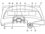
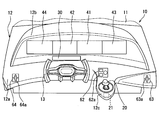
- FIG. 1 is a perspective view showing vehicle mounting positions of an operation device and a line-of-sight detection sensor in the first embodiment of the present disclosure
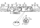
- FIG. 2 is a diagram illustrating a relationship between display contents of the display device illustrated in FIG. 1 and a user's line-of-sight direction.
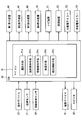
- FIG. 3 is a control block diagram illustrating the operation device, the proximity sensor, the line-of-sight detection sensor, the display device, and the like illustrated in FIG.
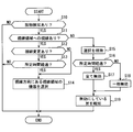
- FIG. 4 is a flowchart showing a control procedure by the microcomputer of FIG.
- FIG. 5 is a perspective view illustrating vehicle mounting positions of the operation device and the line-of-sight detection sensor in the second embodiment of the present disclosure.
- the present inventors have found that the following problems arise when the conventional technology is actually embodied. That is, a plurality of line-of-sight areas are set in advance in association with each of the devices, and after the line of sight is aligned with the line-of-sight area associated with the device to be commanded, if the line of sight is removed from the line-of-sight area, the command is canceled or the like The command with the desired content cannot be maintained, such as when the command is executed. In addition, since it is necessary to align the line of sight with the line-of-sight area again, it is troublesome.
- This disclosure is intended to provide an operation system that improves the easiness of command to a device.
- FIG. 1 is a perspective view of the front side of the vehicle 10 as viewed from inside the vehicle 10.
- a resin instrument panel 12 is installed below the front windshield 11 in the passenger compartment.
- the instrument panel 12 includes a horizontal portion 12a extending in the horizontal direction, a protruding portion 12b protruding upward from the horizontal portion 12a, and an extending portion 12c extending from the horizontal portion 12a to the vehicle rear side.
- the protrusion 12b has a shape having an opening that opens toward the vehicle rear side, and a plurality of (four in the example of FIG. 1) display devices 41, 42, 43, and 44 are arranged in the opening. ing. These display devices 41, 42, 43, and 44 are arranged in a line in the left-right direction of the vehicle 10 (left-right direction in FIG. 1).
- the display devices 41, 42, 43, and 44 are configured to include a liquid crystal panel and a backlight, and the plurality of display devices 41, 42, 43, and 44 have the same shape and size.
- the plurality of display devices 41, 42, 43, and 44 are adjacent so that the display surface of each liquid crystal panel is visually recognized continuously in the vehicle left-right direction, that is, as one display surface extending in the left-right direction. Are arranged.
- the display device arranged at the center right side is the first display device 41
- the display device arranged at the center left side is the second display device 42
- the display device arranged at the right end is the third display.
- the display device disposed at the left end of the device 43 is referred to as a fourth display device 44.
- display areas for displaying information corresponding to the operation contents of various devices are set on the liquid crystal panels of the display devices 41, 42, 43, 44.
- This display area is preset as line-of-sight areas 41a, 42a, 43a, 44a set in association with the device.
- the vehicle 10 is equipped with devices such as a navigation device 51, an air conditioner 52, a right electronic mirror 53, a left electronic mirror 54, and an audio device (not shown).
- the navigation device 51 is a device that navigates the traveling of the vehicle 10.
- the air conditioner 52 is a device that controls the air conditioning in the passenger compartment.
- the right electronic mirror 53 includes a camera that captures an object outside the vehicle, such as another vehicle or a pedestrian located on the right side of the vehicle 10, and an actuator that controls the shooting direction of the camera.
- the left electronic mirror 54 includes a camera that captures an object outside the vehicle located on the left side of the vehicle 10 and an actuator that controls the shooting direction of the camera.
- the line-of-sight area 41a of the first display device 41 information corresponding to the operation content of the navigation device 51 is displayed. For example, map information, current position information of the vehicle 10, destination position information, travel route information, and the like are displayed. Furthermore, a highlight frame is displayed in the frame area 41b which is an area other than the line-of-sight area 41a in the first display device 41.
- the frame area 41b is set in an annular shape surrounding the line-of-sight area 41a.
- the line-of-sight area 42a of the second display device 42 information corresponding to the operation content of the air conditioner 52 is displayed. For example, information such as the temperature, air volume, and air outlet of the conditioned air is displayed. Furthermore, a vehicle speed meter and a battery power remaining meter are displayed in meter areas 42b and 42c, which are areas other than the line-of-sight area 42a, of the second display device 42.
- the meter areas 42b and 42c and the line-of-sight area 42a are arranged in a line in the left-right direction of the vehicle, and the line-of-sight area 42a is arranged between the two meter areas 42b and 42c.
- the line-of-sight area 43a of the third display device 43 information corresponding to the operation content of the right-side electronic mirror 53, that is, an image taken by the camera in the direction controlled by the actuator is displayed. Furthermore, in the other areas 43b and 43c, which are areas other than the line-of-sight area 43a, of the third display device 43, an image (for example, a black image) different from the video captured by the camera is displayed.
- the line-of-sight region 41a of the first display device 41, the line-of-sight region 43a and the other region 43b of the third display device 43 are arranged in a line in the left-right direction of the vehicle, and the other region is between the two line-of-sight regions 41a and 43a. 43b is arranged. As a result, the two line-of-sight areas 41a and 43a are spaced apart from each other by a predetermined distance or more in the vehicle left-right direction.
- the line-of-sight area 44 a of the fourth display device 44 information corresponding to the operation content of the left electronic mirror 54, that is, an image taken by the camera in the direction controlled by the actuator is displayed. Further, in the fourth display device 44, in the other areas 44b and 44c, which are areas other than the line-of-sight area 44a, an image (for example, a black-painted image) different from the video captured by the camera is displayed.
- the line-of-sight area 42a of the second display device 42, the other area 44b and the line-of-sight area 44a of the fourth display device 44 are arranged in a line in the left-right direction of the vehicle, and the other area is located between the two line-of-sight areas 41a and 44a. 44b is arranged. As a result, the two line-of-sight areas 41a and 44a are spaced apart from each other by a predetermined distance or more in the vehicle left-right direction.
- the vehicle 10 is equipped with an electronic control device (ECU 90), an operation device 20, and a line-of-sight detection sensor 30 described below.
- the operation system includes an operation device 20, a plurality of display devices 41 to 44, and an ECU 90.
- the operation device 20 is manually operated by the user, and commands the operation content to the command target device selected from the plurality of devices. This selection is made by the line-of-sight detection sensor 30 and the ECU 90.
- the line-of-sight regions 41a, 42a, 43a, and 44a are set in association with each device.
- the navigation device 51 is set in association with the line-of-sight area 41 a of the first display device 41.
- An air conditioner 52 is set in association with the line-of-sight area 42 a of the second display device 42.
- the right electronic mirror 53 is set in association with the line-of-sight area 43 a of the third display device 43.
- the left electronic mirror 54 is set in association with the line-of-sight area 44 a of the fourth display device 44.
- the operation device 20 is disposed in the extending portion 12c, and is disposed at a position where the driver (user) of the vehicle 10 can reach the hand while sitting in the driver's seat.
- the handle 13 for operating the traveling direction of the vehicle 10 is arranged on the left side in the left-right direction of the vehicle, and the operation device 20 is arranged on the opposite side (right side) with respect to the handle 13. .
- the operation device 20 is arrange
- the operation device 20 is operated by the user in three directions including an x-axis direction, a y-axis direction, and a z-axis direction.
- the x-axis direction is the vehicle left-right direction
- the y-axis direction is the vehicle front-rear direction
- the z-axis direction is the up-down direction. That is, a tilting operation in the x-axis direction and the y-axis direction and a pushing operation in the z-axis direction are possible.
- the navigation device 51 is selected as the command target device.
- the map displayed in the line-of-sight area 41a of the first display device 41 is scroll-displayed in the horizontal direction or the vertical direction (in FIG. 2). See arrow).
- the icon selected from the plurality of icons displayed in the line-of-sight area 41a is switched.
- the operation device 20 is pushed in the z-axis direction, the selected icon is confirmed, and the designation associated with the icon is output to the navigation device 51.
- the navigation device 51 operates according to the command, and the operation content is displayed in the line-of-sight area 41a.
- the manual operation of the operation device 20 includes a selection operation for selecting a desired command from a plurality of commands and a confirmation operation for confirming the selected command.
- the tilting operation corresponds to the selection operation
- the push operation corresponds to the confirmation operation.
- the proximity sensor 21 is attached to the extending portion 12c of the instrument panel 12.
- the proximity sensor 21 changes the output signal as the detection target approaches.
- the microcomputer 91 of the ECU 90 detects that the user has placed his / her hand on the operation device 20 based on the change in the signal output from the proximity sensor 21.
- the microcomputer 91 at the time of executing the detection provides a “contact detection device 91c”.
- the proximity sensor 21 may output an ON signal when the detection target approaches within a predetermined range.
- the contact detection device 91c in this case detects that the user has placed his / her hand on the operation device 20 when the ON signal is acquired.
- the line-of-sight detection sensor 30 includes an infrared camera attached to a portion of the instrument panel 12 positioned in front of the driver and a microcomputer for video analysis.
- the infrared camera images the left and right eyeballs of the driver, and the microcomputer analyzes the captured image to calculate the driver's line-of-sight direction. This image analysis may be executed by a microcomputer (microcomputer 91) included in the ECU 90.
- the microcomputer 91 of the ECU 90 selects a device corresponding to the line-of-sight area in the line-of-sight direction as the instruction target device based on the user's line-of-sight direction detected by the line-of-sight detection sensor 30.
- the microcomputer 91 selecting the command target device in this way corresponds to the “selection device 91a”. For example, when the line-of-sight area in the line-of-sight direction is the line-of-sight area 41a of the first display device 41 as shown in FIG. 2, the navigation device 51 corresponding to the line-of-sight area 41a is selected by the selection device 91a as the instruction target device. Is done.
- the line-of-sight detection by the line-of-sight detection sensor 30 is enabled and the selection device 91a performs the above selection.
- the microcomputer 91 Keeps current choices.
- the microcomputer 91 that functions and maintains the selection corresponds to the “selection maintaining device 91b”.
- the microcomputer 91 limits the command from the operation device 20 when the line of sight is out of the line-of-sight area corresponding to the command target device.
- the microcomputer 91 at the time of restriction in this way corresponds to the “restriction device 91d”.
- the restriction device 91d invalidates the command by the push operation (confirmation operation) while validating the command by the tilting operation (selection operation) of the operation device 20.
- the restriction device 91d invalidates the command from the operation device 20 when the line of sight has deviated from the line-of-sight area corresponding to the instruction target device for a predetermined time or more. That is, both the selection operation and the confirmation operation are invalidated.
- the speaker 82 (notification device) outputs a warning sound, voice, or the like. For example, various states such as when the above-described selection is confirmed or when the selection is changed are notified to the user by vibration, warning sound, voice, or the like.
- the microcomputer 91 controls the operation of the vibration device 81 (notification device) and the speaker 82 (notification device) so as to notify the user of the restriction.
- the microcomputer 91 during such control corresponds to the “notification control device 91e”.
- the vibration device 81 attached to the driver's seat, the steering wheel or the like is operated, or the speaker 82 is voice-guided to the effect of the restriction.
- FIG. 4 is a flowchart showing a procedure of processing repeatedly executed by the microcomputer 91 at a predetermined calculation cycle.
- step S10 it is determined whether or not the proximity sensor 21 detects contact. If it is determined that there is contact detection, it is estimated that the user is placing his / her hand on the operation device 20, and the user proceeds to the next step S ⁇ b> 11 assuming that the user intends to command the device by the operation device 20.
- step S ⁇ b> 11 it is determined whether or not the user is looking at any of the plurality of line-of-sight areas, that is, whether or not there is a line-of-sight area in the line-of-sight direction detected by the line-of-sight detection sensor 30. Specifically, it is determined whether any of the plurality of line-of-sight areas 41a, 42a, 43a, 44a is positioned in the line-of-sight direction.
- the line-of-sight area When it is determined that there is a line of sight to the line-of-sight area, it is determined whether there is a change in the line of sight. Specifically, when the line-of-sight area where the current line-of-sight exists is different from the line-of-sight area corresponding to the currently selected device, it is determined that there is a line-of-sight change. If no device is currently selected, it is determined that there is no line-of-sight change.
- step S13 If it is determined that the line-of-sight has been changed, it is determined in subsequent step S13 whether or not the time during which the line-of-sight has been changed has exceeded a predetermined time. If it is determined in step S13 that the predetermined time or more has elapsed, or if it is determined in step S12 that the line of sight has not been changed, the process proceeds to the next step S14. In step S14, the device corresponding to the line-of-sight area in the line-of-sight direction is selected as the command target device.
- step S13 If it is determined in step S13 that the predetermined time or more has not elapsed, the process ends without executing the selection in step S14, and the process returns to step S10. If it is determined in step S11 that the user does not see any of the plurality of line-of-sight areas, the selection of the currently selected device is maintained in step S15. For example, when the eyes are moved to the front of the vehicle 10 via the front windshield 11 while keeping an eye on the line-of-sight area corresponding to the command target device, the selection of the device is maintained.
- step S16 it is determined whether or not the line-of-sight direction is at a position deviated from any of the plurality of line-of-sight areas for a predetermined time or more.
- all operations of the operation device 20 are invalidated. Specifically, the command by any of the tilting operation (selecting operation) and the pushing operation (confirming operation) is invalidated.
- step S18 some operations of the operation device 20 are invalidated. Specifically, the command by the push operation (confirmation operation) is invalidated while the command by the tilting operation (selection operation) is validated.
- step S19 at least one of the vibration device 81 and the speaker 82 is operated so as to notify the user that the command is invalidated in step S17 or step S18.
- the selection device 91a and the selection maintenance device 91b are provided.
- the selection device 91a selects a device associated with the line-of-sight regions 41a, 42a, 43a, and 44a in the line-of-sight direction as a command target device based on the line-of-sight direction of the user detected by the line-of-sight detection sensor 30.
- the selection maintaining device 91b performs the above selection even when the gaze direction is changed to a position deviated from any of the plurality of gaze regions 41a, 42a, 43a, 44a in a state where the instruction target device is selected. Let it be maintained.
- the selection is released every time the line of sight is removed from the line-of-sight area associated with the selected command target device.
- the line of sight is moved to the front of the vehicle through the front windshield 11 while keeping an eye on the line of sight area 41a.
- the selection of the navigation device 51 is maintained. Therefore, every time the line of sight is removed, it is possible to reduce the opportunity for the user to select the navigation device 51 by aligning the line of sight with the line of sight 41a.
- the operation device 20 is operated with the line of sight removed from the line of sight 41a. Can also be commanded.
- the instruction target device when the instruction target device is selected, when the line-of-sight direction changes to a position that is out of any of the plurality of line-of-sight areas 41a, 42a, 43a, 44a, a command from the operation device 20 is issued.
- a limiting device 91d for limiting is provided. According to this, when an eye is taken away from the line-of-sight areas 41a, 42a, 43a, 44a, the command by the operation device 20 is limited while the selection is maintained.
- the restriction device 91d The command is limited by Therefore, it is possible to suppress the device from operating unintentionally due to an erroneous operation.
- the restriction device 91d invalidates the command by the confirmation operation while validating the command by the selection operation of the operation device 20. According to this, even if the eyes are apart from the line-of-sight areas 41a, 42a, 43a, 44a, the selection is maintained and a command by the selection operation is possible. Therefore, for example, when information corresponding to the operation content is displayed in the line-of-sight areas 41a, 42a, 43a, and 44a, a blind operation can be performed without viewing the display, thereby improving operability. Nevertheless, since the command by the confirmation operation is invalidated, it is possible to prevent the device from operating unintentionally due to an erroneous operation.
- the selection operation and the confirmation are performed when the line-of-sight direction is at a position deviated from any of the plurality of line-of-sight areas 41a, 42a, 43a, and 44a for a predetermined time or more. Disable the command by operation.
- the user has not looked at the line-of-sight areas 41a, 42a, 43a, and 44a for a predetermined time or more, there is a high possibility that the user does not intend to operate the operation device 20 to instruct the device. Therefore, in such a case, according to the present embodiment that invalidates the command by the selection operation and the confirmation operation, it is possible to further suppress the operation of the device against the intention due to an erroneous operation.
- a notification control device 91e controls the operation of the vibration device 81 and the speaker 82 so as to notify the user that the restriction is made. According to this, it is possible to reduce the possibility that the user who has noticed that the command is restricted will be mistaken for the failure of the operation system.
- the line-of-sight areas 41a, 42a, 43a, 44a are provided in each of the devices, and are set as display areas for displaying information according to the operation content. According to this, by manually operating the operation device 20 while viewing information corresponding to the operation content displayed in the line-of-sight area, it is possible to instruct a change in the operation content.
- the navigation device 51 is selected as the instruction target device, and the map information can be scrolled by manually operating the operation device 20 while viewing the map information displayed in the line-of-sight area 41a. Therefore, even a device requiring a complicated operation content command can be easily commanded.
- the selection of which of the plurality of devices to be the command target device can be selected by just looking at the line-of-sight area corresponding to the desired device. For example, in the state of FIG. 2 in which the navigation device 51 is selected as the command target device, when the line of sight is moved to the line-of-sight area 42a of the second display device 42, the device (air conditioner 52) corresponding to the second display device 42 is commanded. Selected as target device.
- a simple command such as selection of a command target device is realized using the line-of-sight detection sensor 30, and a complicated command such as setting of operation content is realized using the operation device 20.
- a contact detection device 91c that detects that the user is touching the operation device 20 is provided, and the selection device 91a detects the line of sight of the line of sight detection sensor 30 during the period in which the contact detection is performed by the contact detection device 91c. Enable detection and execute selection. According to this, when the user does not touch the operation device 20, that is, when the user does not intend to instruct the device, it is possible to avoid the troublesomeness of selecting the device in the line-of-sight region in the line-of-sight direction.
- the line-of-sight detection sensor 30 when a line-of-sight movement to a line-of-sight area different from the line-of-sight area corresponding to the command target device is detected by the line-of-sight detection sensor 30, the line-of-sight movement continues for a predetermined time or more. If not, the selection of the command target device is maintained. According to this, since the selection is not changed if only the other line-of-sight area is viewed for a short time, the other line-of-sight area can be viewed without changing the selection of the instruction target device.
- a frame region 41b selection notification display unit for notifying that the line-of-sight region corresponding to the instruction target device is selected by the selection device 91a is provided. According to this, since it becomes easy for the user to recognize which command target device is currently selected, the ease of commanding the device can be further improved.
- each display apparatus 41, 42, 43, 44 is set as the visual line area
- the position of the operation panel described below is set in advance as line-of-sight areas 62, 63, and 64 (see FIG. 5) associated with the device.
- the first operation panel, the second operation panel, and the third operation panel are disposed below the display devices 41, 42, 43, and 44 in the instrument panel 12.
- the first operation panel is set as a line-of-sight area associated with the air conditioner 52, and includes an operation member 62a such as a switch or a dial for instructing the operation content of the air conditioner 52.
- the second operation panel is set as a line-of-sight region associated with the right electronic mirror 53, and includes an operation member 63a such as a switch for instructing the operation content of the right electronic mirror 53.
- the third operation panel is set as a line-of-sight region associated with the left electronic mirror 54, and includes an operation member 64a such as a switch for instructing the operation content of the left electronic mirror 54.
- Each device operates based on the operation of the operation members 62a, 63a, and 64a.
- the device selected by the selection device 91a operates based on the operation of the operation device 20.
- the configuration shown in FIG. 3 is provided in the same manner as in the first embodiment, and the processing in FIG. 4 is executed in the same manner as in the first embodiment. As described above, even when the line-of-sight areas 41a, 42a, 43a, and 44a are not display areas of the display device, the operation system according to the present disclosure can be applied.
- the proximity sensor 21 shown in FIGS. 1 and 2 may be either a non-contact type or a contact type. Further, a sensor that detects a change in magnetic field or a sensor that detects a change in capacitance may be used.
- the attachment position of the proximity sensor 21 is not limited to the extending portion 12c, and the proximity sensor 21 may be attached to the operation device 20, for example.
- the contact detection device 91c may detect that it is in contact. For example, based on the fact that the operation device 20 is tilted or pushed, the contact detection device 91c may detect that the user has placed his / her hand on the operation device 20.
- the command by the confirmation operation is invalidated while the command by the selection operation of the operation device 20 is validated.
- the command by the confirmation operation may be validated while the command by the selection operation of the operation device 20 is invalidated.
- a selection operation is performed while viewing the line-of-sight areas 41a, 42a, 43a, and 44a with a red signal, and then, when the display changes to a blue signal, the confirmation operation is performed by keeping an eye on the line-of-sight areas 41a, 42a, 43a, and 44a Useful when doing.
- this type of confirmation operation include turning on / off various switches, setting the temperature of the air conditioner 52, and the like.
- display devices 41, 42, 43, 44 are arranged in the opening of the instrument panel 12.
- this indication is not limited to such arrangement, for example, a display device may be arranged on a dashboard.
- a plurality of display devices 41, 42, 43, 44 are arranged in a line in the vehicle left-right direction.
- the present disclosure is not limited to such an arrangement.
- a plurality of display devices may be arranged at positions shifted in the vertical direction.
- the operation device 20 is arranged on the instrument panel 12.
- the present disclosure is not limited to such an arrangement.
- the operation device 20 may be arranged on the handle 13.
- the device and / or function provided by the ECU 90 can be provided by software recorded in a substantial storage medium and a computer that executes the software, only software, only hardware, or a combination thereof.
- the controller can be provided by a circuit that is hardware, it can be provided by a digital circuit including a number of logic circuits, or an analog circuit.
- each section is expressed as S10, for example.
- each section can be divided into a plurality of subsections, while a plurality of sections can be combined into one section.
- each section configured in this manner can be referred to as a device, module, or means.
Abstract
An operation system is provided with: an operation device (20) that is manually operated by a user and that uses operation content to instruct a device to be instructed selected from among a plurality of devices (51, 52, 53, 54); a selection device (91a) that uses a plurality of line of sight regions (41a, 42a, 43a, 44a, 62, 63, 64) associated with and set for each of the devices and the line of sight of the user detected by a line of sight detection sensor (30) as a basis to select a device associated with a line of sight region in the line of sight as the device to be instructed; and a selection maintenance device (91b) that, when the device to be instructed is selected, maintains the selected state of the device to be instructed even when the line of sight changes to a position outside of all of the plurality of line of sight regions.
Description
本出願は、2015年3月25日に出願された日本特許出願番号2015-63292号に基づくもので、ここにその記載内容を援用する。
This application is based on Japanese Patent Application No. 2015-63292 filed on March 25, 2015, the contents of which are incorporated herein by reference.
本開示は、操作デバイスと視線検知を連携させた操作システムに関するものである。
This disclosure relates to an operation system in which an operation device and line-of-sight detection are linked.
近年では、ユーザの視線方向を検知する視線検知センサの開発が進んできている(特許文献1、2参照)。これによれば、所望する内容で機器を作動させたい場合に、視線を移動させるだけで上記内容を機器に指令できる。
In recent years, development of a gaze detection sensor that detects the gaze direction of a user has progressed (see Patent Documents 1 and 2). According to this, when it is desired to operate the device with the desired content, the above content can be commanded to the device simply by moving the line of sight.
本開示は、機器に対する指令の容易性向上を図った操作システムを提供することを目的とする。
This disclosure is intended to provide an operation system that improves the easiness of command to a device.
本開示の態様において、操作システムは、ユーザにより手動操作され、複数の機器のうち選択された指令対象機器に対して作動内容を指令する操作デバイスと、前記機器の各々に関連付けて設定された複数の視線領域、および視線検知センサにより検知されたユーザの視線方向に基づき、前記視線方向にある前記視線領域に関連付けられた前記機器を前記指令対象機器として選択する選択装置と、前記指令対象機器が選択されている状態で、複数の前記視線領域のいずれからも外れた位置に前記視線方向が変化した場合であっても、前記指令対象機器の選択状態を維持させる選択維持装置とを備える。
In an aspect of the present disclosure, an operation system is manually operated by a user, and an operation device that instructs operation content to a command target device selected from among a plurality of devices, and a plurality of devices that are set in association with each of the devices. A selection device that selects the device associated with the line-of-sight region in the line-of-sight direction as the command target device based on the line-of-sight region and the user's line-of-sight direction detected by the line-of-sight detection sensor; A selection maintaining device that maintains the selected state of the command target device even when the line-of-sight direction changes to a position deviated from any of the plurality of line-of-sight regions in the selected state.
この操作システムによれば、選択されている指令対象機器に関連付けられた視線領域から視線を外す毎に、その選択が解除されることを回避できる。よって、視線を外す毎に上記視線領域に再び視線を合わせるといった手間が生じる機会を減らすことができ、さらに、視線を外した状態で操作デバイスを操作して指令することも可能になる。以上により、上記発明によれば、機器に対する指令の容易性向上を図ることができる。
According to this operation system, it is possible to avoid that the selection is canceled every time the line of sight is removed from the line-of-sight area associated with the selected command target device. Accordingly, it is possible to reduce the opportunity for the trouble of adjusting the line of sight again to the line-of-sight area every time the line of sight is removed, and it is also possible to operate the operation device and give a command with the line of sight removed. As described above, according to the above-described invention, it is possible to improve the easiness of command to the device.
本開示についての上記目的およびその他の目的、特徴や利点は、添付の図面を参照しながら下記の詳細な記述により、より明確になる。その図面は、
図1は、本開示の第1実施形態において、操作デバイスおよび視線検知センサの車両搭載位置を示す斜視図であり、
図2は、図1に示す表示装置の表示内容とユーザの視線方向との関係を示す図であり、
図3は、図1に示す操作デバイス、近接センサ、視線検知センサおよび表示装置等を示す制御ブロック図であり、
図4は、図3のマイコンによる制御の手順を示すフローチャートであり、
図5は、本開示の第2実施形態において、操作デバイスおよび視線検知センサの車両搭載位置を示す斜視図である。
The above and other objects, features and advantages of the present disclosure will become more apparent from the following detailed description with reference to the accompanying drawings. The drawing
FIG. 1 is a perspective view showing vehicle mounting positions of an operation device and a line-of-sight detection sensor in the first embodiment of the present disclosure; FIG. 2 is a diagram illustrating a relationship between display contents of the display device illustrated in FIG. 1 and a user's line-of-sight direction. FIG. 3 is a control block diagram illustrating the operation device, the proximity sensor, the line-of-sight detection sensor, the display device, and the like illustrated in FIG. FIG. 4 is a flowchart showing a control procedure by the microcomputer of FIG. FIG. 5 is a perspective view illustrating vehicle mounting positions of the operation device and the line-of-sight detection sensor in the second embodiment of the present disclosure.
従来技術を実際に具現化しようとすると、次の課題が生じることを本発明者らは見出した。すなわち、機器の各々に関連付けて複数の視線領域を予め設定しておき、指令したい機器に関連付けられた視線領域に視線を合わせた後、その視線領域から視線を外すと、指令が解除されたり他の指令が実行されたりする等、所望する内容の指令を維持できなくなる。そして、上記視線領域に再び視線を合わせることを要するので、その手間が煩わしい。
The present inventors have found that the following problems arise when the conventional technology is actually embodied. That is, a plurality of line-of-sight areas are set in advance in association with each of the devices, and after the line of sight is aligned with the line-of-sight area associated with the device to be commanded, if the line of sight is removed from the line-of-sight area, the command is canceled or the like The command with the desired content cannot be maintained, such as when the command is executed. In addition, since it is necessary to align the line of sight with the line-of-sight area again, it is troublesome.
本開示は、機器に対する指令の容易性向上を図った操作システムを提供することを目的とする。
This disclosure is intended to provide an operation system that improves the easiness of command to a device.
(第1実施形態)
図1は、車両10の室内から車両前方側を見た斜視図である。図示されるように、車室内のうちフロントウインドシールド11の下方には、樹脂製のインストルメントパネル12が設置されている。インストルメントパネル12は、水平方向に拡がる水平部12aと、水平部12aから上方に突出する突出部12bと、水平部12aから車両後方側に延びる延出部12cと、を備える。突出部12bは、車両後方側に向けて開口する開口部を有する形状であり、その開口部には、複数(図1の例では4つ)の表示装置41、42、43、44が配置されている。これらの表示装置41、42、43、44は、車両10の左右方向(図1の左右方向)に1列に並べて配置されている。 (First embodiment)
FIG. 1 is a perspective view of the front side of thevehicle 10 as viewed from inside the vehicle 10. As shown in the drawing, a resin instrument panel 12 is installed below the front windshield 11 in the passenger compartment. The instrument panel 12 includes a horizontal portion 12a extending in the horizontal direction, a protruding portion 12b protruding upward from the horizontal portion 12a, and an extending portion 12c extending from the horizontal portion 12a to the vehicle rear side. The protrusion 12b has a shape having an opening that opens toward the vehicle rear side, and a plurality of (four in the example of FIG. 1) display devices 41, 42, 43, and 44 are arranged in the opening. ing. These display devices 41, 42, 43, and 44 are arranged in a line in the left-right direction of the vehicle 10 (left-right direction in FIG. 1).
図1は、車両10の室内から車両前方側を見た斜視図である。図示されるように、車室内のうちフロントウインドシールド11の下方には、樹脂製のインストルメントパネル12が設置されている。インストルメントパネル12は、水平方向に拡がる水平部12aと、水平部12aから上方に突出する突出部12bと、水平部12aから車両後方側に延びる延出部12cと、を備える。突出部12bは、車両後方側に向けて開口する開口部を有する形状であり、その開口部には、複数(図1の例では4つ)の表示装置41、42、43、44が配置されている。これらの表示装置41、42、43、44は、車両10の左右方向(図1の左右方向)に1列に並べて配置されている。 (First embodiment)
FIG. 1 is a perspective view of the front side of the
表示装置41、42、43、44は、液晶パネルおよびバックライトを備えて構成されており、複数の表示装置41、42、43、44は同一の形状および大きさである。各々の液晶パネルの表示面が車両左右方向に連続して視認されるように、つまり左右方向に延びる1つの表示面として視認されるように、複数の表示装置41、42、43、44は隣接して配置されている。インストルメントパネル12の正面視において、中央右側に配置された表示装置を第1表示装置41、中央左側に配置された表示装置を第2表示装置42、右端に配置された表示装置を第3表示装置43、左端に配置された表示装置を第4表示装置44と呼ぶ。
The display devices 41, 42, 43, and 44 are configured to include a liquid crystal panel and a backlight, and the plurality of display devices 41, 42, 43, and 44 have the same shape and size. The plurality of display devices 41, 42, 43, and 44 are adjacent so that the display surface of each liquid crystal panel is visually recognized continuously in the vehicle left-right direction, that is, as one display surface extending in the left-right direction. Are arranged. In the front view of the instrument panel 12, the display device arranged at the center right side is the first display device 41, the display device arranged at the center left side is the second display device 42, and the display device arranged at the right end is the third display. The display device disposed at the left end of the device 43 is referred to as a fourth display device 44.
図2に示すように、表示装置41、42、43、44の液晶パネルには、後述する各種の機器(図3参照)の作動内容に応じた情報を表示する表示領域が設定されている。この表示領域は、機器に関連付けて設定された視線領域41a、42a、43a、44aとして、予め設定されている。
As shown in FIG. 2, display areas for displaying information corresponding to the operation contents of various devices (see FIG. 3) described later are set on the liquid crystal panels of the display devices 41, 42, 43, 44. This display area is preset as line-of- sight areas 41a, 42a, 43a, 44a set in association with the device.
図3に示すように、車両10にはナビ装置51、空調装置52、右側電子ミラー53、左側電子ミラー54、図示しないオーディオ装置等の機器が搭載されている。ナビ装置51は、車両10の走行をナビゲートする装置である。空調装置52は車室内の空調を制御する装置である。右側電子ミラー53は、車両10の右側に位置する他車両や歩行者等、車外の物体を撮影するカメラと、カメラの撮影向きを制御するアクチュエータとを備える。左側電子ミラー54は、車両10の左側に位置する車外の物体を撮影するカメラと、そのカメラの撮影向きを制御するアクチュエータとを備える。
As shown in FIG. 3, the vehicle 10 is equipped with devices such as a navigation device 51, an air conditioner 52, a right electronic mirror 53, a left electronic mirror 54, and an audio device (not shown). The navigation device 51 is a device that navigates the traveling of the vehicle 10. The air conditioner 52 is a device that controls the air conditioning in the passenger compartment. The right electronic mirror 53 includes a camera that captures an object outside the vehicle, such as another vehicle or a pedestrian located on the right side of the vehicle 10, and an actuator that controls the shooting direction of the camera. The left electronic mirror 54 includes a camera that captures an object outside the vehicle located on the left side of the vehicle 10 and an actuator that controls the shooting direction of the camera.
第1表示装置41の視線領域41aには、ナビ装置51の作動内容に応じた情報が表示される。例えば、地図情報、車両10の現在位置情報、目的地の位置情報、走行経路情報等が表示される。さらに、第1表示装置41のうち視線領域41a以外の領域である枠領域41bには、強調表示枠が表示される。枠領域41bは、視線領域41aを取り囲む環状に設定されている。
In the line-of-sight area 41a of the first display device 41, information corresponding to the operation content of the navigation device 51 is displayed. For example, map information, current position information of the vehicle 10, destination position information, travel route information, and the like are displayed. Furthermore, a highlight frame is displayed in the frame area 41b which is an area other than the line-of-sight area 41a in the first display device 41. The frame area 41b is set in an annular shape surrounding the line-of-sight area 41a.
第2表示装置42の視線領域42aには、空調装置52の作動内容に応じた情報が表示される。例えば、空調風の温度、風量、吹出口等の情報が表示される。さらに、第2表示装置42のうち視線領域42a以外の領域であるメータ領域42b、42cには、車速計およびバッテリ電力残量計が表示される。これらのメータ領域42b、42cおよび視線領域42aは、車両左右方向に1列に並べて配置されており、2つのメータ領域42b、42cの間に視線領域42aは配置されている。
In the line-of-sight area 42a of the second display device 42, information corresponding to the operation content of the air conditioner 52 is displayed. For example, information such as the temperature, air volume, and air outlet of the conditioned air is displayed. Furthermore, a vehicle speed meter and a battery power remaining meter are displayed in meter areas 42b and 42c, which are areas other than the line-of-sight area 42a, of the second display device 42. The meter areas 42b and 42c and the line-of-sight area 42a are arranged in a line in the left-right direction of the vehicle, and the line-of-sight area 42a is arranged between the two meter areas 42b and 42c.
第3表示装置43の視線領域43aには、右側電子ミラー53の作動内容に応じた情報、つまりアクチュエータで制御された向きのカメラで撮影された映像が表示される。さらに、第3表示装置43のうち視線領域43a以外の領域である他領域43b、43cには、カメラで撮影された映像とは異なる画像(例えば黒塗り画像)を表示させる。第1表示装置41の視線領域41a、第3表示装置43の視線領域43aおよび他領域43bは、車両左右方向に1列に並べて配置されており、2つの視線領域41a、43aの間に他領域43bが配置されている。これにより、2つの視線領域41a、43aは、車両左右方向において所定間隔以上互いに離間して配置されることとなる。
In the line-of-sight area 43a of the third display device 43, information corresponding to the operation content of the right-side electronic mirror 53, that is, an image taken by the camera in the direction controlled by the actuator is displayed. Furthermore, in the other areas 43b and 43c, which are areas other than the line-of-sight area 43a, of the third display device 43, an image (for example, a black image) different from the video captured by the camera is displayed. The line-of-sight region 41a of the first display device 41, the line-of-sight region 43a and the other region 43b of the third display device 43 are arranged in a line in the left-right direction of the vehicle, and the other region is between the two line-of- sight regions 41a and 43a. 43b is arranged. As a result, the two line-of- sight areas 41a and 43a are spaced apart from each other by a predetermined distance or more in the vehicle left-right direction.
第4表示装置44の視線領域44aには、左側電子ミラー54の作動内容に応じた情報、つまりアクチュエータで制御された向きのカメラで撮影された映像が表示される。さらに、第4表示装置44のうち視線領域44a以外の領域である他領域44b、44cには、カメラで撮影された映像とは異なる画像(例えば黒塗り画像)を表示させる。第2表示装置42の視線領域42a、第4表示装置44の他領域44bおよび視線領域44aは、車両左右方向に1列に並べて配置されており、2つの視線領域41a、44aの間に他領域44bが配置されている。これにより、2つの視線領域41a、44aは、車両左右方向において所定間隔以上互いに離間して配置されることとなる。
In the line-of-sight area 44 a of the fourth display device 44, information corresponding to the operation content of the left electronic mirror 54, that is, an image taken by the camera in the direction controlled by the actuator is displayed. Further, in the fourth display device 44, in the other areas 44b and 44c, which are areas other than the line-of-sight area 44a, an image (for example, a black-painted image) different from the video captured by the camera is displayed. The line-of-sight area 42a of the second display device 42, the other area 44b and the line-of-sight area 44a of the fourth display device 44 are arranged in a line in the left-right direction of the vehicle, and the other area is located between the two line-of- sight areas 41a and 44a. 44b is arranged. As a result, the two line-of- sight areas 41a and 44a are spaced apart from each other by a predetermined distance or more in the vehicle left-right direction.
車両10には、表示装置41、42、43、44および各種機器の他にも、以下に説明する電子制御装置(ECU90)、操作デバイス20および視線検知センサ30が搭載されている。本実施形態に係る操作システムは、操作デバイス20、複数の表示装置41~44、およびECU90を備える。操作デバイス20は、ユーザにより手動操作され、複数の機器のうち選択された指令対象機器に対して作動内容を指令する。この選択は、視線検知センサ30およびECU90により為される。
In addition to the display devices 41, 42, 43, 44 and various devices, the vehicle 10 is equipped with an electronic control device (ECU 90), an operation device 20, and a line-of-sight detection sensor 30 described below. The operation system according to the present embodiment includes an operation device 20, a plurality of display devices 41 to 44, and an ECU 90. The operation device 20 is manually operated by the user, and commands the operation content to the command target device selected from the plurality of devices. This selection is made by the line-of-sight detection sensor 30 and the ECU 90.
視線領域41a、42a、43a、44aは、機器の各々に関連付けて設定されている。具体的には、第1表示装置41の視線領域41aにはナビ装置51が関連付けて設定されている。第2表示装置42の視線領域42aには空調装置52が関連付けて設定されている。第3表示装置43の視線領域43aには右側電子ミラー53が関連付けて設定されている。第4表示装置44の視線領域44aには左側電子ミラー54が関連付けて設定されている。視線検知センサ30により検知された視線方向がいずれかの視線領域にある場合、該当する視線領域に関連付けられた機器が選択される。
The line-of- sight regions 41a, 42a, 43a, and 44a are set in association with each device. Specifically, the navigation device 51 is set in association with the line-of-sight area 41 a of the first display device 41. An air conditioner 52 is set in association with the line-of-sight area 42 a of the second display device 42. The right electronic mirror 53 is set in association with the line-of-sight area 43 a of the third display device 43. The left electronic mirror 54 is set in association with the line-of-sight area 44 a of the fourth display device 44. When the line-of-sight direction detected by the line-of-sight detection sensor 30 is in any one of the line-of-sight areas, a device associated with the corresponding line-of-sight area is selected.
操作デバイス20は、延出部12cに配置されており、かつ、車両10の運転者(ユーザ)が運転席に座ったままの状態で手が届く位置に配置されている。図1の例では、車両10の走行方向を操作するハンドル13が、車両左右方向の左側に配置されており、操作デバイス20は、ハンドル13に対してその反対側(右側)に配置されている。詳細には、操作デバイス20は、車室内のうち車両左右方向の中央に配置されている。操作デバイス20は、ユーザによりx軸方向、y軸方向およびz軸方向の3方向に操作される。x軸方向は車両左右方向、y軸方向は車両前後方向、z軸方向は上下方向である。つまり、x軸方向およびy軸方向への傾倒操作と、z軸方向への押動操作が可能である。
The operation device 20 is disposed in the extending portion 12c, and is disposed at a position where the driver (user) of the vehicle 10 can reach the hand while sitting in the driver's seat. In the example of FIG. 1, the handle 13 for operating the traveling direction of the vehicle 10 is arranged on the left side in the left-right direction of the vehicle, and the operation device 20 is arranged on the opposite side (right side) with respect to the handle 13. . In detail, the operation device 20 is arrange | positioned in the center of the vehicle left-right direction among vehicle interiors. The operation device 20 is operated by the user in three directions including an x-axis direction, a y-axis direction, and a z-axis direction. The x-axis direction is the vehicle left-right direction, the y-axis direction is the vehicle front-rear direction, and the z-axis direction is the up-down direction. That is, a tilting operation in the x-axis direction and the y-axis direction and a pushing operation in the z-axis direction are possible.
例えば、図2に示す表示態様では、ナビ装置51が指令対象機器として選択された状態である。この状態で操作デバイス20をx軸方向またはy軸方向に傾倒操作すると、第1表示装置41の視線領域41aに表示されている地図が左右方向または上下方向にスクロール表示される(図2中の矢印参照)。或いは、視線領域41aに表示されている複数のアイコンのうち選択されているアイコンが切り替わる。そして、操作デバイス20をz軸方向へ押動操作すると、選択されているアイコンに確定され、そのアイコンに関連付けられた指定がナビ装置51へ出力される。ナビ装置51は、その指令にしたがって作動し、その作動内容が視線領域41aに表示される。
For example, in the display mode shown in FIG. 2, the navigation device 51 is selected as the command target device. When the operation device 20 is tilted in the x-axis direction or the y-axis direction in this state, the map displayed in the line-of-sight area 41a of the first display device 41 is scroll-displayed in the horizontal direction or the vertical direction (in FIG. 2). See arrow). Alternatively, the icon selected from the plurality of icons displayed in the line-of-sight area 41a is switched. When the operation device 20 is pushed in the z-axis direction, the selected icon is confirmed, and the designation associated with the icon is output to the navigation device 51. The navigation device 51 operates according to the command, and the operation content is displayed in the line-of-sight area 41a.
要するに、操作デバイス20の手動操作には、複数の指令から所望の指令を選択する選択操作、および選択した指令を確定する確定操作が含まれている。そして、図2に示す例では、傾倒操作が選択操作に相当し、押動操作が確定操作に相当する。
In short, the manual operation of the operation device 20 includes a selection operation for selecting a desired command from a plurality of commands and a confirmation operation for confirming the selected command. In the example shown in FIG. 2, the tilting operation corresponds to the selection operation, and the push operation corresponds to the confirmation operation.
インストルメントパネル12の延出部12cには、近接センサ21が取り付けられている。近接センサ21は、検出対象の接近に伴い出力信号を変化させる。ECU90のマイコン91は、近接センサ21から出力された信号の変化に基づき、操作デバイス20にユーザが手を置いた状態であることを検知する。該検知を実行している時のマイコン91は「接触検知装置91c」を提供する。なお、近接センサ21は、検出対象が所定範囲内に接近した場合にオン信号を出力するものであってもよい。この場合の接触検知装置91cは、オン信号を取得した場合に、操作デバイス20にユーザが手を置いた状態であることを検知する。
The proximity sensor 21 is attached to the extending portion 12c of the instrument panel 12. The proximity sensor 21 changes the output signal as the detection target approaches. The microcomputer 91 of the ECU 90 detects that the user has placed his / her hand on the operation device 20 based on the change in the signal output from the proximity sensor 21. The microcomputer 91 at the time of executing the detection provides a “contact detection device 91c”. The proximity sensor 21 may output an ON signal when the detection target approaches within a predetermined range. The contact detection device 91c in this case detects that the user has placed his / her hand on the operation device 20 when the ON signal is acquired.
視線検知センサ30は、インストルメントパネル12のうち運転者の正面に位置する部分に取り付けられた赤外線カメラ、および映像解析用のマイコンを有する。赤外線カメラは運転者の左右の眼球を撮影し、その撮影画像をマイコンが画像解析して運転者の視線方向を演算する。この画像解析は、ECU90が有するマイクロコンピュータ(マイコン91)が実行してもよい。
The line-of-sight detection sensor 30 includes an infrared camera attached to a portion of the instrument panel 12 positioned in front of the driver and a microcomputer for video analysis. The infrared camera images the left and right eyeballs of the driver, and the microcomputer analyzes the captured image to calculate the driver's line-of-sight direction. This image analysis may be executed by a microcomputer (microcomputer 91) included in the ECU 90.
ECU90のマイコン91は、視線検知センサ30により検知されたユーザの視線方向に基づき、視線方向にある視線領域に対応する機器を指令対象機器として選択する。このように指令対象機器を選択しているマイコン91は、「選択装置91a」に相当する。例えば、図2に示すように視線方向にある視線領域が第1表示装置41の視線領域41aである場合には、その視線領域41aに対応するナビ装置51が指令対象機器として選択装置91aにより選択される。
The microcomputer 91 of the ECU 90 selects a device corresponding to the line-of-sight area in the line-of-sight direction as the instruction target device based on the user's line-of-sight direction detected by the line-of-sight detection sensor 30. The microcomputer 91 selecting the command target device in this way corresponds to the “selection device 91a”. For example, when the line-of-sight area in the line-of-sight direction is the line-of-sight area 41a of the first display device 41 as shown in FIG. 2, the navigation device 51 corresponding to the line-of-sight area 41a is selected by the selection device 91a as the instruction target device. Is done.
但し、接触検知装置91cにより操作デバイス20にユーザが手を置いた状態であることが検知されている期間に、視線検知センサ30による視線検知を有効にして、選択装置91aは上記選択を実行する。また、いずれかの機器が指令対象機器として選択されている状態で、複数の視線領域41a、42a、43a、44aのいずれからも外れた位置に視線方向が変化した場合であっても、マイコン91は現状の選択を維持させる。このように機能して選択を維持させているマイコン91は、「選択維持装置91b」に相当する。
However, during the period in which it is detected by the contact detection device 91c that the user is placing the hand on the operation device 20, the line-of-sight detection by the line-of-sight detection sensor 30 is enabled and the selection device 91a performs the above selection. . Further, even when any device is selected as the command target device, even if the line-of-sight direction is changed to a position deviated from any of the plurality of line-of- sight regions 41a, 42a, 43a, 44a, the microcomputer 91 Keeps current choices. The microcomputer 91 that functions and maintains the selection corresponds to the “selection maintaining device 91b”.
マイコン91は、指令対象機器に対応する視線領域から視線が外れている場合に、操作デバイス20による指令を制限する。このように制限している時のマイコン91は「制限装置91d」に相当する。例えば、制限装置91dは、操作デバイス20の傾倒操作(選択操作)による指令を有効にさせつつ、押動操作(確定操作)による指令を無効にする。さらに制限装置91dは、指令対象機器に対応する視線領域から所定時間以上視線が外れている場合に、操作デバイス20による指令を無効にする。つまり、選択操作および確定操作のいずれについても無効にする。
The microcomputer 91 limits the command from the operation device 20 when the line of sight is out of the line-of-sight area corresponding to the command target device. The microcomputer 91 at the time of restriction in this way corresponds to the “restriction device 91d”. For example, the restriction device 91d invalidates the command by the push operation (confirmation operation) while validating the command by the tilting operation (selection operation) of the operation device 20. Furthermore, the restriction device 91d invalidates the command from the operation device 20 when the line of sight has deviated from the line-of-sight area corresponding to the instruction target device for a predetermined time or more. That is, both the selection operation and the confirmation operation are invalidated.
図3に示す振動デバイス81(報知装置)は、ステアリングや運転席等に取り付けられてユーザに振動を感じさせる。スピーカ82(報知装置)は、警告音や音声等を出力する。例えば、上述した選択が確定された場合や選択が変更された場合等の各種状態を、振動や警告音、音声等によりユーザに報知する。
3 is attached to a steering wheel, a driver's seat, etc., and makes a user feel a vibration. The speaker 82 (notification device) outputs a warning sound, voice, or the like. For example, various states such as when the above-described selection is confirmed or when the selection is changed are notified to the user by vibration, warning sound, voice, or the like.
マイコン91は、制限装置91dにより指令が制限されている場合に、その制限している旨をユーザに報知するように振動デバイス81(報知装置)やスピーカ82(報知装置)の作動を制御する。このように制御している時のマイコン91は「報知制御装置91e」に相当する。例えば、制限装置91dにより制限されている場合に、運転席やステアリング等に取り付けられた振動デバイス81を作動させたり、上記制限の旨をスピーカ82で音声案内したりする。
When the command is restricted by the restriction device 91d, the microcomputer 91 controls the operation of the vibration device 81 (notification device) and the speaker 82 (notification device) so as to notify the user of the restriction. The microcomputer 91 during such control corresponds to the “notification control device 91e”. For example, when it is restricted by the restriction device 91d, the vibration device 81 attached to the driver's seat, the steering wheel or the like is operated, or the speaker 82 is voice-guided to the effect of the restriction.
図4は、マイコン91により所定の演算周期で繰返し実行される処理の手順を示すフローチャートである。先ずステップS10において、近接センサ21による接触検知の有無を判定する。接触検知が有ると判定された場合、操作デバイス20にユーザが手を置いていると推定し、ユーザが操作デバイス20による機器の指令の意思があるとみなして次のステップS11に進む。ステップS11では、複数の視線領域のいずれかをユーザが見ているか否か、つまり視線検知センサ30により検知された視線方向に視線領域が有るか否かを判定する。具体的には、複数の視線領域41a、42a、43a、44aのいずれかが視線方向に位置しているか否かを判定する。
FIG. 4 is a flowchart showing a procedure of processing repeatedly executed by the microcomputer 91 at a predetermined calculation cycle. First, in step S10, it is determined whether or not the proximity sensor 21 detects contact. If it is determined that there is contact detection, it is estimated that the user is placing his / her hand on the operation device 20, and the user proceeds to the next step S <b> 11 assuming that the user intends to command the device by the operation device 20. In step S <b> 11, it is determined whether or not the user is looking at any of the plurality of line-of-sight areas, that is, whether or not there is a line-of-sight area in the line-of-sight direction detected by the line-of-sight detection sensor 30. Specifically, it is determined whether any of the plurality of line-of- sight areas 41a, 42a, 43a, 44a is positioned in the line-of-sight direction.
視線領域への視線が有ると判定された場合、視線の変更が有るか否かを判定する。具体的には、現在の視線が有る視線領域が、現在選択されている機器に対応する視線領域とは異なる場合に、視線変更有りと判定する。なお、現在、いずれの機器も選択されていない場合には、視線変更なしと判定する。
When it is determined that there is a line of sight to the line-of-sight area, it is determined whether there is a change in the line of sight. Specifically, when the line-of-sight area where the current line-of-sight exists is different from the line-of-sight area corresponding to the currently selected device, it is determined that there is a line-of-sight change. If no device is currently selected, it is determined that there is no line-of-sight change.
視線変更有りと判定した場合、続くステップS13において、視線変更されている時間が所定時間以上経過したか否かを判定する。ステップS13にて所定時間以上経過したと判定した場合、或いはステップS12にて視線変更なしと判定した場合には、次のステップS14に進む。ステップS14では、視線方向にある視線領域に対応する機器を、指令対象機器として選択する。
If it is determined that the line-of-sight has been changed, it is determined in subsequent step S13 whether or not the time during which the line-of-sight has been changed has exceeded a predetermined time. If it is determined in step S13 that the predetermined time or more has elapsed, or if it is determined in step S12 that the line of sight has not been changed, the process proceeds to the next step S14. In step S14, the device corresponding to the line-of-sight area in the line-of-sight direction is selected as the command target device.
ステップS13にて所定時間以上経過していないと判定されれば、ステップS14による選択を実行することなく処理を終了してステップS10に戻る。また、ステップS11において、複数の視線領域のいずれをもユーザが見ていないと判定された場合、ステップS15において、現在選択されている機器の選択を維持させる。例えば、指令対象機器に対応する視線領域から目を離して、フロントウインドシールド11を介して車両10の前方に視線を移した場合には、機器の選択が維持される。
If it is determined in step S13 that the predetermined time or more has not elapsed, the process ends without executing the selection in step S14, and the process returns to step S10. If it is determined in step S11 that the user does not see any of the plurality of line-of-sight areas, the selection of the currently selected device is maintained in step S15. For example, when the eyes are moved to the front of the vehicle 10 via the front windshield 11 while keeping an eye on the line-of-sight area corresponding to the command target device, the selection of the device is maintained.
続くステップS16では、複数の視線領域のいずれからも外れた位置に視線方向が所定時間以上あるか否かを判定する。所定時間経過したと判定された場合、続くステップS17において、操作デバイス20の全ての操作を無効にする。具体的には、傾倒操作(選択操作)および押動操作(確定操作)のいずれによる指令をも無効にする。ステップS16にて所定時間経過していないと判定された場合、続くステップS18において、操作デバイス20の一部の操作を無効にする。具体的には、傾倒操作(選択操作)による指令を有効にしつつ、押動操作(確定操作)による指令を無効にする。
In subsequent step S16, it is determined whether or not the line-of-sight direction is at a position deviated from any of the plurality of line-of-sight areas for a predetermined time or more. When it is determined that the predetermined time has elapsed, in the subsequent step S17, all operations of the operation device 20 are invalidated. Specifically, the command by any of the tilting operation (selecting operation) and the pushing operation (confirming operation) is invalidated. If it is determined in step S16 that the predetermined time has not elapsed, in step S18, some operations of the operation device 20 are invalidated. Specifically, the command by the push operation (confirmation operation) is invalidated while the command by the tilting operation (selection operation) is validated.
続くステップS19では、ステップS17またはステップS18にて指令を無効にしている旨をユーザに報知するように、振動デバイス81およびスピーカ82の少なくとも一方を作動させる。
In the subsequent step S19, at least one of the vibration device 81 and the speaker 82 is operated so as to notify the user that the command is invalidated in step S17 or step S18.
以上により、本実施形態によれば、複数の機器のうち選択された指令対象機器に対して作動内容を指令する操作デバイス20に加え、選択装置91aおよび選択維持装置91bを備える。選択装置91aは、視線検知センサ30により検知されたユーザの視線方向に基づき、視線方向にある視線領域41a、42a、43a、44aに関連付けられた機器を指令対象機器として選択する。選択維持装置91bは、指令対象機器が選択されている状態で、複数の視線領域41a、42a、43a、44aのいずれからも外れた位置に視線方向が変化した場合であっても、上記選択を維持させる。
As described above, according to the present embodiment, in addition to the operation device 20 that commands the operation content to the command target device selected from the plurality of devices, the selection device 91a and the selection maintenance device 91b are provided. The selection device 91a selects a device associated with the line-of- sight regions 41a, 42a, 43a, and 44a in the line-of-sight direction as a command target device based on the line-of-sight direction of the user detected by the line-of-sight detection sensor 30. The selection maintaining device 91b performs the above selection even when the gaze direction is changed to a position deviated from any of the plurality of gaze regions 41a, 42a, 43a, 44a in a state where the instruction target device is selected. Let it be maintained.
これによれば、選択されている指令対象機器に関連付けられた視線領域から視線を外す毎に、その選択が解除されることを回避できる。例えば、第1表示装置41の視線領域41aを見てナビ装置51を選択した状態において、その視線領域41aから目を離して、フロントウインドシールド11越しに車両前方に視線を移した場合であっても、ナビ装置51の選択が維持される。よって、視線を外す毎に視線領域41aに再び視線を合わせてナビ装置51を選択するといった手間が生じる機会を減らすことができ、さらに、視線領域41aから視線を外した状態で操作デバイス20を操作して指令することも可能になる。
According to this, it is possible to avoid that the selection is released every time the line of sight is removed from the line-of-sight area associated with the selected command target device. For example, in a state where the navigation device 51 is selected by looking at the line of sight area 41a of the first display device 41, the line of sight is moved to the front of the vehicle through the front windshield 11 while keeping an eye on the line of sight area 41a. In addition, the selection of the navigation device 51 is maintained. Therefore, every time the line of sight is removed, it is possible to reduce the opportunity for the user to select the navigation device 51 by aligning the line of sight with the line of sight 41a. Further, the operation device 20 is operated with the line of sight removed from the line of sight 41a. Can also be commanded.
さらに本実施形態では、指令対象機器が選択されている状態で、複数の視線領域41a、42a、43a、44aのいずれからも外れた位置に視線方向が変化した場合に、操作デバイス20による指令を制限する制限装置91dを備える。これによれば、視線領域41a、42a、43a、44aから目を離すと、選択は維持されつつも操作デバイス20による指令が制限される。そのため、例えば、作動内容に応じた情報が視線領域41a、42a、43a、44aに表示されている場合において、その表示を見ていないことに起因して誤操作した場合であっても、制限装置91dにより指令が制限される。よって、誤操作により機器が意図に反した作動をすることを抑制できる。
Further, in the present embodiment, when the instruction target device is selected, when the line-of-sight direction changes to a position that is out of any of the plurality of line-of- sight areas 41a, 42a, 43a, 44a, a command from the operation device 20 is issued. A limiting device 91d for limiting is provided. According to this, when an eye is taken away from the line-of- sight areas 41a, 42a, 43a, 44a, the command by the operation device 20 is limited while the selection is maintained. Therefore, for example, in the case where information corresponding to the operation content is displayed in the line-of- sight areas 41a, 42a, 43a, 44a, even if the operation is erroneous due to not viewing the display, the restriction device 91d The command is limited by Therefore, it is possible to suppress the device from operating unintentionally due to an erroneous operation.
さらに本実施形態では、制限装置91dは、操作デバイス20の選択操作による指令を有効にさせつつ確定操作による指令を無効にする。これによれば、視線領域41a、42a、43a、44aから目を離しても、選択は維持され、かつ、選択操作による指令が可能になる。よって、例えば、作動内容に応じた情報が視線領域41a、42a、43a、44aに表示されている場合において、その表示を見ない状態でのブラインド操作を可能にして操作性を向上できる。それでいて、確定操作による指令については無効にするので、誤操作により機器が意図に反した作動をすることを抑制できる。
Further, in the present embodiment, the restriction device 91d invalidates the command by the confirmation operation while validating the command by the selection operation of the operation device 20. According to this, even if the eyes are apart from the line-of- sight areas 41a, 42a, 43a, 44a, the selection is maintained and a command by the selection operation is possible. Therefore, for example, when information corresponding to the operation content is displayed in the line-of- sight areas 41a, 42a, 43a, and 44a, a blind operation can be performed without viewing the display, thereby improving operability. Nevertheless, since the command by the confirmation operation is invalidated, it is possible to prevent the device from operating unintentionally due to an erroneous operation.
さらに本実施形態では、指令対象機器が選択されている状態で、複数の視線領域41a、42a、43a、44aのいずれからも外れた位置に視線方向が所定時間以上ある場合に、選択操作および確定操作による指令を無効にする。ここで、ユーザが視線領域41a、42a、43a、44aを所定時間以上見ていない場合には、操作デバイス20を操作して機器を指令する意思が無い可能性が高い。よって、このような場合に、選択操作および確定操作による指令を無効にする本実施形態によれば、誤操作により機器が意図に反した作動をすることを、より一層抑制できる。
Further, in the present embodiment, when the instruction target device is selected, the selection operation and the confirmation are performed when the line-of-sight direction is at a position deviated from any of the plurality of line-of- sight areas 41a, 42a, 43a, and 44a for a predetermined time or more. Disable the command by operation. Here, when the user has not looked at the line-of- sight areas 41a, 42a, 43a, and 44a for a predetermined time or more, there is a high possibility that the user does not intend to operate the operation device 20 to instruct the device. Therefore, in such a case, according to the present embodiment that invalidates the command by the selection operation and the confirmation operation, it is possible to further suppress the operation of the device against the intention due to an erroneous operation.
さらに本実施形態では、制限装置91dにより指令が制限されている場合に、その制限している旨をユーザに報知するように振動デバイス81やスピーカ82の作動を制御する、報知制御装置91eを備える。これによれば、指令が制限されていることに気付いたユーザに操作システムの故障と誤解されるおそれを低減できる。
Furthermore, in this embodiment, when a command is restricted by the restriction device 91d, a notification control device 91e is provided that controls the operation of the vibration device 81 and the speaker 82 so as to notify the user that the restriction is made. . According to this, it is possible to reduce the possibility that the user who has noticed that the command is restricted will be mistaken for the failure of the operation system.
さらに本実施形態では、視線領域41a、42a、43a、44aは、機器の各々に設けられ、作動内容に応じた情報を表示する表示領域に設定されている。これによれば、視線領域に表示される作動内容に応じた情報を見ながら操作デバイス20を手動操作することで、その作動内容の変更等を指令できる。例えば、図2の例ではナビ装置51が指令対象機器として選択されており、視線領域41aに表示されている地図情報を見ながら、操作デバイス20を手動操作して地図情報をスクロールできる。よって、複雑な作動内容の指令を要する機器であっても容易に指令できる。
Furthermore, in this embodiment, the line-of- sight areas 41a, 42a, 43a, 44a are provided in each of the devices, and are set as display areas for displaying information according to the operation content. According to this, by manually operating the operation device 20 while viewing information corresponding to the operation content displayed in the line-of-sight area, it is possible to instruct a change in the operation content. For example, in the example of FIG. 2, the navigation device 51 is selected as the instruction target device, and the map information can be scrolled by manually operating the operation device 20 while viewing the map information displayed in the line-of-sight area 41a. Therefore, even a device requiring a complicated operation content command can be easily commanded.
それでいて、複数の機器のいずれを指令対象機器にするかの選択については、所望する機器に対応する視線領域を見つめるだけで選択できる。例えば、ナビ装置51が指令対象機器として選択された図2の状態で、第2表示装置42の視線領域42aへ視線を移すと、第2表示装置42に対応する機器(空調装置52)が指令対象機器として選択される。要するに、指令対象機器の選択といった簡単な指令については視線検知センサ30を用いて実現させ、作動内容の設定といった複雑な指令については操作デバイス20を用いて実現させる。以上により、本実施形態によれば、複数の機器の作動内容を共通の操作デバイス20で指令することを実現させつつ、機器に対する指令の容易性向上を図ることができる。
Nevertheless, the selection of which of the plurality of devices to be the command target device can be selected by just looking at the line-of-sight area corresponding to the desired device. For example, in the state of FIG. 2 in which the navigation device 51 is selected as the command target device, when the line of sight is moved to the line-of-sight area 42a of the second display device 42, the device (air conditioner 52) corresponding to the second display device 42 is commanded. Selected as target device. In short, a simple command such as selection of a command target device is realized using the line-of-sight detection sensor 30, and a complicated command such as setting of operation content is realized using the operation device 20. As described above, according to the present embodiment, it is possible to improve the easiness of instructing devices while realizing that the operation contents of a plurality of devices are commanded by the common operation device 20.
さらに本実施形態では、操作デバイス20にユーザが触れていることを検知する接触検知装置91cを備え、選択装置91aは、接触検知装置91cにより接触検知されている期間に、視線検知センサ30による視線検知を有効にして選択を実行する。これによれば、操作デバイス20にユーザが触れていない時、つまりユーザが機器へ指令する意思が無い時に、視線方向にある視線領域の機器が選択されるといった煩わしさを回避できる。
Furthermore, in the present embodiment, a contact detection device 91c that detects that the user is touching the operation device 20 is provided, and the selection device 91a detects the line of sight of the line of sight detection sensor 30 during the period in which the contact detection is performed by the contact detection device 91c. Enable detection and execute selection. According to this, when the user does not touch the operation device 20, that is, when the user does not intend to instruct the device, it is possible to avoid the troublesomeness of selecting the device in the line-of-sight region in the line-of-sight direction.
さらに本実施形態では、複数の視線領域のうち指令対象機器に対応する視線領域とは異なる視線領域への視線移動が視線検知センサ30により検知された場合に、その視線移動が所定時間以上継続しなければ、指令対象機器の選択を維持させる。これによれば、他の視線領域を短時間見るだけであれば選択が変更されなくなるので、指令対象機器の選択を変更させることなく他の視線領域を見られるようになる。
Furthermore, in the present embodiment, when a line-of-sight movement to a line-of-sight area different from the line-of-sight area corresponding to the command target device is detected by the line-of-sight detection sensor 30, the line-of-sight movement continues for a predetermined time or more. If not, the selection of the command target device is maintained. According to this, since the selection is not changed if only the other line-of-sight area is viewed for a short time, the other line-of-sight area can be viewed without changing the selection of the instruction target device.
さらに本実施形態では、指令対象機器に対応する視線領域が選択装置91aにより選択されている旨を報知する枠領域41b(選択報知表示部)を備える。これによれば、現在選択されている指令対象機器がいずれであるのかをユーザが認識しやすくなるので、機器に対する指令の容易性をより一層向上できる。
Furthermore, in the present embodiment, a frame region 41b (selection notification display unit) for notifying that the line-of-sight region corresponding to the instruction target device is selected by the selection device 91a is provided. According to this, since it becomes easy for the user to recognize which command target device is currently selected, the ease of commanding the device can be further improved.
(第2実施形態)
上記第1実施形態では、各々の表示装置41、42、43、44の表示領域が、機器と関連付けられた視線領域41a、42a、43a、44aとして設定されている。これに対し本実施形態では、以下に説明する操作パネルの位置が、機器と関連付けられた視線領域62、63、64(図5参照)として、予め設定されている。 (Second Embodiment)
In the said 1st Embodiment, the display area of each display apparatus 41, 42, 43, 44 is set as the visual line area | region 41a, 42a, 43a, 44a linked | related with the apparatus. On the other hand, in this embodiment, the position of the operation panel described below is set in advance as line-of- sight areas 62, 63, and 64 (see FIG. 5) associated with the device.
上記第1実施形態では、各々の表示装置41、42、43、44の表示領域が、機器と関連付けられた視線領域41a、42a、43a、44aとして設定されている。これに対し本実施形態では、以下に説明する操作パネルの位置が、機器と関連付けられた視線領域62、63、64(図5参照)として、予め設定されている。 (Second Embodiment)
In the said 1st Embodiment, the display area of each
第1操作パネル、第2操作パネルおよび第3操作パネルは、インストルメントパネル12のうち表示装置41、42、43、44の下方部分に配置されている。第1操作パネルは、空調装置52に関連付けられた視線領域として設定されており、空調装置52の作動内容を指令するスイッチやダイヤル等の操作部材62aを備える。第2操作パネルは、右側電子ミラー53に関連付けられた視線領域として設定されており、右側電子ミラー53の作動内容を指令するスイッチ等の操作部材63aを備える。第3操作パネルは、左側電子ミラー54に関連付けられた視線領域として設定されており、左側電子ミラー54の作動内容を指令するスイッチ等の操作部材64aを備える。これらの操作部材62a、63a、64aは、ユーザにより手動操作されるものである。
The first operation panel, the second operation panel, and the third operation panel are disposed below the display devices 41, 42, 43, and 44 in the instrument panel 12. The first operation panel is set as a line-of-sight area associated with the air conditioner 52, and includes an operation member 62a such as a switch or a dial for instructing the operation content of the air conditioner 52. The second operation panel is set as a line-of-sight region associated with the right electronic mirror 53, and includes an operation member 63a such as a switch for instructing the operation content of the right electronic mirror 53. The third operation panel is set as a line-of-sight region associated with the left electronic mirror 54, and includes an operation member 64a such as a switch for instructing the operation content of the left electronic mirror 54. These operation members 62a, 63a, and 64a are manually operated by the user.
各々の機器は、操作部材62a、63a、64aの操作に基づき作動する。また、選択装置91aにより選択された機器については、操作デバイス20の操作に基づき作動する。そして、本実施形態においても、上記第1実施形態と同様にして図3に示す構成を備え、上記第1実施形態と同様にして図4の処理を実行する。このように、視線領域41a、42a、43a、44aが表示装置の表示領域でない場合であっても、本開示に係る操作システムを適用できる。
Each device operates based on the operation of the operation members 62a, 63a, and 64a. The device selected by the selection device 91a operates based on the operation of the operation device 20. Also in this embodiment, the configuration shown in FIG. 3 is provided in the same manner as in the first embodiment, and the processing in FIG. 4 is executed in the same manner as in the first embodiment. As described above, even when the line-of- sight areas 41a, 42a, 43a, and 44a are not display areas of the display device, the operation system according to the present disclosure can be applied.
(他の実施形態)
以上、開示の好ましい実施形態について説明したが、開示は上述した実施形態に何ら制限されることなく、以下に例示するように種々変形して実施することが可能である。各実施形態で具体的に組合せが可能であることを明示している部分同士の組合せばかりではなく、特に組合せに支障が生じなければ、明示してなくとも実施形態同士を部分的に組み合せることも可能である。 (Other embodiments)
The preferred embodiments of the disclosure have been described above, but the disclosure is not limited to the above-described embodiments, and various modifications can be made as illustrated below. Not only combinations of parts that clearly show that combinations are possible in each embodiment, but also combinations of the embodiments even if they are not explicitly stated unless there is a problem with the combination. Is also possible.
図1および図2に示す近接センサ21は、非接触式および接触式のいずれであってもよい。また、磁場の変化を検出する方式のセンサでもよいし、静電容量の変化を検出する方式のセンサでもよい。近接センサ21の取り付け位置は延出部12cに限らず、例えば操作デバイス20に近接センサ21を取り付けてもよい。
The proximity sensor 21 shown in FIGS. 1 and 2 may be either a non-contact type or a contact type. Further, a sensor that detects a change in magnetic field or a sensor that detects a change in capacitance may be used. The attachment position of the proximity sensor 21 is not limited to the extending portion 12c, and the proximity sensor 21 may be attached to the operation device 20, for example.
近接センサ21を廃止して、操作デバイス20が操作されることにより生じる入力信号が出力されている場合に、接触検知装置91cは接触していると検知してもよい。例えば、操作デバイス20の傾倒操作または押動操作が為されていることに基づいて、接触検知装置91cは、操作デバイス20にユーザが手を置いた状態であると検知してもよい。
When the proximity sensor 21 is abolished and an input signal generated when the operation device 20 is operated is output, the contact detection device 91c may detect that it is in contact. For example, based on the fact that the operation device 20 is tilted or pushed, the contact detection device 91c may detect that the user has placed his / her hand on the operation device 20.
上記実施形態では、視線領域41a、42a、43a、44aから目を離している場合に、操作デバイス20の選択操作による指令を有効にさせつつ確定操作による指令を無効にする。これとは逆に、上記の場合に、操作デバイス20の選択操作による指令を無効にさせつつ確定操作による指令を有効にしてもよい。これによれば、例えば赤信号で視線領域41a、42a、43a、44aを見ながら選択操作を行い、その後、青信号に変化した場合に視線領域41a、42a、43a、44aから目を離して確定操作を行う場合に有用である。この種の確定操作の具体例としては、各種スイッチのオンオフ切り替えや、空調装置52の温度設定等が挙げられる。
In the above embodiment, when the eyes are away from the line-of- sight regions 41a, 42a, 43a, 44a, the command by the confirmation operation is invalidated while the command by the selection operation of the operation device 20 is validated. On the contrary, in the above case, the command by the confirmation operation may be validated while the command by the selection operation of the operation device 20 is invalidated. According to this, for example, a selection operation is performed while viewing the line-of- sight areas 41a, 42a, 43a, and 44a with a red signal, and then, when the display changes to a blue signal, the confirmation operation is performed by keeping an eye on the line-of- sight areas 41a, 42a, 43a, and 44a Useful when doing. Specific examples of this type of confirmation operation include turning on / off various switches, setting the temperature of the air conditioner 52, and the like.
図1に示す実施形態では、表示装置41、42、43、44が、インストルメントパネル12の開口部に配置されている。これに対し、本開示はこのような配置に限定されるものではなく、例えば、ダッシュボード上に表示装置が配置されていてもよい。
In the embodiment shown in FIG. 1, display devices 41, 42, 43, 44 are arranged in the opening of the instrument panel 12. On the other hand, this indication is not limited to such arrangement, for example, a display device may be arranged on a dashboard.
図1に示す実施形態では、複数の表示装置41、42、43、44が車両左右方向に1列に並べて配置されている。これに対し、本開示はこのような配置に限定されるものではなく、例えば、上下方向にずれた位置に複数の表示装置が配置されていてもよい。
In the embodiment shown in FIG. 1, a plurality of display devices 41, 42, 43, 44 are arranged in a line in the vehicle left-right direction. On the other hand, the present disclosure is not limited to such an arrangement. For example, a plurality of display devices may be arranged at positions shifted in the vertical direction.
図1に示す実施形態では、操作デバイス20がインストルメントパネル12に配置されている。これに対し、本開示はこのような配置に限定されるものではなく、例えば、操作デバイス20がハンドル13に配置されていてもよい。
In the embodiment shown in FIG. 1, the operation device 20 is arranged on the instrument panel 12. On the other hand, the present disclosure is not limited to such an arrangement. For example, the operation device 20 may be arranged on the handle 13.
ECU90(制御装置)が提供する装置および/または機能は、実体的な記憶媒体に記録されたソフトウェアおよびそれを実行するコンピュータ、ソフトウェアのみ、ハードウェアのみ、あるいはそれらの組合せによって提供することができる。例えば、制御装置がハードウェアである回路によって提供される場合、それは多数の論理回路を含むデジタル回路、またはアナログ回路によって提供することができる。
The device and / or function provided by the ECU 90 (control device) can be provided by software recorded in a substantial storage medium and a computer that executes the software, only software, only hardware, or a combination thereof. For example, if the controller is provided by a circuit that is hardware, it can be provided by a digital circuit including a number of logic circuits, or an analog circuit.
ここで、この出願に記載されるフローチャート、あるいは、フローチャートの処理は、複数のセクション(あるいはステップと言及される)から構成され、各セクションは、たとえば、S10と表現される。さらに、各セクションは、複数のサブセクションに分割されることができる、一方、複数のセクションが合わさって一つのセクションにすることも可能である。さらに、このように構成される各セクションは、デバイス、モジュール、ミーンズとして言及されることができる。
Here, the flowchart described in this application or the process of the flowchart is configured by a plurality of sections (or referred to as steps), and each section is expressed as S10, for example. Further, each section can be divided into a plurality of subsections, while a plurality of sections can be combined into one section. Further, each section configured in this manner can be referred to as a device, module, or means.
本開示は、実施例に準拠して記述されたが、本開示は当該実施例や構造に限定されるものではないと理解される。本開示は、様々な変形例や均等範囲内の変形をも包含する。加えて、様々な組み合わせや形態、さらには、それらに一要素のみ、それ以上、あるいはそれ以下、を含む他の組み合わせや形態をも、本開示の範疇や思想範囲に入るものである。
Although the present disclosure has been described based on the embodiments, it is understood that the present disclosure is not limited to the embodiments and structures. The present disclosure includes various modifications and modifications within the equivalent range. In addition, various combinations and forms, as well as other combinations and forms including only one element, more or less, are within the scope and spirit of the present disclosure.
Claims (5)
- ユーザにより手動操作され、複数の機器(51、52、53、54)のうち選択された指令対象機器に対して作動内容を指令する操作デバイス(20)と、
前記機器の各々に関連付けて設定された複数の視線領域(41a、42a、43a、44a、62、63、64)、および視線検知センサ(30)により検知されたユーザの視線方向に基づき、前記視線方向にある前記視線領域に関連付けられた前記機器を前記指令対象機器として選択する選択装置(91a)と、
前記指令対象機器が選択されている状態で、複数の前記視線領域のいずれからも外れた位置に前記視線方向が変化した場合であっても、前記指令対象機器の選択状態を維持させる選択維持装置(91b)と、
を備える操作システム。 An operation device (20) that is manually operated by a user and commands operation content to a command target device selected from among a plurality of devices (51, 52, 53, 54);
Based on a plurality of line-of-sight areas (41a, 42a, 43a, 44a, 62, 63, 64) set in association with each of the devices, and a user's line-of-sight direction detected by the line-of-sight detection sensor (30) A selection device (91a) for selecting, as the command target device, the device associated with the line-of-sight region in the direction;
A selection maintaining device that maintains the selection state of the command target device even when the line-of-sight direction changes to a position deviated from any of the plurality of line-of-sight regions in a state where the command target device is selected. (91b)
An operation system comprising: - 前記指令対象機器が選択されている状態で、複数の前記視線領域のいずれからも外れた位置に前記視線方向が変化した場合に、前記操作デバイスによる指令を制限する制限装置(91d)をさらに備える請求項1に記載の操作システム。 A restriction device (91d) is further provided for restricting a command from the operation device when the line-of-sight direction changes to a position deviated from any of the plurality of line-of-sight regions in a state where the instruction target device is selected. The operation system according to claim 1.
- 前記手動操作には、複数の指令から所望の指令を選択する選択操作、および選択した指令を確定する確定操作が含まれており、
前記制限装置は、前記選択操作による指令を有効にさせつつ前記確定操作による指令を無効にする請求項2に記載の操作システム。 The manual operation includes a selection operation for selecting a desired command from a plurality of commands, and a confirmation operation for confirming the selected command,
The operation system according to claim 2, wherein the restriction device invalidates the command by the confirmation operation while validating the command by the selection operation. - 前記手動操作には、複数の指令から所望の指令を選択する選択操作、および選択した指令を確定する確定操作が含まれており、
前記指令対象機器が選択されている状態で、複数の前記視線領域のいずれからも外れた位置に前記視線方向が所定時間以上ある場合に、前記選択操作および前記確定操作による指令を無効にする請求項2または3に記載の操作システム。 The manual operation includes a selection operation for selecting a desired command from a plurality of commands, and a confirmation operation for confirming the selected command,
The command by the selection operation and the determination operation is invalidated when the gaze direction is at a position deviated from any of the plurality of gaze regions for a predetermined time or more in a state where the command target device is selected. Item 4. The operation system according to Item 2 or 3. - 前記制限装置により指令が制限されている場合に、その制限している旨をユーザに報知するように報知装置(81、82)の作動を制御する、報知制御装置(91e)をさらに備える請求項2~4のいずれか1つに記載の操作システム。 The system further comprises a notification control device (91e) for controlling the operation of the notification device (81, 82) so as to notify the user of the restriction when the command is restricted by the restriction device. The operation system according to any one of 2 to 4.
Priority Applications (3)
| Application Number | Priority Date | Filing Date | Title |
|---|---|---|---|
| CN201680016796.7A CN107428298A (en) | 2015-03-25 | 2016-03-04 | operating system |
| US15/554,844 US10317996B2 (en) | 2015-03-25 | 2016-03-04 | Operation system |
| DE112016001374.4T DE112016001374T5 (en) | 2015-03-25 | 2016-03-04 | OPERATING SYSTEM |
Applications Claiming Priority (2)
| Application Number | Priority Date | Filing Date | Title |
|---|---|---|---|
| JP2015063292A JP6406088B2 (en) | 2015-03-25 | 2015-03-25 | Operation system |
| JP2015-063292 | 2015-03-25 |
Publications (1)
| Publication Number | Publication Date |
|---|---|
| WO2016152047A1 true WO2016152047A1 (en) | 2016-09-29 |
Family
ID=56977111
Family Applications (1)
| Application Number | Title | Priority Date | Filing Date |
|---|---|---|---|
| PCT/JP2016/001199 WO2016152047A1 (en) | 2015-03-25 | 2016-03-04 | Operation system |
Country Status (5)
| Country | Link |
|---|---|
| US (1) | US10317996B2 (en) |
| JP (1) | JP6406088B2 (en) |
| CN (1) | CN107428298A (en) |
| DE (1) | DE112016001374T5 (en) |
| WO (1) | WO2016152047A1 (en) |
Cited By (2)
| Publication number | Priority date | Publication date | Assignee | Title |
|---|---|---|---|---|
| WO2019053200A1 (en) * | 2017-09-18 | 2019-03-21 | Bayerische Motoren Werke Aktiengesellschaft | Method for outputting information to an object of a means of locomotion, system and automobile |
| US20190212819A1 (en) * | 2018-01-05 | 2019-07-11 | Lg Electronics Inc. | Input output device and vehicle comprising the same |
Families Citing this family (4)
| Publication number | Priority date | Publication date | Assignee | Title |
|---|---|---|---|---|
| JP7165864B2 (en) | 2018-09-28 | 2022-11-07 | パナソニックIpマネジメント株式会社 | Device control system, moving body, device control method and program |
| JP7167901B2 (en) | 2019-11-08 | 2022-11-09 | 株式会社デンソー | Display device |
| DE102019132759A1 (en) * | 2019-12-03 | 2021-06-10 | Valeo Schalter Und Sensoren Gmbh | Method for the remote-controlled driving of a motor vehicle with a teleoperator, computer program product and teleoperations guidance system |
| CN112896074A (en) * | 2019-12-04 | 2021-06-04 | 纳恩博(常州)科技有限公司 | Control method and device, vehicle and computer readable storage medium |
Citations (4)
| Publication number | Priority date | Publication date | Assignee | Title |
|---|---|---|---|---|
| JPH07159316A (en) * | 1993-12-06 | 1995-06-23 | Nissan Motor Co Ltd | Line of sight direction measuring apparatus for vehicle |
| JP2010012995A (en) * | 2008-07-04 | 2010-01-21 | Tokai Rika Co Ltd | Lighting system |
| JP2012006552A (en) * | 2010-06-28 | 2012-01-12 | Honda Motor Co Ltd | In-vehicle equipment operating device |
| JP2012210874A (en) * | 2011-03-31 | 2012-11-01 | Honda Motor Co Ltd | In-vehicle input device |
Family Cites Families (16)
| Publication number | Priority date | Publication date | Assignee | Title |
|---|---|---|---|---|
| US7742857B2 (en) * | 2005-12-07 | 2010-06-22 | Mazda Motor Corporation | Automotive information display system |
| US8406457B2 (en) * | 2006-03-15 | 2013-03-26 | Omron Corporation | Monitoring device, monitoring method, control device, control method, and program |
| DE102008048825A1 (en) * | 2008-09-22 | 2010-03-25 | Volkswagen Ag | Display and control system in a motor vehicle with user-influenceable display of display objects and method for operating such a display and control system |
| US9108513B2 (en) * | 2008-11-10 | 2015-08-18 | Volkswagen Ag | Viewing direction and acoustic command based operating device for a motor vehicle |
| JP2010215194A (en) * | 2009-03-19 | 2010-09-30 | Hyundai Motor Co Ltd | Operating device for onboard apparatuses |
| JP4837762B2 (en) * | 2009-06-18 | 2011-12-14 | 本田技研工業株式会社 | In-vehicle device operation device |
| US20120198353A1 (en) * | 2011-01-28 | 2012-08-02 | Microsoft Corporation | Transferring data using a physical gesture |
| US20120215403A1 (en) * | 2011-02-20 | 2012-08-23 | General Motors Llc | Method of monitoring a vehicle driver |
| JP5554879B2 (en) * | 2011-06-20 | 2014-07-23 | 本田技研工業株式会社 | In-vehicle device operation device and notification device |
| JP5367037B2 (en) * | 2011-09-26 | 2013-12-11 | 本田技研工業株式会社 | Face orientation detection device |
| JP2014174598A (en) | 2013-03-06 | 2014-09-22 | Denso Corp | Vehicle input device |
| JP6015547B2 (en) | 2013-05-09 | 2016-10-26 | 株式会社デンソー | Line-of-sight input device |
| JP6033804B2 (en) * | 2014-02-18 | 2016-11-30 | 本田技研工業株式会社 | In-vehicle device operation device |
| US9942966B2 (en) * | 2014-09-25 | 2018-04-10 | Philips Lighting Holding B.V. | Control of lighting |
| JP6464869B2 (en) | 2015-03-25 | 2019-02-06 | 株式会社デンソー | Operation system |
| JP6477123B2 (en) | 2015-03-25 | 2019-03-06 | 株式会社デンソー | Operation system |
-
2015
- 2015-03-25 JP JP2015063292A patent/JP6406088B2/en not_active Expired - Fee Related
-
2016
- 2016-03-04 DE DE112016001374.4T patent/DE112016001374T5/en not_active Withdrawn
- 2016-03-04 WO PCT/JP2016/001199 patent/WO2016152047A1/en active Application Filing
- 2016-03-04 US US15/554,844 patent/US10317996B2/en not_active Expired - Fee Related
- 2016-03-04 CN CN201680016796.7A patent/CN107428298A/en active Pending
Patent Citations (4)
| Publication number | Priority date | Publication date | Assignee | Title |
|---|---|---|---|---|
| JPH07159316A (en) * | 1993-12-06 | 1995-06-23 | Nissan Motor Co Ltd | Line of sight direction measuring apparatus for vehicle |
| JP2010012995A (en) * | 2008-07-04 | 2010-01-21 | Tokai Rika Co Ltd | Lighting system |
| JP2012006552A (en) * | 2010-06-28 | 2012-01-12 | Honda Motor Co Ltd | In-vehicle equipment operating device |
| JP2012210874A (en) * | 2011-03-31 | 2012-11-01 | Honda Motor Co Ltd | In-vehicle input device |
Cited By (3)
| Publication number | Priority date | Publication date | Assignee | Title |
|---|---|---|---|---|
| WO2019053200A1 (en) * | 2017-09-18 | 2019-03-21 | Bayerische Motoren Werke Aktiengesellschaft | Method for outputting information to an object of a means of locomotion, system and automobile |
| US20190212819A1 (en) * | 2018-01-05 | 2019-07-11 | Lg Electronics Inc. | Input output device and vehicle comprising the same |
| US10732715B2 (en) * | 2018-01-05 | 2020-08-04 | Lg Electronics Inc. | Input output device and vehicle comprising the same |
Also Published As
| Publication number | Publication date |
|---|---|
| JP6406088B2 (en) | 2018-10-17 |
| US20180046246A1 (en) | 2018-02-15 |
| CN107428298A (en) | 2017-12-01 |
| US10317996B2 (en) | 2019-06-11 |
| DE112016001374T5 (en) | 2017-12-14 |
| JP2016182857A (en) | 2016-10-20 |
Similar Documents
| Publication | Publication Date | Title |
|---|---|---|
| WO2016152047A1 (en) | Operation system | |
| JP6464869B2 (en) | Operation system | |
| JP6381826B2 (en) | Vehicle information display control device | |
| JP4758087B2 (en) | Display device | |
| WO2016152044A1 (en) | Operation system | |
| WO2013157492A1 (en) | In-car operation display device | |
| US9446712B2 (en) | Motor vehicle comprising an electronic rear-view mirror | |
| JP2010215194A (en) | Operating device for onboard apparatuses | |
| US20180208212A1 (en) | User Interface Device for Selecting an Operating Mode for an Automated Drive | |
| JP5456899B2 (en) | Vehicle control device | |
| JP2006264615A (en) | Display device for vehicle | |
| JP6156052B2 (en) | Information processing apparatus for vehicle | |
| JP2008195141A (en) | Operation supporting device and method for on-vehicle equipment | |
| EP3543061B1 (en) | Vehicular display device | |
| JP6375715B2 (en) | Line-of-sight input device | |
| JP5903319B2 (en) | Vehicle display device | |
| JP2012096670A (en) | Input device and input method | |
| EP3674140A1 (en) | Electronic mirror system | |
| JP6520817B2 (en) | Vehicle control device | |
| JP2016149094A (en) | Vehicle information processing apparatus | |
| JP2005313722A (en) | Operation display device of on-vehicle equipment and operation display method thereof | |
| JP5146691B2 (en) | Remote control device | |
| JP2014219682A (en) | Display control system and program | |
| JP6298599B2 (en) | Vehicle display device | |
| JP2015168304A (en) | Detection device |
Legal Events
| Date | Code | Title | Description |
|---|---|---|---|
| 121 | Ep: the epo has been informed by wipo that ep was designated in this application |
Ref document number: 16767957 Country of ref document: EP Kind code of ref document: A1 |
|
| WWE | Wipo information: entry into national phase |
Ref document number: 15554844 Country of ref document: US |
|
| WWE | Wipo information: entry into national phase |
Ref document number: 112016001374 Country of ref document: DE |
|
| 122 | Ep: pct application non-entry in european phase |
Ref document number: 16767957 Country of ref document: EP Kind code of ref document: A1 |