WO2016151883A1 - エレメント組立体およびフィルタ - Google Patents
エレメント組立体およびフィルタ Download PDFInfo
- Publication number
- WO2016151883A1 WO2016151883A1 PCT/JP2015/074096 JP2015074096W WO2016151883A1 WO 2016151883 A1 WO2016151883 A1 WO 2016151883A1 JP 2015074096 W JP2015074096 W JP 2015074096W WO 2016151883 A1 WO2016151883 A1 WO 2016151883A1
- Authority
- WO
- WIPO (PCT)
- Prior art keywords
- filter
- guide member
- air guide
- element assembly
- circumferential direction
- Prior art date
Links
- 230000002093 peripheral effect Effects 0.000 claims description 8
- 239000007788 liquid Substances 0.000 description 28
- 238000004891 communication Methods 0.000 description 7
- 239000000463 material Substances 0.000 description 5
- 239000000428 dust Substances 0.000 description 4
- 230000004048 modification Effects 0.000 description 4
- 238000012986 modification Methods 0.000 description 4
- 230000004931 aggregating effect Effects 0.000 description 3
- 238000009825 accumulation Methods 0.000 description 2
- 230000000903 blocking effect Effects 0.000 description 2
- 238000000034 method Methods 0.000 description 2
- 239000003595 mist Substances 0.000 description 2
- 239000000126 substance Substances 0.000 description 2
- 230000002776 aggregation Effects 0.000 description 1
- 238000004220 aggregation Methods 0.000 description 1
- 230000000694 effects Effects 0.000 description 1
- 238000001914 filtration Methods 0.000 description 1
- 230000014759 maintenance of location Effects 0.000 description 1
- 239000011347 resin Substances 0.000 description 1
- 229920005989 resin Polymers 0.000 description 1
- 238000007789 sealing Methods 0.000 description 1
- 239000007787 solid Substances 0.000 description 1
- 239000007921 spray Substances 0.000 description 1
- XLYOFNOQVPJJNP-UHFFFAOYSA-N water Substances O XLYOFNOQVPJJNP-UHFFFAOYSA-N 0.000 description 1
Images


Classifications
-
- B—PERFORMING OPERATIONS; TRANSPORTING
- B01—PHYSICAL OR CHEMICAL PROCESSES OR APPARATUS IN GENERAL
- B01D—SEPARATION
- B01D45/00—Separating dispersed particles from gases or vapours by gravity, inertia, or centrifugal forces
- B01D45/12—Separating dispersed particles from gases or vapours by gravity, inertia, or centrifugal forces by centrifugal forces
-
- B—PERFORMING OPERATIONS; TRANSPORTING
- B01—PHYSICAL OR CHEMICAL PROCESSES OR APPARATUS IN GENERAL
- B01D—SEPARATION
- B01D45/00—Separating dispersed particles from gases or vapours by gravity, inertia, or centrifugal forces
- B01D45/04—Separating dispersed particles from gases or vapours by gravity, inertia, or centrifugal forces by utilising inertia
- B01D45/08—Separating dispersed particles from gases or vapours by gravity, inertia, or centrifugal forces by utilising inertia by impingement against baffle separators
-
- B—PERFORMING OPERATIONS; TRANSPORTING
- B01—PHYSICAL OR CHEMICAL PROCESSES OR APPARATUS IN GENERAL
- B01D—SEPARATION
- B01D46/00—Filters or filtering processes specially modified for separating dispersed particles from gases or vapours
- B01D46/0002—Casings; Housings; Frame constructions
- B01D46/0005—Mounting of filtering elements within casings, housings or frames
-
- B—PERFORMING OPERATIONS; TRANSPORTING
- B01—PHYSICAL OR CHEMICAL PROCESSES OR APPARATUS IN GENERAL
- B01D—SEPARATION
- B01D46/00—Filters or filtering processes specially modified for separating dispersed particles from gases or vapours
- B01D46/0027—Filters or filtering processes specially modified for separating dispersed particles from gases or vapours with additional separating or treating functions
- B01D46/003—Filters or filtering processes specially modified for separating dispersed particles from gases or vapours with additional separating or treating functions including coalescing means for the separation of liquid
- B01D46/0031—Filters or filtering processes specially modified for separating dispersed particles from gases or vapours with additional separating or treating functions including coalescing means for the separation of liquid with collecting, draining means
-
- B—PERFORMING OPERATIONS; TRANSPORTING
- B01—PHYSICAL OR CHEMICAL PROCESSES OR APPARATUS IN GENERAL
- B01D—SEPARATION
- B01D46/00—Filters or filtering processes specially modified for separating dispersed particles from gases or vapours
- B01D46/0039—Filters or filtering processes specially modified for separating dispersed particles from gases or vapours with flow guiding by feed or discharge devices
- B01D46/0047—Filters or filtering processes specially modified for separating dispersed particles from gases or vapours with flow guiding by feed or discharge devices for discharging the filtered gas
- B01D46/0049—Filters or filtering processes specially modified for separating dispersed particles from gases or vapours with flow guiding by feed or discharge devices for discharging the filtered gas containing fixed gas displacement elements or cores
-
- B—PERFORMING OPERATIONS; TRANSPORTING
- B01—PHYSICAL OR CHEMICAL PROCESSES OR APPARATUS IN GENERAL
- B01D—SEPARATION
- B01D46/00—Filters or filtering processes specially modified for separating dispersed particles from gases or vapours
- B01D46/24—Particle separators, e.g. dust precipitators, using rigid hollow filter bodies
- B01D46/2403—Particle separators, e.g. dust precipitators, using rigid hollow filter bodies characterised by the physical shape or structure of the filtering element
- B01D46/2411—Filter cartridges
-
- B—PERFORMING OPERATIONS; TRANSPORTING
- B01—PHYSICAL OR CHEMICAL PROCESSES OR APPARATUS IN GENERAL
- B01D—SEPARATION
- B01D46/00—Filters or filtering processes specially modified for separating dispersed particles from gases or vapours
- B01D46/42—Auxiliary equipment or operation thereof
- B01D46/4272—Special valve constructions adapted to filters or filter elements
-
- F—MECHANICAL ENGINEERING; LIGHTING; HEATING; WEAPONS; BLASTING
- F04—POSITIVE - DISPLACEMENT MACHINES FOR LIQUIDS; PUMPS FOR LIQUIDS OR ELASTIC FLUIDS
- F04B—POSITIVE-DISPLACEMENT MACHINES FOR LIQUIDS; PUMPS
- F04B39/00—Component parts, details, or accessories, of pumps or pumping systems specially adapted for elastic fluids, not otherwise provided for in, or of interest apart from, groups F04B25/00 - F04B37/00
- F04B39/16—Filtration; Moisture separation
Definitions
- the present invention relates to an element assembly and a filter used for removing foreign matters such as moisture and dust in compressed air supplied to pneumatic equipment.
- Compressed air is supplied from pneumatic sources to pneumatic equipment such as pneumatic cylinders through pneumatic lines such as piping and hoses.
- a pneumatic circuit is formed by connecting a pneumatic source and a pneumatic device by a pneumatic line.
- a filter is provided in the pneumatic circuit in order to remove foreign matters such as moisture, oil, and dust contained in the compressed air supplied from the pneumatic pressure source to the pneumatic equipment.
- the size of the foreign matter to be removed is determined by the inner diameter of the vent hole of the filter element.
- Such a filter includes a filter container and a cylindrical filter element accommodated therein.
- the filter container is detachably attached to the port block.
- the air to be treated is supplied to the outside of the filter element, and the air that has passed through the filter element flows out from the inside of the filter element to the outside.
- a deflector and a baffle are attached to both ends of the filter element, and the filter element is attached to the opening of the housing by the deflector.
- the communication pipe part guides the secondary side air toward the outflow port, and the communication pipe part protrudes into the upper end part of the filter element. In such a filter, there is a high possibility that the droplets that have separated from and scattered from the filter element are mixed into the compressed air toward the outflow port. If droplets are mixed in compressed air, the removal efficiency of foreign matters cannot be increased.
- An object of the present invention is to provide a filter with high foreign matter removal efficiency.
- the filter of the present invention is a filter that removes foreign matters contained in compressed air and purifies the compressed air, and has an inflow port to which the air to be treated is supplied and an outflow port from which the cleaned compressed air flows out.
- a port block provided, a filter container mounted on the port block and forming a storage chamber together with the port block, and an element assembly disposed in the storage chamber, the element assembly including A holder, a lower holder, a filter element provided between the upper holder and the lower holder, and an air guide member provided between the upper holder and the lower holder and extending along an inner peripheral surface of the filter element
- the compressed air that has passed through the filter element is inclined in the circumferential direction on the inner surface of the air guide member. Slits are provided in the air guide member.
- the element assembly of the present invention is an element assembly used for a filter that removes foreign matters contained in compressed air and purifies the compressed air, and includes an upper holder, a lower holder, and the upper holder and the lower holder.
- a filter element provided between the upper holder and the lower holder, and an air guide member extending along an inner peripheral surface of the filter element, and compressed air that has permeated the filter element.
- the air guide member is provided with a slit that is inclined in the circumferential direction and guided to the inner surface of the air guide member.
- the element assembly includes a filter element and an air guide member provided inside the filter element, and the compressed air that has permeated through the filter element is ejected toward the inner surface of the air guide member through the slit.
- Moisture and oil contained in the air to be treated grow into droplets of a certain size while colliding and aggregating in the process of passing through the filter element.
- Droplets that have grown to a certain size fall along the inner wall of the filter element and are stored in the storage chamber. A part of the droplets separates from the inner wall of the filter element together with the air flow, and collides with and adheres to the outer wall of the air guide member. The adhered droplets fall toward the storage chamber due to their own weight.
- the liquid droplets that have passed through the slit provided in the air guide member flow in the circumferential direction, collide with and adhere to the inner surface of the air guide member, and fall toward the storage chamber by their own weight. Therefore, the droplet does not go to the outflow port. Thereby, the removal efficiency of the foreign material which consists of a water
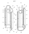
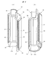
- FIG. 2 is a perspective view of the element assembly in the filter of FIG. 1 cut vertically
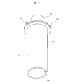
- (A) is a perspective view of the element assembly viewed from above
- (B) is a perspective view of the element assembly viewed from below.
- FIG. 5 shows a cut portion obtained by vertically dividing the element assembly shown in FIG.
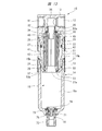
- the filter 10 shown in FIG. 1 has a port block 13 provided with an inflow port 11 and an outflow port 12.
- An air guide member such as a pipe or a hose is connected to the inflow port 11, and the air to be treated is supplied to the filter 10 through the air guide member.
- Air guide members such as pipes and hoses are connected to the outflow port 12, and the purified compressed air flows out from the outflow port 12.
- the filter 10 has a filter container 14, and the filter container 14 is detachably attached to the lower end portion of the port block 13.
- the filter 10 is used with the port block 13 on the upper side and the filter container 14 on the lower side.
- the port block 13 of the filter 10 is attached to a wall surface or the like (not shown) through an attachment (not shown).
- the vertical direction of each member is indicated based on the state in which the filter 10 is used.
- the filter container 14 is provided with a storage chamber 15.
- the filter container 14 shown in FIG. 1 has a first container 16 and a second container 17.
- a liquid discharge hole 18 is provided in the lower end portion of the first container 16, and a female screw portion 19 is provided in the upper end portion of the first container 16.
- the male screw portion 21 is provided at the lower end portion of the second container 17, and the female screw portion 19 is screwed to the male screw portion 21.
- An internal thread portion 22 is provided at the upper end of the second container 17, and the internal thread portion 22 is screwed to the external thread portion 23 of the port block 13. Therefore, the first container 16 is attached to and detached from the second container 17 by rotating the first container 16 with respect to the second container 17.
- the filter container 14 is attached to and detached from the port block 13 by rotating the second container 17 with respect to the port block 13.
- An annular lock member 24 is mounted on the outside of the upper end of the first container 16 so as to be movable up and down. When the lock member 24 is engaged with the second container 17, the rotation of the first container 16 relative to the second container 17 is restricted.
- an annular lock member 25 is mounted on the outside of the upper end portion of the second container 17 so as to be movable up and down. When the lock member 25 is engaged with the port block 13, the rotation of the second container 17 relative to the port block 13 is restricted.
- the seal member 26 seals between the first container 16 and the second container 17, and the seal member 27 seals between the second container 17 and the port block 13.
- the storage chamber 15 is divided into a storage chamber 15 a inside the first container 16 and a filter chamber 15 b inside the second container 17.
- the element assembly 30 is disposed in the filter chamber 15b.
- the element assembly 30 includes a cylindrical filter element 31 having a filtering function and an aggregating function, an upper holder 32 fixed to the upper end portion of the filter element 31, and a lower holder 33 fixed to the lower end portion of the filter element 31. Is provided.
- the filter element 31 is provided between the upper holder 32 and the lower holder 33.
- the upper holder 32 has a flange portion 34 against which the upper end surface of the filter element 31 is abutted.
- a discharge pipe 35 is provided in the flange portion 34, and the discharge pipe 35 protrudes upward.
- the discharge pipe 35 is fitted into the communication hole 36 formed in the port block 13 and attached to the port block 13.
- the discharge pipe 35 communicates with the outflow port 12 through the communication hole 36.
- the lower holder 33 has an annular part 37 and is attached to an annular support part 38 provided in the second container 17.
- the annular portion 37 has a liquid discharge hole 37a, and the liquid discharge hole 37a communicates with the storage chamber 15a.
- the liquid discharge hole 37a is formed by a tapered surface having an inner diameter that increases toward the lower end.
- a flange portion 39 is provided on the annular portion 37, and the flange portion 39 protrudes radially outward from the annular portion 37.
- the lower end surface of the filter element 31 is abutted against the flange portion 39.
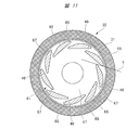
- the air guide member 41 is located inside the filter element 31 and is provided between the upper holder 32 and the lower holder 33. As shown in FIGS. 2 to 4, the air guiding member 41 has a plurality of outer blades 42 and a plurality of inner blades 43. The plurality of outer blades 42 are arranged with a gap in the circumferential direction. The inner blade 43 is disposed radially inward of the outer blade 42 and is disposed with a gap therebetween in the circumferential direction. The outer blade 42 and the inner blade 43 are provided integrally with the upper holder 32.
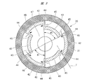
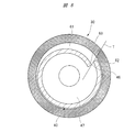
- the embodiment shown in FIG. 3 has three outer blades 42 and three inner blades 43.
- the circumferential angle of the outer blade 42 is ⁇ 1, and the circumferential angle of the inner blade 43 is ⁇ 2.
- the outer blade 42 and the inner blade 43 extend in the circumferential direction, and the angles ⁇ 1 and ⁇ 2 are 60 degrees or more, respectively.
- the outer blade 42 has an outer end 44 in the circumferential direction
- the inner blade 43 has an inner end 45 in the circumferential direction.
- a slit 46 is formed between the outer end 44 of each outer blade 42 and the inner end 45 of the adjacent inner blade 43. Since the outer end 44 and the inner end 45 overlap with each other via the slit 46 in the circumferential direction, the slit 46 is opened in the circumferential direction.
- the tangent line T does not pass through the center of the filter chamber 15 b, that is, the center of the air guide member 41. Since the air guide member 41 shown in FIG. 3 includes three outer blades 42 and three inner blades 43, six slits 46 are formed in the air guide member 41. However, the number of the outer blades 42 and the inner blades 43 constituting the air guide member 41 is not limited to three and can be any number.
- the element assembly 30 includes the upper holder 32, the lower holder 33, the filter element 31 provided therebetween, and the air guide member 41 provided inside the filter element 31. It is formed by assembling the members. As shown in FIG. 1, the element assembly 30 is accommodated in a filter chamber 15 b defined by the port block 13 and the second container 17. A communication passage 51 communicating with the inflow port 11 is formed in the port block 13. The communication path 51 communicates with the inflow space 52 outside the element assembly 30.
- the seal member 53 a seals between the upper holder 32 and the port block 13.
- the seal member 53 b seals between the lower holder 33 and the annular support portion 38.
- the air to be treated that flows into the inflow space 52 from the inflow port 11 passes through the filter element 31.
- Moisture and oil contained in the air to be treated grow into droplets of a certain size while colliding and aggregating in the process of passing through the filter element 31.
- the liquid droplets also contain fine dust that has passed through the filter element 31.
- the grown droplet reaches the inner peripheral surface of the filter element 31 and falls downward along the inner peripheral surface by its own weight. A part of the droplets leaves the inner peripheral surface of the filter element in the middle of dropping, collides with and adheres to the outer wall of the air guide member 41, moves downward along the outer wall of the air guide member 41, and stores the storage chamber 15 a. Fall towards the. Further, some droplets enter the inner space 47 through the slit 46 without colliding with the outer wall of the air guide member 41.
- Compressed air that has passed through the filter element 31 enters the gap between the air guide member 41 and the filter element 31, and then flows into the inner space 47 inside the air guide member 41 from each slit 46.
- the compressed air flowing into the inner space 47 passes through the slit 46 in the circumferential direction without going directly to the center of the inner space 47 and then flows into the inner space 47 as indicated by arrows in FIG. To do.
- the compressed air that has flowed into the inner space 47 from the slit 46 is blown toward the inner surface of the inner blade 43.
- Two slits 46 are located inside the outer blade 42 so as to face each other.
- the compressed air that has passed through the two opposing slits 46 flows in the circumferential direction when passing through the slit 46 and collides in the vicinity of the center inside the outer blade 42.
- the two compressed air flows that have collided change their direction from the circumferential direction to the radial direction and head toward the center.
- Near the center of the inner side of the outer blade 42 where the two compressed airs collide is a puddle region.
- the accumulation area is formed in the center of the inner wall of the outer blade 42 along the axial direction. Since the size of the droplet collected in the accumulation area further grows, it quickly falls along the inner wall of the outer blade 42 by its own weight.
- the droplets adhering to the outside of the air guide member 41 and the inner surface of the outer blade 42 have a certain size, and move to the center of the inner space 47 even if the flow rate of the compressed air suddenly changes. It is prevented. Thereby, foreign matter is prevented from flowing out from the discharge pipe 35 toward the outflow port 12, and the removal efficiency of the foreign matter by the filter 10 can be enhanced.
- a small-diameter guide tube 48 is provided on the flange portion 34 of the upper holder 32 and protrudes downward.
- the small diameter guide tube 48 protrudes inward in the radial direction of the air guide member 41.
- a blocking space 49 that opens downward is provided between the small-diameter guide tube 48 and the upper end of the air guide member 41.
- the blocking space 49 prevents droplets attached to the inner surfaces of the inner blade 43 and the outer blade 42 from moving along the surface toward the small diameter guide tube 48 and the discharge tube 35. Accordingly, foreign matter does not enter the compressed air flowing from the inner space 47 toward the discharge pipe 35.
- a discharge pipe 54 is provided in the liquid discharge hole 18, and foreign substances such as liquid droplets accumulated in the storage chamber 15 a are discharged to the outside through the discharge pipe 54.
- the leg part 55 is comprised from four plate-shaped members, and is arrange
- a seal member 56 for sealing the liquid discharge hole 18 is provided on the leg portion 55.
- An operation knob 57 is rotatably attached to the lower end portion of the filter container 14 and meshes with the discharge pipe 54.
- a baffle plate 58 is disposed on the leg 55, and the baffle plate 58 faces the liquid discharge hole 37a.
- a plurality of fins 59 are provided on the outer periphery of the baffle plate 58. Each fin 59 protrudes upward and extends in the radial direction.
- the liquid droplets that have fallen into the storage chamber 15a through the liquid discharge hole 37a are guided toward the inner peripheral surface of the second container 17 by the fins 59 and collected in the lower portion of the storage chamber 15a.
- the filter container 14 is formed of a transparent resin material, and the amount of liquid stored in the storage chamber 15a is visually observed from the outside. When it is visually observed that the amount of liquid has increased, the operator operates the operation knob 57 to discharge foreign matters such as liquid in the storage chamber 15a to the outside.
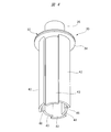
- FIG. 5 is a longitudinal sectional view showing an element assembly 30 which is a modified example. 6 shows a cut portion obtained by vertically dividing the element assembly 30 shown in FIG. 5, and FIG. 6A is a perspective view of the cross section of the element assembly 30 as viewed from above, and FIG. FIG. 3 is a perspective view of a cross section of the element assembly 30 as viewed from below.
- the small diameter guide tube 48 shown in FIGS. 1 and 2 is not provided in the upper holder 32. As described above, even in a form in which the small-diameter guide tube 48 is not provided, the foreign matter removal efficiency can be increased.
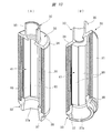
- FIG. 7 shows a cut portion obtained by vertically dividing an element assembly 30 which is another modified example
- FIG. 7A is a perspective view of the cross section of the element assembly 30 as viewed from above
- FIG. FIG. 3 is a perspective view of a cross section of the element assembly 30 as viewed from below
- 8 is a cross-sectional view of the element assembly 30 shown in FIG. 7
- FIG. 9 is a perspective view showing the air guide member 41 and the upper holder 32 of the element assembly 30 shown in FIG.
- the air guide member 41 is formed by a single blade member 61 having a spiral shape in the circumferential direction.
- a slit 46 is formed between the circumferential ends 62 and 63 of the blade member 61. Both end portions 62 and 63 overlap in the circumferential direction through the slit 46, and the slit 46 opens in the circumferential direction.
- a tangent line T connecting the edge of the outer end portion 62 and the edge of the inner end portion 63 does not pass through the center of the filter chamber 15b, that is, the center of the air guide member 41, as in the air guide member 41 shown in FIG.
- the compressed air flowing into the inner space 47 does not go directly to the center of the inner space 47, passes through the slit 46 in the circumferential direction, and then flows into the inner space 47.
- the compressed air flowing into the inner space 47 from the slit 46 is blown toward the inner surface of the blade member 61. Accordingly, the liquid droplets that flow into the inner space 47 from the slit 46 adhere to the inner surface of the blade member 61, and are thus prevented from scattering toward the discharge pipe 35. Thereby, the removal efficiency of the foreign material by the filter 10 can be improved.
- the upper holder 32 is provided with a small diameter guide tube 48.
- the upper holder 32 may not be provided with the small diameter guide tube 48.
- FIG. 10 shows a cut portion obtained by vertically dividing an element assembly which is still another modified example.
- FIG. 10 (A) is a perspective view of the element assembly as viewed from above.
- FIG. 10 (B) is an element assembly. It is the perspective view which looked at the solid from the lower part.
- FIG. 11 is a cross-sectional view of the element assembly shown in FIG. 12 is a perspective view showing an air guide member and an upper holder in the element assembly shown in FIG.
- the air guide member 41 is formed by a plurality of inclined blades 65 inclined in the circumferential direction.
- Each inclined blade 65 has an outer end 66 in the circumferential direction and an inner end 67 in the circumferential direction.
- the inner end portion 67 is located radially inward from the outer end portion 66 of the adjacent inclined blade 65.
- the inclined blades 65 are inclined such that the outer end portions 66 are located on the outer side with respect to a reference circle passing through the central portion of each inclined blade 65 and the inner end portion 67 is located on the inner side.
- a plurality of slits 46 are formed between each inner end portion 67 and the outer end portion 66 of another inclined blade 65 adjacent thereto. Each slit 46 is opened in a direction along the inner surface of the inclined blade 65.
- the droplet that has grown large while passing through the filter element 31 falls along the inside of the filter element 31. Most of the liquid droplets that have fallen from the inside of the filter element 31 without falling are collided and adhered to the outer wall of the inclined blade 65 and fall. The droplets that have not collided with the outer wall of the inclined blade 65 flow into the inner space 47 from the slit 46, are sprayed toward the inner surface of the inclined blade 65 by the compressed air, and adhere to the inner surface of the inclined blade 65.
- the tangent line T connecting the edge of the outer end portion 66 and the edge of the inner end portion 67 does not pass through the center of the filter chamber 15b, that is, the center of the air guide member 41, like the air guide member 41 described above. Therefore, the compressed air that has passed through the slit 46 does not go directly to the center of the inner space 47, passes through the slit 46 in the circumferential direction, and then flows into the inner space 47. Therefore, the compressed air swirls in the inner space 47.
- the compressed air increases in speed by swirling.
- the droplets contained in the compressed air collide with and adhere to the inner surface of the inclined blade 65 at a high speed.
- Increasing the speed of the compressed air by swirling improves the efficiency of droplet collision and adhesion to the inner surface of the inclined blade 65.
- By increasing the speed more droplets collide with and adhere to the inner surface of the inclined blade 65 and fall, so that the droplets are prevented from flowing out toward the discharge pipe 35. Thereby, the removal efficiency of the foreign material by the filter 10 can be improved.
- the plurality of fins 59 have the following effects. That is, the compressed air flows from the liquid discharge hole 37 a toward the storage chamber 15 a while turning, but the turning is suppressed by the fins 59. The compressed air whose rotation is suppressed flows through the center of the air guide member 41 and travels toward the discharge pipe 35.
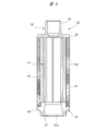
- FIG. 13 is a longitudinal sectional view showing a filter 10 according to another embodiment.
- the element assembly 30 in the filter 10 has the same structure as that shown in FIGS.
- the leg 55 and the baffle plate 58 shown in FIG. 1 are not provided.
- a sleeve 71 having a liquid discharge hole 18 is provided at the bottom of the filter container 14, and a discharge pipe 72 as a drain cock is screwed to the sleeve 71.
- An on-off valve body 74 engages with the discharge pipe 72 and opens and closes a valve seat seal 73 provided on the filter container 14.
- the air guide member 41 is formed integrally with the upper holder 32.
- the air guide member 41 may be formed integrally with the lower holder 33.
- the air guide member 41 may be formed as a separate member from the upper holder 32 and the lower holder 33.
- the liquid droplets that have grown to a certain size due to aggregation of moisture and oil by passing through the filter element 31 fall along the inner surface of the filter element 31. Since the liquid droplets detached from the inner surface of the filter element 31 are sprayed on the outer surface and the inner surface of the air guide member 41, the liquid droplets adhere to the outer surface and the inner surface of the air guide member 41 and fall. In this way, foreign matter is prevented from entering the compressed air toward the outflow port 12.
- the illustrated filter 10 is a drain filter that discharges foreign matters such as liquid accumulated in the storage chamber 15a to the outside by manual operation.
- the present invention can also be applied to an auto drain type filter that automatically discharges foreign matter to the outside.
- This invention is used to remove foreign substances contained in compressed air in a pneumatic circuit that supplies compressed air supplied from a pneumatic pressure source to pneumatic equipment.
Landscapes
- Chemical & Material Sciences (AREA)
- Chemical Kinetics & Catalysis (AREA)
- Engineering & Computer Science (AREA)
- Mechanical Engineering (AREA)
- General Engineering & Computer Science (AREA)
- Physics & Mathematics (AREA)
- Geometry (AREA)
- Filtering Of Dispersed Particles In Gases (AREA)
- Separating Particles In Gases By Inertia (AREA)
Priority Applications (3)
| Application Number | Priority Date | Filing Date | Title |
|---|---|---|---|
| CN201590001406.XU CN207286977U (zh) | 2015-03-26 | 2015-08-26 | 元件组装体及过滤器 |
| DE112015006372.2T DE112015006372B4 (de) | 2015-03-26 | 2015-08-26 | Elementanordnung und filter |
| US15/561,114 US10561973B2 (en) | 2015-03-26 | 2015-08-26 | Element assembly and filter |
Applications Claiming Priority (2)
| Application Number | Priority Date | Filing Date | Title |
|---|---|---|---|
| JP2015-063534 | 2015-03-26 | ||
| JP2015063534A JP6370251B2 (ja) | 2015-03-26 | 2015-03-26 | エレメント組立体およびフィルタ |
Publications (1)
| Publication Number | Publication Date |
|---|---|
| WO2016151883A1 true WO2016151883A1 (ja) | 2016-09-29 |
Family
ID=56978114
Family Applications (1)
| Application Number | Title | Priority Date | Filing Date |
|---|---|---|---|
| PCT/JP2015/074096 WO2016151883A1 (ja) | 2015-03-26 | 2015-08-26 | エレメント組立体およびフィルタ |
Country Status (6)
Cited By (2)
| Publication number | Priority date | Publication date | Assignee | Title |
|---|---|---|---|---|
| CN109954330A (zh) * | 2017-12-14 | 2019-07-02 | 费斯托股份有限两合公司 | 用于对压缩空气进行过滤的过滤装置 |
| CN117552958A (zh) * | 2024-01-12 | 2024-02-13 | 山西省第二地质工程勘察院有限公司 | 一种空压机进气系统 |
Families Citing this family (4)
| Publication number | Priority date | Publication date | Assignee | Title |
|---|---|---|---|---|
| JP6436827B2 (ja) * | 2015-03-26 | 2018-12-12 | 株式会社コガネイ | エレメント組立体およびフィルタ |
| US10408492B2 (en) * | 2016-01-15 | 2019-09-10 | Hamilton Sundstrand Corporation | Drain hole orifice device |
| US20180172041A1 (en) * | 2016-12-20 | 2018-06-21 | Baker Hughes Incorporated | Temperature regulated components having cooling channels and method |
| TWI789909B (zh) * | 2021-09-16 | 2023-01-11 | 玖鑢豪科技股份有限公司 | 空氣過濾器 |
Citations (4)
| Publication number | Priority date | Publication date | Assignee | Title |
|---|---|---|---|---|
| JPH07204440A (ja) * | 1994-01-28 | 1995-08-08 | Koganei Corp | エアフィルタ |
| EP1155724A1 (de) * | 2000-05-19 | 2001-11-21 | Munters Euroform GmbH | Filterkerze |
| JP2012020242A (ja) * | 2010-07-15 | 2012-02-02 | Tlv Co Ltd | 気液分離器 |
| JP2013000659A (ja) * | 2011-06-16 | 2013-01-07 | Tlv Co Ltd | 気液分離器 |
Family Cites Families (24)
| Publication number | Priority date | Publication date | Assignee | Title |
|---|---|---|---|---|
| US2828831A (en) * | 1953-11-02 | 1958-04-01 | Gen Motors Corp | Fluid cleaner |
| US3208229A (en) * | 1965-01-28 | 1965-09-28 | Fulton Cryogenics Inc | Vortex tube |
| US3771295A (en) * | 1969-07-31 | 1973-11-13 | H Wheeler | Separater apparatus for handling compressed air |
| DE2219846A1 (de) | 1972-04-22 | 1973-10-31 | Haas & Sohn Ernst W | Luftreiniger, vorzugsweise fuer die raumluftreinigung |
| SE465813B (sv) * | 1990-03-23 | 1991-11-04 | Sundstrom Safety Ab | Cyklonkammare med droppavskiljare |
| US5119640A (en) * | 1990-10-22 | 1992-06-09 | Conrad Richard H | Freeze-thaw air dryer |
| US5591243A (en) * | 1993-09-10 | 1997-01-07 | Col-Ven S.A. | Liquid trap for compressed air |
| US6032804A (en) * | 1997-06-16 | 2000-03-07 | Paulson; Jerome I | Cyclonic dust collector |
| US5846271A (en) * | 1997-07-08 | 1998-12-08 | Reading Technologies, Inc. | Multi-stage compressed gas filter |
| US6004365A (en) | 1997-10-17 | 1999-12-21 | Fiacco; Paul | Air filtering device |
| WO1999030799A1 (en) * | 1997-12-15 | 1999-06-24 | Domnick Hunter Limited | Filter assembly |
| US6093227A (en) * | 1998-08-27 | 2000-07-25 | Itt Manufacturing Enterprises, Inc. | Air filter with labyrinth air flow pattern through an air filter insert |
| CN2486746Y (zh) * | 2001-07-12 | 2002-04-17 | 陈栢辉 | 气压式空气除水装置 |
| GB0515266D0 (en) * | 2005-07-26 | 2005-08-31 | Domnick Hunter Ltd | Separator assembly |
| DE202006006084U1 (de) * | 2006-04-12 | 2007-08-16 | Mann + Hummel Gmbh | Mehrstufige Vorrichtung zum Abscheiden von Flüssigkeitstropfen aus Gasen |
| JP5663394B2 (ja) * | 2011-05-06 | 2015-02-04 | 株式会社コガネイ | 調質機器の容器着脱装置 |
| JP5713289B2 (ja) | 2011-05-09 | 2015-05-07 | Smc株式会社 | 流体圧機器のケース構造 |
| JP5765560B2 (ja) | 2011-05-09 | 2015-08-19 | Smc株式会社 | フィルタ装置 |
| JP5666379B2 (ja) * | 2011-05-19 | 2015-02-12 | 株式会社コガネイ | 旋回流発生器 |
| DE112012001826B4 (de) * | 2011-05-19 | 2023-08-17 | Koganei Corporation | Filter |
| TW201515711A (zh) * | 2013-10-31 | 2015-05-01 | Koganei Ltd | 過濾器 |
| JP6226789B2 (ja) * | 2014-03-20 | 2017-11-08 | 株式会社コガネイ | フィルタレギュレータ |
| US9689310B2 (en) * | 2014-05-06 | 2017-06-27 | William BOATENG | Airplane engine bird strike protection guard |
| JP6436827B2 (ja) * | 2015-03-26 | 2018-12-12 | 株式会社コガネイ | エレメント組立体およびフィルタ |
-
2015
- 2015-03-26 JP JP2015063534A patent/JP6370251B2/ja active Active
- 2015-08-26 DE DE112015006372.2T patent/DE112015006372B4/de active Active
- 2015-08-26 WO PCT/JP2015/074096 patent/WO2016151883A1/ja active Application Filing
- 2015-08-26 US US15/561,114 patent/US10561973B2/en active Active
- 2015-08-26 CN CN201590001406.XU patent/CN207286977U/zh not_active Expired - Fee Related
- 2015-11-13 TW TW104137584A patent/TWI645890B/zh active
Patent Citations (4)
| Publication number | Priority date | Publication date | Assignee | Title |
|---|---|---|---|---|
| JPH07204440A (ja) * | 1994-01-28 | 1995-08-08 | Koganei Corp | エアフィルタ |
| EP1155724A1 (de) * | 2000-05-19 | 2001-11-21 | Munters Euroform GmbH | Filterkerze |
| JP2012020242A (ja) * | 2010-07-15 | 2012-02-02 | Tlv Co Ltd | 気液分離器 |
| JP2013000659A (ja) * | 2011-06-16 | 2013-01-07 | Tlv Co Ltd | 気液分離器 |
Cited By (3)
| Publication number | Priority date | Publication date | Assignee | Title |
|---|---|---|---|---|
| CN109954330A (zh) * | 2017-12-14 | 2019-07-02 | 费斯托股份有限两合公司 | 用于对压缩空气进行过滤的过滤装置 |
| CN117552958A (zh) * | 2024-01-12 | 2024-02-13 | 山西省第二地质工程勘察院有限公司 | 一种空压机进气系统 |
| CN117552958B (zh) * | 2024-01-12 | 2024-03-22 | 山西省第二地质工程勘察院有限公司 | 一种空压机进气系统 |
Also Published As
| Publication number | Publication date |
|---|---|
| CN207286977U (zh) | 2018-05-01 |
| DE112015006372T5 (de) | 2017-12-14 |
| US20180126312A1 (en) | 2018-05-10 |
| DE112015006372B4 (de) | 2021-12-30 |
| JP2016182548A (ja) | 2016-10-20 |
| US10561973B2 (en) | 2020-02-18 |
| TW201634102A (zh) | 2016-10-01 |
| JP6370251B2 (ja) | 2018-08-08 |
| TWI645890B (zh) | 2019-01-01 |
Similar Documents
| Publication | Publication Date | Title |
|---|---|---|
| JP6436827B2 (ja) | エレメント組立体およびフィルタ | |
| JP6370251B2 (ja) | エレメント組立体およびフィルタ | |
| JP5628089B2 (ja) | フィルタ | |
| JP5819716B2 (ja) | フィルタ | |
| JP5767322B2 (ja) | フィルタ | |
| WO2015033414A1 (ja) | 気液分離装置 | |
| EP2535099A2 (de) | Luftfilterelement, Filtergehäuse und Filteranordnung | |
| WO2012157146A1 (ja) | 旋回流発生器 | |
| KR102229357B1 (ko) | 페인트부스 공기정화장치 | |
| JP5890797B2 (ja) | エアフィルタ | |
| KR20230089120A (ko) | 응축수 배출 장치용 필터 | |
| JP2010172821A (ja) | フィルタ装置 | |
| WO2012157139A1 (ja) | フィルタ | |
| WO2016151881A1 (ja) | エレメント組立体およびフィルタ | |
| WO2013012003A1 (ja) | フィルタ | |
| US20170107772A1 (en) | Shale-Gas Separator Discharge Diffuser | |
| JP2016182549A (ja) | フィルタ | |
| CN106693523A (zh) | 旋风式过滤装置 | |
| UA68515A (en) | Filter for removal of admixtures from transported gas | |
| HU188757B (en) | Device for separating contaminations first solid ones being in gas by using of wash liquor |
Legal Events
| Date | Code | Title | Description |
|---|---|---|---|
| 121 | Ep: the epo has been informed by wipo that ep was designated in this application |
Ref document number: 15886435 Country of ref document: EP Kind code of ref document: A1 |
|
| WWE | Wipo information: entry into national phase |
Ref document number: 15561114 Country of ref document: US |
|
| WWE | Wipo information: entry into national phase |
Ref document number: 112015006372 Country of ref document: DE |
|
| 122 | Ep: pct application non-entry in european phase |
Ref document number: 15886435 Country of ref document: EP Kind code of ref document: A1 |