WO2016151854A1 - 温度計算方法、温度計算装置、加熱制御方法、及び加熱制御装置 - Google Patents
温度計算方法、温度計算装置、加熱制御方法、及び加熱制御装置 Download PDFInfo
- Publication number
- WO2016151854A1 WO2016151854A1 PCT/JP2015/059433 JP2015059433W WO2016151854A1 WO 2016151854 A1 WO2016151854 A1 WO 2016151854A1 JP 2015059433 W JP2015059433 W JP 2015059433W WO 2016151854 A1 WO2016151854 A1 WO 2016151854A1
- Authority
- WO
- WIPO (PCT)
- Prior art keywords
- temperature
- region
- width direction
- steel plate
- plate
- Prior art date
- Legal status (The legal status is an assumption and is not a legal conclusion. Google has not performed a legal analysis and makes no representation as to the accuracy of the status listed.)
- Ceased
Links
Images


Classifications
-
- B—PERFORMING OPERATIONS; TRANSPORTING
- B21—MECHANICAL METAL-WORKING WITHOUT ESSENTIALLY REMOVING MATERIAL; PUNCHING METAL
- B21B—ROLLING OF METAL
- B21B37/00—Control devices or methods specially adapted for metal-rolling mills or the work produced thereby
- B21B37/74—Temperature control, e.g. by cooling or heating the rolls or the product
- B21B37/76—Cooling control on the run-out table
-
- B—PERFORMING OPERATIONS; TRANSPORTING
- B21—MECHANICAL METAL-WORKING WITHOUT ESSENTIALLY REMOVING MATERIAL; PUNCHING METAL
- B21B—ROLLING OF METAL
- B21B38/00—Methods or devices for measuring, detecting or monitoring specially adapted for metal-rolling mills, e.g. position detection, inspection of the product
- B21B38/006—Methods or devices for measuring, detecting or monitoring specially adapted for metal-rolling mills, e.g. position detection, inspection of the product for measuring temperature
-
- B—PERFORMING OPERATIONS; TRANSPORTING
- B21—MECHANICAL METAL-WORKING WITHOUT ESSENTIALLY REMOVING MATERIAL; PUNCHING METAL
- B21B—ROLLING OF METAL
- B21B45/00—Devices for surface or other treatment of work, specially combined with or arranged in, or specially adapted for use in connection with, metal-rolling mills
- B21B45/004—Heating the product
-
- C—CHEMISTRY; METALLURGY
- C21—METALLURGY OF IRON
- C21D—MODIFYING THE PHYSICAL STRUCTURE OF FERROUS METALS; GENERAL DEVICES FOR HEAT TREATMENT OF FERROUS OR NON-FERROUS METALS OR ALLOYS; MAKING METAL MALLEABLE, e.g. BY DECARBURISATION OR TEMPERING
- C21D11/00—Process control or regulation for heat treatments
-
- C—CHEMISTRY; METALLURGY
- C21—METALLURGY OF IRON
- C21D—MODIFYING THE PHYSICAL STRUCTURE OF FERROUS METALS; GENERAL DEVICES FOR HEAT TREATMENT OF FERROUS OR NON-FERROUS METALS OR ALLOYS; MAKING METAL MALLEABLE, e.g. BY DECARBURISATION OR TEMPERING
- C21D8/00—Modifying the physical properties of ferrous metals or ferrous alloys by deformation combined with, or followed by, heat treatment
- C21D8/02—Modifying the physical properties of ferrous metals or ferrous alloys by deformation combined with, or followed by, heat treatment during manufacturing of plates or strips
-
- C—CHEMISTRY; METALLURGY
- C21—METALLURGY OF IRON
- C21D—MODIFYING THE PHYSICAL STRUCTURE OF FERROUS METALS; GENERAL DEVICES FOR HEAT TREATMENT OF FERROUS OR NON-FERROUS METALS OR ALLOYS; MAKING METAL MALLEABLE, e.g. BY DECARBURISATION OR TEMPERING
- C21D8/00—Modifying the physical properties of ferrous metals or ferrous alloys by deformation combined with, or followed by, heat treatment
- C21D8/02—Modifying the physical properties of ferrous metals or ferrous alloys by deformation combined with, or followed by, heat treatment during manufacturing of plates or strips
- C21D8/0221—Modifying the physical properties of ferrous metals or ferrous alloys by deformation combined with, or followed by, heat treatment during manufacturing of plates or strips characterised by the working steps
- C21D8/0226—Hot rolling
-
- B—PERFORMING OPERATIONS; TRANSPORTING
- B21—MECHANICAL METAL-WORKING WITHOUT ESSENTIALLY REMOVING MATERIAL; PUNCHING METAL
- B21B—ROLLING OF METAL
- B21B2261/00—Product parameters
- B21B2261/20—Temperature
-
- B—PERFORMING OPERATIONS; TRANSPORTING
- B21—MECHANICAL METAL-WORKING WITHOUT ESSENTIALLY REMOVING MATERIAL; PUNCHING METAL
- B21B—ROLLING OF METAL
- B21B37/00—Control devices or methods specially adapted for metal-rolling mills or the work produced thereby
- B21B37/74—Temperature control, e.g. by cooling or heating the rolls or the product
Definitions
- the present invention relates to a temperature calculation method, a temperature calculation device, a heating control method, and a heating control device.
- Patent Document 1 discloses an apparatus for calculating a temperature distribution of a cross section perpendicular to the longitudinal direction of a steel plate in hot rolling.
- the apparatus of Patent Literature 1 divides a plurality of elements in a ring shape for each space step width from the outer periphery to the center in the cross section of the steel sheet, and calculates a predicted temperature for each divided element by a difference method.
- an edge heater may be provided in the rolling line.
- An edge heater heats only the edge part of a steel plate by induction heating.
- Patent Document 2 the amount of heat removed from the edge portion due to air cooling, coolant, and roll contact between the edge heater and the rolling mill is calculated, so that the edge portion reaches the target temperature on the entry side of the rolling mill, A method of correcting the heating amount by the edge heater is disclosed.
- the apparatus of Patent Document 1 calculates a representative temperature of each divided ring-shaped element.
- the outermost elements include the upper and side surfaces of the steel sheet. Therefore, the calculation result by the apparatus of Patent Document 1 shows that the upper surface temperature and the side surface temperature of the steel plate are equal.
- Patent Document 2 uses a simple formula based on variables that affect the amount of heat removal, such as coolant pressure and plate speed.
- the coefficient of the simplified formula needs to be obtained experimentally. Therefore, in order to improve the calculation accuracy, it is necessary to conduct experiments on various steel types and sizes to obtain the coefficient.
- An object of the present invention is to provide a temperature calculation method, a temperature calculation device, a heating control method, and a heating control device that contribute to improving the quality of a steel sheet that is hot rolled, including the edge portion, while suppressing the calculation load. It is to provide.
- the temperature calculation method of the present invention divides a cross section perpendicular to the longitudinal direction of a steel sheet to be hot-rolled into a plurality of rectangular elements, and calculates the temperature of each rectangular element using a finite difference method.
- the first region which is a region including the edge portion of the cross section is divided so that the plurality of rectangular elements are arranged in the plate thickness direction and the plurality of rectangular elements are arranged in the plate width direction, and includes the center of the cross section
- the second region which is a region wider than the first region, is divided so that a plurality of rectangular elements are arranged in the plate thickness direction, and is not divided in the plate width direction.
- the heating control method of the present invention measures the temperature difference between the representative temperature of the second region and the representative temperature of the first region at a position downstream of the edge heater that heats the edge portion of the steel sheet, and the above temperature calculation. Calculating the temperature difference using the method and controlling the output or heating amount of the edge heater based on the measured value of the temperature difference, the calculated value of the temperature difference, and the target value of the temperature difference; Is included.
- the temperature calculation apparatus includes means for dividing a cross section perpendicular to the longitudinal direction of a steel sheet to be hot-rolled into a plurality of rectangular elements, and means for calculating the temperature of each rectangular element using a finite difference method. And a first region that is an area including an edge portion of the cross section is divided so that the plurality of rectangular elements are arranged in the plate thickness direction and the plurality of rectangular elements are arranged in the plate width direction, and includes the center of the cross section. The second region, which is a region wider than the first region, is divided so that a plurality of rectangular elements are arranged in the plate thickness direction, and is not divided in the plate width direction.
- the heating control device of the present invention measures the temperature difference between the representative temperature of the second region and the representative temperature of the first region at a position downstream of the temperature calculation device and the edge heater that heats the edge portion of the steel plate.
- the output of the edge heater or the heating amount based on the measured value of the temperature difference, the calculated value of the temperature difference, the calculated value of the temperature difference, and the target value of the temperature difference.
- means for controlling is provided.
- the present invention it is possible to accurately calculate the temperature distribution of a hot-rolled steel sheet including the edge part, and to contribute to improving the quality of the steel sheet including the edge part.
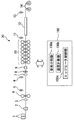
- FIG. 1 It is a block diagram which shows the rolling system with which Embodiment 1 of this invention is applied. It is a hardware block diagram of the control apparatus with which the rolling system shown in FIG. 1 is provided. It is a figure which shows the state by which the cross section perpendicular
- FIG. 1 is a configuration diagram showing a rolling system to which Embodiment 1 of the present invention is applied.
- 1 includes a slab heating furnace 1, a high-pressure descaling device 2, an edger 3, a roughing mill 4, a first thermometer 5, a second thermometer 6, an edge heater 7, a crop shear 8, and finishing input.
- a side descaling device 9, a finishing mill 10, a third thermometer 11, a run-out laminar spray cooling device 12, a fourth thermometer 13, a coiler 14, and a control device 100 are provided.
- the steel sheet hot-rolled by the rolling system 20 is conveyed in the longitudinal direction of the steel sheet (lateral direction in FIG. 1).
- the direction perpendicular to both the longitudinal direction and the plate thickness direction of the steel plate is the plate width direction.
- the plate width of the steel plate is, for example, about 900 mm to 2000 mm.
- the thickness of the steel plate (slab) before being rolled is, for example, about 200 mm to 250 mm.
- the plate thickness of the steel plate exiting the finish rolling mill 10 is, for example, about 1 mm to 25 mm.
- the slab heating furnace 1 heats a steel plate (slab) before being rolled to about 1200 ° C., for example.
- the high pressure descaling device 2 removes the scale from the surface of the steel sheet by injecting high pressure water from above and below the steel sheet exiting the slab heating furnace 1.
- the edger 3 performs rolling in the sheet width direction of the steel sheet.
- the rough rolling machine 4 performs rough rolling in the thickness direction of the steel sheet.
- the first thermometer 5 measures the temperature of the steel sheet roughly rolled by the rough rolling machine 4.
- the second thermometer 6 measures the temperature of the steel plate before being heated by the edge heater 7.
- the edge heater 7 heats an edge portion extending in the longitudinal direction of the steel plate by induction heating.
- the edge heater 7 has induction heating coils that are paired so as to sandwich the pass line of the steel plate from above and below.
- the edge heater 7 generates an eddy current at the edge portion of the steel sheet by a magnetic field generated by flowing a high-frequency current through the induction heating coil, and heats only the edge portion of the steel sheet by the Joule heat.
- the crop shear 8 cuts the tip and tail ends of the steel plate.
- the finish entry side descaling device 9 removes the scale from the surface of the steel sheet on the entry side of the finish rolling mill 10.
- the finish rolling mill 10 finish-rolls the steel plate to a predetermined plate thickness.
- the third thermometer 11 measures the temperature of the steel sheet finish-rolled by the finish rolling mill 10.
- the run-out laminar spray cooling device 12 cools the steel plate.
- the fourth thermometer 13 measures the temperature of the steel sheet cooled by the run-out laminar spray cooling device 12.
- the coiler 14 winds up a steel plate.
- the first thermometer 5, the second thermometer 6, the third thermometer 11, and the fourth thermometer 13 are radiation thermometers.
- the 1st thermometer 5, the 2nd thermometer 6, the 3rd thermometer 11, and the 4th thermometer 13 measure the temperature of the surface (upper surface) of a steel plate.
- the control device 100 is connected to each facility described above included in the rolling system 20.
- the control device 100 includes an element dividing unit 100a, a temperature calculating unit 100b, and an edge heater control unit 100c in terms of its functions.
- the element dividing unit 100a executes a step of dividing a cross section perpendicular to the longitudinal direction of a steel sheet hot-rolled in the rolling system 20 into a plurality of rectangular elements for temperature calculation.
- the temperature calculation unit 100b executes a step of calculating the temperature of each rectangular element divided by the element division unit 100a using a finite difference method.
- the temperature calculation unit 100b calculates a predicted temperature or an estimated temperature of each rectangular element.
- the edge heater control unit 100c executes a step of controlling the output or heating amount of the edge heater 7 based on the calculation result of the temperature calculation unit 100b. Further, the control device 100 may calculate or control various amounts (rolling load, rolling torque, cooling water amount, etc.) of the rolling process using the calculation result of the temperature calculation unit 100b.
- FIG. 2 is a hardware configuration diagram of the control device 100 included in the rolling system 20 shown in FIG.
- the control device 100 includes a processor 101, a ROM (Read Only Memory) 102, a RAM (Random Access Memory) 103, a receiving device 104, a transmitting device 105, a hard disk drive 106, and A bus 200 is provided.
- the processor 101, the ROM 102, the RAM 103, the receiving device 104, the transmitting device 105, and the hard disk drive 106 are connected to each other via the bus 200.
- the ROM 102, the RAM 103, and the hard disk drive 106 are storage devices.
- the ROM 102 is configured by a nonvolatile semiconductor or the like, and stores programs such as an operation system executed by the processor 101.
- the RAM 103 is composed of a volatile semiconductor or the like, and temporarily stores programs and data necessary for the processor 101 to execute various processes.
- the hard disk drive 106 stores a program executed by the processor 101.
- the receiving device 104 receives temperature information measured by the first thermometer 5, the second thermometer 6, the third thermometer 11, and the fourth thermometer 13 of the rolling system 20. Furthermore, the receiving device 104 receives process values and the like detected by other sensors (not shown) provided in the rolling system 20.
- the transmission device 105 sends various control signals generated by the processor 101 to the high-pressure descaling device 2, the edger 3, the roughing mill 4, the edge heater 7, the crop shear 8, the finishing input side descaling device 9, and the finishing mill. 10, and transmit to each equipment such as the run-out laminar spray cooling device 12 and the coiler 14.
- the functions and operations of the element division unit 100a, the temperature calculation unit 100b, the edge heater control unit 100c, etc. of the control device 100 are realized by the processor 101 executing a program stored in the storage device.
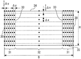
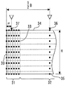
- FIG. 3 is a diagram illustrating a state in which a cross section perpendicular to the longitudinal direction of the steel sheet is divided into a plurality of rectangular elements.
- the width of the steel plate is B.
- the plate thickness of the steel plate is H.
- the broken line in FIG. 3 shows the boundary between rectangular elements.
- the side surface 30 of the steel plate is a side surface extending in the longitudinal direction of the steel plate.
- the element dividing unit 100 a divides a cross section perpendicular to the longitudinal direction of the steel sheet into a first region 31 and a second region 32.
- the first region 31 is a region including an edge portion of the cross section.
- the first region 31 is a region including the side surface 30 of the steel plate.
- the second region 32 is a region including the center of the cross section in the plate width direction.
- the second area 32 is an area wider than the first area 31.
- the second area 32 is all areas excluding the first area 31 from the cross section.
- the region boundary 33 is a boundary between the first region 31 and the second region 32.
- the region boundary 33 is parallel to the side surface 30 of the steel plate.
- the length of the first region 31 in the plate width direction that is, the distance from the side surface 30 of the steel plate to the region boundary 33 is smaller than the length of the second region 32 in the plate width direction.
- the element dividing unit 100a divides the first region 31 so that a plurality of rectangular elements are arranged in the thickness direction in the first region 31.
- the element dividing unit 100 a divides the first region 31 so that a plurality of rectangular elements are arranged in the plate width direction in the first region 31. That is, the element dividing unit 100a divides the first region 31 in the plate thickness direction and the plate width direction.
- the element dividing unit 100a divides the second region 32 so that a plurality of rectangular elements are arranged in the thickness direction in the second region 32.
- the element dividing unit 100a does not divide the second region 32 in the plate width direction. That is, the element dividing unit 100a divides the second region 32 only in the plate thickness direction and does not divide it in the plate width direction.
- the length of the rectangular element in the second region 32 in the plate width direction is equal to the length of the second region 32 itself in the plate width direction.
- the rectangular element in the second region 32 is overwhelmingly longer in the plate width direction than in the plate thickness direction. That is, the rectangular element of the second region 32 is elongated.
- the two-dimensional temperature distribution of this cross section can be accurately calculated.
- the number of divisions in the thickness direction of the first region 31 and the number of divisions in the thickness direction of the second region 32 are desirably equal.
- the number of rectangular elements arranged in the thickness direction from the center in the thickness direction to the upper surface 34 or the lower surface 35 of the steel plate is NT.
- NT 5
- the number of rectangular elements arranged in the thickness direction from the upper surface 34 to the lower surface 35 of the steel plate is 2NT-1.
- the length in the plate thickness direction of the rectangular element excluding the rectangular element including the upper surface 34 of the steel plate and the rectangular element including the lower surface 35 of the steel plate is defined as ⁇ x.
- the length of the rectangular element including the upper surface 34 of the steel plate in the thickness direction is ⁇ x / 2.
- the length in the plate thickness direction of the rectangular element including the lower surface 35 of the steel plate is ⁇ x / 2.
- the rectangular elements excluding the rectangular element including the upper surface 34 or the lower surface 35 of the steel plate are all made uniform in length in the plate thickness direction by ⁇ x. Not only such a method but also the length in the thickness direction of the rectangular elements excluding the rectangular elements including the upper surface 34 or the lower surface 35 of the steel plate may be varied. For example, the length of the rectangular element in the plate thickness direction may be reduced from the central portion in the plate thickness direction toward the upper surface 34 or the lower surface 35 of the steel plate.
- the first region 31 is set to include a portion where such a steep temperature gradient in the plate width direction occurs.
- the second region 32 it can be considered that a temperature gradient in the plate width direction hardly occurs. Therefore, the temperature distribution of the steel plate can be accurately calculated without dividing the second region 32 in the plate width direction.
- the present embodiment by dividing only the first region 31 in the plate width direction and not dividing the second region 32 in the plate width direction, the total number of rectangular elements can be reduced. For this reason, it is possible to accurately calculate the temperature distribution of the steel sheet in the hot rolling process including the edge portion while suppressing an increase in calculation load.
- the number of rectangular elements arranged in the plate width direction in the first region 31 is NW.
- NW 6 but the value of NW is not limited to this.
- the number of rectangular elements in the plate width direction of the second region 32 is one.
- the first region 31 including one side surface 30 of the steel plate and the first region 31 including the opposite side surface 30 are divided symmetrically. Therefore, the number of rectangular elements arranged in the plate width direction from one side surface 30 to the opposite side surface 30 of the steel plate is 2NW + 1.
- the length in the plate width direction of the rectangular elements excluding the rectangular elements including the side surface 30 among the rectangular elements in the first region 31 is defined as ⁇ y.
- the length in the plate width direction of the rectangular element including the side surface 30 is ⁇ y / 2.
- the length in the plate width direction of one first region 31 is (NW ⁇ 1) * ⁇ y + ⁇ y / 2.
- the length in the plate width direction of the second region 32 is the length of the portion excluding the two first regions 31 from the plate width B of the steel plate. Therefore, the length of the second region 32 in the plate width direction is B ⁇ (2NW ⁇ 1) * ⁇ y.
- the temperature calculation unit 100b calculates the representative temperature of each rectangular element.
- the representative temperature of each rectangular element is the temperature at the position of the black spot in FIG.
- the representative temperature of the rectangular element excluding the rectangular element including the surface (upper surface 34, lower surface 35, side surface 30) of the steel sheet, that is, the rectangular element inside the steel sheet is the temperature at the center position of the rectangular element.
- the representative temperature of the rectangular element including the surface (upper surface 34, lower surface 35, side surface 30) of the steel plate is the temperature of the surface.
- the length in the plate width direction of the rectangular element in the first region 31 is equal in size ( ⁇ y) except for the rectangular element including the side surface 30 of the steel plate.
- the plate width B of the steel plate is, for example, about 900 mm to 2000 mm.
- the length of the first region 31 in the plate width direction that is, the distance from the side surface 30 of the steel plate to the region boundary 33 is preferably about 100 mm to 150 mm, for example.
- the length of the second region 32 in the plate width direction is preferably longer than the total length of the first regions 31 on both sides in the plate width direction. By increasing the length of the second region 32 in the plate width direction, it is possible to more reliably suppress an increase in calculation load.
- the first region 31 is desirably set so as to include the heating region of the edge heater 7. That is, the length of the first region 31 in the plate width direction is desirably equal to or longer than the length of the portion heated by the edge heater 7 in the plate width direction. Thereby, the temperature gradient in the plate width direction of the steel plate after being heated by the edge heater 7 can be calculated more accurately.
- FIG. 4 is a diagram showing another example of a state in which a cross section perpendicular to the longitudinal direction of the steel plate is divided into a plurality of rectangular elements.
- the length in the plate width direction of the rectangular element of the first region 31 gradually decreases from the position close to the region boundary 33 toward the side surface 30 of the steel plate.
- the temperature gradient of the first region 31 is relatively small in the portion close to the second region 32 and relatively large in the portion close to the side surface 30. For this reason, by dividing the first region 31 as shown in FIG. 4, the temperature gradient in the plate width direction of the first region 31 can be calculated more accurately while suppressing the number of rectangular elements.
- the length in the plate width direction of each rectangular element in the first region 31 is set as ⁇ y 1 , ⁇ y 2 , ⁇ y 3 ,..., ⁇ y NW in order from the side surface 30 toward the region boundary 33.
- ⁇ y 1 ⁇ y 2 ⁇ y 3 ⁇ ... ⁇ y NW .
- the length in the plate width direction of the rectangular element in the first region 31 is not limited to such a configuration, but may be different by two, three, or several.
- ⁇ y NW + 1 The length in the plate width direction of the rectangular area of the second area 32 is assumed to be ⁇ y NW + 1 .
- ⁇ y NW + 1 is equal to the length of the second region 32 itself in the plate width direction.
- the boundary conditions of the upper surface 34 and the lower surface 35 of the steel sheet and the boundary conditions of the left and right side surfaces 30 in the rolling system 20 are considered as follows. As a boundary condition between the upper surface 34 and the lower surface 35, only the lower surface 35 can be considered to be in contact heat transfer with the conveyance roller. Further, in the water spray, different flow rates can be injected on the upper surface 34 side and the lower surface 35 side. Thus, the boundary conditions of the upper surface 34 and the lower surface 35 of the steel plate may be different. On the other hand, regarding the left and right side surfaces 30 of the steel plate, it can be generally assumed that there is no difference between the left and right facilities or a difference in environment.
- the boundary conditions of the left and right side surfaces 30 of the steel plate can be regarded as being substantially equivalent. Therefore, the temperature distribution of the first region 31 including the left side surface 30 and the temperature distribution of the first region 31 including the right side surface 30 can be regarded as substantially equal. For this reason, the control device 100 according to the present embodiment calculates any one of the first region 31 including the left side surface 30 and the first region 31 including the right side surface 30 as a finite difference calculation for the first region 31. Only one of them is calculated and the other calculation is omitted. This makes it possible to halve the calculation load of the finite difference method.
- each rectangular element is calculated.
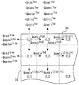
- i and j are used as indexes to distinguish each rectangular element.
- j 1 to NW corresponds to a rectangular element of the first region 31.
- the i-th element from the top and the j-th element from the side surface 30 is referred to as an i_j element (see FIG. 5).
- V i, j the volume of the i_j element.
- Each rectangular element has a unit length in the longitudinal direction of the steel plate.
- V i, j represents a value obtained by dividing the volume of each rectangular element by the unit length in the longitudinal direction of the steel plate. For this reason, V i, j has a unit of area.
- it calculates using the value which divided the calorie
- the first_j element is a rectangular element including the upper surface 34 of the steel plate.
- the volume V 1, j of the first_j element can be calculated by the following equation.
- the (2NT-1) _j element is a rectangular element including the lower surface 35 of the steel plate.
- the volume V 2NT-1, j of the (2NT-1) _j element can be calculated by the following equation.
- FIG. 5 is a diagram schematically showing the heat balance of a rectangular element.
- Various amounts of heat in the heat balance of the rectangular element can be calculated using theoretical formulas used in general heat transfer theory and rolling theory. First, a method for calculating the heat balance of a rectangular element including the upper surface 34 or the lower surface 35 of the steel plate and not including the side surface 30 will be described.
- the thermal radiation amounts Q rad Top and Q rad Bot from the upper surface 34 and the lower surface 35 of the steel sheet can be calculated based on the temperatures of the upper surface 34 and the lower surface 35.
- the amount of heat radiation Q rad Top or Q rad Bot from the upper surface 34 or the lower surface 35 of the rectangular element is obtained. Can be calculated.
- Outlet heat Q water Top and Q water Bot from top 34 and bottom surface 35 of the steel sheet by water cooling can be calculated based on the temperature of the upper surface 34 and lower surface 35, the water temperature, and the heat transfer coefficient.
- the water-cooled outflow heat quantity Q water Top or Q water Bot of the upper surface 34 or the lower surface 35 of the rectangular element is calculated. it can.
- the water-cooled outflow heat amounts Q water Top and Q water Bot of the upper surface 34 and the lower surface 35 of the steel plate are included only in the water-cooled region.
- the water cooling region is a region where the steel sheet is cooled with water.
- the water cooling region includes the high-pressure descaling device 2, the finish entry side descaling device 9, and the run-out laminar spray cooling device 12.
- a finishing mill 10 shown in FIG. 1 includes a plurality of stands.
- a water spray device may be provided between the stands of the finish rolling mill 10.
- the water cooling area includes all areas where the steel sheet is cooled with water, such as a water spray device.
- the amount of heat Q conv Top and Q conv Bot flowing out from the upper surface 34 and the lower surface 35 of the steel sheet by air cooling can be calculated based on the temperature, temperature, and heat transfer coefficient of the upper surface 34 and the lower surface 35.
- the air cooling outflow heat quantities Q conv Top and Q conv Bot of the upper surface 34 and the lower surface 35 of the steel plate are included only in the air cooling region.
- the air-cooling region is a region where the upper surface 34 and the lower surface 35 of the steel plate are cooled in contact with air.
- the amount of heat Q flick Top , Q fric Bot , Q roll Top , Q roll Bot , and Q def in the rolling roll bite are included only in the roll bites of the roughing mill 4 and the finishing mill 10.
- the frictional heat quantities Qfric Top and Qfric Bot in the rolling roll bite can be calculated using the plate speed, the amount of reduction, the friction coefficient, and the like. By multiplying the heat flux of the frictional heat of the upper surface 34 or the lower surface 35 in the roll bite by the length of each rectangular element in the plate width direction, the amount of frictional heat Q fric Top or Q fric of the upper surface 34 or the lower surface 35 of the rectangular element is obtained. Bot can be calculated.
- the amount of heat conduction Q roll Top and Q roll Bot to the roll in the rolling roll bite can be calculated using the temperature and thermal conductivity of the upper surface 34, the lower surface 35, and the roll. By multiplying the heat flux of heat conduction to the roll of the upper surface 34 or the lower surface 35 in the roll bite by the length in the plate width direction of each rectangular element, the heat of the upper surface 34 or the lower surface 35 of the rectangular element to the roll Conductivity Q roll Top or Q roll Bot can be calculated.
- the processing calorific value Q def in the rolling roll bite can be calculated using a reduction amount, material deformation resistance, and the like.
- the processing calorific value Q def in the rolling roll bite can be calculated by distributing the total calorific value to each rectangular element at the ratio of the volume Vi , j of each rectangular element.
- the heating amount Q EH by the edge heater 7 is included only in the edge heater 7.
- the heating amount Q EH by the edge heater 7 is counted only for some of the rectangular elements in the first region 31.
- j EH can be determined based on the heating region of the edge heater 7 (the length in the plate width direction of the portion heated by the edge heater 7).
- the heating amount Q EH by the edge heater 7 can be calculated by distributing the total heating amount to each rectangular element with the ratio of the volume Vi , j of each rectangular element to the target rectangular element group.
- the amount of heat conduction between the rectangular elements can be calculated based on the temperature of both rectangular elements and the thermal conductivity.
- the amount of heat conduction between the rectangular elements in the plate thickness direction (x direction) can be calculated by multiplying the heat flux of heat conduction by the length of the rectangular elements in the plate width direction.
- the amount of heat conduction in the plate width direction (y direction) between the rectangular elements can be calculated by multiplying the heat flux of heat conduction by the length of the rectangular elements in the plate thickness direction.
- the amount of heat conduction from the lower surface 35 of the steel plate to the conveying roller may be further included.
- the amount of thermal radiation Q rad Side from the side surface 30 of the steel plate can be calculated based on the temperature of the side surface 30.
- the heat radiation amount Q rad Side of the side surface 30 of the rectangular element can be calculated.
- Outlet heat Q water Side from the side 30 of the steel sheet by water cooling can be calculated based on the temperature of the side surface 30, the water temperature, and the heat transfer coefficient.
- the water-cooled outflow heat quantity Q water Side of the side surface 30 of the steel plate is included only in the water-cooled region.
- the amount of heat Q conv Side that flows out from the side surface 30 of the steel sheet by air cooling can be calculated based on the temperature, temperature, and heat transfer coefficient of the side surface 30.
- the air cooling outflow heat quantity Q conv Side of the side surface 30 of the steel plate is included only in the air cooling region.
- the present embodiment may be calculated as follows.
- the water-cooled heat flux on the side surface 30 is defined as q water Side [W / mm 2 ], and the water-cooled heat flux on the upper surface 34 is defined as q water Top [W / mm 2 ].
- a predetermined adjustment coefficient larger than zero and smaller than 1 is defined as ⁇ .
- the calculation load can be further reduced by calculating the water cooling outflow heat quantity Q water Side of the side surface 30 using the q water Side calculated by the above formula. Instead of the above calculation, the following may be performed.
- the water-cooling heat transfer coefficient of the side surface 30 is defined as h water Side
- the water-cooling water-cooling heat transfer coefficient of the upper surface 34 is defined as h water Top .
- the first_1 element is a rectangular element including the upper surface 34 and the side surface 30 of the steel plate.
- the heat balance of the first_1 element can be expressed as follows:
- the (2N-1) _1 element is a rectangular element including the lower surface 35 and the side surface 30 of the steel plate.
- the heat balance of the (2N-1) _1th element can be expressed as follows:
- the amount of heat conduction from the side surface 30 of the steel plate to the edger roll of the edger 3 may be further included.
- the temperature calculation unit 100b calculates the temperature change amount of each rectangular element during the time interval ⁇ t by the following equation.
- T i, j k [K] Temperature of the i_j element at time step k
- T i, j k + 1 [K] Temperature of the i_j element at time step (k + 1) after time step ⁇ t.
- the temperature calculation unit 100b calculates the heat balance, the temperature change amount, and the temperature of each rectangular element as described above for each time step ⁇ t using the finite difference method. Thereby, the temperature calculation part 100b can calculate the temperature of each rectangular element in each time step for every time step ⁇ t from the calculation start to the calculation end. By calculating the temperature of each rectangular element, the temperature distribution of the cross section perpendicular to the longitudinal direction of the steel sheet can be obtained.
- the element division part 100a divides
- the volume V i, j of each rectangular element is recalculated.
- the element dividing unit 100a may reduce the number of divisions in the plate thickness direction as the plate thickness of the steel plate is reduced.
- the position where the temperature calculation unit 100b starts the calculation can be, for example, a position where the steel plate (slab) has left the slab heating furnace 1.
- the steel plate (slab) is controlled to be heated to a predetermined temperature.
- the temperature calculation unit 100b may consider that the entire steel plate (slab) is heated to a uniform temperature when leaving the slab heating furnace 1, and may use the predetermined temperature as the initial temperature of each rectangular element.
- the temperature calculation unit 100b may determine the initial temperature of each rectangular element based on the calculation result.
- the position where the temperature calculation unit 100b ends the calculation can be, for example, the position of the fourth thermometer 13 in front of the coiler 14.
- the temperature calculation unit 100b may correct the calculation result based on the surface temperature of the steel plate measured by the first thermometer 5, the second thermometer 6, the third thermometer 11, or the fourth thermometer 13. .
- the temperature of the edge portion of the steel plate in the hot rolling process tends to decrease. Further, when heated by the edge heater 7, the temperature rises only at the edge portion of the steel plate. For this reason, an edge part of a steel plate tends to have a large temperature change and temperature gradient.
- the present embodiment by dividing the first region 31 into a plurality in the plate width direction, the temperature distribution of the edge portion of the steel plate having a large temperature change and temperature gradient can be accurately calculated. In the second region 32, the temperature becomes substantially uniform along the plate width direction. For this reason, the temperature distribution of the steel plate can be accurately calculated without dividing the second region 32 in the plate width direction.
- an increase in the total number of rectangular elements can be suppressed by dividing the second region 32 only in the plate thickness direction without dividing the second region 32 in the plate width direction.
- an increase in calculation load can be suppressed.
- the load on the computer can be sufficiently reduced even in the online control calculation of actual operation.
- the amount of temperature change per time step ⁇ t is approximately equal according to the change in the boundary conditions of the air cooling region, the water cooling region, and the rolling region.
- a method of changing the time step ⁇ t may be used. This method is disclosed in Japanese Patent No. 5391205. According to this method, the number of calculations can be reduced while ensuring the accuracy of the temperature change amount for each time step, and the computer load of the online control calculation in actual operation can be further reduced.
- the surface temperature of the steel sheet does not decrease uniformly due to a change in the boundary condition, and shows a change that repeats a decrease and an increase. Due to the change in the various boundary conditions as described above, the temperature change on the surface of the steel sheet is large. The temperature change inside the steel sheet is relatively gentle because it is mainly due to heat conduction. From these things, the temperature distribution which changes complicatedly arises in the cross section perpendicular
- the state of phase transformation changes according to the temperature history of the steel sheet, and the mechanical properties such as the strength of the final product change. For this reason, it is extremely important to manage the temperature of the steel sheet.
- the temperature of the steel sheet is measured and managed using the first thermometer 5, the second thermometer 6, the third thermometer 11, and the fourth thermometer 13.
- These radiation thermometers provided in the rolling system 20 usually measure the temperature of the central portion of the upper surface 34 of the steel plate in the plate width direction. For this reason, the temperature management of a steel plate is normally performed using the temperature of the center part of a plate width direction. A large difference between the temperature at the center portion in the plate width direction and the temperature at the edge portion is not preferable because only the edge portion has different mechanical properties.
- the temperature distribution of the steel sheet can be accurately calculated including the edge portion.
- the edge heater control unit 100c controls the output or heating amount of the edge heater 7 based on the temperature of each rectangular element calculated by the temperature calculation unit 100b.
- the temperature distribution of the edge portion of the steel plate heated by the edge heater 7 is accurately calculated by dividing the first region 31 including the heating region of the edge heater 7 into a plurality in the plate width direction. it can.
- the output or heating amount of the edge heater 7 is reduced so that the difference between the temperature at the center portion in the plate width direction and the temperature at the edge portion is reduced. It becomes possible to control the heating amount with high accuracy.
- Embodiment 2 the second embodiment of the present invention will be described with reference to FIG. 6 and FIG. 7.
- the description will focus on the differences from the first embodiment described above, and the same or corresponding parts will be denoted by the same reference numerals. The description is omitted.
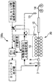
- FIG. 6 is a block diagram of the edge heater control unit 100c of the rolling system 20 according to the second embodiment. In FIG. 6, some of the equipment included in the rolling system 20 in the second embodiment is omitted.
- the edge heater control unit 100c measures a temperature difference between the representative temperature of the second region 32 of the steel sheet and the representative temperature of the first region 31 at a position downstream of the edge heater 7. Execute.
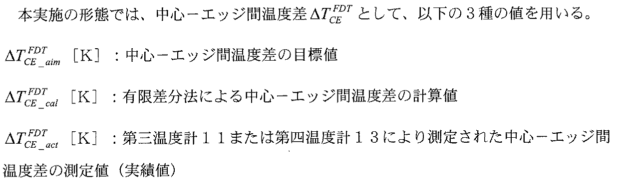
- the temperature difference is hereinafter referred to as “center-edge temperature difference”.
- the representative temperature of the first region 31 corresponds to the representative temperature of the edge portion of the steel plate.
- the representative temperature of the second region 32 corresponds to the representative temperature of the portion other than the edge portion of the steel plate or the representative temperature of the central portion in the plate width direction of the steel plate.
- the edge heater controller 100c executes the step of calculating the temperature difference between the center and the edge using the calculation method based on the finite difference method described in the first embodiment.
- the edge heater control unit 100c executes a step of learning a correction coefficient based on the measured value of the center-edge temperature difference and the calculated value of the center-edge temperature difference.
- the edge heater control unit 100c executes a step of correcting the calculated value of the center-edge temperature difference using the correction coefficient.
- the edge heater control unit 100c A step of controlling the output or heating amount of the heater 7 is executed.
- the edge heater 7 is usually installed between the roughing mill 4 and the finishing mill 10.
- the temperature difference between the center and the edge is measured using the third thermometer 11 or the fourth thermometer 13.
- the scanning radiation thermometer can measure the temperature at a plurality of points in the plate width direction on the upper surface 34 of the steel plate by scanning the measurement points in the plate width direction.
- the third thermometer 11 measures the steel plate temperature on the exit side of the finishing mill 10.
- the fourth thermometer 13 measures the steel plate temperature on the entry side of the coiler 14. At these measurement positions, the steel plate surface is stable and temperature measurement is stable.
- FIG. 7 is a diagram for explaining the measurement position in the plate width direction of the temperature difference between the center and the edge.
- the scanning radiation thermometer measures the temperature at several points defined by the distance from the side surface 30 of the steel sheet and the temperature at the center position in the sheet width direction of the steel sheet.
- the temperature at the center position 36 in the plate width direction of the upper surface 34 of the steel plate is used as the representative temperature of the second region 32 of the steel plate.
- the temperature of the position 37 where the distance from the side surface 30 becomes y E in the upper surface 34 of the steel plate, is used as a representative temperature of the first region 31.
- the temperature of the rectangular element calculated by the finite difference method corresponds to the average temperature in the rectangular element.
- the element dividing unit 100a desirably divides the first region 31 so that the position 37 where the representative temperature of the first region 31 is measured coincides with the center of any rectangular element in the plate width direction. Thereby, the calculated value of the temperature difference between the center and the edge can be obtained more accurately.
- the center in the plate width direction of the E-th rectangular element from the side surface 30 coincides with the position 37 where the representative temperature of the first region 31 is measured.
- E 3
- E may be 4 or more. In this case, the following equation holds.
- T E Cal can be calculated with high accuracy.
- T E Cal can be calculated by the following equation.
- the temperature difference between the center and the edge is expressed by the following equation.
- the calculated value of the representative temperature of the second region 32 corresponds to the calculated value of the temperature of the rectangular element including the upper surface 34 of the second region 32, that is, the first_ (NW + 1) element.
- the calculated value of the temperature of the first_ (NW + 1) element is T 1_NW + 1 [K].
- the edge heater control unit 100c controls the output or heating amount of the edge heater 7 so that the calculated value and the measured value of the center-to-edge temperature difference described above move close to the target value of the center-to-edge temperature difference.
- the target value of the temperature difference between the center and the edge is preferably set to about 20K, for example.
- the method of directly feedback controlling the edge heater 7 based on the measured value of the temperature difference between the center and the edge is the center. -It may not always be easy to bring the measured value of the temperature difference between edges close to the target value.
- the measured value of the temperature difference between the center and the edge is brought close to the target value with high accuracy by controlling the edge heater 7 also using the calculated value of the temperature difference between the center and the edge. Is possible.
- the measured value of the center-to-edge temperature difference can be made closer to the target value with higher accuracy. It becomes possible.
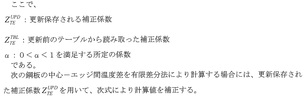
- the correction coefficient ZTE is the ratio between the measured value and the calculated value of the temperature difference between the center and the edge.
- the correction coefficient ZTE is calculated by the following equation.
- correction coefficient ZTE calculated by the above equation is smoothed by the following equation and then updated and stored in a lookup table or the like.
- the learning calculation as described above is continuously repeated for each steel plate. As a result, the accuracy of the calculated value of the temperature difference between the center and the edge can be increased.
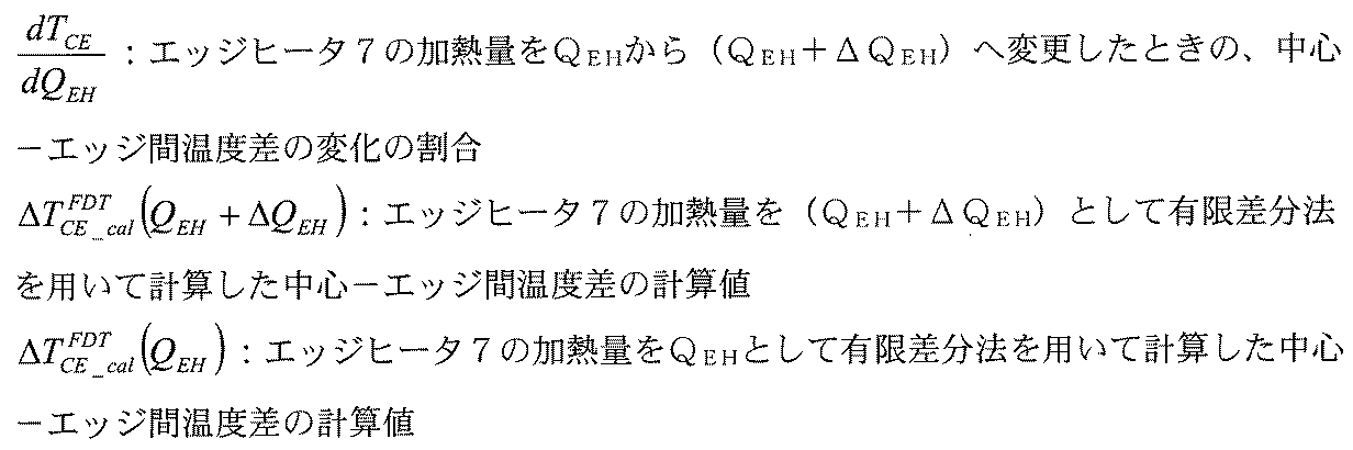
- the change rate of the temperature difference between the center and the edge with respect to the change of the heating amount of the edge heater 7 is calculated by the following equation using the finite difference method. In this calculation, the calculated value is corrected using the correction coefficient described above.
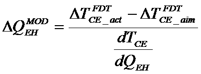
- a correction amount ⁇ Q EH MOD of the heating amount of the edge heater 7 necessary for eliminating the deviation between the measured value of the center-edge temperature difference and the target value is calculated by the following equation.
- the edge heater control unit 100c controls the output or heating amount of the edge heater 7 based on the correction amount ⁇ Q EH MOD calculated by the above formula. For example, the edge heater control unit 100c corrects the output or heating amount of the edge heater 7 that heats the next steel plate using the following equation.
- the edge heater control unit 100c transmits to the edge heater 7 a signal for controlling the output or heating amount of the edge heater 7 so that the heating amount of the edge heater 7 that heats the next steel plate is corrected as described above. Moreover, it is desirable that the edge heater control unit 100c updates the look-up table of the heating amount of the edge heater 7 based on the heating amount of the edge heater 7 corrected as described above.
- the measured value (actual value) of the temperature difference between the center and the edge can be brought close to the target value with high accuracy.
- the difference of the temperature of the center part of the board width direction of a steel plate and the temperature of an edge part can be made small more reliably. As a result, the quality of the steel sheet can be further increased including the edge portion.
Landscapes
- Chemical & Material Sciences (AREA)
- Engineering & Computer Science (AREA)
- Mechanical Engineering (AREA)
- Physics & Mathematics (AREA)
- Thermal Sciences (AREA)
- Crystallography & Structural Chemistry (AREA)
- Materials Engineering (AREA)
- Metallurgy (AREA)
- Organic Chemistry (AREA)
- Control Of Metal Rolling (AREA)
Abstract
Description
図1は、本発明の実施の形態1が適用される圧延システムを示す構成図である。図1に示す圧延システム20は、スラブ加熱炉1、高圧デスケーリング装置2、エッジャー3、粗圧延機4、第一温度計5、第二温度計6、エッジヒータ7、クロップシャー8、仕上入側デスケーリング装置9、仕上圧延機10、第三温度計11、ランアウトラミナースプレー冷却装置12、第四温度計13、コイラー14、及び制御装置100を備える。圧延システム20により熱間圧延される鋼板は、鋼板の長手方向(図1中の横方向)に搬送される。鋼板の長手方向及び板厚方向の双方に垂直な方向が板幅方向である。鋼板の板幅は、例えば900mm~2000mm程度である。圧延される前の鋼板(スラブ)の板厚は、例えば200mm~250mm程度である。仕上圧延機10を出た鋼板の板厚は、例えば1mm~25mm程度である。
ΔyNW+1=B-2*(Δy1+Δy2+Δy3+・・・+ΔyNW)





qwater Side=β*qwater Top
hwater Side=β*hwater Top
上記の式で計算したhwater Sideを用いて側面30の水冷の熱流束を計算し、その熱流束を用いて側面30の水冷の流出熱量Qwater Sideを計算することで、上記と類似の効果が得られる。





Ti,j k+1=Ti,j k+ΔTi,j
Ti,j k[K]:時間ステップkにおける第i_j要素の温度
Ti,j k+1[K]:時間刻みΔt後の時間ステップ(k+1)における第i_j要素の温度
である。
次に、図6及び図7を参照して、本発明の実施の形態2について説明するが、上述した実施の形態1との相違点を中心に説明し、同一部分または相当部分は同一符号を付し説明を省略する。


jE=E
である。



ΔTCE_cal FDT=T1_NW+1-TE Cal






Claims (12)
- 熱間圧延される鋼板の長手方向に対して垂直な断面を複数の矩形要素に分割すること、及び
有限差分法を用いて前記矩形要素の各々の温度を計算すること、
を含み、
前記断面のエッジ部を含む領域である第一領域は、複数の前記矩形要素が板厚方向に並ぶとともに複数の前記矩形要素に板幅方向に並ぶように分割され、
前記断面の中心を含み、前記第一領域より広い領域である第二領域は、複数の前記矩形要素が板厚方向に並ぶように分割され、前記板幅方向には分割されない温度計算方法。 - 前記第二領域に近い位置から前記鋼板の側面に近づくにつれて、前記第一領域の前記矩形要素の前記板幅方向の長さが小さくなる請求項1に記載の温度計算方法。
- 前記鋼板が水冷されるときの前記有限差分法の計算において、前記鋼板の上面の水冷による熱流束または熱伝達係数の値に、ゼロより大きく1より小さい調整係数を乗じた値を、前記鋼板の側面の水冷による熱流束または熱伝達係数の値として用いる請求項1または請求項2に記載の温度計算方法。
- 前記第一領域は、前記鋼板のエッジ部を加熱するエッジヒータの加熱領域を包含する請求項1から請求項3のいずれか一項に記載の温度計算方法。
- 前記鋼板のエッジ部を加熱するエッジヒータより下流側の位置において、前記第二領域の代表温度と、前記第一領域の代表温度との温度差を測定すること、
請求項1から請求項4のいずれか一項に記載の温度計算方法を用いて、前記温度差を計算すること、及び
前記温度差の測定値と、前記温度差の計算値と、前記温度差の目標値とに基づいて、前記エッジヒータの出力または加熱量を制御すること、
を含む加熱制御方法。 - 前記測定値及び前記計算値に基づいて補正係数を学習すること、及び
前記補正係数で前記計算値を補正すること、
を含む請求項5に記載の加熱制御方法。 - 熱間圧延される鋼板の長手方向に対して垂直な断面を複数の矩形要素に分割する手段と、
有限差分法を用いて前記矩形要素の各々の温度を計算する手段と、
を備え、
前記断面のエッジ部を含む領域である第一領域は、複数の前記矩形要素が板厚方向に並ぶとともに複数の前記矩形要素に板幅方向に並ぶように分割され、
前記断面の中心を含み、前記第一領域より広い領域である第二領域は、複数の前記矩形要素が板厚方向に並ぶように分割され、前記板幅方向には分割されない温度計算装置。 - 前記第二領域に近い位置から前記鋼板の側面に近づくにつれて、前記第一領域の前記矩形要素の前記板幅方向の長さが小さくなる請求項7に記載の温度計算装置。
- 前記鋼板が水冷されるときの前記有限差分法の計算において、前記鋼板の上面の水冷による熱流束または熱伝達係数の値に、ゼロより大きく1より小さい調整係数を乗じた値を、前記鋼板の側面の水冷による熱流束または熱伝達係数の値として用いる請求項7または請求項8に記載の温度計算装置。
- 前記第一領域は、前記鋼板のエッジ部を加熱するエッジヒータの加熱領域を包含する請求項7から請求項9のいずれか一項に記載の温度計算装置。
- 請求項7から請求項10のいずれか一項に記載の温度計算装置と、
前記鋼板のエッジ部を加熱するエッジヒータより下流側の位置において、前記第二領域の代表温度と、前記第一領域の代表温度との温度差を測定する手段と、
前記温度計算装置を用いて、前記温度差を計算する手段と、
前記温度差の測定値と、前記温度差の計算値と、前記温度差の目標値とに基づいて、前記エッジヒータの出力または加熱量を制御する手段と、
を備える加熱制御装置。 - 前記測定値及び前記計算値に基づいて補正係数を学習する手段と、
前記補正係数で前記計算値を補正する手段と、
を備える請求項11に記載の加熱制御装置。
Priority Applications (5)
| Application Number | Priority Date | Filing Date | Title |
|---|---|---|---|
| CN201580078217.7A CN107405657B (zh) | 2015-03-26 | 2015-03-26 | 温度计算方法、温度计算装置、加热控制方法、以及加热控制装置 |
| KR1020177026501A KR102032039B1 (ko) | 2015-03-26 | 2015-03-26 | 온도 계산 방법, 온도 계산 장치, 가열 제어 방법, 및 가열 제어 장치 |
| US15/557,918 US10710133B2 (en) | 2015-03-26 | 2015-03-26 | Temperature calculation method, temperature calculation apparatus, heating control method, and heating control apparatus |
| PCT/JP2015/059433 WO2016151854A1 (ja) | 2015-03-26 | 2015-03-26 | 温度計算方法、温度計算装置、加熱制御方法、及び加熱制御装置 |
| JP2017507293A JP6447710B2 (ja) | 2015-03-26 | 2015-03-26 | 温度計算方法、温度計算装置、加熱制御方法、及び加熱制御装置 |
Applications Claiming Priority (1)
| Application Number | Priority Date | Filing Date | Title |
|---|---|---|---|
| PCT/JP2015/059433 WO2016151854A1 (ja) | 2015-03-26 | 2015-03-26 | 温度計算方法、温度計算装置、加熱制御方法、及び加熱制御装置 |
Publications (1)
| Publication Number | Publication Date |
|---|---|
| WO2016151854A1 true WO2016151854A1 (ja) | 2016-09-29 |
Family
ID=56977168
Family Applications (1)
| Application Number | Title | Priority Date | Filing Date |
|---|---|---|---|
| PCT/JP2015/059433 Ceased WO2016151854A1 (ja) | 2015-03-26 | 2015-03-26 | 温度計算方法、温度計算装置、加熱制御方法、及び加熱制御装置 |
Country Status (5)
| Country | Link |
|---|---|
| US (1) | US10710133B2 (ja) |
| JP (1) | JP6447710B2 (ja) |
| KR (1) | KR102032039B1 (ja) |
| CN (1) | CN107405657B (ja) |
| WO (1) | WO2016151854A1 (ja) |
Families Citing this family (9)
| Publication number | Priority date | Publication date | Assignee | Title |
|---|---|---|---|---|
| CN108356082B (zh) * | 2018-03-20 | 2019-01-22 | 西安科技大学 | 孔型轧机加工温度实时监测记录与误差校正方法 |
| DE102019203088A1 (de) * | 2019-03-06 | 2020-09-10 | Sms Group Gmbh | Verfahren zur Herstellung eines metallischen Bandes oder Blechs |
| TWI697561B (zh) * | 2019-06-05 | 2020-07-01 | 中國鋼鐵股份有限公司 | 轉爐之底吹孔之熔損的評估方法 |
| CN112404323B (zh) * | 2020-11-18 | 2022-05-24 | 攀钢集团攀枝花钢铁研究院有限公司 | 板坯加热炉控制系统及方法 |
| CN114570776B (zh) * | 2020-11-30 | 2024-08-16 | 宝山钢铁股份有限公司 | 一种车底式加热炉出炉板坯全长温度均匀性的控制方法 |
| JP7111217B1 (ja) * | 2021-04-30 | 2022-08-02 | Jfeスチール株式会社 | 冷延鋼板の製造方法及び製造設備 |
| JP7111216B1 (ja) * | 2021-04-30 | 2022-08-02 | Jfeスチール株式会社 | 冷延鋼板の製造方法及び製造設備 |
| TWI785975B (zh) * | 2022-01-26 | 2022-12-01 | 中國鋼鐵股份有限公司 | 精軋機之溫度控制方法 |
| CN115254994B (zh) * | 2022-08-24 | 2024-09-03 | 重庆钢铁股份有限公司 | 一种钛板轧制吹扫方法、装置、设备及存储介质 |
Citations (3)
| Publication number | Priority date | Publication date | Assignee | Title |
|---|---|---|---|---|
| JP2001269702A (ja) * | 2000-03-27 | 2001-10-02 | Kawasaki Steel Corp | 熱間鋼材の温度推定方法 |
| JP2009233725A (ja) * | 2008-03-28 | 2009-10-15 | Jfe Steel Corp | 熱間粗圧延における被圧延材の温度予測方法および熱延金属帯の製造方法 |
| JP2012148310A (ja) * | 2011-01-19 | 2012-08-09 | Jfe Steel Corp | 鋼板エッジ部の加熱方法 |
Family Cites Families (9)
| Publication number | Priority date | Publication date | Assignee | Title |
|---|---|---|---|---|
| IT1065046B (it) | 1976-12-13 | 1985-02-25 | Pirelli | Cerchietto per tallone di pneumatico tipo tubeless e pneumatico relativo |
| DE19639062A1 (de) * | 1996-09-16 | 1998-03-26 | Mannesmann Ag | Modellgestütztes Verfahren zur kontrollierten Kühlung von Warmband oder Grobblech in einem rechnergeführten Walz- und Kühlprozeß |
| DE102008011303B4 (de) * | 2008-02-27 | 2013-06-06 | Siemens Aktiengesellschaft | Betriebsverfahren für eine Kühlstrecke zum Kühlen eines Walzguts mit von der Temperatur losgelöster Kühlung auf einen Endenthalpiewert |
| US8935945B2 (en) * | 2008-11-19 | 2015-01-20 | Toshiba Mitsubishi-Electic Industrial Systems Corporation | Control system |
| CN101456038B (zh) * | 2009-01-08 | 2012-01-04 | 上海交通大学 | 热轧带钢层流冷却过程板带温度监测方法 |
| WO2011040622A1 (ja) * | 2009-09-30 | 2011-04-07 | Jfeスチール株式会社 | 低降伏比、高強度および高一様伸びを有した鋼板及びその製造方法 |
| CN102821885B (zh) * | 2010-04-09 | 2014-12-31 | 东芝三菱电机产业系统株式会社 | 轧制材料冷却控制装置、轧制材料冷却控制方法、轧制材料冷却控制程序 |
| CN103433295B (zh) * | 2013-08-05 | 2016-08-10 | 苏州有色金属研究院有限公司 | 单机架双卷取铝热轧机凸度控制方法 |
| CN103761370B (zh) * | 2014-01-03 | 2017-08-25 | 东北大学 | 一种板带热轧过程表面换热系数的预测方法 |
-
2015
- 2015-03-26 CN CN201580078217.7A patent/CN107405657B/zh active Active
- 2015-03-26 JP JP2017507293A patent/JP6447710B2/ja active Active
- 2015-03-26 KR KR1020177026501A patent/KR102032039B1/ko active Active
- 2015-03-26 WO PCT/JP2015/059433 patent/WO2016151854A1/ja not_active Ceased
- 2015-03-26 US US15/557,918 patent/US10710133B2/en active Active
Patent Citations (3)
| Publication number | Priority date | Publication date | Assignee | Title |
|---|---|---|---|---|
| JP2001269702A (ja) * | 2000-03-27 | 2001-10-02 | Kawasaki Steel Corp | 熱間鋼材の温度推定方法 |
| JP2009233725A (ja) * | 2008-03-28 | 2009-10-15 | Jfe Steel Corp | 熱間粗圧延における被圧延材の温度予測方法および熱延金属帯の製造方法 |
| JP2012148310A (ja) * | 2011-01-19 | 2012-08-09 | Jfe Steel Corp | 鋼板エッジ部の加熱方法 |
Also Published As
| Publication number | Publication date |
|---|---|
| CN107405657A (zh) | 2017-11-28 |
| US10710133B2 (en) | 2020-07-14 |
| JP6447710B2 (ja) | 2019-01-09 |
| KR20170119699A (ko) | 2017-10-27 |
| JPWO2016151854A1 (ja) | 2017-11-30 |
| US20180043407A1 (en) | 2018-02-15 |
| CN107405657B (zh) | 2019-03-19 |
| KR102032039B1 (ko) | 2019-10-14 |
Similar Documents
| Publication | Publication Date | Title |
|---|---|---|
| JP6447710B2 (ja) | 温度計算方法、温度計算装置、加熱制御方法、及び加熱制御装置 | |
| US10040107B2 (en) | Temperature control apparatus of hot-rolling mill | |
| TWI224144B (en) | Heat treating device, heat treating method, recording medium recording heat treating program and steel product | |
| JP5391205B2 (ja) | 制御装置 | |
| CN104271277B (zh) | 温度控制装置 | |
| JP5565200B2 (ja) | 熱間圧延における仕上温度制御装置 | |
| JP6146553B1 (ja) | 鋼板の温度制御装置及び温度制御方法 | |
| KR101821089B1 (ko) | 압연 시스템 | |
| WO2017130508A1 (ja) | 鋼板の温度制御装置及び温度制御方法 | |
| JP6558060B2 (ja) | 厚鋼板の冷却制御方法、冷却制御装置、製造方法、および、製造装置 | |
| JP5493993B2 (ja) | 厚鋼板の冷却制御装置、冷却制御方法、及び、製造方法 | |
| KR101592741B1 (ko) | 온도 분포 예측 장치 | |
| JP2017164808A (ja) | 鋼板の残留応力推定方法および鋼板の製造方法ならびに鋼板の残留応力推定装置および鋼板の製造設備 | |
| JP6874730B2 (ja) | 熱間圧延ライン制御装置 | |
| KR102230316B1 (ko) | 에지 히터 제어 장치 | |
| JP6645036B2 (ja) | 厚鋼板の冷却制御方法、冷却制御装置、製造方法、および、製造装置 | |
| JP6627609B2 (ja) | 冷却制御方法及び冷却装置 | |
| JP2019155372A (ja) | 厚鋼板冷却方法 | |
| JP4258341B2 (ja) | 鋼板長手方向の材質均一性に優れた高強度鋼板の製造方法 | |
| JP4714658B2 (ja) | 鋼材の加熱方法 | |
| JP6645037B2 (ja) | 厚鋼板の冷却制御方法、冷却制御装置、製造方法、および、製造装置 | |
| JP5741634B2 (ja) | 熱延鋼板の冷却制御方法及び装置 | |
| JP2001300613A (ja) | 熱間仕上圧延機のセットアップ方法 | |
| JP2002137013A (ja) | 鋼板の冷却条件設定方法 |
Legal Events
| Date | Code | Title | Description |
|---|---|---|---|
| 121 | Ep: the epo has been informed by wipo that ep was designated in this application |
Ref document number: 15886406 Country of ref document: EP Kind code of ref document: A1 |
|
| ENP | Entry into the national phase |
Ref document number: 2017507293 Country of ref document: JP Kind code of ref document: A |
|
| WWE | Wipo information: entry into national phase |
Ref document number: 15557918 Country of ref document: US |
|
| ENP | Entry into the national phase |
Ref document number: 20177026501 Country of ref document: KR Kind code of ref document: A |
|
| NENP | Non-entry into the national phase |
Ref country code: DE |
|
| 122 | Ep: pct application non-entry in european phase |
Ref document number: 15886406 Country of ref document: EP Kind code of ref document: A1 |