WO2016148021A1 - 透明液吐出量決定装置及び方法、並びに画像形成装置及び方法 - Google Patents
透明液吐出量決定装置及び方法、並びに画像形成装置及び方法 Download PDFInfo
- Publication number
- WO2016148021A1 WO2016148021A1 PCT/JP2016/057599 JP2016057599W WO2016148021A1 WO 2016148021 A1 WO2016148021 A1 WO 2016148021A1 JP 2016057599 W JP2016057599 W JP 2016057599W WO 2016148021 A1 WO2016148021 A1 WO 2016148021A1
- Authority
- WO
- WIPO (PCT)
- Prior art keywords
- transparent liquid
- ink
- amount
- discharge amount
- unit
- Prior art date
- Legal status (The legal status is an assumption and is not a legal conclusion. Google has not performed a legal analysis and makes no representation as to the accuracy of the status listed.)
- Ceased
Links
Images


Classifications
-
- B—PERFORMING OPERATIONS; TRANSPORTING
- B41—PRINTING; LINING MACHINES; TYPEWRITERS; STAMPS
- B41J—TYPEWRITERS; SELECTIVE PRINTING MECHANISMS, i.e. MECHANISMS PRINTING OTHERWISE THAN FROM A FORME; CORRECTION OF TYPOGRAPHICAL ERRORS
- B41J11/00—Devices or arrangements of selective printing mechanisms, e.g. ink-jet printers or thermal printers, for supporting or handling copy material in sheet or web form
- B41J11/0015—Devices or arrangements of selective printing mechanisms, e.g. ink-jet printers or thermal printers, for supporting or handling copy material in sheet or web form for treating before, during or after printing or for uniform coating or laminating the copy material before or after printing
-
- B—PERFORMING OPERATIONS; TRANSPORTING
- B41—PRINTING; LINING MACHINES; TYPEWRITERS; STAMPS
- B41J—TYPEWRITERS; SELECTIVE PRINTING MECHANISMS, i.e. MECHANISMS PRINTING OTHERWISE THAN FROM A FORME; CORRECTION OF TYPOGRAPHICAL ERRORS
- B41J2/00—Typewriters or selective printing mechanisms characterised by the printing or marking process for which they are designed
- B41J2/005—Typewriters or selective printing mechanisms characterised by the printing or marking process for which they are designed characterised by bringing liquid or particles selectively into contact with a printing material
- B41J2/01—Ink jet
- B41J2/015—Ink jet characterised by the jet generation process
- B41J2/04—Ink jet characterised by the jet generation process generating single droplets or particles on demand
- B41J2/045—Ink jet characterised by the jet generation process generating single droplets or particles on demand by pressure, e.g. electromechanical transducers
- B41J2/04501—Control methods or devices therefor, e.g. driver circuits, control circuits
- B41J2/04558—Control methods or devices therefor, e.g. driver circuits, control circuits detecting presence or properties of a dot on paper
-
- B—PERFORMING OPERATIONS; TRANSPORTING
- B41—PRINTING; LINING MACHINES; TYPEWRITERS; STAMPS
- B41J—TYPEWRITERS; SELECTIVE PRINTING MECHANISMS, i.e. MECHANISMS PRINTING OTHERWISE THAN FROM A FORME; CORRECTION OF TYPOGRAPHICAL ERRORS
- B41J2/00—Typewriters or selective printing mechanisms characterised by the printing or marking process for which they are designed
- B41J2/005—Typewriters or selective printing mechanisms characterised by the printing or marking process for which they are designed characterised by bringing liquid or particles selectively into contact with a printing material
- B41J2/01—Ink jet
- B41J2/135—Nozzles
- B41J2/165—Prevention or detection of nozzle clogging, e.g. cleaning, capping or moistening for nozzles
- B41J2/16585—Prevention or detection of nozzle clogging, e.g. cleaning, capping or moistening for nozzles for paper-width or non-reciprocating print heads
-
- B—PERFORMING OPERATIONS; TRANSPORTING
- B41—PRINTING; LINING MACHINES; TYPEWRITERS; STAMPS
- B41J—TYPEWRITERS; SELECTIVE PRINTING MECHANISMS, i.e. MECHANISMS PRINTING OTHERWISE THAN FROM A FORME; CORRECTION OF TYPOGRAPHICAL ERRORS
- B41J2/00—Typewriters or selective printing mechanisms characterised by the printing or marking process for which they are designed
- B41J2/005—Typewriters or selective printing mechanisms characterised by the printing or marking process for which they are designed characterised by bringing liquid or particles selectively into contact with a printing material
- B41J2/01—Ink jet
- B41J2/21—Ink jet for multi-colour printing
- B41J2/2107—Ink jet for multi-colour printing characterised by the ink properties
- B41J2/2114—Ejecting specialized liquids, e.g. transparent or processing liquids
-
- B—PERFORMING OPERATIONS; TRANSPORTING
- B41—PRINTING; LINING MACHINES; TYPEWRITERS; STAMPS
- B41J—TYPEWRITERS; SELECTIVE PRINTING MECHANISMS, i.e. MECHANISMS PRINTING OTHERWISE THAN FROM A FORME; CORRECTION OF TYPOGRAPHICAL ERRORS
- B41J2/00—Typewriters or selective printing mechanisms characterised by the printing or marking process for which they are designed
- B41J2/005—Typewriters or selective printing mechanisms characterised by the printing or marking process for which they are designed characterised by bringing liquid or particles selectively into contact with a printing material
- B41J2/01—Ink jet
- B41J2/21—Ink jet for multi-colour printing
- B41J2/2132—Print quality control characterised by dot disposition, e.g. for reducing white stripes or banding
- B41J2/2146—Print quality control characterised by dot disposition, e.g. for reducing white stripes or banding for line print heads
-
- B—PERFORMING OPERATIONS; TRANSPORTING
- B41—PRINTING; LINING MACHINES; TYPEWRITERS; STAMPS
- B41J—TYPEWRITERS; SELECTIVE PRINTING MECHANISMS, i.e. MECHANISMS PRINTING OTHERWISE THAN FROM A FORME; CORRECTION OF TYPOGRAPHICAL ERRORS
- B41J2/00—Typewriters or selective printing mechanisms characterised by the printing or marking process for which they are designed
- B41J2/005—Typewriters or selective printing mechanisms characterised by the printing or marking process for which they are designed characterised by bringing liquid or particles selectively into contact with a printing material
- B41J2/01—Ink jet
- B41J2/135—Nozzles
- B41J2/165—Prevention or detection of nozzle clogging, e.g. cleaning, capping or moistening for nozzles
- B41J2/16505—Caps, spittoons or covers for cleaning or preventing drying out
- B41J2/16508—Caps, spittoons or covers for cleaning or preventing drying out connected with the printer frame
-
- B—PERFORMING OPERATIONS; TRANSPORTING
- B41—PRINTING; LINING MACHINES; TYPEWRITERS; STAMPS
- B41J—TYPEWRITERS; SELECTIVE PRINTING MECHANISMS, i.e. MECHANISMS PRINTING OTHERWISE THAN FROM A FORME; CORRECTION OF TYPOGRAPHICAL ERRORS
- B41J25/00—Actions or mechanisms not otherwise provided for
- B41J2025/008—Actions or mechanisms not otherwise provided for comprising a plurality of print heads placed around a drum
Definitions
- the present invention relates to a transparent liquid discharge amount determining apparatus and method, and an image forming apparatus and method, and in particular, a technique for determining a discharge amount of a transparent liquid when discharging a transparent liquid from a liquid discharge apparatus, and image formation using the transparent liquid.
- a transparent liquid discharge amount determining apparatus and method and an image forming apparatus and method, and in particular, a technique for determining a discharge amount of a transparent liquid when discharging a transparent liquid from a liquid discharge apparatus, and image formation using the transparent liquid.
- the clear liquid used to suppress deformation of the paper must be applied to areas that do not apply much ink to the paper (low image density areas) and non-printing areas, that is, areas where there is no image.
- the low image density region and the non-printing region that need to be applied with the transparent liquid are represented by the term “non-printing region”.
- a liquid application method that applies liquid uniformly to a sheet such as roller application, it is difficult to selectively apply a transparent liquid to a non-printing area. Therefore, as a means for applying the transparent liquid, a configuration using a liquid ejection device that can easily control selective application of the transparent liquid to the non-printing area, such as an ink jet method, is preferable.
- the main purpose of the transparent liquid used to suppress the deformation of the paper is to reduce the deformation of the paper. Therefore, it is preferable that there is almost no change in the appearance of the non-printing area to which the transparent liquid is applied, that is, the visual effect on the appearance of the transparent liquid applying area is substantially unchanged depending on the presence or absence of the transparent liquid.
- the actual ejected amount of liquid may deviate from a predetermined target value assumed in advance.
- a predetermined target value assumed in advance.
- the ejection characteristics of individual nozzles may be different, or ejection failure may occur in some nozzles. May deviate from the value.
- the description of “correcting” the discharge amount includes concepts such as adjusting the discharge amount and performing processing and control for optimizing the discharge amount.
- the present invention has been made in view of such circumstances, and a transparent liquid discharge amount determining apparatus and method that can correct the discharge amount of a transparent liquid discharged by a liquid discharge apparatus by a simple method, and image formation.
- An object is to provide an apparatus and method.
- a transparent liquid discharge amount determining apparatus is a test pattern printed using an ink discharge means for discharging ink containing a color material and a transparent liquid discharge means for discharging a transparent liquid, the ink and transparent Each of the liquids is applied to different areas of the same medium, and the amount of deformation of the test pattern in which the ink application area to which the ink is applied and the transparent liquid application area to which the transparent liquid is applied are arranged next to each other is determined.
- a transparent comprising: information acquisition means for acquiring information to be expressed; and information processing means for determining a discharge amount of the transparent liquid by the transparent liquid discharge means for discharging the transparent liquid from information indicating the medium deformation amount acquired by the information acquisition means. It is a liquid discharge amount determination apparatus.
- the medium deformation amount of the test printed matter on which the test pattern is printed reflects the excess and deficiency of the transparent liquid discharge amount.
- the amount of the transparent liquid discharge amount can be grasped from the information indicating the medium deformation amount of the test pattern, and the adjustment of the transparent liquid discharge amount can be easily performed. Can do.
- the ink application area and the transparent liquid application area are adjacent is not limited to the ink application area and the transparent liquid application area being in contact with each other, and there is a slight gap between the ink application area and the transparent liquid application area. There may be.
- the transparent liquid ejection means includes a nozzle row in which a plurality of nozzles are arranged at different positions in the first direction, and the test pattern is perpendicular to the first direction of the medium.
- a stripe-shaped ink application region extending in the second direction, and a stripe-shaped transparent liquid application region extending in the second direction, wherein the transparent liquid application region and the ink application region are in the first direction. Can be arranged next to each other.
- the signal-to-noise ratio (S / N ratio) can be increased with respect to the measurement of the medium deformation amount, and the measurement result is stabilized.
- each of the ink discharge means and the transparent liquid discharge means includes a plurality of head modules that discharge ink droplets by an ink jet method.
- N is an integer of 1 or more
- each of the stripes of the plurality of transparent liquid application regions to which the transparent liquid is applied is formed by droplet ejection from the N head modules constituting the transparent liquid discharge means. It can be set as a structure.
- the third aspect it is possible to adjust the variation in the discharge amount for each of the head modules constituting the transparent liquid discharge means.
- the test pattern includes a plurality of ink application areas, and the transparent liquid application area includes a plurality of ink application areas. It can be set as the structure arrange
- the signal-to-noise ratio increases with respect to the measurement of the medium deformation amount.
- the discharge amount of the transparent liquid with respect to each region of the plurality of transparent liquid application regions is the medium deformation amount of the transparent liquid application region corresponding to the region of interest, It is determined based on the medium deformation amount of the ink application area on both sides of the area of interest, and the information processing means increases the transparency of the area of interest as the medium deformation amount of the transparent liquid application area corresponding to the area of interest increases. It is possible to reduce the liquid discharge amount and to increase the amount of transparent liquid discharge in the region of interest as the medium deformation amount in the ink application region on both sides of the region of interest increases.
- the algorithm for determining the discharge amount of the transparent liquid can be simplified.
- the number of test prints that are test pattern prints can be reduced.
- the apparatus includes a deformation measurement unit that measures a deformation amount of the test printed matter on which the test pattern is printed, and the information acquisition unit includes The information representing the medium deformation amount can be obtained from the deformation amount measured by the deformation measuring means.
- the information processing means sets a correction value for correcting the discharge amount of the transparent liquid from information representing the medium deformation amount.
- the correction value calculation means to be calculated can be included.
- a plurality of test prints are performed with different discharge amounts of the transparent liquid to the transparent liquid application region in the test pattern.
- the information acquisition means acquires information representing the medium deformation amount for each of the plurality of test prints, and the information processing means performs medium deformation based on the information representing the medium deformation amount obtained from each of the plurality of test prints.
- the value of the discharge amount of the transparent liquid with the smallest amount can be determined as the discharge amount of the transparent liquid.
- the convergence of the result of the algorithm for determining the discharge amount of the transparent liquid can be accelerated.
- the information processing means is a transparent that defines the relationship between the ink amount per unit area and the discharge amount of the transparent liquid.
- the liquid discharge amount determination table may include a transparent liquid discharge amount determination table changing unit that changes the determined value of the transparent liquid discharge amount.
- a transparent liquid discharge amount determination method is a test pattern printed using an ink discharge unit that discharges ink containing a color material and a transparent liquid discharge unit that discharges a transparent liquid. Each of the liquids is applied to different areas of the same medium, and the amount of deformation of the test pattern in which the ink application area to which the ink is applied and the transparent liquid application area to which the transparent liquid is applied are arranged next to each other is determined.
- a transparent process including an information acquisition process for acquiring information to be expressed, and an information processing process for determining a discharge amount of the transparent liquid by the transparent liquid discharge means for discharging the transparent liquid from the information indicating the medium deformation amount acquired by the information acquisition process. This is a liquid discharge amount determination method.
- a test pattern printing step of printing a test pattern using an ink discharge means and a transparent liquid discharge means can be employed.
- the same matters as those specified in the second aspect to the ninth aspect can be appropriately combined.
- the means responsible for the process and function specified in the transparent liquid discharge amount determination device can be grasped as an element of the “process (step)” of the corresponding process and operation.
- An image forming apparatus includes an ink discharge unit that discharges ink containing a color material, a transparent liquid discharge unit that discharges a transparent liquid, an ink discharge unit, and a transparent liquid discharge unit.
- Test pattern printing control means for outputting a test pattern in which a transparent liquid is applied to different areas of the same medium, and an ink application area to which ink is applied and a transparent liquid application area to which the transparent liquid is applied are arranged side by side
- an information acquisition unit for acquiring information representing the medium deformation amount of the test pattern, and an information processing unit for determining the discharge amount of the transparent liquid from the information representing the medium deformation amount acquired by the information acquisition unit.
- the twelfth aspect it is possible to appropriately adjust the discharge amount of the transparent liquid applied to the medium, and it is possible to obtain a good printed matter with less paper deformation.
- An image forming method is a step of printing a test pattern using an ink discharge unit that discharges ink containing a color material and a transparent liquid discharge unit that discharges a transparent liquid.
- a test pattern printing step for printing a test pattern in which an ink application region to which ink is applied and a transparent liquid application region to which a transparent liquid is applied are arranged adjacent to each other in different regions of the same medium; and a test pattern
- ink is discharged by the ink discharge means based on the print data, and the transparent liquid discharge means discharges the transparent liquid according to the determined transparent liquid discharge amount.
- the image forming method comprising an image forming step of performing printing by.
- the thirteenth aspect it is possible to appropriately adjust the discharge amount of the transparent liquid applied to the medium, and it is possible to obtain a good printed matter with less paper deformation.
- the same matters as those specified in the second to ninth aspects can be appropriately combined.
- the means responsible for the process and function specified in the transparent liquid discharge amount determination device can be grasped as an element of the “process (step)” of the corresponding process and operation.
- the discharge amount of the transparent liquid can be corrected by a simple method.
- FIG. 1 is a configuration diagram of an inkjet printing apparatus according to an embodiment.
- FIG. 2 is a perspective view of the inkjet head bar.
- FIG. 3 is a partially enlarged view of the inkjet head bar as seen from the nozzle surface side.
- FIG. 4 is a plan view of the nozzle surface of the head module as viewed from the ejection side.
- FIG. 5 is a longitudinal sectional view showing a three-dimensional structure of one ejector in the head module.
- FIG. 6 is a flowchart showing the flow of the correction process of the transparent liquid discharge amount.
- FIG. 7 is a diagram illustrating an example of a test pattern.
- FIG. 8A is a diagram showing another example of a test pattern.
- FIG. 8B is a diagram showing another example of the test pattern.
- FIG. 9 is an explanatory diagram illustrating the relationship between the stripe width and the head module in the test pattern.
- FIG. 10 is an explanatory diagram showing another example of the relationship between the stripe width and the head module in the test pattern.
- FIG. 11 is an explanatory diagram for automatically reading the degree of paper deformation in a printed test pattern.
- FIG. 12 is a diagram showing an example of the shape profile of the irregularities on the paper surface.
- FIG. 13 is a diagram showing an example of the sheet deformation amount at each position shown in FIG.
- FIG. 14 is an explanatory diagram showing an example in which five types of test patterns with different discharge levels of the transparent liquid are printed.
- FIG. 15 is a graph showing the sheet deformation amount for each transparent liquid discharge amount level at a specific position.
- FIG. 16 is an explanatory view showing an example of a transparent liquid discharge amount determination table.
- FIG. 17 is an explanatory view showing another example of the transparent liquid discharge amount determination table.
- FIG. 18 is an explanatory view showing another example of the transparent liquid discharge amount determination table.
- 19 is an explanatory view showing another example of the transparent liquid discharge amount determination table.
- FIG. 20 is a flowchart of the determination process of the transparent liquid discharge amount at the time of printing based on the print data.
- FIG. 21 is a conceptual diagram in a case where an image, which is ink amount data, is divided into areas having a unit area size.
- FIG. 22 is an explanatory diagram of a process for determining the transparent liquid application amount of the region of interest in the image to be printed.
- FIG. 22 is an explanatory diagram of a process for determining the transparent liquid application amount of the region of interest in the image to be printed.
- FIG. 23 is a block diagram showing the configuration of the control system of the inkjet printing apparatus 1.
- FIG. 24 is a schematic plan view of a drawing section in a serial scan type inkjet printing apparatus according to another embodiment.
- FIG. 25 is a diagram showing an example of a test pattern printed by the ink jet printing apparatus shown in FIG.
- FIG. 26 is a diagram showing an example of a test pattern printed by the inkjet printing apparatus shown in FIG.
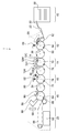
- FIG. 1 is a configuration diagram of an inkjet printing apparatus 1 according to an embodiment.
- the ink jet printing apparatus 1 includes a paper supply unit 10, a treatment liquid application unit 12, a drawing unit 14, a drying unit 16, a fixing unit 18, and a paper discharge unit 20.
- the inkjet printing apparatus 1 is a color inkjet printing apparatus that prints a color image on a sheet of paper 22 using aqueous ink.
- a water-based ink refers to an ink in which a coloring material such as a pigment or a dye is dissolved or dispersed in water and a water-soluble solvent.
- the paper 22 used in this example is a printing paper mainly composed of cellulose.
- the paper 22 is a form of a medium used for image formation.
- the ink jet printing apparatus 1 is a form of an image forming apparatus.
- the paper feed unit 10 is a mechanism that supplies the paper 22 to the treatment liquid application unit 12.
- a sheet 22 that is a sheet is stacked on the sheet feeding unit 10.
- the paper feed unit 10 is provided with a paper feed tray 50, and the paper 22 is fed from the paper feed tray 50 to the processing liquid application unit 12 one by one.
- the treatment liquid application unit 12 is a mechanism for applying the treatment liquid to the recording surface of the paper 22.
- the treatment liquid contains a component that aggregates or thickens the color material (pigment or dye) in the ink.
- Specific methods for agglomerating or thickening the color material include a treatment liquid that reacts with the ink to precipitate or insolubilize the color material in the ink, and a semi-solid substance (gel) containing the color material in the ink.
- Means for causing a reaction between the ink and the treatment liquid include a method of reacting an anionic coloring material in the ink with a cationic compound in the treatment liquid, an ink having different pH (potential of hydrogen) and the treatment liquid.
- the dispersion of the pigment in the ink is caused by changing the pH of the ink by mixing the pigment, and the pigment is aggregated.
- the dispersion of the pigment in the ink is caused by the reaction with the polyvalent metal salt in the treatment liquid.
- There is a method of aggregating. Examples of the treatment liquid application method include application by a roller, uniform application by spraying, and droplet ejection by an inkjet head.
- the sheet 22 fed from the sheet feeding unit 10 is received by the first transfer drum 52 and transferred to the processing liquid drum 54.
- the treatment liquid drum 54 is provided with a claw-shaped gripper 55 on the outer peripheral surface thereof, so that the front end of the paper 22 can be held by the gripper 55.
- the sheet 22 is rotated and conveyed by the rotation of the processing liquid drum 54 with the leading end held by the gripper 55.
- the suction hole is provided in the outer peripheral surface of the processing liquid drum 54, and the sheet 22 can be sucked and held on the peripheral surface of the processing liquid drum 54 by performing suction from the suction hole.
- the configuration of the treatment liquid application device 56 is not particularly limited.
- the treatment liquid application device 56 is disposed on the treatment liquid container in which the treatment liquid is stored, the measuring roller partially immersed in the treatment liquid in the treatment liquid container, and the measurement roller.
- the squeegee is in contact with the metering roller and a rubber roller that is pressed against the paper 22 on the processing liquid drum 54 and transfers the measured processing liquid to the paper 22.
- a certain amount of treatment liquid can be applied to the paper 22.
- the paper 22 on which the treatment liquid is applied by the treatment liquid application device 56 is conveyed to the position of the hot air ejection nozzle 58.
- the warm air ejection nozzle 58 can be configured to blow warm air toward the paper 22 with a constant air volume. It can be set as the structure which replaces with the warm air ejection nozzle 58, or performs drying using an infrared heater in combination with this.
- the sheet 22 to which the processing liquid is applied is transferred from the processing liquid drum 54 to the second transfer cylinder 30. Thereafter, the paper 22 is transferred from the second transfer cylinder 30 to the drawing drum 70 of the drawing unit 14.
- the drawing unit 14 is a mechanism that draws an image corresponding to an input image by ejecting ink and a transparent liquid by an inkjet method.
- the drawing unit 14 includes a drawing drum 70, recording heads 72C, 72M, 72Y, and 72K as drawing means, a transparent liquid discharge head 72CL, and a paper floating sensor 74.
- the drawing drum 70 holds the paper 22 on its outer peripheral surface and is driven to rotate.
- the drawing drum 70 includes a claw-shaped gripper 76 on its outer peripheral surface, and the gripper 76 can hold the leading edge of the paper 22.
- the sheet 22 is rotated and conveyed by the rotation of the drawing drum 70 with the leading end held by the gripper 76.
- the drawing drum 70 has a plurality of suction holes (not shown) on the peripheral surface, sucks the paper 22 from the suction holes, and sucks and holds the paper 22 on the peripheral surface.
- the paper floating sensor 74 detects the floating of the paper 22 held on the drawing drum 70. That is, the paper floating sensor 74 detects a certain amount or more of the paper 22 floating from the outer peripheral surface of the drawing drum 70.
- the sheet floating sensor 74 has a configuration in which, for example, a laser projector and a light receiver are separately arranged on both sides in the axial direction of the drawing drum 70 with the drawing drum 70 interposed therebetween.
- the laser light projected from the laser projector is blocked by the paper 22 and is not received by the light receiver.
- the paper floating sensor 74 detects the floating of the paper 22 from the amount of light received by the light receiver.
- the paper floating sensor 74 is arranged on the upstream side of the recording heads 72C, 72M, 72Y, 72K and the transparent liquid discharge head 72CL with respect to the paper conveyance direction which is the rotation direction of the drawing drum 70.
- the recording heads 72C, 72M, 72Y, and 72K correspond to inks of four colors of cyan (C), magenta (M), yellow (Y), and black (K), respectively, and ink droplets of the corresponding colors. Ink jet head that discharges water. Each of the recording heads 72C, 72M, 72Y, and 72K corresponds to one form of the ink ejection unit.
- the transparent liquid discharge head 72CL is an ink jet head that discharges droplets of transparent liquid.
- the transparent liquid discharge head 72CL corresponds to one form of the transparent liquid discharge unit.
- the transparent liquid may be called “clear ink”.
- the clear liquid is denoted as “CL”.
- ink containing color materials of C, M, Y, and K may be referred to as “color ink”.
- Each of the recording heads 72C, 72M, 72Y, and 72K is supplied with ink from an ink tank (not shown) that is an ink supply source of a corresponding color via a pipe path (not shown).
- the transparent liquid is supplied to the transparent liquid discharge head 72CL from a transparent liquid tank (not shown) that is a supply source of the transparent liquid via a pipe path (not shown).
- the recording heads 72C, 72M, 72Y, 72K and the transparent liquid discharge head 72CL are disposed close to the position facing the outer peripheral surface of the drawing drum 70.
- the recording heads 72 ⁇ / b> C, 72 ⁇ / b> M, 72 ⁇ / b> Y, 72 ⁇ / b> K and the transparent liquid discharge head 72 ⁇ / b> CL are sequentially arranged from the upstream side in the rotation direction of the drawing drum 70.
- Each of the recording heads 72C, 72M, 72Y, 72K and the transparent liquid discharge head 72CL is a full-line type inkjet head having a length corresponding to the maximum width of the image forming area on the paper 22, and the discharge surface of each head is A nozzle row in which a plurality of nozzles for discharging droplets are arranged over the entire width of the image forming area is formed.
- the recording heads 72C, 72M, 72Y, 72K and the transparent liquid discharge head 72CL are fixedly installed so as to extend in the conveyance direction of the paper 22, that is, the direction orthogonal to the rotation direction of the drawing drum 70.
- CMYK standard colors four colors
- the combination of ink colors and the number of colors is not limited to this embodiment, and light ink, dark ink, special color ink, and the like are used as necessary. May be added.
- a print head that discharges light ink (light ink) such as light cyan and light magenta
- a print head that discharges special color inks such as green and orange.
- the arrangement order of the recording heads for each color is not particularly limited.
- the transparent liquid discharge head 72CL is disposed on the most downstream side in the rotation direction of the drawing drum 70, and each color After the color ink is ejected, the transparent liquid is ejected.
- the transparent liquid discharge head 72CL may be disposed upstream of the color ink recording heads 72C, 72M, 72Y, 72K, or between any one of the color ink recording heads 72C, 72M, 72Y, 72K. You may arrange in.
- Ink droplets are ejected from the recording heads 72C, 72M, 72Y, and 72K toward the recording surface of the paper 22 held on the outer peripheral surface of the drawing drum 70.
- the ink comes into contact with the processing liquid on the processing liquid application unit 12, and the color material (pigment) dispersed in the ink is aggregated to form a color material aggregate.
- the color material flow on the paper 22 is prevented, and an image is formed on the recording surface of the paper 22.
- transparent liquid droplets are discharged from the transparent liquid discharge head 72CL toward the recording surface of the paper 22 held on the outer peripheral surface of the drawing drum 70.
- the droplet ejection timings of the recording heads 72C, 72M, 72Y, and 72K and the transparent liquid ejection head 72CL are synchronized with an encoder (not shown in FIG. 1) that detects the rotational speed disposed on the drawing drum 70.
- the recording heads 72C, 72M, 72Y, 72K and the transparent liquid discharge head 72CL are mounted on a carriage (not shown) to constitute one head unit.
- the carriage is movably provided between the drawing unit 14 and a maintenance unit (not shown).
- the maintenance unit is a processing unit that performs cleaning of each of the recording heads 72C, 72M, 72Y, 72K and the transparent liquid discharge head 72CL, capping for moisture retention, and the like.
- the maintenance unit is installed side by side with the drawing drum 70 in the axial direction of the rotation axis of the drawing drum 70.
- the paper 22 to which the color ink and the transparent liquid are applied in the drawing unit 14 is transferred from the drawing drum 70 to the third transfer cylinder 32.
- the paper 22 transferred to the third transfer cylinder 32 is transferred from the third transfer cylinder 32 to the drying drum 78 of the drying unit 16.
- the drying unit 16 dries the liquid component remaining on the paper 22 after image recording.
- the liquid component remaining on the paper 22 includes an ink solvent and a transparent liquid separated by the color material aggregation action.
- the drying unit 16 includes a drying drum 78, a first hot air jet nozzle 80 that is a first drying means, and a second hot air jet nozzle 82 that is a second drying means.
- the drying drum 78 is a drum that holds and conveys the paper 22 on the outer peripheral surface thereof.
- the drying drum 78 is provided with a claw-shaped gripper 79 on the outer peripheral surface thereof, and the leading end of the paper 22 can be held by the gripper 79.
- the sheet 22 is rotated and conveyed by the rotation of the drying drum 78 with the leading end held by the gripper 79.
- the first warm air ejection nozzle 80 and the second warm air ejection nozzle 82 are arranged at positions facing the outer peripheral surface of the drying drum 78, respectively.
- a drying process is performed by blowing warm air from the first warm air ejection nozzle 80 and the second warm air ejection nozzle 82 onto the recording surface of the paper 22 held and transported by the drying drum 78.
- the inkjet printing apparatus 1 includes a temperature / humidity sensor 68 as temperature / humidity measuring means, and the temperature / humidity sensor 68 measures the temperature and humidity of the air around the apparatus. Based on the measurement information of the temperature / humidity sensor 68, the conditions of the drying process in the drying unit 16 are controlled.
- the paper 22 that has been dried by the drying unit 16 is transferred from the drying drum 78 to the fourth transfer cylinder 34.
- the paper 22 transferred to the fourth transfer cylinder 34 is transferred from the fourth transfer cylinder 34 to the fixing drum 84 of the fixing unit 18.
- the fixing unit 18 includes a fixing drum 84, a first fixing roller 86, a second fixing roller 88, and an inline sensor unit 90.
- the first fixing roller 86, the second fixing roller 88, and the inline sensor unit 90 are disposed at positions facing the peripheral surface of the fixing drum 84, and the first fixing roller 86, the first inline sensor unit 90 are arranged from the upstream side in the rotation direction of the fixing drum 84. 2
- the fixing roller 88 and the inline sensor unit 90 are arranged in this order.
- the fixing drum 84 is a drum that holds and conveys the paper 22 on its outer peripheral surface.
- the fixing drum 84 is provided with a claw-shaped gripper 85 on the outer peripheral surface thereof, and the leading end of the paper 22 can be held by the gripper 85.
- the sheet 22 is rotated and conveyed by the rotation of the fixing drum 84 with the leading end held by the gripper 85.
- Fixing processing by the first fixing roller 86 and the second fixing roller 88 and an inspection by the inline sensor unit 90 are performed on the recording surface of the paper 22 held and transported by the fixing drum 84.
- Each of the first fixing roller 86 and the second fixing roller 88 has a roller width equivalent to that of the fixing drum 84 and is heated to a set temperature by a built-in heater (not shown).
- the first fixing roller 86 and the second fixing roller 88 heat and press the ink applied to the recording surface of the paper 22 to weld the self-dispersing polymer fine particles, which are thermoplastic resins in the ink, and form the ink into a film.
- the in-line sensor unit 90 includes a charge-coupled device (CCD) line sensor serving as an image reading unit that reads an image recorded on the sheet 22, and a laser displacement meter serving as a sheet deformation measuring unit that measures sheet deformation of a printed matter. Detection unit.
- CCD charge-coupled device
- the in-line sensor unit 90 captures an image recorded on the paper 22 conveyed by the fixing drum 84 with a CCD line sensor, and reads a printed image. Information such as image density and ejection defects of the recording heads 72C, 72M, 72Y, and 72K is obtained from the data of the read image read by the CCD line sensor.
- a plurality of laser displacement meters of the inline sensor unit 90 are installed at different positions in the width direction of the paper 22, and each of the laser displacement meters is conveyed by the fixing drum 84 after the drying process by the drying unit 16. The deformation amount of the paper 22 is measured.
- the sheet 22 on which the fixing process has been performed by the fixing unit 18 is transferred from the fixing drum 84 to the chain transport unit 96 and is sent to the paper discharge unit 20 by the chain transport unit 96.
- the paper discharge unit 20 collects the paper 22 on which the image is formed.
- the paper discharge unit 20 includes a paper discharge tray 92 that stacks and collects the paper 22.
- a gripper (not shown) of the chain transport unit 96 releases the grip of the paper 22 on the paper discharge tray 92 and stacks the paper 22 on the paper discharge tray 92.
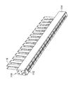
- FIG. 2 is a perspective view of the inkjet head bar 110.
- FIG. 2 shows a state in which the ejection surface is looked up from an obliquely downward direction of the inkjet head bar 110.
- the ink-jet head bar 110 is a full-line type line head in which a plurality of head modules 112 are arranged in the paper width direction and are elongated.
- a full line type line head is also called a page wide head.
- FIG. 2 shows an example in which 17 head modules 112 are connected, but the structure of the head modules 112, the number of head modules 112 and the arrangement form are not limited to the illustrated examples.
- Reference numeral 114 in the drawing denotes a base frame that serves as a frame for connecting and fixing a plurality of head modules 112 in a bar shape.
- Reference numeral 116 denotes a flexible substrate connected to each head module 112. The plurality of head modules 112 are attached to and integrated with the base frame 114 to constitute one inkjet head bar 110.
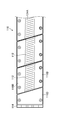
- FIG. 3 is a partially enlarged view of the inkjet head bar 110 viewed from the nozzle surface side.
- the head module 112 is supported by the module support member 118B from both sides in the up-down direction of FIG. 3, which is the short direction of the inkjet head bar 110, and is attached to the base frame 114 via the module support member 118B. Further, both end portions of the inkjet head bar 110 in the longitudinal direction are supported by a head protection member 118D.
- the slanted solid line shown with reference numeral 124A represents a nozzle row in which a plurality of nozzles are arranged in a row.
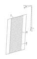
- FIG. 4 is a plan view of the nozzle surface 112A of the head module 112 as viewed from the discharge side.
- FIG. 4 is drawn with the number of nozzles reduced for convenience of illustration, for example, 32 ⁇ 64 nozzles 120 are two-dimensionally arranged on the nozzle surface 112A of one head module 112.
- “Nozzle surface” refers to the ejection surface on which the nozzle 120 is formed, and is synonymous with “nozzle formation surface”.
- the nozzle arrangement of the plurality of nozzles 120 arranged two-dimensionally is referred to as a “two-dimensional nozzle arrangement”.
- a direction parallel to the Y direction is referred to as a “sub-scanning direction”, and a direction parallel to the X direction is referred to as a “main scanning direction”.
- the head module 112 has an end surface on the long side along the V direction having an inclination of angle ⁇ with respect to the X direction, and an end surface on the short side along the W direction having an inclination of angle ⁇ with respect to the Y direction. And has a parallelogram shape in plan view.
- the specified recording resolution may be a recording resolution predetermined by the inkjet printing apparatus 1, or a recording resolution set by user selection or by automatic selection by a program corresponding to the printing mode. Also good.
- the recording resolution can be set to 1200 dpi, for example. dpi (dot per inch) is a unit notation representing the number of dots per inch.
- the projected nozzle array in which the nozzles in the two-dimensional nozzle array are projected (orthographically projected) along the main scanning direction achieves the maximum recording resolution in the main scanning direction.
- the nozzle density is equivalent to a single nozzle row in which each nozzle is arranged at approximately equal intervals.
- the “substantially equidistant” means that the droplet ejection points that can be recorded by the ink jet printing apparatus are substantially equidistant.
- the concept of “equally spaced” also includes cases where the intervals are slightly different in consideration of manufacturing errors and movement of droplets on the paper due to landing interference.
- the projection nozzle row also referred to as “substantial nozzle row”
- the nozzle numbers representing the nozzle positions can be associated with the arrangement order of the projection nozzles arranged along the main scanning direction.
- the arrangement form of the nozzles 120 in the head module 112 is not limited to the illustrated example, and various nozzle arrangement forms can be adopted.
- a linear arrangement of lines, a V-shaped nozzle arrangement, a polygonal nozzle arrangement such as a W-shape having a V-shaped arrangement as a repeating unit, etc. is also possible.
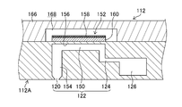
- FIG. 5 is a longitudinal sectional view showing a three-dimensional structure of one ejector 122 in the head module 112.
- the ejector 122 includes a nozzle 120, a pressure chamber 150 that communicates with the nozzle 120, and a piezoelectric element 152.
- the nozzle 120 communicates with the pressure chamber 150 via the nozzle channel 154.
- the pressure chamber 150 communicates with the supply side common branch passage 126 via the individual supply passage 124.
- the diaphragm 156 constituting the top surface of the pressure chamber 150 has a conductive layer (not shown) that functions as a common electrode corresponding to the lower electrode of the piezoelectric element 152.
- the walls of the pressure chamber 150 and other flow passages, the diaphragm 156, and the like can be made of silicon.
- the material of the diaphragm 156 is not limited to silicon, and an embodiment in which the diaphragm 156 is formed of a nonconductive material such as a resin is also possible.
- a conductive layer made of a conductive material is formed on the surface of the diaphragm member. Note that the diaphragm 156 itself may be made of a metal material such as stainless steel and serve as a diaphragm that also serves as a common electrode.
- a piezoelectric unimorph actuator is configured by the structure in which the piezoelectric element 152 is laminated on the vibration plate 156.
- the piezoelectric body 160 is deformed by applying a driving voltage to the individual electrode 158 that is the upper electrode of the piezoelectric element 152, and the volume of the pressure chamber 150 is changed by bending the diaphragm 156.
- a droplet is ejected from the nozzle 120 by the pressure change accompanying this volume change.
- the pressure chamber 150 is filled with new liquid (color ink or transparent liquid) from the supply-side common branch channel 126 through the individual supply channel 124.
- the operation of filling the pressure chamber 150 with liquid is referred to as “refill”.
- the configuration in which the diaphragm 156 is bent using the distortion deformation of the d 31 mode of the piezoelectric body 160 is illustrated, but the discharge is performed using the form using the d 33 mode or the shear mode (shear deformation). It is also possible to perform this.
- the plan view shape of the pressure chamber 150 is not particularly limited, and may be various forms such as a square, other polygons, a circle, or an ellipse.
- Reference numeral 166 in FIG. 5 denotes a cover plate.
- the cover plate 166 is a member that secures the movable space 168 of the piezoelectric element 152 and seals the periphery of the piezoelectric element 152.
- a supply-side liquid chamber and a recovery-side liquid chamber are formed above the cover plate 166.
- the supply side liquid chamber is connected to a supply side flow path (not shown) serving as a liquid supply source via a communication path (not shown).
- the collection-side liquid chamber is connected to a collection-side flow path (not shown) serving as a liquid collection destination via a communication path (not shown).
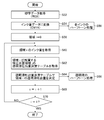
- FIG. 6 is a flowchart showing the flow of the correction process of the transparent liquid discharge amount.
- the flowchart of FIG. 2 is executed in accordance with a command from a system controller that controls the operation of the inkjet printing apparatus 1.
- the correction process of the transparent liquid discharge amount includes a test pattern printing process (step S10), a paper deformation degree reading process (step S12), a correction necessity determination process (step S14), and a correction coefficient calculation process (step S16). And a correction value introducing step (step S18).
- step S10 test pattern printing process
- step S12 paper deformation degree reading process
- step S14 a correction necessity determination process
- step S16 correction coefficient calculation process
- step S18 correction value introducing step
- the test pattern printing step (step S10) is a step of printing a test pattern by the inkjet printing apparatus 1.
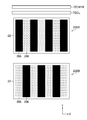
- FIG. 7 is a diagram showing an example of a test pattern to be printed.
- description will be made assuming that the paper transport direction is the Y direction and the paper width direction orthogonal to the paper transport direction is the X direction.
- the recording heads 72CMYK are described in order to comprehensively describe the recording heads of the respective colors of CMYK and to express them simply.
- Reference numeral 72CL in FIG. 7 denotes a transparent liquid discharge head.
- Each of the recording head 72CMYK and the transparent liquid discharge head 72CL has a nozzle row in which a plurality of nozzles are arranged at different positions in the X direction.
- a direction in which a plurality of nozzles are arranged in each of the recording head 72CMYK and the transparent liquid discharge head 72CL is referred to as a “nozzle row direction”.
- the X direction is the nozzle row direction.
- the Y direction in FIG. 7 is a direction perpendicular to the nozzle row direction and is referred to as “nozzle row vertical direction”.
- the nozzle row direction corresponds to the “first direction”
- the nozzle row vertical direction corresponds to the “second direction”.
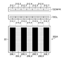
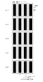
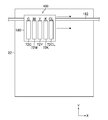
- the test pattern 202A illustrated in FIG. 7 is a pattern in which stripes extending in the vertical direction of the nozzle row are printed with color ink, and a transparent liquid is ejected between a plurality of stripes that are printed portions of the color ink. ing.
- An area to which color ink is applied is referred to as an ink application area 206.
- black is printed with four colors of CMYK inks superimposed.
- the area to which the transparent liquid is applied is called a transparent liquid application area 208.
- the transparent liquid application region 208 may be expressed as “transparent liquid stripe”.
- the droplet ejection of the transparent liquid may be expressed as “printing” with the transparent liquid.
- each of the ink and the transparent liquid is applied to different regions of the same paper 22 (that is, the single paper 22), and the ink application region 206 and the transparent liquid application region 208 are provided.
- the pattern is arranged alternately in the X direction. In the case of such a stripe pattern, it is necessary to print a test pattern 202B in which the ink application area 206 and the transparent liquid application area 208 are exchanged as shown in the lower part of FIG.
- the pattern in which the ink application region and the transparent liquid application region are arranged adjacent to each other is most easily understood, that is, the signal-to-noise ratio (when the amount of paper deformation is measured ( S / N ratio (signal-to-noise ratio) is high, and results are easy to stabilize.
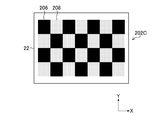
- the form of the test pattern is not limited to the example of FIG. 7, and various forms can be adopted.
- a test pattern 202C shown in FIG. 8A is a checkered flag type pattern.
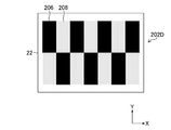
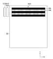
- the test pattern 202D shown in FIG. 8B is obtained by shortening the length in the Y direction from the striped test pattern 202A shown in the upper part of FIG. 7 and the striped test pattern 202B shown in the lower part of FIG. These striped patterns are joined up and down (about half the length) and printed on the same sheet as a single pattern as a whole.
- ink application region 206 and the transparent liquid application region 208 of the test pattern 202C shown in FIG. 8A and the test pattern 202D illustrated in FIG. 8B are also “striped”.
- the ink application area 206 and the transparent liquid application area 208 are arranged adjacent to each other in the nozzle row direction.
- the ink application area 206 and the transparent liquid application area 208 are adjacent to each other with a boundary therebetween, but a slight gap between the ink application area 206 and the transparent liquid application area 208 is acceptable. Is done. That is, it is understood that “both sides are arranged side by side” when both areas are arranged with a slight gap between the ink application area 206 and the transparent liquid application area 208.
- test pattern 202C shown in FIG. 8A since the transparent liquid is discharged over the entire range of the nozzle row of the transparent liquid discharge head 72CL in the test pattern 202C, the test pattern shown in FIG. 8A is used. It is not necessary to print a test pattern in which the 202C ink application area 206 and the transparent liquid application area 208 are interchanged. This is the same for the test pattern 202D shown in FIG. 8B, and it is not necessary to print a test pattern in which the ink application area 206 and the transparent liquid application area 208 of the test pattern 202D shown in FIG.
- each stripe of the transparent liquid application area for ejecting the transparent liquid has a width that is an integral multiple of the X direction width of the head module in the transparent liquid discharge head. Is preferred. That is, when N represents an integer of 1 or more, it is preferable that the width of the transparent liquid application region in the X direction matches the width of N head modules.
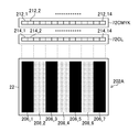
- FIG. 9 is an explanatory diagram illustrating the relationship between the stripe width and the head module 214_r in the test pattern 202A.
- the subscript r is an index indicating the head module number, where r is an integer from 1 to 7.
- the color ink recording head 72CMYK is configured by combining seven head modules 212_r.
- the ink application region 206_1 in the test pattern 202A shown in FIG. 9 is printed by the head module 212_1 of the recording head.
- each of the ink application areas 206_3, 206_5, and 206_7 is printed by the head modules 212_3, 212_5, and 212_7 at the corresponding positions.
- the transparent liquid application area 208_2 in the test pattern 202A is printed by the head module 214_2 of the transparent liquid discharge head 72CL.
- each of the transparent liquid application areas 208_2, 208_4, 208_6 is printed by the head modules 214_2, 214_4, 214_6 at the corresponding positions.
- test pattern 202B in which the ink application areas 206_3, 206_5, and 206_7 and the transparent liquid application areas 208_2, 208_4, and 208_6 are interchanged is omitted, but the test pattern 202B is similarly provided in units of head modules. Stripes are printed.
- FIG. 10 is an explanatory diagram showing another example of the relationship between the stripe width and the head module 214_n in the test pattern 202A.
- the ink application area 206_1 in the test pattern 202A is printed by the head modules 212_1 and 212_2 of the recording head 72CMYK. Similarly, each of the ink application areas 206_3, 206_5, and 206_7 is printed by two head modules at the corresponding positions.
- the transparent liquid application area 208_2 in the test pattern 202A is printed by the head modules 214_3 and 214_4 of the transparent liquid discharge head 72CL. Similarly, each of the transparent liquid application areas 208_4 and 208_6 is printed by two head modules at corresponding positions.
- test pattern 202B in which the ink application area 206 and the transparent liquid application area 208 described in FIG. 7 are replaced is omitted, but the test pattern 202B is also similar to a plurality of adjacent head modules. Each stripe is printed in units.
- the paper deformation degree reading step (step S12) shown in FIG. 6 is a step of reading the degree of paper deformation from the printed material of the test pattern obtained in step S10.
- the degree of paper deformation is synonymous with the degree of paper deformation.
- a numerical value obtained by quantifying the degree of paper deformation is the paper deformation amount. “Reading” includes obtaining information.
- the degree of paper deformation is read automatically or manually.
- the case of automatically reading the degree of paper deformation from the printed test pattern is a form in which, for example, the degree of paper deformation in the printed test pattern is actually measured, and information indicating the degree of paper deformation is obtained from the measurement result. .
- the case where the degree of sheet deformation is read “manually” from the printed material of the test pattern corresponds to, for example, a form in which the operator grasps the degree of sheet deformation visually and / or tactilely.
- the degree of paper deformation read by the operator by visual or tactile sensation can be evaluated or classified according to a predetermined standard, and information indicating the evaluation result or classification result is treated as information indicating the degree of paper deformation. .
- the sheet deformation degree reading step (step S12) corresponds to one form of the information acquisition step.
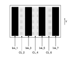
- FIG. 11 is an explanatory diagram when the degree of sheet deformation in the test pattern 202A is automatically read.
- Ink_1, Ink_3, Ink_5, and Ink_7 shown in FIG. 11 represent positions in different ink application regions.
- CL_2, CL_4, and CL_6 represent positions in different transparent liquid application regions 208 on the paper 22, respectively.
- a measuring means such as a laser displacement meter.
- the stripes in the ink application area 206 are preferably measured at two places on the left and right in the same stripe except for the end in the X direction. In the following description, “L” is shown on the left and “R” is shown on the right. Of course, instead of the measurement in two places on the left and right sides in the X direction in one stripe, the stripe in the ink application area itself may be divided into two.
- FIG. 12 is an example of the shape profile of the irregularities on the paper surface.
- the horizontal axis in FIG. 12 represents the position in the Y direction, and the vertical axis represents the height in the direction (Z direction) perpendicular to the paper surface of the paper surface.
- the sheet deformation amount representing the degree of sheet deformation is obtained from this shape profile.
- Various indexes can be used as indexes that quantitatively represent the sheet deformation amount. Examples of indices that can be used as the sheet deformation amount are shown below.
- the total length of the shape profile of the irregularities on the paper surface can be used as the paper deformation amount.
- the total length of the curve representing the shape profile shown in FIG. 12 reflects the degree of sheet deformation. When the degree of paper deformation is small, the total length of the curve is shortened, and when the degree of paper deformation is large, the total length of the curve is long.
- the shape profile of the unevenness on the sheet surface includes a component such as the inclination of the measurement table, a correction process for removing the inclination component is performed.
- the characteristic value of the shape profile of the irregularities on the paper surface can be used as the paper deformation amount.
- As the characteristic value of the shape profile for example, arithmetic average roughness Ra, maximum height, or M-point average height (where M represents an integer of about 10), or an appropriate combination thereof Can be used.
- a print sample refers to a printed matter that has been printed.
- the shape profile as illustrated in FIG. 8A and FIG. 8B is Fourier transformed, decomposed into intensities for each frequency, and after applying a filter (low-pass filter) taking human visibility into account, the intensity is obtained, The obtained strength can be used as the sheet deformation amount.
- the print sample refers to a printed matter that has been printed.
- Example 4 Of course, (Example 1) to (Example 3) exemplified above may be combined as appropriate. Needless to say, increasing the number of measurements is effective in increasing the accuracy of the data.
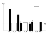
- FIG. 13 is a diagram showing an example of the sheet deformation amount at each position shown in FIG.
- the horizontal axis in FIG. 13 represents the position in the X direction on the paper, and the vertical axis represents the amount of paper deformation.
- a sheet deformation amount at a position x on the sheet is expressed as P (x).
- the sheet deformation amount at the position of Ink_1 is expressed as P (Ink_1).
- P0 shown in FIG. 13 is a threshold value of the sheet deformation amount used as a specified value as a determination criterion for determining necessity of correction in the correction necessity determination step (step S14 in FIG. 2).
- P0 in this example is determined as a value representing the upper limit of the allowable sheet deformation amount.
- the amount of deformation of a sheet can be measured for a sheet on which nothing is printed, and the average of the values can be defined as P0.
- the operator When manually reading the degree of paper deformation, the operator reads the degree of paper deformation at each position visually or tactilely, and ranks the degree of paper deformation read according to a predetermined standard. By dividing, data representing contents similar to those in FIG. 13 is obtained.
- step S14 in FIG. 6 the sheet deformation amount representing the degree of sheet deformation obtained in step S12 is compared with a predetermined value to determine whether the transparent liquid discharge amount needs to be corrected. This is a step of discriminating The specified value can be P0 described in FIG. If the sheet deformation amount is equal to or less than the specified value, it is determined that correction is not necessary, a YES determination is made in step S14, and the processing in FIG.
- step S14 If it is determined in step S14 that the sheet deformation amount exceeds the specified value, it is determined that correction of the transparent liquid discharge amount is necessary, and the process proceeds to a correction coefficient calculation step (step S16).
- the correction coefficient calculation step (step S16 in FIG. 6) is a step of obtaining a correction coefficient for adjusting the transparent liquid discharge amount in each transparent liquid application region to an appropriate amount from the sheet deformation amount data obtained in step S14. is there.
- CL_j is a region of interest
- Ink_j-1R and Ink_j + 1L are ink application regions on both sides of CL_1.
- the value of P (Ink_j-1R) ⁇ P0 or the value of P (Ink_j + 1L) ⁇ P0 being large means that the ink application area is extended, that is, the discharge of the transparent liquid It means that there is a shortage. Therefore, if the value of P (Ink_j-1R) ⁇ P0 is ⁇ P (Ink_j ⁇ 1R) and the value of P (Ink_j + 1L) ⁇ P0 is ⁇ P (Ink_j + 1L), ⁇ P (Ink_j-1R) and ⁇ P ( Correction is performed such that the larger the value of (Ink_j + 1L), the greater the CL_j discharge amount.
- the value of [1] is not a problem for CL_2. That is, the value of the paper deformation amount P (CL_2) at the position CL_2 is within the normal range. However, the value of [2] is large. That is, the values of ⁇ P (Ink_1R) and ⁇ P (Ink_3L) are large and the discharge amount of the transparent liquid is insufficient.
- a value obtained by multiplying the current transparent liquid discharge amount by ⁇ 1 and ⁇ 2 obtained above is set as a new transparent liquid discharge amount. That is, the corrected transparent liquid discharge amount is obtained by multiplying the transparent liquid discharge amount before correction, which is the current discharge amount of the transparent liquid, by ⁇ 1 and ⁇ 2 obtained above. The corrected value of the transparent liquid discharge amount is applied as the correction value.
- k types of printing with different discharge amounts of the transparent liquid are carried out, a place where the amount of paper deformation in the ink application area and the transparent liquid application area is the smallest is obtained, and the value is applied as a correction value.
- k is an integer of 2 or more.
- the k types of printing with different discharge amounts of the transparent liquid indicate outputting k types of test patterns with the discharge amount level of the transparent liquid being Lv_1, Lv_2,..., Lv_k.
- FIG. 14 shows an example in which five types of test patterns with different levels of the transparent liquid discharge are printed.
- the discharge amount level of the transparent liquid increases in the order of Lv_1, Lv_2,..., Lv_5.
- the amount of paper deformation at each position is measured in the same manner as the example described in FIG.
- FIG. 15 is a graph showing the amount of paper deformation for each transparent liquid discharge amount level at position j.
- a graph line indicated by a thick solid line in FIG. 15 indicates P (CL_j), and a graph line indicated by a thick broken line indicates an average value of P (Ink_j-1R) and P (Ink_j + 1L).
- the value of the optimum point may be obtained by interpolation calculation, and the value may be used as a correction value. Further, the operator may determine the optimum point from the test pattern and use the value as a correction value.
- the average value of the sheet deformation amount in the left and right ink application regions of CL_j is used.
- the average value as in this example is not necessarily used, and the sheet deformation amount in the left and right ink application regions is not changed. It may be used to determine the optimum discharge amount level.
- the above-described modification increases the number of test patterns to be printed first, but the data convergence There is an advantage that it is quick.
- the correction value introducing step (step S18) shown in FIG. 6 is a step of correcting the discharge amount of the transparent liquid by introducing the correction value obtained in step S16. That is, the correction value is applied to correct the discharge amount of the transparent liquid to determine an appropriate discharge amount.
- correction coefficient calculation step S16 corresponds to one form of the “information processing step”.
- the correction of the discharge amount of the transparent liquid in this example is specifically performed by correcting the transparent liquid discharge amount determination table.
- the transparent liquid discharge amount determination table is a table that defines the correspondence between the total amount of ink scheduled to be ejected onto a unit area and the amount of transparent liquid applied to the unit area.
- the unit area is an area having a minimum unit area for controlling the application amount of the transparent liquid, and refers to, for example, an area of about 10 mm square on the paper.
- the size of the unit area can be set to an appropriate size.
- the unit area is grasped as a pixel area on the image data.
- the transparent liquid discharge amount determination table may be in the form of a lookup table or in the form of an arithmetic expression using a function.
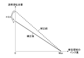
- FIG. 16 is an explanatory diagram showing an example of a transparent liquid discharge amount determination table.
- the horizontal axis of FIG. 16 represents the total amount of ink scheduled to be ejected onto the unit area. In FIG. 16, it is expressed as “ink amount of unit area”.
- the notation “Max” represents the maximum total amount of ink that can be output in the ink jet printing apparatus, and in the example of FIG. 1, it means the maximum value of the total amount of ink that combines four CMYK colors that can be applied to the unit area.
- shaft of FIG. 16 has shown the transparent liquid amount provided to a unit area
- a graph indicated by a broken line represents a transparent liquid discharge amount determination table before correction
- a graph indicated by a solid line represents a transparent liquid discharge amount determination table after correction.
- the transparent liquid discharge amount determination table is changed by changing the inclination of the entire graph.
- the corrected transparent liquid discharge amount determination table is obtained.
- FIG. 16 shows an example in which the correction coefficient is “0.8 times”.
- the ink amount of the unit area “0” corresponds to the absence of color ink, that is, the non-image area portion.
- FIG. 17 is an explanatory diagram showing an example of a transparent liquid discharge amount determination table when the method described in the above [Modification] is applied.
- the transparent liquid discharge amount determination table of the optimal discharge amount level is adopted by the method described in FIGS.
- the transparent liquid discharge amount determination table of Lv_4 from among those shown in FIG. 17 is adopted.
- 16 and 17 are determined for each position j of the transparent liquid application area 208 in the test pattern.
- a discharge amount determination table TB (j) is defined.
- the “plateau” is a section where the transparent liquid amount is constant regardless of the ink amount. Within the plateau range, a certain amount of transparent liquid is ejected regardless of the amount of ink.
- the transparent liquid amount may be “0” when the ink amount in the unit area is smaller than “Max”.
- the transparent liquid discharge amount determination table only needs to show a tendency that the transparent liquid amount decreases as the ink amount increases, and includes a portion where the transparent liquid amount is constant as the ink amount increases. It is acceptable.
- the flow chart of FIG. 6 can be implemented when performing the adjustment operation of the setup when the transparent liquid discharge head 72CL is mounted on the inkjet printing apparatus 1.
- FIG. 20 is a flowchart of the determination process of the transparent liquid discharge amount at the time of printing based on the print data.
- the flowchart of FIG. 20 is executed in accordance with a command from a system controller that controls the operation of the inkjet printing apparatus 1.
- print data including image data to be printed is acquired.
- the format of the print data is not particularly limited. For example, 8-bit 24-bit color image data for each of RGB colors of red (R), green (G), and blue (B) is acquired.
- the ink amount data conversion step (step S54) of this example includes a color conversion step of converting RGB image data into CMYK ink amount data as image data representing the ink amounts of the CMYK colors.
- the CMYK ink amount data generated in the ink amount data converting step (step S54) is sent to the halftone process (step S56) for each ink for each CMYK color, and converted to dot data for each color. .
- i is an index representing the position of each image area divided by the size of the unit area.
- FIG. 21 is a conceptual diagram in a case where an image, which is CMYK ink amount data, is divided into regions having a unit area size. Each cell shown by the grid in FIG. 21 has a unit area size of about 10 mm square, for example.
- the index i indicating the position of each area is an integer from 0 to “I ⁇ 1”.
- I represents the total number of divided areas, and is an integer of 2 or more.
- FIG. 21 shows an example in which the area is divided into I areas. However, instead of the division process, a calculation method of changing the area of interest by sequentially moving the window of the size of the unit area. It may be adopted.
- a “window” corresponds to a window function that defines an area having a specific number of pixels of interest as a target of arithmetic processing in an image.
- step S60 in FIG. 20 the process proceeds to step S60 in FIG. 20 to acquire the ink amount of the region i that is the region of interest.
- the ink amount of the region i can be grasped from the ink amount data of CMYK, and information on the total amount of CMYK ink for the region i is acquired.
- a transparent liquid discharge amount determination table for the correction section area j of the transparent liquid to which the area i belongs is acquired (step S62).
- j is an index representing the position of the correction partition area, and corresponds to the position j described with reference to FIG. That is, the corrected partition area j is an area corresponding to the position j of the transparent liquid application area 208.
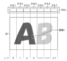
- FIG. 22 is an explanatory diagram of processing for determining the transparent liquid application amount of the region of interest in the image to be printed.
- the range of the nozzle example in the X direction in the transparent liquid discharge head 72CL is divided into seven regions according to the length of the X direction nozzle row of the head module 214_r.
- the area is divided into seven areas (correction division areas j) corresponding to the head modules 214_r.
- step S62 in FIG. 20 the process proceeds to step S64, and the transparent liquid discharge amount in the region i is determined with reference to the transparent liquid discharge amount determination table acquired in step S62.
- the information is sent to the transparent liquid halftone process (step S66) and converted into dot data for ejecting the transparent liquid. Based on the dot data of the transparent liquid, droplet ejection is performed by the transparent liquid discharge head 72CL.
- step S64 in FIG. 20 the process proceeds to step S68, and the index i representing the position of the region of interest is incremented to “i + 1”.
- the image of the print data to be printed is divided into areas of unit area size, and for each area i, from the total amount of ink to be ejected, using the transparent liquid discharge amount determination table, The transparent liquid discharge amount of each area is determined. Then, the droplets of the transparent liquid are ejected according to the determined transparent liquid discharge amount.
- Ink is ejected from the recording head 72CMYK in accordance with the dot data generated by the halftone process in step S56 described in FIG. 20, and the transparent liquid discharge head 72CL is in accordance with the dot data generated by the halftone process in step S66.
- Printing is performed by discharging the transparent liquid from the liquid crystal. This printing process corresponds to one form of the image forming process.
- FIG. 23 is a block diagram showing the configuration of the control system of the inkjet printing apparatus 1.
- elements corresponding to those of the configuration described in FIG. 1 are denoted by the same reference numerals, and description thereof is omitted.
- the control device 300 is realized by computer hardware and software. Software is synonymous with "program”.
- the control device 300 includes a system controller 302, a communication unit 304, a print data acquisition unit 306, a memory 308, a program storage unit 310, a test pattern generation unit 312, a display unit 314, and an operation unit 316. Prepare.
- the system controller 302 functions as a control unit that performs overall control of each unit of the inkjet printing apparatus 1 and also functions as a calculation unit that performs various calculation processes.
- the system controller 302 includes a central processing unit (CPU) and its peripheral circuits, and operates according to a control program.
- the program storage unit 310 stores a control program executed by the system controller 302 and various data necessary for control.
- the communication unit 304 includes a required communication interface.
- the control device 300 is connected to the host computer 502 via the communication unit 304 and can transmit and receive data to and from the host computer 502.
- the “connection” here includes a wired connection, a wireless connection, or a combination thereof.
- the communication unit 304 may be equipped with a buffer memory for speeding up communication.
- the print data acquisition unit 306 is an interface unit that acquires print data representing an image to be printed.
- the data format of the print data is not particularly limited. In this example, an RGB image of 8 bits (256 gradations) is used for each RGB color as print data. However, the image is not limited to an RGB image, and may be a CMYK image. Further, the number of gradations (number of bits) of the signal is not limited to this example.
- the print data acquisition unit 306 can be configured with a data input terminal that captures an image from an external or other signal processing unit in the apparatus.
- a wired or wireless communication interface unit may be employed, or a media interface unit that reads and writes a portable external storage medium such as a memory card may be employed. An appropriate combination of these may be used.
- the communication unit 304 can play the role of the print data acquisition unit 306.
- the memory 308 functions as a temporary storage unit for various data including the print data fetched from the print data acquisition unit 306.
- the test pattern generation unit 312 generates test pattern data as described in FIG. 7, FIG. 8A, and FIG. 8B.
- the test pattern generation unit 312 may be configured to store predetermined test pattern data, or may be configured to adaptively generate test pattern data.
- the display unit 314 and the operation unit 316 constitute a user interface.
- the operation unit 316 may employ various input devices such as a keyboard, a mouse, a touch panel, and a trackball, and may be an appropriate combination thereof.
- the form by which the display part 314 and the operation part 316 are comprised integrally is also possible like the structure which has arrange
- the operator uses the operation unit 316 while viewing the contents displayed on the screen of the display unit 314 to input various information such as input of printing conditions, selection of image quality mode, input / editing of attached information, and information search. be able to. Further, the operator can confirm the input content and other various information through the display on the display unit 314.
- the control device 300 includes an image correction processing unit 318, a color ink halftone processing unit 320, a transparent liquid halftone processing unit 322, and a table storage unit 324.
- the image correction processing unit 318 performs various conversion processes and correction processes for print data.
- Conversion processing for print data includes pixel number conversion, gradation conversion, color conversion, and the like.
- the correction processing includes density correction in accordance with the characteristics of the recording head 72CMYK, undischarge correction for suppressing the visibility of image defects by the undischarge nozzle, and the like.
- the color ink halftone processing unit 320 performs halftone processing for converting CMYK color image data corresponding to CMYK color ink amount data into binary or multivalued dot image data.
- a halftone processing method a known method such as a dither method or an error diffusion method can be used.
- data of n values (n is an integer of 2 or more and less than m) that can be recorded by a recording head by quantizing multi-tone image data of m values (m is an integer of 3 or more). It is processing to convert to.
- gradations for example, 256 gradations
- the halftone process for converting the image data into binary or multi-value dot image data is performed.
- the clear liquid halftone processing unit 322 and the color ink halftone processing unit 320 may adopt the same halftone algorithm or different halftone algorithms.
- the table storage unit 324 is a storage unit that stores a transparent liquid discharge amount determination table 326. As described with reference to FIGS. 20 and 21, the transparent liquid discharge amount determination table 326 is determined for each correction partition region j.
- the control device 300 includes a paper feed control unit 330, a processing liquid application control unit 332, a conveyance control unit 334, an image recording control unit 336, a transparent liquid discharge control unit 338, a drying control unit 340, and a fixing control unit. 342.
- the paper feed control unit 330 controls the paper feed operation of the paper feed unit 10 in accordance with a command from the system controller 302.
- the processing liquid application control unit 332 controls driving of each unit of the processing liquid application unit 12 (such as the processing liquid application device 56 described with reference to FIG. 1) in response to a command from the system controller 302.
- the transport control unit 334 controls driving of each unit of the paper transport unit 410 in accordance with a command from the system controller 302.
- the paper transport unit 410 includes the processing liquid drum 54, the drawing drum 70, the drying drum 78, the fixing drum 84, the chain transport unit 96, the first transfer drum 52, the second transfer drum 30, and the third drum described in FIG.
- a transfer drum 32 and a fourth transfer drum 34 are included.
- the paper transport unit 410 includes a drive unit such as a motor as a power source (not shown) and a motor drive circuit.
- the inkjet printing apparatus 1 includes an encoder 412 and various sensors 414.
- the encoder 412 is provided on the drawing drum 70 (see FIG. 1) of the paper transport unit 410.
- a discharge trigger signal (pixel trigger) is issued based on the detection signal of the encoder 412.
- the ejection timings of the recording head 72CMYK and the transparent liquid ejection head 72CL are synchronized with the detection signal of the encoder 412. Thereby, the landing position can be determined with high accuracy.
- the sensor 414 includes a paper detection sensor, a temperature sensor, a humidity sensor, a pressure sensor, and the like (not shown) in addition to the paper floating sensor 74 described in FIG.
- the system controller 302 performs necessary control based on information obtained from the sensor 414.
- the image recording control unit 336 controls the driving of the recording head 72CMYK according to a command from the system controller 302. Control for outputting a test pattern is performed by a combination of the test pattern generation unit 312, the system controller 302, and the image recording control unit 336. A combination of the test pattern generation unit 312, the system controller 302, and the image recording control unit 336 corresponds to one form of “test pattern printing control unit”.
- the transparent liquid discharge control unit 338 controls the driving of the transparent liquid discharge head 72CL in accordance with a command from the system controller 302.
- the drying control unit 340 controls the drying processing operation of the drying unit 16 according to a command from the system controller 302.
- the fixing controller 342 controls the driving of the first fixing roller 86 and the second fixing roller 88 of the fixing unit 18 in accordance with a command from the system controller 302.
- the inkjet printing apparatus 1 includes an image reading unit 422 and a paper deformation measurement unit 424.
- the image reading unit 422 and the sheet deformation measuring unit 424 of this example are included in the inline sensor unit 90 described with reference to FIG.
- the CCD line sensor mounted on the detection unit of the in-line sensor unit 90 corresponds to the image reading unit 422, and the laser displacement meter corresponds to the paper deformation measuring unit 424.
- the data of the read image acquired by the image reading unit 422 is sent to the image correction processing unit 318 and used for image correction calculation.
- the paper deformation measuring unit 424 measures the unevenness of the recording surface of the test printed material 430 on which the test chart described in the drawing is printed.
- the paper deformation measuring unit 424 corresponds to one form of “deformation measuring means”.
- the control device 300 includes a sheet deformation amount calculation unit 350, an information acquisition unit 360, a correction necessity determination unit 362, a specified value storage unit 364, a correction value calculation unit 366, and a transparent liquid discharge amount determination table change unit 368. With.
- the paper deformation amount calculation unit 350 performs an operation of calculating the paper deformation amount as information representing the degree of paper deformation based on the measurement data obtained from the paper deformation measurement unit 424.
- the sheet deformation amount calculation unit 350 calculates the value of the sheet deformation amount based on a predetermined specific index as exemplified in (Example 1) to (Example 4) based on the shape profile described in FIG. To do.
- the sheet deformation amount corresponds to one form of “medium deformation amount”. It should be noted that the function of the sheet deformation amount calculation unit 350 can be mounted in the unit of the sheet deformation measurement unit 424.
- the information acquisition unit 360 is an interface unit that acquires information on the amount of paper deformation.
- the information acquisition unit 360 corresponds to a form of “information acquisition unit”, and a process of acquiring information by the information acquisition unit 360 corresponds to a form of “information acquisition process”.
- the information acquisition unit 360 can take in the information on the sheet deformation amount generated by the sheet deformation amount calculation unit 350 in the control device 300.
- the sheet deformation amount calculation unit 350 plays a role of the information acquisition unit 360, and the sheet deformation amount calculation unit 350 and the information acquisition unit 360 can be considered as an integrated configuration. .
- the information acquisition unit 360 can take in information on the amount of paper deformation generated by a device external to the control device 300 (for example, another computer not shown). Furthermore, the information acquisition unit 360 can take in information on the amount of paper deformation manually read by the operator.
- the sheet deformation amount calculation unit 350 plays a role of the information acquisition unit 360.
- the information acquisition unit 360 may be integrated. Further, it can be understood that the sheet deformation measuring unit 424 and the sheet deformation amount calculating unit 350 together constitute an information acquisition unit.
- the correction necessity determination unit 362 determines whether the correction of the transparent liquid discharge amount is necessary based on the sheet deformation amount.
- the specified value storage unit 364 is a storage unit that stores a specified value that is used as a threshold value that serves as a reference for determination by the correction necessity determination unit 362.
- the correction value calculation unit 366 calculates the correction value of the transparent liquid discharge amount when the correction necessity determination unit 362 determines that the correction of the transparent liquid discharge amount is necessary.
- the correction value calculation unit 366 can perform the correction coefficient calculation process described in step S16 of FIG.
- the correction value calculation unit 366 corresponds to one form of “correction value calculation means”.
- the transparent liquid discharge amount determination table changing unit 368 performs a process of changing the transparent liquid discharge amount determination table 326 by applying the correction value obtained by the correction value calculation unit 366.
- the transparent liquid discharge amount determination table changing unit 368 may rewrite and update the uncorrected table stored in the table storage unit 324, or additionally store the newly created corrected table in the table storage unit 324. It may be configured.
- the transparent liquid discharge amount determination table changing unit 368 corresponds to one form of “transparent liquid discharge amount determination table changing means”.
- the portion of the functional block surrounded by the alternate long and short dash line can be regarded as the transparent liquid discharge amount determining device 370.
- the transparent liquid discharge amount determination device 370 illustrated in FIG. 23 includes an information acquisition unit 360, a correction necessity determination unit 362, a specified value storage unit 364, a correction value calculation unit 366, and a transparent liquid discharge amount determination table change unit 368. .
- the correction value calculation unit 366 and the transparent liquid discharge amount determination table change unit 368 correspond to a form of “information processing unit”.
- the transparent liquid discharge amount determination device 370 can include at least one of the sheet deformation amount calculation unit 350 and the table storage unit 324. Further, the transparent liquid discharge amount determination device 370 can be configured to include a paper deformation measurement unit 424 in addition to the paper deformation amount calculation unit 350.
- the transparent liquid discharge amount determination device 370 of the present example has a configuration included as a functional block in the control device 300, but the control device 300 can be realized by one or a plurality of computers. . Similarly, the function of the transparent liquid discharge amount determination device 370 can be realized by one or a plurality of computers.
- the process for correcting the discharge amount of the transparent liquid described in the above-described embodiment corresponds to one form of the transparent liquid discharge amount determination method.
- a method of recording an image on the paper 22 by the ink jet printing apparatus 1 and applying a transparent liquid to obtain a printed matter can be grasped as an image forming method.
- the inkjet printing apparatus 1 using a full-line type head has been described with reference to FIG. 1, the scope of application of the present invention is not limited to this, and while moving a short recording head such as a serial type (shuttle scan type) head, The present invention can also be applied to an ink jet printing apparatus that records an image by a plurality of head scans.
- a short recording head such as a serial type (shuttle scan type) head
- the present invention can also be applied to an ink jet printing apparatus that records an image by a plurality of head scans.
- FIG. 24 is a schematic plan view of a drawing unit in a serial scan type inkjet printing apparatus 600 according to another embodiment.
- elements similar to those described with reference to FIG. 24 are similar to those described with reference to FIG.
- Each of the CMYK color recording heads 72C, 72M, 72Y, 72K and the transparent liquid ejection head 72CL shown in FIG. 24 has a nozzle row in which nozzles (not shown) are arranged along the Y direction, which is the paper transport direction. .
- the nozzle row direction is the Y direction
- the nozzle row vertical direction is the X direction.
- Each of the recording heads 72C, 72M, 72Y, and 72K shown in FIG. 24 may be configured by a single head module, or may be configured by combining a plurality of head modules.
- the recording heads 72C, 72M, 72Y, 72K and the transparent liquid discharge head 72CL are mounted on the carriage 180.
- the carriage 180 is supported by the guide rail 182 and can reciprocate in the direction parallel to the X direction along the guide rail 182.
- the paper 22 is transported in the Y direction by a paper transport mechanism (not shown).
- the test chart for correcting the transparent liquid discharge amount has a form as shown in FIG. In FIG. 25, the recording heads 72C, 72M, 72Y, and 72K shown in FIG.
- FIG. 25 is a diagram showing an example of a test pattern printed by the inkjet printing apparatus 600 shown in FIG.
- the test pattern 602A illustrated in FIG. 25 is a pattern in which stripes extending in the X direction are printed with color ink, and a transparent liquid is ejected between a plurality of stripes which are color ink print portions. .
- FIG. 25 shows an example in which the nozzle row of the transparent liquid discharge head 72CL is divided into five regions in the Y direction, but the number of divisions of the nozzle row can be an arbitrary number of 2 or more.
- test pattern 602B is a test pattern in which the ink application area 206 and the transparent liquid application area 208 in the test pattern 602A are interchanged.
- Transparent liquid As components of the transparent liquid, it is preferable to use water and a high-boiling organic solvent having a higher SP (Solubility Parameter) value representing a solubility parameter than the high-boiling organic solvent in the ink. As a result, the paper can be stretched only by applying a smaller amount.
- SP Solubility Parameter
- the surface tension of the transparent liquid is preferably smaller than the surface tension of the ink, and the viscosity of the transparent liquid is preferably lower than the viscosity of the ink. This allows the paper to penetrate faster than ink, and as a result, the paper can be stretched in a smaller amount.
- the resolution of the transparent liquid discharge head may be lower than that of the recording head for discharging color ink.
- the transparent liquid discharge head is not limited to the ink jet type discharge head, and may be a discharge head such as a dispenser.
- Paper deformation measuring means For example, a combination of an illumination unit that irradiates illumination light at a shallow angle with respect to the recording surface of the paper 22 and a camera that captures the recording surface of the paper 22 can be used. By illuminating the illumination light at a shallow angle with respect to the recording surface of the paper 22, a shadow due to the unevenness of the paper surface is observed. The amount of paper deformation can be grasped by photographing the shadow with a camera and analyzing the obtained photographed image.
- the configuration in which the paper deformation measurement unit 424 is mounted on the detection unit of the inline sensor unit 90 has been described.
- a configuration in which a paper deformation measurement unit is installed in the paper discharge unit 20 or Further, a form in which the sheet deformation measuring means is installed further downstream of the paper discharge unit 20 is also possible.
- the conveyance means for conveying the paper 22 is not limited to the drum conveyance method illustrated in FIG. 1, and various forms such as a belt conveyance method, a nip conveyance method, a chain conveyance method, and a pallet conveyance method can be adopted. They can be combined as appropriate.
- the term “medium” used for image recording is paper, recording paper, printing paper, printing medium, printing medium, recording medium, printing medium, image forming medium, image forming medium, image receiving medium, ejection medium, and the like. It is a general term for what is called in various terms.
- the material and shape of the medium are not particularly limited, and various sheets can be used regardless of the material or shape, such as continuous paper, sheet cut paper (sheet paper), sealing paper, resin sheet, film, cloth, non-woven fabric, etc.
- the body can be used.
- the medium since deformation of the medium after printing is a problem, the medium is a particularly useful technique when the medium is a material into which the ink solvent penetrates.
- Image is to be interpreted in a broad sense and includes color images, black and white images, single color images, gradation images, uniform density (solid) images, and the like.
- the “image” is not limited to a photographic image, but is used as a comprehensive term including a pattern, a character, a symbol, a line drawing, a mosaic pattern, a color painting pattern, other various patterns, or an appropriate combination thereof.
- Image recording includes the concept of terms such as image formation, printing, printing, drawing, and printing.
- printing apparatus is synonymous with terms such as a printing press, a printer, an image recording apparatus, a drawing apparatus, and an image forming apparatus.
- An ejector of an inkjet head that can be used for a recording head or a transparent liquid discharge head includes a nozzle that discharges a liquid, a pressure chamber that communicates with the nozzle, and a discharge energy generation element that applies discharge energy to the liquid in the pressure chamber. Composed.
- the means for generating the ejection energy is not limited to the piezoelectric element, and various ejection energy generating elements such as a heating element and an electrostatic actuator can be applied.
- Corresponding ejection energy generating elements are provided in the flow channel structure according to the ejection method of the liquid ejection head.
- the drawing drum 70 is a form of relative moving means for relatively moving the recording head 72CMYK and the paper 22 in the nozzle row vertical direction and relatively moving the transparent liquid discharge head 72CL and the paper 22 in the nozzle row vertical direction. It corresponds to.
- the carriage 180 for performing head scanning and the head scanning means including the driving mechanism relatively move the recording head 72CMYK and the paper 22 in the nozzle row vertical direction and are transparent. This corresponds to one form of relative moving means for relatively moving the liquid discharge head 72CL and the paper 22 in the nozzle row vertical direction.
- Table storage unit 326, transparent liquid discharge amount determination table, 336, image recording control unit, 338, transparent liquid discharge control unit, 360, information acquisition unit, 366, correction value calculation unit, 368, transparent liquid discharge amount determination table change , 370... Transparent liquid discharge amount determination device, 424.
- Sheet deformation measuring unit 430. Doo printed matter, 602A, 602B ... test pattern
Landscapes
- Engineering & Computer Science (AREA)
- Quality & Reliability (AREA)
- Ink Jet (AREA)
Priority Applications (1)
| Application Number | Priority Date | Filing Date | Title |
|---|---|---|---|
| US15/704,602 US10065429B2 (en) | 2015-03-18 | 2017-09-14 | Device and method of determining amount of transparent liquid to be jetted, an image forming apparatus, and an image forming method |
Applications Claiming Priority (2)
| Application Number | Priority Date | Filing Date | Title |
|---|---|---|---|
| JP2015054298A JP6265502B2 (ja) | 2015-03-18 | 2015-03-18 | 透明液吐出量決定装置及び方法、並びに画像形成装置及び方法 |
| JP2015-054298 | 2015-03-18 |
Related Child Applications (1)
| Application Number | Title | Priority Date | Filing Date |
|---|---|---|---|
| US15/704,602 Continuation US10065429B2 (en) | 2015-03-18 | 2017-09-14 | Device and method of determining amount of transparent liquid to be jetted, an image forming apparatus, and an image forming method |
Publications (1)
| Publication Number | Publication Date |
|---|---|
| WO2016148021A1 true WO2016148021A1 (ja) | 2016-09-22 |
Family
ID=56919222
Family Applications (1)
| Application Number | Title | Priority Date | Filing Date |
|---|---|---|---|
| PCT/JP2016/057599 Ceased WO2016148021A1 (ja) | 2015-03-18 | 2016-03-10 | 透明液吐出量決定装置及び方法、並びに画像形成装置及び方法 |
Country Status (3)
| Country | Link |
|---|---|
| US (1) | US10065429B2 (enExample) |
| JP (1) | JP6265502B2 (enExample) |
| WO (1) | WO2016148021A1 (enExample) |
Cited By (1)
| Publication number | Priority date | Publication date | Assignee | Title |
|---|---|---|---|---|
| US11400706B2 (en) * | 2020-02-12 | 2022-08-02 | FUJIFIIM Business Innovation Corp. | Information processing apparatus and computer readable medium |
Families Citing this family (6)
| Publication number | Priority date | Publication date | Assignee | Title |
|---|---|---|---|---|
| JP6805593B2 (ja) * | 2016-07-15 | 2020-12-23 | 株式会社リコー | インクジェット印刷機、画像濃度判定プログラム及び画像濃度判定方法 |
| JP7005968B2 (ja) * | 2017-07-04 | 2022-01-24 | セイコーエプソン株式会社 | 画像処理装置、印刷装置、画像処理方法、および画像処理プログラム |
| IL254078A0 (en) * | 2017-08-21 | 2017-09-28 | Advanced Vision Tech A V T Ltd | Method and system for creating images for testing |
| EP3461639B1 (en) * | 2017-09-27 | 2022-01-12 | HP Scitex Ltd | Printhead nozzles orientation |
| JP7602380B2 (ja) * | 2021-01-19 | 2024-12-18 | 株式会社Screenホールディングス | 推定方法、印刷方法、および印刷装置 |
| JP2024055560A (ja) * | 2022-10-07 | 2024-04-18 | キヤノン株式会社 | 画像形成装置、画像形成方法およびプログラム |
Citations (4)
| Publication number | Priority date | Publication date | Assignee | Title |
|---|---|---|---|---|
| JP2003285518A (ja) * | 2002-03-28 | 2003-10-07 | Olympus Optical Co Ltd | 画像記録装置 |
| JP2010201639A (ja) * | 2009-02-27 | 2010-09-16 | Seiko Epson Corp | 流体噴射装置の製造方法 |
| JP2013111922A (ja) * | 2011-11-30 | 2013-06-10 | Canon Inc | インクジェット記録装置 |
| JP2013146922A (ja) * | 2012-01-19 | 2013-08-01 | Seiko Epson Corp | 印刷装置、及び、補正方法 |
Family Cites Families (6)
| Publication number | Priority date | Publication date | Assignee | Title |
|---|---|---|---|---|
| JP2011126123A (ja) * | 2009-12-17 | 2011-06-30 | Canon Inc | インクジェット記録装置及び記録方法 |
| JP2011161822A (ja) | 2010-02-10 | 2011-08-25 | Fujifilm Corp | インクジェット印刷装置及び方法 |
| JP2012206337A (ja) * | 2011-03-29 | 2012-10-25 | Fujifilm Corp | インクジェット記録装置及び方法 |
| JP2013159100A (ja) * | 2012-02-08 | 2013-08-19 | Seiko Epson Corp | 印刷装置及び印刷方法 |
| JP6136377B2 (ja) * | 2013-03-05 | 2017-05-31 | セイコーエプソン株式会社 | 印刷方法、及び、印刷装置 |
| US9649851B2 (en) * | 2015-05-28 | 2017-05-16 | Canon Kabushiki Kaisha | Inkjet printing apparatus and check pattern printing method |
-
2015
- 2015-03-18 JP JP2015054298A patent/JP6265502B2/ja active Active
-
2016
- 2016-03-10 WO PCT/JP2016/057599 patent/WO2016148021A1/ja not_active Ceased
-
2017
- 2017-09-14 US US15/704,602 patent/US10065429B2/en active Active
Patent Citations (4)
| Publication number | Priority date | Publication date | Assignee | Title |
|---|---|---|---|---|
| JP2003285518A (ja) * | 2002-03-28 | 2003-10-07 | Olympus Optical Co Ltd | 画像記録装置 |
| JP2010201639A (ja) * | 2009-02-27 | 2010-09-16 | Seiko Epson Corp | 流体噴射装置の製造方法 |
| JP2013111922A (ja) * | 2011-11-30 | 2013-06-10 | Canon Inc | インクジェット記録装置 |
| JP2013146922A (ja) * | 2012-01-19 | 2013-08-01 | Seiko Epson Corp | 印刷装置、及び、補正方法 |
Cited By (1)
| Publication number | Priority date | Publication date | Assignee | Title |
|---|---|---|---|---|
| US11400706B2 (en) * | 2020-02-12 | 2022-08-02 | FUJIFIIM Business Innovation Corp. | Information processing apparatus and computer readable medium |
Also Published As
| Publication number | Publication date |
|---|---|
| JP6265502B2 (ja) | 2018-01-24 |
| US10065429B2 (en) | 2018-09-04 |
| JP2016172412A (ja) | 2016-09-29 |
| US20180001657A1 (en) | 2018-01-04 |
Similar Documents
| Publication | Publication Date | Title |
|---|---|---|
| JP6265502B2 (ja) | 透明液吐出量決定装置及び方法、並びに画像形成装置及び方法 | |
| US8733877B2 (en) | Method and apparatus for detecting discharge defect, image processing apparatus, computer-readable recording medium, and printing system | |
| JP5457307B2 (ja) | 不良記録素子補償パラメータ選定用チャート、不良記録素子補償パラメータ決定方法及び装置、並びに画像形成装置 | |
| JP5158992B2 (ja) | 不良記録素子の検出装置及び方法、画像形成装置 | |
| JP5398019B2 (ja) | 不良記録素子補償パラメータ決定方法及び装置、並びに画像形成装置 | |
| JP5599239B2 (ja) | インクジェット印刷装置及びその印刷方法 | |
| US8157345B2 (en) | Image recording apparatus, image processing apparatus, image processing method and computer-readable medium | |
| US8462381B2 (en) | Dot position measurement method, dot position measurement apparatus, and computer readable medium | |
| US9776425B2 (en) | Inkjet print device and inkjet head ejection performance evaluation method | |
| US10155405B2 (en) | Inkjet print device and inkjet head ejection performance evaluation method | |
| US8167412B2 (en) | Dot position measurement method, dot position measurement apparatus, and computer readable medium | |
| JP7216185B2 (ja) | 画像処理方法及び装置、プログラム並びに画像形成装置 | |
| JP2015009501A (ja) | 画像記録方法及び装置並びにプログラム | |
| JP2012126111A (ja) | 不良記録素子の検出装置及び方法、並びに画像形成装置及び方法 | |
| JP2009226704A (ja) | インクジェット記録装置及びインクジェット記録方法 | |
| JP2010234665A (ja) | 画像形成方法及び画像形成装置 | |
| JP2014100854A (ja) | 画像形成装置及び方法、並びに補正値算出方法 | |
| JP6018994B2 (ja) | インクジェット印刷システム及びその不吐補正方法並びにプログラム | |
| US8388088B2 (en) | Dot position measurement method and apparatus, and computer readable medium | |
| JP6113102B2 (ja) | 位置ズレオーダの検出方法、画像の位置ズレの補正方法、スジムラ補正テーブルの作成方法、及びスジムラ補正方法 | |
| JP6049117B2 (ja) | 画像記録装置、画像記録方法、画像記録プログラム、補正情報生成装置、補正情報生成方法、及び補正情報生成プログラム | |
| JP2012066457A (ja) | 画像形成装置、補正値算出装置、濃度測定用テストチャート、及び補正値算出方法 | |
| JP5855464B2 (ja) | 画素データの補正方法、画像処理装置、プログラム並びに画像形成装置 | |
| JP7765248B2 (ja) | 画像処理方法、画像処理装置、プログラム及び画像形成装置 | |
| JP6761543B2 (ja) | 解像力測定方法及び装置、プログラム並びに印刷装置 |
Legal Events
| Date | Code | Title | Description |
|---|---|---|---|
| 121 | Ep: the epo has been informed by wipo that ep was designated in this application |
Ref document number: 16764851 Country of ref document: EP Kind code of ref document: A1 |
|
| NENP | Non-entry into the national phase |
Ref country code: DE |
|
| 122 | Ep: pct application non-entry in european phase |
Ref document number: 16764851 Country of ref document: EP Kind code of ref document: A1 |