WO2016147815A1 - 車両及び車両用アンテナ装置 - Google Patents
車両及び車両用アンテナ装置 Download PDFInfo
- Publication number
- WO2016147815A1 WO2016147815A1 PCT/JP2016/055277 JP2016055277W WO2016147815A1 WO 2016147815 A1 WO2016147815 A1 WO 2016147815A1 JP 2016055277 W JP2016055277 W JP 2016055277W WO 2016147815 A1 WO2016147815 A1 WO 2016147815A1
- Authority
- WO
- WIPO (PCT)
- Prior art keywords
- vehicle
- roof
- antenna
- antenna cover
- antenna device
- Prior art date
- Legal status (The legal status is an assumption and is not a legal conclusion. Google has not performed a legal analysis and makes no representation as to the accuracy of the status listed.)
- Ceased
Links
Images



Classifications
-
- H—ELECTRICITY
- H01—ELECTRIC ELEMENTS
- H01Q—ANTENNAS, i.e. RADIO AERIALS
- H01Q1/00—Details of, or arrangements associated with, antennas
- H01Q1/27—Adaptation for use in or on movable bodies
- H01Q1/32—Adaptation for use in or on road or rail vehicles
- H01Q1/325—Adaptation for use in or on road or rail vehicles characterised by the location of the antenna on the vehicle
- H01Q1/3275—Adaptation for use in or on road or rail vehicles characterised by the location of the antenna on the vehicle mounted on a horizontal surface of the vehicle, e.g. on roof, hood, trunk
-
- B—PERFORMING OPERATIONS; TRANSPORTING
- B60—VEHICLES IN GENERAL
- B60R—VEHICLES, VEHICLE FITTINGS, OR VEHICLE PARTS, NOT OTHERWISE PROVIDED FOR
- B60R11/00—Arrangements for holding or mounting articles, not otherwise provided for
- B60R11/02—Arrangements for holding or mounting articles, not otherwise provided for for radio sets, television sets, telephones, or the like; Arrangement of controls thereof
-
- H—ELECTRICITY
- H01—ELECTRIC ELEMENTS
- H01Q—ANTENNAS, i.e. RADIO AERIALS
- H01Q1/00—Details of, or arrangements associated with, antennas
- H01Q1/12—Supports; Mounting means
- H01Q1/1235—Collapsible supports; Means for erecting a rigid antenna
-
- H—ELECTRICITY
- H01—ELECTRIC ELEMENTS
- H01Q—ANTENNAS, i.e. RADIO AERIALS
- H01Q1/00—Details of, or arrangements associated with, antennas
- H01Q1/12—Supports; Mounting means
- H01Q1/22—Supports; Mounting means by structural association with other equipment or articles
-
- H—ELECTRICITY
- H01—ELECTRIC ELEMENTS
- H01Q—ANTENNAS, i.e. RADIO AERIALS
- H01Q1/00—Details of, or arrangements associated with, antennas
- H01Q1/27—Adaptation for use in or on movable bodies
- H01Q1/32—Adaptation for use in or on road or rail vehicles
-
- H—ELECTRICITY
- H01—ELECTRIC ELEMENTS
- H01Q—ANTENNAS, i.e. RADIO AERIALS
- H01Q21/00—Antenna arrays or systems
- H01Q21/28—Combinations of substantially independent non-interacting antenna units or systems
-
- H—ELECTRICITY
- H01—ELECTRIC ELEMENTS
- H01Q—ANTENNAS, i.e. RADIO AERIALS
- H01Q1/00—Details of, or arrangements associated with, antennas
- H01Q1/42—Housings not intimately mechanically associated with radiating elements, e.g. radome
Definitions
- the present invention relates to a vehicle including a vehicle antenna device and a vehicle antenna device.
- a vehicle antenna device for using AM / FM radio broadcasting, television broadcasting, GPS, or the like is attached to the vehicle.
- the vehicle antenna device has a good view and is often attached to the roof at the highest position of the vehicle.
- the vehicle antenna device 51 described in Patent Document 1 includes a base portion 53 and a standing portion 54 that extends upward from the base portion 53. ing.
- the antenna unit 50 is configured by the vehicle antenna device 51 and the antenna cover 52 that accommodates the vehicle antenna device 51 as a whole, and the antenna unit 50 is attached to the roof 101 of the vehicle.
- An object of the present invention is to provide a vehicle antenna device capable of downsizing an antenna cover portion and a vehicle including such a vehicle antenna device.
- a vehicle in order to solve the above problems, includes a roof panel and a vehicle antenna device.
- the roof panel protrudes from the roof portion and the antenna cover portion has an internal space.
- the vehicle antenna device includes a base portion and a standing portion extending from the base portion into the internal space of the antenna cover portion, and the outer surface of the roof portion and the antenna cover Assuming an outer virtual surface along a boundary line located at a boundary portion with the outer surface of the portion, in a state where the vehicle antenna device is attached to the vehicle, at least a part of the base portion is the outer virtual surface. It is located below the surface.
- a vehicle antenna device for solving the above problems is a vehicle antenna device attached to a vehicle including a roof panel, wherein the roof panel is raised from the roof portion and the roof portion, and has an internal space.
- the vehicle antenna device includes a base portion and a standing portion extending from the base portion into the internal space of the antenna cover portion, and the outer surface of the roof portion and the antenna cover Assuming an outer virtual surface along a boundary line located at a boundary portion with the outer surface of the portion, in a state where the vehicle antenna device is attached to the vehicle, at least a part of the base portion is the outer virtual surface. Located below the surface.
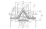
- FIG. 3 is a cross-sectional view taken along line 3-3 in FIG. Sectional drawing which shows the example of a change of arrangement
- (A), (b) is sectional drawing of the vehicle antenna apparatus of the prior art example of the state accommodated in the antenna cover part.
- the “front-rear direction” corresponds to the front-rear direction of the vehicle 10
- the “up-down direction” corresponds to the height direction of the vehicle 10.
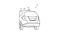
- the roof panel 20 constitutes a roof 11 of the vehicle 10.
- the roof panel 20 is made of resin.
- the roof panel 20 includes a roof portion 21 and an antenna cover portion 22 that protrudes from the roof portion 21.
- the roof panel 20 is an integrally molded product including a roof portion 21 and an antenna cover portion 22.
- the roof panel 20 will be described.
- the roof panel 20 is manufactured by two-color molding of the first molding part 23 and the second molding part 24.
- the first molding part 23 is made of a transmissive material
- the second molding part 24 is made of an impermeable material.
- the first molding part 23 is located outside the vehicle 10 with respect to the second molding part 24, while the second molding part 24 is the first molding part 23.
- the surface of the first molding portion 23 located outside the vehicle 10 with the roof panel 20 attached to the vehicle 10 is on the outer surface of the roof panel 20, that is, the outer surface 21 a of the roof portion 21 and the outer surface 22 a of the antenna cover portion 22. Equivalent to.
- the surface of the second molding portion 24 located inside the vehicle 10 with the roof panel 20 attached to the vehicle 10 is the inner surface of the roof panel 20, that is, the inner surface 21b of the roof portion 21 and the inner surface of the antenna cover portion 22. This corresponds to 22b.
- the roof part 21 will be described. As shown in FIGS. 2 and 3, the roof portion 21 is a portion where the antenna cover portion 22 is not formed on the roof panel 20.
- the antenna cover part 22 will be described. As shown in FIG. 1, the antenna cover portion 22 is located in the rear portion of the roof panel 20 and at the approximate center in the vehicle width direction. As shown in FIGS. 2 and 3, the antenna cover portion 22 protrudes from the outer surface 21 a of the roof portion 21 toward the outside of the vehicle 10 and has an internal space S. The curvature of the roof portion 21 and the curvature of the antenna cover portion 22 are different. Further, a boundary portion between the outer surface 21a of the roof portion 21 and the outer surface 22a of the antenna cover portion 22 is defined as an outer raised start point R1. Further, a boundary portion between the inner surface 21b of the roof portion 21 and the inner surface 22b of the antenna cover portion 22 is defined as an inner raised start point R2.
- the antenna in this embodiment is a so-called shark fin antenna.
- the antenna cover portion 22 according to this embodiment has a substantially triangular shape (specifically, a right triangle shape as shown in FIG. 2) in cross-sectional view in the front-rear direction of the vehicle 10, and a cross-sectional view in the vehicle width direction. Is a substantially triangular shape (specifically, an isosceles triangular shape as shown in FIG. 3) whose area increases toward the lower side of the vehicle 10.
- the antenna cover portion 22 in this embodiment has a substantially triangular pyramid shape whose cross-sectional area increases from the top to the bottom.
- the line extending along the outer bulge starting point R1 forms a triangle (isosceles triangle).
- the line extending along the inner raised start point R2 forms a triangle (isosceles triangle).
- the vehicle antenna device 30 is attached to the roof panel 20 below the portion of the inner surface 21 b of the roof portion 21 that is located at the foremost side of the vehicle 10 in the outer raised starting point R ⁇ b> 1.
- a mounting portion 25 for mounting is provided.
- the attachment portion 25 is a round boss, and extends downward from the inner surface 21b of the roof portion 21.
- the attachment portion 25 is a part of the second molding portion 24 and is integrally molded with the roof portion 21 (roof panel 20). Further, the tip 25 a of the attachment portion 25 is substantially parallel to the roof portion 21.
- the vehicular antenna device 30 includes a base portion 31 and a first antenna component 32 as a standing portion.
- the base portion 31 includes a bottom plate 311 and a substrate 312 having the same shape as the bottom plate 311 in plan view.
- a base plate 31 is formed by laminating a substrate 312 above the bottom plate 311.
- the base portion 31 is a rectangular flat plate having a long side and a short side in a plan view, and functions as a base for attaching the first antenna component 32 to the vehicle 10.
- An antenna unit is configured by the vehicle antenna device 30 and the antenna cover portion 22 that accommodates the entire vehicle antenna device 30, and the antenna unit is attached to the roof panel 20 of the vehicle 10.
- the first antenna component 32 extends from the base portion 31 upward (in a direction intersecting the base portion 31), that is, in the internal space S of the antenna cover portion 22.
- a second antenna component 34 is mounted in front of the first antenna component 32 in the base portion 31.
- the first antenna component 32 and the second antenna component 34 cause the vehicle antenna device 30 to function as an antenna.
- the first antenna component 32 in this embodiment has a longer protruding length from the base portion 31 than the second antenna component 34.
- the width of the first antenna component 32 is smaller than the width of the base portion 31 in the vehicle width direction.
- the entire first antenna component 32 may be an antenna element or a substrate on which the antenna element is mounted. That is, the first antenna component 32 is a member that stands up from the base portion 31 and includes at least an antenna element.
- the vehicle antenna device 30 is arranged in the vehicle 10 so that the vehicle width direction and the short side direction of the base portion 31 are the same direction. Further, the first antenna component 32 is disposed on the base portion 31 so that the plate thickness direction of the first antenna component 32 is orthogonal to the plate thickness direction of the base portion 31.
- the length of the base portion 31 in the short side direction (the width of the base portion 31) is set to “length L 1”, and the first antenna component 32 is disposed above the base portion 31. Assume a region extending along the standing direction and having a width of length L1. In this embodiment, the first antenna component 32 and the second antenna component 34 are within the region having the width of the length L1 described above and do not protrude outside the region. That is, as shown in FIG. 3, in the vehicle antenna device 30 of this embodiment, when the vehicle antenna device 30 is viewed from the front, both ends of the base portion 31 in the short side direction (the base portion 31 along the long side). The two end portions are located on the outermost side.
- an insertion hole 31 a is formed in the end portion (front end portion) of the base portion 31 in the front direction of the vehicle 10.
- the bottom plate 311 and the substrate 312 each have a hole penetrating in the thickness direction, and these two holes constitute one insertion hole 31a.
- an interior panel 40 that constitutes the interior of the vehicle 10 is located below the roof panel 20 and below the base portion 31 of the vehicle antenna device 30 attached to the vehicle 10. It is attached.
- the alternate long and short dash line shown in FIG. 3 is for explaining the vehicular antenna device 51 in the related art (see FIGS. 6A and 6B) as a comparative example.
- the antenna cover part 52 in a prior art and the antenna cover part 22 in embodiment are made similar. Therefore, the opening angle ⁇ at the apex of the antenna cover portion 52 in the conventional technique and the opening angle ⁇ at the apex of the antenna cover portion 22 in the embodiment are the same angle.
- the distance between the outer raised start point portions R ⁇ b> 1 facing each other in the vehicle width direction is defined as the outer dimension of the antenna cover portion 22 in the vehicle width direction.
- the outer dimension of the antenna cover portion 22 is defined as “length L2”.
- the length between the intersection point K1 and the intersection point K2 between the virtual line X and the inner surface of the antenna cover portion 22 is determined in the vehicle width direction. Is defined as the inner dimension of the antenna cover portion 22.
- the inner dimension of the antenna cover portion 22 is defined as “length L3”. Further, as shown in FIG.
- the outer dimension of the antenna cover portion 52 in the prior art indicated by the alternate long and short dash line is defined as “length L4”.
- the length L2 and the length L3 are values that can vary depending on the planar shape of the antenna cover portion 22 when viewed from above the vehicle 10 and the cross-sectional position of the planar shape in the front-rear direction.
- the shape of the antenna cover part when viewed in plan is substantially elliptical, and the antenna cover part is arranged so that the longitudinal direction of the vehicle and the major axis direction of the ellipse are in the same direction. In this case, the closer to the end of the ellipse in the front-rear direction, the shorter the length L2 and the length L3, while the longer the center of the ellipse, the longer the length L2 and the length L3.
- a boundary portion between the outer surface 21a of the roof portion 21 and the outer surface 22a of the antenna cover portion 22, that is, a boundary line R11 along the outer raised start point R1 is assumed.
- the boundary line R11 can be viewed endlessly (triangular) when the vehicle 10 is viewed from above.
- the outer virtual surface 21c which has the boundary line R11 as an outline and becomes the same curvature as the outer surface 21a is assumed.
- a boundary portion between the inner surface 21b of the roof portion 21 and the inner surface 22b of the antenna cover portion 22, that is, a boundary line R22 along the inner raised start point R2 is assumed.
- the boundary line R22 can be viewed endlessly (triangular) when the vehicle 10 is viewed from above. Then, an inner virtual surface 21d having a boundary line R22 as an outline and having the same curvature as the inner surface 21b is assumed.
- the outer virtual surface 21c is a surface including the boundary line R11
- the inner virtual surface 21d is a surface including the boundary line R22.
- the base portion 53 of the vehicular antenna device 51 is attached at the same position in the vertical direction as the outer surface 21 a of the roof portion 21 (the position of the outer virtual surface 21 c). (Refer to the positions shown in FIGS. 6A and 6B).
- the protruding length of the base portion 53 from the outer virtual surface 21c in the prior art is defined as “length M1”. “Length M 1” is the same as the plate thickness of the base portion 53.
- the widthwise end portion of one surface of the base portion 53 (hereinafter referred to as the outer surface 53b) that is farthest from the outer virtual surface 21c contacts the inner side of the antenna cover portion 52.
- the following length relationship is set so as not to touch. That is, in order to secure a space for accommodating the base portion 53 in the antenna cover portion 52, the inner dimension of the antenna cover portion 52 is longer than the length of the base portion 53 in the short side direction. If the thickness of the antenna cover portion 52 does not change regardless of the position of the base portion 53 in the vertical direction, the outer size (length) of the antenna cover portion 52 increases as the inner size of the antenna cover portion 52 increases. L4) also becomes longer. That is, the outer dimension (L4) of the antenna cover part 52 in the prior art is longer than the outer dimension (length L2) of the antenna cover part 22 in the embodiment. As the outer dimension of the antenna cover 52 increases, the internal space of the antenna cover 52 also increases.
- the mounting portion 25 is erected from below the outer virtual surface 21 c with respect to the insertion hole 31 a of the base portion 31 and the mounting portion 25 of the antenna cover portion 22. Screws B are inserted along the direction, and the vehicle antenna device 30 is attached to the roof panel 20 from the inside of the roof panel 20.
- the first antenna component 32 is accommodated in the internal space S of the antenna cover portion 22.
- the entire base portion 31 attached to the vehicle 10 via the attachment portion 25 is not positioned above the outer virtual surface 21c.
- the protruding length of the base portion 31 from the outer virtual surface 21c in the embodiment is shorter than the protruding length of the base portion 53 from the outer virtual surface 21c in the prior art.
- the base portion 31 does not protrude from the outer virtual surface 21c (the protrusion length is “0”).
- the projecting length of the base portion 31 from the outer virtual surface 21c is shortened, so that the internal space S for accommodating the base portion 31 in the antenna cover portion 22 is made smaller than the internal space in the prior art. Can do.
- the outer dimension of the antenna cover part 22 can be shortened.
- the entire antenna cover portion 22 can be reduced in size as compared with the case where the vehicle antenna device 51 is attached to the outer surface of the roof 101 as in the prior art.
- the outer surface 31b of the base portion 31 is located below the outer virtual surface 21c and below the inner virtual surface 21d.
- the base portion 31 does not protrude upward from the outer virtual surface 21c, it is not necessary to secure a space for accommodating the base portion 31 in the antenna cover portion 22. Therefore, the outer dimension of the antenna cover part 22 can be further shortened. As a result, the entire antenna cover portion 22 can be further reduced in size.
- the following effects can be obtained. (1) When at least a part of the base portion 31 is located below the outer virtual surface 21c, the outer side is larger than when the entire base portion 31 is located above the outer virtual surface 21c. The protruding length of the base portion 31 from the virtual surface 21c is shortened. Thereby, the internal space S of the antenna cover part 22 for accommodating the vehicle antenna device 30 can be reduced in size. Assuming that the thickness of the antenna cover portion 22 does not change regardless of the vertical position of the base portion 31, if the internal space S for accommodating the base portion 31 in the antenna cover portion 22 becomes smaller, the antenna cover accordingly Since the outer dimension of the part 22 can also be shortened, as a result, the whole antenna cover part 22 can be reduced in size.
- the aerodynamic performance of the vehicle 10 can be improved by downsizing the entire antenna cover portion 22.
- the appearance of the entire antenna cover 22 can be improved.
- the roof portion and the antenna cover portion are separate members (for example, see Patent Document 1), and when the vehicle antenna device is attached from the outer surface of the roof portion, the vehicle antenna device is fixed to the outer surface of the roof portion. And a seal member for closing a gap generated between the roof portion and the antenna cover portion are required.
- the vehicle antenna device 30 can be attached from the inside of the roof panel 20, and it is not necessary to attach from the outside of the vehicle 10. Therefore, parts such as a member and a sealing material for fixing the vehicle antenna device 30 to the outer surface 21a of the roof portion 21 are not necessary, and as a result, the cost required for mounting the vehicle antenna device 30 can be reduced.
- the mounting portion 25 is integrally formed with the roof portion 21 (roof panel 20), the number of parts related to mounting of the vehicle antenna device 30 can be reduced. Moreover, since the roof part 21 (roof panel 20) and the attachment part 25 can be integrally molded by resin molding, the position of the attachment part 25 does not differ for every product, and the positional accuracy of the attachment part 25 is improved. You can also. By increasing the positional accuracy of the mounting portion 25, the positional accuracy of the vehicle antenna device 30 can be increased. Accordingly, it is possible to prevent the vehicle antenna device 30 from being accommodated in the antenna cover portion 22 due to contact between the antenna cover portion 22 and the vehicle antenna device 30.
- the attachment portion 25 extends downward from the inner surface 21b of the roof portion 21. Further, the tip 25 a of the attachment portion 25 is substantially parallel to the roof portion 21. For this reason, the base part 31 attached to the vehicle 10 via the attachment part 25 is in contact with the tip 25a of the attachment part 25 and is substantially parallel to the roof part 21. Further, the entire base portion 31 is located below the outer virtual surface 21c and below the inner virtual surface 21d. In such a case, since the base portion 31 does not protrude above the outer virtual surface 21c, it is not necessary to secure the internal space S for accommodating the base portion 31 in the antenna cover portion 22. Therefore, the outer dimension of the antenna cover part 22 can be shortened compared with the case where the base part 31 is located above the outer virtual surface 21c. As a result, the entire antenna cover portion 22 can be further reduced in size.
- the attachment portion may have any shape.
- the position of the attachment portion is not limited to the position of the embodiment.
- the attachment portion may be located below a position located on the farthest rear side of the vehicle 10 in the outer bulge start point R1.
- the attaching part may be located on the base part 31.
- an attachment portion that protrudes from the outer surface 31 b in the height direction of the vehicle 10 may be formed on the outer surface 31 b of the base portion 31.
- the mounting portion 25 and the roof portion 21 may be formed as separate members without being integrally formed. That is, the attachment part 25 which is a member different from the roof panel 20 may be attached to the roof panel 20 which does not have the attachment part 25.
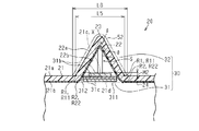
- the vehicle antenna device 30 may not have the second antenna component 34. As shown in FIG. 3, it is not necessary that the entire base portion 31 of the vehicle antenna device 30 is positioned below the outer virtual surface 21c, and a part of the base portion 31 is less than the outer virtual surface 21c. As long as it is located below. For example, as shown by the solid line in FIG. 4, the inner surface (lower surface) 31c of the base portion 31 is positioned above the inner virtual surface 21d, but the outer surface (upper surface) 31b of the base portion 31 is the outer virtual surface. What is necessary is just to be located below 21c. Moreover, the outer surface 31b of the base part 31 may be located in the position shown with the dashed-dotted line of FIG.
- the outer surface 31b of the base portion 31 is positioned above the outer virtual surface 21c, but the inner surface 31c of the base portion 31 only needs to be positioned lower than the outer virtual surface 21c.
- the protruding length of the base portion 31 from the outer virtual surface 21c is “length M2” shorter than “length M1”.
- the outer dimension of the antenna cover portion 22 in the vehicle width direction is “length L5”, while in the example indicated by the alternate long and short dash line, the outer dimension of the antenna cover portion 22 in the vehicle width direction is “long”. L6 ”.
- the internal space S for accommodating the base portion 31 in the antenna cover portion 22 is reduced by the amount that the base portion 31 is located below the outer virtual surface 21c.
- the length L5 is shorter than the length L6.
- the entire base portion 31 of the vehicular antenna device 30 does not have to be positioned below the outer virtual surface 21c, and a part of the base portion 31 is closer to the outer virtual surface 21c. As long as it is located below.
- the tip 25 a of the attachment portion 25 is inclined obliquely upward toward the rear direction of the vehicle 10
- the base portion 31 attached to the vehicle 10 via the attachment portion 25 is It is attached so as to be inclined obliquely upward toward the rear direction of the vehicle 10.
- the front portion of the base portion 31 is located below the outer virtual surface 21c, but the rear portion of the base portion 31 is located above the outer virtual surface 21c.
- the roof portion 21 and the antenna cover portion 22 may be formed separately, without being integrally formed. Even when the roof portion 21 and the antenna cover portion 22 are separately formed, the vehicle antenna device 30 is arranged such that at least a part of the base portion 31 of the vehicle antenna device 30 is positioned below the outer virtual surface 21c. Is preferably attached to the roof portion 21. For example, a concave portion is provided in the roof portion 21, and after the vehicle antenna device 30 is attached so that the base portion 31 of the vehicle antenna device 30 contacts the bottom portion of the concave portion, the antenna cover portion 22 is attached to the outside of the roof portion 21. You may make it attach from. Moreover, the roof part 21 and the antenna cover part 22 may be shape
- the position of the upper end of the antenna cover portion (the position of the upper end of the antenna cover 52 shown by the one-dot chain line in FIG. 3) when the entire base portion is located above the outer virtual surface 21c, and at least the base portion 31
- the position of the upper end of the antenna cover part 22 when a part is located below the outer virtual surface 21c may be the same.
- the base portion is larger than when the entire base portion is positioned above the outer virtual surface 21c.
- the protruding length of the first antenna component 32 from 31 can be increased.
- the height of the antenna cover part 22 does not change, since the width
- the dimension in the vehicle width direction of the board 312 may be shorter than the bottom plate 311.
- the board 312 is shorter in the vehicle width direction than the bottom plate 311, so that the end in the width direction of the board 312 does not contact the inside of the antenna cover portion 22. Therefore, it is only necessary to secure a space for accommodating the base portion 31 in the antenna cover portion 22 so that the width direction end portion of the bottom plate 311 does not contact the inside of the antenna cover portion 22. That is, in the base portion 31, the dimension in the vehicle width direction is the longest, because it is the bottom plate 311, and the width direction end portion of the bottom plate 311 may be prevented from coming into contact with the antenna cover portion 22.
- the base unit 31 may be composed of only the substrate 312.
- the dimension in the front-rear direction of the substrate 312 (the dimension in the long side direction in the embodiment) may be shorter than the dimension in the front-rear direction of the bottom plate 311.
- the board 312 may not face the mounting portion 25, and the insertion hole 31 a through which the screw B is inserted may be a hole provided only in the bottom plate 311.
- the shape of the antenna cover portion 22 is the same as the shape shown in FIG. 6B, while the opening angle ⁇ is the same regardless of the protruding length of the base portion 31 from the outer virtual surface 21c, while the outer virtual surface 21c.
- the outer dimensions of the antenna cover portion 22 in the vicinity of the base portion 31 may be varied in accordance with the protruding length of the base portion 31 from the base.
- the shape of the antenna cover portion 22 may be changed by changing the opening angle ⁇ according to the protruding length of the base portion 31 from the outer virtual surface 21c. If the example demonstrated in FIG. 3 is used, you may make opening angle (theta) shown as a continuous line smaller than opening angle (theta) in the example shown with a dashed-dotted line. As the protrusion length of the base portion 31 from the outer virtual surface 21c is shorter, the opening angle ⁇ can be narrowed. As a result, the outer dimension of the antenna cover portion 22 can be shortened.
- the roof panel 20 may be formed of a material other than resin (for example, a metal material).
- the antenna cover portion 22 is preferably formed of a material that does not hinder the transmission and reception of radio waves.
- the roof panel 20 may be movable.
- an opening is provided in the roof 11, and a support portion that supports the roof panel 20 is formed at the edge in the vehicle width direction of the opening.
- close the opening part by making the roof panel 20 movable with respect to an opening part.
- the roof panel 20 and the antenna cover part 22 can be integrated.
- the rear part of the roof 11 may be a resin panel, while the remaining part of the roof 11 may be made of a metal plate. Moreover, while only the minimum area where the vehicle antenna device 30 is attached to the rear part of the roof 11 is made of a resin panel, the remaining part of the roof 11 may be made of a metal plate.
- the roof panel 20 and the rear window may be integrated into a resin panel. Further, when the vehicle antenna device 30 is attached to the rear portion of the roof 11, the rear portion of the roof 11 and the rear window are integrated into a resin panel, while the remaining portion of the roof 11 may be formed of a metal plate. Good. Further, a minimum area to which the vehicle antenna device 30 at the rear portion of the roof 11 is attached and the rear window are integrated to form a resin panel, while the remaining portion of the roof 11 may be formed of a metal plate. .
- the roof panel 20 may be configured by single color molding. (Circle) the roof panel 20 may have the transparency with respect to light. Further, it does not have to be light transmissive.
- the mounting position of the vehicle antenna device 30 is not limited to the rear portion of the vehicle 10.
- it may be attached to the front portion of the vehicle 10 or may be attached to the approximate center of the roof 11.
- the roof panel includes a roof portion and an antenna cover portion that protrudes from the roof portion and has an internal space.
- the antenna device includes a base portion and a standing portion extending from the base portion into the internal space of the antenna cover portion, and the roof panel is made of resin, and the roof portion and the antenna cover The part is an integrally molded vehicle.
- the roof part and the antenna cover part are separate members (for example, refer to Patent Document 1)
- a sealing member or the like for closing is necessary, and it takes time and effort to attach, or the cost for attaching increases.
- the roof portion and the antenna cover portion are integrally formed, the base portion of the vehicle antenna device may be positioned above the outer virtual surface.
Landscapes
- Engineering & Computer Science (AREA)
- Remote Sensing (AREA)
- Mechanical Engineering (AREA)
- Support Of Aerials (AREA)
- Fittings On The Vehicle Exterior For Carrying Loads, And Devices For Holding Or Mounting Articles (AREA)
- Details Of Aerials (AREA)
Abstract
車両は、ルーフパネルと、車両用アンテナ装置と、を備える。ルーフパネルは、ルーフ部と、該ルーフ部から隆起し、内部空間を有するアンテナカバー部と、を有する。車両用アンテナ装置は、ベース部と、該ベース部からアンテナカバー部の内部空間内に延びる立設部と、を有する。ルーフ部の外面とアンテナカバー部の外面との境界部分に位置する境界線に沿った外側仮想面を想定した場合、車両用アンテナ装置が車両へ取り付けられた状態において、ベース部の少なくとも一部は、外側仮想面よりも下方に位置している。
Description
本発明は、車両用アンテナ装置を備えた車両及び車両用アンテナ装置に関する。
従来、車両には、AM/FMラジオ放送、テレビ放送、GPS等を利用するための車両用アンテナ装置が取り付けられている。車両用アンテナ装置は、見通しがよく、車両の最も高い位置にあるルーフに取り付けられていることが多い。
図6(a)及び図6(b)に示すように、特許文献1に記載の車両用アンテナ装置51は、ベース部53と、ベース部53から上方に延びる立設部54と、を有している。そして、車両用アンテナ装置51と、該車両用アンテナ装置51全体を収容するアンテナカバー部52と、によって、アンテナユニット50が構成されており、アンテナユニット50が車両のルーフ101に取り付けられている。
特許文献1のアンテナユニット50では、ベース部53が車両のルーフ101に取り付けられているため、ベース部53全体を収容するためにアンテナカバー部52が大型化してしまうという問題点があった。
この発明の目的は、アンテナカバー部を小型化することが可能な車両用アンテナ装置及びそうした車両用アンテナ装置を備える車両を提供することにある。
上記問題点を解決するための車両は、ルーフパネルと、車両用アンテナ装置と、を備えた車両において、前記ルーフパネルは、ルーフ部と、該ルーフ部から隆起し、内部空間を有するアンテナカバー部と、を有し、前記車両用アンテナ装置は、ベース部と、該ベース部から前記アンテナカバー部の前記内部空間内に延びる立設部と、を有し、前記ルーフ部の外面と前記アンテナカバー部の外面との境界部分に位置する境界線に沿った外側仮想面を想定した場合、前記車両用アンテナ装置が前記車両へ取り付けられた状態において、前記ベース部の少なくとも一部は、前記外側仮想面よりも下方に位置している。
上記問題点を解決するための車両用アンテナ装置は、ルーフパネルを備える車両に取り付けられる車両用アンテナ装置であって、前記ルーフパネルがルーフ部、及び該ルーフ部から隆起し、内部空間を有するアンテナカバー部を有し、前記車両用アンテナ装置は、ベース部と、該ベース部から前記アンテナカバー部の前記内部空間内に延びる立設部と、を有し、前記ルーフ部の外面と前記アンテナカバー部の外面との境界部分に位置する境界線に沿った外側仮想面を想定した場合、前記車両用アンテナ装置が前記車両へ取り付けられた状態において、前記ベース部の少なくとも一部は、前記外側仮想面よりも下方に位置する。
以下、車両10及び車両用アンテナ装置30の一実施形態を図面に従って説明する。なお、以下の説明において、「前後方向」とは、車両10の前後方向に相当し、「上下方向」とは、車両10の高さ方向に相当する。
図1に示すように、ルーフパネル20は、車両10のルーフ11を構成している。ルーフパネル20は、樹脂製である。
図2に示すように、ルーフパネル20は、ルーフ部21と、ルーフ部21から隆起するアンテナカバー部22と、を有する。ルーフパネル20は、ルーフ部21とアンテナカバー部22とを含む一体成形品である。
図2に示すように、ルーフパネル20は、ルーフ部21と、ルーフ部21から隆起するアンテナカバー部22と、を有する。ルーフパネル20は、ルーフ部21とアンテナカバー部22とを含む一体成形品である。
ルーフパネル20について説明する。
ルーフパネル20は、第1成形部23と第2成形部24との二色成形によって製造されている。光に関して、第1成形部23は透過材製であり、第2成形部24は不透過材製である。車両10にルーフパネル20が取り付けられた状態において、第1成形部23は、第2成形部24よりも車両10の外側に位置している一方、第2成形部24は、第1成形部23よりも車両10の内側に位置している。車両10にルーフパネル20が取り付けられた状態で車両10の外側に位置する第1成形部23の面が、ルーフパネル20の外面、すなわちルーフ部21の外面21a及びアンテナカバー部22の外面22aに相当する。また、車両10にルーフパネル20が取り付けられた状態で車両10の内側に位置する第2成形部24の面が、ルーフパネル20の内面、すなわちルーフ部21の内面21b及びアンテナカバー部22の内面22bに相当する。
ルーフパネル20は、第1成形部23と第2成形部24との二色成形によって製造されている。光に関して、第1成形部23は透過材製であり、第2成形部24は不透過材製である。車両10にルーフパネル20が取り付けられた状態において、第1成形部23は、第2成形部24よりも車両10の外側に位置している一方、第2成形部24は、第1成形部23よりも車両10の内側に位置している。車両10にルーフパネル20が取り付けられた状態で車両10の外側に位置する第1成形部23の面が、ルーフパネル20の外面、すなわちルーフ部21の外面21a及びアンテナカバー部22の外面22aに相当する。また、車両10にルーフパネル20が取り付けられた状態で車両10の内側に位置する第2成形部24の面が、ルーフパネル20の内面、すなわちルーフ部21の内面21b及びアンテナカバー部22の内面22bに相当する。
ルーフ部21について説明する。
図2及び図3に示すように、ルーフ部21は、ルーフパネル20においてアンテナカバー部22が形成されていない部位である。
図2及び図3に示すように、ルーフ部21は、ルーフパネル20においてアンテナカバー部22が形成されていない部位である。
アンテナカバー部22について説明する。
図1に示すように、アンテナカバー部22は、ルーフパネル20の後部であって、車幅方向における略中央に位置している。図2及び図3に示すように、アンテナカバー部22は、ルーフ部21の外面21aから車両10の外側に向かって隆起しており、内部空間Sを有している。ルーフ部21の曲率とアンテナカバー部22の曲率とは異なっている。また、ルーフ部21の外面21aとアンテナカバー部22の外面22aとの境界部分を、外側隆起始点部R1とする。また、ルーフ部21の内面21bとアンテナカバー部22の内面22bとの境界部分を、内側隆起始点部R2とする。
図1に示すように、アンテナカバー部22は、ルーフパネル20の後部であって、車幅方向における略中央に位置している。図2及び図3に示すように、アンテナカバー部22は、ルーフ部21の外面21aから車両10の外側に向かって隆起しており、内部空間Sを有している。ルーフ部21の曲率とアンテナカバー部22の曲率とは異なっている。また、ルーフ部21の外面21aとアンテナカバー部22の外面22aとの境界部分を、外側隆起始点部R1とする。また、ルーフ部21の内面21bとアンテナカバー部22の内面22bとの境界部分を、内側隆起始点部R2とする。
この実施形態におけるアンテナは、所謂、シャークフィンアンテナである。そして、この実施形態におけるアンテナカバー部22は、車両10の前後方向における断面視が略三角形状(具体的には、図2に示すように直角三角形状)であるとともに、車幅方向における断面視が車両10の下方に向かうほど面積が大きくなる略三角形状(具体的には、図3に示すように二等辺三角形状)である。言い換えれば、この実施形態におけるアンテナカバー部22は、上方から下方に向かうにつれて断面積が大きくなる略三角錐状である。外側隆起始点部R1に沿って延びる線は三角形(二等辺三角形)を形成する。内側隆起始点部R2に沿って延びる線も同様に三角形(二等辺三角形)を形成する。
また、図2に示すように、ルーフ部21の内面21bであって、外側隆起始点部R1のうち車両10の最も前側に位置する箇所の下方には、車両用アンテナ装置30をルーフパネル20に取り付けるための取付部25が設けられている。取付部25は、丸ボスであって、ルーフ部21の内面21bから下方に向かって延びている。また、取付部25は、第2成形部24の一部であって、ルーフ部21(ルーフパネル20)と一体成形されている。また、取付部25の先端25aは、ルーフ部21と略平行となっている。
車両用アンテナ装置30は、ベース部31と、立設部としての第1アンテナ部品32と、を有する。
図2に示すように、ベース部31は、底板311と、平面視での形状が底板311と同一である基板312とを有する。底板311の上方に基板312が積層されて、ベース部31が形成されている。ベース部31は、平面視の状態において長辺と短辺を持つ長方形状の平板であり、第1アンテナ部品32を車両10に取り付けるための基台として機能する。車両用アンテナ装置30と、該車両用アンテナ装置30全体を収容するアンテナカバー部22と、によって、アンテナユニットが構成されており、アンテナユニットが車両10のルーフパネル20に取り付けられている。
図2に示すように、ベース部31は、底板311と、平面視での形状が底板311と同一である基板312とを有する。底板311の上方に基板312が積層されて、ベース部31が形成されている。ベース部31は、平面視の状態において長辺と短辺を持つ長方形状の平板であり、第1アンテナ部品32を車両10に取り付けるための基台として機能する。車両用アンテナ装置30と、該車両用アンテナ装置30全体を収容するアンテナカバー部22と、によって、アンテナユニットが構成されており、アンテナユニットが車両10のルーフパネル20に取り付けられている。
ベース部31からは、上方(ベース部31に対して交差する方向)に、つまりアンテナカバー部22の内部空間S内に、第1アンテナ部品32が延びている。また、ベース部31において第1アンテナ部品32よりも前方には、第2アンテナ部品34が実装されている。第1アンテナ部品32及び第2アンテナ部品34は、車両用アンテナ装置30をアンテナとして機能させる。なお、この実施形態における第1アンテナ部品32は、第2アンテナ部品34よりもベース部31からの突出長が長い。また、車幅方向において、第1アンテナ部品32の幅は、ベース部31の幅よりも小さい。ちなみに、第1アンテナ部品32は、全体がアンテナ素子であってもよいし、アンテナ素子が実装された基板であってもよい。すなわち、第1アンテナ部品32とは、ベース部31から起立する部材であり、少なくとも、アンテナ素子を含む部材である。
この実施形態では、車幅方向とベース部31の短辺方向とが同じ方向となるように車両用アンテナ装置30が車両10に配置されている。また、第1アンテナ部品32の板厚方向が、ベース部31の板厚方向と直交するように、第1アンテナ部品32がベース部31に配置されている。
ここで、図3に示すように、ベース部31の短辺方向の長さ(ベース部31の幅)を「長さL1」とするとともに、ベース部31の上方に、第1アンテナ部品32の立設方向に沿って延びる、長さL1分の幅を有する領域を想定する。そして、この実施形態において第1アンテナ部品32及び第2アンテナ部品34は、前述した長さL1分の幅を有する領域内に収まり、当該領域外へはみ出していない。つまり、図3に示すように、この実施形態の車両用アンテナ装置30では、車両用アンテナ装置30を正面視した場合において、ベース部31の短辺方向の両端部(長辺に沿うベース部31の両端部)が最も外方に位置していることになる。
また、図2に示すように、車両10の前方向におけるベース部31の端部(前端部)には、挿通孔31aが形成されている。詳細にいえば、底板311と基板312は、それぞれ、厚み方向に貫通する孔を有しており、これらの二つの孔は一つの挿通孔31aを構成している。
また、車両10において、ルーフパネル20よりも下方であって、車両10に取り付けられた状態における車両用アンテナ装置30のベース部31よりも下方には、車両10の内装を構成する内装パネル40が取り付けられている。
以下、図2及び図3に従って、アンテナカバー部22に車両用アンテナ装置30を収容する方法を、従来技術と比較しつつ、その作用とともに説明する。
なお、図3に示す一点鎖線は、比較例としての従来技術(図6(a)及び図6(b)参照)における車両用アンテナ装置51を説明するためのものである。また、説明を簡略化するために、従来技術におけるアンテナカバー部52と、実施形態におけるアンテナカバー部22とを、相似化している。そのため、従来技術におけるアンテナカバー部52の頂点の開口角度θと、実施形態におけるアンテナカバー部22の頂点の開口角度θとは、同一角度となる。
なお、図3に示す一点鎖線は、比較例としての従来技術(図6(a)及び図6(b)参照)における車両用アンテナ装置51を説明するためのものである。また、説明を簡略化するために、従来技術におけるアンテナカバー部52と、実施形態におけるアンテナカバー部22とを、相似化している。そのため、従来技術におけるアンテナカバー部52の頂点の開口角度θと、実施形態におけるアンテナカバー部22の頂点の開口角度θとは、同一角度となる。
まず、各部材の寸法について説明する。
図3に示すように、この実施形態では、車幅方向において対向する外側隆起始点部R1間の距離を、車幅方向におけるアンテナカバー部22の外寸と定義する。そして、アンテナカバー部22の外寸を、「長さL2」と定義する。また、車幅方向において対向する外側隆起始点部R1同士を結ぶ仮想線Xを想定した場合、仮想線Xとアンテナカバー部22の内面との交点K1及び交点K2間の長さを、車幅方向におけるアンテナカバー部22の内寸と定義する。そして、アンテナカバー部22の内寸を、「長さL3」と定義する。また、図3に示すように、一点鎖線で示す従来技術におけるアンテナカバー部52の外寸を、「長さL4」と定義する。なお、長さL2及び長さL3は、アンテナカバー部22を車両10の上方から平面視したときにおける平面形状と、その平面形状の前後方向における断面位置とによって変動し得る値である。例えば、アンテナカバー部を平面視したときの形状を略楕円形状とし、車両の前後方向と楕円の長径方向とが同一方向となるようにアンテナカバー部を配置したとする。この場合、前後方向において楕円の端部に近付くほど、長さL2及び長さL3は短くなる一方、楕円の中央ほど、長さL2及び長さL3は長くなる。
図3に示すように、この実施形態では、車幅方向において対向する外側隆起始点部R1間の距離を、車幅方向におけるアンテナカバー部22の外寸と定義する。そして、アンテナカバー部22の外寸を、「長さL2」と定義する。また、車幅方向において対向する外側隆起始点部R1同士を結ぶ仮想線Xを想定した場合、仮想線Xとアンテナカバー部22の内面との交点K1及び交点K2間の長さを、車幅方向におけるアンテナカバー部22の内寸と定義する。そして、アンテナカバー部22の内寸を、「長さL3」と定義する。また、図3に示すように、一点鎖線で示す従来技術におけるアンテナカバー部52の外寸を、「長さL4」と定義する。なお、長さL2及び長さL3は、アンテナカバー部22を車両10の上方から平面視したときにおける平面形状と、その平面形状の前後方向における断面位置とによって変動し得る値である。例えば、アンテナカバー部を平面視したときの形状を略楕円形状とし、車両の前後方向と楕円の長径方向とが同一方向となるようにアンテナカバー部を配置したとする。この場合、前後方向において楕円の端部に近付くほど、長さL2及び長さL3は短くなる一方、楕円の中央ほど、長さL2及び長さL3は長くなる。
また、図2及び図3に示すように、ルーフ部21の外面21aとアンテナカバー部22の外面22aとの境界部分、すなわち外側隆起始点部R1に沿う境界線R11を想定する。境界線R11は、車両10を上方から平面視したときに無端状(三角形状)に視認可能である。そして、境界線R11を輪郭として有し、かつ外面21aと同一曲率となる外側仮想面21cを想定する。同様に、ルーフ部21の内面21bとアンテナカバー部22の内面22bとの境界部分、すなわち内側隆起始点部R2に沿う境界線R22を想定する。境界線R22は、車両10を上方から平面視したときに無端状(三角形状)に視認可能である。そして、境界線R22を輪郭として有し、かつ内面21bと同一曲率となる内側仮想面21dを想定する。概略的に言えば、外側仮想面21cは境界線R11を含む面であり、内側仮想面21dは境界線R22を含む面である。
図3の一点鎖線で示すように、従来技術では、ルーフ部21の外面21aと上下方向において同じ位置(外側仮想面21cの位置)に、車両用アンテナ装置51のベース部53が取り付けられている(図6(a)及び図6(b)に示す位置参照)。以下、従来技術における外側仮想面21cからのベース部53の突出長を、「長さM1」と定義する。「長さM1」は、ベース部53の板厚と同じである。
また、従来技術の車両用アンテナ装置51では、外側仮想面21cから最も離れた位置にあるベース部53の一面(以下、外面53bと示す)の幅方向端部がアンテナカバー部52の内側に当接しないように、次のような長さ関係が設定されている。すなわち、アンテナカバー部52においてベース部53を収容するための空間を確保するために、アンテナカバー部52の内寸は、ベース部53の短辺方向の長さよりも長くなっている。また、ベース部53の上下方向の位置にかかわらず、アンテナカバー部52の厚みが変化しないとすると、アンテナカバー部52の内寸が長くなることに伴い、アンテナカバー部52の外寸(長さL4)も長くなる。つまり、従来技術におけるアンテナカバー部52の外寸(L4)は、実施形態におけるアンテナカバー部22の外寸(長さL2)よりも長い。そして、アンテナカバー部52の外寸が長くなることに伴い、アンテナカバー部52の内部空間も大きくなる。
一方、図2に示すように、実施形態では、ベース部31の挿通孔31aと、アンテナカバー部22の取付部25とに対して、外側仮想面21cよりも下方から、取付部25の立設方向に沿ってビスBを挿入し、車両用アンテナ装置30をルーフパネル20よりも内側からルーフパネル20に取り付けている。この状態では、第1アンテナ部品32が、アンテナカバー部22の内部空間S内に収容される。そして、この状態では、取付部25を介して車両10に取り付けられたベース部31の全体が、外側仮想面21cよりも上方に位置しないようになっている。つまり、従来技術における外側仮想面21cからのベース部53の突出長よりも実施形態における外側仮想面21cからのベース部31の突出長が短くなる。なお、この実施形態では、外側仮想面21cからベース部31は、突出していない(突出長が「0」である)。
実施形態では、外側仮想面21cからのベース部31の突出長が短くなることで、アンテナカバー部22においてベース部31を収容するための内部空間Sを、従来技術における内部空間よりも小さくすることができる。これにより、アンテナカバー部22の外寸を短くすることができる。その結果、従来技術のようにルーフ101の外面に車両用アンテナ装置51を取り付ける場合に比して、アンテナカバー部22全体を小型化することができる。
図2及び図3に示すように、この実施形態では、ベース部31の外面31bが、外側仮想面21cよりも下方であって、かつ内側仮想面21dよりも下方に位置している。この場合、外側仮想面21cから上方に向かってベース部31が突出していないので、アンテナカバー部22においてベース部31を収容するための空間を確保する必要がない。よって、アンテナカバー部22の外寸を、より一層、短くすることができる。その結果、アンテナカバー部22全体を、より一層、小型化することが可能となる。
上記実施形態によれば、以下のような効果を得ることができる。
(1)ベース部31の少なくとも一部が外側仮想面21cよりも下方に位置している場合、ベース部31の全体が外側仮想面21cよりも上方に位置している場合に比して、外側仮想面21cからのベース部31の突出長が短くなる。これにより、車両用アンテナ装置30を収容するためのアンテナカバー部22の内部空間Sを小型化することができる。ベース部31の上下方向の位置にかかわらず、アンテナカバー部22の厚みが変化しないとすると、アンテナカバー部22においてベース部31を収容するための内部空間Sが小さくなれば、それに伴い、アンテナカバー部22の外寸も短くすることができるので、その結果、アンテナカバー部22全体を小型化することができる。
(1)ベース部31の少なくとも一部が外側仮想面21cよりも下方に位置している場合、ベース部31の全体が外側仮想面21cよりも上方に位置している場合に比して、外側仮想面21cからのベース部31の突出長が短くなる。これにより、車両用アンテナ装置30を収容するためのアンテナカバー部22の内部空間Sを小型化することができる。ベース部31の上下方向の位置にかかわらず、アンテナカバー部22の厚みが変化しないとすると、アンテナカバー部22においてベース部31を収容するための内部空間Sが小さくなれば、それに伴い、アンテナカバー部22の外寸も短くすることができるので、その結果、アンテナカバー部22全体を小型化することができる。
(2)アンテナカバー部22全体を小型化することで、車両10の空力性能を向上させることができる。
(3)アンテナカバー部22全体を小型化することで、アンテナカバー部22全体の見映えが良くなる。
(3)アンテナカバー部22全体を小型化することで、アンテナカバー部22全体の見映えが良くなる。
(4)車両用アンテナ装置30をルーフ部21の外面21aに取り付けなければならないという制約がなく、車両用アンテナ装置30を最適な位置に取り付けることができたときには、アンテナ性能を向上させることができる。
(5)ルーフ部とアンテナカバー部とが別部材とされ(例えば、特許文献1参照)、車両用アンテナ装置をルーフ部の外面から取り付ける場合、車両用アンテナ装置をルーフ部の外面に固定するための部材や、ルーフ部とアンテナカバー部との間に生じる隙間を塞ぐためのシール部材等が必要となる。しかし、本実施形態では、ルーフ部21とアンテナカバー部22を一体化したことにより、車両用アンテナ装置30をルーフパネル20よりも内側から取り付け可能となり、車両10の外側から取り付ける必要がなくなる。よって、車両用アンテナ装置30をルーフ部21の外面21aに固定するための部材やシール材等の部品が必要なくなるので、結果、車両用アンテナ装置30の取り付けに要するコストを削減することができる。
(6)また、ルーフ部21と、アンテナカバー部22とを一体化することで、ルーフ部21とアンテナカバー部22との境界部分に見切り線が生じないので、アンテナカバー部22全体の見映えが良くなる。
(7)取付部25をルーフ部21(ルーフパネル20)に一体成形したことで、車両用アンテナ装置30の取り付けに係る部品点数を削減することができる。また、樹脂成型によって、ルーフ部21(ルーフパネル20)と取付部25を一体成形することができるので、製品毎に取付部25の位置が異なるということがなくなり、取付部25の位置精度を高めることもできる。取付部25の位置精度を高めることで、車両用アンテナ装置30の位置精度を高めることができる。したがって、アンテナカバー部22と車両用アンテナ装置30との当接などに起因して、車両用アンテナ装置30がアンテナカバー部22内に収容できなくなることが抑制される。
(8)取付部25は、ルーフ部21の内面21bから下方に向かって延びている。また、取付部25の先端25aは、ルーフ部21と略平行となっている。このため、取付部25を介して車両10に取り付けられたベース部31は、取付部25の先端25aに当接し、かつルーフ部21と略平行となる。また、ベース部31の全体が外側仮想面21cよりも下方であって、かつ内側仮想面21dよりも下方に位置することになる。このような場合、ベース部31が外側仮想面21cよりも上方に突出していないので、アンテナカバー部22においてベース部31を収容するための内部空間Sを確保する必要がない。よって、ベース部31が外側仮想面21cよりも上方に位置している場合に比して、アンテナカバー部22の外寸を短くすることができる。その結果、より一層、アンテナカバー部22全体を小型化することができる。
なお、上記実施形態は以下のように変更してもよい。
○ ルーフパネル20よりも内側からベース部31を取り付けることを許容できるのであれば、取付部はどのような形状であってもよい。また、取付部の位置も、実施形態の位置に限られない。例えば、外側隆起始点部R1のうち車両10の最も後側に位置する箇所の下方に取付部が位置していてもよい。
○ ルーフパネル20よりも内側からベース部31を取り付けることを許容できるのであれば、取付部はどのような形状であってもよい。また、取付部の位置も、実施形態の位置に限られない。例えば、外側隆起始点部R1のうち車両10の最も後側に位置する箇所の下方に取付部が位置していてもよい。
○ ルーフパネル20よりも内側からベース部31を取り付けることを許容できるのであれば、取付部は、ベース部31に位置していてもよい。例えば、ベース部31の外面31bに、該外面31bから車両10の高さ方向に突出する取付部を形成してもよい。そして、ベース部31の内面31cからビスBを挿入することで、ベース部31に形成された取付部に対してアンテナカバー部22を取り付けるようにしてもよい。
○ 取付部25とルーフ部21(ルーフパネル20)とを一体成形せず、別々の部材として形成してもよい。すなわち、取付部25を有さないルーフパネル20に対して、ルーフパネル20とは別部材の取付部25を取り付けてもよい。
○ 車両用アンテナ装置30は、第2アンテナ部品34を有していなくてもよい。
○ 図3に示すように、車両用アンテナ装置30のベース部31の全体が、外側仮想面21cよりも下方に位置している必要はなく、ベース部31の一部が、外側仮想面21cよりも下方に位置していればよい。例えば、図4の実線で示すように、ベース部31の内面(下面)31cは、内側仮想面21dよりも上方に位置しているが、ベース部31の外面(上面)31bが、外側仮想面21cよりも下方に位置していればよい。また、図4の一点鎖線で示す位置にベース部31の外面31bが位置してもよい。すなわち、ベース部31の外面31bは、外側仮想面21cよりも上方に位置しているが、ベース部31の内面31cが、外側仮想面21cよりも下方に位置していればよい。なお、一点鎖線で示す例において、外側仮想面21cからのベース部31の突出長は、「長さM1」よりも短い「長さM2」である。さらに、実線で示す例において、車幅方向におけるアンテナカバー部22の外寸を「長さL5」とする一方、一点鎖線で示す例において、車幅方向におけるアンテナカバー部22の外寸を「長さL6」とする。この場合、ベース部31が外側仮想面21cよりも下方に位置している分だけ、アンテナカバー部22においてベース部31を収容するための内部空間Sが小さくなる。これにより、長さL5の方が長さL6よりも短くなる。
○ 図3に示すように、車両用アンテナ装置30のベース部31の全体が、外側仮想面21cよりも下方に位置している必要はなく、ベース部31の一部が、外側仮想面21cよりも下方に位置していればよい。例えば、図4の実線で示すように、ベース部31の内面(下面)31cは、内側仮想面21dよりも上方に位置しているが、ベース部31の外面(上面)31bが、外側仮想面21cよりも下方に位置していればよい。また、図4の一点鎖線で示す位置にベース部31の外面31bが位置してもよい。すなわち、ベース部31の外面31bは、外側仮想面21cよりも上方に位置しているが、ベース部31の内面31cが、外側仮想面21cよりも下方に位置していればよい。なお、一点鎖線で示す例において、外側仮想面21cからのベース部31の突出長は、「長さM1」よりも短い「長さM2」である。さらに、実線で示す例において、車幅方向におけるアンテナカバー部22の外寸を「長さL5」とする一方、一点鎖線で示す例において、車幅方向におけるアンテナカバー部22の外寸を「長さL6」とする。この場合、ベース部31が外側仮想面21cよりも下方に位置している分だけ、アンテナカバー部22においてベース部31を収容するための内部空間Sが小さくなる。これにより、長さL5の方が長さL6よりも短くなる。
○ 図3に示すように、車両用アンテナ装置30のベース部31の全体が、外側仮想面21cよりも下方に位置している必要はなく、ベース部31の一部が、外側仮想面21cよりも下方に位置していればよい。例えば、図5に示すように、取付部25の先端25aを、車両10の後方向に向かって斜め上方に傾斜させた場合、取付部25を介して車両10に取り付けられたベース部31は、車両10の後方向に向かって斜め上方に傾斜するように取り付けられる。この状態では、ベース部31の前側部分は、外側仮想面21cよりも下方に位置しているが、ベース部31の後側部分は、外側仮想面21cよりも上方に位置することになる。
○ ルーフ部21とアンテナカバー部22とを一体成形せず、別々に成形してもよい。なお、ルーフ部21とアンテナカバー部22とを別々に成形した場合も、車両用アンテナ装置30のベース部31の少なくとも一部が外側仮想面21cよりも下方に位置するよう、車両用アンテナ装置30をルーフ部21に取り付けることが好ましい。例えば、ルーフ部21に凹部を設け、該凹部の底部に車両用アンテナ装置30のベース部31が当接するように車両用アンテナ装置30を取り付けた後、アンテナカバー部22をルーフ部21の車外側から取り付けるようにしてもよい。また、ルーフ部21とアンテナカバー部22とを、同一の材料で成形してもよいし、異なる材料で成形してもよい。
○ ベース部の全体が外側仮想面21cよりも上方に位置している場合におけるアンテナカバー部の上端の位置(図3の一点鎖線に示すアンテナカバー52の上端の位置)と、ベース部31の少なくとも一部が外側仮想面21cよりも下方に位置している場合におけるアンテナカバー部22の上端の位置を同じとしてもよい。この場合、ベース部31の少なくとも一部が外側仮想面21cよりも下方に位置している場合、ベース部の全体が外側仮想面21cよりも上方に位置している場合に比して、ベース部31からの第1アンテナ部品32の突出長を長くすることができる。これにより、アンテナカバー部22の高さは変わらないが、アンテナカバー部22の幅を短くすることができるので、アンテナカバー部22の小型化に繋がる。また、ベース部31からの第1アンテナ部品32の突出長が長くなるということは、アンテナ受信部が長くなるということに繋がるので、受信感度の向上にも繋がる。
○ 基板312の車幅方向の寸法(実施形態中における短辺方向の寸法)は、底板311よりも短くてもよい。このような場合、底板311よりも基板312の車幅方向の寸法が短いことで、基板312の幅方向端部は、アンテナカバー部22の内側に当接しない。よって、底板311の幅方向端部が、アンテナカバー部22の内側に当接しないよう、アンテナカバー部22においてベース部31を収容するための空間を確保すればよい。すなわち、ベース部31において、車幅方向の寸法が最も長くなるのは、底板311となるので、底板311の幅方向端部がアンテナカバー部22に当接しないようにすればよい。
○ ベース部31は、基板312のみで構成されていてもよい。
○ 基板312の前後方向の寸法(実施形態中における長辺方向の寸法)が、底板311の前後方向の寸法よりも短くてもよい。この場合、基板312が取付部25と対向していなくてもよく、ビスBが挿通される挿通孔31aは、底板311のみに設けられた孔であってもよい。
○ 基板312の前後方向の寸法(実施形態中における長辺方向の寸法)が、底板311の前後方向の寸法よりも短くてもよい。この場合、基板312が取付部25と対向していなくてもよく、ビスBが挿通される挿通孔31aは、底板311のみに設けられた孔であってもよい。
○ アンテナカバー部22の形状は、図6(b)に示す形状のように、外側仮想面21cからのベース部31の突出長にかかわらず、開口角度θを同一とする一方、外側仮想面21cからのベース部31の突出長に合わせて、ベース部31付近におけるアンテナカバー部22の外寸を異ならせてもよい。
○ 外側仮想面21cからのベース部31の突出長に応じて開口角度θを変化させることで、アンテナカバー部22の形状を変化させてもよい。図3で説明した事例を用いると、一点鎖線で示す例における開口角度θよりも実線で示す開口角度θを小さくしてもよい。外側仮想面21cからのベース部31の突出長が短いほど、開口角度θを狭くすることができるので、その結果、アンテナカバー部22の外寸を短くすることができる。
○ ルーフパネル20は、樹脂以外の材料(例えば、金属材料)で成形してもよい。なお、アンテナカバー部22は、電波の送受信を阻害しないような材料で成形することが好ましい。
○ ルーフパネル20は可動式であってもよい。例えば、ルーフ11に開口部を設け、開口部の車両幅方向縁部に、ルーフパネル20を支持する支持部を形成する。そして、支持部によってルーフパネル20を支持しつつ、ルーフパネル20を開口部に対して移動可能とすることで、開口部を開放又は閉塞するようにしてもよい。この場合も、ルーフパネル20とアンテナカバー部22とを一体化することができる。
○ 車両用アンテナ装置30がルーフ11の後部に取り付けられる場合、ルーフ11の後部を樹脂製のパネルとする一方、ルーフ11における残りの部分は金属板で構成してもよい。また、ルーフ11の後部において車両用アンテナ装置30が取り付けられる最低限の面積のみ樹脂製のパネルとする一方、ルーフ11における残りの部分は金属板で構成してもよい。
○ ルーフパネル20とリアウィンドウとを一体化し、樹脂製のパネルとしてもよい。また、車両用アンテナ装置30がルーフ11の後部に取り付けられる場合、ルーフ11の後部とリアウィンドウを一体化し、樹脂製のパネルとする一方、ルーフ11における残りの部分は金属板で構成してもよい。また、ルーフ11の後部における車両用アンテナ装置30が取り付けられる最低限の面積とリアウィンドウとを一体化し、樹脂製のパネルとする一方、ルーフ11における残りの部分は金属板で構成してもよい。
○ ルーフパネル20を単色成形により構成してもよい。
○ ルーフパネル20は、光に対する透過性を有していてもよい。また、光に対する透過性を有していなくてもよい。
○ ルーフパネル20は、光に対する透過性を有していてもよい。また、光に対する透過性を有していなくてもよい。
○ 車両用アンテナ装置30の取付位置は、車両10の後部に限られない。例えば、車両10の前部に取り付けられてもよいし、ルーフ11の略中央に取り付けられてもよい。
次に、上記実施形態及び別例から把握できる技術的思想について以下に追記する。
次に、上記実施形態及び別例から把握できる技術的思想について以下に追記する。
(A)ルーフパネルと、車両用アンテナ装置と、を備えた車両において、前記ルーフパネルは、ルーフ部と、該ルーフ部から隆起し、内部空間を有するアンテナカバー部と、を有し、前記車両用アンテナ装置は、ベース部と、該ベース部から前記アンテナカバー部の前記内部空間内に延びる立設部と、を有し、前記ルーフパネルは樹脂製であって、前記ルーフ部と前記アンテナカバー部は、一体成形されている車両。
ルーフ部とアンテナカバー部が別部材とされている場合(例えば、特許文献1参照)、ルーフ部にアンテナカバー部を取り付けるための取付部材や、ルーフ部とアンテナカバー部との間に生じる隙間を塞ぐためのシール部材等が必要となり、取り付けるために手間がかかったり、取り付けるためのコストが増加したりする。しかしながら、ルーフ部とアンテナカバー部を一体成形することで、ルーフ部にアンテナカバー部を取り付ける手間を省くことができる。また、ルーフ部にアンテナカバー部を取り付けるために要するコストを削減することができる。なお、ルーフ部とアンテナカバー部を一体成形する場合、車両用アンテナ装置のベース部は、前記外側仮想面よりも上方に位置していても構わない。
Claims (7)
- ルーフパネルと、車両用アンテナ装置と、を備えた車両において、
前記ルーフパネルは、ルーフ部と、該ルーフ部から隆起し、内部空間を有するアンテナカバー部と、を有し、
前記車両用アンテナ装置は、ベース部と、該ベース部から前記アンテナカバー部の前記内部空間内に延びる立設部と、を有し、
前記ルーフ部の外面と前記アンテナカバー部の外面との境界部分に位置する境界線に沿った外側仮想面を想定した場合、
前記車両用アンテナ装置が前記車両へ取り付けられた状態において、前記ベース部の少なくとも一部は、前記外側仮想面よりも下方に位置している車両。 - 前記ルーフパネルは樹脂製であって、
前記ルーフ部と前記アンテナカバー部とは、一体成形されている請求項1に記載の車両。 - 前記ルーフ部の内面と前記アンテナカバー部の内面との境界部分に位置する境界線に沿った内側仮想面を想定した場合、
前記車両用アンテナ装置が前記車両へ取り付けられた状態において、前記ベース部の全体が、前記外側仮想面よりも下方であって、かつ前記内側仮想面よりも下方に位置している請求項1又は請求項2に記載の車両。 - 前記ルーフパネルは前記車両用アンテナ装置を前記ルーフパネルに取り付けるための取付部を有し、該取付部は前記ルーフパネルに一体成形されている請求項1~請求項3のうちいずれか一項に記載の車両。
- ルーフパネルを備える車両に取り付けられる車両用アンテナ装置であって、前記ルーフパネルがルーフ部、及び該ルーフ部から隆起し、内部空間を有するアンテナカバー部を有し、前記車両用アンテナ装置は、
ベース部と、該ベース部から前記アンテナカバー部の前記内部空間内に延びる立設部と、を有し、
前記ルーフ部の外面と前記アンテナカバー部の外面との境界部分に位置する境界線に沿った外側仮想面を想定した場合、
前記車両用アンテナ装置が前記車両へ取り付けられた状態において、前記ベース部の少なくとも一部は、前記外側仮想面よりも下方に位置する車両用アンテナ装置。 - 前記ルーフ部の内面と前記アンテナカバー部の内面との境界部分に位置する境界線に沿った内側仮想面を想定した場合、
前記車両用アンテナ装置が前記車両へ取り付けられた状態において、前記ベース部の全体が、前記外側仮想面よりも下方であって、かつ前記内側仮想面よりも下方に位置している請求項5に記載の車両用アンテナ装置。 - 車両用アンテナ装置は、前記ルーフパネルに一体成形されている取付部に取り付けられる請求項5又は請求項6に記載の車両用アンテナ装置。
Priority Applications (3)
| Application Number | Priority Date | Filing Date | Title |
|---|---|---|---|
| US15/557,686 US10476144B2 (en) | 2015-03-16 | 2016-02-23 | Car and car antenna device |
| DE112016001255.1T DE112016001255B4 (de) | 2015-03-16 | 2016-02-23 | Fahrzeug und Fahrzeugantennengerät |
| CN201680014612.3A CN107406040B (zh) | 2015-03-16 | 2016-02-23 | 车辆以及车辆用天线装置 |
Applications Claiming Priority (2)
| Application Number | Priority Date | Filing Date | Title |
|---|---|---|---|
| JP2015-052015 | 2015-03-16 | ||
| JP2015052015A JP6078573B2 (ja) | 2015-03-16 | 2015-03-16 | 車両及び車両用アンテナ装置 |
Publications (1)
| Publication Number | Publication Date |
|---|---|
| WO2016147815A1 true WO2016147815A1 (ja) | 2016-09-22 |
Family
ID=56918924
Family Applications (1)
| Application Number | Title | Priority Date | Filing Date |
|---|---|---|---|
| PCT/JP2016/055277 Ceased WO2016147815A1 (ja) | 2015-03-16 | 2016-02-23 | 車両及び車両用アンテナ装置 |
Country Status (5)
| Country | Link |
|---|---|
| US (1) | US10476144B2 (ja) |
| JP (1) | JP6078573B2 (ja) |
| CN (1) | CN107406040B (ja) |
| DE (1) | DE112016001255B4 (ja) |
| WO (1) | WO2016147815A1 (ja) |
Cited By (2)
| Publication number | Priority date | Publication date | Assignee | Title |
|---|---|---|---|---|
| WO2020174818A1 (ja) * | 2019-02-26 | 2020-09-03 | 株式会社ヨコオ | 車載用アンテナ装置 |
| US11404768B2 (en) | 2017-07-31 | 2022-08-02 | Yokowo Co., Ltd. | Antenna device and vehicle |
Families Citing this family (11)
| Publication number | Priority date | Publication date | Assignee | Title |
|---|---|---|---|---|
| JP6792406B2 (ja) * | 2016-10-21 | 2020-11-25 | 株式会社ヨコオ | 車載用アンテナ装置 |
| CN211209693U (zh) | 2017-08-30 | 2020-08-07 | 株式会社友华 | 天线装置 |
| JP6314277B1 (ja) * | 2017-08-30 | 2018-04-18 | 株式会社ヨコオ | アンテナ装置 |
| ES2951209T3 (es) * | 2018-01-10 | 2023-10-18 | Zanini Auto Grup Sa | Radomo para vehículos |
| KR20190085266A (ko) * | 2018-01-10 | 2019-07-18 | 주식회사 만도 | 차량용 레이더 장치 |
| JP6994417B2 (ja) * | 2018-03-23 | 2022-02-04 | 株式会社ヨコオ | アンテナ装置 |
| JP7194044B2 (ja) * | 2019-02-26 | 2022-12-21 | 東洋電装株式会社 | 車両用アンテナ装置 |
| WO2021006033A1 (ja) * | 2019-07-11 | 2021-01-14 | 株式会社オートネットワーク技術研究所 | ルーフパネルモジュール及びルーフ用モジュール |
| JP7136366B2 (ja) * | 2019-11-13 | 2022-09-13 | 株式会社デンソー | 車両用遮熱シートおよび車両 |
| WO2023059024A1 (ko) * | 2021-10-07 | 2023-04-13 | 엘지이노텍 주식회사 | 레이더 장치 및 이의 구동 방법 |
| JP7790390B2 (ja) * | 2023-03-31 | 2025-12-23 | トヨタ自動車株式会社 | 車両ルーフ構造 |
Citations (5)
| Publication number | Priority date | Publication date | Assignee | Title |
|---|---|---|---|---|
| JP2005057653A (ja) * | 2003-08-07 | 2005-03-03 | Mitsubishi Automob Eng Co Ltd | 車両用アンテナ取付構造 |
| JP2008182523A (ja) * | 2007-01-25 | 2008-08-07 | Mitsumi Electric Co Ltd | アンテナ装置 |
| JP2013009143A (ja) * | 2011-06-24 | 2013-01-10 | Mitsubishi Motors Corp | 車両用アンテナの取り付け構造 |
| WO2014003078A1 (ja) * | 2012-06-26 | 2014-01-03 | 原田工業株式会社 | 低背型アンテナ装置 |
| JP2014050031A (ja) * | 2012-09-03 | 2014-03-17 | Nippon Soken Inc | 車載用アンテナ装置 |
Family Cites Families (15)
| Publication number | Priority date | Publication date | Assignee | Title |
|---|---|---|---|---|
| JPH11198731A (ja) * | 1998-01-09 | 1999-07-27 | Suzuki Motor Corp | アンテナの取付構造 |
| DE102006050424A1 (de) * | 2005-10-22 | 2007-04-26 | Hirschmann Car Communication Gmbh | Dachantenne zur Montage auf einem Fahrzeugdach eines Fahrzeuges mit einer zentralen Befestigungsstelle zwischen einer Überhaube und einer Zwischenhaube |
| DE102012002953A1 (de) | 2011-11-09 | 2013-05-16 | Peiker Acustic Gmbh & Co. Kg | Antennenmodul für ein Fahrzeug |
| DE102012208303B4 (de) * | 2012-05-16 | 2014-05-15 | Continental Automotive Gmbh | Antennenmodul mit Sende- und Empfangsantennenelement |
| JP5824440B2 (ja) * | 2012-10-16 | 2015-11-25 | 株式会社ホンダロック | 発光体付車両用アンテナ |
| US9595752B2 (en) * | 2012-11-02 | 2017-03-14 | Harada Industry Co., Ltd. | Vehicle antenna unit |
| JP6320783B2 (ja) * | 2014-02-10 | 2018-05-09 | 株式会社ヨコオ | アンテナ装置 |
| US9849836B2 (en) * | 2014-04-24 | 2017-12-26 | Gentex Corporation | Roof mounted imager module |
| DE202014003956U1 (de) * | 2014-05-08 | 2015-05-06 | Kathrein Automotive Gmbh & Co. | Dachantennenanordnung |
| JP6437232B2 (ja) * | 2014-07-28 | 2018-12-12 | 株式会社ヨコオ | 車載用アンテナ装置 |
| JP2017046142A (ja) * | 2015-08-26 | 2017-03-02 | ミツミ電機株式会社 | アンテナ装置 |
| US10008767B2 (en) * | 2016-04-29 | 2018-06-26 | Laird Technologies, Inc. | Vehicle-mount antenna assemblies having outer covers with back tension latching mechanisms for achieving zero-gap |
| KR101798523B1 (ko) * | 2016-06-17 | 2017-12-12 | 현대자동차주식회사 | 차량용 루프 안테나 및 그의 수밀 구조 |
| US10283852B2 (en) * | 2016-09-16 | 2019-05-07 | Laird Technologies, Inc. | Vehicular antenna assembly including a reflector internally mounted within a radome |
| KR102265362B1 (ko) * | 2017-03-24 | 2021-06-16 | 현대자동차주식회사 | 차량용 루프안테나 설치장치 |
-
2015
- 2015-03-16 JP JP2015052015A patent/JP6078573B2/ja active Active
-
2016
- 2016-02-23 CN CN201680014612.3A patent/CN107406040B/zh active Active
- 2016-02-23 DE DE112016001255.1T patent/DE112016001255B4/de active Active
- 2016-02-23 WO PCT/JP2016/055277 patent/WO2016147815A1/ja not_active Ceased
- 2016-02-23 US US15/557,686 patent/US10476144B2/en active Active
Patent Citations (5)
| Publication number | Priority date | Publication date | Assignee | Title |
|---|---|---|---|---|
| JP2005057653A (ja) * | 2003-08-07 | 2005-03-03 | Mitsubishi Automob Eng Co Ltd | 車両用アンテナ取付構造 |
| JP2008182523A (ja) * | 2007-01-25 | 2008-08-07 | Mitsumi Electric Co Ltd | アンテナ装置 |
| JP2013009143A (ja) * | 2011-06-24 | 2013-01-10 | Mitsubishi Motors Corp | 車両用アンテナの取り付け構造 |
| WO2014003078A1 (ja) * | 2012-06-26 | 2014-01-03 | 原田工業株式会社 | 低背型アンテナ装置 |
| JP2014050031A (ja) * | 2012-09-03 | 2014-03-17 | Nippon Soken Inc | 車載用アンテナ装置 |
Cited By (9)
| Publication number | Priority date | Publication date | Assignee | Title |
|---|---|---|---|---|
| US11404768B2 (en) | 2017-07-31 | 2022-08-02 | Yokowo Co., Ltd. | Antenna device and vehicle |
| WO2020174818A1 (ja) * | 2019-02-26 | 2020-09-03 | 株式会社ヨコオ | 車載用アンテナ装置 |
| CN113474218A (zh) * | 2019-02-26 | 2021-10-01 | 株式会社友华 | 车载用天线装置 |
| JPWO2020174818A1 (ja) * | 2019-02-26 | 2021-12-23 | 株式会社ヨコオ | 車載用アンテナ装置 |
| US20220109232A1 (en) * | 2019-02-26 | 2022-04-07 | Yokowo Co., Ltd. | Antenna device for vehicle |
| EP3932745A4 (en) * | 2019-02-26 | 2022-12-14 | Yokowo Co., Ltd. | In-vehicle antenna device |
| JP7434268B2 (ja) | 2019-02-26 | 2024-02-20 | 株式会社ヨコオ | 車載用アンテナ装置 |
| CN113474218B (zh) * | 2019-02-26 | 2024-05-10 | 株式会社友华 | 车载用天线装置 |
| US12046807B2 (en) | 2019-02-26 | 2024-07-23 | Yokowo Co., Ltd. | Antenna device for vehicle |
Also Published As
| Publication number | Publication date |
|---|---|
| US10476144B2 (en) | 2019-11-12 |
| CN107406040B (zh) | 2019-09-27 |
| DE112016001255B4 (de) | 2021-10-21 |
| CN107406040A (zh) | 2017-11-28 |
| US20180053992A1 (en) | 2018-02-22 |
| JP6078573B2 (ja) | 2017-02-08 |
| JP2016172460A (ja) | 2016-09-29 |
| DE112016001255T5 (de) | 2017-11-30 |
Similar Documents
| Publication | Publication Date | Title |
|---|---|---|
| WO2016147815A1 (ja) | 車両及び車両用アンテナ装置 | |
| JP6286711B2 (ja) | 物体検知装置 | |
| US9033388B2 (en) | Pillar trim structure | |
| US10457238B2 (en) | Impact absorber | |
| CN106663866A (zh) | 天线单元 | |
| JP2011105035A (ja) | 車両内装品の組付構造 | |
| US10144363B2 (en) | Mounting assembly of vehicular utility part mounting member and vehicular interior part | |
| WO2019026483A1 (ja) | アンテナ装置 | |
| JP6839365B2 (ja) | アンテナベース装置及びアンテナ装置 | |
| US10442383B2 (en) | Impact absorber | |
| JP4766431B2 (ja) | 自動車のインストルメントパネル機器取付構造 | |
| JP2013018346A (ja) | 接着ガラスの取付構造 | |
| EP4067172B1 (en) | Tailgate trim, tailgate assembly, and vehicle | |
| CN103648892A (zh) | 汽车的绝缘子安装构造 | |
| CN108068721B (zh) | 前围上装饰件的结构 | |
| JP2010036768A (ja) | 車室内装材の取付構造 | |
| JP2017196982A (ja) | 車載取付部品及び車載取付部品の固定構造 | |
| JP2010235092A (ja) | 自動車のドア | |
| JP2021079777A (ja) | 車両用カウルトップガーニッシュの構造 | |
| JP2009272821A (ja) | 地上デジタル放送用車載平面アンテナ | |
| JP2020128110A (ja) | サイドボディ構造 | |
| JP6476509B2 (ja) | 物体検知装置 | |
| CN207984719U (zh) | 一种车载通信模块安装支架 | |
| CN207984726U (zh) | 一种车载通信模块安装支架 | |
| JP2018176805A (ja) | 乗物用表示装置ユニットへの表示装置の取付け構造 |
Legal Events
| Date | Code | Title | Description |
|---|---|---|---|
| 121 | Ep: the epo has been informed by wipo that ep was designated in this application |
Ref document number: 16764645 Country of ref document: EP Kind code of ref document: A1 |
|
| WWE | Wipo information: entry into national phase |
Ref document number: 15557686 Country of ref document: US |
|
| WWE | Wipo information: entry into national phase |
Ref document number: 112016001255 Country of ref document: DE |
|
| 122 | Ep: pct application non-entry in european phase |
Ref document number: 16764645 Country of ref document: EP Kind code of ref document: A1 |