WO2016147452A1 - コンバイン - Google Patents
コンバイン Download PDFInfo
- Publication number
- WO2016147452A1 WO2016147452A1 PCT/JP2015/077007 JP2015077007W WO2016147452A1 WO 2016147452 A1 WO2016147452 A1 WO 2016147452A1 JP 2015077007 W JP2015077007 W JP 2015077007W WO 2016147452 A1 WO2016147452 A1 WO 2016147452A1
- Authority
- WO
- WIPO (PCT)
- Prior art keywords
- grain tank
- grain
- control unit
- engine
- load cell
- Prior art date
Links
Images


Classifications
-
- A—HUMAN NECESSITIES
- A01—AGRICULTURE; FORESTRY; ANIMAL HUSBANDRY; HUNTING; TRAPPING; FISHING
- A01D—HARVESTING; MOWING
- A01D41/00—Combines, i.e. harvesters or mowers combined with threshing devices
- A01D41/12—Details of combines
- A01D41/127—Control or measuring arrangements specially adapted for combines
- A01D41/1271—Control or measuring arrangements specially adapted for combines for measuring crop flow
- A01D41/1272—Control or measuring arrangements specially adapted for combines for measuring crop flow for measuring grain flow
-
- A—HUMAN NECESSITIES
- A01—AGRICULTURE; FORESTRY; ANIMAL HUSBANDRY; HUNTING; TRAPPING; FISHING
- A01F—PROCESSING OF HARVESTED PRODUCE; HAY OR STRAW PRESSES; DEVICES FOR STORING AGRICULTURAL OR HORTICULTURAL PRODUCE
- A01F12/00—Parts or details of threshing apparatus
- A01F12/50—Sack-filling devices; Counting or weighing devices
-
- A—HUMAN NECESSITIES
- A01—AGRICULTURE; FORESTRY; ANIMAL HUSBANDRY; HUNTING; TRAPPING; FISHING
- A01D—HARVESTING; MOWING
- A01D41/00—Combines, i.e. harvesters or mowers combined with threshing devices
- A01D41/12—Details of combines
- A01D41/1208—Tanks for grain or chaff
-
- A—HUMAN NECESSITIES
- A01—AGRICULTURE; FORESTRY; ANIMAL HUSBANDRY; HUNTING; TRAPPING; FISHING
- A01D—HARVESTING; MOWING
- A01D67/00—Undercarriages or frames specially adapted for harvesters or mowers; Mechanisms for adjusting the frame; Platforms
-
- A—HUMAN NECESSITIES
- A01—AGRICULTURE; FORESTRY; ANIMAL HUSBANDRY; HUNTING; TRAPPING; FISHING
- A01D—HARVESTING; MOWING
- A01D69/00—Driving mechanisms or parts thereof for harvesters or mowers
-
- A—HUMAN NECESSITIES
- A01—AGRICULTURE; FORESTRY; ANIMAL HUSBANDRY; HUNTING; TRAPPING; FISHING
- A01D—HARVESTING; MOWING
- A01D75/00—Accessories for harvesters or mowers
- A01D75/28—Control mechanisms for harvesters or mowers when moving on slopes; Devices preventing lateral pull
- A01D75/285—Control mechanisms for harvesters or mowers when moving on slopes; Devices preventing lateral pull with arrangements for holding the harvesting or mowing apparatus in a horizontal position
-
- A—HUMAN NECESSITIES
- A01—AGRICULTURE; FORESTRY; ANIMAL HUSBANDRY; HUNTING; TRAPPING; FISHING
- A01F—PROCESSING OF HARVESTED PRODUCE; HAY OR STRAW PRESSES; DEVICES FOR STORING AGRICULTURAL OR HORTICULTURAL PRODUCE
- A01F12/00—Parts or details of threshing apparatus
- A01F12/46—Mechanical grain conveyors
-
- G—PHYSICS
- G01—MEASURING; TESTING
- G01G—WEIGHING
- G01G17/00—Apparatus for or methods of weighing material of special form or property
-
- G—PHYSICS
- G01—MEASURING; TESTING
- G01G—WEIGHING
- G01G19/00—Weighing apparatus or methods adapted for special purposes not provided for in the preceding groups
- G01G19/08—Weighing apparatus or methods adapted for special purposes not provided for in the preceding groups for incorporation in vehicles
- G01G19/083—Weighing apparatus or methods adapted for special purposes not provided for in the preceding groups for incorporation in vehicles lift truck scale
-
- G—PHYSICS
- G01—MEASURING; TESTING
- G01G—WEIGHING
- G01G19/00—Weighing apparatus or methods adapted for special purposes not provided for in the preceding groups
- G01G19/08—Weighing apparatus or methods adapted for special purposes not provided for in the preceding groups for incorporation in vehicles
- G01G19/12—Weighing apparatus or methods adapted for special purposes not provided for in the preceding groups for incorporation in vehicles having electrical weight-sensitive devices
-
- G—PHYSICS
- G01—MEASURING; TESTING
- G01G—WEIGHING
- G01G19/00—Weighing apparatus or methods adapted for special purposes not provided for in the preceding groups
- G01G19/52—Weighing apparatus combined with other objects, e.g. furniture
Definitions
- the present invention relates to a combine for temporarily storing a crop harvested while traveling in a field in a grain tank.
- the grain harvested by threshing the cereal harvested by the reaping unit with the threshing device is temporarily stored in the grain tank, and if the grain tank becomes full, the grain tank Is discharged to trucks. The entire field is harvested while repeating the storage in the grain tank and the discharge from the grain tank.
- Patent Document 1 when the harvest weight (yield) switch is operated, the empty grain tank is measured from the measured weight of the grain tank in which the grains are stored. The weight obtained by subtracting the weight is obtained and displayed as the grain weight (yield) inside the grain tank.
- the vehicle body horizontal control using the posture changing mechanism is performed during the harvesting operation, and the vehicle body horizontal posture is maintained even on a sloping ground. For this reason, at the time of the temporary stop at the time of yield measurement, the traveling vehicle body and the grain tank are not always in a parallel posture. Since accurate weight measurement cannot be performed unless the traveling vehicle body and the grain tank are in a parallel posture, the vehicle body horizontal control is turned off during yield measurement, and the posture change mechanism shifts the traveling vehicle body, the grain tank, and the posture state to a parallel posture. Is done. Since the posture changing mechanism uses an actuator such as a hydraulic cylinder, it is necessary to sufficiently increase the rotational speed of the engine serving as the power source when the posture changing mechanism is driven.
- the harvesting operation is performed easily and with high accuracy by detecting irregularities in the field and automatically making the cutting height constant, and at the same time, when the cutting operation is interrupted, the engine speed is reduced to the idling speed to save energy.
- the automatic mowing function is also installed. This automatic mowing function is convenient, but when measuring the yield while the automatic mowing function is being executed, the engine speed decreases as the vehicle body stops. Therefore, it is necessary to turn off the automatic mowing function and increase the engine speed.
- a load cell for detecting the weight of a grain tank is generally known from, for example, Japanese Unexamined Patent Publication No. 2013-118857 (see paragraph number [0045], FIGS. 5 and 6) (Patent Document 2).
- Patent Document 2 Japanese Unexamined Patent Publication No. 2013-118857
- the grain weight in the grain tank can be detected at an arbitrary time. Therefore, it is detected whether or not the amount of the grain in the grain tank has reached a preset predetermined level such as full by using a light sensor or a pressure sensor provided at an appropriate position inside the grain tank.
- the constructed structure Compared to the constructed structure, it has the convenience of being able to detect the weight at any point during the harvesting operation.
- the weight of the grain tank is measured by the load cell
- Japanese Unexamined Patent Publication No. 10-229740 Japanese Unexamined Patent Publication No. 2013-118857 paragraph number [0045], FIGS. 5 and 6)
- the combine according to the present invention includes a body frame on which an engine is mounted, an engine control unit that controls the rotational speed of the engine, and a posture change mechanism that changes the posture of the body frame by an operation of an actuator that uses power from the engine.
- a horizontal attitude control unit that controls the attitude change mechanism to place the machine frame in a horizontal attitude
- a grain tank that is mounted on the machine frame and that stores the grain that has been conveyed from the threshing device
- a load cell for measuring the weight of the grain tank
- a yield measuring unit for measuring the yield of the grain stored in the grain tank based on the measurement result of the load cell
- a start for starting yield measurement by the yield measuring unit A starting operation tool for outputting a signal, and a high-speed rotation command for driving the engine at a rated speed in response to the starting signal.
- a the yield controller providing a horizontal position command to the horizontal posture controller for the body frame to a horizontal position through the operation of the posture change mechanism together provide the engine control unit.
- the engine when it is desired to measure yield, if the start operation tool for starting yield measurement is operated, the engine automatically speeds up even if the engine is rotating at low speed for the purpose of energy saving. And drive at the rated speed. Therefore, even if it is necessary to return the aircraft frame to a horizontal posture prior to yield measurement, sufficient power is supplied from the high-speed rotating engine to the actuator of the posture changing mechanism. The posture change process in the mechanism is performed smoothly.
- a working state determination unit that determines whether the combine is in a working state or a non-working state, and a low speed that drives the engine at a no-load rotational speed when the non-working state is determined.
- a work management unit that sets either a non-working mode in which a rotation command is given to the engine control unit or a work mode in which the high-speed rotation command is given when a working state is determined, and the yield control unit receives the start signal. In this case, the high speed rotation command is given to the engine control unit in preference to the work management unit regardless of the setting mode by the work management unit.
- the work management unit sets either a work mode or a non-work mode in the control system, and performs control management in consideration of energy saving in the non-work mode.
- the determination of the work mode or the non-work mode is performed based on the determination result of the work state determination unit.
- the setting of the work mode is performed on the condition that the combine is in the working state, and the setting of the non-work mode is performed on the condition that the combine is in the non-working state.
- the function of the work management unit that performs energy saving control management is to partially automate the combine operation by the driver. However, it is more appropriate to stop the function of the work management unit. For example, in the case of yield measurement, even when the combine is stopped, the engine is driven so that the engine speed becomes the rated speed in order to fully operate the operating equipment other than traveling. It is required to do.
- a desired rotation command for driving the engine at a desired engine speed is provided to the engine control unit.
- An accelerator operating tool is provided. The driver can realize a desired engine speed by operating the accelerator operation tool after stopping the function of the work management unit.
- the engine rotates at high speed in preference to the control management by the work management unit, and the horizontal posture transition of the body frame required at the time of the yield measurement is changed. Performed smoothly.
- the yield control by the start signal is completed when the yield control unit is preferentially controlling the work management unit, the yield is determined. The priority of the control unit with respect to the work management unit is released.
- yield measurement is performed prior to the work of discharging the grain stored in the grain tank to the outside (grain delivery work).
- the grain unloading operation is performed following the yield measurement, when the combine is equipped with a grain unloading device for discharging the grains stored in the grain tank to the outside,
- any or all of power cut-off to the harvesting equipment, return of the harvesting equipment to the non-working position, and fixation of the movable equipment constituting the grain unloading device may be performed. It is.
- a bottom screw for discharging the grain provided at the bottom of the narrowed portion and a load cell for measuring the weight of the grain tank are provided, and the bottom screw in the grain tank is located
- the load cell is provided with a contact portion outside the location, and the load cell has a detection unit that comes into contact with the contact portion at a position higher than the body frame, and is provided at a position lower than the body frame. It is placed and supported by the placing portion.
- the contact portion provided in the grain tank is disposed below the location where the bottom screw is located.
- the grain tank weight is not from the position where the heavy bottom screw is located in the horizontal direction, but from the contact portion to the detection unit of the load cell under the heavy bottom screw. Detected. Therefore, it is avoided that the weight of the bottom screw itself acts as a biased load with respect to the load cell, and the load acts on the load cell from above regardless of the amount stored in the grain tank at all times. Has the advantage of being easily detected.
- the load cell is provided in a load cell mounting portion that is positioned lower than the body frame in a state in which the detection unit projects upward from the body frame. As a result, the amount of protrusion of the load cell upward from the body frame of the load cell is reduced as much as possible, and the load cell is easily arranged below the bottom screw while avoiding a reduction in the capacity of the grain tank.
- the contact portion includes a downward contact surface that directly contacts the upper surface of the detection portion.
- a front support plate for supporting a front end side of the bottom screw is provided on a front wall of the grain tank, and the contact portion is attached to a lower end of the front support plate.
- the grain tank can be configured so that the position of the grain tank can be changed over a preset storage position on the machine frame and a non-storage position displaced to the lateral side of the machine body from the storage position.
- a guide surface is provided on the fuselage frame, and the contact part is configured to contact the detection part in a state where the grain tank exists at the storage position, and supports the weight of the grain tank.
- the grain tank is provided with a guide roller that rolls the guide surface and guides the grain tank from the non-storage position side to the storage position side. By using the guide roller and the guide surface, the grain tank can be smoothly changed between the storage position and the non-storage position. The position of the contact portion is changed while being smoothly and reliably guided to the detection portion that can be detected along the guide surface.
- a concave portion where the guide roller falls at the storage position is formed on the guide surface.
- the front wall of the grain tank is provided with a front support plate that supports the front end side of the bottom screw, and a cutout portion that is recessed upward is provided on the lower end edge side of the front support plate. It is preferable that the support shaft of the guide roller is supported in the notched portion. By forming the notch on the lower edge side of the front support plate, the front support plate can be used as a means for fixing the support shaft of the guide roller, thereby further simplifying the structure. In addition, it is possible to extend the grain tank to the lower side as much as possible rather than attaching the support shaft to the lower end of the front support plate, thereby reducing the decrease in the tank capacity.
- the guide surface is configured to cover the load cell at a position lower than the upper surface of the detection unit, and an opening that exposes the upper surface of the detection unit is formed in the guide surface.
- the upper surface of the load cell other than the detection unit can be covered by the guide surface for guiding the rolling of the guide roller, and dust accumulation around the load cell can be suppressed with a simple configuration without providing a dedicated cover.
- the front-rear direction and the left-right direction are described as follows unless otherwise specified. That is, the forward traveling direction (see arrow F in FIG. 2) during work travel of the aircraft is “front”, the forward traveling direction (see arrow B in FIG. 2) is “rear”, The direction corresponding to the right side (see arrow R in FIG. 2) with respect to the forward posture is “right”, and the direction corresponding to the left side (see arrow L in FIG. 2) is also “left”.
- the combine shown in FIG.1 and FIG.2 is a self-desorption type which raises a planting cereal and performs a cutting and threshing process.
- the combine is configured to be self-propelled with the body frame 1 supported by a pair of left and right crawler-type traveling devices 2.
- On the machine body frame 1, an operation cabin 3, a threshing device 4, a grain tank 5, a waste straw processing device 7 and the like are equipped.
- the cutting part 8 is provided so that the front end side can be swung up and down with the rear end side as a swing fulcrum.
- the planted culm to be harvested is harvested and harvested, conveyed toward the rear of the machine, and threshing / sorting processing is performed by the threshing device 4, and the grain collected and collected is stored in the grain tank.
- the waste straw is configured to be shredded by the waste straw treatment device 7 and discharged to the field.
- An engine bonnet 31 that also serves as a mounting table for the driver seat 30 is disposed on the bottom side of the driving cabin 3, and the engine 18 is housed inside the engine bonnet 31.
- the driving force of the engine 18 is configured to be transmitted separately from the left and right drive sprockets 20 to the crawler belts 21 located on the left and right sides via a transmission case (not shown).
- the left and right drive sprockets 20 are rotated in the same direction at the same speed to move forward or backward, and the left and right drive sprockets 20 are rotated in the same direction at unequal speeds or rotated in directions opposite to each other. Is done.
- a control panel 32 is disposed in front of the driver seat 30, and a side panel 33 is disposed on the left side of the driver seat 30.
- the front control panel 32 is equipped with a display device 34 and a control lever 35 that can be operated in the front, rear, left, and right directions, the side panel 33 is capable of shifting the traveling speed, and a turning operation of a grain unloading device 50 described later.
- an unloading operation tool 37 (see FIG. 2) capable of performing the undulation operation.
- the display device 34 samples the yield based on the weight of the grain stored in the grain tank 5 and the internal quality by sampling a part of the grain, in addition to the vehicle speed, the engine speed, the remaining fuel amount, and the like. The taste value calculated in this way can be displayed.
- the control lever 35 is configured to perform a lifting operation of the cutting unit 8 by a swinging operation in the front-rear direction and a steering operation of the aircraft by a swinging operation in the left-right direction.
- the driving force of the engine 18 is transmitted to the pair of left and right crawler type traveling devices 2 as described above, and the power branched from the traveling transmission system is used as a cutting and conveying transmission system.
- the transmission system is configured so that the power from the engine 18 is transmitted to the threshing device 4 while the power branched therefrom is transmitted to the waste straw processing device 7. .
- the threshing device 4 holds the tip side by a handling cylinder (not shown) that is rotationally driven in the handling chamber while holding the stock side of the harvested cereal rice cake conveyed from the cutting unit 8 by a feed chain (not shown). It is configured to be threshed by handling and sorted into grains and dust such as straw scraps by a sorting mechanism (not shown) provided at the bottom of the handling cylinder. And the single grain is collect
- the waste straw after the threshing process is sent to the waste straw processing apparatus 7 and is shredded by the waste straw processing apparatus 7.
- the first thing recovery screw 40 is provided at the bottom of the threshing device 4, and the first thing recovery screw 40 transports the grain to the grain tank 5 side along the horizontal direction of the machine body. It is configured as follows. Between the threshing device 4 and the grain tank 5, a screw conveyor type cerealing device 41 as a conveying device is provided in a state of being interlocked and connected by a first thing recovery screw 40 and a bevel gear transmission mechanism (not shown). .
- the grain laterally fed by the first object recovery screw 40 is conveyed upward by the cerealing device 41 and formed at the upper end of the cerealing device 41.
- the discharge port 42 is configured to be conveyed into the grain tank 5 through a supply port (not shown) formed in the upper part of the left side wall 5A of the grain tank 5.
- the cerealing device 41 includes a screw shaft inside a cylindrical tube, and provided with a rotary blade at the upper end of the screw shaft for jumping the grain toward the grain tank 5. It is comprised so that a grain may be diffused in the wide range as much as possible, and it may be stored in the grain tank 5 in a uniform state.
- the grain tank 5 includes a left side wall 5 ⁇ / b> A on the inboard side, a right side wall 5 ⁇ / b> B on the outside side of the body, a front wall 5 ⁇ / b> C on the front side of the body, It is formed in a long box shape in the front-rear direction provided with the side rear wall 5D.
- the bottom of the grain tank 5 has a left side wall 5A and a right side wall 5B which are formed in a narrowed shape close to each other toward the lower side, and is located at the lowermost end of the narrowed portion.
- the bottom screw 51 which will be described later is disposed.
- the grain tank 5 is configured to be swingable left and right around a vertical axis y1 provided on the rear side of the rear wall 5D.
- the grain tank 5 that can be swiveled about the vertical axis y1 is in a posture extending from a storage position indicated by a solid line in FIG. 2 to a maintenance position (corresponding to a non-storage position) indicated by a virtual line in FIG. It is configured to be changeable.
- An input pulley 51 ⁇ / b> A is provided at the front end of the bottom screw 51 for discharging the grain of the grain tank 5.
- the input pulley 51A is provided with a belt tension type discharge clutch (not shown) around which a transmission belt for transmitting power from the engine 18 is wound and which interrupts power transmission by the transmission belt. Therefore, when performing a position change operation around the vertical axis y1 of the grain tank 5, it is necessary to switch the discharge clutch to the transmission cut-off state in advance.
- the storage position is a preset position in which the left side wall 5A and the right side wall 5B of the grain tank 5 that swings and moves around the vertical axis y1 are along the longitudinal direction of the fuselage. is there. In this storage position, almost the entire grain tank 5 is located on the machine body frame 1.
- the maintenance position is a position whose posture is changed so that the front wall 5C of the grain tank 5 swingingly moved around the vertical axis y1 is directed to the right lateral outward side. At the maintenance position, the body side of the grain tank 5 is largely opened, and the grain tank 5 is in a non-retracted state, which facilitates maintenance work.
- a front support plate 56 is attached to the front wall 5C, and a rear support plate (not shown) is attached to the rear wall 5D.
- the front support plate 56 and the rear support plate are for reinforcing the strength when attaching the heavy bottom screw 51 over the front wall 5C and the rear wall 5D.
- the front support plate 56 and the rear support plate are made of iron plates having a relatively large thickness, and the strength members are provided with rib portions that stand upright so that the left and right side edges are directed outward of the grain tank 5. And is supported in a state where the screw shaft 51B of the bottom screw 51 is penetrated.
- the front support plate 56 on the side of the front wall 5C far from the vertical axis y1 contacts the contact portion 80 of the weight detection mechanism 6 described later.
- a guide roller 70 is attached.
- a vertical feed screw conveyor 52 is connected to the rear end of the bottom screw 51 provided at the bottom of the grain tank 5 via a bevel gear transmission mechanism (not shown), and the grain inherited from the conveyance end of the bottom screw 51. It is configured to lift and convey the grains.
- a base end portion of the horizontal feed screw conveyor 53 that feeds the grain that has been lifted and transported laterally and discharges it from the discharge port 53A at the tip is a bevel gear transmission mechanism (not shown). It is linked and connected through.
- the bottom screw 51, the vertical feed screw conveyor 52, and the horizontal feed screw conveyor 53 constitute a grain carry-out device 50 for carrying out the grains. By this grain carrying-out device 50, the grain stored in the grain tank 5 is discharged to the outside through the outlet 53A.
- the vertical feed screw conveyor 52 is configured to be rotatable around a vertical axis y1 that is the center of rotation of the grain tank 5 by the operation of an electric motor 54 with a speed reducer. Thus, it is configured to be able to swing up and down around the horizontal axis x1 at the base end. Therefore, based on the operation of the carry-out operating tool 37 provided on the side panel 33, the position of the discharge port 53A can be changed by turning the transverse feed screw conveyor 53 and moving it up and down. Thereby, the discharge position of a grain can be changed corresponding to the position of the loading platform of the transportation truck outside the machine.
- the yield of the grain stored in the grain tank 5 is detected by a weight detection mechanism 6 provided on the body frame 1.
- the weight detection mechanism 6 is configured as follows. As shown in FIG. 3, the weight detection mechanism 6 is attached to the lower side detection unit 60 ⁇ / b> A that is fixedly disposed at a location corresponding to the storage position on the machine body frame 1 and the grain tank 5 side. It is comprised with the combination with the upper side detection part 60B which can move a position.
- the weight detection mechanism 6 includes a place where a turning support portion 15 having a vertical axis y ⁇ b> 1 that is a turning center of the grain tank 5 is pivotally supported with respect to the body frame 1. Are provided on the body frame 1 at substantially the same height.
- load cell 60 for measuring the weight of the grain stored in grain tank 5 is the load of grain tank 5 which exists in a storing position.
- the body frame 1 is provided so as to be able to receive and measure the weight.
- the load cell is mounted on the front-rear frames 12A and 12B along the front-rear direction and the lateral frame 11 arranged in the left-right direction.
- a structure in which the support frame 13 is fixed is adopted.
- the load cell 60 is placed on the bottom surface 13A (corresponding to the load cell placement portion) of the load cell support frame 13.
- the front and rear frames 12A and 12B are made of a square pipe material.
- the horizontal frame 11 is bridged between the front-rear frame 12A and the front-rear frame 12B.
- the horizontal frame 11 is made of a plate-shaped plate material.
- the front and rear frames 12 ⁇ / b> A and 12 ⁇ / b> B and the lateral frame 11 constitute the body frame 1.
- the lower part of the front support plate 56 of the grain tank 5 is applied to the pressure receiving surface 63A, which is the upper surface of the detection unit 63 on the load cell 60 side, so that the weight on the grain tank 5 side acts accurately. Further, a contact portion 80 having a downward contact surface 80A facing the pressure receiving surface 63A is provided.
- the front support plate 56 is also provided with a guide roller 70 for smoothly moving the grain tank 5 in the horizontal direction on the machine frame 1.
- a guide plate 65 having a guide surface for rolling the guide roller 70 on the grain tank 5 side is provided on the body frame 1.
- the guide plate 65 is attached to the upper surface side of the front and rear frames 12A and 12B and the lateral frame 11 constituting the machine body frame 1.
- the guide plate 65 also includes a cover surface portion that entirely covers a portion where the load cell 60 exists, in addition to the guide surface portion for the guide roller 70 to roll. That is, a detection opening 66 having a size that allows only the detection unit 63 to be exposed is formed at a position of the guide plate 65 facing the detection unit 63 of the load cell 60.
- the mounting height of the load cell 60 is low by mounting the load cell 60 in a state where the bottom surface of the load cell 60 is placed on the bottom surface 13A of the load cell support frame 13.
- the pressure receiving surface 63 ⁇ / b> A of the detection unit 63 of the load cell 60 is positioned at a height close to the upper surface of the guide plate 65.
- the pressure receiving surface 63 ⁇ / b> A of the detection portion 63 of the load cell 60 exposed from the detection opening 66 is set to be slightly higher than the upper surface of the guide plate 65.
- the range in which the guide roller 70 guides the rolling movement is a guide surface, except for the range where the upper portion of the load cell 60 is covered and the detection opening 66 is formed.
- the covered area is the cover surface portion.
- the cover surface portion and the guide surface portion existing on the guide plate 65 partially overlap each other, and portions having both functions exist on the guide plate 65. ing.
- a through hole 69 of the wire harness 60 a for the load cell 60 is formed in a portion of the guide plate 65 located on the innermost side of the traveling machine body 10.
- the position where the load cell 60 is disposed on the body frame 1 is set as follows. As shown in FIG. 3 to FIG. 5, the load cell 60 is positioned at a position where the detection unit 63 of the load cell 60 is located immediately below the bottom screw 51 arranged at the bottom of the grain tank 5 present in the storage position. This is the position facing the lowermost part of the tank 5.
- this position is a position where the detection unit 63 of the load cell 60 is removed on the side closer to the vertical axis y ⁇ b> 1 of the grain tank 5 than the movement locus r ⁇ b> 1 of the guide roller 70 in plan view.
- the load cell 60 is disposed so that the detection unit 63 is positioned closer to the vertical axis y1 than the movement locus r1 on the inner end side in the radial direction of the guide roller 70 that swings around the vertical axis y1.
- the position of the load cell 60 in the horizontal direction is such that the pressure receiving surface 63A of the detection portion 63 of the load cell 60 exposed from the detection opening 66 is slightly larger than the upper surface of the guide plate 65 with respect to the upper surface of the guide plate 65. It is set to be positioned higher.
- a rectangular drop hole 67 (recessed) into which the guide roller 70 falls when the grain tank 5 that swings around the vertical axis y1 reaches the storage position. Corresponding to the entrance).
- the drop hole 67 has a length in the front-rear direction of the movement locus r1 so that the lower part of the guide roller 70 enters, and the guide roller 70 falls into the drop hole 67 as shown in FIGS.
- the contact surface 80A of the contact portion 80 is configured to be placed on the pressure receiving surface 63A of the detection portion 63.
- the planes of the guide roller 70, the contact portion 80, and the detection portion 63 so that the contact surface 80 ⁇ / b> A of the contact portion 80 is placed on the pressure receiving surface 63 ⁇ / b> A of the detection portion 63 in a state where the guide roller 70 is dropped into the drop hole 67.
- the visual relative position is set.
- the contact is made when the guide roller 70 rolls on the upper surface of the guide plate 65 as shown in FIG.
- the portion 80 is at a position higher than the upper surface of the guide plate 65 and the pressure receiving surface 63 ⁇ / b> A of the detection portion 63.
- the contact surface 80 ⁇ / b> A of the contact portion 80 is placed on the pressure receiving surface 63 ⁇ / b> A of the detection portion 63 in a state where the guide roller 70 is dropped into the drop hole 67.
- the guide roller 70 is positioned at the location where the drop hole 67 is present, but the guide roller 70 that has dropped is not supported by the guide plate 65. That is, when the guide roller 70 falls into the drop hole 67, the contact portion 80 comes into contact with the detection portion 63, and the guide roller 70 is held in a state where it does not sink further even if it falls into the drop hole 67. At this time, the guide roller 70 is in a state of floating in the air without contacting the guide plate 65. Therefore, the weight of the grain tank 5 does not act as a load on the guide roller 70, and the weight of the grain tank 5 is transmitted to the load cell 60 only by the contact between the contact part 80 and the detection part 63. Yes.
- the guide roller 70 and the contact portion 80 are distant from the vertical axis y ⁇ b> 1, which is the swing fulcrum of the grain tank 5, and are stored in a plan view. Since it is attached to the front support plate 56 present at the front end of the grain tank 5, it can be expected to improve detection accuracy. That is, since the position where the contact portion 80 and the load cell 60 exist is far from the vertical axis y1, the position of the load cell 60 in the storage position is also separated from the vertical axis y1 so as to face the contact portion 80. It is far away.
- the amount of flexure deformation of the grain tank 5 itself due to the grain weight becomes the vertical axis y1. It tends to be relatively larger than the case of detecting at a position where the distance from is close. Therefore, for example, the grain tank is closer to the swing fulcrum of the grain tank 5 than the structure of the structure in which the amount of bending deformation due to the weight of the grain tank 5 tends to be extremely small. It becomes easy to detect the deformation amount per weight of 5 itself with the load cell 60 with high accuracy.
- FIG. 3 to FIG. 7 the front and rear frames 12 ⁇ / b> A and 12 ⁇ / b> B on the right side located on the lower side of the grain tank 5 and the sideways direction at a position corresponding to the lower side of the grain tank 5 in the storage position.
- the base plate member 14 is welded and fixed at the intersection with the frame 11 while being connected to the upper surfaces of the front and rear frames 12A and 12B and the lateral frame 11. As shown in FIGS.
- the base plate member 14 is formed with a notch opening 14 ⁇ / b> A having a size that allows the load cell 60 to be taken in and out in the vertical direction. Further, the base plate member 14 is also formed with a locking hole 14C for a lock pin 92 described later.
- the base plate member 14 On the upper surface side of the base plate member 14, it is fixed to the lower surface side of the base plate member 14 so as to form bolt holes for connecting two locations near the front end edge of the guide plate 65 and the upper surface side of the lateral frame 11.
- the nut 14B is fixed by welding.
- the base plate member 14 is also used as a fixing means for the load cell support frame 13.
- the guide plate 65 is tightened and fixed by screwing a set bolt 16 inserted from above into the set nut 14 ⁇ / b> B while being superimposed on the upper side of the base plate member 14.
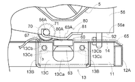
- the load cell support frame 13 is bent upward in the three directions of the right side, the left side, and the rear side of the bottom surface 13A on which the load cell 60 is mounted. That is, it is formed in a box shape including rising piece portions 13B and 13B on the right and left sides of the bottom surface 13A and a rising piece portion 13C on the rear side, with the front and upper sides being open.
- the left and right rising piece portions 13B, 13B of the load cell support frame 13 are welded and fixed to the horizontal frame 11 on the front side and the left and right sides, and are also welded and fixed to the lower surface side of the base plate member 14 so as to be integrated with the body frame 1. It has become.
- a U-shaped cutout 13 ⁇ / b> Ca is formed in the rising piece 13 ⁇ / b> C on the rear side of the load cell support frame 13.
- the notch 13Ca is for allowing dust or the like accumulated on the bottom surface 13A of the load cell support frame 13 formed in a box shape to be swept out during maintenance.
- a holding nut 13Cc is inserted into the rear rising piece portion 13C to sandwich a hanging portion 65A bent downward on the rear end side of the guide plate 65, and a fixing bolt 13Cb is inserted and fixed from the rear side. It is fixed.
- the load cell 60 is mounted on the load cell mounting portion which is the bottom surface 13A of the load cell support frame 13, and the cylindrical main body 61 is fixed to the load cell support frame 13 by a fixing bolt (not shown). It is fixed integrally with.
- a projecting portion 62 is formed in the center on the upper surface side of the main body portion 61, and a cap-shaped detection member is externally fitted to the projecting portion 62 from above, and this detecting member is attached to the detecting portion 63. It is equivalent.
- the pressure receiving surface 63A which is the upper surface of the detection unit 63, and the surface on the back side thereof are formed on flat surfaces parallel to each other.
- the upper surface of the convex part 62 is formed in the spherical shape which the center part swelled slightly, and it is comprised so that it may be easy to receive the load from upper direction in a center position.
- the structure for providing the guide roller 70, the contact part 80, etc. in the upper side detection part 60B is demonstrated. As shown in FIGS. 4, 5, and 7, the pivot shaft 71 of the guide roller 70 is fixedly supported on the front support plate 56 provided on the front wall 5 ⁇ / b> C of the grain tank 5 as follows. Yes.
- a cutout portion 56 ⁇ / b> A that is recessed upward is formed on the lower end edge 56 a side of the front support plate 56.
- the pivot shaft 71 of the guide roller 70 is applied to the far right corner of the notch 56A, and the pivot shaft 71 is held upward from the lower side and the left side.
- the top end on the upper surface side that is bent is applied and fixed by welding.
- the guide roller 70 is pivotally supported on the shaft end side so as to be relatively rotatable with respect to the pivot shaft 71 protruding to the front side of the front support plate 56.
- the guide roller 70 is configured by a ball bearing in which a ball 74 is interposed between an inner race 72 that rotates integrally with the pivot shaft 71 and an outer race 73.
- a cylindrical spacer 75 is interposed between the front support plate 56 and the inner race 72 of the guide roller 70, and is fixed to the front side of the front support plate 56 by welding. Therefore, the range in which the pivotal support action by the front support plate 56 is extended in the length direction of the pivotal support shaft 71.
- the contact portion 80 is configured by a warped plate member 81 having a rectangular shape in plan view, which is applied to the lower end edge 56a of the front support plate 56 from the lower end side in a substantially orthogonal posture and is fixed by welding.
- the sled-like plate member 81 is formed in a bent shape along the lower end edge 56a of the front support plate 56 so that the front and rear end sides in the swinging direction of the grain tank 5 are high and the central portion is low. .
- the lower surface near the center in the swinging direction of the grain tank 5 constitutes a downward contact surface 80 ⁇ / b> A of the contact portion 80.
- the guide roller 70 and the contact portion 80 operate in accordance with the swinging operation around the vertical axis y1 of the grain tank 5, but the swinging of the grain tank 5 from the non-storage position to the storage position side.
- the relative positional relationship among the guide roller 70, the contact part 80, and the detection part 63 during the operation is changed from the following state (1) to the state (2) as shown in FIG.
- the state (1) is a position where the grain tank 5 moves from the non-storage position to the storage position and the guide roller 70 starts to ride on the guide plate 65 on the body frame 1 from now on. Indicates the position.
- the state (2) is a state in which the contact portion 80 is located on the lateral side outside the body frame 1 and the detection unit 63 is not placed on the upper surface thereof.
- the state of (2) is a state in which the guide roller 70 rides on the guide plate 65, and the grain tank 5 has moved to the position immediately before the storage position while rolling on the guide plate 65, and the grain tank 5 is stored. The previous position. At this position, the contact portion 80 reaches a position where a part of the contact portion 80 faces the pressure receiving surface 63A of the detection portion 63, but the center position 80P of the contact portion 80 and the center position of the pressure reception surface 63A of the detection portion 63. 63P is not completely matched. In this state, the contact portion 80 and the detection portion 63 have a slight gap between the opposing surfaces and are separated from each other.
- FIG 3 to 7 show a state where the grain tank 5 further moves and reaches the storage position.
- the guide roller 70 falls into the drop hole 67 on the guide plate 65, and the center position 80P of the contact portion 80 is placed in a state where it matches the center position 63P of the pressure receiving surface 63A of the detection portion 63.
- a lock device 90 for suppressing the shift movement of the grain tank 5 is attached to the front support plate 56 of the grain tank 5 in a state where the grain tank 5 exists at the storage position.
- the locking device 90 is closer to the laterally outer side in the swing movement direction of the grain tank 5 than the portion where the contact portion 80 exists on the front surface of the front support plate 56. Is provided at the location, and is easy to operate from the lateral side of the fuselage.
- the locking device 90 slides in a vertical direction with respect to a crank-shaped mounting bracket 91 welded and fixed to the front surface of the front support plate 56 and a vertical through hole (not shown) formed in the mounting bracket 91.
- a lock pin 92 that can be operated and a coil spring 93 that elastically biases the lock pin 92 downward are provided.
- the lock pin 92 is bent against the urging force of the coil spring 93 by engaging the upper part of the lock pin 92 bent in an L shape with the upper end of the mounting bracket 91. Is held in a state of being pulled upward, that is, in an inoperative state. In this state, the lock pin 92 does not contact the guide plate 65 or the like, and the grain tank 5 is allowed to swing freely.
- the lock pin 92 In a state where the grain tank 5 is in the storage position, the lock pin 92 is locked by rotating the L-shaped bent portion of the lock pin 92 slightly in the horizontal direction and releasing the locking with the upper end of the mounting bracket 91. The pin 92 is pushed downward by the biasing force of the coil spring 93 (see FIG. 3). At this time, if the grain tank 5 exists in the storage position, the lower end portion of the lock pin 92 is formed on a part of the guide plate 65 and the base plate member 14 as shown in FIGS. The locking hole 68 and the locking hole 14 ⁇ / b> C (see FIG. 9) are in positions facing each other. Therefore, in a state where the grain tank 5 exists in the storage position, the lock pin 92 can be inserted and removed in the up-down direction with respect to the locking hole 68 and the locking hole 14C (see FIG. 9).
- a reinforcing support member may be provided separately from the front support plate 56.
- the contact portion 80 is provided with the sled plate member 81 on the front support plate 56 of the grain tank 5, and the sled plate member 81 is disposed behind the front side of the front support plate 56.
- the thing of the structure attached so that it might protrude largely in the side was illustrated, it is not restricted to this.
- it is attached to the lower side of the front support plate 56 so as to protrude by an equal amount on both the front side and the rear side.
- the thing of the structure attached so that it might protrude largely ahead rather than the rear side of the front part support board 56 may be used.
- the body frame 1 is attached to the traveling device 2 via the attitude changing mechanism 200.
- the engine control unit 141 controls the rotational speed of the engine 18 mounted on the machine body frame 1.
- the posture change mechanism 200 changes the posture of the body frame 1 relative to the traveling device 2 by a hydraulic or electric actuator that uses power from the engine 18.
- an engine control unit 141, a device control unit 142, a yield measurement unit 144, a yield control unit 153, a work management unit 154, and a work state determination unit 155 are provided.
- the engine control unit 141 controls the rotational speed of the engine 18.
- the device control unit 142 controls the posture changing mechanism 200 to set the machine body frame 1 in a horizontal posture, and controls the grain unloading device 50 to externally store stored grains from the grain tank 5. And a grain carry-out control unit 422 to be discharged.
- the yield measuring unit 144 measures the yield of the grain stored in the grain tank 5 based on the measurement result of the load cell 60 that is the core component of the weight detection mechanism 6.
- the work state determination unit 155 determines whether the combine is in a work state or a non-work state based on detection signals from the work state detection sensor group 9 and the like, which are generic names of switches, buttons, sensors, and the like that detect the work state. To do.
- the yield control unit 153 gives a high-speed rotation command to the engine control unit 141 in response to a start signal for starting yield measurement by the yield measurement unit 144, which is output through an operation on the start operation tool 9a, and horizontally outputs a horizontal attitude command. This is given to the attitude control unit 421.
- the high speed rotation command is a command for driving the engine 18 at the rated rotation speed.
- the horizontal posture command is a command for operating the posture changing mechanism 200 to place the body frame 1 in a horizontal posture.
- a low-speed rotation command for driving the engine 18 at a no-load rotational speed is given to the engine control unit 141.
- the work management unit 154 sets a work mode for giving a high-speed rotation command to the engine control unit 141 for this control system.
- the yield control unit 153 has a priority control function. This priority control function gives a high-speed rotation command to the engine control unit 141 in preference to the work management unit 154 regardless of the setting mode by the work management unit 154 when an activation signal based on an operation on the activation operation tool 9a is received. It is a function.
- the work management unit 154 performs energy saving automatic control for energy saving operation.
- the engine 18 is rotated at a high speed at the rated rotational speed level during work traveling, and is rotated at a low speed at an idling rotational speed level during non-work traveling.
- an exceptional work situation may occur in which the combine is stopped and exceptional work other than cutting work traveling is performed.
- exceptional work include a yield measurement work for measuring the amount of grain stored in the grain tank 5, or a confirmation work and setting work for various functions. Even in such exceptional work, it is usually necessary to operate an operating device for posture change work for shifting the body frame 1 to a specific posture such as a horizontal posture.
- the yield control unit 153 can give a high-speed rotation command to the engine control unit 141 in preference to the work management unit 154 when receiving a start signal based on an operation on the start operation tool 9a. That is, the yield control unit 153 temporarily stops the function of the work management unit 154 based on the activation signal based on the operation on the activation operation tool 9a.
- the accelerator operating tool 9b is used to return the engine speed setting to the driver. That is, by operating the accelerator operation tool 9b, a desired rotation command for driving the engine 18 at a desired engine speed based on the operation amount is given to the engine control unit 141.
- the energy saving automatic control by the work management unit 154 is temporarily stopped through the operation of the activation operation tool 9a, and the yield control unit 153 can give a rotation command to the engine control unit 141 in preference to the work management unit 154.
- Such priority control of the yield control unit 153 with respect to the work management unit 154 is canceled when the exceptional work causing the priority control, for example, yield measurement is completed, and the energy saving automatic control by the work management unit 154 is restored again. To do. That is, when the yield measurement by the start signal is completed when the yield control unit 153 prioritizes the work management unit 154, the priority of the yield control unit 153 with respect to the work management unit 154 is canceled.
- FIG. 10 shows a grain carry-out device 50 that discharges the grain stored in the grain tank 5 to the outside, and a grain carry-out control unit 422 that controls the grain carry-out device 50.
- Yield measurement is performed prior to the grain unloading operation using the grain unloading device 50. For this reason, it is convenient if the starting operation tool 9a is the starting operation tool 9a for the grain carrying-out work.
- the basic state of the grain unloading device 50 is created in response to the activation signal based on the operation of the activation operation tool 9a. In this basic state, power cut-off to the harvesting work device, return of the harvesting work device to the non-working position, fixation of the movable device constituting the grain unloading device 50, and the like are executed.
- the yield control unit 153 gives a basic state command to the grain carry-out control unit 422, and the basic state transition control in which the grain carry-out control unit 422 gives a basic state control signal to the grain carry-out device 50 is used for yield measurement. Done in advance.
- FIG. 11 is a side view of the combine
- FIG. 12 is a plan view.
- This combine is a self-removable combine, and a machine body frame 1 constituting a traveling machine body 10 is supported on the ground by a pair of crawler-type left and right traveling devices 2.
- a cutting unit 8 that cuts the harvested planted rice cake and conveys the harvested rice cake toward the rear of the aircraft is arranged at the front of the aircraft, and behind that, the control unit 300 without a cabin, and further, the harvested rice cake Threshing device 4 for threshing / sorting, grain tank 5 for storing the grain selected and recovered by threshing device 4, grain unloading device 50 for discharging the grain from grain tank 5, and waste for processing the waste straw A straw processing device 7 and the like are arranged.
- An engine 18 is disposed below the control unit 300.
- the cutting part 8 is connected to the body frame 1 so as to be movable up and down about the body horizontal axis Px.
- the mowing unit 8 is swung up and down with respect to the body frame 1 by the elevating cylinder 130.
- the cutting unit 8 is in a working state in which the weeding tools arranged in the lateral direction of the traveling machine body at the front end of the cutting unit 8 are lowered near the farm scene, and the non-working in which the weeding tool is elevated from the farm scene. Go up and down to the state.
- the threshing device 4 threshs the tip side of the harvested corn straw conveyed from the reaping unit 8, and cerealized into grains by a sorting action (not shown) provided in the threshing device 4. And separated into dust such as straw scraps, etc., and a single grain is transported to the grain tank 5 as a harvest.
- the waste straw after the threshing process is shredded by the waste straw processing apparatus 7.
- a grain transport mechanism for sending the grain from the threshing device 4 to the grain tank 5 is arranged.
- This grain conveying device is composed of a first thing recovery screw 40 provided at the bottom of the threshing device 4 and a screw conveyor type cerealing device 41.
- the grain that has been laterally fed by the first thing collecting screw 40 is conveyed upward by the cerealing device 41 and fed into the grain tank 5 through the inlet formed in the upper part of the grain tank 5.
- illustration is abbreviate
- the operation unit 300 includes an activation operation tool 9 a, an accelerator operation tool 9 b, a simple automatic control button 9 c, and a control lever 35.
- the control lever 35 When the control lever 35 is operated in the front-rear direction, the cutting unit 8 is moved up and down, and when the control lever 35 is operated in the left-right direction, the crawler type traveling device 2 in the operation direction decelerates or stops and the traveling body 10 is moved. Turn left or right.
- the activation operation tool 9a is used to start measuring the yield of the grain stored in the grain tank 5.
- the accelerator operation tool 9b is used to artificially adjust the rotational speed of the engine 18.
- the simple automatic control button 9c is used to execute at least partially an automatic work operation automatically performed by the machine in place of the driver's judgment or an energy saving control operation for supplying only necessary power.
- the simple automatic control button 9c summarizes the ON setting of the threshing clutch 4a and the ON setting of the cutting clutch 8a in the harvesting operation, and the engine speed automatic control for rotating the engine 18 at a low speed when not working. Used as a button to execute.
- the engine speed is maintained at the high speed that is the rated speed when the combine is in the working state, and the engine speed is maintained at the low speed that is the idling speed in the non-working state. Is done.
- one of the left and right track frames 2 a is moved up and down between the body frame 1 and the track frame 2 a of the crawler type traveling device 2.
- Attitude changing mechanism having a rolling function for horizontally moving the vehicle body frame 1 with respect to the left and right inclination of the vehicle and a pitching function for horizontally moving the vehicle body frame 1 with respect to the front and rear inclination of the vehicle body by raising or lowering either the front or back of the track frame 2a. 200 is provided.
- a support metal 201 is provided below the front side of the machine body frame 1, and a shaft portion 202 in the left-right direction of the machine body is provided on the support metal 201 to be rotatable.
- the base portion of the front operation arm 203 is fixed to the inner end portion of the shaft portion 202, and the end portion opposite to the base portion of the front operation arm 203 is positioned on the rear side of the machine body.
- a base portion of the front elevating arm 204 is fixed to an outer end portion of the shaft portion 202, and the other end of the front elevating arm 204 is connected to the track frame 2 a via the shaft 205.
- a support metal 206 is provided below the rear side of the machine body frame 1, and a shaft part 207 in the left-right direction of the machine body is rotatably provided on the support metal 206.
- the base portion of the rear operation arm 208 is fixed to the inner end portion of the shaft portion 207, and the end portion opposite to the base portion of the rear operation arm 208 is positioned on the rear side of the machine body.
- One end of the rear lifting first arm 209 is fixed to the outer end of the shaft portion 207, and the other end of the rear lifting first arm 209 is attached to the shaft 210.
- a base of a rear raising / lowering second arm 211 is swingably attached to the shaft 210, and the other end of the rear raising / lowering second arm 211 is connected to the track frame 2 a via a shaft 212.
- a piston rod 214 of a single-acting hydraulic cylinder 213 for rolling is attached to the end of the front operation arm 203.
- a hydraulic cylinder 213 is arranged in the vertical direction across the front operation arm 203 and the body frame 1.
- a piston rod 217 of a single acting hydraulic cylinder 216 for rolling and pitching is pivotally attached to an end of the rear operation arm 208.
- a hydraulic cylinder 216 is arranged in the vertical direction across the rear operation arm 208 and the body frame 1.
- Two hydraulic cylinders 213 and 216 are arranged in front of and behind the left and right track frames 2a. Each of the hydraulic cylinders 213 and 216 is independently operated and the amount of operation is controlled so that the airframe is pitched and rolled.
- the rolling hydraulic cylinder 213 and the rolling / pitching hydraulic cylinder 216 have the same cross-sectional area, and when the aircraft is rolled, the right or left hydraulic cylinder 213, 216 is expanded and contracted by the same amount, and the aircraft is pitched. At that time, only the left and right hydraulic cylinders 216 are expanded and contracted.
- both the front operation arm 203 and the front lifting arm 204 are extended toward the rear of the machine body with respect to the shaft part 202, and from the shaft part 202 of the front operation arm 203 to the rear of the machine body. Is set to be the same as or shorter than the length in the rear direction of the machine body from the shaft portion 202 of the front lifting arm 204.
- a hydraulic cylinder 213 having a piston rod 214 protruding and retracting downward is disposed in the vertical direction at the end of the front operation arm 203.
- the rear operation arm 208, the rear lifting first arm 209, and the rear lifting second arm 211 are all extended toward the rear of the machine body with respect to the shaft portion 207.
- the length in the rearward direction of the body from 207 is set to be the same as or shorter than the length in the rearward direction of the body from the shaft portion 207 of the rear lifting first arm 209 and the rear lifting second arm 211.
- a hydraulic cylinder 216 having a piston rod 217 extending and retracting downward is disposed in the vertical direction at the end of the rear operation arm 208.
- the horizontal posture of the traveling machine body 10 can be created regardless of the state of the ground surface, and the ground posture is the lowest in ground height.
- a lower limit posture can be created.
- the grain unloading device 50 includes a bottom screw 51 provided at the bottom of the grain tank 5, and a vertical feed screw conveyor 52 provided on the rear side of the machine body of the grain tank 5. And a transverse feed screw conveyor 53 extending above the threshing device 4.
- the grain stored in the grain tank 5 is sent from the bottom screw 51 to the transverse feed screw conveyor 53 via the longitudinal feed screw conveyor 52 and is discharged to the outside from the discharge port 53A provided at the tip of the transverse feed screw conveyor 53. Discharged.
- the vertical feed screw conveyor 52 is configured to be rotatable around the vertical axis y1 by the operation of the electric motor 54, and the horizontal feed screw conveyor 53 swings up and down around the horizontal axis X1 at the base end by the hydraulic cylinder 55. It is configured to be operable. Thereby, the discharge port 53A of the lateral feed screw conveyor 53 can be positioned at a position where the grain can be discharged to a transport truck or the like outside the machine.
- the position at which the transverse feed screw conveyor 53 is substantially horizontal and the entire transverse feed screw conveyor 53 is within the outline of the harvester in plan view is the home position of the transverse feed conveyor 53 (home position of the grain unloading device 50). In this home position, the transverse screw conveyor 53 is firmly held and fixed from below by a holding device 57.
- the bottom of the grain tank 5 is inclined so that the left bottom wall and the right bottom wall create a wedge shape facing downward, and a bottom screw 51 is disposed in the tip region.
- the left side wall 5A and the right side wall 5B connected to the upper ends of the left bottom wall and the right bottom wall are almost upright. With such a structure of the grain tank 5, the grain charged into the grain tank 5 flows down toward the bottom screw 51.
- a turning support portion 15 as a cylindrical swing support shaft is provided at the rear end portion of the grain tank 5.
- the swing axis of the turning support 15 is a vertical axis X1 that coincides with the vertical axis y1.
- the grain tank 5 is capable of horizontal swinging around the vertical axis X1 as indicated by the dotted line in FIG. That is, the grain tank 5 has a working position where the grain can be received from the cerealing device 41, and protrudes laterally outward, the front side is separated from the threshing device 4, the rear of the control unit 300 and the threshing device 4. The position can be changed over the maintenance position where the right side of the door is opened.
- FIG. 16 is a perspective view of the vicinity of the load cell 60 during the transition of the grain tank 5 from the maintenance position to the work position.
- FIG. 17 is a cross-sectional view of the vicinity of the load cell 60 when the grain tank 5 returns to the work position. At this position, the load cell 60 receives the weight of the grain tank 5 and outputs the weight as a measurement result.
- the load cell 60 is mounted on the body frame 1, and a receiving guide piece 621 that guides the lower part of the grain tank 5 toward the weight detection unit 602 of the load cell 60 is disposed so as to cover the load cell 60.
- the receiving guide piece 621 receives and supports the lower end of the grain tank 5 as the grain tank 5 rotates from the maintenance position toward the work position, while the weight detecting unit 602 of the load cell 60 supports the grain tank 5.
- the weight of the grain tank 5 is measured by the load cell 60 there.
- the receiving guide piece 621 has an inclined surface so that the grain tank 5 is guided while being lifted as the grain tank 5 rotates from the maintenance position to the work position.
- a flat surface further extends from the inclined surface, and a tip portion located at the tip is an inclined surface inclined downward.
- the receiving guide piece 621 has a skirt portion, and is pivotally supported by a pivot pin so as to be swingable around the body longitudinal axis P4 along the body longitudinal direction with respect to the bracket 110a fixed to the body frame 1.
- a cap member 601 formed in a downward cylindrical shape is placed on the weight detection unit 602 of the load cell 60 from above. Therefore, at the work position of the grain tank 5, the upper surface of the cap member 601 contacts the lower surface of the receiving guide piece 621, and the lower surface of the cap member 601 contacts the pressure receiving surface 63 ⁇ / b> A of the weight detection unit 602 from above. That is, the load on the front side of the grain tank 5 is received by the load cell 60 via the receiving guide piece 621 and the cap member 601.
- an angle-shaped support base 624 is attached to the lower part of the grain tank 5, and a roller 622 is rotatably supported on a vertical wall of the support base 624 via a horizontal support shaft 623. .
- the lower end of the roller 622 is positioned below the lower surface of the horizontal wall of the support base 624 so that the roller 622 comes into contact with the receiving guide piece 621. For this reason, when the roller 622 is guided by the receiving guide piece 621, the horizontal wall of the support base 624 does not contact the receiving guide piece 621, and the roller 622 is detached from the tip end portion of the receiving guide piece 621. For the first time, the horizontal wall of the support base 624 makes surface contact with the flat surface of the receiving guide piece 621.
- the support base 624 is attached to the grain tank 5 so that the height can be adjusted via an adjustment mechanism.
- the adjustment mechanism includes, for example, a fixing bolt that fixes the support base 624 to the grain tank 5 using a long hole, and an adjustment bolt that presses the upper end against the lower surface of the grain tank 5. It can be easily configured by a combination.
- an auxiliary guide body 625 is provided in the lower part of the grain tank 5 adjacent to the support base 624.
- the auxiliary guide body 625 is a sled member attached to the front surface of the holding device 58 and includes an auxiliary roller 626.
- the auxiliary roller 626 rolls along the inclined surface of the inclined table 111 provided on the machine body frame 1.
- the auxiliary guide body 625 and the inclined base 111 are designed so that the auxiliary roller 626 also has a mutual positional relationship away from the inclined base 111 when the roller 622 passes through the receiving guide piece 621.
- the roller 622 and the auxiliary roller 626 are in a suspended state, and the lower surface of the horizontal wall of the support base 624 and the flat surface of the receiving guide piece 621 are in surface contact.
- the weight of the grain tank 5 and, as a result, the weight (yield) of the grain stored in the grain tank 5 are measured by the load cell 60.
- FIG. 18 is a functional block diagram showing functional elements related to yield measurement during simple automatic control in the control system.
- the basic function described with reference to FIG. 10 is used for the control function and control flow in the combine of this embodiment.
- a first module 140 that directly exchanges signals with an operating device of a combine
- a second module 150 that exchanges control data with the first module 140. It is divided into.
- the first module 140 and the second module 150 are interconnected by a signal transmission line, an in-vehicle LAN, and other data transmission lines.
- the first module 140 includes an engine control unit 141, a device control unit 142, an input signal processing unit 143, and a yield measurement unit 144.
- the engine control unit 141 controls the rotational speed of the engine 18.
- the device control unit 142 controls various operating devices of the combine.
- the horizontal posture control unit 421 of the device control unit 142 has a function of controlling the posture changing mechanism 200 to bring the machine body frame 1 into a horizontal posture
- the grain carry-out control unit 422 uses the grain carry-out device 50. It has a function of controlling and discharging stored grains from the grain tank 5 to the outside.
- the input signal processing unit 143 includes sensors, switches, and the like that detect signals from human operation devices such as the start operation tool 9a, the accelerator operation tool 9b, the simple automatic control button 9c, and the control lever 35, and the state of the equipment constituting the combine.
- a signal from the work state detection sensor group 9 is input and transferred to each functional unit of the control unit 100.
- the working state detection sensor group 9 includes, for example, a speed detector that detects the stop of the combine, a detector that detects a shift to the horizontal position that is the home position of the horizontal control mechanism of the body mounted on the combine, and a cutting unit 8 and a detector that detects the state of a clutch that controls the transmission of power to the threshing device 4, and the home position of the grain unloading device 50 that is held and fixed by the holding device 57 of the lateral feed screw conveyor 53 (grain unloading)
- a detector for detecting the storage position of the device 50 is included.
- the yield measuring unit 144 measures the yield of the grain stored in the grain tank 5 based on the measurement result of the load cell 60. The grain yield is obtained by subtracting the weight of the grain tank 5 from the weight determined from the measurement result of the load cell 60.
- the second module 150 includes a travel device control unit 151, a work device control unit 152, a yield control unit 153, a work management unit 154, and a work state determination unit 155.
- the travel device control unit 151 generates a control command for performing drive control on the travel device 2 based on the operation command through the control device received via the input signal processing unit 143.
- the control command generated by the travel device control unit 151 is sent to an operation device such as a transmission mechanism through the device control unit 142.
- the work device control unit 152 performs drive control on the reaping unit 8, the threshing device 4, and its peripheral devices based on the operation command from the work operation device and the detection signal from the work state detection sensor group 9.
- the control command is generated.
- the control command generated by the work device control unit 152 is sent to an operation device such as a transmission mechanism through the device control unit 142.
- an operation device such as a transmission mechanism through the device control unit 142.
- the horizontal posture control unit 421 and the grain carry-out control unit 422 are separately described above, but the horizontal posture control unit 421 and the grain carry-out control unit 422 are incorporated in the work device control unit 152. it can.
- the explanation using FIG. 10 is diverted for each function of the yield control unit 153, the work management unit 154, and the work state determination unit 155.
- the work state determination unit 155 has a function of determining whether the combine is in a work state or a non-work state based on a detection signal from the work state detection sensor group 9 or the like.
- the work management unit 154 coordinates the ON setting of the threshing clutch 4a and the ON setting of the mowing clutch 8a in the reaping work, and further, the engine speed automatic control for rotating the engine 18 at a low speed when not working.
- Manage simple automatic control while executing. Simple automatic control under the management of the work management unit 154 is activated by a simple automatic control button 9c.
- the work management unit 154 sets a work mode in which a high-speed rotation command is given to the engine control unit 141 for the control unit 100 when the work state determination unit 155 determines the work state. Further, the work management unit 154 sets a non-working mode in which a low-speed rotation command is given to the engine control unit 141 to the control unit 100 when the work state determination unit 155 determines the non-working mode.
- the yield control unit 153 has a function of managing the yield measurement by the yield measurement unit 144, and the yield measurement unit 144 uses the measurement value / yield conversion table used when deriving the yield from the measurement value that is the measurement result of the load cell 60. Set up. Further, the yield control unit 153 uses the activation signal as a trigger to activate the yield measurement by the activation operation tool 9a, and determines whether the control unit 100 is in the simple automatic control state or the mode ( Various commands are generated and given to each functional unit in consideration of the working mode or the non-working mode.
- the work management unit 154 gives a low-speed rotation command to the engine control unit 141 to save energy, and the work mode is set. Gives a high-speed rotation command for effective harvesting work.
- the yield control unit 153 performs the function of the simple automatic control by the work management unit 154. Once stopped, a high speed rotation command is forcibly given to the engine control unit 141.
- the yield control unit 153 gives a horizontal posture command to the horizontal posture control unit 421 to set the body frame 1 in a horizontal posture.
- the posture changing mechanism 200 can perform a posture changing operation based on sufficient power of the engine 18.
- the yield control unit 153 gives a basic state command to the grain carry-out control unit 422, and shifts to the home position state if the grain carry-out device 50 is not in the home position state suitable for yield measurement.
- the yield control unit 153 gives a yield measurement command to the yield measurement unit 144.
- the yield measuring unit 144 performs yield measurement, obtains a measurement value from the load cell 60, and calculates the yield.
- the yield control unit 153 sends the grain carrying-out control unit 422 to the substantial grain discharging work. Give the start command.
- the control unit 100 records the yield calculated by the yield measuring unit 144 in the memory. At that time, the field name, the type of harvest, and the like are also recorded as the attribute values of the yield.
- control unit 100 shown in FIGS. 10 and 18 is an example, and the integration of the functional units and the division of the functional units are arbitrary. Any configuration is possible as long as the control function of the present invention is realized, and these functions can be realized by hardware and / or software.
- Artificial operation devices such as the start operation tool 9a, the accelerator operation tool 9b, the simple automatic control button 9c, and the control lever 35 may be realized by a mechanical type or by a software operation body arranged on the touch panel. Also good. Further, these artificial operation devices can be realized in any combination.
- the present invention is applicable not only to a self-removing combine but also to an ordinary combine, as well as to a corn harvester and other crop harvesters other than a combine.
Priority Applications (4)
| Application Number | Priority Date | Filing Date | Title |
|---|---|---|---|
| KR1020177011148A KR102521831B1 (ko) | 2015-03-18 | 2015-09-25 | 콤바인 |
| EP15885544.5A EP3272204B1 (en) | 2015-03-18 | 2015-09-25 | Combine harvester |
| US15/520,220 US10143133B2 (en) | 2015-03-18 | 2015-09-25 | Combine |
| CN201580060340.6A CN107072150B (zh) | 2015-03-18 | 2015-09-25 | 联合收割机 |
Applications Claiming Priority (4)
| Application Number | Priority Date | Filing Date | Title |
|---|---|---|---|
| JP2015055135A JP6355579B2 (ja) | 2015-03-18 | 2015-03-18 | コンバイン |
| JP2015-055135 | 2015-03-18 | ||
| JP2015-067058 | 2015-03-27 | ||
| JP2015067058A JP6355584B2 (ja) | 2015-03-27 | 2015-03-27 | コンバイン |
Publications (1)
| Publication Number | Publication Date |
|---|---|
| WO2016147452A1 true WO2016147452A1 (ja) | 2016-09-22 |
Family
ID=56918679
Family Applications (1)
| Application Number | Title | Priority Date | Filing Date |
|---|---|---|---|
| PCT/JP2015/077007 WO2016147452A1 (ja) | 2015-03-18 | 2015-09-25 | コンバイン |
Country Status (5)
| Country | Link |
|---|---|
| US (1) | US10143133B2 (zh) |
| EP (1) | EP3272204B1 (zh) |
| KR (1) | KR102521831B1 (zh) |
| CN (1) | CN107072150B (zh) |
| WO (1) | WO2016147452A1 (zh) |
Families Citing this family (3)
| Publication number | Priority date | Publication date | Assignee | Title |
|---|---|---|---|---|
| JP6697964B2 (ja) * | 2016-06-27 | 2020-05-27 | 株式会社クボタ | コンバイン |
| DE102017200336A1 (de) * | 2017-01-11 | 2018-07-12 | Deere & Company | Modellbasierte prädiktive Geschwindigkeitskontrolle einer Erntemaschine |
| WO2019198707A1 (ja) * | 2018-04-12 | 2019-10-17 | 株式会社クボタ | 収穫機 |
Citations (3)
| Publication number | Priority date | Publication date | Assignee | Title |
|---|---|---|---|---|
| JP2013118857A (ja) * | 2011-12-08 | 2013-06-17 | Kubota Corp | コンバイン |
| JP2014064533A (ja) * | 2012-09-26 | 2014-04-17 | Kubota Corp | コンバイン |
| JP2014187945A (ja) * | 2013-03-27 | 2014-10-06 | Kubota Corp | コンバイン |
Family Cites Families (15)
| Publication number | Priority date | Publication date | Assignee | Title |
|---|---|---|---|---|
| JP3710910B2 (ja) | 1997-02-20 | 2005-10-26 | ヤンマー農機株式会社 | コンバイン |
| JPH11151022A (ja) * | 1997-11-19 | 1999-06-08 | Yanmar Agricult Equip Co Ltd | 移動農機の車速制御装置 |
| JP2005087155A (ja) * | 2003-09-19 | 2005-04-07 | Yanmar Agricult Equip Co Ltd | コンバイン |
| JP2005124423A (ja) * | 2003-10-21 | 2005-05-19 | Yanmar Co Ltd | コンバイン |
| CN100425113C (zh) * | 2003-12-05 | 2008-10-15 | 中国农业机械化科学研究院 | 一种联合收割机粮食产量流量监视方法及装置 |
| JP2007295932A (ja) * | 2007-06-20 | 2007-11-15 | Yanmar Agricult Equip Co Ltd | コンバイン |
| JP5508619B2 (ja) * | 2009-08-12 | 2014-06-04 | ヤンマー株式会社 | コンバイン |
| US9043096B2 (en) * | 2011-03-31 | 2015-05-26 | Ag Leader Technology | Combine bin level monitoring system |
| KR102022594B1 (ko) * | 2012-09-26 | 2019-11-20 | 가부시끼 가이샤 구보다 | 콤바인 |
| US9187259B2 (en) * | 2013-03-15 | 2015-11-17 | Unverferth Manufacturing Company, Inc. | Method for controlling an unload operation on a mobile farm implement |
| US9372109B2 (en) * | 2013-03-15 | 2016-06-21 | Raven Industires, Inc. | Harvester elevator in-flow weight sensor and methods for the same |
| US9272853B2 (en) * | 2013-03-15 | 2016-03-01 | Unverferth Manufacturing Company, Inc. | Weight-based chute control for a farm implement |
| EP2979537B1 (en) * | 2013-03-27 | 2019-08-28 | Kubota Corporation | Combine |
| JP5980162B2 (ja) * | 2013-04-26 | 2016-08-31 | 株式会社クボタ | コンバイン |
| US9872433B2 (en) * | 2015-05-14 | 2018-01-23 | Raven Industries, Inc. | System and method for adjusting harvest characteristics |
-
2015
- 2015-09-25 US US15/520,220 patent/US10143133B2/en active Active
- 2015-09-25 CN CN201580060340.6A patent/CN107072150B/zh active Active
- 2015-09-25 WO PCT/JP2015/077007 patent/WO2016147452A1/ja active Application Filing
- 2015-09-25 KR KR1020177011148A patent/KR102521831B1/ko active IP Right Grant
- 2015-09-25 EP EP15885544.5A patent/EP3272204B1/en active Active
Patent Citations (3)
| Publication number | Priority date | Publication date | Assignee | Title |
|---|---|---|---|---|
| JP2013118857A (ja) * | 2011-12-08 | 2013-06-17 | Kubota Corp | コンバイン |
| JP2014064533A (ja) * | 2012-09-26 | 2014-04-17 | Kubota Corp | コンバイン |
| JP2014187945A (ja) * | 2013-03-27 | 2014-10-06 | Kubota Corp | コンバイン |
Non-Patent Citations (1)
| Title |
|---|
| See also references of EP3272204A4 * |
Also Published As
| Publication number | Publication date |
|---|---|
| CN107072150B (zh) | 2020-10-27 |
| KR20170126848A (ko) | 2017-11-20 |
| KR102521831B1 (ko) | 2023-04-17 |
| EP3272204A1 (en) | 2018-01-24 |
| US10143133B2 (en) | 2018-12-04 |
| CN107072150A (zh) | 2017-08-18 |
| EP3272204A4 (en) | 2019-02-20 |
| EP3272204B1 (en) | 2021-06-30 |
| US20170311544A1 (en) | 2017-11-02 |
Similar Documents
| Publication | Publication Date | Title |
|---|---|---|
| KR102112694B1 (ko) | 콤바인 | |
| JP2011036193A (ja) | コンバイン | |
| WO2016147452A1 (ja) | コンバイン | |
| JP5531709B2 (ja) | コンバインの刈り高さ検出装置 | |
| JP4689653B2 (ja) | コンバイン | |
| JP6355579B2 (ja) | コンバイン | |
| JP5756070B2 (ja) | コンバイン | |
| KR101800112B1 (ko) | 보통형 콤바인의 예취부 제어장치 | |
| JP6355584B2 (ja) | コンバイン | |
| KR101324008B1 (ko) | 콤바인 | |
| JPH0249513A (ja) | コンバインの脱穀装置 | |
| JP4261725B2 (ja) | コンバインの排出オーガ | |
| JP4551232B2 (ja) | コンバイン | |
| JP4840281B2 (ja) | コンバイン | |
| KR20200103469A (ko) | 오거 동작에 연계한 콤바인의 엔진 rpm 제어 장치 및 방법 | |
| JP6373147B2 (ja) | コンバイン | |
| JP2003009644A (ja) | 穀粒排出装置 | |
| JPH0713473Y2 (ja) | 収穫機における刈取前処理装置 | |
| JP2598336Y2 (ja) | 収穫機 | |
| JP2009142192A (ja) | コンバイン | |
| JP2017099298A (ja) | コンバイン | |
| JP2000139184A (ja) | コンバイン | |
| JP2010172265A (ja) | コンバイン | |
| JP3401643B2 (ja) | コンバイン | |
| JP3230087B2 (ja) | コンバイン |
Legal Events
| Date | Code | Title | Description |
|---|---|---|---|
| 121 | Ep: the epo has been informed by wipo that ep was designated in this application |
Ref document number: 15885544 Country of ref document: EP Kind code of ref document: A1 |
|
| WWE | Wipo information: entry into national phase |
Ref document number: 15520220 Country of ref document: US |
|
| REEP | Request for entry into the european phase |
Ref document number: 2015885544 Country of ref document: EP |
|
| ENP | Entry into the national phase |
Ref document number: 20177011148 Country of ref document: KR Kind code of ref document: A |
|
| NENP | Non-entry into the national phase |
Ref country code: DE |