WO2016143773A1 - 復水器 - Google Patents
復水器 Download PDFInfo
- Publication number
- WO2016143773A1 WO2016143773A1 PCT/JP2016/057094 JP2016057094W WO2016143773A1 WO 2016143773 A1 WO2016143773 A1 WO 2016143773A1 JP 2016057094 W JP2016057094 W JP 2016057094W WO 2016143773 A1 WO2016143773 A1 WO 2016143773A1
- Authority
- WO
- WIPO (PCT)
- Prior art keywords
- water chamber
- inlet
- outlet
- condenser
- outlet water
- Prior art date
- Legal status (The legal status is an assumption and is not a legal conclusion. Google has not performed a legal analysis and makes no representation as to the accuracy of the status listed.)
- Ceased
Links
Images







Classifications
-
- F—MECHANICAL ENGINEERING; LIGHTING; HEATING; WEAPONS; BLASTING
- F28—HEAT EXCHANGE IN GENERAL
- F28F—DETAILS OF HEAT-EXCHANGE AND HEAT-TRANSFER APPARATUS, OF GENERAL APPLICATION
- F28F9/00—Casings; Header boxes; Auxiliary supports for elements; Auxiliary members within casings
- F28F9/007—Auxiliary supports for elements
-
- F—MECHANICAL ENGINEERING; LIGHTING; HEATING; WEAPONS; BLASTING
- F01—MACHINES OR ENGINES IN GENERAL; ENGINE PLANTS IN GENERAL; STEAM ENGINES
- F01D—NON-POSITIVE DISPLACEMENT MACHINES OR ENGINES, e.g. STEAM TURBINES
- F01D25/00—Component parts, details, or accessories, not provided for in, or of interest apart from, other groups
- F01D25/04—Antivibration arrangements
-
- F—MECHANICAL ENGINEERING; LIGHTING; HEATING; WEAPONS; BLASTING
- F01—MACHINES OR ENGINES IN GENERAL; ENGINE PLANTS IN GENERAL; STEAM ENGINES
- F01D—NON-POSITIVE DISPLACEMENT MACHINES OR ENGINES, e.g. STEAM TURBINES
- F01D25/00—Component parts, details, or accessories, not provided for in, or of interest apart from, other groups
- F01D25/24—Casings; Casing parts, e.g. diaphragms, casing fastenings
-
- F—MECHANICAL ENGINEERING; LIGHTING; HEATING; WEAPONS; BLASTING
- F01—MACHINES OR ENGINES IN GENERAL; ENGINE PLANTS IN GENERAL; STEAM ENGINES
- F01D—NON-POSITIVE DISPLACEMENT MACHINES OR ENGINES, e.g. STEAM TURBINES
- F01D25/00—Component parts, details, or accessories, not provided for in, or of interest apart from, other groups
- F01D25/28—Supporting or mounting arrangements, e.g. for turbine casing
-
- F—MECHANICAL ENGINEERING; LIGHTING; HEATING; WEAPONS; BLASTING
- F16—ENGINEERING ELEMENTS AND UNITS; GENERAL MEASURES FOR PRODUCING AND MAINTAINING EFFECTIVE FUNCTIONING OF MACHINES OR INSTALLATIONS; THERMAL INSULATION IN GENERAL
- F16F—SPRINGS; SHOCK-ABSORBERS; MEANS FOR DAMPING VIBRATION
- F16F15/00—Suppression of vibrations in systems; Means or arrangements for avoiding or reducing out-of-balance forces, e.g. due to motion
- F16F15/02—Suppression of vibrations of non-rotating, e.g. reciprocating systems; Suppression of vibrations of rotating systems by use of members not moving with the rotating systems
- F16F15/023—Suppression of vibrations of non-rotating, e.g. reciprocating systems; Suppression of vibrations of rotating systems by use of members not moving with the rotating systems using fluid means
-
- F—MECHANICAL ENGINEERING; LIGHTING; HEATING; WEAPONS; BLASTING
- F16—ENGINEERING ELEMENTS AND UNITS; GENERAL MEASURES FOR PRODUCING AND MAINTAINING EFFECTIVE FUNCTIONING OF MACHINES OR INSTALLATIONS; THERMAL INSULATION IN GENERAL
- F16F—SPRINGS; SHOCK-ABSORBERS; MEANS FOR DAMPING VIBRATION
- F16F15/00—Suppression of vibrations in systems; Means or arrangements for avoiding or reducing out-of-balance forces, e.g. due to motion
- F16F15/02—Suppression of vibrations of non-rotating, e.g. reciprocating systems; Suppression of vibrations of rotating systems by use of members not moving with the rotating systems
- F16F15/04—Suppression of vibrations of non-rotating, e.g. reciprocating systems; Suppression of vibrations of rotating systems by use of members not moving with the rotating systems using elastic means
- F16F15/06—Suppression of vibrations of non-rotating, e.g. reciprocating systems; Suppression of vibrations of rotating systems by use of members not moving with the rotating systems using elastic means with metal springs
-
- F—MECHANICAL ENGINEERING; LIGHTING; HEATING; WEAPONS; BLASTING
- F16—ENGINEERING ELEMENTS AND UNITS; GENERAL MEASURES FOR PRODUCING AND MAINTAINING EFFECTIVE FUNCTIONING OF MACHINES OR INSTALLATIONS; THERMAL INSULATION IN GENERAL
- F16F—SPRINGS; SHOCK-ABSORBERS; MEANS FOR DAMPING VIBRATION
- F16F15/00—Suppression of vibrations in systems; Means or arrangements for avoiding or reducing out-of-balance forces, e.g. due to motion
- F16F15/02—Suppression of vibrations of non-rotating, e.g. reciprocating systems; Suppression of vibrations of rotating systems by use of members not moving with the rotating systems
- F16F15/04—Suppression of vibrations of non-rotating, e.g. reciprocating systems; Suppression of vibrations of rotating systems by use of members not moving with the rotating systems using elastic means
- F16F15/06—Suppression of vibrations of non-rotating, e.g. reciprocating systems; Suppression of vibrations of rotating systems by use of members not moving with the rotating systems using elastic means with metal springs
- F16F15/067—Suppression of vibrations of non-rotating, e.g. reciprocating systems; Suppression of vibrations of rotating systems by use of members not moving with the rotating systems using elastic means with metal springs using only wound springs
-
- F—MECHANICAL ENGINEERING; LIGHTING; HEATING; WEAPONS; BLASTING
- F25—REFRIGERATION OR COOLING; COMBINED HEATING AND REFRIGERATION SYSTEMS; HEAT PUMP SYSTEMS; MANUFACTURE OR STORAGE OF ICE; LIQUEFACTION SOLIDIFICATION OF GASES
- F25B—REFRIGERATION MACHINES, PLANTS OR SYSTEMS; COMBINED HEATING AND REFRIGERATION SYSTEMS; HEAT PUMP SYSTEMS
- F25B39/00—Evaporators; Condensers
-
- F—MECHANICAL ENGINEERING; LIGHTING; HEATING; WEAPONS; BLASTING
- F28—HEAT EXCHANGE IN GENERAL
- F28B—STEAM OR VAPOUR CONDENSERS
- F28B1/00—Condensers in which the steam or vapour is separate from the cooling medium by walls, e.g. surface condenser
- F28B1/02—Condensers in which the steam or vapour is separate from the cooling medium by walls, e.g. surface condenser using water or other liquid as the cooling medium
-
- F—MECHANICAL ENGINEERING; LIGHTING; HEATING; WEAPONS; BLASTING
- F28—HEAT EXCHANGE IN GENERAL
- F28D—HEAT-EXCHANGE APPARATUS, NOT PROVIDED FOR IN ANOTHER SUBCLASS, IN WHICH THE HEAT-EXCHANGE MEDIA DO NOT COME INTO DIRECT CONTACT
- F28D7/00—Heat-exchange apparatus having stationary tubular conduit assemblies for both heat-exchange media, the media being in contact with different sides of a conduit wall
- F28D7/16—Heat-exchange apparatus having stationary tubular conduit assemblies for both heat-exchange media, the media being in contact with different sides of a conduit wall the conduits being arranged in parallel spaced relation
- F28D7/163—Heat-exchange apparatus having stationary tubular conduit assemblies for both heat-exchange media, the media being in contact with different sides of a conduit wall the conduits being arranged in parallel spaced relation with conduit assemblies having a particular shape, e.g. square or annular; with assemblies of conduits having different geometrical features; with multiple groups of conduits connected in series or parallel and arranged inside common casing
-
- F—MECHANICAL ENGINEERING; LIGHTING; HEATING; WEAPONS; BLASTING
- F28—HEAT EXCHANGE IN GENERAL
- F28F—DETAILS OF HEAT-EXCHANGE AND HEAT-TRANSFER APPARATUS, OF GENERAL APPLICATION
- F28F9/00—Casings; Header boxes; Auxiliary supports for elements; Auxiliary members within casings
- F28F9/007—Auxiliary supports for elements
- F28F9/013—Auxiliary supports for elements for tubes or tube-assemblies
-
- F—MECHANICAL ENGINEERING; LIGHTING; HEATING; WEAPONS; BLASTING
- F28—HEAT EXCHANGE IN GENERAL
- F28F—DETAILS OF HEAT-EXCHANGE AND HEAT-TRANSFER APPARATUS, OF GENERAL APPLICATION
- F28F9/00—Casings; Header boxes; Auxiliary supports for elements; Auxiliary members within casings
- F28F9/22—Arrangements for directing heat-exchange media into successive compartments, e.g. arrangements of guide plates
-
- F—MECHANICAL ENGINEERING; LIGHTING; HEATING; WEAPONS; BLASTING
- F25—REFRIGERATION OR COOLING; COMBINED HEATING AND REFRIGERATION SYSTEMS; HEAT PUMP SYSTEMS; MANUFACTURE OR STORAGE OF ICE; LIQUEFACTION SOLIDIFICATION OF GASES
- F25B—REFRIGERATION MACHINES, PLANTS OR SYSTEMS; COMBINED HEATING AND REFRIGERATION SYSTEMS; HEAT PUMP SYSTEMS
- F25B39/00—Evaporators; Condensers
- F25B39/04—Condensers
-
- F—MECHANICAL ENGINEERING; LIGHTING; HEATING; WEAPONS; BLASTING
- F28—HEAT EXCHANGE IN GENERAL
- F28F—DETAILS OF HEAT-EXCHANGE AND HEAT-TRANSFER APPARATUS, OF GENERAL APPLICATION
- F28F2265/00—Safety or protection arrangements; Arrangements for preventing malfunction
- F28F2265/30—Safety or protection arrangements; Arrangements for preventing malfunction for preventing vibrations
-
- F—MECHANICAL ENGINEERING; LIGHTING; HEATING; WEAPONS; BLASTING
- F28—HEAT EXCHANGE IN GENERAL
- F28F—DETAILS OF HEAT-EXCHANGE AND HEAT-TRANSFER APPARATUS, OF GENERAL APPLICATION
- F28F2265/00—Safety or protection arrangements; Arrangements for preventing malfunction
- F28F2265/32—Safety or protection arrangements; Arrangements for preventing malfunction for limiting movements, e.g. stops, locking means
-
- F—MECHANICAL ENGINEERING; LIGHTING; HEATING; WEAPONS; BLASTING
- F28—HEAT EXCHANGE IN GENERAL
- F28F—DETAILS OF HEAT-EXCHANGE AND HEAT-TRANSFER APPARATUS, OF GENERAL APPLICATION
- F28F2280/00—Mounting arrangements; Arrangements for facilitating assembling or disassembling of heat exchanger parts
- F28F2280/10—Movable elements, e.g. being pivotable
Definitions
- the present invention relates to a condenser for cooling and condensing steam used in, for example, a steam turbine by heat exchange with cooling water in various power plants such as nuclear power and thermal power and returning it to water.
- pressurized water reactor for example, there is a pressurized water reactor (PWR) as a nuclear power plant.
- This pressurized water reactor uses light water as a reactor coolant and neutron moderator, and makes it high-temperature high-pressure water that does not boil over the entire primary system, and sends this high-temperature high-pressure water to a steam generator to generate steam by heat exchange
- the steam is sent to a turbine generator to generate electricity.
- the steam used for power generation by the turbine generator is cooled by the condenser to become condensed water, and is returned to the steam generator again.
- This condenser has a steam inlet at the top of the hollow housing, a water (condensate) outlet at the bottom, and an inlet water chamber at one side of the housing, An outlet water chamber is provided on the other side, and a large number of thin tubes through which cooling water flows are arranged so as to connect the inlet water chamber and the outlet water chamber. Therefore, the cooling water is constantly flowing in a large number of narrow tubes, and the steam that flows into the housing from the inflow port is subjected to heat exchange (cooling) with the cooling water to become condensed water, and the discharge port. Discharged from.
- the inlet water chamber and the outlet water chamber are each connected to a cooling water pipe via an expansion joint. And when an earthquake etc. generate
- This invention solves the subject mentioned above, and aims at providing the condenser which aims at the improvement of earthquake resistance by suppressing the relative displacement between a water chamber and piping.
- a condenser of the present invention comprises a housing having a hollow shape and provided with a steam inlet and a condensate outlet, an inlet water chamber provided at each end of the housing, and An outlet water chamber, a number of heat transfer tubes in which the inlet water chamber and the outlet water chamber are connected inside the housing and a cooling medium flows inside, and expansion joints are respectively connected to the inlet water chamber and the outlet water chamber.
- a water intake pipe and a drain pipe connected to each other, a damping member for attenuating the displacement of the inlet water chamber and the outlet water chamber, and a restoring member for restoring the positions of the inlet water chamber and the outlet water chamber. It is characterized by.
- the housing, the inlet water chamber, the outlet water chamber, the intake pipe and the drain pipe can be displaced in different directions.
- the damping member attenuates the displacement of the inlet water chamber and the outlet water chamber
- the restoring member restores the positions of the inlet water chamber and the outlet water chamber. Therefore, the displacement of the inlet water chamber and the outlet water chamber is reduced and restored to the original position, and the relative displacement between the inlet water chamber and the outlet water chamber, the intake pipe and the drain pipe is suppressed, and acts on the expansion joint. Stress is reduced. As a result, earthquake resistance can be improved.
- the housing, the intake pipe and the drain pipe are supported on an installation surface, and a support structure having a predetermined rigidity set in advance on the installation surface is erected, and the damping member
- the restoration member is interposed between the inlet water chamber and the support structure, and is interposed between the outlet water chamber and the support structure.
- the damping member and the restoring member between the inlet water chamber and the outlet water chamber and the support structure, the displacement of the inlet water chamber and the outlet water chamber is reduced with respect to the installation surface, and the original position is reduced.
- the relative displacement between the inlet water chamber and the outlet water chamber, the intake pipe and the drain pipe can be appropriately suppressed.
- a concrete structure is installed on the installation surface, and the housing and the support structure are supported by the concrete structure.
- the damping member and the restoring member between the inlet water chamber and the outlet water chamber and the concrete structure, the displacement of the inlet water chamber and the outlet water chamber is reduced with respect to the installation surface, and the original position is reduced.
- the relative displacement between the inlet water chamber and the outlet water chamber, the intake pipe and the drain pipe can be appropriately suppressed.
- the support structure can be reduced in size.
- the support structure is erected so as to surround the inlet water chamber and the outlet water chamber.
- the support structure is erected so as to surround the inlet water chamber and the outlet water chamber, the degree of freedom of disposing the damping member and the restoring member according to the natural vibration displacement mode of the condenser is increased, and the inlet water is increased.
- the relative displacement between the chamber and the outlet water chamber, the intake pipe and the drain pipe can be appropriately suppressed.
- a plurality of sets of the inlet water chamber and the outlet water chamber are provided for one of the housings, provided adjacent to an end of the housing, and the damping member and the restoring member.
- the member is characterized in that it is interposed between the adjacent inlet water chamber and the outlet water chamber.
- the damping member and the restoring member are interposed between the inlet water chamber and the outlet water chamber in each adjacent housing.
- the condenser of the present invention is characterized in that the damping member and the restoring member are rotatably supported at their ends.
- the damping member and the restoring member reduce the displacement of the inlet water chamber and the outlet water chamber and restore the original position, the end portion rotates to prevent stress from being concentrated on the end portion. be able to.
- the inlet water chamber and the outlet water chamber are formed long along the vertical direction, and the inlet nozzle and outlet nozzle provided in the lower part are connected to the intake pipe and the drain pipe via the expansion joint.
- the ends of the damping member and the restoring member are connected to the vicinity of the expansion joint in the inlet water chamber and the outlet water chamber.
- the damping member that attenuates the displacement of the inlet water chamber and the outlet water chamber and the restoring member that restores the positions of the inlet water chamber and the outlet water chamber are provided. Seismic resistance can be improved by suppressing the relative displacement between the two.
- FIG. 1 is a front view illustrating the condenser according to the first embodiment.
- FIG. 2 is a plan view showing the condenser.
- FIG. 3 is a schematic diagram illustrating the attachment structure of the damping member and the restoring member.
- FIG. 4 is a schematic diagram illustrating a modification of the attachment structure of the damping member and the restoring member.
- FIG. 5 is a front view illustrating a modification of the condenser according to the first embodiment.
- FIG. 6 is a partially cutaway perspective view showing the overall configuration of the condenser.
- FIG. 7 is a schematic diagram illustrating the natural vibration displacement mode of the condenser.
- FIG. 8 is a plan view illustrating the condenser according to the second embodiment.
- FIG. 9 is a side view showing the condenser.
- FIG. 10 is a plan view illustrating the condenser according to the third embodiment.
- FIG. 11 is a side view showing the condenser.
- the condenser of the first embodiment is applied to, for example, a nuclear power plant, and the nuclear power plant is a pressurized water reactor and a steam generator, a steam turbine, and a power generator stored in a reactor containment vessel. It consists of a machine and a condenser.
- the pressurized water reactor uses light water as the reactor coolant and neutron moderator, and generates high-temperature and high-pressure water that does not boil throughout the core, and sends this high-temperature and high-pressure water to a steam generator to generate steam by heat exchange. Is.
- the steam generator is connected to a steam turbine via a cooling water pipe, and the steam turbine is connected to a condenser.
- the condenser is provided with a water intake pipe and a drain pipe for circulating cooling water (for example, seawater) and is connected to the steam generator via the cooling water pipe. Therefore, the steam generated by the steam generator is sent to the steam turbine through the cooling water pipe, and the steam turbine is driven by the steam to generate power by the generator.
- the steam that has driven the steam turbine is cooled using seawater in the condenser to become condensed water, and is returned to the steam generator through the cooling water pipe.
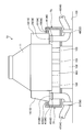
- FIG. 6 is a partially cutaway perspective view showing the overall configuration of the condenser.
- the condenser 10 includes a housing 11, inlet water chambers 12 and 13, outlet water chambers 14 and 15, and heat transfer tube groups 16 and 17.
- the housing 11 is box-shaped and has a hollow shape with a truncated pyramid at the top.
- a steam inlet 21 through which used steam flows is formed at the top, and the steam is condensed at the bottom.
- a condensate drain 22 for discharging water (condensate) is formed.
- the tube plate 23, 24 is fixed to each end portion in the longitudinal direction (horizontal direction) of the housing 11.
- the inlet water chamber 12 and the outlet water chamber 15 are fixed adjacent to one tube plate 24 in the horizontal direction, and the outlet water chamber 14 and the inlet water chamber 13 are fixed adjacent to the other tube plate 23.
- the inlet water chamber 12 and the outlet water chamber 14 are disposed at positions that are horizontally opposed via the housing 11, and the inlet water chamber 13 and the outlet water chamber 15 are horizontally opposed via the housing 11. Placed in position.
- the inlet water chambers 12 and 13 are provided with inlet nozzles 25 and 26 at the lower part, and the outlet water chambers 14 and 15 are provided with outlet nozzles 27 and 28 (see FIG. 1) at the lower part.
- the inlet water chamber 12 and the outlet water chamber 14 are connected by a heat transfer tube group 16 in the housing 11, and the inlet water chamber 13 and the outlet water chamber 15 are connected by a heat transfer tube group 17 in the housing 11.
- the heat transfer tube group 16 is composed of a plurality of heat transfer tubes 31 and is arranged inside the housing 11 and supported so that one end portion penetrates the tube plate 23 and the other end portion penetrates the tube plate 24. Has been. Therefore, the inlet water chamber 12 and the outlet water chamber 14 are communicated with each other by a plurality of heat transfer tubes 31.
- the heat transfer tube group 17 includes a plurality of heat transfer tubes 32, is disposed inside the housing 11, is supported so that one end portion penetrates the tube plate 23, and the other end portion penetrates the tube plate 24. It is supported by. Therefore, the inlet water chamber 13 and the outlet water chamber 15 communicate with each other through a plurality of heat transfer tubes 32.
- the housing 11 has a plurality of tube support plates 33 and 34 arranged therein at predetermined intervals in the longitudinal direction of the heat transfer tubes 31 and 32.
- the lower portion of the tube support plate 33 is supported on the bottom portion of the housing 11 by the support member 35, and the lower portion of the tube support plate 34 is supported on the bottom portion and the side portion of the housing 11 by a support member (not shown).
- the intermediate portion of the heat transfer tube 31 is supported through the tube support plates 33, and the intermediate portion of the heat transfer tube 32 is supported through the tube support plates 34.
- the steam S enters the housing 11 through the steam inlet 21, flows downward in the housing 11 in the vertical direction, and is discharged as condensate W from the condensate drain 22.
- seawater C as cooling water is introduced into the inlet water chambers 12 and 13 from the inlet nozzles 25 and 26, flows along the heat transfer tubes 31 and 32 in the horizontal direction, and flows into the outlet water chambers 14 and 15. The gas is discharged from the outlet nozzles 27 and 28.
- the steam S flows vertically in the housing 11 and the seawater C flows horizontally in the heat transfer tubes 31 and 32, the flow of the steam S and the flow of the seawater C intersect without mixing. Then, heat exchange is performed. That is, the steam S is cooled by the seawater C flowing through the heat transfer tubes 31 and 32 and falls into the housing 11 as condensate W.
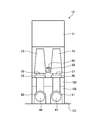
- FIG. 1 is a front view showing the condenser of the first embodiment
- FIG. 2 is a plan view showing the condenser
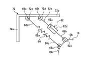
- FIG. 3 is a schematic view showing the attachment structure of the damping member and the restoring member
- FIG. It is the schematic showing the modification of the attachment structure of a damping member and a restoring member.
- a concrete foundation base (concrete structure) 102 having a rectangular block shape is installed on the installation surface 101 having a planar shape to which concrete is attached.
- the housing 11 is installed and supported on the concrete base 102 via a plurality of concrete legs 103.
- the inlet water chambers 12 and 13 have inlet nozzles 25 and 26 connected to intake pipes 43 and 44 via expansion joints 41 and 42, and the outlet water chambers 14 and 15 have expansion nozzles 45 and 46 with outlet nozzles 27 and 28. It is connected to the drain pipes 47 and 48 via.
- the intake pipes 43 and 44 are fixed to the installation surface 101 by fixing brackets 49 and 50, and the drain pipes 47 and 48 are fixed to the installation surface 101 by fixing brackets 51 and 52.
- the condenser 10 configured as described above has a natural frequency, that is, a natural vibration displacement mode, which is determined by the shape and thickness of each component, the connection structure, and the like.
- FIG. 7 is a schematic diagram illustrating the natural vibration displacement mode of the condenser.
- the housing 11 is fixed on the concrete foundation 102 via a plurality of concrete legs 103, the intake pipes 43 and 44 are fixed to the installation surface 101 by fixing brackets 49 and 50, and the drain pipe 47, 48 is fixed to the installation surface 101 by fixing brackets 51 and 52. Therefore, the condenser 10 has a natural vibration displacement mode as shown in FIG. 7, for example. That is, when an earthquake occurs, the housing 11 is displaced in parallel in the horizontal direction and bends, and the inlet water chambers 12 and 13 and the outlet water chambers 14 and 15 are horizontally supported with a support shaft along the vertical direction. Displace to rotate in the direction.
- the housing 11, the intake pipes 43 and 44, and the drain pipes 47 and 48 are fixed to the installation surface 101 (concrete foundation 102) having a predetermined rigidity, they are hardly displaced.
- the inlet water chambers 12 and 13 and the outlet water chambers 14 and 15 are relatively displaced.
- the displacement amounts of the inlet water chambers 12 and 13 and the outlet water chambers 14 and 15 are increased, the relative displacement amounts of the inlet nozzles 25 and 26 and the intake pipes 43 and 44 are increased, and the outlet nozzles 27 and 28 and the drainage are discharged.
- the amount of relative displacement with the tubes 47 and 48 increases. Then, stress acts on each expansion joint 41, 42, 45, 46, and there is a possibility that it will be deformed or damaged.
- the condenser 10 includes damping members 61, 62, 63, 64 that attenuate the displacement of the inlet water chambers 12, 13 and the outlet water chambers 14, 15 as shown in FIGS. And restoration members 65, 66, 67, 68 for restoring the positions of the inlet water chambers 12, 13 and the outlet water chambers 14, 15.
- a support structure 71 is erected adjacent to the inlet water chamber 12 and the outlet water chamber 15, and a support structure 72 is erected adjacent to the inlet water chamber 13 and the outlet water chamber 14.
- the support structures 71 and 72 are erected on the installation surface 101 so as to surround the inlet water chamber 12 and the outlet water chamber 15, and the inlet water chamber 13 and the outlet water chamber 14, respectively.
- Each support structure 71, 72 includes a pair of side walls 71 b, 71 c, 72 b that are coupled to each end of the intermediate walls 71 a, 72 a along the longitudinal direction of the housing 11. , 72c.
- Each support structure 71, 72 has a U-shape in plan view due to the intermediate walls 71a, 72a and the side walls 71b, 71c, 72b, 72c.
- the damping member 61 and the restoring member 65 are interposed between the inlet water chamber 12 and the supporting structure 71 (side wall 71b), and the damping member 64 and the restoring member 68 are connected to the outlet water chamber 15 and the supporting structure 71 (side wall). 71c).
- the damping member 62 and the restoring member 66 are interposed between the inlet water chamber 13 and the support structure 72 (side wall 72c), and the damping member 63 and the restoring member 67 are disposed between the outlet water chamber 14 and the support structure 72. It is interposed between (side wall 72b).
- the inlet water chambers 12 and 13 and the outlet water chambers 14 and 15 are formed long along the vertical direction, and the inlet nozzles 25 and 26 and the outlet nozzles 27 and 28 are connected to the expansion joints 41, 42, 45, and 46, respectively.
- the ends of the damping members 61, 62, 63, 64 and the restoring members 65, 66, 67, 68 are in the vicinity of the expansion joints 41, 42, 45, 46 in the inlet water chambers 12, 13 and the outlet water chambers 14, 15. It is connected.
- the damping members 61, 62, 63, 64 and the restoring members 65, 66, 67, 68 are connected at the ends below the intermediate positions in the vertical direction in the inlet water chambers 12, 13 and the outlet water chambers 14, 15.
- the damping member 62 is an oil damper
- a rod 62 b on the piston 62 a side is rotatably supported by a support pin 62 c on a bracket 13 a fixed to the inlet water chamber 13.
- a rod 62e on the 62d side is rotatably supported by a support pin 62f on a bracket 72d fixed to the support structure 72.
- the support pins 62c and 62f are along the vertical direction, and the attenuation member 62 can be rotated in the horizontal direction.
- the restoring member 66 is a tension spring (metal spring), and one end portion 66b of the spring member 66a is rotatably supported by a support pin 66c on a bracket 13b fixed to the inlet water chamber 13, and the other end portion. 66d is rotatably supported by a support pin 66e on a bracket 72e fixed to the support structure 72. In this case, the support pins 66c and 66e are along the vertical direction, and the attenuation member 66 can be rotated in the horizontal direction.
- damping members 61, 63, and 64 and the restoring members 65, 67, and 68 are similarly rotatably supported at their ends by support pins.
- the damping members 61, 62, 63, 64 and the restoring members 65, 66, 67, 68 are arranged with a predetermined inclination angle with respect to the outer surface of the housing 11 having a rectangular shape in plan view.
- the arrangement direction of the damping members 61, 62, 63, 64 and the restoring members 65, 66, 67, 68 is set in accordance with the natural vibration displacement mode of the condenser 10 described above.
- the housing 11, the inlet water chambers 12, 13 and the outlet water chambers 14, 15 are different from the intake pipes 43, 44 and the drain pipes 47, 48. Displace in the direction. At this time, the displacement of the inlet water chambers 12 and 13 and the outlet water chambers 14 and 15 is attenuated by the damping members 61, 62, 63 and 64, and restored to the original positions by the restoring members 65, 66, 67 and 68.
- the arrangement direction of the damping members 61, 62, 63, 64 and the restoring members 65, 66, 67, 68 is not limited to the above-described direction.
- the damping member 62 ⁇ / b> A and the restoring member 66 ⁇ / b> A are disposed at right angles to the end surface of the housing 11 that is rectangular in plan view, and the damping member 62 ⁇ / b> B and the restoring member 66 ⁇ / b> B are the end surface of the housing 11. It is arranged in parallel to.
- the natural vibration displacement mode of the condenser is analyzed in advance, and the arrangement direction of the damping member and the restoring member may be set according to the natural vibration displacement mode of the condenser.
- the damping member and the restoring member may be arranged to be inclined up and down with respect to the horizontal direction without being arranged horizontally.
- the rotation direction of the end portions of the damping member and the restoring member is not limited to the horizontal direction, and may be supported so as to be swingable in all directions by supporting the spherical surface.
- FIG. 5 is a front view illustrating a modification of the condenser according to the first embodiment.
- the condenser 10 has a support structure 73 standing adjacent to the inlet water chamber 12 and the outlet water chamber 15, and adjacent to the inlet water chamber 13 and the outlet water chamber 14.
- a support structure 74 is erected.
- the support structures 73 and 74 are provided on the concrete foundation 102 so as to surround the inlet water chamber 12 and the outlet water chamber 15, and the inlet water chamber 13 and the outlet water chamber 14, respectively.
- the support structures 71, 72, 73, 74 are provided on the installation surface 101 and the concrete base 102, but if there are structures such as existing buildings around the condenser 10, The structure may be applied as a support structure.
- the housing 11, the inlet water chambers 12 and 13, the outlet water chambers 14 and 15, the intake pipes 43 and 44, and the drain pipes 47 and 48 are in different directions. Displacement can occur.
- the damping members 61, 62, 63, 64 attenuate the displacement of the inlet water chambers 12, 13 and the outlet water chambers 14, 15, and the restoring members 65, 66, 67, 68 are the inlet water chambers 12, 13 and the outlet. The positions of the water chambers 14 and 15 are restored.
- the intake pipes 43 and 44 and the drain pipes 47 and 48 are supported on the installation surface 101, and support structures 71 and 72 having predetermined rigidity set in advance on the installation surface 101 are provided.
- the damping members 61, 62, 63, 64 and the restoring members 65, 66, 67, 68 are interposed between the inlet water chambers 12, 13 and the outlet water chambers 14, 15 and the support structures 71, 72. ing.
- the displacement of the inlet water chambers 12 and 13 and the outlet water chambers 14 and 15 is reduced with respect to the installation surface 101 and restored to the original position, and the inlet water chambers 12 and 13 and the outlet water chambers 14 and 15
- the relative displacement with the intake pipes 43 and 44 and the drain pipes 47 and 48 can be suppressed appropriately.
- the concrete base 102 is installed on the installation surface 101, and the housing 11 and the supporting structures 73 and 74 are supported by the concrete base 102. Therefore, the displacement of the inlet water chambers 12 and 13 and the outlet water chambers 14 and 15 is reduced with respect to the installation surface 101 and restored to the original position, and the inlet water chambers 12 and 13 and the outlet water chambers 14 and 15 The relative displacement with the intake pipes 43 and 44 and the drain pipes 47 and 48 can be suppressed appropriately. Moreover, the support structures 73 and 74 can be reduced in size.
- the inlet water chambers 12 and 13 and the outlet water chambers 14 and 15 are erected so as to be surrounded by the support structures 71 and 72. Accordingly, the degree of freedom of arranging the damping members 61, 62, 63, 64 and the restoring members 65, 66, 67, 68 according to the natural vibration displacement mode of the condenser 10 is increased, and the inlet water chambers 12, 13 and the outlet water are arranged. The relative displacement between the chambers 14 and 15 and the intake pipes 43 and 44 and the drain pipes 47 and 48 can be appropriately suppressed.
- the end portions of the damping members 61, 62, 63, 64 and the restoring members 65, 66, 67, 68 are rotatably supported. Therefore, when the damping members 61, 62, 63, 64 and the restoring members 65, 66, 67, 68 reduce the displacement of the inlet water chambers 12, 13 and the outlet water chambers 14, 15 and restore them to their original positions, the end members By rotating the portion, it is possible to suppress stress from being concentrated on the end portion.
- the inlet water chambers 12 and 13 and the outlet water chambers 14 and 15 are formed long along the vertical direction, and the inlet nozzles 25 and 26 and the outlet nozzles 27 and 28 provided in the lower part are expanded and contracted.
- the joints 41, 42, 45 and 46 are connected to the intake pipes 43 and 44 and the drain pipes 47 and 48, and the end portions of the damping members 61, 62, 63 and 64 and the restoring members 65, 66, 67 and 68 are connected to the inlet water chamber. 12 and 13 and the outlet water chambers 14 and 15 are connected to the vicinity of the expansion joints 41, 42, 45 and 46.
- FIG. 8 is a plan view showing the condenser according to the second embodiment
- FIG. 9 is a side view showing the condenser.
- symbol is attached
- the condenser 10 includes an inlet water chamber 12 and an outlet water chamber 15 at one end of the housing 11, and an inlet water chamber 13 at the other end.
- An outlet water chamber 14 is provided, a damping member 81 and a restoring member 83 are interposed between the adjacent inlet water chamber 12 and the outlet water chamber 15, and between the adjacent inlet water chamber 13 and the outlet water chamber 14.
- a damping member 82 and a restoring member 84 are interposed.
- the housing 11, the inlet water chambers 12, 13 and the outlet water chambers 14, 15 are different from the intake pipes 43, 44 and the drain pipes 47, 48. Displace in the direction. Further, the adjacent inlet water chamber 12 and the outlet water chamber 15 or the adjacent inlet water chamber 13 and the outlet water chamber 14 are displaced in different directions according to a predetermined natural vibration displacement mode. For example, the inlet water chamber 12 and the outlet water chamber 15, and the inlet water chamber 13 and the outlet water chamber 14 approach or separate from each other. At this time, the displacement of the inlet water chamber 12 and the outlet water chamber 15 is attenuated by the attenuation member 81 and restored to the original position by the restoration member 83.
- the displacement of the inlet water chamber 13 and the outlet water chamber 14 is attenuated by the damping member 82 and restored to the original position by the restoring member 84. Therefore, the displacements of the inlet water chambers 12 and 13 and the outlet water chambers 14 and 15 are reduced and restored to their original positions, and the inlet nozzles 25 and 26 and the outlet nozzles 27 and 28 and the expansion joints 41, 42, The relative displacement with respect to 45, 46 is suppressed, the stress acting on the expansion joints 41, 42, 45, 46 is reduced, and breakage can be prevented.
- the damping member 81 and the restoring member 83 are interposed between the adjacent inlet water chamber 12 and the outlet water chamber 15, and the adjacent inlet water chamber 13
- a damping member 82 and a restoring member 84 are interposed between the outlet water chamber 14.
- the damping members 81 and 82 attenuate the displacement of the inlet water chambers 12 and 13 and the outlet water chambers 14 and 15, and the restoring members 83 and 84 return the inlet water chambers 12 and 13 and the outlet water chambers 14 and 15 to their original positions. Restore to. Therefore, the displacement of the inlet water chambers 12 and 13 and the outlet water chambers 14 and 15 is reduced and restored to the original position, and the inlet water chambers 12 and 13 and the outlet water chambers 14 and 15 and the intake pipes 43 and 44 and The relative displacement with the drain pipes 47 and 48 is suppressed, and the stress acting on the expansion joints 41, 42, 45 and 46 is reduced. As a result, the earthquake resistance of the condenser 10 can be improved.
- FIG. 10 is a plan view showing a condenser according to the third embodiment
- FIG. 11 is a side view showing the condenser.
- symbol is attached
- each condenser 10 includes a housing 11, inlet water chambers 12 and 13, outlet water chambers 14 and 15, and heat transfer tube groups 16 and 17. Attenuating members 91 and 92 and restoring members 93 and 94 are interposed between the inlet water chambers 12 and 13 and the outlet water chambers 14 and 15 in the adjacent housings 11.
- damping member 91 and the restoring member 93 are interposed between the inlet water chamber 12 of one condenser 10 and the outlet water chamber 15 of the other condenser 10, and the outlet water of one condenser 10 is disposed.
- a damping member 92 and a restoring member 94 are interposed between the chamber 14 and the inlet water chamber 13 of the other condenser 10.
- the adjacent condenser 10 and the other condenser 10 move in the natural vibration displacement mode according to the amount of water in each housing 11, the housing 11, the inlet water chambers 12, 13 and the outlet water
- the chambers 14, 15 and the intake pipes 43, 44 and the drain pipes 47, 48 are displaced in different directions.
- a relative displacement occurs between the adjacent inlet water chamber 12 and the outlet water chamber 15, and between the adjacent inlet water chamber 13 and the outlet water chamber 14.
- the displacement of the inlet water chamber 12 and the outlet water chamber 15 is attenuated by the damping member 91 and restored to the original position by the restoring member 93.
- the displacement of the inlet water chamber 13 and the outlet water chamber 14 is attenuated by the attenuation member 92 and restored to the original position by the restoration member 94. Therefore, the displacements of the inlet water chambers 12 and 13 and the outlet water chambers 14 and 15 are reduced and restored to their original positions, and the inlet nozzles 25 and 26 and the outlet nozzles 27 and 28 and the expansion joints 41, 42, The relative displacement with respect to 45, 46 is suppressed, the stress acting on the expansion joints 41, 42, 45, 46 is reduced, and breakage can be prevented.
- the damping member 91 and the restoring member 93 are interposed between the inlet water chamber 12 and the outlet water chamber 15 of the adjacent condenser 10 so as to be adjacent to each other.
- a damping member 92 and a restoring member 94 are interposed between the inlet water chamber 13 and the outlet water chamber 14.
- the damping members 91 and 92 attenuate the displacement of the inlet water chambers 12 and 13 and the outlet water chambers 14 and 15, and the restoring members 93 and 94 return the inlet water chambers 12 and 13 and the outlet water chambers 14 and 15 to their original positions. Restore to. Therefore, the displacement of the inlet water chambers 12 and 13 and the outlet water chambers 14 and 15 is reduced and restored to the original position, and the inlet water chambers 12 and 13 and the outlet water chambers 14 and 15 and the intake pipes 43 and 44 and The relative displacement with the drain pipes 47 and 48 is suppressed, and the stress acting on the expansion joints 41, 42, 45 and 46 is reduced. As a result, the earthquake resistance of the condenser 10 can be improved.
- the damping member is an oil damper
- the restoring member is a tension spring
- the present invention is not limited to this configuration.
- an urging member or a rubber member made of synthetic resin may be applied in addition to the tension spring.
- damping members and restoring members are arranged, but they may be arranged separately as different numbers.
- the condenser of the present invention has been described as being applied as a condenser of a nuclear power plant having a pressurized water reactor.
- the condenser is applied to a condenser in another type of nuclear reactor. You can also Moreover, you may apply as condensers, such as not only a nuclear power plant but a thermal power plant and a geothermal power plant.
Landscapes
- Engineering & Computer Science (AREA)
- General Engineering & Computer Science (AREA)
- Mechanical Engineering (AREA)
- Physics & Mathematics (AREA)
- Thermal Sciences (AREA)
- Acoustics & Sound (AREA)
- Aviation & Aerospace Engineering (AREA)
- Geometry (AREA)
- Vibration Prevention Devices (AREA)
- Heat-Exchange Devices With Radiators And Conduit Assemblies (AREA)
- Structure Of Emergency Protection For Nuclear Reactors (AREA)
Abstract
Description
第1実施形態の復水器は、例えば、原子力発電プラントに適用されたものであり、原子力発電プラントは、原子炉格納容器内に格納された加圧水型原子炉及び蒸気発生器、蒸気タービン、発電機、復水器などにより構成されている。なお、加圧水型原子炉は、軽水を原子炉冷却材及び中性子減速材として使用し、炉心全体にわたって沸騰しない高温高圧水とし、この高温高圧水を蒸気発生器に送って熱交換により蒸気を発生させるものである。
図8は、第2実施形態の復水器を表す平面図、図9は、復水器を表す側面図である。なお、上述した実施形態と同様の機能を有する部材には、同一の符号を付して詳細な説明は省略する。
図10は、第3実施形態の復水器を表す平面図、図11は、復水器を表す側面図である。なお、上述した実施形態と同様の機能を有する部材には、同一の符号を付して詳細な説明は省略する。
11 ハウジング
12,13 入口水室
14,15 出口水室
16,17 伝熱管群
21 蒸気流入口
22 復水排出口
23,24 管板
25,26 入口ノズル
27,28 出口ノズル
31,32 伝熱管
33,34 管支持板
35 支持部材
37 非凝縮ガス排出管
41,42,45,46 伸縮継手
43,44 取水管
47,48 排水管
49,50,51,52 固定金具
61,62,62A,62B,63,64,81,82,91,92 減衰部材
65,66,66A,66B,67,68,83,84,93,94 復元部材
71,72,73,74 支持構造物
101 設置面
102 コンクリート基礎台(コンクリート構造物)
103 コンクリート脚部
S 蒸気
C 海水
W 復水
Claims (8)
- 中空形状をなして蒸気の流入口と復水の排出口が設けられるハウジングと、
前記ハウジングにおける各端部に設けられる入口水室及び出口水室と、
前記ハウジングの内部で前記入口水室と前記出口水室を連結して内部に冷却媒体が流れる多数の伝熱管と、
前記入口水室及び前記出口水室にそれぞれ伸縮継手を介して連結される取水管及び排水管と、
前記入口水室及び前記出口水室の変位を減衰する減衰部材と、
前記入口水室及び前記出口水室の位置を復元する復元部材と、
を有することを特徴とする復水器。 - 前記ハウジングと前記取水管及び前記排水管は、設置面に支持され、前記設置面に予め設定された所定の剛性を有する支持構造物が立設され、前記減衰部材と前記復元部材は、前記入口水室と前記支持構造物との間に介装されると共に、前記出口水室と前記支持構造物との間に介装されることを特徴とする請求項1に記載の復水器。
- 前記設置面にコンクリート構造物が設置され、前記ハウジングと前記支持構造物は、前記コンクリート構造物に支持されることを特徴とする請求項2に記載の復水器。
- 前記支持構造物は、前記入口水室及び前記出口水室を囲うように立設されることを特徴とする請求項2または請求項3に記載の復水器。
- 前記入口水室及び前記出口水室は、1個の前記ハウジングに対して複数組設けられ、前記ハウジングにおける端部に隣接して設けられ、前記減衰部材と前記復元部材は、隣接する前記入口水室と前記出口水室との間に介装されることを特徴とする請求項1から請求項4のいずれか一項に記載の復水器。
- 前記減衰部材と前記復元部材は、隣接する各ハウジングにおける前記入口水室と前記出口水室との間に介装されることを特徴とする請求項1から請求項5のいずれか一項に記載の復水器。
- 前記減衰部材と前記復元部材は、端部が回動自在に支持されることを特徴とする請求項1から請求項6のいずれか一項に記載の復水器。
- 前記入口水室及び前記出口水室は、鉛直方向に沿って長く形成され、下部に設けられる入口ノズル及び出口ノズルが前記伸縮継手を介して取水管及び排水管に連結され、前記減衰部材と前記復元部材は、端部が前記入口水室及び前記出口水室における前記伸縮継手の近傍に連結されることを特徴とする請求項1から請求項7のいずれか一項に記載の復水器。
Priority Applications (4)
| Application Number | Priority Date | Filing Date | Title |
|---|---|---|---|
| KR1020177020921A KR101918884B1 (ko) | 2015-03-10 | 2016-03-08 | 복수기 |
| US15/546,117 US10527363B2 (en) | 2015-03-10 | 2016-03-08 | Condenser |
| CN201680007293.3A CN107208496B (zh) | 2015-03-10 | 2016-03-08 | 冷凝器 |
| DE112016001136.9T DE112016001136B4 (de) | 2015-03-10 | 2016-03-08 | Verflüssigerinstallation in einer Kraftwerkanlage |
Applications Claiming Priority (2)
| Application Number | Priority Date | Filing Date | Title |
|---|---|---|---|
| JP2015-047696 | 2015-03-10 | ||
| JP2015047696A JP6510278B2 (ja) | 2015-03-10 | 2015-03-10 | 復水器 |
Publications (1)
| Publication Number | Publication Date |
|---|---|
| WO2016143773A1 true WO2016143773A1 (ja) | 2016-09-15 |
Family
ID=56880286
Family Applications (1)
| Application Number | Title | Priority Date | Filing Date |
|---|---|---|---|
| PCT/JP2016/057094 Ceased WO2016143773A1 (ja) | 2015-03-10 | 2016-03-08 | 復水器 |
Country Status (6)
| Country | Link |
|---|---|
| US (1) | US10527363B2 (ja) |
| JP (1) | JP6510278B2 (ja) |
| KR (1) | KR101918884B1 (ja) |
| CN (1) | CN107208496B (ja) |
| DE (1) | DE112016001136B4 (ja) |
| WO (1) | WO2016143773A1 (ja) |
Cited By (1)
| Publication number | Priority date | Publication date | Assignee | Title |
|---|---|---|---|---|
| CN108533668A (zh) * | 2018-03-29 | 2018-09-14 | 宁波希奇服饰有限公司 | 一种具有自适应减震装置的布料脱水机 |
Families Citing this family (3)
| Publication number | Priority date | Publication date | Assignee | Title |
|---|---|---|---|---|
| CN109026209B (zh) * | 2018-09-26 | 2021-02-23 | 江苏海事职业技术学院 | 一种带有摆动支承结构的汽轮机 |
| KR102246071B1 (ko) | 2019-09-03 | 2021-04-29 | 한국남동발전 주식회사 | 발전소 복수기 출구 기준유량 추정 방법 및 시스템 |
| CN114688890B (zh) * | 2022-05-31 | 2022-09-13 | 杭州国能汽轮工程有限公司 | 一种凝汽器 |
Citations (6)
| Publication number | Priority date | Publication date | Assignee | Title |
|---|---|---|---|---|
| JPS53102406A (en) * | 1977-02-18 | 1978-09-06 | Toshiba Corp | Steam condencser |
| JPS61128559U (ja) * | 1985-01-30 | 1986-08-12 | ||
| JP2008064107A (ja) * | 2007-10-19 | 2008-03-21 | Mitsubishi Heavy Ind Ltd | 機器の輸送及び据付方法 |
| JP2011220074A (ja) * | 2010-04-14 | 2011-11-04 | Mitsubishi Heavy Industries Bridge & Steel Structures Engineering Co Ltd | 塔状構造物の制震構造 |
| JP2012167702A (ja) * | 2011-02-10 | 2012-09-06 | Toshiba Corp | 配管支持装置およびプラント |
| JP2013164245A (ja) * | 2012-02-13 | 2013-08-22 | Toshiba Corp | 復水器 |
Family Cites Families (9)
| Publication number | Priority date | Publication date | Assignee | Title |
|---|---|---|---|---|
| AT30767B (de) | 1906-10-05 | 1907-11-25 | Arthur Nathan | Schloß für Eisenbahnwagentüren u. dgl. |
| US4008757A (en) * | 1975-09-22 | 1977-02-22 | The Babcock & Wilcox Company | Industrial technique |
| US4286549A (en) * | 1979-12-03 | 1981-09-01 | Foster Wheeler Energy Corporation | Steam generator support system |
| JPS61128559A (ja) | 1984-11-28 | 1986-06-16 | Hoya Corp | 固体撮像素子アツセンブリ |
| FR2697052B1 (fr) * | 1992-10-21 | 1994-12-09 | Alsthom Gec | Enveloppe en béton d'un condenseur pour module basse pression à structure indépendante. |
| JP4191322B2 (ja) | 1999-06-15 | 2008-12-03 | 三菱重工業株式会社 | 蒸気タービンプラントの据付方法 |
| AU2003252325B2 (en) | 2003-07-30 | 2007-06-07 | Mitsubishi Hitachi Power Systems, Ltd. | Heat exchanger tube panel module, and method of constructing exhaust heat recovery boiler using the module |
| AU2003252323A1 (en) | 2003-07-30 | 2005-02-15 | Babcock-Hitachi Kabushiki Kaisha | Heat exchanger tube panel module, and method of constructing exhaust heat recovery boiler using the module |
| US8194815B2 (en) | 2009-03-30 | 2012-06-05 | Ge-Hitachi Nuclear Energy Americas, Llc | Apparatus and system for dampening the vibration experienced by an object |
-
2015
- 2015-03-10 JP JP2015047696A patent/JP6510278B2/ja not_active Expired - Fee Related
-
2016
- 2016-03-08 DE DE112016001136.9T patent/DE112016001136B4/de active Active
- 2016-03-08 CN CN201680007293.3A patent/CN107208496B/zh active Active
- 2016-03-08 US US15/546,117 patent/US10527363B2/en active Active
- 2016-03-08 WO PCT/JP2016/057094 patent/WO2016143773A1/ja not_active Ceased
- 2016-03-08 KR KR1020177020921A patent/KR101918884B1/ko active Active
Patent Citations (6)
| Publication number | Priority date | Publication date | Assignee | Title |
|---|---|---|---|---|
| JPS53102406A (en) * | 1977-02-18 | 1978-09-06 | Toshiba Corp | Steam condencser |
| JPS61128559U (ja) * | 1985-01-30 | 1986-08-12 | ||
| JP2008064107A (ja) * | 2007-10-19 | 2008-03-21 | Mitsubishi Heavy Ind Ltd | 機器の輸送及び据付方法 |
| JP2011220074A (ja) * | 2010-04-14 | 2011-11-04 | Mitsubishi Heavy Industries Bridge & Steel Structures Engineering Co Ltd | 塔状構造物の制震構造 |
| JP2012167702A (ja) * | 2011-02-10 | 2012-09-06 | Toshiba Corp | 配管支持装置およびプラント |
| JP2013164245A (ja) * | 2012-02-13 | 2013-08-22 | Toshiba Corp | 復水器 |
Cited By (1)
| Publication number | Priority date | Publication date | Assignee | Title |
|---|---|---|---|---|
| CN108533668A (zh) * | 2018-03-29 | 2018-09-14 | 宁波希奇服饰有限公司 | 一种具有自适应减震装置的布料脱水机 |
Also Published As
| Publication number | Publication date |
|---|---|
| CN107208496B (zh) | 2019-07-09 |
| JP2016166596A (ja) | 2016-09-15 |
| JP6510278B2 (ja) | 2019-05-08 |
| KR101918884B1 (ko) | 2018-11-14 |
| DE112016001136B4 (de) | 2023-07-27 |
| KR20170100631A (ko) | 2017-09-04 |
| US20180023902A1 (en) | 2018-01-25 |
| DE112016001136T5 (de) | 2017-11-16 |
| CN107208496A (zh) | 2017-09-26 |
| US10527363B2 (en) | 2020-01-07 |
Similar Documents
| Publication | Publication Date | Title |
|---|---|---|
| CN101868676B (zh) | 可由销售店组装的太阳能吸收器热交换器 | |
| JP2016166596A (ja) | 復水器 | |
| US11901088B2 (en) | Method of heating primary coolant outside of primary coolant loop during a reactor startup operation | |
| JPWO2014030752A1 (ja) | 伝熱管の振動抑制装置及び蒸気発生器 | |
| EP2366182A1 (en) | Seismically isolated containment vessel | |
| KR20160101939A (ko) | 증기 발생기 튜브 지지체 | |
| KR20160014015A (ko) | 수동형 원자로 냉각시스템 | |
| JP2013164245A (ja) | 復水器 | |
| JP6021317B2 (ja) | 使用済燃料ラックの補強構造 | |
| US12512230B2 (en) | Passively-cooled spent nuclear fuel pool system | |
| JP6122744B2 (ja) | ボイラ制振用のサイスミックタイおよびこれを用いたボイラ耐震構造体 | |
| JP6809807B2 (ja) | 配管構造、及びボイラシステム | |
| KR102082015B1 (ko) | 브레이스가 구비된 하프모듈 박스 | |
| JP5901244B2 (ja) | 蒸気発生器 | |
| JP2015169265A (ja) | 配管取合機器の支持構造 | |
| JP4076014B2 (ja) | 排熱回収ボイラ及びその据付方法 | |
| JP6884635B2 (ja) | 耐震補強方法 | |
| CN223388563U (zh) | 一种锅炉止震结构 | |
| JPH11264501A (ja) | 排熱回収ボイラ | |
| JP6869062B2 (ja) | 制振コネクタ装置 | |
| JP7604003B2 (ja) | 原子炉システム | |
| JP6484065B2 (ja) | 使用済燃料ラックおよび原子力発電プラントならびに使用済燃料ラックの運用方法 | |
| JP6276556B2 (ja) | 燃料貯蔵設備 | |
| JP6109579B2 (ja) | 配管取合機器の支持構造 | |
| CN108885910B (zh) | 汽轮机建筑物及核电站 |
Legal Events
| Date | Code | Title | Description |
|---|---|---|---|
| 121 | Ep: the epo has been informed by wipo that ep was designated in this application |
Ref document number: 16761741 Country of ref document: EP Kind code of ref document: A1 |
|
| WWE | Wipo information: entry into national phase |
Ref document number: 15546117 Country of ref document: US |
|
| ENP | Entry into the national phase |
Ref document number: 20177020921 Country of ref document: KR Kind code of ref document: A |
|
| WWE | Wipo information: entry into national phase |
Ref document number: 112016001136 Country of ref document: DE |
|
| 122 | Ep: pct application non-entry in european phase |
Ref document number: 16761741 Country of ref document: EP Kind code of ref document: A1 |