WO2016143256A1 - Corps volant - Google Patents
Corps volant Download PDFInfo
- Publication number
- WO2016143256A1 WO2016143256A1 PCT/JP2016/000684 JP2016000684W WO2016143256A1 WO 2016143256 A1 WO2016143256 A1 WO 2016143256A1 JP 2016000684 W JP2016000684 W JP 2016000684W WO 2016143256 A1 WO2016143256 A1 WO 2016143256A1
- Authority
- WO
- WIPO (PCT)
- Prior art keywords
- flying
- flying object
- light spot
- controller
- light
- Prior art date
Links
Images


Classifications
-
- G—PHYSICS
- G08—SIGNALLING
- G08G—TRAFFIC CONTROL SYSTEMS
- G08G5/00—Traffic control systems for aircraft, e.g. air-traffic control [ATC]
- G08G5/04—Anti-collision systems
- G08G5/045—Navigation or guidance aids, e.g. determination of anti-collision manoeuvers
-
- B—PERFORMING OPERATIONS; TRANSPORTING
- B64—AIRCRAFT; AVIATION; COSMONAUTICS
- B64C—AEROPLANES; HELICOPTERS
- B64C27/00—Rotorcraft; Rotors peculiar thereto
- B64C27/04—Helicopters
- B64C27/08—Helicopters with two or more rotors
-
- B—PERFORMING OPERATIONS; TRANSPORTING
- B64—AIRCRAFT; AVIATION; COSMONAUTICS
- B64C—AEROPLANES; HELICOPTERS
- B64C39/00—Aircraft not otherwise provided for
- B64C39/02—Aircraft not otherwise provided for characterised by special use
- B64C39/024—Aircraft not otherwise provided for characterised by special use of the remote controlled vehicle type, i.e. RPV
-
- B—PERFORMING OPERATIONS; TRANSPORTING
- B64—AIRCRAFT; AVIATION; COSMONAUTICS
- B64D—EQUIPMENT FOR FITTING IN OR TO AIRCRAFT; FLIGHT SUITS; PARACHUTES; ARRANGEMENTS OR MOUNTING OF POWER PLANTS OR PROPULSION TRANSMISSIONS IN AIRCRAFT
- B64D47/00—Equipment not otherwise provided for
- B64D47/02—Arrangements or adaptations of signal or lighting devices
- B64D47/06—Arrangements or adaptations of signal or lighting devices for indicating aircraft presence
-
- B—PERFORMING OPERATIONS; TRANSPORTING
- B64—AIRCRAFT; AVIATION; COSMONAUTICS
- B64D—EQUIPMENT FOR FITTING IN OR TO AIRCRAFT; FLIGHT SUITS; PARACHUTES; ARRANGEMENTS OR MOUNTING OF POWER PLANTS OR PROPULSION TRANSMISSIONS IN AIRCRAFT
- B64D47/00—Equipment not otherwise provided for
- B64D47/08—Arrangements of cameras
-
- B—PERFORMING OPERATIONS; TRANSPORTING
- B64—AIRCRAFT; AVIATION; COSMONAUTICS
- B64U—UNMANNED AERIAL VEHICLES [UAV]; EQUIPMENT THEREFOR
- B64U10/00—Type of UAV
- B64U10/10—Rotorcrafts
- B64U10/13—Flying platforms
- B64U10/14—Flying platforms with four distinct rotor axes, e.g. quadcopters
-
- G—PHYSICS
- G05—CONTROLLING; REGULATING
- G05D—SYSTEMS FOR CONTROLLING OR REGULATING NON-ELECTRIC VARIABLES
- G05D1/00—Control of position, course or altitude of land, water, air, or space vehicles, e.g. automatic pilot
- G05D1/0011—Control of position, course or altitude of land, water, air, or space vehicles, e.g. automatic pilot associated with a remote control arrangement
- G05D1/0027—Control of position, course or altitude of land, water, air, or space vehicles, e.g. automatic pilot associated with a remote control arrangement involving a plurality of vehicles, e.g. fleet or convoy travelling
-
- G—PHYSICS
- G05—CONTROLLING; REGULATING
- G05D—SYSTEMS FOR CONTROLLING OR REGULATING NON-ELECTRIC VARIABLES
- G05D1/00—Control of position, course or altitude of land, water, air, or space vehicles, e.g. automatic pilot
- G05D1/02—Control of position or course in two dimensions
-
- G—PHYSICS
- G05—CONTROLLING; REGULATING
- G05D—SYSTEMS FOR CONTROLLING OR REGULATING NON-ELECTRIC VARIABLES
- G05D1/00—Control of position, course or altitude of land, water, air, or space vehicles, e.g. automatic pilot
- G05D1/10—Simultaneous control of position or course in three dimensions
- G05D1/101—Simultaneous control of position or course in three dimensions specially adapted for aircraft
- G05D1/104—Simultaneous control of position or course in three dimensions specially adapted for aircraft involving a plurality of aircrafts, e.g. formation flying
-
- G—PHYSICS
- G06—COMPUTING; CALCULATING OR COUNTING
- G06V—IMAGE OR VIDEO RECOGNITION OR UNDERSTANDING
- G06V10/00—Arrangements for image or video recognition or understanding
- G06V10/40—Extraction of image or video features
-
- G—PHYSICS
- G06—COMPUTING; CALCULATING OR COUNTING
- G06V—IMAGE OR VIDEO RECOGNITION OR UNDERSTANDING
- G06V20/00—Scenes; Scene-specific elements
- G06V20/10—Terrestrial scenes
-
- G—PHYSICS
- G06—COMPUTING; CALCULATING OR COUNTING
- G06V—IMAGE OR VIDEO RECOGNITION OR UNDERSTANDING
- G06V20/00—Scenes; Scene-specific elements
- G06V20/10—Terrestrial scenes
- G06V20/17—Terrestrial scenes taken from planes or by drones
-
- G—PHYSICS
- G08—SIGNALLING
- G08G—TRAFFIC CONTROL SYSTEMS
- G08G5/00—Traffic control systems for aircraft, e.g. air-traffic control [ATC]
- G08G5/0004—Transmission of traffic-related information to or from an aircraft
-
- G—PHYSICS
- G08—SIGNALLING
- G08G—TRAFFIC CONTROL SYSTEMS
- G08G5/00—Traffic control systems for aircraft, e.g. air-traffic control [ATC]
- G08G5/0017—Arrangements for implementing traffic-related aircraft activities, e.g. arrangements for generating, displaying, acquiring or managing traffic information
- G08G5/0021—Arrangements for implementing traffic-related aircraft activities, e.g. arrangements for generating, displaying, acquiring or managing traffic information located in the aircraft
-
- G—PHYSICS
- G08—SIGNALLING
- G08G—TRAFFIC CONTROL SYSTEMS
- G08G5/00—Traffic control systems for aircraft, e.g. air-traffic control [ATC]
- G08G5/0047—Navigation or guidance aids for a single aircraft
- G08G5/0069—Navigation or guidance aids for a single aircraft specially adapted for an unmanned aircraft
-
- G—PHYSICS
- G08—SIGNALLING
- G08G—TRAFFIC CONTROL SYSTEMS
- G08G5/00—Traffic control systems for aircraft, e.g. air-traffic control [ATC]
- G08G5/0073—Surveillance aids
- G08G5/0078—Surveillance aids for monitoring traffic from the aircraft
-
- B—PERFORMING OPERATIONS; TRANSPORTING
- B64—AIRCRAFT; AVIATION; COSMONAUTICS
- B64U—UNMANNED AERIAL VEHICLES [UAV]; EQUIPMENT THEREFOR
- B64U10/00—Type of UAV
- B64U10/10—Rotorcrafts
-
- B—PERFORMING OPERATIONS; TRANSPORTING
- B64—AIRCRAFT; AVIATION; COSMONAUTICS
- B64U—UNMANNED AERIAL VEHICLES [UAV]; EQUIPMENT THEREFOR
- B64U2101/00—UAVs specially adapted for particular uses or applications
-
- B—PERFORMING OPERATIONS; TRANSPORTING
- B64—AIRCRAFT; AVIATION; COSMONAUTICS
- B64U—UNMANNED AERIAL VEHICLES [UAV]; EQUIPMENT THEREFOR
- B64U2101/00—UAVs specially adapted for particular uses or applications
- B64U2101/30—UAVs specially adapted for particular uses or applications for imaging, photography or videography
-
- B—PERFORMING OPERATIONS; TRANSPORTING
- B64—AIRCRAFT; AVIATION; COSMONAUTICS
- B64U—UNMANNED AERIAL VEHICLES [UAV]; EQUIPMENT THEREFOR
- B64U2201/00—UAVs characterised by their flight controls
- B64U2201/10—UAVs characterised by their flight controls autonomous, i.e. by navigating independently from ground or air stations, e.g. by using inertial navigation systems [INS]
- B64U2201/102—UAVs characterised by their flight controls autonomous, i.e. by navigating independently from ground or air stations, e.g. by using inertial navigation systems [INS] adapted for flying in formations
-
- B—PERFORMING OPERATIONS; TRANSPORTING
- B64—AIRCRAFT; AVIATION; COSMONAUTICS
- B64U—UNMANNED AERIAL VEHICLES [UAV]; EQUIPMENT THEREFOR
- B64U2201/00—UAVs characterised by their flight controls
- B64U2201/10—UAVs characterised by their flight controls autonomous, i.e. by navigating independently from ground or air stations, e.g. by using inertial navigation systems [INS]
- B64U2201/104—UAVs characterised by their flight controls autonomous, i.e. by navigating independently from ground or air stations, e.g. by using inertial navigation systems [INS] using satellite radio beacon positioning systems, e.g. GPS
-
- B—PERFORMING OPERATIONS; TRANSPORTING
- B64—AIRCRAFT; AVIATION; COSMONAUTICS
- B64U—UNMANNED AERIAL VEHICLES [UAV]; EQUIPMENT THEREFOR
- B64U2201/00—UAVs characterised by their flight controls
- B64U2201/20—Remote controls
-
- B—PERFORMING OPERATIONS; TRANSPORTING
- B64—AIRCRAFT; AVIATION; COSMONAUTICS
- B64U—UNMANNED AERIAL VEHICLES [UAV]; EQUIPMENT THEREFOR
- B64U30/00—Means for producing lift; Empennages; Arrangements thereof
- B64U30/20—Rotors; Rotor supports
-
- B—PERFORMING OPERATIONS; TRANSPORTING
- B64—AIRCRAFT; AVIATION; COSMONAUTICS
- B64U—UNMANNED AERIAL VEHICLES [UAV]; EQUIPMENT THEREFOR
- B64U50/00—Propulsion; Power supply
- B64U50/10—Propulsion
- B64U50/19—Propulsion using electrically powered motors
Definitions
- This disclosure relates to a flying vehicle that is unmanned and flies in the air.
- Patent Document 1 discloses an information presentation system in which a plurality of flapping flying robot groups equipped with light emitting elements are suspended in the air and information such as characters and figures is presented. Specifically, the information presentation system of Patent Document 1 presents information such as characters and figures using a plurality of flapping flying robot groups floating in the air as a dot matrix. Each of the plurality of flapping flying robot groups of Patent Document 1 communicates with the base station and receives instruction signals related to various controls from the base station.
- the present disclosure provides an aircraft that autonomously avoids collisions during flight in the air.
- a flying object capable of flying in the air.
- the flying object includes a propulsion unit that generates a propulsive force for flying in the air, a laser light source that irradiates laser light, a photographing unit that photographs a vertically lower part of the flying object and generates a photographed image during the flight, And a controller for controlling the operation of the propulsion unit.
- the controller analyzes the captured image, extracts the light spot from the laser light, identifies the positional relationship with other aircraft based on the extracted light spot, and avoids collision with other aircraft based on the identified positional relationship Perform the action.
- the flying body of the present disclosure grasps the positional relationship between the flying bodies based on the light spots emitted from the flying bodies and takes avoidance actions as necessary, collisions between flying bodies can be avoided.
- FIG. 1 is a diagram illustrating a configuration of an aerial video display system according to the first embodiment.
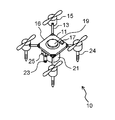
- FIG. 2 is a diagram showing the configuration of the flying object in the first embodiment.
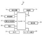
- FIG. 3 is a block diagram of the flying object in the first embodiment.
- FIG. 4 is a diagram illustrating a method for recognizing the position of another flying object using a light spot by laser light emitted from the flying object in the first embodiment.
- FIG. 5 is a flowchart showing a collision avoidance operation by the flying object in the first embodiment.
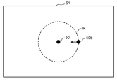
- FIG. 6A is a diagram illustrating an example of a captured image obtained by capturing with the camera of the flying object in the first embodiment.
- FIG. 6B is a diagram illustrating another example of a captured image obtained by capturing with the flying body camera according to the first exemplary embodiment.
- FIG. 1 is a diagram illustrating a configuration of an aerial video display system according to the present disclosure.
- the aerial video display system 100 includes a plurality of unmanned air vehicles 10 and a remote control device 60.
- the flying body 10 is an unmanned flying body that is automatically piloted, a so-called drone, and includes a light emitting element. As shown in FIG. 1, it is possible to display an arbitrary video by floating a plurality of flying objects 10 in the air and placing them in predetermined air positions to emit light. For example, in a large venue such as a stadium where sports competitions are held, several tens to several hundreds of flying objects 10 are suspended in the air at a height of 2 to 10 m, and the arrangement and light emission of the flying objects 10 are appropriately changed. Thus, various images can be displayed, and various light effects can be achieved.
- the flying object 10 of the present embodiment grasps the positional relationship with other flying objects 10 and autonomously performs avoidance actions when there is a possibility of a collision. Thereby, the collision between the flying object 10 and the other flying objects 10 is prevented.
- the details of the flying object 10 that performs such an autonomous collision avoidance operation will be described.
- FIG. 2 is an external view of the flying object 10 of the present embodiment.
- FIG. 3 is a block diagram showing a functional configuration of the flying vehicle 10 of the present embodiment.
- the flying object 10 includes a main body 11 and a propulsion device 15 that generates a propulsive force of the flying object 10.
- the propulsion device 15 is attached to the tip of the support portion 13 extending from each of the squares of the main body 11.
- a camera 21, a battery 25, and a laser light source 23 are attached to the lower side of the main body 11.
- An inertia measuring device 17 and a positioning device 19 are attached to the upper side of the main body 11.
- a controller 16 and a communication device 20 are housed inside the main body 11.
- the propulsion device 15 includes a propeller and a motor that rotates the propeller.
- the flying object 10 includes four propulsion devices 15, but the number of propulsion devices is not limited to four, and may be five or more, for example.
- a light emitter 24 is attached to the lower portion of the propulsion unit 15.
- the light emitter 24 includes a plurality of light emitting elements that emit light of each color of R (red), G (green), and B (blue), and can emit light of various colors.
- the camera 21 includes an image sensor such as a CCD (Charge-Coupled Device) or a CMOS (Complementary Metal Oxide Semiconductor) image sensor, and shoots a subject to generate image data.
- the generated image data is transmitted to the controller 16.
- the camera 21 is attached to the lower side of the main body 11 of the flying object 10, and captures an image of the flying object 10 vertically below while the flying object 10 is flying.
- the laser light source 23 includes a laser light emitting element and irradiates a laser beam vertically below the flying object 10 in flight.
- the laser light may be visible light or invisible light as long as it is in a wavelength band that can be photographed by the camera 21.
- the inertial measurement device 17 includes an acceleration sensor and a gyro sensor, and measures the acceleration and angular velocity of the flying object 10. Based on the output from the inertial measurement device 17, the behavior and posture of the flying object 10 are controlled.
- the positioning device 19 receives a signal from a GPS (Global Positioning System) satellite and measures the current position of the flying object 10.
- GPS Global Positioning System
- the communication device 20 includes an electronic circuit for performing wireless communication with the remote control device 60, and receives commands related to flight control, light emission control, and the like from the remote control device 60.
- the battery 25 supplies a power supply voltage to each element of the flying object 10.
- the flying object 10 configured as described above is controlled by remote operation, moves to a predetermined position in the air, and causes the light emitter 24 to emit light. That is, the flying object 10 receives a command by wireless communication from the remote control device 60 placed on the ground, and performs flight control and light emission control according to the received command. Note that the flying object 10 may receive a command by optical communication. Alternatively, the flying object 10 may autonomously perform flight control and light emission control. In this case, the flying object 10 is programmed in advance so as to move along a predetermined flight path and cause the light emitter 24 to emit light in a predetermined light emission pattern.
- FIG. 4 is a diagram illustrating a method for recognizing the position of another flying object using a light spot by laser light emitted from the flying object in the first embodiment.
- an arbitrary flying object 10 irradiates a laser beam Lz vertically below the flying object 10 with a laser light source 23 and images a region S below the flying object 10 with a camera 21.
- the flying object 10 may collide with another flying object 10b based on the positional relationship between the light spot 50 by its own laser beam Lz included in the captured image and the light spot 50b by the laser beam Lzb by the other flying object 10b. Judging. When there is a possibility of collision, the flying object 10 performs an operation for avoiding the collision.
- FIG. 5 is a flowchart showing the collision avoidance operation by the flying object in the first embodiment.
- the collision avoidance operation of the flying object 10 will be described in detail with reference to the flowchart of FIG.
- the flying object 10 irradiates the laser beam Lz from the laser light source 23 toward the vertically lower side of the flying object 10 while flying in the air.
- the flying object 10 captures the area S below the flying object 10 with the camera 21.
- the controller 16 of the flying object 10 analyzes the captured image and extracts a light spot by the laser beam.
- FIGS. 6A and 6B are diagrams illustrating an example of a photographed image obtained by photographing the vertically lower part of the flying object 10 with the camera 21 of the flying object 10.
- the controller 16 determines that the light spot at the center of the captured image is a light spot by the laser light of the own device, and determines that the other light spot is a light spot by the laser light from the other flying object 10b.
- two light spots 50 and 50b are detected in the photographed image S1
- the controller 16 determines that the light spot 50 at the center of the photographed image S1 is the own light spot.
- another light spot 50b is a light spot by another flying body 10b.
- the controller 16 determines the possibility of a collision between the flying object 10 and another flying object 10b based on the positional relationship of the light spot. To do. Specifically, the controller 16 sets a range having a radius of a predetermined distance centered on the position of the light spot 50 of the own device as the monitoring region R, and a light spot other than the own light spot 50 in the monitoring region R It is determined whether 50b has entered.
- the process proceeds to S14, and the light spot 50b of the other flying object 10b does not enter the monitoring area R. If this is the case (NO), the collision avoidance operation is terminated.
- the controller 16 determines a path for avoiding a collision based on the movement of the light spot 50b of the other flying object 10b, specifically, the position, the speed, and the moving direction.
- the controller 16 controls the propulsion device 15 to move along the determined route. This avoids collisions. For example, as shown in FIG. 6A, when the light spot 50b from the other flying object 10b enters the monitoring region R, the controller 16 is orthogonal to the moving direction of the other flying object 10b as shown in FIG. 6B. The collision is avoided by moving the aircraft in the direction to go.
- FIG. For example, laser light may be irradiated while blinking at high speed according to identification information. In this case, the light spot also blinks at high speed according to the identification information. Therefore, the controller 16 can read the identification information from the light spot in the moving image that is a photographed image taken by the camera 21, can recognize the light spot of the own device, and can accurately recognize the position of the own device. It is also possible to accurately identify other flying objects 10 flying around the aircraft.
- the positional relationship between the own aircraft and the other flying object 10b is grasped, and there is a possibility of a collision. Operates to avoid collisions when it is determined.
- the flying object 10 of the present embodiment is a flying object capable of flying in the air, and a propulsion device 15 (an example of a propulsion unit) that generates a propulsive force for flying in the air;
- a camera 21 an example of an imaging unit) that captures a vertically lower part of the flying object 10 during flight; and
- a controller 16 that controls the operation of the propulsion unit; Is provided.
- the controller 16 analyzes the captured image, extracts a light spot by laser light, specifies a positional relationship with another flying object based on the extracted light spot, and collides with another flying body based on the specified positional relationship. Perform avoidance action.
- the flying object 10 grasps the other flying objects 10 existing around the aircraft by observing the light spot 50 by the laser light emitted by the flying object 10, and determines that there is a possibility of a collision. When it does, it works to avoid collisions. Thereby, the autonomous collision avoidance operation
- movement of the flying body 10 is realizable. According to this, it is not necessary to perform communication between the flying bodies 10, and a communication device such as a wireless communication device is not required.
- the first embodiment has been described as an example of the technology disclosed herein.
- the technology in the present disclosure is not limited to this, and can also be applied to an embodiment in which changes, replacements, additions, omissions, and the like are appropriately performed.
- This disclosure can autonomously avoid a collision and is useful for a flying object flying in the air.
Landscapes
- Engineering & Computer Science (AREA)
- Physics & Mathematics (AREA)
- General Physics & Mathematics (AREA)
- Aviation & Aerospace Engineering (AREA)
- Remote Sensing (AREA)
- Radar, Positioning & Navigation (AREA)
- Multimedia (AREA)
- Theoretical Computer Science (AREA)
- Automation & Control Theory (AREA)
- Mechanical Engineering (AREA)
- Computer Networks & Wireless Communication (AREA)
- Control Of Position, Course, Altitude, Or Attitude Of Moving Bodies (AREA)
Abstract
L'invention concerne un corps volant qui est capable de voler dans l'air et qui comprend : une unité de propulsion qui génère une force de propulsion pour voler dans l'air ; une source de lumière laser qui émet une lumière laser ; une unité d'imagerie qui image verticalement au-dessous du corps volant et génère une image capturée, pendant le vol ; et une unité de commande qui commande le fonctionnement de l'unité de propulsion. L'unité de commande : analyse l'image capturée ; extrait un point lumineux à l'aide d'une lumière laser ; spécifie des relations de position par rapport à d'autres corps volants, sur la base du point lumineux extrait ; et exécute une opération d'évitement de collision par rapport à d'autres corps volants, sur la base des relations de position spécifiées.
Priority Applications (2)
| Application Number | Priority Date | Filing Date | Title |
|---|---|---|---|
| JP2017504592A JP6371988B2 (ja) | 2015-03-12 | 2016-02-10 | 飛行体 |
| US15/699,410 US10304345B2 (en) | 2015-03-12 | 2017-09-08 | Unmanned aerial vehicle |
Applications Claiming Priority (2)
| Application Number | Priority Date | Filing Date | Title |
|---|---|---|---|
| JP2015-050023 | 2015-03-12 | ||
| JP2015050023 | 2015-03-12 |
Related Child Applications (1)
| Application Number | Title | Priority Date | Filing Date |
|---|---|---|---|
| US15/699,410 Continuation US10304345B2 (en) | 2015-03-12 | 2017-09-08 | Unmanned aerial vehicle |
Publications (1)
| Publication Number | Publication Date |
|---|---|
| WO2016143256A1 true WO2016143256A1 (fr) | 2016-09-15 |
Family
ID=56879437
Family Applications (1)
| Application Number | Title | Priority Date | Filing Date |
|---|---|---|---|
| PCT/JP2016/000684 WO2016143256A1 (fr) | 2015-03-12 | 2016-02-10 | Corps volant |
Country Status (3)
| Country | Link |
|---|---|
| US (1) | US10304345B2 (fr) |
| JP (1) | JP6371988B2 (fr) |
| WO (1) | WO2016143256A1 (fr) |
Cited By (11)
| Publication number | Priority date | Publication date | Assignee | Title |
|---|---|---|---|---|
| CN106896828A (zh) * | 2017-04-18 | 2017-06-27 | 厦门领夏智能科技有限公司 | 一种无人机自动无线充电方法及系统 |
| JP2018084955A (ja) * | 2016-11-24 | 2018-05-31 | 株式会社小糸製作所 | 無人航空機 |
| KR20180119455A (ko) * | 2017-04-25 | 2018-11-02 | 육상조 | 광고용 드론. |
| JP2019046117A (ja) * | 2017-08-31 | 2019-03-22 | サクサ株式会社 | 無人飛行装置 |
| CN106950989B (zh) * | 2017-04-18 | 2019-09-10 | 厦门领夏智能科技有限公司 | 一种无人机定点定位方法及系统 |
| WO2019189370A1 (fr) * | 2018-03-30 | 2019-10-03 | 株式会社ニコン | Système d'imagerie et corps mobile |
| JP2019192111A (ja) * | 2018-04-27 | 2019-10-31 | エスゼット ディージェイアイ テクノロジー カンパニー リミテッドSz Dji Technology Co.,Ltd | 情報処理装置、情報提示指示方法、プログラム、及び記録媒体 |
| WO2019216189A1 (fr) * | 2018-05-08 | 2019-11-14 | 株式会社eロボティクス福島 | Groupe de drones et procédé de mesure d'environnement atmosphérique |
| WO2020170502A1 (fr) * | 2019-02-19 | 2020-08-27 | 日本電気株式会社 | Robot, procédé de fonctionnement du robot et support non transitoire lisible par ordinateur |
| KR102299840B1 (ko) * | 2021-03-31 | 2021-09-10 | 주식회사 드론고 | 홀로그램 재현 가능한 공연용 드론 |
| KR102347339B1 (ko) * | 2021-06-10 | 2022-01-06 | 주식회사 코코드론 | 드론을 이용한 입체영상제공방법 |
Families Citing this family (3)
| Publication number | Priority date | Publication date | Assignee | Title |
|---|---|---|---|---|
| US9807996B1 (en) * | 2016-05-28 | 2017-11-07 | Simon Siu-Chi Yu | Bug eater |
| US11754708B1 (en) * | 2018-12-10 | 2023-09-12 | Amazon Technologies, Inc. | Object detection using propeller noise |
| US20220245380A1 (en) * | 2021-02-04 | 2022-08-04 | Skyway Technologies Corp. | Light identification system for unmanned aerial vehicles |
Citations (4)
| Publication number | Priority date | Publication date | Assignee | Title |
|---|---|---|---|---|
| JP2009223632A (ja) * | 2008-03-17 | 2009-10-01 | Hitachi Ltd | 自律移動装置、及び、自律移動装置システム |
| JP2011183824A (ja) * | 2010-03-04 | 2011-09-22 | Chugoku Electric Power Co Inc:The | 空中撮影システム |
| JP2014119828A (ja) * | 2012-12-13 | 2014-06-30 | Secom Co Ltd | 自律飛行ロボット |
| JP2015191254A (ja) * | 2014-03-27 | 2015-11-02 | 日本電気株式会社 | 無人航空機、無人航空機の制御方法、および、管制システム |
Family Cites Families (19)
| Publication number | Priority date | Publication date | Assignee | Title |
|---|---|---|---|---|
| JPH09325245A (ja) | 1996-05-31 | 1997-12-16 | Kyocera Corp | 光通信用モジュール |
| JPH11139396A (ja) | 1997-11-10 | 1999-05-25 | Makoto Toyama | 編隊飛行制御装置 |
| JP2000159194A (ja) * | 1998-11-30 | 2000-06-13 | Mitsubishi Agricult Mach Co Ltd | 無人ヘリコプタ |
| JP2002006784A (ja) | 2000-06-20 | 2002-01-11 | Mitsubishi Electric Corp | 浮遊型ロボット |
| JP2002082720A (ja) | 2000-06-29 | 2002-03-22 | Inst Of Physical & Chemical Res | 移動体の目標位置教示方法、移動制御方法、光誘導方法および光誘導システム |
| US6629028B2 (en) | 2000-06-29 | 2003-09-30 | Riken | Method and system of optical guidance of mobile body |
| US6665063B2 (en) * | 2001-09-04 | 2003-12-16 | Rosemount Aerospace Inc. | Distributed laser obstacle awareness system |
| JP4057344B2 (ja) | 2002-05-27 | 2008-03-05 | シャープ株式会社 | 情報提示装置および情報提示システム |
| JP4116476B2 (ja) | 2003-03-07 | 2008-07-09 | ヤマハ発動機株式会社 | 無人ヘリコプタの表示装置及びその使用方法 |
| JP2006285635A (ja) | 2005-03-31 | 2006-10-19 | Toshiba Corp | 表示案内装置、ロボットシステム及びロボットシステムにおける表示案内方法 |
| JP5690539B2 (ja) | 2010-09-28 | 2015-03-25 | 株式会社トプコン | 自動離着陸システム |
| EP2511781A1 (fr) * | 2011-04-14 | 2012-10-17 | Hexagon Technology Center GmbH | Système et procédé de commande d'un aéronef sans pilote |
| FR2990290B1 (fr) * | 2012-05-02 | 2015-04-03 | Sagem Defense Securite | Procede d'evitement d'un aeronef et drone equipe d'un systeme mettant en oeuvre ce procede |
| US9037392B2 (en) * | 2012-05-30 | 2015-05-19 | Honeywell International Inc. | Airport surface collision-avoidance system (ASCAS) |
| US9417325B1 (en) * | 2014-01-10 | 2016-08-16 | Google Inc. | Interface for accessing radar data |
| US10078136B2 (en) * | 2014-03-25 | 2018-09-18 | Amazon Technologies, Inc. | Sense and avoid for automated mobile vehicles |
| US9812021B2 (en) * | 2014-06-25 | 2017-11-07 | Amazon Technologies, Inc. | Object avoidance for automated aerial vehicles |
| US11968022B2 (en) * | 2014-08-18 | 2024-04-23 | Sunlight Aerospace Inc. | Distributed airborne wireless communication services |
| CN104309803B (zh) * | 2014-10-27 | 2017-07-21 | 广州极飞科技有限公司 | 旋翼飞行器自动降落系统及方法 |
-
2016
- 2016-02-10 WO PCT/JP2016/000684 patent/WO2016143256A1/fr active Application Filing
- 2016-02-10 JP JP2017504592A patent/JP6371988B2/ja not_active Expired - Fee Related
-
2017
- 2017-09-08 US US15/699,410 patent/US10304345B2/en active Active
Patent Citations (4)
| Publication number | Priority date | Publication date | Assignee | Title |
|---|---|---|---|---|
| JP2009223632A (ja) * | 2008-03-17 | 2009-10-01 | Hitachi Ltd | 自律移動装置、及び、自律移動装置システム |
| JP2011183824A (ja) * | 2010-03-04 | 2011-09-22 | Chugoku Electric Power Co Inc:The | 空中撮影システム |
| JP2014119828A (ja) * | 2012-12-13 | 2014-06-30 | Secom Co Ltd | 自律飛行ロボット |
| JP2015191254A (ja) * | 2014-03-27 | 2015-11-02 | 日本電気株式会社 | 無人航空機、無人航空機の制御方法、および、管制システム |
Cited By (13)
| Publication number | Priority date | Publication date | Assignee | Title |
|---|---|---|---|---|
| JP2018084955A (ja) * | 2016-11-24 | 2018-05-31 | 株式会社小糸製作所 | 無人航空機 |
| CN106950989B (zh) * | 2017-04-18 | 2019-09-10 | 厦门领夏智能科技有限公司 | 一种无人机定点定位方法及系统 |
| CN106896828A (zh) * | 2017-04-18 | 2017-06-27 | 厦门领夏智能科技有限公司 | 一种无人机自动无线充电方法及系统 |
| CN106896828B (zh) * | 2017-04-18 | 2019-09-06 | 厦门领夏智能科技有限公司 | 一种无人机自动无线充电方法及系统 |
| KR20180119455A (ko) * | 2017-04-25 | 2018-11-02 | 육상조 | 광고용 드론. |
| KR102019335B1 (ko) * | 2017-04-25 | 2019-09-09 | 육상조 | 광고용 드론. |
| JP2019046117A (ja) * | 2017-08-31 | 2019-03-22 | サクサ株式会社 | 無人飛行装置 |
| WO2019189370A1 (fr) * | 2018-03-30 | 2019-10-03 | 株式会社ニコン | Système d'imagerie et corps mobile |
| JP2019192111A (ja) * | 2018-04-27 | 2019-10-31 | エスゼット ディージェイアイ テクノロジー カンパニー リミテッドSz Dji Technology Co.,Ltd | 情報処理装置、情報提示指示方法、プログラム、及び記録媒体 |
| WO2019216189A1 (fr) * | 2018-05-08 | 2019-11-14 | 株式会社eロボティクス福島 | Groupe de drones et procédé de mesure d'environnement atmosphérique |
| WO2020170502A1 (fr) * | 2019-02-19 | 2020-08-27 | 日本電気株式会社 | Robot, procédé de fonctionnement du robot et support non transitoire lisible par ordinateur |
| KR102299840B1 (ko) * | 2021-03-31 | 2021-09-10 | 주식회사 드론고 | 홀로그램 재현 가능한 공연용 드론 |
| KR102347339B1 (ko) * | 2021-06-10 | 2022-01-06 | 주식회사 코코드론 | 드론을 이용한 입체영상제공방법 |
Also Published As
| Publication number | Publication date |
|---|---|
| JPWO2016143256A1 (ja) | 2017-12-21 |
| US10304345B2 (en) | 2019-05-28 |
| US20170372625A1 (en) | 2017-12-28 |
| JP6371988B2 (ja) | 2018-08-15 |
Similar Documents
| Publication | Publication Date | Title |
|---|---|---|
| JP6371988B2 (ja) | 飛行体 | |
| JP6405048B2 (ja) | 回転翼機及びその自動着陸システム及び方法 | |
| US10308348B2 (en) | Unmanned moving vehicle piloting method and unmanned moving vehicle watching device | |
| JP6601554B2 (ja) | 無人航空機、無人航空機制御システム、飛行制御方法およびコンピュータプログラム | |
| US10061328B2 (en) | Autonomous landing and control | |
| JP6379575B2 (ja) | 無人航空機、無人航空機の制御方法、および、管制システム | |
| US11100662B2 (en) | Image processing apparatus, ranging apparatus and processing apparatus | |
| US10351240B1 (en) | Methods and systems for cooperative operation and configuration of aerially-mobile devices | |
| CN107085433B (zh) | 发光控制装置、无人飞行器、以及发光控制方法 | |
| WO2016179802A1 (fr) | Appareils et procédés de reconnaissance ou de détection d'un obstacle | |
| WO2018137133A1 (fr) | Systèmes et procédés de commande radar sur des plateformes mobiles sans pilote | |
| KR101914179B1 (ko) | 무인비행체의 충전위치 탐지 장치 | |
| JP2023113608A (ja) | 飛行体 | |
| WO2016143255A1 (fr) | Corps volant et système d'affichage de vidéo aérienne | |
| JP2023099565A (ja) | 飛行体、点検方法及び点検システム | |
| Moldagalieva et al. | Virtual omnidirectional perception for downwash prediction within a team of nano multirotors flying in close proximity | |
| WO2016143257A1 (fr) | Corps volant | |
| US20230109408A1 (en) | Information processing device, method, computer program, and communication system | |
| JP2019032797A (ja) | 移動体、制御方法及び制御プログラム | |
| JP2017132377A (ja) | 飛行装置 | |
| KR102571330B1 (ko) | 피사체 추적 촬영제어장치, 드론 및 그것의 동작 방법 | |
| US11722791B2 (en) | Ranging device, image processing device and method | |
| JP7478600B2 (ja) | 異常通知システム | |
| Singhata | Autonomous Mobile Robot Using Vision System and ESP8266 Node MCU Board | |
| KR20180025655A (ko) | 무인 비행체 |
Legal Events
| Date | Code | Title | Description |
|---|---|---|---|
| 121 | Ep: the epo has been informed by wipo that ep was designated in this application |
Ref document number: 16761235 Country of ref document: EP Kind code of ref document: A1 |
|
| ENP | Entry into the national phase |
Ref document number: 2017504592 Country of ref document: JP Kind code of ref document: A |
|
| NENP | Non-entry into the national phase |
Ref country code: DE |
|
| 122 | Ep: pct application non-entry in european phase |
Ref document number: 16761235 Country of ref document: EP Kind code of ref document: A1 |