WO2016139962A1 - クランプ装置 - Google Patents
クランプ装置 Download PDFInfo
- Publication number
- WO2016139962A1 WO2016139962A1 PCT/JP2016/050109 JP2016050109W WO2016139962A1 WO 2016139962 A1 WO2016139962 A1 WO 2016139962A1 JP 2016050109 W JP2016050109 W JP 2016050109W WO 2016139962 A1 WO2016139962 A1 WO 2016139962A1
- Authority
- WO
- WIPO (PCT)
- Prior art keywords
- proximity sensor
- clamp
- clamping device
- state
- clamping
- Prior art date
- Legal status (The legal status is an assumption and is not a legal conclusion. Google has not performed a legal analysis and makes no representation as to the accuracy of the status listed.)
- Ceased
Links
Images


Classifications
-
- B—PERFORMING OPERATIONS; TRANSPORTING
- B25—HAND TOOLS; PORTABLE POWER-DRIVEN TOOLS; MANIPULATORS
- B25B—TOOLS OR BENCH DEVICES NOT OTHERWISE PROVIDED FOR, FOR FASTENING, CONNECTING, DISENGAGING, OR HOLDING
- B25B5/00—Clamps
- B25B5/06—Arrangements for positively actuating jaws
- B25B5/08—Arrangements for positively actuating jaws using cams
- B25B5/087—Arrangements for positively actuating jaws using cams actuated by a hydraulic or pneumatic piston
-
- B—PERFORMING OPERATIONS; TRANSPORTING
- B23—MACHINE TOOLS; METAL-WORKING NOT OTHERWISE PROVIDED FOR
- B23Q—DETAILS, COMPONENTS, OR ACCESSORIES FOR MACHINE TOOLS, e.g. ARRANGEMENTS FOR COPYING OR CONTROLLING; MACHINE TOOLS IN GENERAL CHARACTERISED BY THE CONSTRUCTION OF PARTICULAR DETAILS OR COMPONENTS; COMBINATIONS OR ASSOCIATIONS OF METAL-WORKING MACHINES, NOT DIRECTED TO A PARTICULAR RESULT
- B23Q3/00—Devices holding, supporting, or positioning work or tools, of a kind normally removable from the machine
- B23Q3/02—Devices holding, supporting, or positioning work or tools, of a kind normally removable from the machine for mounting on a work-table, tool-slide, or analogous part
- B23Q3/06—Work-clamping means
-
- B—PERFORMING OPERATIONS; TRANSPORTING
- B23—MACHINE TOOLS; METAL-WORKING NOT OTHERWISE PROVIDED FOR
- B23K—SOLDERING OR UNSOLDERING; WELDING; CLADDING OR PLATING BY SOLDERING OR WELDING; CUTTING BY APPLYING HEAT LOCALLY, e.g. FLAME CUTTING; WORKING BY LASER BEAM
- B23K37/00—Auxiliary devices or processes, not specially adapted for a procedure covered by only one of the other main groups of this subclass
- B23K37/04—Auxiliary devices or processes, not specially adapted for a procedure covered by only one of the other main groups of this subclass for holding or positioning work
- B23K37/0426—Fixtures for other work
- B23K37/0435—Clamps
-
- B—PERFORMING OPERATIONS; TRANSPORTING
- B23—MACHINE TOOLS; METAL-WORKING NOT OTHERWISE PROVIDED FOR
- B23Q—DETAILS, COMPONENTS, OR ACCESSORIES FOR MACHINE TOOLS, e.g. ARRANGEMENTS FOR COPYING OR CONTROLLING; MACHINE TOOLS IN GENERAL CHARACTERISED BY THE CONSTRUCTION OF PARTICULAR DETAILS OR COMPONENTS; COMBINATIONS OR ASSOCIATIONS OF METAL-WORKING MACHINES, NOT DIRECTED TO A PARTICULAR RESULT
- B23Q17/00—Arrangements for observing, indicating or measuring on machine tools
- B23Q17/002—Arrangements for observing, indicating or measuring on machine tools for indicating or measuring the holding action of work or tool holders
- B23Q17/003—Arrangements for observing, indicating or measuring on machine tools for indicating or measuring the holding action of work or tool holders by measuring a position
-
- B—PERFORMING OPERATIONS; TRANSPORTING
- B23—MACHINE TOOLS; METAL-WORKING NOT OTHERWISE PROVIDED FOR
- B23Q—DETAILS, COMPONENTS, OR ACCESSORIES FOR MACHINE TOOLS, e.g. ARRANGEMENTS FOR COPYING OR CONTROLLING; MACHINE TOOLS IN GENERAL CHARACTERISED BY THE CONSTRUCTION OF PARTICULAR DETAILS OR COMPONENTS; COMBINATIONS OR ASSOCIATIONS OF METAL-WORKING MACHINES, NOT DIRECTED TO A PARTICULAR RESULT
- B23Q3/00—Devices holding, supporting, or positioning work or tools, of a kind normally removable from the machine
- B23Q3/02—Devices holding, supporting, or positioning work or tools, of a kind normally removable from the machine for mounting on a work-table, tool-slide, or analogous part
- B23Q3/06—Work-clamping means
- B23Q3/08—Work-clamping means other than mechanically-actuated
- B23Q3/082—Work-clamping means other than mechanically-actuated hydraulically actuated
-
- B—PERFORMING OPERATIONS; TRANSPORTING
- B25—HAND TOOLS; PORTABLE POWER-DRIVEN TOOLS; MANIPULATORS
- B25B—TOOLS OR BENCH DEVICES NOT OTHERWISE PROVIDED FOR, FOR FASTENING, CONNECTING, DISENGAGING, OR HOLDING
- B25B5/00—Clamps
- B25B5/02—Clamps with sliding jaws
-
- B—PERFORMING OPERATIONS; TRANSPORTING
- B25—HAND TOOLS; PORTABLE POWER-DRIVEN TOOLS; MANIPULATORS
- B25B—TOOLS OR BENCH DEVICES NOT OTHERWISE PROVIDED FOR, FOR FASTENING, CONNECTING, DISENGAGING, OR HOLDING
- B25B5/00—Clamps
- B25B5/04—Clamps with pivoted jaws
-
- B—PERFORMING OPERATIONS; TRANSPORTING
- B25—HAND TOOLS; PORTABLE POWER-DRIVEN TOOLS; MANIPULATORS
- B25B—TOOLS OR BENCH DEVICES NOT OTHERWISE PROVIDED FOR, FOR FASTENING, CONNECTING, DISENGAGING, OR HOLDING
- B25B5/00—Clamps
- B25B5/06—Arrangements for positively actuating jaws
- B25B5/061—Arrangements for positively actuating jaws with fluid drive
-
- B—PERFORMING OPERATIONS; TRANSPORTING
- B25—HAND TOOLS; PORTABLE POWER-DRIVEN TOOLS; MANIPULATORS
- B25B—TOOLS OR BENCH DEVICES NOT OTHERWISE PROVIDED FOR, FOR FASTENING, CONNECTING, DISENGAGING, OR HOLDING
- B25B5/00—Clamps
- B25B5/06—Arrangements for positively actuating jaws
- B25B5/12—Arrangements for positively actuating jaws using toggle links
-
- B—PERFORMING OPERATIONS; TRANSPORTING
- B25—HAND TOOLS; PORTABLE POWER-DRIVEN TOOLS; MANIPULATORS
- B25B—TOOLS OR BENCH DEVICES NOT OTHERWISE PROVIDED FOR, FOR FASTENING, CONNECTING, DISENGAGING, OR HOLDING
- B25B5/00—Clamps
- B25B5/06—Arrangements for positively actuating jaws
- B25B5/12—Arrangements for positively actuating jaws using toggle links
- B25B5/122—Arrangements for positively actuating jaws using toggle links with fluid drive
-
- B—PERFORMING OPERATIONS; TRANSPORTING
- B25—HAND TOOLS; PORTABLE POWER-DRIVEN TOOLS; MANIPULATORS
- B25B—TOOLS OR BENCH DEVICES NOT OTHERWISE PROVIDED FOR, FOR FASTENING, CONNECTING, DISENGAGING, OR HOLDING
- B25B5/00—Clamps
- B25B5/16—Details, e.g. jaws, jaw attachments
-
- F—MECHANICAL ENGINEERING; LIGHTING; HEATING; WEAPONS; BLASTING
- F15—FLUID-PRESSURE ACTUATORS; HYDRAULICS OR PNEUMATICS IN GENERAL
- F15B—SYSTEMS ACTING BY MEANS OF FLUIDS IN GENERAL; FLUID-PRESSURE ACTUATORS, e.g. SERVOMOTORS; DETAILS OF FLUID-PRESSURE SYSTEMS, NOT OTHERWISE PROVIDED FOR
- F15B15/00—Fluid-actuated devices for displacing a member from one position to another; Gearing associated therewith
- F15B15/02—Mechanical layout characterised by the means for converting the movement of the fluid-actuated element into movement of the finally-operated member
-
- F—MECHANICAL ENGINEERING; LIGHTING; HEATING; WEAPONS; BLASTING
- F15—FLUID-PRESSURE ACTUATORS; HYDRAULICS OR PNEUMATICS IN GENERAL
- F15B—SYSTEMS ACTING BY MEANS OF FLUIDS IN GENERAL; FLUID-PRESSURE ACTUATORS, e.g. SERVOMOTORS; DETAILS OF FLUID-PRESSURE SYSTEMS, NOT OTHERWISE PROVIDED FOR
- F15B15/00—Fluid-actuated devices for displacing a member from one position to another; Gearing associated therewith
- F15B15/02—Mechanical layout characterised by the means for converting the movement of the fluid-actuated element into movement of the finally-operated member
- F15B15/06—Mechanical layout characterised by the means for converting the movement of the fluid-actuated element into movement of the finally-operated member for mechanically converting rectilinear movement into non- rectilinear movement
-
- F—MECHANICAL ENGINEERING; LIGHTING; HEATING; WEAPONS; BLASTING
- F15—FLUID-PRESSURE ACTUATORS; HYDRAULICS OR PNEUMATICS IN GENERAL
- F15B—SYSTEMS ACTING BY MEANS OF FLUIDS IN GENERAL; FLUID-PRESSURE ACTUATORS, e.g. SERVOMOTORS; DETAILS OF FLUID-PRESSURE SYSTEMS, NOT OTHERWISE PROVIDED FOR
- F15B15/00—Fluid-actuated devices for displacing a member from one position to another; Gearing associated therewith
- F15B15/20—Other details, e.g. assembly with regulating devices
- F15B15/28—Means for indicating the position, e.g. end of stroke
Definitions
- the present invention relates to a clamping device that clamps a workpiece by a rotating clamp arm.
- a clamping device is used to clamp the component.
- the workpiece can be clamped by displacing the piston of the cylinder portion in the axial direction under the action of fluid pressure and rotating the clamp arm via a toggle link mechanism connected to the piston rod. Switching between the clamped state and the unclamped state in which the clamped state is released (see, for example, JP-A-2001-113468).
- a detection unit is connected to a knuckle block connected to a piston rod, and the detection unit is detected by two proximity sensors provided on the side of the clamp body.
- the clamped state and the unclamped state are detected.
- the present invention has been made in consideration of the above-described problems, and has a simple configuration and can easily and reliably determine whether or not a predetermined clamping force is reliably generated on a workpiece.
- the purpose is to provide.
- a clamping device includes a clamping body, a driving member that linearly moves in a predetermined direction in the clamping body, and a linear movement of the driving member in the clamping arm.
- a detecting mechanism for detecting whether or not the clamp mechanism is in a clamped state based on an output of the detecting means. Includes a detected body that is displaced in a predetermined direction in accordance with a linear motion of the driving member, and a first proximity sensor that detects a position of the detected body, and the detected body is a portion facing the first proximity sensor.
- the determination unit determines whether or not the clamp state is established based on a comparison between the output signal of the first proximity sensor and a predetermined clamp threshold value. Further, and judging whether or not the clamping force generating state based on the comparison of the output signal and the predetermined clamping force generating threshold of the first proximity sensor.
- the linear motion of the drive member that is output to generate the clamping force on the workpiece is changed with the change in the distance between the first inclined surface and the first proximity sensor. Therefore, it is possible to easily and reliably determine whether or not the clamping force is generated (a state where a predetermined clamping force is generated on the workpiece) in the clamping state of the workpiece.
- the detection unit includes a second proximity sensor that is spaced apart from the first proximity sensor along a predetermined direction, and the detection target is provided at a position facing the second proximity sensor. It has a 2nd inclined surface which inclines with respect to a direction, and a judgment part is good to judge whether it is in an unclamped state based on comparison with an output signal of the 2nd proximity sensor, and a predetermined unclamp threshold.
- the unclamped state can be easily and reliably determined.
- a setting operation unit that can be operated by the user, and a clamp threshold is set based on an output signal of the first proximity sensor when the setting operation unit is first operated.
- a threshold setting unit that sets an unclamping threshold based on an output signal of the second proximity sensor when the second operation is performed.
- the clamping threshold value and the unclamping threshold value can be easily set according to the shape and size of the workpiece to be clamped.
- the threshold setting unit may set the clamping force generation threshold based on the output signal of the first proximity sensor when the setting operation unit is operated for the third time.
- the clamping force generation threshold can be easily set without changing the position of the first proximity sensor.
- the above clamping device it is disposed so as to be visible from the outside, and is lit when the determination unit determines that it is in a clamped state, and is disposed so as to be visible from the outside and unclamped by the determination unit. And an unclamping lamp that is turned on when it is determined to be in a state.
- the user can easily confirm the clamped state and the unclamped state of the workpiece.
- the above clamping device may be provided with a clamping force generating lamp that is disposed so as to be visible from the outside and that is turned on when the determination unit determines that the clamping force is generated.
- the user can easily confirm the state of occurrence of the clamping force of the workpiece.
- a speed calculation unit that calculates the rotation speed of the clamp arm based on the output signal of the first proximity sensor and the output signal of the second proximity sensor, and the rotation speed calculated by the speed calculation unit is predetermined. It is good to provide a speed judgment part which judges whether it is below a speed threshold of.
- the rotation speed of the clamp arm is excessively increased, and it is possible to suppress damage to the workpiece and the component parts such as the link mechanism of the clamp device.
- the above clamping device may be provided with a speed light that is disposed so as to be visible from the outside and that is turned on when the speed determination unit determines that the rotational speed exceeds the speed threshold.
- the user can easily confirm whether or not the rotation speed of the clamp arm is equal to or less than the speed threshold value.
- the detected object may be made of a metal material
- the first proximity sensor and the second proximity sensor may be inductive proximity sensors.
- the first The proximity sensor and the second proximity sensor can be operated more stably.
- the above clamping device further includes a cylinder tube and a piston that reciprocates in the cylinder tube along the axial direction under the action of fluid pressure, and the drive member is a piston rod connected to the piston,
- the detected body may be a knuckle joint that connects the piston rod and the link mechanism to each other.
- the first proximity sensor and the second proximity sensor may be disposed in a clamp body configured to include a metal material.
- the clamp device can be reduced in size as compared with the case where the first proximity sensor and the second proximity sensor are disposed outside the clamp body. Further, since the clamp body functions as a magnetic shield, it is possible to make it less susceptible to the influence of a DC magnetic field generated during welding.
- the linear motion of the drive member output to generate a clamping force on the workpiece is detected as a change in the distance between the first inclined surface and the first proximity sensor. Therefore, it is possible to easily and reliably determine whether or not the workpiece is in a clamping force generation state (a state in which a predetermined clamping force is generated in the workpiece).
- FIG. 1 is a front view of a clamp device according to an embodiment of the present invention.
- FIG. 2 is a partially exploded perspective view of the clamp device shown in FIG.
- FIG. 3 is a longitudinal sectional view showing a clamping state of the clamping device shown in FIG.
- FIG. 4 is a block diagram of the clamping device shown in FIG.
- FIG. 5 is a longitudinal sectional view showing an unclamped state of the clamping device shown in FIG. 1.
- FIG. 6 is a graph showing the relationship between the distance between the second inclined surface and the detection coil and the detected resonance impedance.
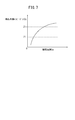
- FIG. 7 is a graph showing the relationship between the separation distance between the first inclined surface and the detection coil and the detected resonance impedance.
- a clamp device 10 includes a drive mechanism 12, a clamp body 14 coupled to the drive mechanism 12, and a link mechanism disposed in the clamp body 14. 16, a clamp arm 17 that rotates through the link mechanism 16 under the action of the drive mechanism 12, a detection mechanism (detection means) 18 that detects the rotation state of the clamp arm 17, and a control unit 20. ing.
- the drive mechanism 12 is configured as a fluid pressure cylinder, a cylinder tube 22 configured in a flat cylindrical shape, an end block 24 that closes an opening on one end side (in the direction of arrow A) of the cylinder tube 22, and the cylinder tube 22.
- a piston 26 that is displaceably disposed along the axial direction, a rod cover 28 that closes an opening on the other end side (in the direction of arrow B) of the cylinder tube 22, and a piston rod 30 ( Drive member).
- the cylinder tube 22 is not limited to a flat cylindrical shape, and may have any shape such as a true cylindrical shape or an elliptical cylindrical shape.
- the cylinder tube 22 includes a first port 34 communicating with the first cylinder chamber 32 formed between the end block 24 and the piston 26, and a second cylinder chamber 36 formed between the piston 26 and the rod cover 28.
- a second port 38 that communicates is formed.
- the first port 34 and the second port 38 are connected to a tube (not shown) for supplying and discharging a compressed fluid (driving fluid) for reciprocating the piston 26.
- the end block 24, the cylinder tube 22, and the rod cover 28 are integrally connected by a plurality of fastening bolts 40.
- a damper 44 for buffering the impact and collision sound of the piston 26 is mounted at a substantially central portion of the end block 24.
- An annular piston packing 48 is attached to the outer peripheral surface of the piston 26 via a groove. Further, one end side of the piston rod 30 is fixed to the center of the piston 26.
- a rod hole 50 through which the piston rod 30 is inserted is formed at the center of the rod cover 28.
- An annular rod packing 52 and an annular dust seal 54 are mounted on the wall surface constituting the rod hole 50 through grooves.
- the clamp body 14 is connected to the other end side of the rod cover 28 and includes, for example, a metal material such as iron, stainless steel, or aluminum.
- the clamp body 14 is provided with a bracket 56 for attaching the clamp device 10 to a fixing member (not shown).
- the clamp body 14 includes a frame portion 58 opened on both sides, and a pair of covers fastened to the frame portion 58 by a plurality of screw members 59 so as to close the opening of the frame portion 58. Part 60.
- a chamber in which the other end side of the piston rod 30 and the link mechanism 16 can be disposed is formed in the clamp body 14.
- the link mechanism 16 is connected to the other end of the piston rod 30 via a knuckle joint 62.
- a groove portion 64 having a substantially T-shaped cross section extending in a direction orthogonal to the axial direction of the piston rod 30 is formed in a portion of the knuckle joint 62 that faces the piston rod 30.
- the other end of the piston rod 30 is attached to the groove 64.
- the knuckle joint 62 is formed with a hole extending along a direction orthogonal to the cover 60 (direction orthogonal to the paper surface of FIG. 3).
- a knuckle pin 66 is inserted through the hole.
- the knuckle joint 62 is made of a metal material that causes eddy current loss such as iron. As shown in FIG. 3, the first inclined surface 98 and the second inclined surface 100 are formed in a portion that is directed to the opposite side (left side in FIG. 3) of the knuckle joint 62 in the workpiece clamping state. Has been.
- the first inclined surface 98 and the second inclined surface 100 are gradually moved from the central portion of the knuckle joint 62 toward the side opposite to the piston rod 30 (arrow B direction) and the piston rod 30 side (arrow A direction). It is formed as an inclined surface that inclines.
- the positions of the first inclined surface 98 and the second inclined surface 100 are detected by a first proximity sensor 102a and a second proximity sensor 102b described later. That is, the knuckle joint 62 functions as an object to be detected that is detected by the first proximity sensor 102a and the second proximity sensor 102b.
- the link mechanism 16 converts the reciprocating motion (linear motion) of the piston 26 into a rotational motion of the rotational shaft 82 described later.
- the link mechanism 16 is provided at a knuckle joint 62 via a knuckle pin 66 so as to be rotatable, and at a first link part 68 via a first pin 70.
- the second link portion 72 and a support lever 76 that is rotatably provided on the second link portion 72 via a second pin 74 are provided.
- first link portion 68 a hole portion through which the knuckle pin 66 is inserted and a hole portion through which the first pin 70 is inserted are formed apart from each other.
- second link portion 72 a hole portion through which the first pin 70 is inserted and a hole portion through which the second pin 74 is inserted are formed apart from each other.
- Rotating shaft 82 supported by a bearing 80 inserted through hole 78 of cover 60 is fixed to support lever 76.
- the first pin 70, the second pin 74, and the rotation shaft 82 are disposed in parallel to the knuckle pin 66.
- An arm support portion 86 to which the clamp arm 17 is attached is fixed to the end portion of the rotation shaft 82. That is, the rotation shaft 82 rotates integrally with the clamp arm 17.
- the linear motion of the piston rod 30 is transmitted to the knuckle joint 62, the first link portion 68, the second link portion 72, and the support lever 76, and the support lever 76 is rotationally displaced together with the rotational shaft 82 by a predetermined angle.
- the clamp arm 17 connected to the rotational shaft 82 via the arm support portion 86 rotates.
- a guide roller 88 is provided in the vicinity of the link mechanism 16.
- the guide roller 88 is rotatably provided via a plurality of rolling elements 94 with respect to the pin member 92 inserted through the hole 90 of the cover 60. And the guide roller 88 rotates when the predetermined action surface 96 of the 2nd link part 72 contacts under the rotation effect
- the working surface 96 of the second link portion 72 is formed so that the contact angle ⁇ between the working surface 96 and the guide roller 88 is constant while contacting the guide roller 88.
- the contact angle ⁇ is an angle formed by a line segment L1 perpendicular to the rotation axis of the guide roller 88 in a state parallel to the axis of the piston rod 30 and a tangent L2 on the working surface 96 of the guide roller 88.
- the effective range in which a predetermined clamping force can be generated on the workpiece (the width of the rotation angle of the clamp arm 17) can be made relatively wide. Therefore, even when the dimensional variation of the workpiece is relatively large, a predetermined clamping force can be generated on the workpiece without increasing the pressure of the compressed fluid for driving the fluid pressure cylinder more than necessary. .
- the detection mechanism 18 includes a knuckle joint (detected body) 62 that undergoes stroke displacement together with the piston rod 30, and a first proximity sensor 102a and a second proximity sensor 102b.
- the first proximity sensor 102a and the second proximity sensor 102b are arranged in the clamp body 14 at a predetermined interval along the direction in which the piston rod 30 is displaced in the stroke (arrow AB direction).
- the first proximity sensor 102a is disposed on the other end side (arrow B direction) of the piston rod 30 in the clamp body 14, and detects the position of the first inclined surface 98 of the knuckle joint 62.
- the second proximity sensor 102 b is disposed on one end side (in the direction of arrow A) of the piston rod 30 in the clamp body 14 and detects the position of the second inclined surface 100 of the knuckle joint 62.
- the 2nd proximity sensor 102b has the same component as the 1st proximity sensor 102a, in the following description, the same referential mark is attached
- the reference numerals of the constituent elements of the first proximity sensor 102a are given a suffix a
- the reference numerals of the constituent elements of the second proximity sensor 102b are given a suffix b to distinguish them from each other.
- the first proximity sensor 102a is configured as an inductive proximity sensor, and includes a detection coil 104a and an oscillation circuit unit 106a electrically connected to the detection coil 104a. And a detection circuit unit 108a electrically connected to the oscillation circuit unit 106a.
- the detection coil 104a is disposed such that its coil surface is close to and faces the first inclined surface 98 of the knuckle joint 62.
- the oscillation circuit unit 106a oscillates and drives the detection coil 104a at a predetermined oscillation frequency.
- the detection circuit unit 108a detects the resonance impedance based on the output signal of the oscillation circuit unit 106a. That is, the first proximity sensor 102a detects a change in the separation distance Da between the first inclined surface 98 and the detection coil 104a accompanying the reciprocating motion of the piston 26 as a change in resonance impedance, thereby detecting the position of the first inclined surface 98. Is detected.
- the control unit 20 is accommodated in a housing 110 (see FIG. 3) provided in the clamp body 14, and the first proximity sensor 102a and the second proximity sensor 102b are electrically connected by a lead wire or the like. .
- the casing 110 has a calibration button (setting operation unit) 112 that can be pressed by the user from the outside, a connector 114 to which a cable or the like connected to an external device (power supply etc.) can be connected, and visible from the outside.
- a display unit 116 is provided.
- the display unit 116 includes a power lamp 118, an unclamp lamp 120, a clamp lamp 121, a speed lamp 122, and a clamp force generation lamp 123.
- the control unit 20 includes a determination unit 124, a speed calculation unit 126, a speed determination unit 128, a threshold setting unit 130, and an output unit 132.
- the determination unit 124 determines whether or not it is in a clamped state based on a comparison between a resonance impedance (hereinafter referred to as a detected resonance impedance Za) detected by the detection circuit unit 108a of the first proximity sensor 102a and a clamp threshold value Z1. It is determined whether or not it is in an unclamped state based on a comparison between a resonance impedance detected by the detection circuit unit 108b of the second proximity sensor 102b (hereinafter referred to as a detected resonance impedance Zb) and an unclamp threshold Z2. judge.
- a resonance impedance hereinafter referred to as a detected resonance impedance Za
- the determination unit 124 determines whether or not a predetermined clamping force is generated on the workpiece (whether or not the clamp force is generated). Specifically, based on the comparison between the detected resonance impedance Za, which is an output signal of the first proximity sensor 102a, and a predetermined clamping force generation threshold value Z3, it is determined whether or not the clamping force generation state is present.
- the speed calculation unit 126 measures the time during which the knuckle joint 62 moves between the first proximity sensor 102a and the second proximity sensor 102b, and calculates the rotational speed of the clamp arm 17 based on the measured movement time.
- the speed determination unit 128 determines whether or not the rotation speed of the clamp arm 17 calculated by the speed calculation unit 126 is equal to or less than a speed threshold value.
- the speed threshold value is stored in advance in a storage unit (not shown) of the control unit 20.
- the speed determination unit 128 may determine whether or not the rotation speed of the clamp arm 17 calculated by the speed calculation unit 126 is equal to or higher than a speed threshold value.
- Threshold value setting unit 130 sets predetermined clamping threshold value Z1, unclamping threshold value Z2, and clamping force generation threshold value Z3. Specifically, the threshold setting unit 130 sets the detected resonance impedance Za that is an output signal of the detection circuit unit 108a when the calibration button 112 is operated for the first time (for example, an operation of continuously pressing for a predetermined time or more). Based on this, the clamp threshold value Z1 is set. The threshold setting unit 130 also determines the unclamping threshold Z2 based on the detected resonance impedance Zb that is an output signal of the detection circuit unit 108b when the calibration button 112 is pressed for a second operation (for example, an operation of pressing for less than a predetermined time). Set.
- the threshold setting unit 130 is the first when the calibration button 112 is subjected to a third operation (for example, an operation of pressing twice continuously) in a state where the workpiece is clamped by the clamp arm 17 with a predetermined clamping force.
- the value of the detected resonance impedance Za of the proximity sensor 102a is set as the clamping force generation threshold Z3.
- the clamping threshold value Z1, the unclamping threshold value Z2, and the clamping force generation threshold value Z3 can be easily changed according to the shape and size of the workpiece to be clamped.
- the clamping threshold value Z1, the unclamping threshold value Z2, and the clamping force generation threshold value Z3 set by the threshold value setting unit 130 are stored in a storage unit (not shown) of the control unit 20.
- the output unit 132 turns on or off the unclamp lamp 120, the clamp lamp 121, the speed lamp 122, and the clamp force generation lamp 123 based on the determination result of the determination unit 124.
- the clamp device 10 is basically configured as described above, and the operation and effects thereof will be described next.
- the unclamped state shown in FIG. 5 will be described as an initial state.
- the user attaches the bracket 56 of the clamp device 10 to a fixing member (not shown). Also, the cable is connected to the connector 114 to connect the clamp device 10 and an external device (power source or the like). Thereby, electric power is supplied to the control unit 20 and the power lamp 118 is turned on. In the initial state, the unclamp lamp 120 is turned on, the clamp lamp 121 and the clamp force generating lamp 123 are turned off, and the piston 26 is located on one end side of the cylinder tube 22 and is in contact with the damper 44.
- the compressed fluid is supplied to the first port 34 with the second port 38 opened to the atmosphere. Then, as shown in FIG. 3, the piston 26 is displaced toward the rod cover 28 (in the direction of arrow B). The linear motion of the piston 26 is transmitted to the link mechanism 16 via the piston rod 30 and the knuckle joint 62, and the rotating shaft 82 and the clamp arm 17 are integrated with each other under the rotating action of the support lever 76 constituting the link mechanism 16. Rotate clockwise.
- the determination unit 124 determines that the unclamped state. At this time, the output unit 132 continues to turn on the unclamp lamp 120.
- the determination unit 124 determines that the state is the intermediate state (the transition state from the unclamped state to the clamped state).
- the output unit 132 turns off the unclamp lamp 120 while turning off the clamp lamp 121. Thereby, the user can confirm that the workpiece is in an intermediate state by visually confirming that the unclamp lamp 120 and the clamp lamp 121 are turned off.
- the clamp arm 17 comes into contact with the work by further rotation of the rotation shaft 82, and the first inclined surface 98 of the knuckle joint 62 faces the first proximity sensor 102a. Reach position. At this time, the separation distance Da between the first inclined surface 98 and the detection coil 104a of the first proximity sensor 102a is gradually shortened and the detected resonance impedance Za is gradually decreased (see FIG. 7). Then, when the detected resonance impedance Za becomes smaller than the clamp threshold value Z1, the determination unit 124 determines that it is in the clamped state.
- the output unit 132 turns on the clamp lamp 121 while keeping the unclamp lamp 120 off. Thereby, the user can confirm that the workpiece is in the clamped state by visually confirming the lighting of the clamp lamp 121.
- the knuckle joint 62 is further displaced in the axial direction integrally with the piston rod 30, and the separation distance Da between the first inclined surface 98 and the detection coil 104a of the first proximity sensor 102a is further shortened and the detected resonance impedance Za. Becomes smaller (see FIG. 7).
- the determination unit 124 After determining that the workpiece is in the clamped state based on the comparison between the detected resonance impedance Za of the first proximity sensor 102a and the clamp threshold value Z1, the determination unit 124 further determines the detected resonance impedance Za and the clamp force generation threshold value Z3. Based on the comparison, it is determined whether or not the clamp force is generated. That is, when the detected resonance impedance Za is equal to or less than the clamping force generation threshold Z3, the determination unit 124 determines that the clamping force generation state in which a predetermined clamping force is generated on the workpiece. When it is determined by the determination unit 124 that the clamp force is generated, the output unit 132 turns on the clamp force generation lamp 123. By visually recognizing the clamp force generation lamp 123, the user can easily confirm the clamp force generation state.
- the speed calculation unit 126 measures the time during which the clamp arm 17 changes from the unclamped state to the clamped state, and calculates the rotational speed of the clamp arm 17 based on the measured time.
- the speed calculation unit 126 determines when the detected resonance impedance Zb of the second proximity sensor 102b is larger than the unclamping threshold value Z2 (that is, when the transition from the unclamped state to the clamped state occurs). ) Until the time when the detected resonance impedance Za of the first proximity sensor 102a becomes smaller than the clamp threshold value Z1 (that is, the time when the clamped state is reached), the clamp arm is measured based on the measured time. The rotational speed (clamping speed) at the time of 17 clamping is calculated. Then, the speed determination unit 128 determines whether or not the clamp speed is equal to or less than a speed threshold (clamp speed threshold).
- a speed threshold clamp speed threshold
- the output unit 132 lights the speed lamp 122.
- the user can adjust the supply speed of the compressed fluid to obtain an appropriate clamping speed. That is, it is possible to suppress the clamping speed from becoming excessively high, scratching the clamp arm 17 and the workpiece, and damage to the components of the clamping device 10 (for example, the link mechanism 16).
- the compressed fluid is supplied to the second port 38 with the first port 34 opened to the atmosphere. Then, as shown in FIG. 5, the piston 26 is displaced to the end block 24 side. The linear motion of the piston 26 is transmitted to the link mechanism 16 via the piston rod 30 and the knuckle joint 62, and the rotating shaft 82 and the clamp arm 17 are integrated with each other under the rotating action of the support lever 76 constituting the link mechanism 16. Rotate counterclockwise.
- the determination unit 124 determines that the intermediate state (the transition state from the clamp state to the unclamp state) is present. When the determination unit 124 determines that the state is the intermediate state, the output unit 132 turns off the clamp lamp 121. When the detected resonance impedance Zb becomes smaller than the unclamping threshold value Z2 due to further displacement of the piston 26 toward the end block 24, the determination unit 124 determines that the unclamped state (see FIG. 6). When the determination unit 124 determines that the unclamping state is set, the output unit 132 turns on the unclamping lamp 120 with the clamping lamp 121 turned off.
- the user can confirm that the workpiece is in an unclamped state. Thereafter, when the piston 26 comes into contact with the damper 44, the displacement of the piston 26 toward the end block 24 is stopped and the rotation of the rotating shaft 82 and the clamp arm 17 is stopped.
- the speed calculation unit 126 measures the time for the clamp arm 17 to change from the clamped state to the unclamped state, and calculates the rotational speed of the clamp arm 17 based on the measured time.
- the speed calculation unit 126 starts from the time when the detected resonance impedance Za of the first proximity sensor 102a becomes larger than the clamp threshold value Z1 (that is, the time when the transition from the clamped state to the unclamped state).
- the time until the detection resonance impedance Zb of the second proximity sensor 102b becomes smaller than the unclamping threshold value Z2 (that is, the time when the unclamping state is reached) is measured, and the clamp arm is measured based on the measured time.
- the rotational speed at the time of unclamping 17 (unclamping speed) is calculated.
- the speed determination unit 128 determines whether or not the unclamping speed is equal to or less than the speed threshold (unclamping speed threshold).
- the unclamping speed threshold value may be the same as or different from the clamping speed threshold value.
- the output unit 132 lights the speed lamp 122.
- the user can adjust the supply speed of the compressed fluid to an appropriate unclamping speed. Therefore, it is possible to prevent the unclamping speed from becoming excessively high and the components of the clamping device 10 (for example, the link mechanism 16 and the like) from being damaged.
- the clamping threshold value Z1, the unclamping threshold value Z2, and the clamping force generation threshold value Z3 are set according to the shape and size of the workpiece.
- the piston 26 When changing the clamping threshold value Z1, the piston 26 is displaced toward the rod cover 28 under the action of fluid pressure, thereby bringing the clamp arm 17 into contact with the workpiece and clamping the workpiece.
- the calibration button 112 for a predetermined time (for example, 3 seconds) (first operation)
- the first proximity sensor 102a at this time is detected.
- the value of the resonance impedance Za is reset as a new clamp threshold value Z1 and stored in the storage unit of the control unit 20.
- the user presses the calibration button 112 for less than a predetermined time (for example, about 1 second) with the clamp arm 17 positioned at a predetermined rotation angle (unclamp angle) ( (Short press) (second operation).
- a predetermined time for example, about 1 second
- the clamp arm 17 positioned at a predetermined rotation angle (unclamp angle) ( (Short press) (second operation).
- the value of the detected resonance impedance Zb of the second proximity sensor 102b at this time is reset as a new unclamping threshold value Z2 and stored in the storage unit of the control unit 20.
- the user When changing the clamping force generation threshold Z3, the user continuously presses the calibration button 112 twice (third operation) while the workpiece is clamped by the clamping arm 17 with a predetermined clamping force. As a result, the value of the detected resonance impedance Za of the first proximity sensor 102a at this time is reset as a new clamping force generation threshold value Z3 and stored in the storage unit of the control unit 20.
- the clamp threshold value Z1 and the unclamp threshold value can be obtained by pressing the calibration button 112 with the clamp arm 17 positioned at a predetermined rotation angle.
- Z2 and the clamping force generation threshold value Z3 can be easily reset. Further, by changing the pressing time of the calibration button 112, it is possible to set three of the clamping threshold value Z1, the unclamping threshold value Z2, and the clamping force generation threshold value Z3 by one calibration button 112.
- the knuckle joint 62 that is displaced in a predetermined direction with the linear motion of the piston rod 30 is a first inclined surface 98 that is inclined with respect to the predetermined direction at a portion facing the first proximity sensor 102a.
- the determination unit 124 determines whether or not the clamp state is established based on the comparison between the output signal of the first proximity sensor 102a and a predetermined clamp threshold value Z1, and the output signal of the first proximity sensor 102a and the predetermined clamp Based on the comparison with the force generation threshold value Z3, it is determined whether or not the clamp force generation state exists.
- the linear motion of the piston rod 30 (displacement of the piston 26) that is output to generate a clamping force on the workpiece is separated from the first inclined surface 98 and the first proximity sensor 102a. Since it can be detected as a change in the distance Da, it is possible to easily and reliably determine whether or not the clamping force is generated in the clamping state of the workpiece.
- the knuckle joint 62 has a second inclined surface 100 that is inclined in the predetermined direction at a portion facing the second proximity sensor 102b.
- the determination unit 124 determines whether or not the state is the unclamped state based on the comparison between the output signal of the second proximity sensor 102b and the unclamp threshold value Z2. That is, since the linear motion of the piston rod 30 (displacement of the piston 26) can be detected as a change in the separation distance Db between the second inclined surface 100 and the second proximity sensor 102b, the unclamped state can be easily and reliably performed. Can be determined.
- the calibration button 112 that can be operated by the user, the clamp threshold value Z1 is set based on the output signal of the first proximity sensor 102a when the calibration button 112 is first operated, and the calibration button 112 is the second one.
- a threshold setting unit 130 that sets an unclamping threshold value Z2 based on an output signal of the second proximity sensor 102b when operated, so that the clamping threshold value Z1 and the unclamping are performed according to the shape and size of the workpiece to be clamped
- the threshold value Z2 can be easily set.
- the threshold setting unit 130 sets the clamping force generation threshold Z3 based on the output signal of the first proximity sensor 102a when the calibration button 112 is operated for the third time, so the position of the first proximity sensor 102a is changed.
- the clamping force generation threshold value Z3 can be set without doing this.
- the clamp lamp 121 that is turned on when it is determined to be in the clamped state and the unclamped lamp 120 that is turned on when it is determined to be in the unclamped state the user can set the clamp state of the workpiece and The unclamped state can be easily confirmed.
- the clamp force generation lamp 123 that is turned on when it is determined that the clamp force is generated is provided, the user can easily know that a predetermined clamp force is generated on the workpiece. .
- the knuckle joint 62 is made of a metal material, and the first proximity sensor 102a and the second proximity sensor 102b are inductive proximity sensors. For this reason, compared with the case where a magnetic detection sensor is used, the sensitivity of the DC magnetic field generated during welding is low, and even when the clamp device 10 is used in a welding environment, the first proximity sensor 102a and the first proximity sensor 102a The two proximity sensors 102b can be operated more stably.
- the cylinder tube 22 and the piston 26 that reciprocates in the cylinder tube 22 along the axial direction under the action of fluid pressure are further provided, and the drive member is connected to the piston 26.
- the detected piston rod 30 is a knuckle joint 62 that connects the piston rod 30 and the link mechanism 16 to each other. For this reason, it is not necessary to attach a separate component as a detected object, and the number of components and the number of work steps can be reduced.
- the first proximity sensor 102a and the second proximity sensor 102b are disposed in the clamp body 14 configured to include a metal material. For this reason, compared with the case where the 1st proximity sensor 102a and the 2nd proximity sensor 102b are arrange
- the drive mechanism 12 is comprised from the fluid pressure cylinder, it is not restricted to this.
- the drive mechanism 12 may be composed of an electric motor, for example.
- clamping device is not limited to the above-described embodiment, and various configurations can be adopted without departing from the gist of the present invention.
Landscapes
- Engineering & Computer Science (AREA)
- Mechanical Engineering (AREA)
- Physics & Mathematics (AREA)
- Fluid Mechanics (AREA)
- General Engineering & Computer Science (AREA)
- Optics & Photonics (AREA)
- Jigs For Machine Tools (AREA)
- Gripping Jigs, Holding Jigs, And Positioning Jigs (AREA)
- Actuator (AREA)
Abstract
Description
Claims (11)
- ワークをクランプするクランプ装置(10)において、
クランプボディ(14)と、
前記クランプボディ(14)内で所定方向に直線運動する駆動部材(30)と、
前記駆動部材(30)の直線運動をクランプアーム(17)の回動動作に変換するリンク機構(16)と、
前記クランプアーム(17)の回動状態を検出する検出手段(18)と、
前記検出手段(18)の出力に基づいてクランプ状態であるか否かを判定する判定部(124)と、を備え、
前記検出手段(18)は、
前記駆動部材(30)の直線運動に伴って前記所定方向に変位する被検出体(62)と、
前記被検出体(62)の位置を検出する第1近接センサ(102a)と、を含み、
前記被検出体(62)は、前記第1近接センサ(102a)に対向する部位に、前記所定方向に対して傾斜する第1傾斜面(98)を有し、
前記判定部(124)は、前記第1近接センサ(102a)の出力信号と所定のクランプ閾値(Z1)との比較に基づいて前記クランプ状態であるか否かを判定し、また、前記第1近接センサ(102a)の出力信号と所定のクランプ力発生閾値(Z3)との比較に基づいてクランプ力発生状態であるか否かを判定することを特徴とするクランプ装置(10)。 - 請求項1に記載のクランプ装置(10)において、
前記検出手段(18)は、前記第1近接センサ(102a)から前記所定方向に沿って離間して配設される第2近接センサ(102b)を含み、
前記被検出体(62)は、前記第2近接センサ(102b)に対向する部位に、前記所定方向に対して傾斜する第2傾斜面(100)を有し、
前記判定部(124)は、前記第2近接センサ(102b)の出力信号と所定のアンクランプ閾値(Z2)との比較に基づいてアンクランプ状態であるか否かを判定することを特徴とするクランプ装置(10)。 - 請求項2に記載のクランプ装置(10)において、
ユーザが操作可能な設定用操作部(112)と、
前記設定用操作部(112)が第1操作されたときの前記第1近接センサ(102a)の出力信号に基づいて前記クランプ閾値(Z1)を設定し、前記設定用操作部(112)が第2操作されたときの前記第2近接センサ(102b)の出力信号に基づいて前記アンクランプ閾値(Z2)を設定する閾値設定部(130)と、を備えることを特徴とするクランプ装置(10)。 - 請求項3に記載のクランプ装置(10)において、
前記閾値設定部(130)は、前記設定用操作部(112)が第3操作されたときの前記第1近接センサ(102a)の出力信号に基づいて前記クランプ力発生閾値(Z3)を設定することを特徴とするクランプ装置(10)。 - 請求項2に記載のクランプ装置(10)において、
外部から視認可能に配設され、前記判定部(124)にて前記クランプ状態であると判定された場合に点灯するクランプ灯(121)と、
外部から視認可能に配設され、前記判定部(124)にて前記アンクランプ状態であると判定された場合に点灯するアンクランプ灯(120)と、を備えていることを特徴とするクランプ装置(10)。 - 請求項2に記載のクランプ装置(10)において、
外部から視認可能に配設され、前記判定部(124)にて前記クランプ力発生状態であると判定された場合に点灯するクランプ力発生灯(123)を備えることを特徴とするクランプ装置(10)。 - 請求項2に記載のクランプ装置(10)において、
前記第1近接センサ(102a)の出力信号と前記第2近接センサ(102b)の出力信号とに基づいて前記クランプアーム(17)の回転速度を算出する速度算出部(126)と、
前記速度算出部(126)にて算出された前記回転速度が所定の速度閾値以下であるか否かを判定する速度判定部(128)と、を備えていることを特徴とするクランプ装置(10)。 - 請求項7に記載のクランプ装置(10)において、
外部から視認可能に配設され、前記速度判定部(128)にて前記回転速度が前記速度閾値を越えていると判定された場合に点灯する速度灯(122)を備えていることを特徴とするクランプ装置(10)。 - 請求項2に記載のクランプ装置(10)において、
前記被検出体(62)は、金属材料で構成されており、
前記第1近接センサ(102a)及び前記第2近接センサ(102b)は、誘導型近接センサであることを特徴とするクランプ装置(10)。 - 請求項2に記載のクランプ装置(10)において、
さらに、シリンダチューブ(22)と、
流体圧の作用下に軸線方向に沿って前記シリンダチューブ(22)内を往復運動するピストン(26)と、を備え、
前記駆動部材(30)は、前記ピストン(26)に連結されたピストンロッドであり、
前記被検出体(62)は、前記ピストンロッドと前記リンク機構(16)を互いに接続するナックルジョイントであることを特徴とするクランプ装置(10)。 - 請求項2に記載のクランプ装置(10)において、
前記第1近接センサ(102a)及び前記第2近接センサ(102b)は、金属材料を含んで構成された前記クランプボディ(14)内に配設されていることを特徴とするクランプ装置(10)。
Priority Applications (7)
| Application Number | Priority Date | Filing Date | Title |
|---|---|---|---|
| RU2017134887A RU2688970C2 (ru) | 2015-03-05 | 2016-01-05 | Зажимное устройство |
| CN201680014236.8A CN107405740B (zh) | 2015-03-05 | 2016-01-05 | 夹紧装置 |
| DE112016001042.7T DE112016001042B4 (de) | 2015-03-05 | 2016-01-05 | Spannvorrichtung |
| MX2017011350A MX385127B (es) | 2015-03-05 | 2016-01-05 | Dispositivo de sujeción. |
| KR1020177027648A KR102031106B1 (ko) | 2015-03-05 | 2016-01-05 | 클램프 장치 |
| BR112017018635-7A BR112017018635B1 (pt) | 2015-03-05 | 2016-01-05 | Dispositivo de fixação |
| US15/554,939 US10744621B2 (en) | 2015-03-05 | 2016-01-05 | Clamp device |
Applications Claiming Priority (2)
| Application Number | Priority Date | Filing Date | Title |
|---|---|---|---|
| JP2015043256A JP6252950B2 (ja) | 2015-03-05 | 2015-03-05 | クランプ装置 |
| JP2015-043256 | 2015-03-05 |
Publications (1)
| Publication Number | Publication Date |
|---|---|
| WO2016139962A1 true WO2016139962A1 (ja) | 2016-09-09 |
Family
ID=56845889
Family Applications (1)
| Application Number | Title | Priority Date | Filing Date |
|---|---|---|---|
| PCT/JP2016/050109 Ceased WO2016139962A1 (ja) | 2015-03-05 | 2016-01-05 | クランプ装置 |
Country Status (10)
| Country | Link |
|---|---|
| US (1) | US10744621B2 (ja) |
| JP (1) | JP6252950B2 (ja) |
| KR (1) | KR102031106B1 (ja) |
| CN (1) | CN107405740B (ja) |
| BR (1) | BR112017018635B1 (ja) |
| DE (1) | DE112016001042B4 (ja) |
| MX (1) | MX385127B (ja) |
| RU (1) | RU2688970C2 (ja) |
| TW (1) | TWI589411B (ja) |
| WO (1) | WO2016139962A1 (ja) |
Families Citing this family (7)
| Publication number | Priority date | Publication date | Assignee | Title |
|---|---|---|---|---|
| JP2019048346A (ja) * | 2017-09-08 | 2019-03-28 | トヨタ自動車株式会社 | クランプ装置 |
| JP6692943B1 (ja) * | 2019-01-22 | 2020-05-13 | 株式会社オリジン | クランプ機構、接合部材製造装置及び接合部材の製造方法 |
| JP6665329B1 (ja) * | 2019-02-21 | 2020-03-13 | 黒田精工株式会社 | 液圧式クランプ装置 |
| CH718199A1 (de) * | 2020-12-21 | 2022-06-30 | Erowa Ag | Überwachungsanordnung, Spannsystem mit Überwachungsanordnung und Verfahren zur Überwachung einer Spannvorrichtung mittels Überwachungsanordnung. |
| TWI772061B (zh) * | 2021-06-15 | 2022-07-21 | 東佑達自動化科技股份有限公司 | 外折式夾持裝置 |
| CN113500569A (zh) * | 2021-06-29 | 2021-10-15 | 重庆泰山电缆有限公司 | 一种中高压电缆快速固定过线架 |
| CN114871956B (zh) * | 2022-06-01 | 2023-06-27 | 沈阳飞机工业(集团)有限公司 | 带有智能检测校准装置的飞机座舱盖定力夹钳 |
Citations (5)
| Publication number | Priority date | Publication date | Assignee | Title |
|---|---|---|---|---|
| JPH01125139U (ja) * | 1987-10-29 | 1989-08-25 | ||
| DE19906641A1 (de) * | 1999-02-18 | 2000-08-31 | Festo Ag & Co | Spannvorrichtung |
| JP2003305626A (ja) * | 2002-02-13 | 2003-10-28 | Kosmek Ltd | クランプの動作検出装置 |
| JP2011177746A (ja) * | 2010-03-01 | 2011-09-15 | Kobe Steel Ltd | クランプ確認システム、溶接ロボットシステム、クランプ治具制御装置およびクランプ確認方法 |
| JP2013052464A (ja) * | 2011-09-02 | 2013-03-21 | Smc Corp | クランプ装置 |
Family Cites Families (22)
| Publication number | Priority date | Publication date | Assignee | Title |
|---|---|---|---|---|
| FR2340798A1 (fr) * | 1976-02-13 | 1977-09-09 | Polymatic Sa | Tete de bridage irreversible a attelage flottant et demontage rapide |
| SU1054013A1 (ru) * | 1981-02-25 | 1983-11-15 | Специальное Конструкторское Бюро Прецизионных Станков | Устройство дл закреплени деталей |
| SU1296353A1 (ru) * | 1985-04-15 | 1987-03-15 | Одесское специальное конструкторское бюро прецизионных станков | Устройство дл зажима деталей |
| DE9000606U1 (de) | 1990-01-20 | 1991-05-23 | De-Sta-Co Metallerzeugnisse Gmbh, 6000 Frankfurt | Spannvorrichtung |
| US5059365A (en) * | 1990-05-17 | 1991-10-22 | Cincinnati Milacron Inc. | Method of setting and maintaining a desired mold clamping force |
| JP3135155B2 (ja) * | 1992-01-30 | 2001-02-13 | 豊田工機株式会社 | ワークの押付装置 |
| US6240626B1 (en) * | 1997-02-21 | 2001-06-05 | Novopress Gmbh Pressen Und Presswerkzauge & Co. Kg | Pressing device |
| JPH10296562A (ja) * | 1997-04-24 | 1998-11-10 | Okuma Mach Works Ltd | クランプ確認機構 |
| JP3289652B2 (ja) * | 1997-06-17 | 2002-06-10 | 日本鋼管株式会社 | ビレットクランプ装置 |
| JP3219268B2 (ja) * | 1998-03-31 | 2001-10-15 | 住友重機械工業株式会社 | 型締制御装置 |
| JP2001001274A (ja) * | 1999-06-17 | 2001-01-09 | Smc Corp | クランプ装置 |
| JP2001105332A (ja) * | 1999-10-01 | 2001-04-17 | Smc Corp | 電動クランプ装置 |
| JP3683447B2 (ja) * | 1999-10-15 | 2005-08-17 | Smc株式会社 | クランプ装置 |
| TW487617B (en) | 2000-08-04 | 2002-05-21 | Smc Kk | Clamp apparatus |
| US6644638B1 (en) * | 2001-06-22 | 2003-11-11 | Delaware Capital Formation, Inc. | Electric clamp |
| DE10159874C1 (de) * | 2001-12-06 | 2003-02-27 | Tuenkers Maschinenbau Gmbh | Werkzeug |
| US6908077B2 (en) * | 2002-09-26 | 2005-06-21 | Btm Corporation | Clamp with swinging and linear motion |
| US6869068B2 (en) * | 2003-01-31 | 2005-03-22 | Smc Corporation | Electric clamping device |
| JP2011094370A (ja) * | 2009-10-29 | 2011-05-12 | Mabuchi Motor Co Ltd | 挟み込み検出方法、挟み込み検出装置の設定方法、挟み込み検出装置、開閉制御装置 |
| JP2011200948A (ja) | 2010-03-24 | 2011-10-13 | Sony Corp | 把持判別装置および把持判別方法 |
| DE102013106226B4 (de) | 2013-06-14 | 2015-07-02 | Frank Entzmann | Vorrichtung und Verfahren zur Überwachung einer Werkstückspannvorrichtung |
| JP6191292B2 (ja) | 2013-07-10 | 2017-09-06 | Smc株式会社 | 工作機械用チャック装置及び工作機械のチャック方法 |
-
2015
- 2015-03-05 JP JP2015043256A patent/JP6252950B2/ja active Active
-
2016
- 2016-01-05 DE DE112016001042.7T patent/DE112016001042B4/de active Active
- 2016-01-05 MX MX2017011350A patent/MX385127B/es unknown
- 2016-01-05 KR KR1020177027648A patent/KR102031106B1/ko active Active
- 2016-01-05 US US15/554,939 patent/US10744621B2/en active Active
- 2016-01-05 WO PCT/JP2016/050109 patent/WO2016139962A1/ja not_active Ceased
- 2016-01-05 RU RU2017134887A patent/RU2688970C2/ru active
- 2016-01-05 CN CN201680014236.8A patent/CN107405740B/zh active Active
- 2016-01-05 BR BR112017018635-7A patent/BR112017018635B1/pt active IP Right Grant
- 2016-01-13 TW TW105100895A patent/TWI589411B/zh active
Patent Citations (5)
| Publication number | Priority date | Publication date | Assignee | Title |
|---|---|---|---|---|
| JPH01125139U (ja) * | 1987-10-29 | 1989-08-25 | ||
| DE19906641A1 (de) * | 1999-02-18 | 2000-08-31 | Festo Ag & Co | Spannvorrichtung |
| JP2003305626A (ja) * | 2002-02-13 | 2003-10-28 | Kosmek Ltd | クランプの動作検出装置 |
| JP2011177746A (ja) * | 2010-03-01 | 2011-09-15 | Kobe Steel Ltd | クランプ確認システム、溶接ロボットシステム、クランプ治具制御装置およびクランプ確認方法 |
| JP2013052464A (ja) * | 2011-09-02 | 2013-03-21 | Smc Corp | クランプ装置 |
Also Published As
| Publication number | Publication date |
|---|---|
| BR112017018635B1 (pt) | 2022-11-29 |
| US20180029197A1 (en) | 2018-02-01 |
| JP2016159418A (ja) | 2016-09-05 |
| CN107405740B (zh) | 2020-08-14 |
| DE112016001042T5 (de) | 2017-11-23 |
| US10744621B2 (en) | 2020-08-18 |
| DE112016001042B4 (de) | 2023-02-16 |
| RU2017134887A (ru) | 2019-04-04 |
| RU2017134887A3 (ja) | 2019-04-04 |
| MX385127B (es) | 2025-03-14 |
| KR102031106B1 (ko) | 2019-10-11 |
| MX2017011350A (es) | 2017-11-30 |
| TWI589411B (zh) | 2017-07-01 |
| BR112017018635A2 (ja) | 2018-07-24 |
| CN107405740A (zh) | 2017-11-28 |
| JP6252950B2 (ja) | 2017-12-27 |
| KR20170122814A (ko) | 2017-11-06 |
| RU2688970C2 (ru) | 2019-05-23 |
| TW201637783A (zh) | 2016-11-01 |
Similar Documents
| Publication | Publication Date | Title |
|---|---|---|
| JP6252950B2 (ja) | クランプ装置 | |
| US10800008B2 (en) | Clamp device | |
| US10967485B2 (en) | Clamping apparatus | |
| JP5688602B2 (ja) | クランプ装置 | |
| JP6240981B2 (ja) | 溶接ガン | |
| KR101289554B1 (ko) | 공작물의 클램핑 및 언클램핑 감지장치 | |
| CN207915052U (zh) | 一种机械加工专用夹具 | |
| KR20130073652A (ko) | 공작물의 클램핑 및 언클램핑 디텍팅장치 | |
| JP2001129735A (ja) | バイスクランプ圧力検出装置 | |
| BR112019003765B1 (pt) | Aparelho de aperto |
Legal Events
| Date | Code | Title | Description |
|---|---|---|---|
| 121 | Ep: the epo has been informed by wipo that ep was designated in this application |
Ref document number: 16758658 Country of ref document: EP Kind code of ref document: A1 |
|
| WWE | Wipo information: entry into national phase |
Ref document number: MX/A/2017/011350 Country of ref document: MX |
|
| WWE | Wipo information: entry into national phase |
Ref document number: 112016001042 Country of ref document: DE |
|
| ENP | Entry into the national phase |
Ref document number: 20177027648 Country of ref document: KR Kind code of ref document: A |
|
| WWE | Wipo information: entry into national phase |
Ref document number: 2017134887 Country of ref document: RU |
|
| 122 | Ep: pct application non-entry in european phase |
Ref document number: 16758658 Country of ref document: EP Kind code of ref document: A1 |
|
| REG | Reference to national code |
Ref country code: BR Ref legal event code: B01A Ref document number: 112017018635 Country of ref document: BR |
|
| ENP | Entry into the national phase |
Ref document number: 112017018635 Country of ref document: BR Kind code of ref document: A2 Effective date: 20170830 |