WO2016139897A1 - 光センサ - Google Patents
光センサ Download PDFInfo
- Publication number
- WO2016139897A1 WO2016139897A1 PCT/JP2016/000718 JP2016000718W WO2016139897A1 WO 2016139897 A1 WO2016139897 A1 WO 2016139897A1 JP 2016000718 W JP2016000718 W JP 2016000718W WO 2016139897 A1 WO2016139897 A1 WO 2016139897A1
- Authority
- WO
- WIPO (PCT)
- Prior art keywords
- light receiving
- receiving element
- light
- optical sensor
- incident
- Prior art date
- Legal status (The legal status is an assumption and is not a legal conclusion. Google has not performed a legal analysis and makes no representation as to the accuracy of the status listed.)
- Ceased
Links
Images






Classifications
-
- G—PHYSICS
- G01—MEASURING; TESTING
- G01J—MEASUREMENT OF INTENSITY, VELOCITY, SPECTRAL CONTENT, POLARISATION, PHASE OR PULSE CHARACTERISTICS OF INFRARED, VISIBLE OR ULTRAVIOLET LIGHT; COLORIMETRY; RADIATION PYROMETRY
- G01J1/00—Photometry, e.g. photographic exposure meter
- G01J1/02—Details
- G01J1/04—Optical or mechanical part supplementary adjustable parts
- G01J1/06—Restricting the angle of incident light
-
- G—PHYSICS
- G01—MEASURING; TESTING
- G01J—MEASUREMENT OF INTENSITY, VELOCITY, SPECTRAL CONTENT, POLARISATION, PHASE OR PULSE CHARACTERISTICS OF INFRARED, VISIBLE OR ULTRAVIOLET LIGHT; COLORIMETRY; RADIATION PYROMETRY
- G01J1/00—Photometry, e.g. photographic exposure meter
- G01J1/42—Photometry, e.g. photographic exposure meter using electric radiation detectors
- G01J1/4228—Photometry, e.g. photographic exposure meter using electric radiation detectors arrangements with two or more detectors, e.g. for sensitivity compensation
-
- G—PHYSICS
- G01—MEASURING; TESTING
- G01S—RADIO DIRECTION-FINDING; RADIO NAVIGATION; DETERMINING DISTANCE OR VELOCITY BY USE OF RADIO WAVES; LOCATING OR PRESENCE-DETECTING BY USE OF THE REFLECTION OR RERADIATION OF RADIO WAVES; ANALOGOUS ARRANGEMENTS USING OTHER WAVES
- G01S3/00—Direction-finders for determining the direction from which infrasonic, sonic, ultrasonic or electromagnetic waves, or particle emission, not having a directional significance, are being received
- G01S3/78—Direction-finders for determining the direction from which infrasonic, sonic, ultrasonic or electromagnetic waves, or particle emission, not having a directional significance, are being received using electromagnetic waves other than radio waves
- G01S3/782—Systems for determining direction or deviation from predetermined direction
- G01S3/783—Systems for determining direction or deviation from predetermined direction using amplitude comparison of signals derived from static detectors or detector systems
- G01S3/784—Systems for determining direction or deviation from predetermined direction using amplitude comparison of signals derived from static detectors or detector systems using a mosaic of detectors
-
- H—ELECTRICITY
- H10—SEMICONDUCTOR DEVICES; ELECTRIC SOLID-STATE DEVICES NOT OTHERWISE PROVIDED FOR
- H10F—INORGANIC SEMICONDUCTOR DEVICES SENSITIVE TO INFRARED RADIATION, LIGHT, ELECTROMAGNETIC RADIATION OF SHORTER WAVELENGTH OR CORPUSCULAR RADIATION
- H10F39/00—Integrated devices, or assemblies of multiple devices, comprising at least one element covered by group H10F30/00, e.g. radiation detectors comprising photodiode arrays
- H10F39/10—Integrated devices
- H10F39/107—Integrated devices having multiple elements covered by H10F30/00 in a repetitive configuration, e.g. radiation detectors comprising photodiode arrays
-
- H—ELECTRICITY
- H10—SEMICONDUCTOR DEVICES; ELECTRIC SOLID-STATE DEVICES NOT OTHERWISE PROVIDED FOR
- H10F—INORGANIC SEMICONDUCTOR DEVICES SENSITIVE TO INFRARED RADIATION, LIGHT, ELECTROMAGNETIC RADIATION OF SHORTER WAVELENGTH OR CORPUSCULAR RADIATION
- H10F39/00—Integrated devices, or assemblies of multiple devices, comprising at least one element covered by group H10F30/00, e.g. radiation detectors comprising photodiode arrays
- H10F39/80—Constructional details of image sensors
- H10F39/805—Coatings
- H10F39/8057—Optical shielding
-
- H—ELECTRICITY
- H10—SEMICONDUCTOR DEVICES; ELECTRIC SOLID-STATE DEVICES NOT OTHERWISE PROVIDED FOR
- H10F—INORGANIC SEMICONDUCTOR DEVICES SENSITIVE TO INFRARED RADIATION, LIGHT, ELECTROMAGNETIC RADIATION OF SHORTER WAVELENGTH OR CORPUSCULAR RADIATION
- H10F77/00—Constructional details of devices covered by this subclass
- H10F77/30—Coatings
- H10F77/306—Coatings for devices having potential barriers
- H10F77/331—Coatings for devices having potential barriers for filtering or shielding light, e.g. multicolour filters for photodetectors
- H10F77/334—Coatings for devices having potential barriers for filtering or shielding light, e.g. multicolour filters for photodetectors for shielding light, e.g. light blocking layers or cold shields for infrared detectors
-
- H—ELECTRICITY
- H10—SEMICONDUCTOR DEVICES; ELECTRIC SOLID-STATE DEVICES NOT OTHERWISE PROVIDED FOR
- H10F—INORGANIC SEMICONDUCTOR DEVICES SENSITIVE TO INFRARED RADIATION, LIGHT, ELECTROMAGNETIC RADIATION OF SHORTER WAVELENGTH OR CORPUSCULAR RADIATION
- H10F77/00—Constructional details of devices covered by this subclass
- H10F77/40—Optical elements or arrangements
- H10F77/413—Optical elements or arrangements directly associated or integrated with the devices, e.g. back reflectors
-
- H—ELECTRICITY
- H10—SEMICONDUCTOR DEVICES; ELECTRIC SOLID-STATE DEVICES NOT OTHERWISE PROVIDED FOR
- H10F—INORGANIC SEMICONDUCTOR DEVICES SENSITIVE TO INFRARED RADIATION, LIGHT, ELECTROMAGNETIC RADIATION OF SHORTER WAVELENGTH OR CORPUSCULAR RADIATION
- H10F77/00—Constructional details of devices covered by this subclass
- H10F77/95—Circuit arrangements
- H10F77/953—Circuit arrangements for devices having potential barriers
-
- B—PERFORMING OPERATIONS; TRANSPORTING
- B60—VEHICLES IN GENERAL
- B60J—WINDOWS, WINDSCREENS, NON-FIXED ROOFS, DOORS, OR SIMILAR DEVICES FOR VEHICLES; REMOVABLE EXTERNAL PROTECTIVE COVERINGS SPECIALLY ADAPTED FOR VEHICLES
- B60J1/00—Windows; Windscreens; Accessories therefor
- B60J1/02—Windows; Windscreens; Accessories therefor arranged at the vehicle front, e.g. structure of the glazing, mounting of the glazing
-
- B—PERFORMING OPERATIONS; TRANSPORTING
- B60—VEHICLES IN GENERAL
- B60R—VEHICLES, VEHICLE FITTINGS, OR VEHICLE PARTS, NOT OTHERWISE PROVIDED FOR
- B60R11/00—Arrangements for holding or mounting articles, not otherwise provided for
-
- B—PERFORMING OPERATIONS; TRANSPORTING
- B60—VEHICLES IN GENERAL
- B60R—VEHICLES, VEHICLE FITTINGS, OR VEHICLE PARTS, NOT OTHERWISE PROVIDED FOR
- B60R11/00—Arrangements for holding or mounting articles, not otherwise provided for
- B60R2011/0001—Arrangements for holding or mounting articles, not otherwise provided for characterised by position
- B60R2011/0003—Arrangements for holding or mounting articles, not otherwise provided for characterised by position inside the vehicle
- B60R2011/0026—Windows, e.g. windscreen
Definitions
- the present disclosure relates to an optical sensor including a substrate having a plurality of light receiving elements on one surface, and a light shielding film that is disposed on the surface of the substrate and defines a traveling direction of incident light with respect to each light receiving element.
- an optical sensor including a semiconductor substrate on which a plurality of light receiving elements are formed and a light shielding film that defines a traveling direction of incident light with respect to each light receiving element.
- the plurality of light receiving elements are arranged in a semicircular shape with a predetermined center point on one surface as a reference.
- the light shielding film has an opening corresponding to each first light receiving element.
- the above-described optical sensor is attached to a member to be attached such as a windshield so that a rotation angle about the thickness direction of the semiconductor substrate becomes a predetermined angle.
- the rotation angle of the optical sensor around the thickness direction of the semiconductor substrate is referred to as an attachment angle.
- the traveling direction of incident light with respect to the optical sensor changes according to the mounting angle.
- the optical sensor so that the light receiving element and the opening have a predetermined positional relationship according to the mounting angle.
- the mounting angle is fixed at a predetermined angle.
- the present disclosure aims to provide an optical sensor that can improve the degree of freedom of arrangement.
- the optical sensor is disposed on the one surface side of the substrate having a plurality of first light receiving elements that output a detection signal corresponding to the intensity of incident light, A plurality of first openings corresponding to one light receiving element, and a light shielding film for defining a traveling direction of incident light with respect to each first light receiving element.
- the plurality of first light receiving elements are provided such that the traveling direction of incident light is different from the thickness direction of the substrate, and at least a light receiving element group having the same incident angle between the traveling direction of the incident light and the thickness direction is provided.
- the positional relationship between the first light-receiving element that constitutes the same light-receiving element group and the corresponding first opening is three or more rotations about the thickness direction in the projection view in the thickness direction. It has symmetry.
- the rotation angle of the optical sensor around the thickness direction of the substrate is referred to as an attachment angle.
- an attachment angle there are three or more attachment angles at which the positional relationship between the first light receiving element and the first opening is the same.
- the optical sensor when the optical sensor is rotated about the thickness direction, there are three or more attachment angles at which the detection characteristics become close. Therefore, it is possible to improve the degree of freedom of arrangement of the photosensors without fixing the mounting angle to one.
- FIG. 4 is a cross-sectional view taken along line IV-IV in FIG. 3. It is a top view which shows the detailed structure of the detection part of the optical sensor which concerns on 2nd Embodiment, Comprising: It respond
- FIG. 6 is a sectional view taken along line VI-VI in FIG. 5.
- the thickness direction of the substrate is indicated as the Z direction
- the specific direction orthogonal to the Z direction is indicated as the X direction
- the direction orthogonal to the X direction and the Z direction is indicated as the Y direction.
- a plane defined by the X direction and the Y direction is referred to as an XY plane.
- a shape along the XY plane is referred to as a planar shape.
- the optical sensor 100 is a device that detects incident light.
- the optical sensor 100 outputs a detection signal corresponding to the intensity of incident light and the traveling direction.
- the optical sensor 100 is a sensor attached to a vehicle.
- the optical sensor 100 outputs a detection signal to an external device mounted on the vehicle.
- the detection signal of the optical sensor 100 is a signal for controlling the state of the vehicle.
- the light sensor 100 a light sensor that controls on / off of the headlight can be employed. Further, as the optical sensor 100, for example, a solar radiation sensor that outputs a detection signal for controlling an air conditioner can be adopted. In the example in which the optical sensor 100 is a solar radiation sensor, the optical sensor outputs a detection signal to the air conditioner ECU, and the air conditioner ECU controls the air conditioner based on the detection signal. Furthermore, as the optical sensor 100, for example, a sensor that outputs a detection signal for adjusting the luminance of the HUD may be employed. Hereinafter, the optical sensor 100 that outputs a detection signal for adjusting the luminance of the HUD is referred to as a HUD sensor.
- optical sensor 100 is a sensor having a plurality of functions among the functions of the solar radiation sensor, the light sensor, and the HUD sensor may be employed.
- the optical sensor 100 outputs a detection signal corresponding to the incident angle of incident light.
- the optical sensor 100 includes a detection unit that detects raindrops separately from the detection unit 20 that detects incident light.
- the optical sensor 100 detects incident light and raindrops attached to the back surface 200b of the windshield 200.
- the optical sensor 100 is attached to the windshield 200 of the vehicle.
- the windshield 200 has a front surface (first surface) 200a and a back surface (second surface) 200b opposite to the front surface 200a.
- the front surface 200a is a surface on the vehicle interior side
- the back surface 200b is a surface on the vehicle exterior side.
- the optical sensor 100 is attached to the surface 200a.
- the front surface 200a and the back surface 200b are curved surfaces.
- the part to which the optical sensor 100 is attached on the surface 200a can be regarded as a plane along the XY plane.
- the part to which the optical sensor 100 is attached on the surface 200a is referred to as the surface 200a.
- the Y direction is a direction along the road surface on which the vehicle is disposed. In the projection view in the Y direction, an angle formed by the surface 200a with respect to the road surface on which the vehicle is disposed is denoted as a glass angle ⁇ . Incident light enters the optical sensor via the windshield 200.
- the optical sensor 100 includes a case 10, a detection unit 20, and a connector 40.
- the case 10 constitutes the outline of the optical sensor 100 and is a member that accommodates the detection unit 20.
- the case 10 is fixed to the surface 200a by a bracket (not shown).
- the case 10 is formed using, for example, a resin material.
- the detecting unit 20 detects incident light in the optical sensor 100. Incident light is incident on the detection unit 20 via the windshield 200. The detection unit 20 outputs a detection signal corresponding to the intensity of incident light and the traveling direction. The detailed structure of the detection unit 20 will be described below.
- the connector 40 electrically relays the detection unit 20 and an external device such as an ECU.
- the connector 40 is molded or attached to the case 10 integrally with the case 10.
- the connector 40 is electrically connected to the detection unit 20.
- the connector 40 is fitted with a connector of an external device. Thereby, the detection signal of the detection part 20 can be output to an external apparatus.
- the connector 40 is formed on the upper end side of the windshield 200 in the X direction with respect to the case 10.
- the optical sensor 100 is attached so that the rotation angle of the optical sensor 100 about the Z direction is a predetermined angle with respect to a predetermined reference line.
- the rotation angle of the optical sensor 100 with respect to the reference line is referred to as an attachment angle ⁇ with the Z direction as an axis.
- the attachment angle ⁇ is an angle formed by a line connecting the center of the case 10 and the center of the connector 40 in the clockwise direction with respect to the reference line with the Z direction as an axis in a projection view from the outside of the vehicle.
- the reference line is a line from the center of the case 10 toward one of the Y directions in the Z direction projection view.
- the attachment angle ⁇ is 90 degrees.
- the range of the attachment angle ⁇ is 0 degree or more and less than 360 degrees.
- the reference line is indicated by a one-dot chain line, and the line connecting the center of the case 10 and the connector 40 is indicated by a two-dot chain line.
- the first light receiving element 28 is hatched in order to clarify the planar shape of the first light receiving element 28.
- the detection unit 20 includes a substrate 22, a translucent film 24, and a light shielding film 26. Incident light is incident on one surface 22 a of the substrate 22 on the windshield 200 side.
- the substrate 22 is a semiconductor substrate.
- a plurality of first light receiving elements 28 are formed on the one surface 22 a side of the substrate 22. Each first light receiving element 28 outputs a detection signal corresponding to the intensity of incident light.
- the first light receiving element 28 is a photodiode.
- the first light receiving element 28 is a diffusion layer formed by ion implantation in the substrate 22.
- four first light receiving elements 28 are formed on the substrate 22. Specifically, a first photodiode 28 a, a second photodiode 28 b, a third photodiode 28 c, and a fourth photodiode 28 d are formed as the first light receiving element 28 on the one surface 22 a side of the substrate 22.
- the detection unit 20 includes an amplification unit and a processing unit (not shown).
- the amplifying unit amplifies the detection signal of each first light receiving element 28.
- the processing unit integrates the detection signals amplified by the amplification unit.
- the signal integrated by the processing unit is output to an external device as a detection signal of the optical sensor 100.
- a translucent film 24 is formed on the one surface 22a.
- the translucent film 24 transmits incident light.
- the translucent film 24 is formed using, for example, an acrylic resin or silicon oxide.
- the translucent film 24 is disposed on the one surface 22a.
- a light shielding film 26 is disposed on the back surface 24 a opposite to the substrate 22 in the light transmissive film 24.
- the light shielding film 26 shields incident light and defines the traveling direction of the incident light with respect to each first light receiving element 28.
- the light shielding film 26 is formed using, for example, aluminum.
- the light shielding film 26 has one surface 26a on the light transmissive film 24 side and a back surface 26b opposite to the one surface 26a.
- a first opening 30 through which incident light passes is formed in the light shielding film 26.
- the first opening 30 is a through hole formed from one surface 26a to the back surface 26b.
- a plurality of first openings 30 are formed corresponding to each first light receiving element 28.
- Incident light passes through the first opening 30 and passes through the light-transmitting film 24 and enters the first light receiving element 28.
- the traveling direction of the incident light with respect to the first light receiving element 28 is determined according to the positional relationship between the first light receiving element 28 and the first opening 30. Specifically, the center of the first light receiving element 28 and the center of the first opening 30 in the Z-direction projection view so that incident light in a predetermined traveling direction is incident on the center of the first light receiving element 28. , Relative positions are determined.
- the planar shape of the first opening 30 is a perfect circle.
- the first angle ⁇ and the second angle ⁇ are adopted as the incident angles of the incident light.
- the first angle ⁇ is an angle formed by the traveling direction of the incident light with respect to the first light receiving element 28 with respect to the axis along the Z direction.
- the first angle ⁇ corresponds to the incident angle.
- the range of the first angle ⁇ is not less than 0 degrees and not more than 90 degrees.
- the second angle ⁇ is an angle formed by the traveling direction of incident light with respect to the first light receiving element 28 in the clockwise direction around the Z direction with respect to a predetermined reference direction in a projection view from the outside of the vehicle compartment. .
- the reference direction is a direction from the lower end of the windshield 200 toward the upper end in the X direction.
- the range of the second angle ⁇ is not less than 0 degrees and less than 360 degrees.
- the plurality of first light receiving elements 28 are formed so that the traveling direction of incident light is different from the Z direction. That is, the positional relationship between the first light receiving element 28 and the corresponding first opening 30 is formed such that the first angle ⁇ is greater than 0 degrees.
- the plurality of first light receiving elements 28 have at least one light receiving element group 32 having the same first angle ⁇ .
- the light shielding film 26 is formed so that the first angles ⁇ are the same with respect to the plurality of first light receiving elements 28.
- all the first light receiving elements 28 constitute one light receiving element group 32.
- the first angle ⁇ with respect to the first light receiving element 28 is determined according to the distance between the first light receiving element 28 and the corresponding first opening 30. Therefore, the distance between each first light receiving element 28 and the corresponding first opening 30 is substantially the same.
- the positional relationship between the first light receiving elements 28 constituting the same light receiving element group 32 and the corresponding first openings 30 has a rotational symmetry of three or more times around the Z direction.
- the light-shielding film 26 has a rotational symmetry of the incident light with respect to the first light receiving element 28 having the same first angle ⁇ in the projection view in the Z direction at least three times around the Z direction. It is formed to have.
- the positional relationship between the first light receiving element 28 and the first opening 30 has four-fold rotational symmetry about the Z direction.
- the second angle ⁇ with respect to the first photodiode 28a is 0 degree
- the second angle ⁇ with respect to the second photodiode 28b is 90 degrees
- the second angle ⁇ with respect to the third photodiode 28c is 180 degrees
- the second angle ⁇ with respect to the fourth photodiode 28d is 270 degrees.
- the value of the second angle ⁇ with respect to the first light receiving elements 28 constituting the same light receiving element group 32 is in a range of 0 degree or more and less than 360 degrees. At equal intervals.
- the traveling direction of the incident light with respect to the first photodiode 28a is one of the X directions
- the traveling direction of the incident light with respect to the third photodiode 28c is the other of the X directions.
- the traveling direction of the incident light with respect to the second photodiode 28b is one of the Y directions
- the traveling direction of the incident light with respect to the fourth photodiode 28d is the other of the Y directions.
- the plurality of first light receiving elements 28 are arranged on a circular pattern having a perfect circle shape.
- the circular pattern is indicated by a two-dot chain line.
- the center of the circular pattern is indicated as a center O.
- the first opening 30 is formed on a line connecting the center O and each first light receiving element 28.
- the first light receiving element 28 and the first opening 30 are formed so that the first light receiving element 28 is farther from the center O than the corresponding first opening 30.
- the positional relationship between the first light receiving element 28 and the first opening 30 has four-fold rotational symmetry with the direction along the Z direction passing through the center O.
- each first opening 30 is formed such that incident light with a predetermined incident angle is incident on the center of the corresponding first light receiving element 28.
- incident light is also incident on portions other than the center of the first light receiving element 28.
- the range of the incident angle with respect to the first light receiving element 28 is determined according to the planar shape of the first light receiving element 28 and the area thereof.
- each first light receiving element 28 is rotationally symmetric with respect to the Z direction.
- the planar shape of each first light receiving element 28 is a shape that is four times rotationally symmetric with respect to the direction along the Z direction passing through the center O.
- each first light receiving element 28 is a fan shape formed by equally dividing the ring.
- the planar shape of the first light receiving element 28 is formed such that the shortest distance from the center of the corresponding first opening 30 is the same. Specifically, the shortest distance between each portion of the fan-shaped inner periphery of the first light receiving element 28 and the center of the first opening 30 in the projection view in the Z direction is the same. In the projection view in the Z direction, the fan-shaped central angle of each first light receiving element 28 is 90 degrees. Thus, the range of the second angle ⁇ that each first light receiving element 28 can receive is 90 degrees.
- the range of the second angle ⁇ that can be received by the first photodiode 28a is 0 degree or more and 45 degrees or less, and 315 degrees or more and less than 360 degrees.
- the range of the second angle ⁇ that can be received by the second photodiode 28b is 45 degrees or more and 135 degrees or less.
- the range of the second angle ⁇ that can be received by the third photodiode 28c is 135 degrees or more and 225 degrees or less.
- the range of the second angle ⁇ that can be received by the fourth photodiode 28d is 225 degrees or more and 315 degrees or less.
- the positional relationship between the first light receiving elements 28 constituting the same light receiving element group 32 and the corresponding first openings 30 has a rotational symmetry of three or more times with the Z direction as an axis. According to this, when the optical sensor 100 is rotated about the Z direction, there are three or more attachment angles ⁇ at which the positional relationship between the first light receiving element 28 and the first opening 30 is the same. In other words, when the optical sensor 100 is rotated about the Z direction, there are three or more attachment angles ⁇ at which the detection characteristics become close. Therefore, it is possible to improve the degree of freedom of arrangement of the optical sensor 100 without fixing the mounting angle ⁇ to one.
- the optical sensor 100 can suppress a decrease in detection accuracy with respect to the second angle ⁇ while increasing the range of the second angle ⁇ that can be detected.
- each first light receiving element 28 is rotationally symmetric with respect to the Z direction. According to this, the detection characteristic in each 1st light receiving element 28 can be made closer. That is, the detection characteristics of the optical sensors 100 attached at different attachment angles ⁇ can be made closer. Therefore, the optical sensor 100 can be easily attached at different attachment angles ⁇ , and the degree of freedom of arrangement of the optical sensor 100 can be further improved.
- the incident light passing through the first opening 30 is separated from the first opening 30 in the projection view in the Z direction as it goes from the light shielding film 26 to the substrate 22. Therefore, the range in which the incident light passing through the first opening 30 at the predetermined first angle ⁇ can enter the one surface 22a has an annular shape in the projection view in the Z direction. In the projection view in the Z direction, the center of the annular shape coincides with the center of the first opening.
- the planar shape of each first light receiving element is a fan shape formed by equally dividing the ring, and the shortest distance from the center of the corresponding first opening 30 is the same. It is formed to become.
- the planar shape of the first light receiving element 28 is a shape that matches the entire range in which incident light that passes through the corresponding first opening 30 at the predetermined first angle ⁇ can enter.
- incident light in the entire range at the second angle ⁇ is incident on the light receiving element group 32 while narrowing the range of the first angle ⁇ . Therefore, in the optical sensor 100, the detection accuracy of the first angle ⁇ can be improved, and the optical sensor 100 can be attached at all attachment angles ⁇ . That is, it is possible to further improve the degree of freedom of arrangement of the optical sensor 100 while improving the detection accuracy of the first angle ⁇ .
- the positional relationship between the first light receiving element 28 and the corresponding first opening 30 has an even number of rotational symmetry with the Z direction as an axis. According to this, the detection characteristics when the optical sensor 100 is rotated 180 degrees around the Z direction can be made closer. Therefore, it is easy to arrange the optical sensor 100 by rotating it 180 degrees from the predetermined attachment angle ⁇ .
- the plurality of first light receiving elements 28 have a plurality of light receiving element groups 32.
- the first angle ⁇ with respect to each light receiving element group 32 is different from each other.
- the plurality of first light receiving elements 28 include a first light receiving element group 32 a, a second light receiving element group 32 b, and a third light receiving element group 32 c as the light receiving element group 32.
- the first angle ⁇ with respect to the first light receiving element group 32a is larger than the first angle ⁇ with respect to the second light receiving element group 32b. Therefore, in the projection view in the Z direction, the distance between the first light receiving element 28 and the first opening 30 is shorter in the first light receiving element group 32a than in the second light receiving element group 32b.
- the first angle ⁇ with respect to the second light receiving element group 32b is larger than the first angle ⁇ with respect to the third light receiving element group 32c. Therefore, in the projection view in the Z direction, the distance between the first light receiving element 28 and the first opening 30 is shorter in the second light receiving element group 32b than in the third light receiving element group 32c.
- Each light receiving element group 32 includes four first light receiving elements 28.
- the positional relationship between the first light receiving element 28 and the first opening 30 in the projection view in the Z direction has four-fold rotational symmetry about the Z direction.
- the light shielding film 26 has a four-fold rotational symmetry with respect to the traveling direction of the incident light with respect to the first light receiving element 28 in the Z-direction projection view. Is formed.
- the plurality of first light receiving elements 28 are formed on a circular pattern having a perfect circle shape.
- the first light receiving elements 28 are formed on different circular patterns.
- the centers of the circular patterns of the respective light receiving element groups 32 substantially coincide with each other.
- the diameter of the circular pattern of the first light receiving element group 32a is shorter than the diameter of the circular pattern of the second light receiving element group 32b.
- the diameter of the circular pattern of the second light receiving element group 32b is shorter than the diameter of the circular pattern of the third light receiving element group 32c.
- the detection unit 20 includes a second light receiving element 34 on which incident light is incident at an angle different from the first angle ⁇ with respect to the first light receiving element 28.
- a second light receiving element 34 is formed at a location different from the location where the first light receiving element 28 is formed on the one surface 22 a side of the substrate 22.
- the first angle ⁇ with respect to the second light receiving element 34 is 0 degree.
- the second light receiving element 34 outputs a detection signal corresponding to the intensity of the incident light.
- the second light receiving element 34 is a photodiode.
- the planar shape of the second light receiving element 34 is a perfect circle.
- the light shielding film 26 has a second opening 36 formed corresponding to the second light receiving element 34.
- the second opening 36 is formed at substantially the same position as the second light receiving element 34.
- the planar shape of the second light receiving element 34 is a perfect circle. Similar to the first opening 30, the second opening 36 is a through hole formed from the one surface 26 a to the back surface 26 b.
- the incident angles with respect to the optical sensor 100 are different even with the same incident light.
- the glass angle ⁇ that can be attached is fixed.
- the plurality of first light receiving elements 28 have a plurality of light receiving element groups 32 having different first angles ⁇ . Therefore, the optical sensor 100 can detect incident light having a plurality of first angles ⁇ . In other words, even when the glass angles ⁇ are attached to the windshields 200 different from each other, any of the light receiving element groups 32 easily receives incident light. Therefore, the optical sensor 100 can be easily attached to the windshields 200 having different glass angles ⁇ , and the degree of freedom of arrangement of the optical sensor 100 can be improved.
- the second light receiving element 34 on which incident light is incident at a first angle ⁇ different from the first angle ⁇ with respect to the first light receiving element 28 is formed on the substrate 22. Therefore, the range of the first angle ⁇ that can be detected by the optical sensor 100 can be widened. Therefore, the optical sensor 100 can be easily attached to the windshields 200 having different glass angles ⁇ , and the degree of freedom of arrangement of the optical sensor 100 can be improved.
- the attachment angle ⁇ is 90 degrees
- the present invention is not limited to this.
- an example in which the attachment angle ⁇ is 270 degrees may be employed.
- the detection characteristic of the optical sensor 100 can be made close to the detection characteristic of the optical sensor 100 in the above embodiment.
- the detection unit 20 includes a plurality of light shielding films 26 may be employed.
- the detection unit 20 includes two light transmissive films 24 and two light shielding films 26.
- the plurality of light transmissive films 24 and the plurality of light shielding films 26 are stacked on each other.
- the second light receiving element 34 is formed on the substrate 22.
- the substrate 22, the light transmissive film 24, the light shielding film 26, the light transmissive film 24, and the light shielding film 26 are stacked in this order.
- a first opening 30 and a second opening 36 are formed in each light shielding film 26 in each light shielding film 26 in each light shielding film 26 in each light shielding film 26, a first opening 30 and a second opening 36 are formed.
- the first opening 30 is formed so that the first angle ⁇ is a predetermined angle with respect to the corresponding first light receiving element 28. Therefore, the first opening portions 30 of the respective light shielding films 26 corresponding to the same first light receiving elements 28 are formed at different positions in the projection view in the Z direction.
- the second opening 36 is formed so that the first angle ⁇ is 0 degree with respect to the corresponding second light receiving element 34. Therefore, the second openings 36 of the respective light shielding films 26 corresponding to the same second light receiving elements 34 are formed at the same position in the projection view in the Z direction.
- the detection unit 20 does not have the light-transmitting film 24 can be adopted.
- the light shielding film 26 is disposed on the one surface 22a, and the traveling direction of incident light with respect to each first light receiving element 28 is defined by the first opening 30 of the light shielding film 26.
- the positional relationship of the 1st light receiving element 28 and the 1st opening part 30 showed the example which has 4 times rotational symmetry centering on a Z direction, it does not limit to this. Absent.
- an example in which the positional relationship between the first light receiving element 28 and the first opening 30 has eight-fold rotational symmetry about the Z direction may be employed.
- the example in which the plurality of first light receiving elements 28 are formed side by side on the circular pattern is shown, but the present invention is not limited to this.
- the relative positions of the plurality of first light receiving elements 28 on the one surface 22a are not limited.
- an example in which a plurality of first light receiving elements 28 are formed side by side in the Y direction may be employed.
- the four first light receiving elements 28 are formed on the substrate 22 as in the first embodiment.
- the positional relationship between each first light receiving element 28 and the corresponding first opening 30 is formed to have four-fold rotational symmetry about the Z direction.
- the rotational symmetry in the positional relationship between the first light receiving element 28 and the first opening 30 is the relative position of the first light receiving element 28 and the first opening 30 in the projection view in the Z direction, that is, the first angle ⁇ and the second angle. Determined by ⁇ .
- the first angle ⁇ is the same for each first light receiving element 28, and the value of the second angle ⁇ is equally spaced in the range of 0 degrees to less than 360 degrees. ing. Therefore, the positional relationship between the first light receiving element 28 and the first opening 30 has rotational symmetry about the Z direction.
- planar shape of the first light receiving element 28 is a fan shape
- present invention is not limited to this.
- planar shape of the first light receiving element 28 is, for example, a perfect circle shape or a rectangular shape may be employed.
- planar shape of each first light receiving element 28 is a rotationally symmetric shape with respect to the Z direction, but the present invention is not limited to this.
Landscapes
- Physics & Mathematics (AREA)
- General Physics & Mathematics (AREA)
- Spectroscopy & Molecular Physics (AREA)
- Electromagnetism (AREA)
- Engineering & Computer Science (AREA)
- Radar, Positioning & Navigation (AREA)
- Remote Sensing (AREA)
- Photometry And Measurement Of Optical Pulse Characteristics (AREA)
- Solid State Image Pick-Up Elements (AREA)
Abstract
光センサは、入射光の強度に応じた検出信号を出力する複数の第1受光素子(28)を一面(22a)に有する基板(22)と、基板の一面側に配置されるとともに、各第1受光素子に対応する第1開口部(30)を複数有し、各第1受光素子に対する入射光の進行方向を規定する遮光膜(26)と、を備える。複数の第1受光素子は、入射光の進行方向が基板の厚さ方向と異なるように設けられ、且つ、入射光の進行方向と厚さ方向とのなす入射角度が互いに同じ受光素子群(32)を少なくとも1つ有する。厚さ方向の投影視において、同じ受光素子群を構成する第1受光素子と、対応する第1開口部と、の位置関係は、厚さ方向を軸として3回以上の回転対称性を有する。
Description
本出願は、2015年3月3日に出願された日本出願番号2015-41628号に基づくもので、ここにその記載内容を援用する。
本開示は、複数の受光素子を一面に有する基板と、基板に対して一面上に配置されるとともに各受光素子に対する入射光の進行方向を規定する遮光膜と、を備える光センサに関する。
特許文献1に記載のように、複数の受光素子が形成された半導体基板と、各受光素子に対する入射光の進行方向を規定する遮光膜と、を備える光センサが知られている。複数の受光素子は、一面における所定の中心点を基準に半円状に並んで配置されている。遮光膜は、各第1受光素子に対応する開口部を有している。
ところで、上記した光センサは、フロントガラス等の被取付部材に対して、半導体基板の厚さ方向を軸とする回転角度が所定角度となるように取り付けられる。以下、半導体基板の厚さ方向を軸とする光センサの回転角度を、取り付け角度と示す。この取り付け構造では、取り付け角度に応じて、光センサに対する入射光の進行方向が変わる。
そのため、取り付け角度に応じて、受光素子及び開口部が所定の位置関係となるように光センサを設計する必要がある。言い換えると、受光素子及び開口部が所定の位置関係となるように設計をした光センサについては、取り付け角度が所定の角度に固定されることとなる。
本開示は、配置自由度を向上することができる光センサを提供することを目的とする。
本開示の一態様によれば、光センサは、入射光の強度に応じた検出信号を出力する複数の第1受光素子を一面に有する基板と、基板の一面側に配置されるとともに、各第1受光素子に対応する第1開口部を複数有し、各第1受光素子に対する入射光の進行方向を規定する遮光膜と、を備える。複数の第1受光素子は、入射光の進行方向が基板の厚さ方向と異なるように設けられ、且つ、入射光の進行方向と厚さ方向とのなす入射角度が互いに同じ受光素子群を少なくとも1つ有し、厚さ方向の投影視において、同じ受光素子群を構成する第1受光素子と、対応する第1開口部と、の位置関係は、厚さ方向を軸として3回以上の回転対称性を有する。
以下、光センサをフロントガラス等の被取付部材に対して取り付けた場合において、基板の厚さ方向を軸とする光センサの回転角度を取り付け角度と示す。上記構成では、厚さ方向を軸に光センサを回転させると、第1受光素子及び第1開口部の位置関係が同じとなる取り付け角度が、3つ以上ある。言い換えると、厚さ方向を軸に光センサを回転させると、検出特性が近くなる取り付け角度が、3つ以上ある。したがって、取り付け角度が1つに固定されることなく、光センサの配置自由度を向上することができる。
本開示についての上記目的およびその他の目的、特徴や利点は、添付の図面を参照しながら下記の詳細な記述により、より明確になる。
第1実施形態に係る光センサの概略構成を示す側面図である。
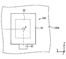
光センサの概略構成を示す平面図である。
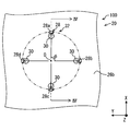
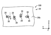
検出部の詳細構造を示す平面図である。
図3のIV-IV線に沿う断面図である。
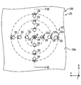
第2実施形態に係る光センサの検出部の詳細構造を示す平面図であって、図3に対応する。
図5のVI-VI線に沿う断面図である。
第1変形例に係る光センサの概略構成を示す平面図であって、図2に対応する。
第2変形例に係る光センサの検出部の詳細構造を示す断面図であって、図4に対応する。
第3変形例に係る光センサの検出部の詳細構造を示す平面図であって、図3に対応する。
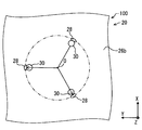
第4変形例に係る光センサの検出部の詳細構造を示す平面図であって、図3に対応する。
第5変形例に係る光センサの検出部の詳細構造を示す断面図であって、図3に対応する。
以下、本開示の実施形態を、図面を参照して説明する。なお、以下に示す各実施形態において、共通乃至関連する要素には同一の符号を付与するものとする。基板の厚さ方向をZ方向、Z方向と直交する特定の方向をX方向、X方向及びZ方向と直交する方向をY方向と示す。X方向及びY方向により規定される平面をXY平面と示す。XY平面に沿う形状を平面形状と示す。
(第1実施形態)
先ず、図1及び図2に基づき、光センサ100の概略構成について説明する。
先ず、図1及び図2に基づき、光センサ100の概略構成について説明する。
光センサ100は、入射光を検出する装置である。光センサ100は、入射光の強度、及び、進行方向に応じた検出信号を出力する。
本実施形態では、光センサ100は、車両に取り付けられるセンサである。光センサ100は、検出信号を車両に搭載された外部機器に出力する。光センサ100の検出信号は、車両の状態を制御するための信号である。
光センサ100としては、ヘッドライトのオンオフを制御するライトセンサを採用することができる。また、光センサ100としては、例えば、エアコンを制御するための検出信号を出力する日射センサを採用することもできる。光センサ100が日射センサとされた例では、光センサがエアコンECUに検出信号を出力し、エアコンECUが検出信号に基づきエアコンを制御する。さらに、光センサ100としては、例えば、HUDの輝度を調整するための検出信号を出力するセンサを採用することもできる。以下、HUDの輝度を調整するための検出信号を出力する光センサ100を、HUDセンサと示す。
さらに、光センサ100が、日射センサ、ライトセンサ、及びHUDセンサの機能うち、複数の機能を有するセンサとされた例を採用することもできる。光センサ100は、入射光の入射角度に応じた検出信号を出力するものである。
光センサ100が、入射光を検出する検出部20とは別に、雨滴を検出する検出部を有する例を採用することもできる。この例では、光センサ100が、入射光を検出するとともに、フロントガラス200の裏面200bに付着する雨滴を検出する。
光センサ100は、車両のフロントガラス200に取り付けられている。フロントガラス200は、表面(第一面)200aと、表面200aと反対の裏面(第二面)200bと、を有している。表面200aは車両室内側の面であり、裏面200bは車両外部側の面である。表面200aに光センサ100が取り付けられている。
表面200a及び裏面200bは、曲面とされている。しかしながら、表面200aにおいて光センサ100が取り付けられる部分は、XY平面に沿う平面とみなすことができる。以下、表面200aにおいて光センサ100が取り付けられる部分を、表面200aと示す。なお、Y方向は、車両が配置された路面に沿う方向とされている。Y方向の投影視において、車両が配置された路面に対して、表面200aがなす角度をガラス角度αと示す。入射光は、フロントガラス200を介して、光センサに入射する。光センサ100は、ケース10と、検出部20と、コネクタ40と、を備えている。
ケース10は、光センサ100の外郭を構成するものであり、検出部20を収容する部材である。ケース10は、図示しないブラケットにより、表面200aに固定されている。ケース10は、例えば、樹脂材料を用いて形成されている。
検出部20は、光センサ100において、入射光を検出するものである。検出部20には、フロントガラス200を介して入射光が入射される。検出部20は、入射光の強度、及び、進行方向に応じた検出信号を出力する。検出部20の詳細構造については、下記で説明する。
コネクタ40は、検出部20と、ECU等の外部機器と、を電気的に中継するものである。コネクタ40は、ケース10と一体に成形又はケース10に装着される。コネクタ40は、検出部20と電気的に接続されている。コネクタ40は、外部機器のコネクタと嵌合する。これにより、検出部20の検出信号を外部機器に出力することができる。コネクタ40は、ケース10に対して、X方向のうちフロントガラス200の上端側に形成されている。
所定の基準線に対して、Z方向を軸とする光センサ100の回転角度が所定の角度となるように、光センサ100を取り付ける。以下、Z方向を軸として、基準線に対する光センサ100の回転角度を取り付け角度βと示す。取り付け角度βは、車両外部側からの投影視において、Z方向を軸として、基準線に対して、時計回りに、ケース10の中心とコネクタ40の中心とを結ぶ線がなす角度とする。
基準線は、Z方向の投影視において、ケース10の中心から、Y方向のうち一方の方向へ向かう線である。本実施形態では、取り付け角度βが90度とされている。なお、取り付け角度βの範囲は、0度以上360度未満とする。図2では、基準線を一点鎖線、ケース10の中心とコネクタ40とを結ぶ線を二点鎖線で示している。
次に、図3及び図4に基づき、検出部20の詳細構造について説明する。なお、図3では、第1受光素子28の平面形状を明確にするために、第1受光素子28にハッチングを施す。
図3及び図4に示すように、検出部20は、基板22と、透光膜24と、遮光膜26と、を有している。基板22におけるフロントガラス200側の一面22aに対して、入射光が入射される。本実施形態において、基板22は、半導体基板とされている。基板22の一面22a側には、複数の第1受光素子28が形成されている。各第1受光素子28は、入射光の強度に応じた検出信号を出力する。
本実施形態において、第1受光素子28はフォトダイオードとされている。第1受光素子28は、基板22において、イオン注入により形成された拡散層とされている。また、本実施形態では、4個の第1受光素子28が基板22に形成されている。詳しくは、基板22の一面22a側に、第1受光素子28として、第1フォトダイオード28a、第2フォトダイオード28b、第3フォトダイオード28c、第4フォトダイオード28dが形成されている。
また、検出部20は、図示しない増幅部と処理部とを有している。増幅部は、各第1受光素子28の検出信号を増幅する。処理部は、増幅部により増幅された検出信号を積算する。処理部により積算された信号は、光センサ100の検出信号として、外部機器に出力される。一面22a上には、透光膜24が形成されている。
透光膜24は、入射光を透過する。透光膜24は、例えば、アクリル樹脂、酸化シリコンを用いて形成される。透光膜24は、一面22a上に配置されている。透光膜24における基板22と反対側の裏面24a上には、遮光膜26が配置されている。
遮光膜26は、入射光を遮光し、各第1受光素子28に対する入射光の進行方向を規定するものである。遮光膜26は、例えば、アルミニウムを用いて形成される。遮光膜26は、透光膜24側の一面26aと、一面26aと反対の裏面26bと、を有している。遮光膜26には、入射光が通過する第1開口部30が形成されている。第1開口部30は、一面26aから裏面26bにわたって形成された貫通孔である。第1開口部30は、各第1受光素子28に対応して複数形成されている。
入射光は、第1開口部30を通過するとともに、透光膜24を透過して第1受光素子28に入射する。Z方向の投影視において、第1受光素子28と第1開口部30との位置関係に応じて、第1受光素子28に対する入射光の進行方向が決定される。詳しくは、第1受光素子28の中心に対して所定の進行方向の入射光が入射するように、Z方向の投影視において、第1受光素子28の中心と、第1開口部30の中心と、の相対位置が決定される。本実施形態において、第1開口部30の平面形状は、真円形状とされている。
本実施形態では、入射光の入射角度として、第1角度θと、第2角度φと、を採用する。第1角度θとは、Z方向に沿う軸に対し、第1受光素子28に対する入射光の進行方向がなす角度である。第1角度θは、入射角度に相当する。第1角度θの範囲は、0度以上90度以下とする。第2角度φとは、車両室外側からの投影視において、所定の基準方向に対して、Z方向を軸として、時計回りに、第1受光素子28に対する入射光の進行方向がなす角度である。基準方向は、X方向のうち、フロントガラス200の下端から上端に向かう方向とする。第2角度φの範囲は、0度以上360度未満とする。
複数の第1受光素子28は、入射光の進行方向がZ方向と異なるように形成されている。すなわち、第1受光素子28及び対応する第1開口部30の位置関係は、第1角度θが0度より大きくなるように形成されている。
複数の第1受光素子28は、第1角度θが互いに同じ受光素子群32を、少なくとも1つ有している。言い換えると、遮光膜26は、複数の第1受光素子28に対して、第1角度θが互いに同じとなるように形成されている。本実施形態では、全ての第1受光素子28が、1つの受光素子群32を構成している。Z方向の投影視において、第1受光素子28及び対応する第1開口部30の距離に応じて、第1受光素子28に対する第1角度θが決定する。よって、各第1受光素子28及び対応する第1開口部30の距離は、互いにほぼ同じとされている。
Z方向の投影視において、同じ受光素子群32を構成する第1受光素子28と、対応する第1開口部30と、の位置関係が、Z方向を軸として3回以上の回転対称性を有する。言い換えると、遮光膜26は、Z方向の投影視において、第1角度θが同じとされた第1受光素子28に対する入射光の進行方向が、Z方向を軸として3回以上の回転対称性を有するように形成されている。本実施形態では、第1受光素子28と第1開口部30との位置関係が、Z方向を軸として4回の回転対称性を有する。
第1フォトダイオード28aに対する第2角度φは0度、第2フォトダイオード28bに対する第2角度φは90度とされている。第3フォトダイオード28cに対する第2角度φは180度、第4フォトダイオード28dに対する第2角度φは270度とされている。第1受光素子28及び第1開口部30が回転対称性を有する構成では、同じ受光素子群32を構成する第1受光素子28に対する第2角度φの値が、0度以上360度未満の範囲で等間隔となる。
Z方向の投影視において、第1フォトダイオード28aに対する入射光の進行方向はX方向うち一方、第3フォトダイオード28cに対する入射光の進行方向はX方向うち他方とされている。また、Z方向の投影視において、第2フォトダイオード28bに対する入射光の進行方向はY方向うち一方、第4フォトダイオード28dに対する入射光の進行方向はY方向うち他方とされている。
一面22aにおいて、複数の第1受光素子28は、真円形状をなす円形パターン上に配置されている。図3では、円形パターンを二点鎖線で示す。以下、円形パターンの中心を中心Oと示す。Z方向の投影視において、中心Oと、各第1受光素子28と、を結ぶ線上に第1開口部30が形成されている。
Z方向の投影視において、第1受光素子28は、対応する第1開口部30よりも中心Oから遠くなるように、第1受光素子28及び第1開口部30が形成されている。Z方向の投影視において、第1受光素子28及び第1開口部30の位置関係が、中心Oを通るとともにZ方向に沿う方向を軸として、4回の回転対称性を有する。
上記したように、各第1開口部30は、対応する第1受光素子28の中心に対して、所定の入射角度の入射光が入射するように形成されている。これに対し、第1受光素子28の中心以外の部分にも入射光が入射される。第1受光素子28の平面形状、及び、その面積に応じて、第1受光素子28に対する入射角度の範囲が決定される。
各第1受光素子28の平面形状は、Z方向を軸として、互いに回転対称な形状とされている。本実施形態では、各第1受光素子28の平面形状が、中心Oを通るとともにZ方向に沿う方向を軸として、互いに4回の回転対称な形状とされている。
また、各第1受光素子28の平面形状は、円環を等分してなる扇形状をなしている。第1受光素子28の平面形状は、対応する第1開口部30の中心との最短距離が互いに同じとなるように形成されている。詳しくは、Z方向の投影視において、第1受光素子28における扇形状の内周における各部分と、第1開口部30の中心と、の最短距離が互いに同じとされている。Z方向の投影視において、各第1受光素子28における扇形状の中心角は、90度とされている。これにより、各第1受光素子28が受光可能な第2角度φの範囲は、90度とされている。
第1フォトダイオード28aが受光可能な第2角度φの範囲は、0度以上45度以下、及び、315度以上360度未満とされている。第2フォトダイオード28bが受光可能な第2角度φの範囲は、45度以上135度以下とされている。第3フォトダイオード28cが受光可能な第2角度φの範囲は、135度以上225度以下とされている。第4フォトダイオード28dが受光可能な第2角度φの範囲は、225度以上315度以下とされている。
次に、上記した光センサ100の効果について説明する。
本実施形態では、同じ受光素子群32を構成する第1受光素子28と、対応する第1開口部30と、の位置関係が、Z方向を軸として3回以上の回転対称性を有する。これによれば、Z方向を軸に光センサ100を回転させると、第1受光素子28及び第1開口部30の位置関係が同じとなる取り付け角度βが、3つ以上ある。言い換えると、Z方向を軸に光センサ100を回転させると、検出特性が近くなる取り付け角度βが、3つ以上ある。したがって、取り付け角度βが1つに固定されることなく、光センサ100の配置自由度を向上することができる。
ところで、Z方向を軸として、第1受光素子28と第1開口部30との位置関係における回転対称が2回のみとされた構成が考えられる。しかしながら、この構成では、所定の第2角度φとされた入射光が第1受光素子28に入射し難い虞がある。これに対し、各第1受光素子28に対する第2角度φの範囲を大きくするため、第1受光素子28の平面形状の面積を大きくする構成が考えられる。しかしながら、この構成では、光センサ100が、第2角度φの異なる入射光を判別し難く、第2角度φに対する検出精度が低下する虞がある。
これらに対し、回転対称性が3回以上とされた本実施形態では、第1受光素子28の平面形状の面積を大きくすることなく、光センサ100の検出可能な第2角度φの範囲を大きくすることができる。したがって、光センサ100が、検出可能な第2角度φの範囲を大きくしつつ、第2角度φに対する検出精度の低下を抑制することができる。
また、本実施形態では、各第1受光素子28の平面形状は、Z方向を軸として、互いに回転対称な形状とされている。これによれば、各第1受光素子28における検出特性をより近くすることができる。すなわち、互いに異なる取り付け角度βで取り付けた光センサ100の検出特性をより近くすることができる。よって、光センサ100を異なる取り付け角度βで取り付け易く、光センサ100の配置自由度をより向上することができる。
ところで、第1開口部30を通過する入射光は、遮光膜26から基板22へ向かうほど、Z方向の投影視において第1開口部30から離れる。よって、第1開口部30を所定の第1角度θで通過する入射光が、一面22aに入射可能な範囲は、Z方向の投影視において、円環形状をなす。Z方向の投影視において、この円環形状の中心は、第1開口部の中心と一致している。
これに対し、本実施形態では、各第1受光素子の平面形状は、円環を等分してなる扇形状をなすとともに、対応する第1開口部30の中心との最短距離が互いに同じとなるように形成されている。言い換えると、第1受光素子28の平面形状は、対応する第1開口部30を所定の第1角度θで通過する入射光の入射可能な全ての範囲に合わせた形状とされている。
これによれば、受光素子群32に対して、第1角度θの範囲を狭くしつつ、第2角度φにおける全ての範囲の入射光が入射される。したがって、光センサ100において、第1角度θの検出精度を向上することができ、且つ、全ての取り付け角度βで取り付けることができる。すなわち、第1角度θの検出精度を向上しつつ、光センサ100の配置自由度をより向上することができる。
また、本実施形態では、第1受光素子28と、対応する第1開口部30と、の位置関係が、Z方向を軸として、偶数回の回転対称性を有する。これによれば、Z方向を軸として、光センサ100を180度回転させて配置した場合の検出特性を近くすることができる。よって、光センサ100を、所定の取り付け角度βから、180度回転させて配置し易い。
(第2実施形態)
本実施形態において、第1実施形態に示した光センサ100と共通する部分についての説明は割愛する。なお、図5では、第1受光素子28及び第2受光素子34の平面形状を明確にするために、第1受光素子28及び第2受光素子34にハッチングを施す。
本実施形態において、第1実施形態に示した光センサ100と共通する部分についての説明は割愛する。なお、図5では、第1受光素子28及び第2受光素子34の平面形状を明確にするために、第1受光素子28及び第2受光素子34にハッチングを施す。
図5及び図6に示すように、複数の第1受光素子28は、受光素子群32を複数有している。各受光素子群32に対する第1角度θは、互いに異なる。本実施形態では、複数の第1受光素子28が、受光素子群32として、第1受光素子群32a、第2受光素子群32b、第3受光素子群32cを有している。
第1受光素子群32aに対する第1角度θは、第2受光素子群32bに対する第1角度θよりも大きくされている。よって、Z方向の投影視において、第1受光素子28と第1開口部30との距離は、第1受光素子群32aの方が、第2受光素子群32bよりも短くされている。第2受光素子群32bに対する第1角度θは、第3受光素子群32cに対する第1角度θよりも大きくされている。そのため、Z方向の投影視において、第1受光素子28と第1開口部30との距離は、第2受光素子群32bの方が、第3受光素子群32cよりも短くされている。
各受光素子群32は、4つの第1受光素子28により構成されている。全ての受光素子群32では、Z方向の投影視における第1受光素子28と第1開口部30との位置関係が、Z方向を軸として、4回の回転対称性を有する。言い換えると、遮光膜26は、受光素子群32毎に、Z方向の投影視における第1受光素子28に対する入射光の進行方向が、Z方向を軸として、4回の回転対称性を有するように形成されている。
第1実施形態と同様に、一面22aにおいて、複数の第1受光素子28は、真円形状をなす円形パターン上に形成されている。受光素子群32毎に、互いに異なる円形パターン上に、第1受光素子28が形成されている。各受光素子群32の円形パターンの中心は、互いにほぼ一致している。第1受光素子群32aの円形パターンの径は、第2受光素子群32bの円形パターンの径よりも短くされている。第2受光素子群32bの円形パターンの径は、第3受光素子群32cの円形パターンの径よりも短くされている。
検出部20は、第1受光素子28に対する第1角度θと異なる角度で入射光が入射される第2受光素子34を有している。基板22の一面22a側における、第1受光素子28が形成された箇所と異なる箇所に、第2受光素子34が形成されている。本実施形態において、第2受光素子34に対する第1角度θは、0度とされている。第2受光素子34は、第1受光素子28と同様に、入射光の強度に応じた検出信号を出力する。本実施形態では、第2受光素子34が、フォトダイオードとされている。第2受光素子34の平面形状は、真円形状とされている。
遮光膜26は、第2受光素子34に対応して形成された第2開口部36を有している。Z方向の投影視において、第2開口部36は、第2受光素子34とほぼ同じ位置に形成されている。第2受光素子34の平面形状は、真円形状とされている。第2開口部36は、第1開口部30と同様に、一面26aから裏面26bにわたって形成された貫通孔である。
ところで、ガラス角度αが互いに異なるフロントガラス200に光センサ100を取り付ける構成では、同じ入射光であっても、光センサ100に対する入射角度が異なる。これによれば、第1受光素子28及び第1開口部30が所定の位置関係となるように設計した光センサ100については、取り付け可能なガラス角度αが固定されることとなる。
これに対し、本実施形態において、複数の第1受光素子28は、第1角度θが互いに異なる受光素子群32を複数有している。そのため、光センサ100は、複数の第1角度θの入射光を検出可能である。言い換えると、ガラス角度αが互いに異なるフロントガラス200に取り付けた場合であっても、いずれかの受光素子群32が入射光を受光し易い。したがって、ガラス角度αが互いに異なるフロントガラス200に対して光センサ100を取り付け易く、光センサ100の配置自由度を向上することができる。
また、本実施形態では、第1受光素子28に対する第1角度θと異なる第1角度θで入射光が入射する第2受光素子34が、基板22に形成されている。よって、光センサ100が検出可能な第1角度θの範囲を広くすることができる。したがって、ガラス角度αが互いに異なるフロントガラス200に対して光センサ100を取り付け易く、光センサ100の配置自由度を向上することができる。
本開示は、実施形態に準拠して記述されたが、本開示は当該実施形態や構造に限定されるものではないと理解される。本開示は、様々な変形例や均等範囲内の変形をも包含する。加えて、様々な組み合わせや形態、さらには、それらに一要素のみ、それ以上、あるいはそれ以下、を含む他の組み合わせや形態をも、本開示の範疇や思想範囲に入るものである。
上記実施形態では、取り付け角度βが90度とされた例を示したが、これに限定するものではない。図7の第1変形例に示すように、取り付け角度βが270度とされた例を採用することもできる。第1変形例では、光センサ100の検出特性を、上記実施形態における光センサ100の検出特性と近くすることができる。
また、上記実施形態では、遮光膜26が1つとされた例を示したが、これに限定するものではない。図8の第2変形例に示すように、検出部20が、複数の遮光膜26を有する例を採用することもできる。第2変形例では、検出部20が、2つの透光膜24と、2つの遮光膜26と、を有している。複数の透光膜24及び複数の遮光膜26は、互いに積層されている。また、第2変形例では、基板22に第2受光素子34が形成されている。
Z方向のうち、検出部20からフロントガラス200へ向かう方向において、基板22、透光膜24、遮光膜26、透光膜24、遮光膜26の順に積層されている。各遮光膜26には、第1開口部30及び第2開口部36が形成されている。
第1開口部30は、対応する第1受光素子28に対して、第1角度θが所定の角度となるように形成されている。そのため、Z方向の投影視において、互いに同じ第1受光素子28に対応する各遮光膜26の第1開口部30は、異なる位置に形成されている。第2開口部36は、対応する第2受光素子34に対して、第1角度θが0度となるように形成されている。そのため、Z方向の投影視において、互いに同じ第2受光素子34に対応する各遮光膜26の第2開口部36は、同じ位置に形成されている。
また、検出部20が、透光膜24を有さない例を採用することもできる。例えば、一面22a上に遮光膜26のみが配置され、遮光膜26の第1開口部30により各第1受光素子28に対する入射光の進行方向が規定される。
また、上記実施形態では、第1受光素子28と第1開口部30との位置関係が、Z方向を軸として、4回の回転対称性を有する例を示したが、これに限定するものではない。図9の第3変形例に示すように、第1受光素子28と第1開口部30との位置関係が、Z方向を軸として、8回の回転対称性を有する例を採用することもできる。また、図10の第4変形例に示すように、第1受光素子28と第1開口部30との位置関係が、Z方向を軸として、3回の回転対称性を有する例を採用することもできる。
また、上記実施形態では、複数の第1受光素子28が円形パターン上に並んで形成された例を示したが、これに限定するものではない。一面22aにおける複数の第1受光素子28同士の相対位置は、限定されない。図11の第5変形例に示すように、複数の第1受光素子28がY方向に並んで形成された例を採用することもできる。
第5変形例では、第1実施形態と同様に、4つの第1受光素子28が基板22に形成されている。各第1受光素子28と、対応する第1開口部30と、の位置関係が、Z方向を軸として、4回の回転対称性を有するように形成されている。第1受光素子28及び第1開口部30の位置関係における回転対称性は、Z方向の投影視における第1受光素子28及び第1開口部30の相対位置、すなわち第1角度θ及び第2角度φにより決定される。
第5変形例では、各第1受光素子28に対して、第1角度θが互いに同じとされ、且つ、第2角度φの値が、0度以上360度未満の範囲で、等間隔とされている。そのため、第1受光素子28及び第1開口部30の位置関係は、Z方向を軸として回転対称性を有している。
また、上記実施形態では、第1受光素子28の平面形状が扇形状とされた例を示したが、これに限定するものではない。第1受光素子28の平面形状が、例えば、真円形状、矩形状とされた例を採用する事もできる。また、上記実施形態では、各第1受光素子28の平面形状が、Z方向を軸として、互いに回転対称な形状とされた例を示したが、これに限定するものではない。
Claims (7)
- 入射光の強度に応じた検出信号を出力する複数の第1受光素子(28)を一面(22a)に有する基板(22)と、
前記基板の前記一面側に配置されるとともに、各第1受光素子に対応する第1開口部(30)を複数有し、各第1受光素子に対する入射光の進行方向を規定する遮光膜(26)と、を備える光センサであって、
複数の前記第1受光素子は、入射光の進行方向が前記基板の厚さ方向と異なるように設けられ、且つ、入射光の進行方向と前記厚さ方向とのなす入射角度が互いに同じ受光素子群(32)を少なくとも1つ有し、
前記厚さ方向の投影視において、同じ前記受光素子群を構成する前記第1受光素子と、対応する前記第1開口部と、の位置関係は、前記厚さ方向を軸として3回以上の回転対称性を有する光センサ。 - 複数の前記第1受光素子は、前記受光素子群を複数有し、
各受光素子群に対する入射角度は、互いに異なる請求項1に記載の光センサ。 - 前記厚さ方向の投影視において、同じ前記受光素子群を構成する前記第1受光素子は、前記厚さ方向を軸として互いに回転対称な形状とされている請求項1又は請求項2に記載の光センサ。
- 前記厚さ方向の投影視において、同じ前記受光素子群を構成する前記第1受光素子は、円環を等分してなる扇形状をなすとともに、対応する前記第1開口部の中心との最短距離が互いに同じとなるように設けられている請求項3に記載の光センサ。
- 前記厚さ方向の投影視において、同じ前記受光素子群を構成する前記第1受光素子と、対応する前記第1開口部と、の位置関係が、前記厚さ方向を軸として偶数回の回転対称性を有するように設けられている請求項1~4のいずれか1項に記載の光センサ。
- 前記基板の一面側における前記第1受光素子が設けられた箇所と異なる箇所には、入射光の強度に応じた検出信号を出力する第2受光素子(34)が設けられ、
前記遮光膜は、前記第2受光素子に対して、前記第1受光素子に対する入射角度と異なる入射角度で入射光を入射させる第2開口部(36)を有する請求項1~5のいずれか1項に記載の光センサ。 - 複数の前記遮光膜を備え、
複数の前記遮光膜は、互いに積層されている請求項1~6のいずれか1項に記載の光センサ。
Priority Applications (3)
| Application Number | Priority Date | Filing Date | Title |
|---|---|---|---|
| DE112016001021.4T DE112016001021T5 (de) | 2015-03-03 | 2016-02-12 | Optischer sensor |
| CN201680013247.4A CN107430027A (zh) | 2015-03-03 | 2016-02-12 | 光传感器 |
| US15/547,108 US10444066B2 (en) | 2015-03-03 | 2016-02-12 | Optical sensor |
Applications Claiming Priority (2)
| Application Number | Priority Date | Filing Date | Title |
|---|---|---|---|
| JP2015-041628 | 2015-03-03 | ||
| JP2015041628A JP2016161458A (ja) | 2015-03-03 | 2015-03-03 | 光センサ |
Publications (1)
| Publication Number | Publication Date |
|---|---|
| WO2016139897A1 true WO2016139897A1 (ja) | 2016-09-09 |
Family
ID=56844872
Family Applications (1)
| Application Number | Title | Priority Date | Filing Date |
|---|---|---|---|
| PCT/JP2016/000718 Ceased WO2016139897A1 (ja) | 2015-03-03 | 2016-02-12 | 光センサ |
Country Status (5)
| Country | Link |
|---|---|
| US (1) | US10444066B2 (ja) |
| JP (1) | JP2016161458A (ja) |
| CN (1) | CN107430027A (ja) |
| DE (1) | DE112016001021T5 (ja) |
| WO (1) | WO2016139897A1 (ja) |
Families Citing this family (5)
| Publication number | Priority date | Publication date | Assignee | Title |
|---|---|---|---|---|
| JP6760152B2 (ja) * | 2017-03-14 | 2020-09-23 | 株式会社デンソー | ライトセンサ |
| JP7165603B2 (ja) * | 2019-03-04 | 2022-11-04 | 三菱重工業株式会社 | 積層体成形装置の校正部材、積層体成形装置及び積層体成形方法 |
| KR102777745B1 (ko) * | 2019-05-10 | 2025-03-06 | 현대자동차주식회사 | 포토 센서 구조 |
| WO2020229383A1 (de) | 2019-05-14 | 2020-11-19 | Saint-Gobain Glass France | Verglasungseinheit eines fahrzeugs oder gebäudes sowie verglasungsanordnung |
| JP2024126348A (ja) * | 2023-03-07 | 2024-09-20 | 富士フイルムビジネスイノベーション株式会社 | 画像読み取り装置および画像形成システム |
Citations (3)
| Publication number | Priority date | Publication date | Assignee | Title |
|---|---|---|---|---|
| JP2011504225A (ja) * | 2007-10-26 | 2011-02-03 | コーニンクレッカ フィリップス エレクトロニクス エヌ ヴィ | 光角度選択型光検出装置 |
| JP2012103126A (ja) * | 2010-11-10 | 2012-05-31 | Denso Corp | 光センサ装置 |
| JP2013045779A (ja) * | 2011-08-21 | 2013-03-04 | Denso Corp | 光センサ |
Family Cites Families (7)
| Publication number | Priority date | Publication date | Assignee | Title |
|---|---|---|---|---|
| US6521882B1 (en) | 1998-03-27 | 2003-02-18 | Denso Corporation | Optical sensor with directivity controlled |
| JP2005249478A (ja) | 2004-03-02 | 2005-09-15 | Denso Corp | 光センサ |
| US7865803B2 (en) * | 2004-04-30 | 2011-01-04 | Mediatek Inc. | Method for processing noise interference in data accessing device with serial advanced technology attachment (SATA) interface |
| JP2009288195A (ja) * | 2008-05-30 | 2009-12-10 | Fujitsu Ltd | 電波方向検出器およびアンテナ可動装置 |
| US8901480B2 (en) | 2010-09-10 | 2014-12-02 | Denso Corporation | Optical sensor having a blocking film disposed over light receiving elements on a semiconductor substrate via a light transparent film for detecting an incident angle of light |
| US8290011B2 (en) * | 2010-11-22 | 2012-10-16 | The United States Of America, As Represented By The Secretary Of The Navy | Interband cascade lasers |
| JP5971106B2 (ja) | 2012-12-17 | 2016-08-17 | 株式会社デンソー | 光センサ |
-
2015
- 2015-03-03 JP JP2015041628A patent/JP2016161458A/ja active Pending
-
2016
- 2016-02-12 DE DE112016001021.4T patent/DE112016001021T5/de not_active Ceased
- 2016-02-12 CN CN201680013247.4A patent/CN107430027A/zh active Pending
- 2016-02-12 US US15/547,108 patent/US10444066B2/en not_active Expired - Fee Related
- 2016-02-12 WO PCT/JP2016/000718 patent/WO2016139897A1/ja not_active Ceased
Patent Citations (3)
| Publication number | Priority date | Publication date | Assignee | Title |
|---|---|---|---|---|
| JP2011504225A (ja) * | 2007-10-26 | 2011-02-03 | コーニンクレッカ フィリップス エレクトロニクス エヌ ヴィ | 光角度選択型光検出装置 |
| JP2012103126A (ja) * | 2010-11-10 | 2012-05-31 | Denso Corp | 光センサ装置 |
| JP2013045779A (ja) * | 2011-08-21 | 2013-03-04 | Denso Corp | 光センサ |
Also Published As
| Publication number | Publication date |
|---|---|
| JP2016161458A (ja) | 2016-09-05 |
| US20180010960A1 (en) | 2018-01-11 |
| DE112016001021T5 (de) | 2017-11-23 |
| CN107430027A (zh) | 2017-12-01 |
| US10444066B2 (en) | 2019-10-15 |
Similar Documents
| Publication | Publication Date | Title |
|---|---|---|
| WO2016139897A1 (ja) | 光センサ | |
| JP5815312B2 (ja) | 周囲条件を検出するためのセンサー・アレンジメント | |
| JP4134912B2 (ja) | 光検出器 | |
| CN110073201B (zh) | 集成的雨和太阳辐射传感模块 | |
| US20260050065A1 (en) | Split Window and Baffling | |
| CN110824455B (zh) | 传感器系统 | |
| JP2007206078A (ja) | 物体の近接を検出する方法およびシステム | |
| JP4826620B2 (ja) | 光検出装置 | |
| US20110240862A1 (en) | Solar sensor for the detection of the direction of incidence and the intensity of solar radiation | |
| EP3537118A1 (en) | Radiation sensor, vehicle sensor arrangement, and assembly method | |
| WO2013157258A1 (ja) | 光センサ | |
| US8705014B2 (en) | Radiation sensor for detecting the position and intensity of a radiation source | |
| JP2015219223A (ja) | 光センサ | |
| CN106443817A (zh) | 回归反射型光电传感器 | |
| CN113169165B (zh) | 光电设备和用于其制造的方法 | |
| JP2005233726A (ja) | 照度検出器 | |
| JPH046413A (ja) | 回転角検出装置 | |
| US20240393467A1 (en) | Light detection device and light detection system | |
| JP4598981B2 (ja) | 日照センサ | |
| JPH0587537U (ja) | 自動車用空気調和装置の日射量検出センサー | |
| JP3080630B2 (ja) | 半導体振動センサー | |
| JP2008085153A (ja) | 反射型フォトインタラプタ | |
| JP3114368B2 (ja) | 車両空調用日射センサ | |
| JPH0713516U (ja) | 日射検出センサ | |
| CA2388082A1 (en) | Sunload sensor for automotive vehicles |
Legal Events
| Date | Code | Title | Description |
|---|---|---|---|
| 121 | Ep: the epo has been informed by wipo that ep was designated in this application |
Ref document number: 16758598 Country of ref document: EP Kind code of ref document: A1 |
|
| WWE | Wipo information: entry into national phase |
Ref document number: 15547108 Country of ref document: US |
|
| WWE | Wipo information: entry into national phase |
Ref document number: 112016001021 Country of ref document: DE |
|
| 122 | Ep: pct application non-entry in european phase |
Ref document number: 16758598 Country of ref document: EP Kind code of ref document: A1 |