WO2016136248A1 - 電源装置及びこれを備える車両 - Google Patents
電源装置及びこれを備える車両 Download PDFInfo
- Publication number
- WO2016136248A1 WO2016136248A1 PCT/JP2016/000976 JP2016000976W WO2016136248A1 WO 2016136248 A1 WO2016136248 A1 WO 2016136248A1 JP 2016000976 W JP2016000976 W JP 2016000976W WO 2016136248 A1 WO2016136248 A1 WO 2016136248A1
- Authority
- WO
- WIPO (PCT)
- Prior art keywords
- power supply
- battery
- secondary battery
- supply device
- battery stack
- Prior art date
- Legal status (The legal status is an assumption and is not a legal conclusion. Google has not performed a legal analysis and makes no representation as to the accuracy of the status listed.)
- Ceased
Links
Images





Classifications
-
- H—ELECTRICITY
- H01—ELECTRIC ELEMENTS
- H01M—PROCESSES OR MEANS, e.g. BATTERIES, FOR THE DIRECT CONVERSION OF CHEMICAL ENERGY INTO ELECTRICAL ENERGY
- H01M50/00—Constructional details or processes of manufacture of the non-active parts of electrochemical cells other than fuel cells, e.g. hybrid cells
- H01M50/50—Current conducting connections for cells or batteries
- H01M50/572—Means for preventing undesired use or discharge
- H01M50/574—Devices or arrangements for the interruption of current
- H01M50/578—Devices or arrangements for the interruption of current in response to pressure
-
- B—PERFORMING OPERATIONS; TRANSPORTING
- B60—VEHICLES IN GENERAL
- B60L—PROPULSION OF ELECTRICALLY-PROPELLED VEHICLES; SUPPLYING ELECTRIC POWER FOR AUXILIARY EQUIPMENT OF ELECTRICALLY-PROPELLED VEHICLES; ELECTRODYNAMIC BRAKE SYSTEMS FOR VEHICLES IN GENERAL; MAGNETIC SUSPENSION OR LEVITATION FOR VEHICLES; MONITORING OPERATING VARIABLES OF ELECTRICALLY-PROPELLED VEHICLES; ELECTRIC SAFETY DEVICES FOR ELECTRICALLY-PROPELLED VEHICLES
- B60L58/00—Methods or circuit arrangements for monitoring or controlling batteries or fuel cells, specially adapted for electric vehicles
- B60L58/10—Methods or circuit arrangements for monitoring or controlling batteries or fuel cells, specially adapted for electric vehicles for monitoring or controlling batteries
- B60L58/18—Methods or circuit arrangements for monitoring or controlling batteries or fuel cells, specially adapted for electric vehicles for monitoring or controlling batteries of two or more battery modules
- B60L58/21—Methods or circuit arrangements for monitoring or controlling batteries or fuel cells, specially adapted for electric vehicles for monitoring or controlling batteries of two or more battery modules having the same nominal voltage
-
- H—ELECTRICITY
- H01—ELECTRIC ELEMENTS
- H01M—PROCESSES OR MEANS, e.g. BATTERIES, FOR THE DIRECT CONVERSION OF CHEMICAL ENERGY INTO ELECTRICAL ENERGY
- H01M50/00—Constructional details or processes of manufacture of the non-active parts of electrochemical cells other than fuel cells, e.g. hybrid cells
- H01M50/20—Mountings; Secondary casings or frames; Racks, modules or packs; Suspension devices; Shock absorbers; Transport or carrying devices; Holders
- H01M50/204—Racks, modules or packs for multiple batteries or multiple cells
- H01M50/207—Racks, modules or packs for multiple batteries or multiple cells characterised by their shape
- H01M50/209—Racks, modules or packs for multiple batteries or multiple cells characterised by their shape adapted for prismatic or rectangular cells
-
- H—ELECTRICITY
- H01—ELECTRIC ELEMENTS
- H01M—PROCESSES OR MEANS, e.g. BATTERIES, FOR THE DIRECT CONVERSION OF CHEMICAL ENERGY INTO ELECTRICAL ENERGY
- H01M50/00—Constructional details or processes of manufacture of the non-active parts of electrochemical cells other than fuel cells, e.g. hybrid cells
- H01M50/20—Mountings; Secondary casings or frames; Racks, modules or packs; Suspension devices; Shock absorbers; Transport or carrying devices; Holders
- H01M50/218—Mountings; Secondary casings or frames; Racks, modules or packs; Suspension devices; Shock absorbers; Transport or carrying devices; Holders characterised by the material
- H01M50/22—Mountings; Secondary casings or frames; Racks, modules or packs; Suspension devices; Shock absorbers; Transport or carrying devices; Holders characterised by the material of the casings or racks
- H01M50/227—Organic material
-
- H—ELECTRICITY
- H01—ELECTRIC ELEMENTS
- H01M—PROCESSES OR MEANS, e.g. BATTERIES, FOR THE DIRECT CONVERSION OF CHEMICAL ENERGY INTO ELECTRICAL ENERGY
- H01M50/00—Constructional details or processes of manufacture of the non-active parts of electrochemical cells other than fuel cells, e.g. hybrid cells
- H01M50/20—Mountings; Secondary casings or frames; Racks, modules or packs; Suspension devices; Shock absorbers; Transport or carrying devices; Holders
- H01M50/249—Mountings; Secondary casings or frames; Racks, modules or packs; Suspension devices; Shock absorbers; Transport or carrying devices; Holders specially adapted for aircraft or vehicles, e.g. cars or trains
-
- H—ELECTRICITY
- H01—ELECTRIC ELEMENTS
- H01M—PROCESSES OR MEANS, e.g. BATTERIES, FOR THE DIRECT CONVERSION OF CHEMICAL ENERGY INTO ELECTRICAL ENERGY
- H01M50/00—Constructional details or processes of manufacture of the non-active parts of electrochemical cells other than fuel cells, e.g. hybrid cells
- H01M50/20—Mountings; Secondary casings or frames; Racks, modules or packs; Suspension devices; Shock absorbers; Transport or carrying devices; Holders
- H01M50/262—Mountings; Secondary casings or frames; Racks, modules or packs; Suspension devices; Shock absorbers; Transport or carrying devices; Holders with fastening means, e.g. locks
- H01M50/264—Mountings; Secondary casings or frames; Racks, modules or packs; Suspension devices; Shock absorbers; Transport or carrying devices; Holders with fastening means, e.g. locks for cells or batteries, e.g. straps, tie rods or peripheral frames
-
- H—ELECTRICITY
- H01—ELECTRIC ELEMENTS
- H01M—PROCESSES OR MEANS, e.g. BATTERIES, FOR THE DIRECT CONVERSION OF CHEMICAL ENERGY INTO ELECTRICAL ENERGY
- H01M50/00—Constructional details or processes of manufacture of the non-active parts of electrochemical cells other than fuel cells, e.g. hybrid cells
- H01M50/20—Mountings; Secondary casings or frames; Racks, modules or packs; Suspension devices; Shock absorbers; Transport or carrying devices; Holders
- H01M50/271—Lids or covers for the racks or secondary casings
-
- H—ELECTRICITY
- H01—ELECTRIC ELEMENTS
- H01M—PROCESSES OR MEANS, e.g. BATTERIES, FOR THE DIRECT CONVERSION OF CHEMICAL ENERGY INTO ELECTRICAL ENERGY
- H01M50/00—Constructional details or processes of manufacture of the non-active parts of electrochemical cells other than fuel cells, e.g. hybrid cells
- H01M50/50—Current conducting connections for cells or batteries
- H01M50/572—Means for preventing undesired use or discharge
- H01M50/574—Devices or arrangements for the interruption of current
- H01M50/581—Devices or arrangements for the interruption of current in response to temperature
-
- H—ELECTRICITY
- H01—ELECTRIC ELEMENTS
- H01M—PROCESSES OR MEANS, e.g. BATTERIES, FOR THE DIRECT CONVERSION OF CHEMICAL ENERGY INTO ELECTRICAL ENERGY
- H01M2200/00—Safety devices for primary or secondary batteries
- H01M2200/10—Temperature sensitive devices
- H01M2200/103—Fuse
-
- H—ELECTRICITY
- H01—ELECTRIC ELEMENTS
- H01M—PROCESSES OR MEANS, e.g. BATTERIES, FOR THE DIRECT CONVERSION OF CHEMICAL ENERGY INTO ELECTRICAL ENERGY
- H01M2200/00—Safety devices for primary or secondary batteries
- H01M2200/20—Pressure-sensitive devices
-
- H—ELECTRICITY
- H01—ELECTRIC ELEMENTS
- H01M—PROCESSES OR MEANS, e.g. BATTERIES, FOR THE DIRECT CONVERSION OF CHEMICAL ENERGY INTO ELECTRICAL ENERGY
- H01M2220/00—Batteries for particular applications
- H01M2220/20—Batteries in motive systems, e.g. vehicle, ship, plane
-
- H—ELECTRICITY
- H01—ELECTRIC ELEMENTS
- H01M—PROCESSES OR MEANS, e.g. BATTERIES, FOR THE DIRECT CONVERSION OF CHEMICAL ENERGY INTO ELECTRICAL ENERGY
- H01M50/00—Constructional details or processes of manufacture of the non-active parts of electrochemical cells other than fuel cells, e.g. hybrid cells
- H01M50/20—Mountings; Secondary casings or frames; Racks, modules or packs; Suspension devices; Shock absorbers; Transport or carrying devices; Holders
- H01M50/289—Mountings; Secondary casings or frames; Racks, modules or packs; Suspension devices; Shock absorbers; Transport or carrying devices; Holders characterised by spacing elements or positioning means within frames, racks or packs
- H01M50/293—Mountings; Secondary casings or frames; Racks, modules or packs; Suspension devices; Shock absorbers; Transport or carrying devices; Holders characterised by spacing elements or positioning means within frames, racks or packs characterised by the material
-
- H—ELECTRICITY
- H01—ELECTRIC ELEMENTS
- H01M—PROCESSES OR MEANS, e.g. BATTERIES, FOR THE DIRECT CONVERSION OF CHEMICAL ENERGY INTO ELECTRICAL ENERGY
- H01M50/00—Constructional details or processes of manufacture of the non-active parts of electrochemical cells other than fuel cells, e.g. hybrid cells
- H01M50/50—Current conducting connections for cells or batteries
- H01M50/502—Interconnectors for connecting terminals of adjacent batteries; Interconnectors for connecting cells outside a battery casing
- H01M50/507—Interconnectors for connecting terminals of adjacent batteries; Interconnectors for connecting cells outside a battery casing comprising an arrangement of two or more busbars within a container structure, e.g. busbar modules
-
- Y—GENERAL TAGGING OF NEW TECHNOLOGICAL DEVELOPMENTS; GENERAL TAGGING OF CROSS-SECTIONAL TECHNOLOGIES SPANNING OVER SEVERAL SECTIONS OF THE IPC; TECHNICAL SUBJECTS COVERED BY FORMER USPC CROSS-REFERENCE ART COLLECTIONS [XRACs] AND DIGESTS
- Y02—TECHNOLOGIES OR APPLICATIONS FOR MITIGATION OR ADAPTATION AGAINST CLIMATE CHANGE
- Y02E—REDUCTION OF GREENHOUSE GAS [GHG] EMISSIONS, RELATED TO ENERGY GENERATION, TRANSMISSION OR DISTRIBUTION
- Y02E60/00—Enabling technologies; Technologies with a potential or indirect contribution to GHG emissions mitigation
- Y02E60/10—Energy storage using batteries
-
- Y—GENERAL TAGGING OF NEW TECHNOLOGICAL DEVELOPMENTS; GENERAL TAGGING OF CROSS-SECTIONAL TECHNOLOGIES SPANNING OVER SEVERAL SECTIONS OF THE IPC; TECHNICAL SUBJECTS COVERED BY FORMER USPC CROSS-REFERENCE ART COLLECTIONS [XRACs] AND DIGESTS
- Y02—TECHNOLOGIES OR APPLICATIONS FOR MITIGATION OR ADAPTATION AGAINST CLIMATE CHANGE
- Y02T—CLIMATE CHANGE MITIGATION TECHNOLOGIES RELATED TO TRANSPORTATION
- Y02T10/00—Road transport of goods or passengers
- Y02T10/60—Other road transportation technologies with climate change mitigation effect
- Y02T10/70—Energy storage systems for electromobility, e.g. batteries
Definitions
- the present invention relates to a power supply device formed by stacking a plurality of secondary batteries that can be charged and discharged, and a vehicle including the power supply device.
- the power supply device for the vehicle increases the output voltage of the battery block by connecting a large number of chargeable / dischargeable secondary batteries in series as a battery block. .
- This power supply device is discharged by supplying electric power to the motor while the vehicle is running, and is charged by a generator during regenerative braking of the vehicle.
- the discharge current of the battery specifies the driving torque of the motor
- the charging current of the battery specifies the braking force for regenerative braking. Therefore, in order to increase the driving torque of the motor that accelerates the vehicle, it is necessary to increase the discharge current of the battery, and in order to increase the regenerative braking of the vehicle, it is necessary to charge with a large current.
- the battery of the power supply device for vehicles is discharged and charged with a large current.
- a battery with a built-in current interrupting mechanism (Current Interrupt Device) has been developed to cut off the current when the internal pressure of the battery becomes abnormally high. .
- the secondary battery 101 includes an electrode body 115, a current collector plate 116 connected to the electrode body 115, an outer can 111 that houses the electrode body 115, and a sealing that seals the outer can 111.
- a plate 112 a reversing plate 122 having an edge coupled to the sealing plate 112 and formed of a conductive material, and a connection plate 123 insulated from the sealing plate 112 by an insulating member 124 and having a different polarity.
- the current collector plate 116 is provided with a fuse portion 121 that is melted by heat due to overcurrent.
- the reversing plate 122 swells toward the inner region of the outer can 111 under normal conditions, and has a structure that is reversed when the pressure in the battery becomes higher than the set pressure.
- the reversing plate 122 is reversed to contact the connection plate 123 and short-circuit inside the secondary battery 101.
- the fuse portion 121 provided on the current collector plate 116 is melted by heat, and the electrical connection between the electrode terminal of the battery and the electrode body 115 is disconnected.
- a power supply device for a vehicle when the fuse portion is blown, the current is cut off and the motor cannot be driven.
- the vehicle in a hybrid car or the like, the vehicle can be driven by an engine.
- the engine runs in this state, it is conceivable that the blown melted portion comes into contact with the secondary battery and sparks are generated due to re-conduction.
- a secondary battery mounted on a vehicle cannot eliminate vibrations caused by running of the vehicle, and it is considered that sparks due to re-conduction are likely to occur when the fusing parts come into contact with each other due to external vibrations.
- the present inventors cannot eliminate the occurrence of sparks at the time of fusing or re-conduction in a secondary battery having a current interruption mechanism that cuts off the current by fusing the fuse part. I thought it necessary to take measures to prevent the sparks from flying outside.
- the present invention has been made in view of such problems in the prior art.
- One of the objects of the present invention is to provide a spark outside the secondary battery even when the fuse part built in the secondary battery is blown or re-conductive, even if a spark occurs in the blown part and the outer can is damaged.
- An object of the present invention is to provide a power supply device and a vehicle equipped with the same that can effectively prevent splashing.
- the power supply device includes a battery stack in which a plurality of secondary batteries are stacked, and a fastening member that fastens the battery stack.
- the secondary battery has an electrode body including a positive electrode and a negative electrode, an opening, and a bottomed cylindrical outer can that houses the electrode body, a sealing plate that closes the opening of the outer can, and a sealing plate And a current interrupt mechanism that operates when the internal pressure of the secondary battery becomes higher than the set pressure.
- the pair of electrode terminals includes a first electrode terminal insulated from the sealing plate and a second electrode terminal electrically connected to the sealing plate, and an electrode body inside the secondary battery via a current collecting member Is electrically connected.
- the current interruption mechanism includes a short-circuit portion that short-circuits the first electrode terminal and the sealing plate when the internal pressure of the secondary battery becomes higher than the set pressure, and a fuse portion provided in the current collecting member.
- the fuse portion is disposed close to the upper corner portion, which is a boundary portion between the upper surface and the side surface of the secondary battery, and is configured to be blown by an overcurrent in a short circuit state of the short circuit portion.
- the fastening member includes protective cover portions that are located on both sides of the battery stack and cover the upper corner portion of the secondary battery.
- the protective cover part is provided with the upper surface cover part which covers the upper surface of an upper end corner part, and the side surface cover part which covers the side surface of an upper end corner part.
- the vertical direction of the secondary battery is specified in the figure.
- the side surface of the secondary battery is a narrow surface disposed on both sides of the battery stack in a state where a plurality of secondary batteries are stacked to form a battery stack with the main surfaces being wide surfaces facing each other. Means.
- the present invention is particularly effective when the fuse portion is provided in an area within 2 cm in a straight line distance from the upper corner portion. Furthermore, the present invention is more effective when the fuse portion is provided in an area within 1 cm from the upper corner portion by a linear distance.
- the current collecting member has a plate-like portion, and it is preferable to form a fuse portion by forming a portion having a small cross-sectional area by providing an opening in the plate-like portion. Further, the present invention is more effective when the fuse portion is provided in a region of the current collecting member that is disposed between the sealing plate and the electrode body. And when the plate-shaped part of the current collection member in which a fuse part is formed is arrange
- the fuse portion of the current interrupt mechanism is disposed close to the upper end corner portion of the secondary battery, and the fastening member that fastens the battery stack covers the upper end corner portion of the secondary battery.
- the protective cover portion includes an upper surface cover portion that covers the upper surface of the upper end corner portion and a side cover portion that covers the side surface, the upper end corner portion of the secondary battery is securely covered, and from this portion. It is possible to effectively prevent the sparks from being scattered.
- the fastening member can be a bind bar formed by bending a metal plate having a predetermined thickness. With the above configuration, the fastening member can be manufactured easily and at low cost by bending the metal plate.
- the power supply device of the present invention can be provided with an insulating member on the inner surface of the bind bar.
- the part facing a battery laminated body can be insulated and used safely, using a fastening member as a metal plate.
- the bind bar includes an upper bind bar that covers the upper part of the side surface of the battery stack, and a lower bind bar that covers the lower part of the side surface of the battery stack, and the upper bind bar is a protective cover part. It can be set as the structure which serves as. With the above configuration, since the battery stack is connected to the four bind bars, the four corners of the battery stack can be fastened with the bind bars in an ideal state.
- the bind bar includes a main body portion facing the side surface of the battery stack, and the main body portion can cover the entire side surface of the battery stack.
- the bind bar includes a main body portion facing the side surface of the battery stack, and an opening window can be opened in the main body portion.
- the bind bar can include a horizontal portion that covers at least a part of the bottom surface of the battery stack.
- the vehicle of the present invention includes any one of the above power supply devices.
- the power supply device including a plurality of secondary batteries is mounted on the vehicle, and the fastening member that fastens the battery stack is provided with a protective cover portion that covers the upper corner portion of the secondary battery.
- the protective cover portion of the fastening member has an upper surface cover portion and a side surface cover portion that cover the upper end corner portion, so that the upper end corner portion of the secondary battery is securely covered, and sparks scatter from this portion. Can be effectively prevented.
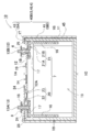
- FIG. 3 is a vertical cross-sectional view of the assembled battery shown in FIG. 2, showing the internal structure of the secondary battery.
- FIG. 5 is a cross-sectional view showing an operating state of a current interruption mechanism of the secondary battery shown in FIG. 4.
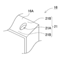
- FIG. 4 is an expansion perspective view which shows the fuse part formed in a current collection member.
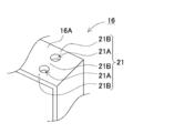
- FIG. 4 is an expansion perspective view which shows another example of a fuse part.
- FIG. 2 is a schematic cross section of the assembled battery according to Embodiment 2 of the present invention.
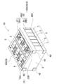
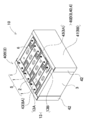
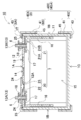
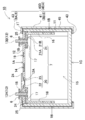
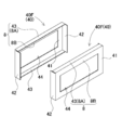
- FIG. 1 It is a vertical cross-sectional view of the assembled battery of FIG. It is a vertical cross-sectional view of the assembled battery according to Embodiment 3 of the present invention. It is a vertical cross-sectional view of the assembled battery according to Embodiment 4 of the present invention. It is a perspective view which shows another example of a fastening member. It is a perspective view which shows another example of a fastening member. It is a schematic cross section showing an example of a current interruption mechanism of a conventional secondary battery.
- the power supply device 100 shown in these drawings shows an example of an in-vehicle power supply device.
- the power supply device 100 is mounted mainly on an electric vehicle such as a hybrid vehicle or an electric vehicle, and is used as a power source for supplying power to the vehicle running motor to drive the vehicle.
- the power supply device of the present invention can be used for an electric vehicle other than a hybrid vehicle or an electric vehicle, and can also be used for an application requiring a high output other than an electric vehicle.
- the external appearance of the power supply device 100 is a box shape whose upper surface is rectangular.
- This power supply device 100 divides a box-shaped outer case 70 and houses a plurality of assembled batteries 10 therein.
- the exterior case 70 includes a lower case 71, an upper case 72, and end plates 73 connected to both ends of the lower case 71 and the upper case 72.
- the end surface plate 73 is connected to both ends of the lower case 71 and the upper case 72 and closes both ends of the exterior case 70.
- the upper case 72 has a flange portion 74 that protrudes outward, and is fixed to the lower case 71 with a bolt and a nut through a screw hole that is open to the flange portion 74. Further, the screw hole of the flange 74 can be used for fixing the power supply device 100. For example, the power supply device 100 is fixed to a vehicle using a screw hole.
- Each assembled battery 10 is fixed at a fixed position inside the outer case 70.
- a total of four battery packs 10 are housed in an outer case 70 in two rows in the longitudinal direction and two rows in the lateral direction.
- the number and layout of the assembled batteries are not limited to this example. For example, it is good also as a structure which accommodates one assembled battery in an exterior case.
- each assembled battery 10 includes a plurality of secondary batteries 1 and a separator 2 that interposes a plurality of secondary batteries 1 on a surface where the secondary batteries 1 are stacked to insulate the secondary batteries 1.
- a pair of end plates 3 disposed on the end surface in the stacking direction of a battery stack 5 in which a plurality of secondary batteries 1 and separators 2 are alternately stacked, and a side plate or an upper surface of the battery stack 5.
- a plurality of metal fastening members 4 for fastening the three together.
- the assembled battery 10 is fixed on the lower case 71.
- the bottom surface of the secondary battery 1 is fixed on the lower case 71 using an adhesive.
- the lower case 71 also serves as a cooling plate for cooling the battery stack 5. That is, by thermally coupling the bottom surface of each secondary battery 1 to the lower case 71, the heat generated by the secondary battery 1 is conducted to the lower case 71 to promote heat dissipation.
- a cooling pipe for circulating the refrigerant may be provided on the lower surface or inside of the lower case 71.
- the separator 2 may be provided with a groove, and the secondary battery 1 may be cooled by flowing a cooling gas through the groove.
- the assembled battery 10 includes a plurality of secondary batteries 1 stacked via an insulating separator 2 to form a battery stack 5, and a pair of end plates 3 disposed on both end faces of the battery stack 5. These end plates 3 are connected by a fastening member 4.
- the assembled battery 10 shown in this figure includes a plurality of secondary batteries 1 and separators 2 by interposing a separator 2 that insulates between adjacent secondary batteries 1 on a laminated surface of the secondary batteries 1. It is set as the battery laminated body 5 laminated
- the assembled battery does not necessarily need to interpose a separator between secondary batteries.
- the secondary battery outer can can be molded with an insulating material such as resin, or the outer periphery of the secondary battery outer can can be covered with a heat-shrinkable tube, insulating sheet, insulating paint, etc.
- a separator can be eliminated.
- a method of cooling the battery stack through a cooling pipe cooled by using a refrigerant or the like is employed, instead of an air cooling method in which cooling air is forced between the secondary batteries to cool the secondary battery. In the configuration, it is not always necessary to interpose a separator between the secondary batteries.
- the secondary battery 1 is a rectangular battery having an outer shape whose thickness is smaller than the width.
- the secondary battery 1 is a chargeable / dischargeable battery such as a lithium ion secondary battery, a nickel hydride secondary battery, or a nickel cadmium secondary battery.
- a lithium ion secondary battery is used for the secondary battery 1, there is an advantage that the charge capacity with respect to the volume and mass of the entire secondary battery can be increased.
- the secondary battery 1 includes an electrode body 15 including a positive electrode and a negative electrode, a bottomed cylindrical outer can 11 having an opening on one surface and housing the electrode body 15, and the outer can 11 is provided with a sealing plate 12 that closes the opening of 11 and a pair of electrode terminals 13 disposed at both ends of the sealing plate 12.
- the electrode body 15 is inserted into the outer can 11 in a state where the positive electrode and the negative electrode are spirally wound with a separator interposed therebetween and then pressed to a predetermined thickness.
- the outer can 11 is a rectangular tube having a closed bottom and a wide surface on both sides facing each other, and opens upward in the figure.
- the outer can 11 having this shape is manufactured by pressing a metal plate such as aluminum or aluminum alloy.
- the opening of the outer can 11 is closed by laser welding with a flat sealing plate 12 obtained by pressing a metal plate.
- the sealing plate 12 is provided with a gas discharge valve 14 between a pair of electrode terminals 13.
- the gas discharge valve 14 is configured to open when the internal pressure of the outer can 11 rises to a predetermined value or more, and to release the internal gas. By opening the gas discharge valve 14, an increase in the internal pressure of the outer can 11 can be suppressed.
- the gas discharge valve 14 is preferably arranged at approximately the center in the longitudinal direction of the sealing plate 12. As a result, even when the adjacent secondary batteries 1 are stacked in a posture reversed in the width direction, the gas discharge valve 14 can always be aligned at the center of the sealing plate 12.
- the sealing plate 12 is provided with a liquid injection part 19 for injecting an electrolytic solution into the outer can 11 adjacent to the gas discharge valve. In the secondary battery 1, the electrode body 15 is inserted into the outer can 11, the opening of the outer can 11 is hermetically sealed with the sealing plate 12, and then an electrolyte solution (not shown) is injected from the liquid injection part 19. Produced.
- the pair of electrode terminals 13 includes a first electrode terminal 13 ⁇ / b> A insulated from the sealing plate 12 and a second electrode terminal 13 ⁇ / b> B electrically connected to the sealing plate 12.
- the pair of electrode terminals 13 are fixed to a fixed position of the sealing plate 12 via a gasket 17.
- the first electrode terminal 13 ⁇ / b> A is connected to the sealing plate 12 through the gasket 17 in an insulated state.
- the second electrode terminal 13B is connected to the sealing plate 12 via the gasket 17 and sealed on the upper surface side of the sealing plate 12 via a metal fixing member 18 fixed to the second electrode terminal 13B. It is electrically connected to the plate 12.
- the positive and negative electrode terminals 13 fixed to the sealing plate 12 are electrically connected to the electrode body 15 via the current collecting member 16 inside the secondary battery 1.
- the secondary battery 1 uses the second electrode terminal 13B connected to the sealing plate 12 and the outer can 11 as a positive electrode terminal, and the first electrode terminal 13A as a negative electrode terminal.
- the secondary battery 1 responds to an increase in internal pressure inside the outer can 11 and interrupts the electrical connection between the electrode body 15 and the second electrode terminal 13B. 7 is provided.
- the current interruption mechanism 7 shown in the figure is connected to the second electrode terminal 13B and the short-circuit portion 20 that short-circuits the first electrode terminal 13A and the sealing plate 12 when the internal pressure of the secondary battery 1 becomes higher than the set pressure.
- a fuse portion 21 provided on the current collecting member 16.
- the current interruption mechanism 7 is configured such that the fuse part 21 is blown by the overcurrent flowing through the fuse part 21 in a state where the internal pressure of the battery is higher than the set pressure and the short-circuit part 20 is short-circuited. The electrical connection of the electrode terminal 13B is cut off to interrupt the current.
- Short-circuit part 20 When the internal pressure of the secondary battery 1 becomes higher than the set pressure due to overcharging or the like, the short-circuit unit 20 functions so as to induce a short circuit and a large current flows through the fuse unit 21.
- 3 includes a reversing plate 22 made of a conductive material fixed to the sealing plate 12 and a metal connection plate 23 disposed on the upper surface side of the sealing plate 12 so as to face the reversing plate 22. I have.
- the reversing plate 22 As shown in FIG. 4, the reversing plate 22 is provided in the short-circuit hole 12 ⁇ / b> A opened in the sealing plate 12 by a method such as welding.
- the reversing plate 22 has an outer peripheral edge portion that is electrically connected to the sealing plate 12, and a central portion that is bent in a posture that protrudes toward the inside of the outer can 11.
- the reversing plate 22 is reversed and swollen upward as shown in FIG. A short circuit is induced by protruding in the direction of leaving and contacting the connection plate 23.
- the inversion board 22 is made into one sheet, a plurality of inversion boards can also be laminated.
- the short-circuit part provided by laminating a plurality of reversing plates provides a difference in the thickness of each reversing plate and the set pressure to be reversed, so that one of the reversing plates reacts more smoothly to the increase in internal pressure in the battery. Even if the reversal plate is melted by heat, the short circuit can be maintained in the other reversal plate so that the fuse function of the fuse portion can continue to act.
- connection plate 23 is disposed on the upper surface of the sealing plate 12 via the insulating portion 24 and is connected to the sealing plate 12 in an insulated state.
- the connection plate 23 is electrically connected to the first electrode terminal 13A.
- the first electrode terminal 13A is inserted into a hole opened in a part of the connection plate 23, and the fixing member 18 fixed to the first electrode terminal 13A on the upper surface side of the connection plate 23 is provided.
- the connection plate 23 and the first electrode terminal 13A are electrically connected.
- the fuse portion 21 is a portion that is melted and cut by heat generated by an overcurrent flowing in the battery in the short-circuit state of the short-circuit portion 20, and is provided in a current conduction path during a short-circuit.
- the fuse portion 21 shown in FIG. 3 is provided in the current collecting member 16 connected to the second electrode terminal 13B.
- the fuse portion 21 formed on the current collecting member 16 is configured to be blown by an overcurrent flowing through the current collecting member 16 in a short circuit state of the short circuit portion 20.
- the fuse portion 21 shown in FIG. 3 is formed by a fuse hole 21A opened in the current collecting member 16. Specifically, as shown in FIG. 6, the fuse portion 21 is opened in the plate-like portion 16A in the current collecting member 16.
- the connecting portion 21B is formed on both sides of the fuse hole 21A.
- the connection portion 21B is a portion whose cross-sectional area becomes small due to the opening of the fuse hole 21A, and is melted by heat generated by a large current flowing when the secondary battery 1 is short-circuited due to local increase in electrical resistance. Functions as a fuse that cuts off current.
- the current collecting member 16 shown in FIG. 6 has one fuse hole 21A opened in the plate-like portion 16A, and the connecting portions 21B are formed on both sides thereof. However, as shown in FIG.
- the current collecting member 16 has a plurality of (two in FIG. 7) fuse holes 21A in the plate-like portion 16A, and connecting portions between them and on both sides of the plate-like portion 16A.
- 21B can also be formed.
- the planar shape of the fuse hole 21A is an ellipse or a circle.
- the fuse hole 21A has an oval shape, a rectangular shape, a polygonal shape, an arc shape, a slit shape, or the like. Can be variously changed.
- the fuse portion is provided with notches on both sides of the plate-like portion, and a narrow portion formed in the central portion can be used as a connecting portion, or a notch can be formed on one side of the plate-like portion.
- the other remaining side part is used as a connection part, or a notch part is provided in the side part of the plate-like part and a fuse hole is provided in the center part to provide a narrow part as a connection part. You can also.
- the connection part 21B is melted and cut in the region where the fuse hole 21A and the cutout part are formed, so that the plate-like part 16A of the current collecting member 16 is electrically separated and the current flows. Shut off.
- the fuse portion 21 is disposed in a region above the electrode body 15 accommodated in the outer can 11 and outside the electrode terminal 13. That is, the fuse portion 21 is disposed close to the upper end corner portion 1T that is a boundary portion between the upper surface and the side surface of the secondary battery 1.
- the fuse part 21 is preferably formed by providing an opening in the plate-like part 16 ⁇ / b> A of the current collecting member 16. Moreover, it is preferable that the thickness of the sealing plate 12 is set to be twice or more the thickness of the plate-like portion 16 ⁇ / b> A of the current collecting member 16.
- the electric current interruption mechanism 7 shown in FIG. 3 has provided the fuse part 21 in the current collection member 16 connected to the 2nd electrode terminal 13B.
- This structure is characterized in that the short-circuit portion 20 and the fuse portion 21 are arranged apart from each other, thereby reducing adverse effects on the short-circuit portion 20 due to sparks generated when the fuse portion 21 is blown or re-conducted.
- the fuse portion can also be provided in the current collecting member connected to the first electrode terminal.
- the secondary battery 1 is stacked in such a manner that the wide surfaces as the main surface 1X face each other, and the upper surface 1A and the side surface 1B are stacked so as to be in the same plane. It becomes the body 5.
- the plurality of secondary batteries 1 that are stacked on each other and constitute the battery stack 5 are connected in series by connecting adjacent positive and negative electrode terminals 13 with a bus bar 6.
- the assembled battery 10 in which the adjacent secondary batteries 1 are connected in series can increase the output voltage and increase the output.
- the assembled battery can connect adjacent secondary batteries in parallel, or can be connected in multiple-multiple by combining series connection and parallel connection.
- the assembled battery 10 in which the secondary batteries 1 are connected in series has a posture in which the positive and negative electrode terminals 13 are adjacent to each other in the adjacent secondary batteries 1, in other words, The secondary batteries 1 are stacked in a posture that is alternately reversed left and right. Thereby, the bus bar 6 connecting the electrode terminals 13 can be reduced in size.
- the position of the fuse part 21 incorporated in the secondary battery 1 will also be arrange
- the secondary battery 1 is manufactured with a metal outer can 11.
- an insulating separator 2 is sandwiched between the secondary batteries 1 to prevent a short circuit with the outer can 11 of the adjacent secondary battery 1.
- the separator 2 is a spacer for insulating and laminating adjacent secondary batteries 1 electrically and thermally.
- the separator 2 is made of an insulating material such as resin and is disposed between the adjacent secondary batteries 1 to insulate the adjacent secondary batteries 1.
- End plate 3 A pair of end plates 3 are arranged on both end faces of the battery stack 5 in which the secondary battery 1 and the separator 2 are alternately stacked, and the battery stack 5 is fastened by the pair of end plates 3.
- the end plate 3 is made of a material that exhibits sufficient strength, for example, metal.
- the end plate 3 has a fixing structure for fixing to the lower case 71 shown in FIG.
- the end plate may be made of a resin material, or the resin end plate may be reinforced with a member made of a metal material.
- the fastening member 4 As shown in FIGS. 2 to 5, the fastening member 4 is disposed on the side surface or the upper surface of the battery stack 5 in which the end plates 3 are stacked at both ends, and both ends are fixed to the pair of end plates 3. Then, the battery stack 5 is fastened.
- the fastening member 4 shown in the figure is a bind bar 40 formed by bending a metal plate having a predetermined thickness and processing it into a predetermined shape.
- a material having sufficient strength for example, a metal plate such as iron, preferably a steel plate can be used. Thus, it can comprise at low cost by using as the fastening member 4 the bind bar 40 which bent the metal plate.
- the fastening member 4 which is the bind bar 40 is extended in the stacking direction of the battery stack 5, and both ends are fixed to the pair of end plates 3.
- the bind bar 40 includes a main body portion 41 disposed along the side surface of the battery stack 5 and connecting pieces 42 provided at both ends of the main body portion 41 and fixed to the end plate 3.
- the bind bar 40A shown in FIGS. 2 to 5 is arranged to face the upper and lower portions of both side surfaces of the battery stack 5 and the end plate 3. That is, the pair of end plates 3 are fastened through the four bind bars 40A.
- the four bind bars 40 ⁇ / b> A include two upper bind bars 40 ⁇ / b> X disposed at the upper part of the side surface of the battery stack 5 and two lower bind bars 40 ⁇ / b> Y disposed at the lower part of the side surface of the battery stack 5. I have.
- the upper binding bar 40X is provided with connecting pieces 42 at both ends of the main body 41 having a predetermined width, and a horizontal portion 43 that covers the upper surface of the battery stack 5 is provided at the upper end of the main body 41, and the crossing thereof.
- the surface shape is L-shaped.
- the upper bind bar 40 ⁇ / b> X shown in FIG. 4 extends the main body portion 41 upward, and the extension portion is bent toward the upper surface side of the battery stack 5 to provide a horizontal portion 43.
- the horizontal portion 43 is bent substantially perpendicular to the main body portion 41 so as to have a horizontal posture along the upper surface of the secondary battery 1.
- the upper bind bar 40 ⁇ / b> X uses the horizontal portion 43 as a holding portion that holds the upper surface of the battery stack 5.
- the lower binding bar 40Y is provided with connecting pieces 42 at both ends of a main body 41 having a predetermined width.
- the connecting pieces 42 provided at both ends of the main body 41 are bent at a right angle with respect to the main body 41 so as to contact the outer surface of the end plate 3 in a surface contact state.
- both ends of the bind bar 40 are fixed to the end plate 3 via a connecting tool such as a set screw, or fixed to the end plate 3 with a locking structure, or are attached to the end plate 3 by adhesion or welding.
- the binding bar 40 shown in FIGS. 2 and 3 has a connecting piece 42 that is bent at both ends, and can be fixed to the outer surface of the end plate 3 via the connecting piece 42.
- the bind bar does not necessarily need to be provided with connecting pieces at both ends.
- a binding bar without a connecting piece can be fixed by, for example, screwing a connecting tool such as a set screw penetrating both ends into the side surface of the end plate, or by penetrating the end plate vertically or horizontally. This structure can shorten the total length of the assembled battery.
- the fastening member 4 includes a protective cover portion 8 that covers an upper end corner portion 1T that is a boundary between the upper surface 1A and the side surface 1B of the secondary battery 1.
- the protective cover 8 is an upper end corner 1T of the secondary battery 1 and is disposed so as to cover a corner close to the fuse portion 21 built in the outer can 11.
- the fuse part 21 is provided in the current collecting member 16 that connects the second electrode terminal 13 ⁇ / b> B and the electrode body 15 disposed at the end of the sealing plate 12. It is an edge on the side where the electrode terminal 13B is disposed, and is disposed so as to cover a connection portion between the sealing plate 12 and the outer can 11.
- the upper bind bar 40X is also used as the protective cover portion 8.
- the upper bind bar 40X shown in FIG. 4 uses the main body 41 that covers the upper part of the side surface of the battery stack 5 as the side cover 8B of the protective cover 8, and the horizontal part 43 that covers the upper surface of the battery stack 5. Is functioning as the upper surface cover portion 8A of the protective cover portion 8.
- the protective cover portion 8 has a shape that can cover the area including the welded portion 25 between at least the opening of the outer can 11 and the edge of the sealing plate 12 in the vicinity of the upper end corner portion 1T of the secondary battery 1.
- the boundary portion is welded at the opening of the outer can 11 so that the outer peripheral edge of the sealing plate 12 is fitted inside the opening edge. Therefore, in the secondary battery 1, the welded portion 25 between the outer can 11 and the sealing plate 12 is provided on the upper surface of the secondary battery 1.
- the length (S) in the width direction of the secondary battery 1 in which the upper surface cover portion 8A covers the upper surface of the upper end corner portion 1T is larger than the thickness of the outer can 11 and is 2 mm or more, preferably 5 mm or more.
- the length (H) in the vertical direction in which the side cover portion 8B covers the side surface of the upper end corner portion 1T is 1 cm or more, preferably 3 cm or more.
- the welded portion is not necessarily formed on the upper surface side.
- the boundary portion can be welded in the state where the outer peripheral edge of the sealing plate is brought into contact with the opening edge at the opening of the outer can.
- the welded portion between the outer can and the sealing plate is provided on the outer peripheral surface (side surface and main surface) of the secondary battery along the outer peripheral edge of the sealing plate.
- the secondary battery having this structure is a side cover portion that covers the side surface of the upper end corner portion, and covers a weld portion formed outside the opening edge of the outer can.
- the adjacent secondary batteries 1 are connected to each other. They are stacked in a posture that is alternately reversed left and right. For this reason, the positions of the fuse portions 21 incorporated in the secondary battery 1 are also alternately different between adjacent secondary batteries 1. Therefore, in this assembled battery 10, as shown in FIGS. 2 to 4, protective cover portions 8 that are located on both sides of the battery stack 5 and cover the upper corner portion 1T of the secondary battery 1 are arranged.
- any secondary battery 1 the upper end corner portion 1 ⁇ / b> T close to the fuse portion 21 is covered with the protective cover portion 8, and even if a spark is generated in the battery, it is outside the battery. It is possible to improve safety by suppressing the sparks from being scattered by the protective cover 8.
- the assembled battery 10 shown in FIG. 4 is provided with an insulating member 45 on the inner surface of the bind bar 40.
- the insulating member 45 is for insulating the metal binding bar 40 and the outer can 11 of the secondary battery 1, and an insulating sheet, an insulating plate, an insulating paint, or the like can be used.
- the insulating member 45 disposed on the inner surface of the protective cover 8 it is possible to reduce damage and harmful effects due to sparks, preferably by using a sheet material or a plate material made of a heat-resistant or flame-retardant resin.
- the insulating member 45 is preferably provided on the entire inner surface of the bind bar 40 and insulates the surface facing the battery stack 5.
- the assembled battery 10 shown in the drawing is provided with insulating members 45 on the inner surface of the upper bind bar 40X and the inner surface of the lower bind bar 40Y, respectively.
- a part of the separator 2 disposed between the secondary batteries 1 can also serve as the insulating member 45.
- the insulating member provided on the inner surface of the bind bar is omitted. You can also.
- the fastening member 4 is composed of four bind bars 40A, and the upper bind bar 40X fastens the upper side of the battery stack 5 and the lower bind bar 40Y fastens the lower part of the battery stack 5. did.
- the gap between the upper bind bar and the lower bind bar is used as a ventilation part.
- the cooling air can be passed and blown.
- the fastening members 4 arranged on both sides of the battery stack 5 can also be configured by a single bind bar 40B.
- the assembled battery 10 shown in FIGS. 8 and 9 has a structure in which the bind bar 40B includes a main body portion 41 that faces the side surface of the battery stack 5 and the main body portion 41 covers the entire side surface of the battery stack 5. Yes.
- the bind bar 40B shown in the figure is provided with connecting pieces 42 at both ends of a main body 41 having a width capable of covering the entire side surface of the battery stack 5, and covers the upper surface of the battery stack 5 at the upper end of the main body 41.
- the horizontal portion 43 is provided, and the cross-sectional shape thereof is L-shaped.
- the bind bar 40B is also used as the protective cover portion 8 that covers the upper end corner portion 1T of the secondary battery 1.
- the main body portion 41 that covers the upper part of the side surface of the battery stack 5 is used as the side cover portion 8B of the protective cover portion 8, and the horizontal portion 43 that covers the upper surface of the battery stack 5 is the upper surface cover portion 8A of the protective cover portion 8. It is functioning as.
- the bind bar 40B is provided with an insulating member 45 on the entire inner surface to cover the entire side surface of the battery stack 5 and both end portions of the upper surface.
- the bind bar 40 ⁇ / b> B having this structure can broaden the main body 41 facing the side surface of the battery stack 5 to improve the mechanical strength, and covers the entire side surface of the battery stack 5. It is possible to reliably prevent the sparks from being scattered on the side surface of 5.
- the fastening member 4 may be structured to cover at least a part of the bottom surface of the battery stack 5.
- the fastening member 4 can cover the corner portion on the bottom surface side of the battery stack 5 by providing the horizontal portion 43 at the lower end of the bind bar 40.
- the bind bar 40C shown in FIG. 10 includes two upper bind bars 40X disposed at the corners on the upper surface side of the battery stack 5 and two lower bind bars 40X disposed at the corners on the lower surface side of the battery stack 5. And a bind bar 40Y. Similar to the upper bind bar 40X described above, the upper bind bar 40X is provided with connecting pieces 42 at both ends of the main body 41 having a predetermined width, and the upper end of the main body 41 covers the upper surface of the battery stack 5. The horizontal portion 43 is provided, and the cross-sectional shape thereof is L-shaped. The upper bind bar 40X is also used as the protective cover portion 8.
- the lower binding bar 40Z is provided with connecting pieces 42 at both ends of the main body 41 having a predetermined width, and at the lower end of the main body 41, a horizontal portion 43 that covers the bottom surface of the battery stack 5 is provided.
- the cross-sectional shape is L-shaped.
- the horizontal portion 43 is bent substantially perpendicular to the main body portion 41 so as to have a horizontal posture along the bottom surface 1 ⁇ / b> C of the secondary battery 1.
- the four bind bars 4C arranged at the four corners of the battery stack 5 have the main body 41 on both sides of the battery stack 5 to prevent the secondary battery 1 from moving in the horizontal direction, and the horizontal portion 43. Is above and below the battery stack 5 and prevents the secondary battery 1 from moving in the vertical direction.
- a bind bar 40D shown in FIG. 11 is provided with a horizontal portion 43 that covers the upper and lower surfaces of the battery stack 5 at the upper and lower ends of the main body 41 that covers the entire side surface of the battery stack 5, respectively.
- the shape is U-shaped.
- the bind bar 40D constitutes a protective cover portion 8 that covers the upper end corner portion 1T of the secondary battery 1 with the main body portion 41 and the horizontal portion 43 provided at the upper end thereof. That is, the main body portion 41 that covers the side surface of the battery stack 5 functions as the side cover portion 8B of the protective cover portion 8, and the horizontal portion 43 that covers the upper surface of the battery stack 5 functions as the upper surface cover portion 8A of the protective cover portion 8. I am letting.
- the bind bar 40 ⁇ / b> D having this structure can broaden the body 41 facing the side surface of the battery stack 5 to improve the mechanical strength, and covers the entire side surface of the battery stack 5. It is possible to reliably prevent the sparks from being scattered on the side surface of 5.
- the binding bar 40D having a U-shaped cross-sectional view disposed on both side surfaces of the battery stack 5 has the main body portion 41 on both sides of the battery stack 5 and prevents the secondary battery 1 from moving in the horizontal direction.
- the horizontal portion 43 is located above and below the battery stack 5 to prevent the secondary battery 1 from moving in the vertical direction.
- the fastening member 4 can also be provided with an opening window in the main body 41 that covers the side surface of the battery stack 5.
- the binding bars 40E and 40F shown in FIGS. 12 and 13 are provided with an opening window 44 at the center of the main body 41 that covers the side surface of the battery stack 5.
- the opening window 44 shown in the figure is opened to face an intermediate portion excluding the upper part and the lower part of the side surface of the battery stack 5.
- the bind bar 40E of FIG. 10 is provided with connecting pieces 42 at both ends of a main body 41 having an opening window 44 in the center, and a horizontal portion 43 that covers the upper surface of the battery stack at the upper end of the main body 41. ing.
- the bind bar 40 ⁇ / b> E has a main body portion 41 having a frame shape, and the upper portion of the main body portion 41 and the horizontal portion 43 function as a protective cover portion 8 that covers the upper end corner portion 1 ⁇ / b> T of the secondary battery 1.
- the bind bar 40F of FIG. 11 is provided with connecting pieces 42 at both ends of a main body 41 having an opening window 44 in the center, and covers the upper and lower ends of the battery stack at the upper and lower ends of the main body 41.
- Each horizontal portion 43 is provided.
- the bind bar 40F also has a main body 41 having a frame shape, and has the upper portion of the main body 41 and the horizontal portion 43 at the upper end function as a protective cover portion 8 that covers the upper end corner portion 1T of the secondary battery 1. Yes.
- bind bars 40E and 40F are provided with an opening window 44, so that the bind bars 40E and 40F are reduced in weight while being reduced in weight. Furthermore, the side surface of the battery stack is exposed from the opening window 44 so that the secondary battery can efficiently dissipate heat.
- the cooling air is supplied to the opening window through the opening window provided in the bind bar. The air can be blown through.
- the above power supply devices can be used as in-vehicle power supplies.
- a vehicle equipped with a power supply device an electric vehicle such as a hybrid vehicle or a plug-in hybrid vehicle that runs with both an engine and a motor, or an electric vehicle that runs only with a motor can be used, and is used as a power source for these vehicles. .
- each element constituting the present invention may be configured such that a plurality of elements are constituted by the same member and the plurality of elements are shared by one member, and conversely, the function of one member is constituted by a plurality of members. It can also be realized by sharing.
- the power supply device according to the present invention and a vehicle including the power supply device can be suitably used as a power supply device for a plug-in hybrid electric vehicle, a hybrid electric vehicle, an electric vehicle, or the like that can switch between the EV traveling mode and the HEV traveling mode.
- a backup power supply device that can be mounted on a rack of a computer server, a backup power supply device for a wireless base station such as a mobile phone, a power storage device for home use and a factory, a power supply for a street light, etc. Also, it can be used as appropriate for applications such as a backup power source such as a traffic light.
- SYMBOLS 100 Power supply device 1 ... Secondary battery 1A ... Upper surface 1B ... Side surface 1C ... Bottom surface 1X ... Main surface 1T ... Upper end corner part 2 ... Separator 3 ... End plate 4 ... Fastening member 5 ... Battery laminated body 6 ... Bus bar 7 ... Current interruption Mechanism 8 ... Protective cover portion 8A ... Top cover portion 8B ... Side cover portion 10 ... Battery 11 ... Exterior can 12 ... Sealing plate 12A ... Short hole 13 ... Electrode terminal 13A ... First electrode terminal 13B ... Second electrode terminal DESCRIPTION OF SYMBOLS 14 ... Gas exhaust valve 15 ... Electrode body 16 ... Current collecting member 16A ... Plate-shaped part 17 ...
Landscapes
- Chemical & Material Sciences (AREA)
- General Chemical & Material Sciences (AREA)
- Electrochemistry (AREA)
- Chemical Kinetics & Catalysis (AREA)
- Engineering & Computer Science (AREA)
- Sustainable Energy (AREA)
- Mechanical Engineering (AREA)
- Aviation & Aerospace Engineering (AREA)
- Transportation (AREA)
- Power Engineering (AREA)
- Life Sciences & Earth Sciences (AREA)
- Sustainable Development (AREA)
- Connection Of Batteries Or Terminals (AREA)
- Battery Mounting, Suspending (AREA)
Abstract
Description
なお、本明細書において二次電池の上下方向は、図において特定するものとする。また、二次電池の側面とは、幅広面である主面を互いに対向させて複数の二次電池を積層して電池積層体とする状態で、電池積層体の両側に配置される幅狭面を意味している。
本発明の実施形態1に係る電源装置100を、図1~図5に示す。これらの図に示す電源装置100は、車載用の電源装置の例を示している。具体的には、この電源装置100は、主としてハイブリッド車や電気自動車等の電動車両に搭載されて、車両の走行モータに電力を供給して、車両を走行させる電源に使用される。ただ、本発明の電源装置は、ハイブリッド車や電気自動車以外の電動車両に使用でき、また電動車両以外の大出力が要求される用途にも使用できる。
電源装置100の外観は、図1の分解斜視図に示すように、上面を長方形状とする箱形である。この電源装置100は、箱形の外装ケース70を分割して、内部に複数の組電池10を収納している。外装ケース70は、下ケース71と、上ケース72と、これらの下ケース71、上ケース72の両端に連結している端面プレート73とを備えている。端面プレート73は、下ケース71と上ケース72の両端に連結されて、外装ケース70の両端を閉塞している。上ケース72は、外側に突出する鍔部74を有し、この鍔部74に開口したねじ穴でもって下ケース71にボルトとナットで固定している。さらに鍔部74のねじ穴を、電源装置100の固定にも利用できる。例えば電源装置100を固定する車両に、ねじ穴を利用してねじ止めする。
各組電池10は、図2と図3に示すように、複数の二次電池1と、複数の二次電池1同士を積層する面に介在させて、二次電池1間を絶縁するセパレータ2と、複数の二次電池1とセパレータ2を交互に積層した電池積層体5の積層方向の端面に配置された一対のエンドプレート3と、電池積層体5の側面ないし上面に配置され、エンドプレート3同士を締結する金属製の複数の締結部材4とを備えている。さらに組電池10は、下ケース71上に固定されている。例えば下ケース71上に、接着剤を用いて二次電池1の底面を接着により固定する。
組電池10は、複数の二次電池1を、絶縁性のセパレータ2を介して積層して電池積層体5とし、この電池積層体5の両端面に一対のエンドプレート3を配置して、一対のエンドプレート3を締結部材4で連結している。この図に示す組電池10は、互いに隣接する二次電池1同士の間を絶縁するセパレータ2を、二次電池1同士の積層面に介在させて、複数の二次電池1とセパレータ2とを交互に積層した電池積層体5としている。
二次電池1は、図3に示すように、幅よりも厚さを小さくした外形の角形電池としている。二次電池1は、リチウムイオン二次電池、ニッケル水素二次電池、ニッケルカドミウム二次電池等の充放電可能な電池である。特に、二次電池1にリチウムイオン二次電池を使用すると、二次電池全体の体積や質量に対する充電容量を大きくできる特長がある。
二次電池1は、過充電等による熱暴走を回避するため、外装缶11の内部の内圧の上昇に反応して電極体15と第2の電極端子13Bの電気的接続を遮断する電流遮断機構7を備えている。図に示す電流遮断機構7は、二次電池1の内圧が設定圧力よりも高くなると第1の電極端子13Aと封口板12とを短絡させる短絡部20と、第2の電極端子13Bに接続された集電部材16に設けられたヒューズ部21とを備えている。この電流遮断機構7は、電池の内圧が設定圧力よりも高くなって短絡部20が短絡する状態で、ヒューズ部21に流れる過電流によってヒューズ部21が溶断されることにより電極体15と第2の電極端子13Bの電気的接続が切断されて、電流を遮断する。
短絡部20は、過充電などにより二次電池1の内部圧力が設定圧力より高くなると、短絡を誘導してヒューズ部21に大電流が流れるように機能する。図3の短絡部20は、封口板12に固定された導電性材料からなる反転板22と、反転板22に対向して封口板12の上面側に配置された金属製の接続プレート23とを備えている。
反転板22は、図4に示すように、溶接などの方法により封口板12に開口された短絡孔12Aに設けられている。この反転板22は、外周縁部が封口板12に電気的に接続されており、中央部が外装缶11の内部に向かって突出する姿勢で湾曲されている。反転板22は、二次電池1に過充電が発生して二次電池1の内部圧力が設定圧力より高くなると、図5に示すように反転されて上に膨らんで、すなわち、電極体15から離れる方向に突出し、接続プレート23に接触することで短絡を誘発させる。
ヒューズ部21は、短絡部20の短絡状態において、電池内に流れる過電流によって生じる熱で溶融されて切断される部位であって、短絡時における電流の導通経路に設けられている。図3に示すヒューズ部21は、第2の電極端子13Bに接続された集電部材16に設けている。集電部材16に形成されるヒューズ部21は、短絡部20の短絡状態において、集電部材16に流れる過電流で溶断される構成としている。
二次電池1は、金属製の外装缶11で製作している。この二次電池1は、隣接する二次電池1の外装缶11との短絡を防止するため、絶縁性のセパレータ2を挟着している。セパレータ2は、隣接する二次電池1を電気的、熱的に絶縁して積層するためのスペーサである。このセパレータ2は樹脂等の絶縁材で製作しており、互いに隣接する二次電池1同士の間に配置されて、隣接する二次電池1を絶縁している。
二次電池1とセパレータ2とを交互に積層した電池積層体5の両端面には一対のエンドプレート3を配置して、一対のエンドプレート3で電池積層体5を締結している。エンドプレート3は、十分な強度を発揮する材質、例えば金属製とする。このエンドプレート3は、図1に示す下ケース71と固定するための固定構造を備えている。ただ、エンドプレートは、材質を樹脂製とすることや、さらに、この樹脂製のエンドプレートを金属製の材質からなる部材で補強して構成しても良い。
締結部材4は、図2~図5に示すに示すように、両端にエンドプレート3が積層された電池積層体5の側面ないし上面に配置されると共に、両端が一対のエンドプレート3に固定されて電池積層体5を締結する。図に示す締結部材4は、所定の厚さを有する金属板を折曲して所定の形状に加工してなるバインドバー40としている。このようなバインドバー40は、十分な強度を有する材質、例えば鉄などの金属板、好ましくは、鋼板が使用できる。このように、金属板を折曲したバインドバー40を締結部材4とすることで、安価に構成できる。
さらに、図4に示す組電池10は、バインドバー40の内面に、絶縁部材45を設けている。この絶縁部材45は、金属製のバインドバー40と二次電池1の外装缶11とを絶縁するためのもので、絶縁シートや絶縁プレート、絶縁塗料等が使用できる。とくに、保護カバー部8の内面に配置される絶縁部材45については、好ましくは耐熱性や難燃性の樹脂からなるシート材やプレート材を使用することでスパークによる破損や弊害を低減できる。絶縁部材45は、好ましくはバインドバー40の内面の全面に設けて、電池積層体5との対向面を絶縁する。図に示す組電池10は、上バインドバー40Xの内面と下バインドバー40Yの内面にそれぞれ絶縁部材45を設けている。なお、二次電池1間に配置されるセパレータ2の一部が絶縁部材45を兼ねるようにすることもできる。また、前述のように、外装缶及び封口板の表面が熱収縮チューブや絶縁シート、絶縁塗料等で被覆されて絶縁されてなる二次電池においては、バインドバーの内面に設ける絶縁部材を省略することもできる。
図8と図9に示す組電池10は、バインドバー40Bが、電池積層体5の側面に対向する本体部41を備えており、本体部41で電池積層体5の側面全体を被覆する構造としている。図のバインドバー40Bは、電池積層体5の側面全体を被覆可能な幅を有する本体部41の両端に連結片42を設けると共に、本体部41の上端には、電池積層体5の上面をカバーする水平部43を設けて、その横断面形状をL字状としている。このバインドバー40Bも、二次電池1の上端コーナー部1Tをカバーする保護カバー部8に兼用している。すなわち、電池積層体5の側面の上部をカバーする本体部41を保護カバー部8の側面カバー部8Bとし、電池積層体5の上面をカバーする水平部43を保護カバー部8の上面カバー部8Aとして機能させている。さらに、バインドバー40Bは、内面の全面に絶縁部材45を設けて、電池積層体5の側面全体と上面の両端部を被覆している。この構造のバインドバー40Bは、電池積層体5の側面に対向する本体部41を幅広に形成して機械的強度を向上できると共に、電池積層体5の側面全体を被覆することで、電池積層体5の側面側へのスパークの飛散を確実に阻止できる。
図10に示すバインドバー40Cは、電池積層体5の上面側の隅部に配置される2本の上バインドバー40Xと、電池積層体5の下面側の隅部に配置される2本の下バインドバー40Yとを備えている。上バインドバー40Xは、前述の上バインドバー40Xと同様に、所定の幅を有する本体部41の両端に連結片42を設けると共に、本体部41の上端には、電池積層体5の上面をカバーする水平部43を設けて、その横断面形状をL字状としている。この上バインドバー40Xは、保護カバー部8に兼用している。また、下バインドバー40Zは、所定の幅を有する本体部41の両端に連結片42を設けると共に、本体部41の下端には、電池積層体5の底面をカバーする水平部43を設けて、その横断面形状をL字状としている。この水平部43は、二次電池1の底面1Cに沿う水平な姿勢となるように、本体部41に対して略垂直に折曲されている。電池積層体5の四隅部に配置される4本のバインドバー4Cは、本体部41が電池積層体5の両側にあって、二次電池1の水平方向の移動を阻止すると共に、水平部43が電池積層体5の上下にあって、二次電池1の上下方向の移動を阻止している。
図11に示すバインドバー40Dは、電池積層体5の側面全体を被覆する本体部41の上端と下端に、電池積層体5の上面と下面をカバーする水平部43をそれぞれ設けて、その横断面形状をコ字状としている。このバインドバー40Dは、本体部41とその上端に設けた水平部43とで二次電池1の上端コーナー部1Tをカバーする保護カバー部8を構成している。すなわち、電池積層体5の側面をカバーする本体部41を保護カバー部8の側面カバー部8Bとし、電池積層体5の上面をカバーする水平部43を保護カバー部8の上面カバー部8Aとして機能させている。この構造のバインドバー40Dは、電池積層体5の側面に対向する本体部41を幅広に形成して機械的強度を向上できると共に、電池積層体5の側面全体を被覆することで、電池積層体5の側面側へのスパークの飛散を確実に阻止できる。また、電池積層体5の両側面に配置される断面視コ字状のバインドバー40Dは、本体部41が電池積層体5の両側にあって、二次電池1の水平方向の移動を阻止すると共に、水平部43が電池積層体5の上下にあって、二次電池1の上下方向の移動を阻止している。
さらに、締結部材4は、電池積層体5の側面をカバーする本体部41に開口窓を設けることもできる。図12と図13に示すバインドバー40E、40Fは、電池積層体5の側面をカバーする本体部41の中央部に開口窓44を設けている。図に示す開口窓44は、電池積層体5の側面の上部と下部を除く中間部に対向して開口されている。
1…二次電池
1A…上面
1B…側面
1C…底面
1X…主面
1T…上端コーナー部
2…セパレータ
3…エンドプレート
4…締結部材
5…電池積層体
6…バスバー
7…電流遮断機構
8…保護カバー部
8A…上面カバー部
8B…側面カバー部
10…組電池
11…外装缶
12…封口板
12A…短絡孔
13…電極端子
13A…第1の電極端子
13B…第2の電極端子
14…ガス排出弁
15…電極体
16…集電部材
16A…板状部
17…ガスケット
18…固定部材
19…注液部
20…短絡部
21…ヒューズ部
21A…ヒューズ孔
21B…接続部
22…反転板
23…接続プレート
24…絶縁部
25…溶着部
45…絶縁部材
40、40A、40B、40C、40D、40E、40F…バインドバー
40X…上バインドバー
40Y、40Z…下バインドバー
41…本体部
42…連結片
43…水平部
44…開口窓
45…絶縁部材
70…外装ケース
71…下ケース
72…上ケース
73…端面プレート
74…鍔部
101…二次電池
111…外装缶
112…封口板
115…電極体
116…集電板
121…ヒューズ部
122…反転板
123…接続プレート
124…絶縁部材
Claims (8)
- 複数の二次電池を積層した電池積層体と、
前記電池積層体を締結する締結部材と
を備える電源装置であって、
前記二次電池は、
正極及び負極を含む電極体と、
開口部を有し、前記電極体を収納する有底筒状の外装缶と、
前記外装缶の開口部を閉塞する封口板と、
前記封口板に配置された一対の電極端子と、
電流遮断機構と
を備えており、
前記一対の電極端子は、前記封口板から絶縁された第1の電極端子と、前記封口板に電気接続された第2の電極端子とを備え、該二次電池の内部において、集電部材を介して前記電極体に電気接続されており、
前記電流遮断機構は、該二次電池の内圧が設定圧力よりも大きくなると前記第1の電極端子と前記封口板とを短絡させる短絡部と、前記集電部材に設けられたヒューズ部とを備えており、
前記ヒューズ部は、前記二次電池の上面と側面との境界部である上端コーナー部に接近して配置されると共に、前記短絡部の短絡状態において、過電流で溶断される構成としており、
前記締結部材は、前記電池積層体の両側に位置して前記二次電池の前記上端コーナー部をカバーする保護カバー部を備えており、
前記保護カバー部は、前記上端コーナー部の上面をカバーする上面カバー部と前記上端コーナー部の側面をカバーする側面カバー部とを備える電源装置。 - 請求項1に記載の電源装置であって、
前記締結部材が、所定の厚さの金属板を折曲加工してなるバインドバーである電源装置。 - 請求項2に記載の電源装置であって、
前記バインドバーの内面に、絶縁部材が設けられた電源装置。 - 請求項2または3に記載の電源装置であって、
前記バインドバーが、前記電池積層体の側面の上部をカバーする上バインバーと、前記電池積層体の側面の下部をカバーする下バインドバーとを備えており、
前記上バインドバーが前記保護カバー部を兼ねる電源装置。 - 請求項2または3に記載の電源装置であって、
前記バインドバーが、前記電池積層体の側面に対向する本体部を備えており、前記本体部で前記電池積層体の側面全体を被覆する電源装置。 - 請求項2または3に記載の電源装置であって、
前記バインドバーが、前記電池積層体の側面に対向する本体部を備えており、前記本体部が開口窓を有する電源装置。 - 請求項2から6のいずれか一に記載の電源装置であって、
前記バインドバーが、前記電池積層体の底面の少なくとも一部をカバーする水平部を備える電源装置。 - 請求項1から7のいずれか一に記載の電源装置を備える車両。
Priority Applications (3)
| Application Number | Priority Date | Filing Date | Title |
|---|---|---|---|
| US15/546,995 US20170358785A1 (en) | 2015-02-27 | 2016-02-24 | Power supply device and vehicle including the same |
| JP2017501939A JP6759184B2 (ja) | 2015-02-27 | 2016-02-24 | 電源装置及びこれを備える車両 |
| CN201680011708.4A CN107408646B (zh) | 2015-02-27 | 2016-02-24 | 电源装置以及具备该电源装置的车辆 |
Applications Claiming Priority (2)
| Application Number | Priority Date | Filing Date | Title |
|---|---|---|---|
| JP2015-039361 | 2015-02-27 | ||
| JP2015039361 | 2015-02-27 |
Publications (1)
| Publication Number | Publication Date |
|---|---|
| WO2016136248A1 true WO2016136248A1 (ja) | 2016-09-01 |
Family
ID=56788216
Family Applications (1)
| Application Number | Title | Priority Date | Filing Date |
|---|---|---|---|
| PCT/JP2016/000976 Ceased WO2016136248A1 (ja) | 2015-02-27 | 2016-02-24 | 電源装置及びこれを備える車両 |
Country Status (4)
| Country | Link |
|---|---|
| US (1) | US20170358785A1 (ja) |
| JP (1) | JP6759184B2 (ja) |
| CN (1) | CN107408646B (ja) |
| WO (1) | WO2016136248A1 (ja) |
Cited By (11)
| Publication number | Priority date | Publication date | Assignee | Title |
|---|---|---|---|---|
| EP3496180A1 (en) * | 2017-12-08 | 2019-06-12 | Atnom S.R.L. | Ultra-lightweight fireproof battery assembly with passive cooling and optional active temperature control |
| JP2019106318A (ja) * | 2017-12-13 | 2019-06-27 | パナソニックIpマネジメント株式会社 | 組電池 |
| CN110650860A (zh) * | 2017-05-24 | 2020-01-03 | 宝马股份公司 | 用于储存电能的、尤其是用于机动车辆的储存装置、具有这种储存装置的机动车辆以及用于运行这种储存装置的方法 |
| JP2020177935A (ja) * | 2020-08-06 | 2020-10-29 | パナソニックIpマネジメント株式会社 | 組電池 |
| JP2021121999A (ja) * | 2020-01-31 | 2021-08-26 | プライムアースEvエナジー株式会社 | 二次電池 |
| JPWO2020136946A1 (ja) * | 2018-12-28 | 2021-11-18 | 株式会社Gsユアサ | 蓄電装置 |
| JP2022110609A (ja) * | 2021-01-19 | 2022-07-29 | Tdk株式会社 | バッテリケース及びこれを用いた蓄電池システム |
| JP2022159866A (ja) * | 2021-04-05 | 2022-10-18 | プライムプラネットエナジー&ソリューションズ株式会社 | 蓄電モジュール用構造部材、それを備える蓄電モジュール、および、蓄電モジュール用構造部材の製造方法 |
| JP2023541769A (ja) * | 2021-04-30 | 2023-10-04 | 寧徳時代新能源科技股▲分▼有限公司 | 電池及び電力消費装置 |
| JP2024533567A (ja) * | 2022-01-12 | 2024-09-12 | 寧徳時代新能源科技股▲分▼有限公司 | 電池パック及び電力消費装置 |
| WO2025047136A1 (ja) * | 2023-08-31 | 2025-03-06 | パナソニックIpマネジメント株式会社 | 円筒形電池 |
Families Citing this family (18)
| Publication number | Priority date | Publication date | Assignee | Title |
|---|---|---|---|---|
| US10933937B2 (en) * | 2016-06-06 | 2021-03-02 | Yanyan SHANG | Self-balancing scooter |
| JP7320165B2 (ja) * | 2018-03-23 | 2023-08-03 | パナソニックエナジー株式会社 | 二次電池 |
| JP7207814B2 (ja) * | 2018-03-30 | 2023-01-18 | 三洋電機株式会社 | 電源装置と電源装置を備える電動車両 |
| KR102640879B1 (ko) | 2019-02-08 | 2024-02-23 | 에스케이온 주식회사 | 배터리 모듈 및 이의 제조방법 |
| JP6914375B2 (ja) * | 2019-02-28 | 2021-08-04 | 東芝三菱電機産業システム株式会社 | 保護継電装置、及び電力変換システム |
| WO2021024773A1 (ja) | 2019-08-07 | 2021-02-11 | 三洋電機株式会社 | 電源装置及びこれを用いた電動車両並びに蓄電装置 |
| JP7615037B2 (ja) * | 2019-09-26 | 2025-01-16 | 三洋電機株式会社 | 二次電池 |
| KR102802981B1 (ko) * | 2019-11-08 | 2025-04-30 | 주식회사 엘지에너지솔루션 | 전지팩 및 이를 포함하는 디바이스 |
| JP7317429B2 (ja) * | 2019-12-19 | 2023-07-31 | エルジー エナジー ソリューション リミテッド | 電池モジュールおよびその製造方法 |
| WO2022052093A1 (zh) * | 2020-09-14 | 2022-03-17 | 宁德时代新能源科技股份有限公司 | 电池、用电装置、电池的制造方法以及系统 |
| KR20220052182A (ko) * | 2020-10-20 | 2022-04-27 | 현대자동차주식회사 | 배터리 모듈의 제조 방법 |
| US11088401B1 (en) * | 2021-02-15 | 2021-08-10 | Ahmed Tarfaoui | Tubular battery pack and integral tubular battery with thermal management and safety relief system |
| KR102841789B1 (ko) * | 2021-06-16 | 2025-08-05 | 주식회사 엘지에너지솔루션 | 두께가 일정하지 않은 전지팩 케이스 |
| US20240186659A1 (en) * | 2021-11-22 | 2024-06-06 | Lg Energy Solution, Ltd. | Current collector, jelly roll, secondary battery, battery pack, and vehicle |
| USD1068701S1 (en) * | 2022-05-10 | 2025-04-01 | Gudeng Precision Industrial Co., Ltd. | Box for transporting boards |
| USD1068700S1 (en) * | 2022-05-10 | 2025-04-01 | Gudeng Precision Industrial Co., Ltd. | Box for transporting boards |
| WO2024205269A1 (ko) * | 2023-03-30 | 2024-10-03 | 에스케이온 주식회사 | 배터리 셀 및 배터리 장치 |
| CN117316632A (zh) * | 2023-09-15 | 2023-12-29 | 华为数字能源技术有限公司 | 一种电容模组及功率变换器 |
Citations (7)
| Publication number | Priority date | Publication date | Assignee | Title |
|---|---|---|---|---|
| JP2006012602A (ja) * | 2004-06-25 | 2006-01-12 | Japan Storage Battery Co Ltd | 蓄電池 |
| US20110177387A1 (en) * | 2010-01-15 | 2011-07-21 | Sang-Won Byun | Rechargeable battery |
| JP2011210717A (ja) * | 2010-03-30 | 2011-10-20 | Sb Limotive Co Ltd | 二次電池 |
| JP2012094456A (ja) * | 2010-10-28 | 2012-05-17 | Sanyo Electric Co Ltd | 電源装置 |
| WO2013137451A1 (ja) * | 2012-03-15 | 2013-09-19 | 株式会社 東芝 | リチウムイオン二次電池 |
| JP2014049232A (ja) * | 2012-08-30 | 2014-03-17 | Toshiba Corp | 非水系電解質二次電池およびこれを用いた電池モジュール |
| JP2015097174A (ja) * | 2013-11-15 | 2015-05-21 | 日立オートモティブシステムズ株式会社 | 二次電池 |
Family Cites Families (4)
| Publication number | Priority date | Publication date | Assignee | Title |
|---|---|---|---|---|
| JP5490406B2 (ja) * | 2008-12-27 | 2014-05-14 | 三洋電機株式会社 | 車両用の電源装置 |
| JP5847377B2 (ja) * | 2009-12-28 | 2016-01-20 | 三洋電機株式会社 | 電源装置及びこれを備える車両 |
| JP5535794B2 (ja) * | 2010-06-30 | 2014-07-02 | 三洋電機株式会社 | 組電池 |
| US9616766B2 (en) * | 2012-08-30 | 2017-04-11 | Sanyo Electric Co., Ltd. | Power source device, vehicle provided with power source device, and power storage device |
-
2016
- 2016-02-24 JP JP2017501939A patent/JP6759184B2/ja active Active
- 2016-02-24 US US15/546,995 patent/US20170358785A1/en not_active Abandoned
- 2016-02-24 WO PCT/JP2016/000976 patent/WO2016136248A1/ja not_active Ceased
- 2016-02-24 CN CN201680011708.4A patent/CN107408646B/zh active Active
Patent Citations (7)
| Publication number | Priority date | Publication date | Assignee | Title |
|---|---|---|---|---|
| JP2006012602A (ja) * | 2004-06-25 | 2006-01-12 | Japan Storage Battery Co Ltd | 蓄電池 |
| US20110177387A1 (en) * | 2010-01-15 | 2011-07-21 | Sang-Won Byun | Rechargeable battery |
| JP2011210717A (ja) * | 2010-03-30 | 2011-10-20 | Sb Limotive Co Ltd | 二次電池 |
| JP2012094456A (ja) * | 2010-10-28 | 2012-05-17 | Sanyo Electric Co Ltd | 電源装置 |
| WO2013137451A1 (ja) * | 2012-03-15 | 2013-09-19 | 株式会社 東芝 | リチウムイオン二次電池 |
| JP2014049232A (ja) * | 2012-08-30 | 2014-03-17 | Toshiba Corp | 非水系電解質二次電池およびこれを用いた電池モジュール |
| JP2015097174A (ja) * | 2013-11-15 | 2015-05-21 | 日立オートモティブシステムズ株式会社 | 二次電池 |
Cited By (22)
| Publication number | Priority date | Publication date | Assignee | Title |
|---|---|---|---|---|
| CN110650860A (zh) * | 2017-05-24 | 2020-01-03 | 宝马股份公司 | 用于储存电能的、尤其是用于机动车辆的储存装置、具有这种储存装置的机动车辆以及用于运行这种储存装置的方法 |
| JP2020523729A (ja) * | 2017-05-24 | 2020-08-06 | バイエリシエ・モトーレンウエルケ・アクチエンゲゼルシヤフト | 電気エネルギーを貯蔵する特に自動車両用の貯蔵装置、そのような貯蔵装置を有する自動車両並びにそのような貯蔵装置を操作する方法 |
| EP3496180A1 (en) * | 2017-12-08 | 2019-06-12 | Atnom S.R.L. | Ultra-lightweight fireproof battery assembly with passive cooling and optional active temperature control |
| US11283099B2 (en) | 2017-12-13 | 2022-03-22 | Panasonic Intellectual Property Management Co., Ltd. | Battery pack |
| JP2019106318A (ja) * | 2017-12-13 | 2019-06-27 | パナソニックIpマネジメント株式会社 | 組電池 |
| JPWO2020136946A1 (ja) * | 2018-12-28 | 2021-11-18 | 株式会社Gsユアサ | 蓄電装置 |
| JP7501370B2 (ja) | 2018-12-28 | 2024-06-18 | 株式会社Gsユアサ | 蓄電装置 |
| US12218375B2 (en) | 2018-12-28 | 2025-02-04 | Gs Yuasa International Ltd. | Energy storage apparatus |
| JP2021121999A (ja) * | 2020-01-31 | 2021-08-26 | プライムアースEvエナジー株式会社 | 二次電池 |
| JP7201628B2 (ja) | 2020-01-31 | 2023-01-10 | プライムアースEvエナジー株式会社 | 二次電池 |
| JP6994677B2 (ja) | 2020-08-06 | 2022-01-14 | パナソニックIpマネジメント株式会社 | 組電池 |
| JP2020177935A (ja) * | 2020-08-06 | 2020-10-29 | パナソニックIpマネジメント株式会社 | 組電池 |
| JP2022110609A (ja) * | 2021-01-19 | 2022-07-29 | Tdk株式会社 | バッテリケース及びこれを用いた蓄電池システム |
| JP2022159866A (ja) * | 2021-04-05 | 2022-10-18 | プライムプラネットエナジー&ソリューションズ株式会社 | 蓄電モジュール用構造部材、それを備える蓄電モジュール、および、蓄電モジュール用構造部材の製造方法 |
| JP7337115B2 (ja) | 2021-04-05 | 2023-09-01 | プライムプラネットエナジー&ソリューションズ株式会社 | 蓄電モジュール |
| JP2023541769A (ja) * | 2021-04-30 | 2023-10-04 | 寧徳時代新能源科技股▲分▼有限公司 | 電池及び電力消費装置 |
| JP7637225B2 (ja) | 2021-04-30 | 2025-02-28 | 香港時代新能源科技有限公司 | 電池及び電力消費装置 |
| US12633630B2 (en) | 2021-04-30 | 2026-05-19 | Contemporary Amperex Technology (Hong Kong) Limited | Battery module, and electric apparatus powered by the battery module |
| JP2024533567A (ja) * | 2022-01-12 | 2024-09-12 | 寧徳時代新能源科技股▲分▼有限公司 | 電池パック及び電力消費装置 |
| US12183938B2 (en) | 2022-01-12 | 2024-12-31 | Contemporary Amperex Technology (Hong Kong) Limited | Battery pack and electric apparatus |
| JP7659699B2 (ja) | 2022-01-12 | 2025-04-09 | 香港時代新能源科技有限公司 | 電池パック及び電力消費装置 |
| WO2025047136A1 (ja) * | 2023-08-31 | 2025-03-06 | パナソニックIpマネジメント株式会社 | 円筒形電池 |
Also Published As
| Publication number | Publication date |
|---|---|
| JPWO2016136248A1 (ja) | 2017-12-07 |
| CN107408646A (zh) | 2017-11-28 |
| US20170358785A1 (en) | 2017-12-14 |
| CN107408646B (zh) | 2021-07-20 |
| JP6759184B2 (ja) | 2020-09-23 |
Similar Documents
| Publication | Publication Date | Title |
|---|---|---|
| JP6759184B2 (ja) | 電源装置及びこれを備える車両 | |
| JP7218308B2 (ja) | バッテリシステムの流れ込み電流遮断方法及びバッテリシステム、バッテリシステムを備える電源装置及び蓄電装置 | |
| JP6328842B2 (ja) | 電源装置及びこれを備える車両 | |
| KR102272264B1 (ko) | 단락 연결부를 갖는 전지 모듈 | |
| KR101696010B1 (ko) | 이차 전지 | |
| JP5535794B2 (ja) | 組電池 | |
| EP2575189B1 (en) | Rechargeable battery | |
| US9490469B2 (en) | Rechargeable battery having fuse | |
| KR102596537B1 (ko) | 이차전지 | |
| KR101853397B1 (ko) | 전지모듈 | |
| KR102253021B1 (ko) | 퓨즈부를 갖는 이차 전지 및 전지 모듈 | |
| WO2022205215A1 (zh) | 一种汇流构件、电池及用电设备 | |
| JP2013171746A (ja) | 電源装置及びこれを備える車両並びに蓄電装置 | |
| WO2012165493A1 (ja) | 電力用の電源装置及び電源装置を備える車両 | |
| EP2793295A2 (en) | Rechargeable battery | |
| KR101675618B1 (ko) | 이차 전지 | |
| JP2012033419A (ja) | 電源装置及びこれを用いた車両、電池セル及び電池セルの製造方法 | |
| WO2014024451A1 (ja) | 電源装置及びこれを備える電動車両並びに蓄電装置 | |
| EP2833440A1 (en) | Stacking type battery pack having connecting member made of different metals | |
| WO2012057169A1 (ja) | 電源装置及びこれを用いた車両、電池セル及び電池セルの製造方法 | |
| WO2014024450A1 (ja) | 電源装置及びこれを備える電動車両並びに蓄電装置 | |
| US20170263901A1 (en) | Battery module | |
| JP7200140B2 (ja) | バッテリシステムのショート電流遮断方法及びバッテリシステム、バッテリシステムを備える電動車両及び蓄電装置 | |
| CN103814462B (zh) | 二次电池 | |
| KR20140056836A (ko) | 전지모듈 및 이를 포함하는 전지팩 |
Legal Events
| Date | Code | Title | Description |
|---|---|---|---|
| 121 | Ep: the epo has been informed by wipo that ep was designated in this application |
Ref document number: 16754998 Country of ref document: EP Kind code of ref document: A1 |
|
| ENP | Entry into the national phase |
Ref document number: 2017501939 Country of ref document: JP Kind code of ref document: A |
|
| WWE | Wipo information: entry into national phase |
Ref document number: 15546995 Country of ref document: US |
|
| NENP | Non-entry into the national phase |
Ref country code: DE |
|
| 122 | Ep: pct application non-entry in european phase |
Ref document number: 16754998 Country of ref document: EP Kind code of ref document: A1 |