WO2016136239A1 - 弁装置 - Google Patents
弁装置 Download PDFInfo
- Publication number
- WO2016136239A1 WO2016136239A1 PCT/JP2016/000955 JP2016000955W WO2016136239A1 WO 2016136239 A1 WO2016136239 A1 WO 2016136239A1 JP 2016000955 W JP2016000955 W JP 2016000955W WO 2016136239 A1 WO2016136239 A1 WO 2016136239A1
- Authority
- WO
- WIPO (PCT)
- Prior art keywords
- valve body
- passage
- pilot
- pressure chamber
- main valve
- Prior art date
- Legal status (The legal status is an assumption and is not a legal conclusion. Google has not performed a legal analysis and makes no representation as to the accuracy of the status listed.)
- Ceased
Links
Images


Classifications
-
- F—MECHANICAL ENGINEERING; LIGHTING; HEATING; WEAPONS; BLASTING
- F02—COMBUSTION ENGINES; HOT-GAS OR COMBUSTION-PRODUCT ENGINE PLANTS
- F02M—SUPPLYING COMBUSTION ENGINES IN GENERAL WITH COMBUSTIBLE MIXTURES OR CONSTITUENTS THEREOF
- F02M21/00—Apparatus for supplying engines with non-liquid fuels, e.g. gaseous fuels stored in liquid form
- F02M21/02—Apparatus for supplying engines with non-liquid fuels, e.g. gaseous fuels stored in liquid form for gaseous fuels
- F02M21/0218—Details on the gaseous fuel supply system, e.g. tanks, valves, pipes, pumps, rails, injectors or mixers
- F02M21/023—Valves; Pressure or flow regulators in the fuel supply or return system
- F02M21/0233—Details of actuators therefor
-
- F—MECHANICAL ENGINEERING; LIGHTING; HEATING; WEAPONS; BLASTING
- F16—ENGINEERING ELEMENTS AND UNITS; GENERAL MEASURES FOR PRODUCING AND MAINTAINING EFFECTIVE FUNCTIONING OF MACHINES OR INSTALLATIONS; THERMAL INSULATION IN GENERAL
- F16K—VALVES; TAPS; COCKS; ACTUATING-FLOATS; DEVICES FOR VENTING OR AERATING
- F16K31/00—Actuating devices; Operating means; Releasing devices
- F16K31/02—Actuating devices; Operating means; Releasing devices electric; magnetic
- F16K31/06—Actuating devices; Operating means; Releasing devices electric; magnetic using a magnet, e.g. diaphragm valves, cutting off by means of a liquid
- F16K31/0644—One-way valve
- F16K31/0655—Lift valves
-
- F—MECHANICAL ENGINEERING; LIGHTING; HEATING; WEAPONS; BLASTING
- F16—ENGINEERING ELEMENTS AND UNITS; GENERAL MEASURES FOR PRODUCING AND MAINTAINING EFFECTIVE FUNCTIONING OF MACHINES OR INSTALLATIONS; THERMAL INSULATION IN GENERAL
- F16K—VALVES; TAPS; COCKS; ACTUATING-FLOATS; DEVICES FOR VENTING OR AERATING
- F16K31/00—Actuating devices; Operating means; Releasing devices
- F16K31/12—Actuating devices; Operating means; Releasing devices actuated by fluid
- F16K31/42—Actuating devices; Operating means; Releasing devices actuated by fluid by means of electrically-actuated members in the supply or discharge conduits of the fluid motor
-
- F—MECHANICAL ENGINEERING; LIGHTING; HEATING; WEAPONS; BLASTING
- F17—STORING OR DISTRIBUTING GASES OR LIQUIDS
- F17C—VESSELS FOR CONTAINING OR STORING COMPRESSED, LIQUEFIED OR SOLIDIFIED GASES; FIXED-CAPACITY GAS-HOLDERS; FILLING VESSELS WITH, OR DISCHARGING FROM VESSELS, COMPRESSED, LIQUEFIED, OR SOLIDIFIED GASES
- F17C13/00—Details of vessels or of the filling or discharging of vessels
-
- F—MECHANICAL ENGINEERING; LIGHTING; HEATING; WEAPONS; BLASTING
- F17—STORING OR DISTRIBUTING GASES OR LIQUIDS
- F17C—VESSELS FOR CONTAINING OR STORING COMPRESSED, LIQUEFIED OR SOLIDIFIED GASES; FIXED-CAPACITY GAS-HOLDERS; FILLING VESSELS WITH, OR DISCHARGING FROM VESSELS, COMPRESSED, LIQUEFIED, OR SOLIDIFIED GASES
- F17C2205/00—Vessel construction, in particular mounting arrangements, attachments or identifications means
- F17C2205/03—Fluid connections, filters, valves, closure means or other attachments
- F17C2205/0302—Fittings, valves, filters, or components in connection with the gas storage device
- F17C2205/0323—Valves
- F17C2205/0326—Valves electrically actuated
-
- F—MECHANICAL ENGINEERING; LIGHTING; HEATING; WEAPONS; BLASTING
- F17—STORING OR DISTRIBUTING GASES OR LIQUIDS
- F17C—VESSELS FOR CONTAINING OR STORING COMPRESSED, LIQUEFIED OR SOLIDIFIED GASES; FIXED-CAPACITY GAS-HOLDERS; FILLING VESSELS WITH, OR DISCHARGING FROM VESSELS, COMPRESSED, LIQUEFIED, OR SOLIDIFIED GASES
- F17C2205/00—Vessel construction, in particular mounting arrangements, attachments or identifications means
- F17C2205/03—Fluid connections, filters, valves, closure means or other attachments
- F17C2205/0302—Fittings, valves, filters, or components in connection with the gas storage device
- F17C2205/0382—Constructional details of valves, regulators
- F17C2205/0385—Constructional details of valves, regulators in blocks or units
-
- Y—GENERAL TAGGING OF NEW TECHNOLOGICAL DEVELOPMENTS; GENERAL TAGGING OF CROSS-SECTIONAL TECHNOLOGIES SPANNING OVER SEVERAL SECTIONS OF THE IPC; TECHNICAL SUBJECTS COVERED BY FORMER USPC CROSS-REFERENCE ART COLLECTIONS [XRACs] AND DIGESTS
- Y02—TECHNOLOGIES OR APPLICATIONS FOR MITIGATION OR ADAPTATION AGAINST CLIMATE CHANGE
- Y02T—CLIMATE CHANGE MITIGATION TECHNOLOGIES RELATED TO TRANSPORTATION
- Y02T10/00—Road transport of goods or passengers
- Y02T10/10—Internal combustion engine [ICE] based vehicles
- Y02T10/30—Use of alternative fuels, e.g. biofuels
Definitions
- the present invention relates to a valve device used as, for example, a pneumatic control device or a gas tank plug.
- Patent Document 1 discloses a valve device in which a main valve body and a pilot valve body are arranged coaxially.
- FIG. 10 shows a part of the valve device 100 disclosed in Patent Document 1.
- a primary passage 121, a pressure chamber 122, and a secondary passage 123 constituting the main passage 120 are formed in the housing 110, and the secondary passage 123 is opened and closed by the main valve body 140.
- a pilot chamber 130 is formed on the opposite side of the main valve body 140 from the pressure chamber 122, and the pilot chamber 130 is pressurized through a first pilot passage 131 that is a gap between the main valve body 140 and the housing 110. It communicates with the chamber 122.
- a second pilot passage 132 is formed in the main valve body 140, and the second pilot passage 132 is opened and closed by the pilot valve body 150.
- the pilot valve body 150 is driven by a solenoid (not shown).
- the main valve body 140 and the pilot valve body 150 are connected by a pin 160.
- the pin 160 is fitted into the lateral hole provided in the pilot valve body 150 without a gap, a gap is formed between the pin 160 and the support hole 141 provided in the main valve body 140.
- the valve body 150 can be separated from the main valve body 140 by the gap.
- the pilot valve body 150 is pressed against the main valve body 140 by a spring (not shown).
- the solenoid (not shown) is energized, first, the pilot valve body 150 is separated from the main valve body 140 by the gap between the support hole 141 and the pin 160. Thereby, the second pilot passage 132 is opened. Thereafter, when the differential pressure between the pilot chamber 130 and the secondary passage 123 is reduced, and the suction force of the pilot valve body 150 by the solenoid overcomes the biasing force of the spring that biases the pilot valve body 150 and the pressure of the pilot chamber 130, The main valve body 140 is pulled up. As a result, the secondary passage 123 is opened.
- an object of the present invention is to provide a valve device that can reduce the size of a drive mechanism for a pilot valve body and is excellent in responsiveness.
- a valve device of the present invention includes a housing having a valve body space between the primary passage and the secondary passage, in which a primary passage and a secondary passage constituting a main passage are formed.
- a main valve body for opening and closing the secondary passage which is disposed in the housing so as to partition the valve body space into a first pressure chamber and a second pressure chamber communicating with the primary passage and the secondary passage;
- a seal member that is disposed in an annular groove provided in the main valve body and is covered with the housing, and that separates the first pressure chamber and the second pressure chamber, and one end of the primary passage
- a first pilot passage having a first restriction, the other end communicating with the second pressure chamber, and the main valve extending from the second pressure chamber to the secondary passage.
- a second pilot having a second aperture formed in the body A pilot valve body that opens and closes the second pilot passage, a biasing member that presses the pilot valve body against the main valve body, and the pilot valve body that is energized to A driving mechanism that drives the biasing member in a direction to open the second pilot passage, and a pin that connects the main valve body and the pilot valve body, the main valve body or the pilot A pin formed with a gap that allows the pilot valve body to be separated from the main valve body, and the main valve body opens the second pilot passage by the pilot valve body.
- the sealing member includes the housing and the slide to spiral rings, characterized in that.
- the valve device since the main valve body is driven in the opening direction by the differential pressure between the first pressure chamber and the second pressure chamber, if the second pilot passage is opened by the pilot valve body, The main valve element opens instantly due to the pressure drop. Therefore, the valve device has excellent responsiveness.
- the drive mechanism for the pilot valve body only needs to have the power necessary to drive the pilot valve body by the gap between the pin and the main valve body or the pilot valve body. be able to.
- the second pilot passage having the second throttle is formed in the main valve body, the valve seat area of the pilot valve body is reduced, and the pilot valve body can be opened with less driving power. . Further, since the main valve body and the pilot valve body are connected by the pin, the state where the main valve body opens the secondary passage can be maintained by using the power of the drive mechanism.
- the seal member attached to the main valve body is a flat ring that slides with the housing and has a bias cut type flat ring in which an oblique cut is formed so that it can be enlarged at the time of attachment, and the flat ring has a diameter. It is also possible to use one that includes an elastic body that urges outward in the direction. However, in this case, in order to stably generate the differential pressure between the first pressure chamber and the second pressure chamber, it is necessary to strictly manage the cut size of the flat ring after mounting. On the other hand, if a sealing member including a spiral ring is used as in the present invention, the distance between the surrounding portions of the spiral ring is relatively long, so that the gap between these surrounding portions is not strictly managed. However, sufficient sealing performance can be ensured. Therefore, it is not necessary to manage the dimensions after mounting such as a flat ring, and the manufacturing cost can be reduced.
- the spiral ring is formed by winding a single wire so that at least both ends of the wire overlap the surrounding portion, and a wedge-shaped gap is formed between the both ends of the wire and the surrounding portion. It may be tapered as is done. According to this configuration, when the spiral ring is fitted into the annular groove of the main valve body, the circumferential portion can be smoothly deformed along the shape of both end portions between the both ends of the wire rod, and the spiral ring can be easily Can be flat.
- the seal member may include an elastic body that biases the spiral ring outward in the radial direction.
- the spiral ring is a flat ring that slides with the housing, and both overlapping ends of the wire extending in the circumferential direction of the flat ring are in surface contact with each other on a plane perpendicular to the axial direction of the flat ring.
- a flat ring having a stepped shape may be used.
- the seal member may include an elastic body that biases the flat ring radially outward.
- the drive mechanism is a solenoid including a fixed magnetic pole that attracts the pilot valve body, and the housing is provided with a stopper for the main valve body, and the second pilot passage and the secondary passage are closed.
- the distance from the pilot valve body to the fixed magnetic pole may be greater than the distance from the main valve body to the stopper and the sum of the gaps. According to this configuration, the main valve body can be pressed against the stopper by the suction force of the solenoid while the solenoid is energized.
- the first pilot passage may be formed in the housing or the main valve body. According to this configuration, the first aperture can be formed with high accuracy by machining.
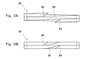
- FIG. 3A is a side view of the spiral ring before being fitted into the annular groove of the main valve body
- FIG. 3B is a side view of the spiral ring after being fitted into the annular groove of the main valve body. It is a side view of a bias cut type flat ring. It is a schematic block diagram of the valve apparatus which concerns on 2nd Embodiment of this invention.
- FIG. 6 is a side view of a flat ring that can be used instead of a spiral ring. It is a sectional view of a part of a conventional valve device.
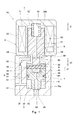
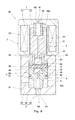
- (First embodiment) 1 and 2 show a valve device 1A according to a first embodiment of the present invention.
- the valve device 1A is used as a pneumatic control device, a gas tank plug, or the like.
- the fluid targeted by the valve device 1A is, for example, high-pressure gas.
- the valve device 1A of the present embodiment is a solenoid valve.
- the valve device 1 ⁇ / b> A includes a housing 2, a main valve body 4 and a pilot valve body 5 disposed in the housing 2, and a solenoid (drive mechanism) 7 that drives the pilot valve body 5.
- a solenoid (drive mechanism) 7 that drives the pilot valve body 5.
- the valve device 1A is not limited to a solenoid valve that employs the solenoid 7 as a drive mechanism.
- a piezoelectric actuator may be used as the drive mechanism.
- the piezoelectric actuator includes a piezoelectric element (for example, a piezo element) and generates a driving force according to an applied voltage.
- a force motor may be used as the drive mechanism. In the force motor, a movable coil is inserted into a cylindrical permanent magnet, and when a current is passed through the movable coil, an exciting force corresponding to the current is generated, and the movable coil is moved by this exciting force. .
- the main valve body 4 and the pilot valve body 5 are both rod-shaped members having a circular cross section, and their central axes are located on the same straight line. In other words, the main valve body 4 and the pilot valve body 5 are arranged coaxially.
- the direction in which the main valve body 4 and the pilot valve body 5 are aligned is the vertical direction (the pilot valve body 5 side is upward, the main valve body is The 4th side is called the lower side.
- the direction in which the main valve body 4 and the pilot valve body 5 are arranged may be a horizontal direction or an oblique direction.
- the housing 2 includes a first body 21 in which a primary passage 31 and a secondary passage 33 constituting the main passage 3 are formed, and a second body 22 in which a solenoid 7 is incorporated.
- the housing 2 has a valve body space 20 between the primary passage 31 and the secondary passage 33.
- the valve body space 20 extends across the first main body 21 and the second main body 22.
- the first main body 21 is formed with a cylindrical first sliding chamber 20a that holds the main valve body 4 so as to be slidable in the vertical direction, and the second main body 22 has a pilot valve body.
- a cylindrical second sliding chamber 20b is formed to hold 5 in a slidable manner in the vertical direction.
- the first main body 21 is provided with a stopper 23 that protrudes radially inward between the first sliding chamber 20a and the second sliding chamber 20b and stops the main valve body 4 that moves upward.
- the valve body space 20 described above is a continuous space defined by the first sliding chamber 20a, the stopper 23, and the second sliding chamber 20b.
- One end (upstream end) of the primary passage 31 is open to the side surface of the first main body 21, and the other end (downstream end) is open to the peripheral surface of the first sliding chamber 20a.
- one end (upstream end) of the secondary passage 33 opens on the bottom surface of the first sliding chamber 20 a, and the other end (downstream end) opens on the lower surface of the first main body 21.
- a first valve seat 25 for the main valve body 4 is formed around the upstream end of the secondary passage 33 on the bottom surface of the first sliding chamber 20a.
- the main valve body 4 is arranged in the housing 2 so as to partition the valve body space 20 into a first pressure chamber 32 and a second pressure chamber 24 communicating with the primary passage 31 and the secondary passage 33.
- the first pressure chamber 32 constitutes the main passage 3 together with the primary passage 31 and the secondary passage 33.
- the main valve body 4 includes a shaft portion 41 having a diameter smaller than the diameter of the peripheral surface of the first sliding chamber 20a and a first sliding chamber 20a extending upward from a peripheral portion on the upper side of the shaft portion 41. And a cylindrical portion 42 having an outer diameter substantially equal to the diameter of the peripheral surface.
- the cylindrical portion 42 is a portion that is slidably held in the first sliding chamber 20a. That is, the first pressure chamber 32 is defined between a portion of the peripheral surface of the first sliding chamber 20 a that is lower than the cylindrical portion 42 and the outer peripheral surface of the shaft portion 41.
- the second pressure chamber 24 is a space facing the upper surface of the shaft portion 41 and the inner peripheral surface of the cylindrical portion 42, a region above the main valve body 4 in the first sliding chamber 20 a, and the stopper 23. It is comprised by the inside and the 2nd sliding chamber 20b.
- a seal member 9 that separates the first pressure chamber 32 and the second pressure chamber 24 is attached to the cylindrical portion 42 of the main valve body 4.
- the outer circumferential surface of the cylindrical portion 42 is provided with an annular groove that opens outward in the radial direction and is covered by the circumferential surface of the first sliding chamber 20a.
- the seal member 9 is disposed in the annular groove. The seal member 9 will be described in detail later.
- the main valve body 4 moves between a closed position where the shaft portion 41 is seated on the first valve seat 25 and an open position where the tubular portion 42 abuts against the stopper 23 to open and close the secondary passage 33.
- the secondary passage 33 is closed and the first pressure chamber 32 is isolated from the secondary passage 33, and when the shaft portion 41 is separated from the first valve seat 25, the secondary passage 33 is closed.
- the passage 33 is opened and the first pressure chamber 32 is connected to the secondary passage 33.
- a first pilot passage 61 is formed in the first main body 21 of the housing 2. One end (upstream end) of the first pilot passage 61 communicates directly with the primary passage 31, and the other end (downstream end) of the first pilot passage 61 communicates with the second pressure chamber 24.
- the first pilot passage 61 is provided with a first throttle 62 in the middle.
- a second pilot passage 63 is formed in the main valve body 4 so as to reach from the second pressure chamber 24 to the secondary passage 33.
- the second pilot passage 63 is disposed on the central axis of the main valve body 4, and one end (upstream end) of the second pilot passage 63 opens on the upper surface of the shaft portion 41, and the other end (downstream end) is the shaft portion. 41 is open to the tip surface.
- the second pilot passage 63 is provided with a second throttle 64 at the end on the second pressure chamber 24 side. The second pilot passage 63 is opened and closed by the pilot valve body 5.
- the pilot valve body 5 is disposed in the second pressure chamber 24.
- a biasing member 55 that presses the pilot valve body 5 against the main valve body 4 is disposed in the second pressure chamber 24.
- the urging member 55 is, for example, a compression coil spring.
- a vertical hole 53 on the central axis and a horizontal hole 54 that intersects with the lower end of the vertical hole 53 are formed in order to avoid the second pressure chamber 24 being vertically divided by the pilot valve body 5.
- a horizontal hole 54 that intersects with the lower end of the vertical hole 53 are formed in order to avoid the second pressure chamber 24 being vertically divided by the pilot valve body 5.
- pilot valve body 5 is inserted into the main body 51 that is slidably held in the second sliding chamber 20 b and the cylindrical portion 42 of the main valve body 4 that protrudes downward from the main body 51. And a shaft portion 52.
- a second valve seat 45 for the pilot valve body 5 is formed around the upstream end of the second pilot passage 63 on the upper surface of the shaft portion 41 of the main valve body 4.
- the second pilot passage 63 is closed, the second pressure chamber 24 is isolated from the second pilot passage 63, and when the shaft portion 52 is separated from the second valve seat 45, The second pilot passage 63 is opened and the second pressure chamber 24 is connected to the second pilot passage 63.
- the inner peripheral surface of the tubular portion 42 of the main valve body 4 and the shaft portion 52 of the pilot valve body 5. Through the gap between the outer peripheral surface of the main valve body 4 and the top surface of the shaft portion 41 of the main valve body 4 and the tip surface of the shaft portion 52 of the pilot valve body 5. Led.
- the solenoid 7 described above drives the pilot valve body 5 in a direction to open the second pilot passage 63 against the urging force of the urging member 55 by energization. That is, the pilot valve body 5 also functions as a movable iron core that is driven by the solenoid 7.
- the solenoid 7 includes a coil 71 wound around the second sliding chamber 20 b and a fixed magnetic pole 72 that is disposed above the pilot valve body 5 and attracts the pilot valve body 5.
- the fixed magnetic pole 72 is also a part of the second main body 22 of the housing 2.
- the shaft portion 52 of the pilot valve body 5 and the cylindrical portion 42 of the main valve body 4 are connected by a pin 8 extending in the horizontal direction perpendicular to the vertical direction.
- the shaft portion 52 of the pilot valve body 5 is formed with a lateral hole 56 that is inserted into the pin 8
- the cylindrical portion 42 of the main valve body 4 is formed with a support hole 43 that supports both ends of the pin 8.
- the support hole 43 is fitted to the pin 8 without a gap, and a gap is provided between the pin 8 and the lateral hole 56 below the pin 8 in a state where the pilot valve body 5 is in contact with the main valve body 4. e1 is formed.
- the horizontal hole 56 may be a circular hole having a diameter larger than that of the pin 8 or may be a long hole extending in the vertical direction with the same width as the diameter of the pin 8.
- the solenoid 7 sets the secondary pressure as the pressure of the secondary passage 33 to P2, the area of the second valve seat 45 to Ap, and the biasing force of the biasing member 55 to Fs.
- the suction force Fc is larger than Fs + Ap (P1-P2).
- the main valve body 4 When the second pilot passage 63 is opened by the pilot valve body 5 and the pressure in the second pressure chamber 24 is lower than the pressure in the first pressure chamber 32, the main valve body 4 has the second pressure passage 32 and the second pressure chamber 32. It is configured to be driven in a direction to open the secondary passage 33 by the differential pressure in the pressure chamber 24.
- the cross-sectional area of the first sliding chamber 20a is A1 and the area of the first valve seat 25 is Am
- the first diaphragm 62 and the second diaphragm 64 and the areas A1 and Am are set so as to satisfy the above.
- the sealing member 9 described above includes a spiral ring 92 that slides on the peripheral surface of the first sliding chamber 20a, and an annular elastic body 91 that urges the spiral ring 92 radially outward.
- the elastic body 91 is, for example, a rubber ring having a substantially square shape or a circular cross section.
- the spiral ring 92 is a single wire wound so that at least both end portions 93 and 94 of the wire overlap the circumferential portion 95 in the axial direction of the spiral ring 92. That is, the spiral ring 92 has a shape in which both end portions 93 and 94 of the wire rod protrude in the axial direction of the spiral ring 92 before being fitted into the annular groove of the cylindrical portion 42 of the main valve body 4, that is, in the natural body. is doing.
- the wire is wound approximately twice, but the wire may be wound approximately 1.5 times or may be wound approximately 3 times.
- the spiral ring 92 is made of a relatively soft material (for example, resin) so that it can be crushed (deformable) in the radial direction or the axial direction.
- a relatively soft material for example, resin
- the sealing performance can be secured by crushing the spiral ring 92 in the radial direction, and by crushing in the axial direction, the main valve body 4 can be secured.
- the cylindrical portion 42 can be deformed into a shape that fits in the annular groove.
- the spiral ring 92 with resin, it is possible to improve the slidability as compared with the rubber ring 92.
- Both end portions 93 and 94 of the wire are tapered so that a wedge-shaped gap is formed between the end portions 95 and 94.
- both end portions 93 and 94 are formed with inclined surfaces that are inclined so as to face each other with the surrounding portion 95 interposed therebetween (in other words, so as to approach the surrounding portion 95 from the tip toward the vicinity thereof).
- the spiral ring 92 is fitted into the annular groove of the cylindrical portion 42 of the main valve body 4, as shown in FIG. 3B, the revolving portion 95 is disposed between the both end portions 93, 94 between the both end portions 93, 94 of the wire. Therefore, the spiral ring 92 can be easily flattened.
- valve device 1A Next, the operation of the valve device 1A will be described. First, as shown in FIG. 1, the main valve body 4 will be described from a state where it is located at the closed position.
- the pilot valve body 5 When the solenoid 7 is not energized, the pilot valve body 5 is pressed against the main valve body 4 by the biasing member 55, and the second pilot passage 63 is closed. That is, the pressure in the second pilot passage 63 is equal to the secondary pressure P2, and the pressure in the first pilot passage 61 and the second pressure chamber 24 is equal to the primary pressure P1. For this reason, the shaft portion 52 of the pilot valve body 5 is caused by the pressing force (Ap (P1-P2)) corresponding to the biasing force Fs of the biasing member 55 and the differential pressure between the second pressure chamber 24 and the second pilot passage 63. It is pressed against the second valve seat 45.
- the shaft portion 41 of the main valve body 4 has a first pressing force (Am (P1-P2)) corresponding to the biasing force Fs of the biasing member 55 and the differential pressure between the second pressure chamber 24 and the secondary passage 33. It is pressed against the valve seat 25.
- the solenoid 7 When the solenoid 7 is energized, first, the pilot valve body 5 is raised by the clearance e1 by the suction force Fc of the solenoid 7. As a result, the second pilot passage 63 is opened, and the fluid flows from the primary passage 31 to the secondary passage 33 through the first pilot passage 61, the second pressure chamber 24 and the second pilot passage 63. As a result, the pressure Pr in the second pressure chamber 24 decreases to a pressure between the primary pressure P1 and the secondary pressure P2, and the main valve body 4 rises due to the differential pressure between the first pressure chamber 32 and the second pressure chamber 24. . As a result, the secondary passage 33 is opened.
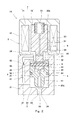
- the main valve body 4 rises until the main valve body 4 comes into contact with the stopper 23. As the main valve body 4 is raised, the pilot valve body 5 connected to the main valve body 4 by the pin 8 is also raised by the suction force Fc of the solenoid 7.
- the distance E from the pilot valve body 5 to the fixed magnetic pole 72 can be separated from the main valve body 4 when the second pilot passage 63 and the secondary passage 33 are closed. Is set larger than the sum of the gap e1 and the distance e2 from the main valve body 4 to the stopper 23 (E> e1 + e2). For this reason, even when the main valve body 4 abuts against the stopper 23, a gap is secured between the pilot valve body 5 and the fixed magnetic pole 72 as shown in FIG. In other words, the main valve body 4 can be pressed against the stopper 23 by the suction force Fc of the solenoid 7.
- the main valve body 4 is restrained to the open position even if the supply of fluid is stopped on the downstream side of the valve device 1A and the fluid no longer flows into the main passage 3. can do.
- the clearance e1 that enables the pilot valve body 5 to be separated from the main valve body 4 is much smaller than the distance e2 that is also the stroke of the main valve body 4.
- the main valve body 4 is driven in the opening direction by the differential pressure between the first pressure chamber 32 and the second pressure chamber 24.
- the pilot passage 63 is opened, the main valve body 4 is opened instantly due to a decrease in the pressure in the second pressure chamber 24. Therefore, the valve device 1A has excellent responsiveness.
- the solenoid 7 for the pilot valve body 5 only needs to have a suction force necessary to drive the pilot valve body 5 by the gap e1 between the pin 8 and the pilot valve body 5, so that the solenoid 7 can be reduced in size.
- the second pilot passage having the second throttle 64 is formed in the main valve body 4, the valve seat area of the pilot valve body 5 is reduced, and the pilot valve body 5 is opened with less driving power. Is possible. Further, since the main valve body 4 and the pilot valve body 5 are connected by the pin 8, the state where the main valve body 4 opens the secondary passage 33 can be maintained by using the suction force of the solenoid 7.
- the sealing member mounted on the main valve body 4 is a flat ring that slides with the peripheral surface of the first sliding chamber 20a, and has an oblique cut so that it can be enlarged when mounted as shown in FIG. It is also possible to use a bias cut type flat ring 96 that is formed and an elastic body that biases the flat ring 96 radially outward.
- a bias cut type flat ring 96 that is formed and an elastic body that biases the flat ring 96 radially outward.
- the seal member 9 including the spiral ring 92 is used as in the present embodiment, the distance at which the surrounding portions 95 of the spiral ring 92 overlap is relatively long. Even if it is not strictly controlled, sufficient sealing performance can be secured. Therefore, it is not necessary to manage the dimensions after mounting like the flat ring 96, and the manufacturing cost can be reduced.
- the distance E from the pilot valve body 5 to the fixed magnetic pole 72 is a clearance e1 that allows the pilot valve body 5 to be separated from the main valve body 4 and a distance e2 from the main valve body 4 to the stopper 23. It was set larger than the sum (E> e1 + e2). However, even if E ⁇ e1 + e2 (including e2 ⁇ E or the case where there is no stopper 23), the pilot valve body 5 comes into contact with the fixed magnetic pole 72 by energizing the solenoid 7, and the pilot valve body 5 and the pin The main valve body 4 connected by 8 can maintain an open position.
- the position of the main valve body 4 may change by a slight gap between the pin 8 and the lateral hole 56.
- E> e1 + e2 the suction force Fc of the solenoid 7 can be applied to the main valve body 4 located at the open position. Thereby, the position fluctuation
- This modification can also be applied to second to fourth embodiments described later.
- the seal member 9 does not necessarily include the elastic body 91 that urges the spiral ring 92 outward in the radial direction.
- the elastic body 91 can be omitted. This modification is also applicable to the second to fourth embodiments described later.
- valve device 1B Referring to a second embodiment of the present invention
- the same components as those in the first embodiment are denoted by the same reference numerals, and redundant description is omitted.
- the lateral hole 56 provided in the pilot valve body 5 is fitted to the pin 8 without a gap, and the pilot valve body 5 is interposed between the support hole 43 provided in the main valve body 4 and the pin 8.
- a gap e1 that allows separation from the main valve body 4 is formed.
- a valve device 1C according to a third embodiment of the present invention will be described.
- a first pilot passage 61 having a first throttle 62 is formed in the main valve body 4, and the upstream end of the first pilot passage 61 communicates with the primary passage 31 indirectly through the first pressure chamber 32. is doing.
- a plurality of first pilot passages 61 may be formed around the shaft portion 41 of the main valve body 4.
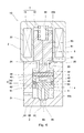
- a valve device 1D according to a fourth embodiment of the present invention will be described with reference to FIG.
- a first pilot passage 61 having a first aperture 62 is formed in the fixed magnetic pole 72.
- This embodiment assumes that almost the entire valve device 1D is inserted into a gas tank (not shown). That is, the upstream end of the first pilot passage 61 indirectly communicates with the primary passage 31 through the internal space of the gas tank.
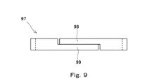
- a flat ring 97 that slides with the peripheral surface of the first sliding chamber 20a as shown in FIG. 9 may be used instead of the spiral ring 92.
- the flat ring 97 has a stepped shape so that both ends 98 and 99 of the wire extending in the circumferential direction of the flat ring 97 are in surface contact with each other on a plane perpendicular to the axial direction of the flat ring 97. is there.
- both end portions 98 and 99 of the wire are cut out from the other side so as to engage with each other.
- both end portions 98 and 99 of the wire may extend in the circumferential direction of the flat ring 97 at half the height of the intermediate portion of the wire. In this configuration as well, the same effect as when the spiral ring 92 is used can be obtained.
- the flat ring 97 may be urged radially outward by the elastic body 91, or the elastic body 91 may be omitted.
- the present invention is widely applicable to valve devices for various uses.
- Valve device 2 Housing 20 Valve body space 23 Stopper 24 Second pressure chamber 3 Main passage 31 Primary passage 32 First pressure chamber 33 Secondary passage 4 Main valve body 5 Pilot valve body 55 Energizing member 61 First pilot passage 62 First throttle 63 Second pilot passage 64 Second throttle 7 Solenoid 8 Pin 9 Seal member 91 Elastic body 92 Spiral ring 93, 94 End portion 95 Circumferential portion 97 Flat ring 98, 99 End portion e1 Crevice
Landscapes
- Engineering & Computer Science (AREA)
- General Engineering & Computer Science (AREA)
- Mechanical Engineering (AREA)
- Chemical & Material Sciences (AREA)
- Analytical Chemistry (AREA)
- Chemical Kinetics & Catalysis (AREA)
- General Chemical & Material Sciences (AREA)
- Oil, Petroleum & Natural Gas (AREA)
- Combustion & Propulsion (AREA)
- Magnetically Actuated Valves (AREA)
- Fluid-Driven Valves (AREA)
Priority Applications (1)
| Application Number | Priority Date | Filing Date | Title |
|---|---|---|---|
| US15/551,297 US10161360B2 (en) | 2015-02-26 | 2016-02-23 | Valve device |
Applications Claiming Priority (2)
| Application Number | Priority Date | Filing Date | Title |
|---|---|---|---|
| JP2015036636A JP6463647B2 (ja) | 2015-02-26 | 2015-02-26 | 弁装置 |
| JP2015-036636 | 2015-02-26 |
Publications (1)
| Publication Number | Publication Date |
|---|---|
| WO2016136239A1 true WO2016136239A1 (ja) | 2016-09-01 |
Family
ID=56788326
Family Applications (1)
| Application Number | Title | Priority Date | Filing Date |
|---|---|---|---|
| PCT/JP2016/000955 Ceased WO2016136239A1 (ja) | 2015-02-26 | 2016-02-23 | 弁装置 |
Country Status (3)
| Country | Link |
|---|---|
| US (1) | US10161360B2 (enExample) |
| JP (1) | JP6463647B2 (enExample) |
| WO (1) | WO2016136239A1 (enExample) |
Cited By (3)
| Publication number | Priority date | Publication date | Assignee | Title |
|---|---|---|---|---|
| WO2019001249A1 (zh) * | 2017-06-30 | 2019-01-03 | 浙江三花汽车零部件有限公司 | 一种电动阀 |
| JP2021017948A (ja) * | 2019-07-22 | 2021-02-15 | 日本電産トーソク株式会社 | 電磁弁、および流路装置 |
| JP2021110442A (ja) * | 2020-01-15 | 2021-08-02 | 日立Astemo株式会社 | バルブ機構および圧力緩衝装置 |
Families Citing this family (28)
| Publication number | Priority date | Publication date | Assignee | Title |
|---|---|---|---|---|
| DE102015005977A1 (de) * | 2015-05-08 | 2016-11-10 | Daimler Ag | Entnahmeventil |
| KR101821597B1 (ko) * | 2016-05-10 | 2018-01-26 | 영도산업 주식회사 | 유체 제어용 솔레노이드 밸브 |
| KR102274114B1 (ko) * | 2017-01-25 | 2021-07-06 | 현대자동차주식회사 | 독립 거동 가능한 파일럿 플런저 헤드를 포함하는 솔레노이드 밸브 |
| DE102018113748B3 (de) * | 2018-06-08 | 2019-07-11 | Leinemann Gmbh & Co. Kg | Tankventil und Tank mit einem derartigen Ventil |
| JP2020070900A (ja) * | 2018-11-01 | 2020-05-07 | 株式会社ニッキ | パイロット式電磁弁 |
| US11499726B2 (en) * | 2019-09-17 | 2022-11-15 | Emerson Electric Co. | Coaxial gas valve assemblies including electronically controlled solenoids |
| CN211901785U (zh) * | 2019-12-24 | 2020-11-10 | 博西华电器(江苏)有限公司 | 电磁阀及燃气灶 |
| DE102020203700A1 (de) * | 2020-03-23 | 2021-09-23 | Robert Bosch Gesellschaft mit beschränkter Haftung | Ventilvorrichtung für ein Brennstoffzellensystem und Tankvorrichtung zur Speicherung eines gasförmigen Mediums |
| DE102020206678A1 (de) * | 2020-05-28 | 2021-12-02 | Robert Bosch Gesellschaft mit beschränkter Haftung | Absperrventil für einen Druckgasbehälter, Druckgasbehälter |
| DE102020211860A1 (de) * | 2020-09-23 | 2022-03-24 | Robert Bosch Gesellschaft mit beschränkter Haftung | Tankvorrichtung mit einer Ventilvorrichtung |
| DE102020211865A1 (de) | 2020-09-23 | 2022-03-24 | Robert Bosch Gesellschaft mit beschränkter Haftung | Tankvorrichtung zur Speicherung eines gasförmigen Mediums mit einer Ventilvorrichtung |
| DE102020211862A1 (de) | 2020-09-23 | 2022-03-24 | Robert Bosch Gesellschaft mit beschränkter Haftung | Tankvorrichtung zur Speicherung eines gasförmigen Mediums mit einer Ventilvorrichtung |
| DE102021205810A1 (de) * | 2021-06-09 | 2022-12-15 | Robert Bosch Gesellschaft mit beschränkter Haftung | Brennstoffzellensystem, Gastankvorrichtung und Absperrventil für eine Gastankvorrichtung |
| DE102021207320A1 (de) * | 2021-07-12 | 2023-01-12 | Robert Bosch Gesellschaft mit beschränkter Haftung | Sperrventil und Steuerungsverfahren zum Steuern eines Wasserstoffflusses aus einem Drucktank |
| DE102021209468A1 (de) * | 2021-08-30 | 2023-03-02 | Robert Bosch Gesellschaft mit beschränkter Haftung | Magnetventil sowie Wasserstofftanksystem mit Magnetventil |
| DE102021211815A1 (de) * | 2021-10-20 | 2023-04-20 | Robert Bosch Gesellschaft mit beschränkter Haftung | Brennstoffzellensystem, Gastankvorrichtung und Absperreinrichtung für eine Gastankvorrichtung |
| DE102021212129A1 (de) * | 2021-10-27 | 2023-04-27 | Robert Bosch Gesellschaft mit beschränkter Haftung | Absperrventil sowie Wasserstofftanksystem mit Absperrventil |
| DE102022200799A1 (de) * | 2022-01-25 | 2023-07-27 | Robert Bosch Gesellschaft mit beschränkter Haftung | Absperrventil sowie Wasserstofftanksystem mit Absperrventil |
| DE102022201837A1 (de) * | 2022-02-22 | 2023-08-24 | Robert Bosch Gesellschaft mit beschränkter Haftung | Absperrventil für Brenngastanksysteme sowie Brenngastanksystem mit Absperrventil |
| DE102022201983A1 (de) * | 2022-02-25 | 2023-08-31 | Robert Bosch Gesellschaft mit beschränkter Haftung | Absperrventil sowie Wasserstofftanksystem mit Absperrventil |
| DE102022201957A1 (de) * | 2022-02-25 | 2023-08-31 | Robert Bosch Gesellschaft mit beschränkter Haftung | Ventilvorrichtung mit verkippbarem Führungselement sowie Fluidsystem |
| DE102022202170A1 (de) * | 2022-03-03 | 2023-09-07 | Robert Bosch Gesellschaft mit beschränkter Haftung | Absperrventil sowie Wasserstofftanksystem mit Absperrventil |
| WO2023179797A1 (zh) * | 2022-03-25 | 2023-09-28 | 浙江盾安人工环境股份有限公司 | 电磁截止阀 |
| EP4270142B1 (de) * | 2022-04-28 | 2024-11-20 | Robert Bosch GmbH | Druckminderungsventil, wasserstofftank und kraftfahrzeug |
| WO2023233469A1 (ja) * | 2022-05-30 | 2023-12-07 | 株式会社ジェイテクト | 弁アセンブリ |
| DE102023202600A1 (de) * | 2023-03-22 | 2024-09-26 | Robert Bosch Gesellschaft mit beschränkter Haftung | Absperrventil sowie Wasserstofftanksystem mit Absperrventil |
| DE102024202948A1 (de) * | 2024-03-28 | 2025-10-02 | Robert Bosch Gesellschaft mit beschränkter Haftung | Sicherheitsmagnetventileinrichtung und Verfahren zum Betreiben einer Sicherheitsmagnetventileinrichtung |
| JP2025155376A (ja) * | 2024-04-01 | 2025-10-14 | トヨタ自動車株式会社 | 電磁弁の制御装置 |
Citations (5)
| Publication number | Priority date | Publication date | Assignee | Title |
|---|---|---|---|---|
| JPS6185775U (enExample) * | 1984-11-12 | 1986-06-05 | ||
| JPS6358312B2 (enExample) * | 1981-08-31 | 1988-11-15 | Tokyo Taiyoo Kk | |
| JP2002071044A (ja) * | 2000-09-01 | 2002-03-08 | Aisan Ind Co Ltd | 双方向型パイロット式電磁流路開閉弁と双方向型配管 |
| WO2011158457A1 (ja) * | 2010-06-15 | 2011-12-22 | 川崎重工業株式会社 | 電磁式開閉弁 |
| WO2015033528A1 (ja) * | 2013-09-03 | 2015-03-12 | 川崎重工業株式会社 | 弁装置 |
Family Cites Families (11)
| Publication number | Priority date | Publication date | Assignee | Title |
|---|---|---|---|---|
| US2575272A (en) * | 1947-07-17 | 1951-11-13 | Skinner Chuck Company | Rapid closure valve for high-flow rates at low-pressure drop |
| US4699351A (en) * | 1984-07-11 | 1987-10-13 | Target Rock Corporation | Pressure responsive, pilot actuated, modulating valve |
| US4938450A (en) * | 1989-05-31 | 1990-07-03 | Target Rock Corporation | Programmable pressure reducing apparatus for throttling fluids under high pressure |
| US5048790A (en) * | 1990-07-18 | 1991-09-17 | Target Rock Corporation | Self-modulating control valve for high-pressure fluid flow |
| US5271599A (en) * | 1990-09-28 | 1993-12-21 | Kolchinsky Abel E | Modular solenoid valve |
| JP2832777B2 (ja) * | 1992-08-03 | 1998-12-09 | 昭一 岩本 | 一方向弁装置 |
| JPH0875029A (ja) | 1994-09-07 | 1996-03-19 | Nichiden Kogyo Kk | 電磁弁 |
| WO2003036148A1 (en) * | 2001-10-18 | 2003-05-01 | Katakura Industries Co., Ltd. | Cutoff valve and fuel feed mechanism |
| JP4330943B2 (ja) * | 2003-06-30 | 2009-09-16 | 株式会社ジェイテクト | 水素ガス用高圧バルブ及び水素ガス用減圧装置 |
| JP4685903B2 (ja) * | 2008-06-11 | 2011-05-18 | 株式会社酉島製作所 | 流体機械のシール装置 |
| JP4805320B2 (ja) * | 2008-09-11 | 2011-11-02 | 川崎重工業株式会社 | 電磁開閉弁 |
-
2015
- 2015-02-26 JP JP2015036636A patent/JP6463647B2/ja not_active Expired - Fee Related
-
2016
- 2016-02-23 WO PCT/JP2016/000955 patent/WO2016136239A1/ja not_active Ceased
- 2016-02-23 US US15/551,297 patent/US10161360B2/en active Active
Patent Citations (5)
| Publication number | Priority date | Publication date | Assignee | Title |
|---|---|---|---|---|
| JPS6358312B2 (enExample) * | 1981-08-31 | 1988-11-15 | Tokyo Taiyoo Kk | |
| JPS6185775U (enExample) * | 1984-11-12 | 1986-06-05 | ||
| JP2002071044A (ja) * | 2000-09-01 | 2002-03-08 | Aisan Ind Co Ltd | 双方向型パイロット式電磁流路開閉弁と双方向型配管 |
| WO2011158457A1 (ja) * | 2010-06-15 | 2011-12-22 | 川崎重工業株式会社 | 電磁式開閉弁 |
| WO2015033528A1 (ja) * | 2013-09-03 | 2015-03-12 | 川崎重工業株式会社 | 弁装置 |
Cited By (6)
| Publication number | Priority date | Publication date | Assignee | Title |
|---|---|---|---|---|
| WO2019001249A1 (zh) * | 2017-06-30 | 2019-01-03 | 浙江三花汽车零部件有限公司 | 一种电动阀 |
| US11156296B2 (en) | 2017-06-30 | 2021-10-26 | Zhejiang Sanhua Automotive Components Co., Ltd. | Flow control valve |
| JP2021017948A (ja) * | 2019-07-22 | 2021-02-15 | 日本電産トーソク株式会社 | 電磁弁、および流路装置 |
| JP7293941B2 (ja) | 2019-07-22 | 2023-06-20 | ニデックパワートレインシステムズ株式会社 | 電磁弁、および流路装置 |
| JP2021110442A (ja) * | 2020-01-15 | 2021-08-02 | 日立Astemo株式会社 | バルブ機構および圧力緩衝装置 |
| JP7297693B2 (ja) | 2020-01-15 | 2023-06-26 | 日立Astemo株式会社 | バルブ機構および圧力緩衝装置 |
Also Published As
| Publication number | Publication date |
|---|---|
| US10161360B2 (en) | 2018-12-25 |
| US20180038507A1 (en) | 2018-02-08 |
| JP6463647B2 (ja) | 2019-02-06 |
| JP2016156485A (ja) | 2016-09-01 |
Similar Documents
| Publication | Publication Date | Title |
|---|---|---|
| JP6463647B2 (ja) | 弁装置 | |
| WO2015033528A1 (ja) | 弁装置 | |
| KR102518258B1 (ko) | 가스용 솔레노이드 밸브 | |
| JP5873451B2 (ja) | 弁装置 | |
| JP5952760B2 (ja) | 減衰弁 | |
| JP4805320B2 (ja) | 電磁開閉弁 | |
| JP5952762B2 (ja) | 減衰弁 | |
| CN102203479B (zh) | 阀门组件 | |
| US20060021664A1 (en) | Three-port electromagnetic valve | |
| WO2014174759A1 (ja) | 過流防止機能付き弁装置 | |
| CN105874253B (zh) | 电磁阀 | |
| EP3919795B1 (en) | Electromagnetic gas valve | |
| US9856992B2 (en) | Solenoid valve | |
| WO2015125404A1 (ja) | 弁装置 | |
| JP5675777B2 (ja) | 流体作動機器用の面シーリング環状バルブ | |
| JP6322562B2 (ja) | 電動弁 | |
| JP5722164B2 (ja) | 減圧装置 | |
| CN103688091B (zh) | 阀模块 | |
| JP5403772B2 (ja) | 減衰弁 | |
| CN107131165A (zh) | 电磁阀和压力流体控制设备 | |
| JP5712092B2 (ja) | パイロット機能付き弁 | |
| JP5955763B2 (ja) | 弁構造 | |
| JP5537697B2 (ja) | 減衰弁 |
Legal Events
| Date | Code | Title | Description |
|---|---|---|---|
| 121 | Ep: the epo has been informed by wipo that ep was designated in this application |
Ref document number: 16754990 Country of ref document: EP Kind code of ref document: A1 |
|
| WWE | Wipo information: entry into national phase |
Ref document number: 15551297 Country of ref document: US |
|
| NENP | Non-entry into the national phase |
Ref country code: DE |
|
| 122 | Ep: pct application non-entry in european phase |
Ref document number: 16754990 Country of ref document: EP Kind code of ref document: A1 |