WO2016133018A1 - ワイヤーハーネス - Google Patents
ワイヤーハーネス Download PDFInfo
- Publication number
- WO2016133018A1 WO2016133018A1 PCT/JP2016/054129 JP2016054129W WO2016133018A1 WO 2016133018 A1 WO2016133018 A1 WO 2016133018A1 JP 2016054129 W JP2016054129 W JP 2016054129W WO 2016133018 A1 WO2016133018 A1 WO 2016133018A1
- Authority
- WO
- WIPO (PCT)
- Prior art keywords
- peripheral surface
- liner sheet
- wire harness
- exterior material
- portions
- Prior art date
- Legal status (The legal status is an assumption and is not a legal conclusion. Google has not performed a legal analysis and makes no representation as to the accuracy of the status listed.)
- Ceased
Links
Images



Classifications
-
- B—PERFORMING OPERATIONS; TRANSPORTING
- B60—VEHICLES IN GENERAL
- B60R—VEHICLES, VEHICLE FITTINGS, OR VEHICLE PARTS, NOT OTHERWISE PROVIDED FOR
- B60R16/00—Electric or fluid circuits specially adapted for vehicles and not otherwise provided for; Arrangement of elements of electric or fluid circuits specially adapted for vehicles and not otherwise provided for
- B60R16/02—Electric or fluid circuits specially adapted for vehicles and not otherwise provided for; Arrangement of elements of electric or fluid circuits specially adapted for vehicles and not otherwise provided for electric constitutive elements
-
- H—ELECTRICITY
- H01—ELECTRIC ELEMENTS
- H01B—CABLES; CONDUCTORS; INSULATORS; SELECTION OF MATERIALS FOR THEIR CONDUCTIVE, INSULATING OR DIELECTRIC PROPERTIES
- H01B7/00—Insulated conductors or cables characterised by their form
-
- H—ELECTRICITY
- H02—GENERATION; CONVERSION OR DISTRIBUTION OF ELECTRIC POWER
- H02G—INSTALLATION OF ELECTRIC CABLES OR LINES, OR OF COMBINED OPTICAL AND ELECTRIC CABLES OR LINES
- H02G3/00—Installations of electric cables or lines or protective tubing therefor in or on buildings, equivalent structures or vehicles
- H02G3/22—Installations of cables or lines through walls, floors or ceilings, e.g. into buildings
Definitions
- the present invention relates to a wire harness, and particularly to a wire harness provided with an exterior material mounted on a vehicle or the like.
- a wire harness mounted on a vehicle such as an automobile is equipped with a corrugated tube capable of protecting an electric wire group or an exterior material such as a protector capable of protecting the electric wire group and restricting a routing route.
- the exterior material is required to be lightweight and rigid enough to accurately regulate the path of the wire harness, and may be required to bend or extend or contract depending on the routing path.
- a non-woven fabric As a wire harness equipped with a conventional exterior material, for example, a non-woven fabric is formed into a three-dimensional shape by hot pressing, and the non-woven fabric's basis weight (weight per unit volume) is made different, or unevenness in the radial direction is partially formed By doing so, what forms the path
- a non-woven fabric is formed into a flat bellows shape by hot pressing to constitute an exterior material having improved stretchability and bendability (for example, see Patent Document 2).
- the conventional wire harness as described above has a problem that the manufacturing cost of the exterior material is high, and the manufacturing cost of the wire harness using the exterior material is high.
- the nonwoven fabric absorbs water, it is difficult for the water to be drained, so that there is a problem that the exterior material cannot be disposed in the wet area.
- the present invention can easily achieve both a path regulation function and an expansion / contraction / bending allowance function, and is provided with a lightweight and low-cost exterior material that is excellent in drainage even if it is placed in a wet area.
- the purpose is to provide a harness.
- the wire harness according to the present invention is a wire harness including an exterior material that is sheathed in a specific section so as to surround the specific section in the length direction of the electric wire group, and the exterior material is a predetermined one.
- a plastic corrugated cardboard material having a pair of liner sheet portions facing each other in parallel with a gap layer therebetween, and a plurality of rib-like connection portions that divide the gap layer into a plurality while integrally joining both liner sheet portions
- a part of the sheet portion is partially cut into a slit shape between the adjacent connecting portions, and at least one of the outer peripheral surface and the inner peripheral surface of the cylindrical body has a partially corrugated longitudinal sectional shape. It is those who are.
- the liner sheet portion is formed such that at least one of the outer peripheral surface and the inner peripheral surface of the partial region in the axial direction of the exterior material partially has a corrugated longitudinal sectional shape. The part is cut off, and it becomes low bending rigidity.
- the pair of liner sheet portions of the exterior material are continuous in the axial direction and are connected to each other by a rib-like connecting portion, so that high bending rigidity is achieved. Accordingly, it is possible to provide a path regulating function to the remaining axial portion while providing a function of allowing expansion / contraction and bending to a partial region of the exterior material in the axial direction.
- a plastic corrugated cardboard material since a plastic corrugated cardboard material is used, it does not absorb water, and even if it is placed in the water-receiving area, it has excellent drainage properties, and it becomes a low-cost exterior material.
- the rib-like connecting portions are respectively cut at a plurality of locations in the circumferential direction corresponding to the corners of the polygonal cylindrical shape, while the axial portions in the partial region are
- the liner sheet portion on the inner peripheral surface side or the outer peripheral surface side may be continuous in the circumferential direction.
- a polygonal cylindrical body can be easily formed from a plate-like plastic corrugated cardboard material, and its outer peripheral surface and / or inner peripheral surface can be easily formed in a partial region in the axial direction of the exterior material. Can be processed into a corrugated longitudinal section.
- a part of the liner sheet portion on the outer peripheral surface side and a part of the liner sheet portion on the inner peripheral surface side in a partial region in the axial direction of the exterior material may be excised.
- a partial region in the axial direction of the exterior material has a shape similar to a bellows, and good flexibility and stretchability can be obtained.
- a wire having a lightweight and low-cost exterior material that can easily achieve both a path regulation function and an expansion / contraction / bending permission function, and has excellent drainage performance even when placed in a water-filled area.
- a harness can be provided.
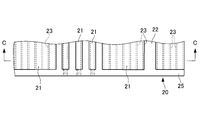
- FIG. 2A is the principal part top view of the raw material.
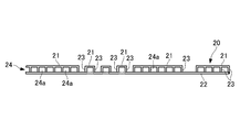
- FIG. 2B is a principal part front view of the raw material.
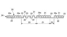
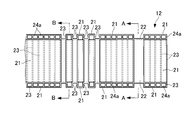
- FIG. 2C is CC sectional view taken on the line of FIG. 2A. It is a principal part top view of the exterior material in the wire harness which concerns on one embodiment of this invention.
- FIG. 4 is a cross-sectional view taken along line AA in FIG. 3.
- FIG. 4 is a cross-sectional view taken along line BB in FIG. 3. It is a cross-sectional end view in the path
- (One embodiment) 1 to 5 show a wire harness according to an embodiment of the present invention.
- the wire harness of the present embodiment is routed, for example, near a bent portion of a car body panel of an automobile or between a car body panel and a movable part in which electrical components are incorporated.
- the wire harness 10 of this embodiment includes a bundle of electric wires 11 composed of a plurality of electric wires, and an electric wire group in a specific exterior section in the length direction along the routing route of the electric wires 11. 11 and an exterior material 12 that is exteriorized so as to surround 11.
- the electric wire group 11 is used for, for example, an electric actuator or sensor mounted on a vehicle or other equipment, and includes any one of a power supply line, a signal line, a ground line, and the like. It is comprised by the some electric wire.
- Each electric wire of the electric wire group 11 includes, for example, a stranded wire conductor having good conductivity and an electrically insulating coating resin that concentrically surrounds the conductor.
- the exterior material 12 includes a pair of liner sheet portions 21 and 22 and a plurality of rib-like shapes that connect the liner sheet portions 21 and 22 in parallel with a predetermined gap therebetween.
- a plate-like plastic corrugated cardboard material 20 having a connecting portion 23.
- the plastic corrugated cardboard material 20 is formed of a plate-like body similar to corrugated paper having a flute and a liner sheet, and is also called corrugated plastic.
- the pair of liner sheet portions 21 and 22 are plastic sheets facing in parallel across a certain gap layer 24, for example, a sheet made of polypropylene resin (PP) having a low specific gravity and excellent heat resistance and mechanical strength. They have the same thickness and material.
- PP polypropylene resin
- the plurality of rib-like connecting portions 23 are a plurality of substantially parallel wall portions that divide the gap layer 24 into a plurality of strip-like spaces 24a while integrally connecting the liner sheet portions 21 and 22, and each liner sheet portion. 21 and 22 are substantially the same thickness and the same material. That is, the plurality of connecting portions 23 are also made of plastic, for example, polypropylene resin (PP).
- PP polypropylene resin
- This plastic corrugated cardboard material 20 is uniformly extruded so as to have a ladder-like cross-sectional shape such as a path regulation region Z1 shown in cross section in FIG. 2C, and then cut into a predetermined material contour shape. Further, secondary processing is performed in which partial cutting or excision is performed in the thickness direction.
- the plurality of rib-like connecting portions 23 extend in parallel with each other. As shown in FIGS. 2B and 2C, not only the extending direction of these connecting portions 23 but also the cross-sections of the plurality of connecting portions 23 They are completely parallel.
- each pair of adjacent connecting portions 23 may be inclined in opposite directions, and the cross sections of the plurality of connecting portions 23 may alternately reverse the inclination directions.
- each pair of adjacent connecting portions 23 inclines in a substantially “C” shape so that the cross section of each of the pair of connecting portions 23 approaches on either side of the liner sheet portions 21 and 22 and separates on the other side.
- the plurality of connecting portions 23 may be configured so as to have a corrugated cross-sectional shape close to the flute of the cardboard as a whole.
- the exterior material 12 is a cylindrical body obtained by bending a plastic corrugated cardboard material 20 into a polygonal cylindrical shape with a plurality of rib-like connecting portions 23 extending in the circumferential direction.
- the polygonal cross-sectional shape forming the internal space 12c for example, a quadrangular (rectangular or square) cross-sectional shape.
- the liner sheet 21 on the outer peripheral side and / or the liner on the inner peripheral side is partially cut out in a slit shape between the adjacent rib-shaped connecting portions 23. Then, at least one of the outer peripheral surface 12a and the inner peripheral surface 12b of the exterior material 12 partially has a rectangular wave-shaped (corrugated) longitudinal cross-sectional shape.
- the parallel rib-shaped connecting portion 23 extends in the circumferential direction corresponding to the polygonal cylindrical corner of the exterior material 12 over substantially the entire axial direction of the exterior material 12. Are cut at a plurality of locations.
- At least one of the outer peripheral surface 12a and the inner peripheral surface 12b is partially corrugated in longitudinal cross-sectional shape.
- the other (the other one) of the outer peripheral surface 12a and the inner peripheral surface 12b in the expansion / contraction and bending permissible region Z2 of the exterior material 12 partially has a corrugated longitudinal cross-sectional shape
- the other (the other one) In this case, the outer peripheral surface 12a and the inner peripheral surface 12b partially have a corrugated longitudinal sectional shape in the entire expansion / contraction and bending allowable region Z2. explain.
- both the outer peripheral surface 12a and the inner peripheral surface 12b partially have a corrugated longitudinal sectional shape, and the outer peripheral surface The portion where the liner sheet portion 21 on the 12a side is cut out in a slit shape and the portion where the liner sheet portion 21 on the outer peripheral surface 12a side is left in the shape of a band supported by a pair of connecting portions 23 alternately Is arranged.
- the liner sheet portion 22 on the inner peripheral surface 12b side is surrounded by an axial section in which the liner sheet portion 21 on the outer peripheral surface 12a side is cut into a slit extending in the circumferential direction.
- a pair of connecting portions 23 that are formed continuously in the direction and are adjacent to each other at both end portions thereof are arranged so as to be integrally coupled.
- the exterior material 12 further includes a thin wall region Z3 having a relatively low bending rigidity adjacent to the path regulation region Z1 or the expansion / contraction and bending allowable region Z2.
- the liner sheet portion 21 on the outer peripheral surface 12a side or the liner sheet portion 22 on the inner peripheral surface 12b side, and the connecting portion 23 are cut off, and the outer peripheral surface 12a side or inner peripheral surface is cut.
- the thin region Z3 is configured by only one of the liner sheet portions 21 and 22 on the surface 12b side, for example, only the liner sheet portion 22 on the inner peripheral surface 12b side.
- slit-shaped excision is performed by excising the liner sheet portion 21 on the outer peripheral surface 12a side or the liner sheet portion 22 on the inner peripheral surface 12b side located between a pair of adjacent rib-shaped connecting portions 23.
- slit sheet width is narrow and the liner sheet portion 21 on the outer peripheral surface 12a side or the liner sheet portion 22 on the inner peripheral surface 12b side remains between a pair of adjacent rib-shaped connecting portions 23, It is good that they do not interfere with each other.
- the plastic corrugated board material 20 is provided with an adhesive margin portion 25 for connecting both ends bent into a cylindrical shape during the secondary processing.
- the cut portion may be formed to extend to the bonding margin portion 25 at the time of the above-described slit-shaped cut.
- the corrugated longitudinal section of the outer peripheral surface 12a and / or the inner peripheral surface 12b is formed from a plate-like plastic corrugated cardboard material 20 in a partial region in the axial direction.
- the polygonal cylindrical outer packaging material 12 can be easily produced.
- one of the liner sheet portions 21 and 22 is formed such that at least one of the outer peripheral surface 12a and the inner peripheral surface 12b partially has a corrugated longitudinal sectional shape. Since the part is cut off, it has low bending rigidity.
- the pair of liner sheet portions 21 and 22 of the exterior material 12 are connected to each other by a plurality of rib-like connecting portions 23 that are continuous in parallel with each other in the axial direction. Therefore, it has high bending rigidity.
- exterior_material 12 has comprised the rectangular cylinder shape which continues in an axial direction and the circumferential direction
- region Z3 is from the expansion-contraction and bending
- the length of the path regulation region Z1, the length of the expansion / contraction and bending allowable region Z2 and the length of the thin region Z3 in the axial direction of the exterior material 12 can be appropriately set according to the range of the secondary processing. Therefore, in a partial section in the axial direction of the exterior member 12 where expansion and contraction is required, the expansion and contraction and bending allowance area Z2 is allowed to exhibit the expansion and contraction and bending allowable functions, and the path regulation of the wire group 11 is required. In this section, the required route restriction function can be exhibited by the route restriction region Z1.
- the outer diameter or the inner diameter is partially changed by the thin-walled area Z3, slight bending or bending is absorbed in the middle of the path regulation section, or between the path regulation area Z1 and the expansion / contraction and bending allowance area Z2.
- An appropriate rigidity adjustment section can be set.
- the outer packaging material 12 uses a plastic corrugated cardboard material, it does not absorb water and has excellent drainage even if it is disposed in a wet area. Furthermore, since the plastic corrugated cardboard material 20 can be produced from general plastic corrugated cardboard frequently used for returnable boxes, floor-curing sheets, etc., the packaging material 12 can be manufactured at low cost.
- the present embodiment it is only necessary to perform the secondary process of cutting a part of the liner sheet portions 21 and 22 into a slit shape on at least one side of the outer peripheral surface 12a and the inner peripheral surface 12b of the exterior material 12.
- the expansion / contraction and bending allowance area Z2 can be formed in a part of the axial direction, and the path restriction area Z1 can be formed in another section. Therefore, the path regulation function required in the exterior section of the exterior material 12 can be easily made compatible with the function of allowing expansion and contraction and bending.
- the packaging material 12 is formed using the plastic corrugated cardboard material 20, the wire harness 10 provided with the lightweight and low-cost packaging material 12 having excellent drainage even when arranged in the water-receiving area can be provided.
- FIG. 6 shows a wire harness according to another embodiment of the present invention.
- the present embodiment is different from the first embodiment in that an exterior material 32 is provided in place of the exterior material 12 in the first embodiment described above, but other configurations are the same as those in the first embodiment described above.
- the same or similar components will be described using the reference numerals of the corresponding components in the first embodiment.
- the exterior material 32 that is sheathed on the electric wire 11 of the wire harness 10 leaves the liner sheet 21 on one side of the plastic corrugated cardboard material 20 on the outer peripheral surface 32a side, After forming a substantially V-shaped groove from the other surface side to be the inner peripheral surface 32b, the plastic corrugated cardboard material 20 is bent into a cylindrical shape and joined at an adhesive margin portion (not shown) on the outer peripheral surface 32a side, An internal space 32c into which the wire group 11 can be inserted is formed.
- a part of the exterior material 32 in the axial direction is an expansion / contraction and bending allowable region Z2, and both the outer peripheral surface 32a and the inner peripheral surface 32b are partially within the expansion / contraction and bending allowable region Z2 of the external material 32.
- seat part 21 by the side of the outer peripheral surface 32a of the exterior material 32 was cut off in the shape of a slit, and the liner sheet
- the liner sheet portion 22 on the inner peripheral surface 12b side is cut at a plurality of locations corresponding to the corners of the polygonal cylinder, while the liner sheet portion 21 on the outer peripheral surface 32a side is cut into a slit extending in the circumferential direction.
- it is continuously formed between the connecting portions 23 on both sides thereof, and in the section corresponding to the portion where the liner sheet portion 21 on the outer peripheral surface 32a side is left in a strip shape, it is cut into a slit shape. .
- each surface corresponding to each side of the polygonal cross-section of the exterior member 32 has a rectangular wave-like vertical cross-sectional shape. Therefore, the exterior member 32 has a shape similar to a bellows, and good flexibility and stretchability are obtained.
- the expansion / contraction and bending allowance area Z2 can be formed in part, and the path restriction area Z1 can be formed in other sections. Therefore, the path regulation function required in the exterior section of the exterior material 12 can be easily made compatible with the function of allowing expansion and contraction and bending.
- the exterior material 12 is formed using the plastic corrugated cardboard material 20, the wire harness 10 provided with the lightweight and low-cost exterior material 12 excellent in drainage even if it is disposed in the wet area. can do.
- the exterior materials 12 and 32 have a quadrangular cross-sectional shape, but may be a triangle or a polygonal cylinder of a quadrangle or more, and a regular polygon. It does not have to have a cross section.
- outer peripheral surface 12a and the inner peripheral surface 12b have a corrugated longitudinal cross-sectional shape over the entire expansion / contraction / bending allowable region Z2 has been described.
- the outer peripheral surface 12a and the inner peripheral surface 12b may have a corrugated longitudinal sectional shape.
- the blade when the slit-shaped cut portion is formed in the plastic corrugated cardboard material 20, the blade can be moved along the rib-shaped connecting portion 23 and mechanically easily cut. Alternatively, it may be melted by heat.
- the exterior materials 12 and 32 are made from one plastic corrugated cardboard material 20, but, for example, the same configuration as the exterior material 12 having an inner diameter corresponding to the outer diameter of the exterior material 12 You may further pile up the exterior material of a different size which has.
- the present invention can easily achieve both a path regulation function and an expansion / contraction / bending allowance function, and is excellent in drainage even when placed in a wet area.
- the wire harness provided with the exterior material can be provided, and is useful for all wire harnesses provided with the exterior material mounted on a vehicle or the like.
Landscapes
- Engineering & Computer Science (AREA)
- Architecture (AREA)
- Civil Engineering (AREA)
- Structural Engineering (AREA)
- Mechanical Engineering (AREA)
- Details Of Indoor Wiring (AREA)
- Insulated Conductors (AREA)
Abstract
電線群11に外装された外装材12を備えたワイヤーハーネスであって、外装材12が、所定の間隙層24を隔てて平行に対面する一対のライナシート部21、22と、両ライナシート部21、22を一体に結合しつつ間隙層24を複数に分割する複数のリブ状の連結部23とを有するプラスチック製段ボール素材20によって形成されるとともに、その素材20を連結部23が周方向に延びる多角筒状に屈曲させた筒状体となっており、外装材12の軸方向の一部の領域Z2にて、ライナシート部21、22の一部が隣り合う連結部23の間で部分的にスリット状に切除され、外周面12aおよび内周面12bのうち少なくとも一方が部分的に波形の縦断面形状をなしている。
Description
本発明は、ワイヤーハーネスに関し、特に車両等に実装される外装材を備えたワイヤーハーネスに関する。
自動車等の車両に搭載されるワイヤーハーネスにおいては、電線群の保護が可能なコルゲートチューブや電線群の保護および配索経路の規制が可能なプロテクタ等の外装材を装着する場合が多い。また、外装材には、軽量でかつワイヤーハーネスの経路を的確に規制し得る程度の剛性が要求される一方、配索経路に応じて屈曲や伸縮が要求されることがある。
従来の外装材を備えたワイヤーハーネスとして、例えば不織布をホットプレスにより立体形状に成形するとともに、不織布の目付量(単位体積当りの重量)を相違させたり部分的に径方向の凹凸を形成したりすることで、相対的に曲げ剛性が相違する経路規制と曲げ許容部とを形成するものが知られている(例えば、特許文献1参照)。
また、不織布をホットプレスにより扁平な蛇腹状に成形して伸縮性および曲げ容易性を高めた外装材を構成するものが知られている(例えば、特許文献2参照)。
しかしながら、上述のような従来のワイヤーハーネスにあっては、外装材の製造コストが高くなるため、その外装材を用いるワイヤーハーネスの製造コストが高くなってしまうという問題があった。
また、不織布が水を吸収するとその水が排水され難いため、外装材を被水領域に配置できないという問題もあった。
さらに、ワイヤーハーネスの経路規制区間が長く、不織布の目付量が大きい区間が長くなると、軽量化面でも不十分となっていた。
そこで、本発明は、経路規制機能と伸縮や曲げの許容機能とを容易に両立でき、しかも、被水領域内に配置しても排水性に優れた軽量で低コストの外装材を備えたワイヤーハーネスを提供することを目的とする。
本発明に係るワイヤーハーネスは、上記目的達成のため、電線群の長さ方向の特定区間を取り囲むよう該特定区間に外装された外装材を備えたワイヤーハーネスであって、前記外装材が、所定の間隙層を隔てて平行に対面する一対のライナシート部と、両ライナシート部を一体に結合しつつ前記間隙層を複数に分割する複数のリブ状の連結部とを有するプラスチック製段ボール素材によって形成されるとともに、該プラスチック製段ボール素材を前記連結部が周方向に延びる多角筒状に屈曲させた筒状体となっており、前記外装材の軸方向の一部の領域にて、前記ライナシート部の一部が隣り合う前記連結部の間で部分的にスリット状に切除され、前記筒状体の外周面および内周面のうち少なくとも一方が部分的に波形の縦断面形状をなしているものである。
この構成により、本発明では、外装材の軸方向の一部の領域が、その外周面および内周面のうち少なくとも一方が部分的に波形の縦断面形状をなすように、ライナシート部の一部を切除され、低曲げ剛性となる。一方、軸方向の残部では、外装材の一対のライナシート部がそれぞれ軸方向に連続するとともにリブ状の連結部で互いに連結されているので、高曲げ剛性となる。したがって、外装材の軸方向の一部の領域に伸縮や曲げの許容機能を持たせつつ、軸方向の残部に経路規制機能を持たせることができる。しかも、プラスチック製段ボール素材を用いているので、吸水することがなく、被水領域内に配置しても排水性に優れたものとなり、また、低コストの外装材となる。
本発明のワイヤーハーネスにおいては、前記多角筒状の角部に対応する前記周方向の複数箇所で、前記リブ状の前記連結部がそれぞれ切断される一方、前記軸方向の一部の領域における前記内周面側または前記外周面側の前記ライナシート部が、前記周方向に連続している構成であってもよい。
このようにすると、板状のプラスチック製段ボール素材から多角筒状の筒状体を容易に形成できるとともに、外装材の軸方向の一部の領域でその外周面または/および内周面を容易に波形の縦断面形状に加工できる。
本発明のワイヤーハーネスにおいては、前記外装材の前記軸方向の一部の領域における前記外周面側の前記ライナシート部の一部と前記内周面側の前記ライナシート部の一部とが、交互に全周にわたって切除されていてもよい。
この場合、外装材の軸方向の一部の領域が蛇腹に類似する形状となり、良好な屈曲性および伸縮性が得られるものとなる。
本発明によれば、経路規制機能と伸縮や曲げの許容機能とを容易に両立でき、しかも、被水領域内に配置しても排水性に優れた軽量で低コストの外装材を備えたワイヤーハーネスを提供することができる。
以下、本発明を実施するための形態について図面を参照して説明する。
(一実施の形態)
図1ないし図5に、本発明の一実施の形態に係るワイヤーハーネスを示している。
図1ないし図5に、本発明の一実施の形態に係るワイヤーハーネスを示している。
本実施形態のワイヤーハーネスは、例えば自動車の車体パネルの屈曲部付近や車体パネルと電装品が組み込まれた可動部との間に配索されるものである。
図1に示すように、本実施形態のワイヤーハーネス10は、複数の電線からなる束状の電線群11と、電線群11の配索経路に沿った長さ方向における特定の外装区間に電線群11を取り囲むように外装された外装材12とを備えている。
詳細を図示しないが、電線群11は、例えば車両に搭載される電動のアクチュエータやセンサ、その他の機器に対して使用されるもので、電力供給線や信号線、アース線等のいずれかを含む複数の電線によって構成されている。また、電線群11の各電線は、例えば良好な導電率を有する撚り線状の導体と、その導体を同心的に取り囲む電気絶縁性の被覆樹脂とを含んで構成されている。
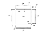
図2Aないし図2Cおよび図3に示すように、外装材12は、一対のライナシート部21、22と、これらライナシート部21、22を所定の間隙を隔てて平行に連結する複数のリブ状の連結部23とを有する、板状のプラスチック製段ボール素材20によって形成されている。
プラスチック製段ボール素材20は、フルートとライナシートを有する段ボール紙に類似する板状体をプラスチックにより形成したもので、段プラスチックとも呼ばれる。
一対のライナシート部21、22は、一定の間隙層24を隔てて平行に対面するプラスチック製のシート、例えば低比重で耐熱性および機械的強度に優れたポリプロピレン樹脂(PP)製のシートで、互いに同一の厚さおよび材質となっている。
複数のリブ状の連結部23は、ライナシート部21、22を一体に結合しつつ間隙層24を複数の帯状空間24aに分割する複数の略平行な壁部となっており、各ライナシート部21、22と略同一の厚さおよび同一の材質となっている。すなわち、複数の連結部23も、プラスチック製、例えばポリプロピレン樹脂(PP)製である。
このプラスチック製段ボール素材20は、例えば図2C中に断面で示す経路規制領域Z1のような梯子状の断面形状になるように一様に押出し成形された後、所定の素材輪郭形状にカットされ、さらに厚さ方向に部分的な切込みあるいは切除を施す二次加工がなされたものである。
複数のリブ状の連結部23は、互いに平行に延在しており、図2Bおよび図2Cに示すように、これら連結部23の延在方向のみならず、複数の連結部23の横断面も完全に平行になっている。
ただし、複数のリブ状の連結部23の横断面は、平行でなくてもよい。すなわち、隣り合う各一対の連結部23の横断面が互いに逆方向に傾斜し、かつ、複数の連結部23の横断面が交互にその傾斜方向を逆転させるようになっていてもよい。具体的には、隣り合う各一対の連結部23の横断面がライナシート部21、22のうちいずれか一方側で接近しいずれか他方側で離間するように略「ハ」の字形に傾斜することで、複数の連結部23が全体として段ボールのフルートに近い波形断面形状をなすように構成してもよい。
図1および図3に示すように、外装材12は、プラスチック製段ボール素材20を複数のリブ状の連結部23が周方向に延びる状態で多角筒状に屈曲させた筒状体となっており、内部空間12cを形成する多角形の横断面形状、例えば四角形(長方形または正方形)の横断面形状を有している。
また、多角筒状の外装材12の軸方向の一部の領域、例えば図2C中に断面で示す伸縮および曲げ許容領域Z2においては、外周側のライナシート部21または/および内周側のライナシート部22が、隣り合うリブ状の連結部23の間で部分的にスリット状に切除されている。そして、外装材12の外周面12aおよび内周面12bのうち少なくとも一方が、部分的に矩形波状(波形)の縦断面形状をなしている。
具体的には、図3ないし図5に示すように、外装材12の軸方向の略全域にわたり、平行リブ状の連結部23は、外装材12の多角筒状の角部に対応する周方向の複数箇所で、それぞれ切断されている。
また、伸縮および曲げ許容領域Z2内で隣り合う各一対の連結部23の間では、外周面12a側のライナシート部21または内周面12b側のライナシート部22のいずれか一方が、部分的に周方向に延びるスリット状に切除され、外周面12a側のライナシート部21または内周面12b側のライナシート部22のいずれか他方が、周方向に連続して形成されている。
そして、外装材12の多角形横断面の各辺に対応する各面において、外周面12aおよび内周面12bのうち少なくとも一方が、部分的に波形の縦断面形状をなしている。
したがって、外装材12の伸縮および曲げ許容領域Z2における外周面12aおよび内周面12bのうち一方(片方)が部分的に波形の縦断面形状をなす部分では、他方(他の片方)は、全体的に平坦な縦断面形状をなすことになるが、ここでは、伸縮および曲げ許容領域Z2の全域で外周面12aおよび内周面12bのうち両方が部分的に波形の縦断面形状をなす場合について説明する。
伸縮および曲げ許容領域Z2に対応する外装材12の軸方向の一部の領域においては、外周面12aおよび内周面12bのうち両方が部分的に波形の縦断面形状をなしており、外周面12a側のライナシート部21がスリット状に切除された部分と、外周面12a側のライナシート部21が両側端部を一対の連結部23に支持された帯状に残された部分とが、交互に配置されている。
また、この伸縮および曲げ許容領域Z2内において、内周面12b側のライナシート部22は、外周面12a側のライナシート部21が周方向に延びるスリット状に切除された軸方向区間内で周方向に連続して形成されるとともに、その両側端部で隣り合う各一対の連結部23を一体に結合するように配置されている。
そして、伸縮および曲げ許容領域Z2内における外周面12a側のライナシート部21の一部と内周面12b側のライナシート部22の一部とが、交互に全周にわたって切除されつつ、全体として、外装材12の多角形横断面の各辺に対応する各面で矩形波状の縦断面形状をなしている。したがって、伸縮および曲げ許容領域Z2において、外装材12は、蛇腹に類似する形状となり、良好な屈曲性および伸縮性が得られるものとなっている。
外装材12は、さらに、経路規制領域Z1にまたは伸縮および曲げ許容領域Z2に隣接する比較的低曲げ剛性の薄肉領域Z3を有している。
この薄肉領域Z3においては、外周面12a側のライナシート部21または内周面12b側のライナシート部22のいずれか一方と、連結部23とが切除されており、外周面12a側または内周面12b側のライナシート部21、22のいずれか他方のみ、例えば内周面12b側のライナシート部22のみで、薄肉領域Z3が構成されている。
なお、上述の説明において、スリット状の切除は、隣り合う一対のリブ状の連結部23の間に位置する外周面12a側のライナシート部21または内周面12b側のライナシート部22を切除するスリット幅が狭く、隣り合う一対のリブ状の連結部23の間に外周面12a側のライナシート部21または内周面12b側のライナシート部22が残る場合を含むが、その残り部分が相互に干渉しない程度であるのがよい。
また、図2Aに示すように、プラスチック製段ボール素材20には、前記二次加工時に、筒状に屈曲させた両端部を相互に接続するための接着代部分25が設けられるが、同図中に仮想線で示すように、前述のスリット状の切除時にその切除部分が接着代部分25に及んで形成されてもよい。
次に、作用について説明する。
上述のように構成された本実施形態のワイヤーハーネスにおいては、板状のプラスチック製段ボール素材20から、軸方向の一部の領域でその外周面12aまたは/および内周面12bを波形の縦断面形状にした多角筒状の外装材12を容易に作製できる。
そして、その外装材12の伸縮および曲げ許容領域Z2においては、外周面12aおよび内周面12bのうち少なくとも一方が部分的に波形の縦断面形状をなすように、ライナシート部21、22の一部を切除されているので、低曲げ剛性となっている。
一方、軸方向の残部である経路規制領域Z1においては、外装材12の一対のライナシート部21、22がそれぞれ軸方向に連続するとともに並列する複数のリブ状の連結部23で互いに連結されているので、高曲げ剛性となる。
また、薄肉領域Z3は、外装材12の片面側のライナシート部22が軸方向および周方向に連続する角筒状をなしているので、波形の縦断面形状をなす伸縮および曲げ許容領域Z2よりは相対的に高剛性となり、経路規制領域Z1よりは相対的に低剛性となる。
さらに、外装材12の軸方向における経路規制領域Z1の長さ、伸縮および曲げ許容領域Z2の長さ、および、薄肉領域Z3の長さは、二次加工の範囲に応じて適宜設定できる。したがって、伸縮や曲げが要求される外装材12の軸方向の一部区間においては、伸縮および曲げ許容領域Z2により伸縮や曲げの許容機能を発揮させ、電線群11の経路規制が要求される他の区間においては、経路規制領域Z1により所要の経路規制機能を発揮させることができる。
加えて、薄肉領域Z3により外径または内径を部分的に変化させたり、経路規制区間の途中でわずかな撓みや屈曲を吸収させたり、経路規制領域Z1と伸縮および曲げ許容領域Z2との間に適度の剛性調整区間を設定したりすることもできる。
また、外装材12は、プラスチック製段ボール素材を用いているので、吸水することがなく、被水領域内に配置しても排水性に優れたものとなる。さらに、プラスチック製段ボール素材20は、通い箱や床面養生シート等に多用される一般的なプラスチック製段ボールから作製できるので、外装材12を低コストに製造できる。
このように、本実施形態においては、外装材12の外周面12aおよび内周面12bのうち少なくとも一方側でライナシート部21、22の一部をスリット状に切除する二次加工を行うだけで、軸方向の一部に伸縮および曲げ許容領域Z2を、他の区間に経路規制領域Z1を形成できる。したがって、外装材12の外装区間内において要求される経路規制機能と伸縮や曲げの許容機能とを容易に両立させることができる。しかも、プラスチック製段ボール素材20を用いて外装材12を形成するので、被水領域内に配置しても排水性に優れた軽量で低コストの外装材12を備えたワイヤーハーネス10を提供できる。
(第2の実施の形態)
図6は、本発明の他の実施の形態に係るワイヤーハーネスを示している。
図6は、本発明の他の実施の形態に係るワイヤーハーネスを示している。
なお、本実施形態は、上述の第1の実施の形態に外装材12に代わる外装材32を設ける点で第1の実施の形態と相違するが、その他の構成は、上述の第1の実施の形態と略同様であるので、以下、同一または類似構成部分については、第1の実施の形態の対応する構成要素の符号を用いて説明する。
図6に示すように、本実施形態において、ワイヤーハーネス10の電線11に外装される外装材32は、その外周面32a側となるプラスチック製段ボール素材20の片面側のライナシート21を残して、内周面32bとなる他面側から略V字形の溝を形成した後、プラスチック製段ボール素材20を筒状に屈曲させて、外周面32a側の図示しない接着代部分で接合させたもので、電線群11を挿通可能な内部空間32cを形成している。
そして、外装材32の軸方向の一部が伸縮および曲げ許容領域Z2となっており、外装材32の伸縮および曲げ許容領域Z2内において、外周面32aおよび内周面32bのうち両方が部分的に波形の縦断面形状をなしている。そして、外装材32の外周面32a側のライナシート部21がスリット状に切除された部分と、外周面32a側のライナシート部21が両側端部を一対の連結部23に連結されつつ帯状に残された部分とが、交互に配置されている。
また、内周面12b側のライナシート部22は、多角筒状の角部に対応する複数箇所で切断される一方、外周面32a側のライナシート部21が周方向に延びるスリット状に切除された軸方向区間内ではその両側の連結部23の間に連続して形成され、外周面32a側のライナシート部21が帯状に残された部分に対応する区間では、スリット状に切除されている。
すなわち、外装材32の伸縮および曲げ許容領域Z2においては、外周面32a側のライナシート部21の一部と内周面32b側のライナシート部22の一部とが、交互に全周にわたって切除されつつ、全体として、外装材32の多角形横断面の各辺に対応する各面で矩形波状の縦断面形状をなしている。したがって、外装材32は、蛇腹に類似する形状となり、良好な屈曲性および伸縮性が得られるものとなっている。
本実施形態においても、外装材12の外周面12aおよび内周面12bのうち少なくとも一方側でライナシート部21、22の一部をスリット状に切除する二次加工を行うだけで、軸方向の一部に伸縮および曲げ許容領域Z2を、他の区間に経路規制領域Z1を形成できる。したがって、外装材12の外装区間内において要求される経路規制機能と伸縮や曲げの許容機能とを容易に両立させることができる。また、プラスチック製段ボール素材20を用いて外装材12を形成しているので、被水領域内に配置しても排水性に優れた軽量で低コストの外装材12を備えたワイヤーハーネス10を提供することができる。
なお、上述の各実施の形態においては、外装材12、32は、四角形の横断面形状になっていたが、三角形でもよいし四角形以上の多角形の筒状であってもよく、正多角形断面を有するものである必要もない。
また、上述の各実施形態においては、伸縮および曲げ許容領域Z2の全域で外周面12aおよび内周面12bが波形の縦断面形状をなす場合について説明したが、伸縮および曲げ許容領域Z2の一部の軸方向区間において外周面12aおよび内周面12bのうち一方(片方)のみが波形の縦断面形状をなしていてもよい。
さらに、プラスチック製段ボール素材20にスリット状の切除部分を形成する際、リブ状の連結部23に沿って刃物を移動させ、機械的に容易に切断することができるが、単なる刃物での切断でなく、熱により溶断させてもよい。また、上述の各実施形態では外装材12、32は、1枚のプラスチック製段ボール素材20から作製されていたが、例えば外装材12の外径に対応する内径を有する外装材12と同様な構成を有するサイズ違いの外装材をさらに重ねてもよい。
以上説明したように、本発明は、経路規制機能と伸縮や曲げの許容機能とを容易に両立させることができ、かつ、被水領域内に配置しても排水性に優れた軽量で低コストの外装材を備えたワイヤーハーネスを提供することができるものであり、車両等に実装される外装材を備えたワイヤーハーネス全般に有用である。
10 ワイヤーハーネス
11 電線群
12、32 外装材
12a、32a 外周面
12b、32b 内周面
20 プラスチック製段ボール素材
21 ライナシート部(外周面側のライナシート部)
22 ライナシート部(内周面側のライナシート部)
23 連結部(リブ状の連結部)
24 間隙層
24a 帯状空間
25 接着代部分
Z1 経路規制領域(軸方向の残部)
Z2 伸縮および曲げ許容領域(軸方向の一部の領域)
Z3 薄肉領域
11 電線群
12、32 外装材
12a、32a 外周面
12b、32b 内周面
20 プラスチック製段ボール素材
21 ライナシート部(外周面側のライナシート部)
22 ライナシート部(内周面側のライナシート部)
23 連結部(リブ状の連結部)
24 間隙層
24a 帯状空間
25 接着代部分
Z1 経路規制領域(軸方向の残部)
Z2 伸縮および曲げ許容領域(軸方向の一部の領域)
Z3 薄肉領域
Claims (3)
- 電線群の長さ方向の特定区間を取り囲むよう該特定区間に外装された外装材を備えたワイヤーハーネスであって、
前記外装材が、所定の間隙層を隔てて平行に対面する一対のライナシート部と、両ライナシート部を一体に結合しつつ前記間隙層を複数に分割する複数のリブ状の連結部とを有するプラスチック製段ボール素材によって形成されるとともに、該プラスチック製段ボール素材を前記連結部が周方向に延びる多角筒状に屈曲させた筒状体となっており、
前記外装材の軸方向の一部の領域にて、前記ライナシート部の一部が隣り合う前記連結部の間で部分的にスリット状に切除され、前記筒状体の外周面および内周面のうち少なくとも一方が部分的に波形の縦断面形状をなしていることを特徴とするワイヤーハーネス。 - 前記多角筒状の角部に対応する前記周方向の複数箇所で、前記リブ状の前記連結部がそれぞれ切断される一方、
前記軸方向の一部の領域における前記内周面側または前記外周面側の前記ライナシート部が、前記周方向に連続していることを特徴とする請求項1に記載のワイヤーハーネス。 - 前記外装材の前記軸方向の一部の領域における前記外周面側の前記ライナシート部の一部と前記内周面側の前記ライナシート部の一部とが、交互に全周にわたって切除されていることを特徴とする請求項1または2に記載のワイヤーハーネス。
Applications Claiming Priority (2)
| Application Number | Priority Date | Filing Date | Title |
|---|---|---|---|
| JP2015-030595 | 2015-02-19 | ||
| JP2015030595A JP2016152749A (ja) | 2015-02-19 | 2015-02-19 | ワイヤーハーネス |
Publications (1)
| Publication Number | Publication Date |
|---|---|
| WO2016133018A1 true WO2016133018A1 (ja) | 2016-08-25 |
Family
ID=56689267
Family Applications (1)
| Application Number | Title | Priority Date | Filing Date |
|---|---|---|---|
| PCT/JP2016/054129 Ceased WO2016133018A1 (ja) | 2015-02-19 | 2016-02-12 | ワイヤーハーネス |
Country Status (2)
| Country | Link |
|---|---|
| JP (1) | JP2016152749A (ja) |
| WO (1) | WO2016133018A1 (ja) |
Families Citing this family (3)
| Publication number | Priority date | Publication date | Assignee | Title |
|---|---|---|---|---|
| JP7349157B2 (ja) * | 2018-08-03 | 2023-09-22 | 株式会社ニックス | ケーブル支持体 |
| CN112421523B (zh) * | 2020-11-23 | 2022-03-08 | 济南新材料产业技术研究院 | 一种拱桥式波形敷设的桥架及装配方法 |
| JP7726009B2 (ja) * | 2021-10-21 | 2025-08-20 | 住友電装株式会社 | プロテクタ |
Citations (5)
| Publication number | Priority date | Publication date | Assignee | Title |
|---|---|---|---|---|
| JPH06340015A (ja) * | 1993-06-02 | 1994-12-13 | Nippon Petrochem Co Ltd | ヒンジを有するプラスチック段ボール及びその製造方法 |
| JP2014117099A (ja) * | 2012-12-11 | 2014-06-26 | Yazaki Corp | ワイヤハーネス |
| JP2014204582A (ja) * | 2013-04-08 | 2014-10-27 | 矢崎総業株式会社 | ハーネスプロテクタ |
| WO2015016056A1 (ja) * | 2013-08-02 | 2015-02-05 | 株式会社オートネットワーク技術研究所 | プロテクタ付ワイヤーハーネス、プロテクタ付ワイヤーハーネスの製造方法、プロテクタ組立用治具及びプロテクタ |
| JP2015126672A (ja) * | 2013-12-27 | 2015-07-06 | 株式会社オートネットワーク技術研究所 | プロテクタ、電線モジュール、およびプロテクタの製造方法 |
-
2015
- 2015-02-19 JP JP2015030595A patent/JP2016152749A/ja active Pending
-
2016
- 2016-02-12 WO PCT/JP2016/054129 patent/WO2016133018A1/ja not_active Ceased
Patent Citations (5)
| Publication number | Priority date | Publication date | Assignee | Title |
|---|---|---|---|---|
| JPH06340015A (ja) * | 1993-06-02 | 1994-12-13 | Nippon Petrochem Co Ltd | ヒンジを有するプラスチック段ボール及びその製造方法 |
| JP2014117099A (ja) * | 2012-12-11 | 2014-06-26 | Yazaki Corp | ワイヤハーネス |
| JP2014204582A (ja) * | 2013-04-08 | 2014-10-27 | 矢崎総業株式会社 | ハーネスプロテクタ |
| WO2015016056A1 (ja) * | 2013-08-02 | 2015-02-05 | 株式会社オートネットワーク技術研究所 | プロテクタ付ワイヤーハーネス、プロテクタ付ワイヤーハーネスの製造方法、プロテクタ組立用治具及びプロテクタ |
| JP2015126672A (ja) * | 2013-12-27 | 2015-07-06 | 株式会社オートネットワーク技術研究所 | プロテクタ、電線モジュール、およびプロテクタの製造方法 |
Also Published As
| Publication number | Publication date |
|---|---|
| JP2016152749A (ja) | 2016-08-22 |
Similar Documents
| Publication | Publication Date | Title |
|---|---|---|
| US20130056240A1 (en) | Wire protection member | |
| US9681594B2 (en) | Electromagnetic shielding member | |
| WO2018155135A1 (ja) | ワイヤーハーネス | |
| WO2016133018A1 (ja) | ワイヤーハーネス | |
| JP6354602B2 (ja) | 電線モジュール | |
| JP6950202B2 (ja) | 外装部材付電線 | |
| JP6314765B2 (ja) | 電線モジュール | |
| JP6323399B2 (ja) | 電線モジュール及び電線保護部材 | |
| JP6065828B2 (ja) | プロテクター及び電線モジュール | |
| WO2018030233A1 (ja) | ワイヤーハーネス | |
| JP6065830B2 (ja) | プロテクタ、電線モジュール、およびプロテクタの製造方法 | |
| JP6471454B2 (ja) | プロテクタ及び電線モジュール | |
| JP7416181B2 (ja) | 配線部材 | |
| JP2016165166A (ja) | 保護部材付電線の配設構造及び保護部材付電線 | |
| JP2016081823A (ja) | 電線モジュール | |
| JP2017050986A (ja) | プロテクタ、ワイヤーハーネス及びワイヤーハーネスの製造方法 | |
| WO2016158400A1 (ja) | 電線モジュール及び電線モジュール製造方法 | |
| JP6034706B2 (ja) | 外装材 | |
| JP2016119785A (ja) | 保護部材付電線及び保護部材 | |
| WO2017018164A1 (ja) | 電線外装体、ワイヤーハーネス、および罫線刃 | |
| JP2015156735A (ja) | 電線モジュール | |
| WO2017183520A1 (ja) | 外装部材付電線 | |
| WO2017018166A1 (ja) | 電線外装体、ワイヤーハーネス、および罫線刃 | |
| JP2017050980A (ja) | 外装部材、外装部材付電線及び外装部材付電線の製造方法 | |
| JP2022011633A (ja) | ワイヤーハーネスの保護構造 |
Legal Events
| Date | Code | Title | Description |
|---|---|---|---|
| 121 | Ep: the epo has been informed by wipo that ep was designated in this application |
Ref document number: 16752404 Country of ref document: EP Kind code of ref document: A1 |
|
| NENP | Non-entry into the national phase |
Ref country code: DE |
|
| 122 | Ep: pct application non-entry in european phase |
Ref document number: 16752404 Country of ref document: EP Kind code of ref document: A1 |