WO2016129743A1 - 저진동 특성을 가지는 자동차용 인터쿨러 파이프 - Google Patents
저진동 특성을 가지는 자동차용 인터쿨러 파이프 Download PDFInfo
- Publication number
- WO2016129743A1 WO2016129743A1 PCT/KR2015/003184 KR2015003184W WO2016129743A1 WO 2016129743 A1 WO2016129743 A1 WO 2016129743A1 KR 2015003184 W KR2015003184 W KR 2015003184W WO 2016129743 A1 WO2016129743 A1 WO 2016129743A1
- Authority
- WO
- WIPO (PCT)
- Prior art keywords
- intercooler pipe
- pipe
- intercooler
- connector
- vibration
- Prior art date
Links
Images


Classifications
-
- F—MECHANICAL ENGINEERING; LIGHTING; HEATING; WEAPONS; BLASTING
- F02—COMBUSTION ENGINES; HOT-GAS OR COMBUSTION-PRODUCT ENGINE PLANTS
- F02B—INTERNAL-COMBUSTION PISTON ENGINES; COMBUSTION ENGINES IN GENERAL
- F02B29/00—Engines characterised by provision for charging or scavenging not provided for in groups F02B25/00, F02B27/00 or F02B33/00 - F02B39/00; Details thereof
- F02B29/04—Cooling of air intake supply
- F02B29/045—Constructional details of the heat exchangers, e.g. pipes, plates, ribs, insulation, materials, or manufacturing and assembly
- F02B29/0475—Constructional details of the heat exchangers, e.g. pipes, plates, ribs, insulation, materials, or manufacturing and assembly the intake air cooler being combined with another device, e.g. heater, valve, compressor, filter or EGR cooler, or being assembled on a special engine location
-
- F—MECHANICAL ENGINEERING; LIGHTING; HEATING; WEAPONS; BLASTING
- F02—COMBUSTION ENGINES; HOT-GAS OR COMBUSTION-PRODUCT ENGINE PLANTS
- F02M—SUPPLYING COMBUSTION ENGINES IN GENERAL WITH COMBUSTIBLE MIXTURES OR CONSTITUENTS THEREOF
- F02M35/00—Combustion-air cleaners, air intakes, intake silencers, or induction systems specially adapted for, or arranged on, internal-combustion engines
- F02M35/10—Air intakes; Induction systems
- F02M35/10091—Air intakes; Induction systems characterised by details of intake ducts: shapes; connections; arrangements
- F02M35/10137—Flexible ducts, e.g. bellows or hoses
-
- F—MECHANICAL ENGINEERING; LIGHTING; HEATING; WEAPONS; BLASTING
- F02—COMBUSTION ENGINES; HOT-GAS OR COMBUSTION-PRODUCT ENGINE PLANTS
- F02M—SUPPLYING COMBUSTION ENGINES IN GENERAL WITH COMBUSTIBLE MIXTURES OR CONSTITUENTS THEREOF
- F02M35/00—Combustion-air cleaners, air intakes, intake silencers, or induction systems specially adapted for, or arranged on, internal-combustion engines
- F02M35/10—Air intakes; Induction systems
- F02M35/10091—Air intakes; Induction systems characterised by details of intake ducts: shapes; connections; arrangements
- F02M35/10144—Connections of intake ducts to each other or to another device
-
- F—MECHANICAL ENGINEERING; LIGHTING; HEATING; WEAPONS; BLASTING
- F02—COMBUSTION ENGINES; HOT-GAS OR COMBUSTION-PRODUCT ENGINE PLANTS
- F02M—SUPPLYING COMBUSTION ENGINES IN GENERAL WITH COMBUSTIBLE MIXTURES OR CONSTITUENTS THEREOF
- F02M35/00—Combustion-air cleaners, air intakes, intake silencers, or induction systems specially adapted for, or arranged on, internal-combustion engines
- F02M35/10—Air intakes; Induction systems
- F02M35/10242—Devices or means connected to or integrated into air intakes; Air intakes combined with other engine or vehicle parts
- F02M35/10268—Heating, cooling or thermal insulating means
-
- F—MECHANICAL ENGINEERING; LIGHTING; HEATING; WEAPONS; BLASTING
- F02—COMBUSTION ENGINES; HOT-GAS OR COMBUSTION-PRODUCT ENGINE PLANTS
- F02M—SUPPLYING COMBUSTION ENGINES IN GENERAL WITH COMBUSTIBLE MIXTURES OR CONSTITUENTS THEREOF
- F02M35/00—Combustion-air cleaners, air intakes, intake silencers, or induction systems specially adapted for, or arranged on, internal-combustion engines
- F02M35/10—Air intakes; Induction systems
- F02M35/1034—Manufacturing and assembling intake systems
- F02M35/10354—Joining multiple sections together
-
- F—MECHANICAL ENGINEERING; LIGHTING; HEATING; WEAPONS; BLASTING
- F16—ENGINEERING ELEMENTS AND UNITS; GENERAL MEASURES FOR PRODUCING AND MAINTAINING EFFECTIVE FUNCTIONING OF MACHINES OR INSTALLATIONS; THERMAL INSULATION IN GENERAL
- F16L—PIPES; JOINTS OR FITTINGS FOR PIPES; SUPPORTS FOR PIPES, CABLES OR PROTECTIVE TUBING; MEANS FOR THERMAL INSULATION IN GENERAL
- F16L11/00—Hoses, i.e. flexible pipes
- F16L11/14—Hoses, i.e. flexible pipes made of rigid material, e.g. metal or hard plastics
- F16L11/15—Hoses, i.e. flexible pipes made of rigid material, e.g. metal or hard plastics corrugated
-
- F—MECHANICAL ENGINEERING; LIGHTING; HEATING; WEAPONS; BLASTING
- F16—ENGINEERING ELEMENTS AND UNITS; GENERAL MEASURES FOR PRODUCING AND MAINTAINING EFFECTIVE FUNCTIONING OF MACHINES OR INSTALLATIONS; THERMAL INSULATION IN GENERAL
- F16L—PIPES; JOINTS OR FITTINGS FOR PIPES; SUPPORTS FOR PIPES, CABLES OR PROTECTIVE TUBING; MEANS FOR THERMAL INSULATION IN GENERAL
- F16L9/00—Rigid pipes
- F16L9/12—Rigid pipes of plastics with or without reinforcement
- F16L9/127—Rigid pipes of plastics with or without reinforcement the walls consisting of a single layer
-
- F—MECHANICAL ENGINEERING; LIGHTING; HEATING; WEAPONS; BLASTING
- F02—COMBUSTION ENGINES; HOT-GAS OR COMBUSTION-PRODUCT ENGINE PLANTS
- F02M—SUPPLYING COMBUSTION ENGINES IN GENERAL WITH COMBUSTIBLE MIXTURES OR CONSTITUENTS THEREOF
- F02M35/00—Combustion-air cleaners, air intakes, intake silencers, or induction systems specially adapted for, or arranged on, internal-combustion engines
- F02M35/10—Air intakes; Induction systems
- F02M35/10314—Materials for intake systems
- F02M35/10321—Plastics; Composites; Rubbers
-
- F—MECHANICAL ENGINEERING; LIGHTING; HEATING; WEAPONS; BLASTING
- F02—COMBUSTION ENGINES; HOT-GAS OR COMBUSTION-PRODUCT ENGINE PLANTS
- F02M—SUPPLYING COMBUSTION ENGINES IN GENERAL WITH COMBUSTIBLE MIXTURES OR CONSTITUENTS THEREOF
- F02M35/00—Combustion-air cleaners, air intakes, intake silencers, or induction systems specially adapted for, or arranged on, internal-combustion engines
- F02M35/10—Air intakes; Induction systems
- F02M35/1034—Manufacturing and assembling intake systems
- F02M35/10347—Moulding, casting or the like
-
- Y—GENERAL TAGGING OF NEW TECHNOLOGICAL DEVELOPMENTS; GENERAL TAGGING OF CROSS-SECTIONAL TECHNOLOGIES SPANNING OVER SEVERAL SECTIONS OF THE IPC; TECHNICAL SUBJECTS COVERED BY FORMER USPC CROSS-REFERENCE ART COLLECTIONS [XRACs] AND DIGESTS
- Y02—TECHNOLOGIES OR APPLICATIONS FOR MITIGATION OR ADAPTATION AGAINST CLIMATE CHANGE
- Y02T—CLIMATE CHANGE MITIGATION TECHNOLOGIES RELATED TO TRANSPORTATION
- Y02T10/00—Road transport of goods or passengers
- Y02T10/10—Internal combustion engine [ICE] based vehicles
- Y02T10/12—Improving ICE efficiencies
Definitions
- the present invention relates to an automotive intercooler pipe, and more particularly, to change the mass by varying the thickness of the intercooler pipe in order to effectively prevent the vibration of the throttle body from being transmitted to the side members of the intercooler and the vehicle body through the intercooler pipe.
- varying the rigidity of the pipe material by changing the material of the pipe, by increasing the impedance change of the intercooler pipe to reflect the traveling wave of the vibration to reduce the vibration transmitted through the intercooler pipe will be.
- the air flowing from the outside of the vehicle is compressed through a turbo device, cooled through an intercooler, and then introduced into the engine.
- An intercooler pipe for a vehicle is a pipe connected between an intercooler and a throttle body of an engine.
- the intercooler pipe performs a flow path function of transferring air cooled in the intercooler to the throttle body of the engine.
- FIG. 1 illustrates a structure of a conventional automotive intercooler pipe.
- the inlet side rubber tube 2 is installed on the inlet of the tubular body 1 made of aluminum, and the outlet side rubber tube 3 is installed on the outlet of the tubular body 1, and the rubber tubes 2 3) is a structure in which the clamp 4 is fixed.
- the conventional automotive intercooler pipe as described above has a disadvantage in that the cost is increased and the weight is increased because the aluminum tube and the rubber tube are used.
- an intercooler pipe in which the entire intercooler pipe is formed of a plastic material using a thermoplastic ether ester elastomer (TEEE) has been introduced.
- TEEE thermoplastic ether ester elastomer
- the plastic intercooler pipe has a problem that it is difficult to apply to an automobile due to the deterioration of vibration and noise compared to the conventional intercooler pipe shown in FIG. 1.
- the structure and arrangement of power trains are different depending on the vehicle type in passenger vehicles.However, the method of supporting the engine and transmission to the car body among the power trains is largely (the main points of connection between power trains and the car body).
- the four-point mounting method, which consists of these four places, and the three-point mounting method, which consists of three main points of connection between the power train and the body, are mainly applied.
- the three-point mounting method which is widely used in small and medium-sized vehicles, and its application field is gradually expanding, has relatively greater rolling of the engine than the four-point mounting method. Accordingly, in the vehicle to which the three-point mounting is applied, there is a problem that the noise and vibration transmitted through the intercooler pipe may be greater, and a solution for this is required.
- the present invention was devised to solve the above-mentioned conventional problems, and the vibration and noise performance of the entire pipe is made of plastic, but the vibration and noise performance can be achieved at the same level or better than the conventional intercooler pipe.
- an intercooler is allowed to slip at a connection part according to the engine's behavior and to secure flexibility in specific directions (directions in which the throttle body vibrates mainly).
- the intercooler pipe for automobiles having the low vibration characteristic of the present invention may effectively prevent the vibration of the throttle body from being transmitted to the side members of the intercooler and the vehicle body through the intercooler pipe.
- the mass and varying the rigidity by varying the material of the pipe, it is characterized by the configuration of reducing the vibration transmitted through the intercooler pipe by increasing the amount of impedance change of the interclocker pipe to reflect the traveling wave of vibration.
- Automotive intercooler pipe having a low vibration characteristic of the present invention having the configuration as described above is formed by different thicknesses and materials between the upper and lower folds and the middle portion, the transfer from the throttle body according to the effect of mass impedance and rigid impedance Vibration is attenuated, resulting in an excellent effect of reducing vehicle noise and vibration.
- the intercooler pipe rotates (slips) according to the behavior of the engine, thereby transmitting vibrations generated in the engine and suppressing noise generated by the intercooler pipe in the conventional structure.
- a cutoff portion is formed to further adjust flexibility in a specific direction to block the contact between the intercooler pipe and the peripheral parts, and the cutoff portion is disposed along the first and second rows spaced apart from each other, such that the front and rear directions as well as the left and right directions are vertically disposed. It has the advantage of allowing the rotation of the intercooler pipe to more effectively dampen the vibration occurring in the direction.
- the intercooler pipe of the present invention adjusts the characteristics of the reflected wave with respect to the traveling wave by varying the material and / or length of the intermediate part by applying the mass and stiffness mismatch structure as described above, according to the vehicle model to which the present invention intercooler pipe is applied.
- the effect of tuning to reduce vibration and noise in a specific frequency region has been obtained.
- FIG. 1 is a perspective view of a conventional intercooler pipe
- FIG. 2 is a partial cutaway perspective view of the present invention intercooler pipe
- FIG. 3 is a side view of the upper side of the present invention intercooler pipe
- Figure 4 is an enlarged partial cutaway perspective view of the main part of the present invention intercooler pipe
- 6 and 7 are graphs of the noise level according to the engine speed of the present invention intercooler pipe
- FIG. 8 is a view illustrating a state in which a throttle body and the throttle body and the intercooler pipe are coupled through a connector according to a preferred embodiment of the present invention
- FIG. 9 is a cross-sectional view of a portion in which the throttle body and the intercooler pipe are coupled to each other in FIG. 8.
- the reason why the plastic intercooler pipe is vulnerable to vibration and noise is that the vibration transmitted from the engine is transmitted to the intercooler through the intercooler pipe and the vibration transmitted to the intercooler vibrates the side members of the vehicle body. This causes vibration and noise in the room. This phenomenon causes the traveling wave of the vibration transmitted from the engine to pass through the medium (pipe) with little loss of traveling wave to the pipe medium made of the same material so that the vibration is hardly attenuated. Because it becomes.
- the present inventors form the inlet and outlet portions of the pipe with different kinds of synthetic resin materials, respectively, rather than forming the entire pipe with the same material, and further, the thicknesses of the inlet and outlet portions and the middle portion are mutually different.
- the structure of the intercooler pipe of different concept was conceived.
- the intercooler pipe of the present invention originated from the above concept is that when the traveling wave of the vibration transmitted from the engine enters the middle part from the inlet part, the medium is different from the medium by passing the medium and the medium part of the inlet part having different materials and thicknesses. As the reflected wave with respect to the traveling wave of the vibration is formed, the traveling wave component of the vibration due to the superposition of the traveling wave and the reflected wave disappears and the vibration is attenuated.
- the traveling wave of the vibration passes through the outlet portion from the middle portion, the reflected wave is formed to the traveling wave of the vibration due to the difference of the medium by passing through the medium of the middle portion and the outlet portion of the material having different thicknesses.
- the traveling wave component of the vibration due to mutual overlap of the reflected waves disappears, the vibration is further attenuated, and the traveling wave component of the vibration disappears over at least two times, so that the vibration is also attenuated.
- Figure 2 is a partially cutaway perspective view of the present invention intercooler pipe
- Figure 3 is an upper side side view of the present invention intercooler pipe
- Figure 4 is an enlarged partial cutaway perspective view of the main portion of the present invention intercooler pipe.
- the thickness and the material of the intercooler pipe for each section of the pipe is characterized by a configuration that is formed differently.
- the intercooler pipe 10 of the present invention has a rib from an inlet 14 of an intercooler pipe located above and a surface of a tubular body 11 extending in the direction of the inlet 14.
- the upper wrinkle portion 30 forming the upper wrinkle body 12 protruding in a rib shape
- the outlet 15 of the intercooler pipe located below
- the surface of the tube body 11 extending in the direction of the outlet 15.
- a lower wrinkle portion 31 that forms a lower wrinkle body 13 protruding in a rib shape from the pipe body 11 that is bent downward from the upper wrinkle part 30 and connected to the lower wrinkle part 31. It is comprised including the intermediate part 20 provided.
- the upper corrugated body 12 and the lower corrugated body 13 is formed to protrude in a ring shape on the surface along the circumference of the intercooler pipe 10, but the protrusion height is different It has a cutout 16 formed (not having a lower or partially protruding height).
- the flexibility of the intercooler pipe 10 is relatively lowered (relatively increased in rigidity) in the direction in which the cutout portion 16 is formed, thereby limiting warpage.
- Formation of the break 16 as described above has the effect that the force required when the intercooler pipe 10 is bent in a specific direction and the force required when it is bent in a different direction.
- the cutout portions 16 are arranged to form a straight line along the longitudinal direction of the intercooler pipe 10. As shown in FIG. 3, the slip of the intercooler pipe 10 is reduced. It may be arranged in a straight line deviated from each other so as to have a plurality of specific directions that are induced or the bending of the upper corrugated body 12 and the lower corrugated body 13 is induced.
- the rows formed by the cutout portions 16 are arranged in the first row A and the second row B adjacent to each other along the longitudinal direction on the upper and lower corrugations 12 and 13.
- the first row A and the second row B are formed at positions spaced apart from each other along the circumference of the upper and lower corrugations 12.
- the rigidity of the intercooler pipe 10 may be further increased through the formation of the disconnection portion 16, but the flexibility may be increased in a direction in which vibration is mainly generated, thereby suppressing noise and vibration more efficiently.
- first row A and the second row B on which the cutout portions 16 are disposed are disposed in the front-back direction and the vertical direction (or the left-right direction) (based on the vehicle body), respectively, and have different vibration frequencies. They can insulate them more efficiently and have an effect of inducing slip of the intercooler pipe 10.
- the vibration is caused by the intercooler pipe made of a plastic material due to the impedance characteristic of the medium for transmitting the vibration.
- the shape of the medium for transmitting vibration is constant or the material of the same medium is the same material, the amount of change in impedance is small, so the vibration is easily transmitted.
- the amount of change in the impedance of the medium is linked to the amount of change in the mass, stiffness and damping of the medium.
- the intercooler pipe of the present invention proposes a mass impedance mismatch structure that changes the thickness of a tube for each section.
- the thickness d1 of the tubular body 11 of the middle portion 20 is the thickness d2 and the bottom wrinkle portion 31 of the upper wrinkled body 12 of the upper wrinkled part 30. It is formed to be thicker than the thickness (d3) of the lower corrugated body 13 of the mass of the middle portion 20 is formed to be heavier than the mass of the upper wrinkle portion 30 and the lower wrinkle portion (31).
- the masses of the upper wrinkle portion 30 and the lower wrinkle portion 31 are varied so that the mass between the upper wrinkle portion 30 and the middle portion 20 and between the middle portion 20 and the lower wrinkle portion 31, respectively. Impedance mismatch occurs, which causes the traveling wave between the excitation point and the receiving point to be reflected to reduce the vibration transmitted through the intercooler pipe.
- the thicknesses d2 and d3 of the upper and lower corrugations 12 and 13 are formed to be 1.3 mm, respectively, and the thickness d1 of the tubular body 11 of the intermediate part 20 is formed. ) was formed to 5 mm.
- the intercooler pipe of the present invention uses a rigid impedance mismatch structure using materials having different stiffnesses for each section of the pipe, and a heterogeneous large difference in storage modulus for each section of the pipe.
- the upper wrinkle portion 30 and the lower wrinkle portion 31 using a synthetic resin material of a soft material, the middle portion 20 by using a synthetic resin of a hard material, the upper wrinkle portion 30 and the middle portion
- the difference in storage ratio between the 20 and between the middle portion 20 and the lower wrinkled portion 31 is given so that a rigid impedance mismatch effect occurs.
- the upper wrinkle portion 30 and the lower wrinkle portion 31 is made of a polyester-based (PET) synthetic resin of a soft material
- the middle portion 20 is a poly material of a hard material
- Butylene terephthalate (PBT) synthetic resin was used, and more specifically, the soft material employed in the upper wrinkle portion 30 and the lower wrinkle portion 31 is a dicarboxylate-Diol polymer
- a thermoplastic polyester elastomer (TPC-ET) resin made of a Glycol polymer
- the hard material employed in the intermediate portion 20 is polybutylene terephthalate (PBT).
- a thermoplastic polyester resin was used.
- the intercooler pipe of the present invention by varying the material and / or length of the intermediate portion 20 by applying a mass and stiffness mismatch structure as described above, by adjusting the characteristics of the reflected wave to the traveling wave, the intercooler pipe of the present invention According to the model to be applied to the effect that can perform tuning to reduce the vibration and noise in a specific frequency range.
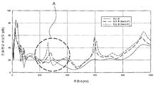
- Figure 5 is a graph of the vibration transmission loss according to the frequency of the intercooler pipe of the present invention
- Figure 6 and Figure 7 is a graph of the noise level according to the engine speed of the intercooler pipe of the present invention.
- the vibration transmission loss in the target frequency region A 200 to 450 Hz
- the vibration transmission loss is more distributed in the region 200-450 Hz, which is the target frequency range A, than when the thickness d1 of the middle part 20 is 3 mm.
- the large vibration transmission loss means that the vibration reduction is made larger.
- a microphone was mounted at the driver's ear position and acceleration driving noise and idle noise evaluation were conducted.
- the noise test results in idle when the booming frequency is shifted in the region of 100 Hz compared to the conventional intercooler pipe shown in FIG. 1. This phenomenon is explained by the shift of the resonant frequency due to the reduced weight compared to the existing intercooler pipe. In addition, the overall level of overall idle noise was tested to be equivalent to that of the conventional one.
- the intercooler pipe of the present invention is connected to the connector (so that the intercooler pipe rotates (slips) according to the behavior of the engine to transmit the vibration generated by the engine and to suppress the noise generated by the intercooler pipe in the conventional structure) 40) can be added.
- FIG. 8 is a view illustrating a state in which a throttle body and the throttle body and an intercooler pipe are coupled through a connector according to a preferred embodiment of the present invention
- FIG. 9 is a cross-sectional view of a portion in which the throttle body and the intercooler pipe are coupled in FIG. 8. to be.
- a conventional throttle body 50 has a tubular connection port 51 to be connected to the intercooler pipe 10, the outer peripheral surface of the connection port 51 as shown in Figure 8 Protruding from the surface to a predetermined height along the one side is formed with an inclined surface and the other side has a locking jaw 52 formed in a flat vertical plane (that is, the cross-section is serrated).
- the intercooler pipe 10 is connected to the connection port 51 in a state in which it is coupled with the connector 40.
- the connector 40 has a stopper 41, a portion of which can protrude from the inner circumferential surface of the connector 40.
- the stopper 41 is formed on the outer circumferential surface of the connection port 51. It is bitten by the protruding locking jaw 52 (the retraction is prevented when the stopper reaches the vertical plane through the inclined surface) and the fastening is performed.
- stopper 41 of the present embodiment prevents the connector 40 from being separated, but the connector 40 coupled with the intercooler pipe 10 is not clamped so as to prevent rotation from the connection port 51. Slip between the intercooler pipe 10 and the throttle body 50 is allowed.
- the same structure as the throttle body 50 has a connection port provided with a locking jaw in the intercooler, and the intercooler pipe 10 is coupled to the intercooler pipe 10 through the connector 40 of the present invention. Slip is also allowed between).
- the connector 40 is equipped with a rubber seal (42) to shield between the connector 40 and the connection port 51 when the connection with the connection port 51.
- the rubber chamber 42 may be mounted in another place (for example, a groove into which the stopper is fitted from the rear of the locking jaw in FIG. 9), but in the present invention, the rubber chamber 42 may be mounted in front of the locking jaw 52 (right in FIG. 9). At least one or more of the friction force between the rubber chamber 42 and the connector 40 or the friction force between the rubber chamber 42 and the connection port 51 is set small enough to allow the rotation of the connector 40. .
- the frictional force may be determined by manufacturing the rubber chamber 42 with a material having a small coefficient of friction or adjusting the gap between the rubber chamber 42 and the connector 40 or the rubber chamber 42 and the connection port 51. have.
- the intercooler pipe 10 of the present invention employing the connector 40 having the technical characteristics as described above can be more lighter than the conventional intercooler pipe and can reduce costs as well as reduce noise and vibration more efficiently. You can.
Landscapes
- Engineering & Computer Science (AREA)
- General Engineering & Computer Science (AREA)
- Mechanical Engineering (AREA)
- Chemical & Material Sciences (AREA)
- Combustion & Propulsion (AREA)
- Physics & Mathematics (AREA)
- Thermal Sciences (AREA)
- Manufacturing & Machinery (AREA)
- Rigid Pipes And Flexible Pipes (AREA)
- Cooling, Air Intake And Gas Exhaust, And Fuel Tank Arrangements In Propulsion Units (AREA)
Abstract
Description
Claims (9)
- 자동차의 인터쿨러 파이프에 있어서,상부에 위치한 인터쿨러 파이프의 입구(14)와, 상기 입구(14) 방향으로 연장된 관체(11)의 표면으로부터 리브 형상으로 돌출된 상부주름체(12)를 형성한 상부주름부(30)와, 하부에 위치한 인터쿨러 파이프의 출구(15)와, 상기 출구(15) 방향으로 연장된 관체(11)의 표면으로부터 리브 형상으로 돌출된 하부주름체(13)를 형성한 하부주름부(31)와, 상기 상부주름부(30)로부터 하방으로 절곡되어 상기 하부주름부(31)로 연결되는 관체(11)를 구비한 중간부(20)를 포함하여 구성되고,상기 중간부(20)의 관체(11) 두께(d1)를 상부주름부(30)의 상부주름체(12)의 두께(d2) 및 하부주름부(31)의 하부주름체(13)의 두께(d3)보다 더 크게 형성하고,상기 상부주름체(12)와 상기 하부주름체(13)에는 주름의 돌출 높이가 상이하게 형성된 단절부(16)가 각각 형성되는 구성을 특징으로 하는 자동차의 인터쿨러 파이프.
- 제 1 항에 있어서,상기 상부주름부(30) 및 상기 하부주름부(31)는 연질 소재의 합성수지재로 이루어지고,상기 중간부(20)는 경질 소재의 합성수지재로 이루어지는 것을 특징으로 하는 자동차의 인터쿨러 파이프.
- 제 2 항에 있어서,상기 상부주름부(30) 및 상기 하부주름부(31)는 폴리에스테르계(PET) 합성수지이고,상기 중간부(20)는 폴리부틸렌 테레프탈레이트계(PBT)의 합성수지인 것을 특징으로 하는 자동차의 인터쿨러 파이프.
- 제 3 항에 있어서,상기 상부주름부(30)와 하부주름부(31)의 연질 소재의 합성수지는 디카르복실레이트-디올(Dicarboxylate-Diol) 중합체와 클리콜(Glycol)중합체로 이루어진 열가소성 폴리에스터 엘라스토머(Thermoplastic polyester elastomer, TPC-ET) 합성수지인 것을 특징으로 하는 자동차의 인터쿨러 파이프.
- 제 3 항에 있어서,상기 중간부(20)에 채용된 경질 소재의 합성수지는 폴리부틸렌 테레프탈레이트(Polybutylene terephthalate, PBT)인 서모플라스틱폴리에스터(Thermoplastic polyester) 합성수지인 것을 특징으로 하는 자동차의 인터쿨러 파이프.
- 제 1 항에 있어서,상기 인터쿨러파이프가 특정 방향으로의 휘어질 때 요구되는 힘과 다른 방향으로 휘어질 때 요구되는 힘이 다르게 나타나도록 상기 단절부(16)가 인터쿨러파이프의 길이방향을 따라 직선형태의 열을 이루도록 배치되는 구성을 특징으로 하는 자동차의 인터쿨러 파이프.
- 제 6 항에 있어서,상기 단절부(16)들이 구성하는 열은 상기 상부주름체(12)와 상기 하부주름체(13) 상에서 길이방향을 따라 이웃하게 배치되는 적어도 두 개 이상의 열들로 구성되되, 각각의 열들은 상기 상부주름체(12)와 상기 하부주름체(13)의 둘레를 따라 서로 이격된 위치에서 형성된 것을 특징으로 하는 자동차의 인터쿨러 파이프.
- 제 1 항에 있어서,내주면에서 돌출되는 스토퍼(41)를 가지며 상기 인터쿨러파이프의 끝단에 결합되어 상기 인터쿨러파이프를 스로틀바디(50)의 연결포트(51)로 체결시키는 커넥터(40)를 구비하고,상기 커넥터(40)가 상기 연결포트(51)가 내측으로 진입되면 상기 스토퍼(41)가 연결포트(51)의 외주면에서 돌출된 걸림턱(52)에 물려져 체결이 이뤄지되, 상기 커넥터(40)는 연결포트(51)에서 인터쿨러파이프의 회전을 허용하는 작동을 수행하는 것을 특징으로 하는 자동차의 인터쿨러 파이프.
- 제 8 항에 있어서,상기 커넥터(40)에 연결포트(51)와의 체결시 커넥터(40)와 연결포트(51) 사이를 차폐시키는 러버실(42)이 장착되되,상기 러버실(42)과 상기 커넥터(40) 사이의 마찰력 또는 상기 러버실(42)과 상기 연결포트(51) 사이의 마찰력 중 적어도 어느 하나 이상은 상기 커넥터(40)의 회전이 허용될 만큼 작게 정해지는 것을 특징으로 하는 자동차의 인터쿨러 파이프.
Priority Applications (3)
| Application Number | Priority Date | Filing Date | Title |
|---|---|---|---|
| US15/550,598 US10385762B2 (en) | 2015-02-13 | 2015-03-31 | Car intercooler pipe having low vibration properties |
| DE112015006153.3T DE112015006153T5 (de) | 2015-02-13 | 2015-03-31 | Auto-Ladeluftschlauch mit geringen Vibrationseigenschaften |
| JP2017542155A JP6534744B2 (ja) | 2015-02-13 | 2015-03-31 | 低振動特性を有する自動車用インタークーラーパイプ |
Applications Claiming Priority (2)
| Application Number | Priority Date | Filing Date | Title |
|---|---|---|---|
| KR1020150021943A KR102215758B1 (ko) | 2015-02-13 | 2015-02-13 | 저진동 특성을 가지는 자동차용 인터쿨러 파이프 |
| KR10-2015-0021943 | 2015-02-13 |
Publications (1)
| Publication Number | Publication Date |
|---|---|
| WO2016129743A1 true WO2016129743A1 (ko) | 2016-08-18 |
Family
ID=56615320
Family Applications (1)
| Application Number | Title | Priority Date | Filing Date |
|---|---|---|---|
| PCT/KR2015/003184 WO2016129743A1 (ko) | 2015-02-13 | 2015-03-31 | 저진동 특성을 가지는 자동차용 인터쿨러 파이프 |
Country Status (5)
| Country | Link |
|---|---|
| US (1) | US10385762B2 (ko) |
| JP (1) | JP6534744B2 (ko) |
| KR (1) | KR102215758B1 (ko) |
| DE (1) | DE112015006153T5 (ko) |
| WO (1) | WO2016129743A1 (ko) |
Cited By (1)
| Publication number | Priority date | Publication date | Assignee | Title |
|---|---|---|---|---|
| US11225902B2 (en) * | 2019-08-15 | 2022-01-18 | Kohler Co. | Passive air cooling |
Families Citing this family (9)
| Publication number | Priority date | Publication date | Assignee | Title |
|---|---|---|---|---|
| DE102018111192A1 (de) * | 2018-05-09 | 2019-11-14 | Montaplast Gmbh | Luftleitung für Kraftfahrzeuge |
| US10895222B2 (en) * | 2018-05-22 | 2021-01-19 | Walbro Llc | Flow control valve for charge forming device |
| DE102018211151A1 (de) | 2018-07-06 | 2020-01-09 | Bayerische Motoren Werke Aktiengesellschaft | Lager für ein Kühlmodul |
| DE102020202580A1 (de) | 2020-02-28 | 2021-09-02 | Fränkische Industrial Pipes GmbH & Co. KG | Teilcorrugierte fluidleitung |
| DE102020205558A1 (de) | 2020-04-30 | 2021-11-04 | Etm Engineering Technologie Marketing Gmbh | Luftleitung für den Ansaugtrakt eines Verbrennungsmotors |
| CH717896A1 (de) * | 2020-09-23 | 2022-03-31 | Aborra Ag | Vorrichtung zum Entkoppeln sowie zur Schwingungskontrolle. |
| CN112832900A (zh) * | 2020-12-31 | 2021-05-25 | 山东艾泰克环保科技股份有限公司 | 一种商用车中冷器出气塑料管及其连续式注料生产线 |
| CN112879150A (zh) * | 2021-03-09 | 2021-06-01 | 广西玉柴机器股份有限公司 | 一种发动机中冷器出气管连接结构 |
| KR102463870B1 (ko) | 2021-08-06 | 2022-11-08 | 주식회사 메인터넌스 | 일체형 인터쿨러 호스 |
Citations (5)
| Publication number | Priority date | Publication date | Assignee | Title |
|---|---|---|---|---|
| JPH068384Y2 (ja) * | 1989-11-24 | 1994-03-02 | 東海ゴム工業株式会社 | ダクトホース |
| JP2002039450A (ja) * | 2000-07-27 | 2002-02-06 | Towa Buroo Kk | 蛇腹付ホース |
| JP2002257281A (ja) * | 2000-12-27 | 2002-09-11 | Toyoda Gosei Co Ltd | ホースの接続構造体 |
| KR20090002080U (ko) * | 2007-08-29 | 2009-03-04 | 김진국 | 스토퍼를 갖는 요철형 파이프용 연결구 |
| US20150042086A1 (en) * | 2013-08-12 | 2015-02-12 | Kia Motors Corporation | Mounting structure of intercooler pipe |
Family Cites Families (11)
| Publication number | Priority date | Publication date | Assignee | Title |
|---|---|---|---|---|
| KR0121651Y1 (ko) * | 1992-11-25 | 1998-08-01 | 이범창 | 차량용 엔진 흡기매니폴드의 공기흡입호오스 구조 |
| DE4330855C1 (de) * | 1993-09-11 | 1994-10-13 | Technoflow Tube Systems Gmbh | Verwendung eines Kunststoffrohres als crashgesicherte Kraftfahrzeug-Kraftstoffleitung |
| JP3211553B2 (ja) | 1994-04-28 | 2001-09-25 | 豊田合成株式会社 | 吸気ホース |
| JPH09177627A (ja) * | 1995-12-25 | 1997-07-11 | Toyoda Gosei Co Ltd | エアクリーナーホース及びその成形方法 |
| US5960977A (en) * | 1998-05-14 | 1999-10-05 | Itt Manufacturing Enterprises, Inc. | Corrugated polymeric filler neck tubing |
| DE10195908B4 (de) * | 2000-03-28 | 2007-03-29 | Asahi Kasei Kabushiki Kaisha | Blockcopolymer |
| JP2001348474A (ja) * | 2000-06-09 | 2001-12-18 | Nippon Zeon Co Ltd | ポリエステル系熱可塑性エラストマー組成物、それを含有する樹脂成形体および樹脂成形体の製造方法 |
| JP2002106761A (ja) * | 2000-10-04 | 2002-04-10 | Excel Kk | 蛇腹ダクト |
| KR20050029997A (ko) * | 2003-09-24 | 2005-03-29 | 쌍용자동차 주식회사 | 자동차용 과급기의 덕트구조 |
| CN103370527B (zh) * | 2010-12-22 | 2017-07-14 | 提克纳有限责任公司 | 具有复杂三维构造的高温导管 |
| EP2609941A1 (en) * | 2011-12-26 | 2013-07-03 | Laboratorios Sanifit, S.L. | Biocompatible implant |
-
2015
- 2015-02-13 KR KR1020150021943A patent/KR102215758B1/ko active IP Right Grant
- 2015-03-31 WO PCT/KR2015/003184 patent/WO2016129743A1/ko active Application Filing
- 2015-03-31 JP JP2017542155A patent/JP6534744B2/ja active Active
- 2015-03-31 DE DE112015006153.3T patent/DE112015006153T5/de active Pending
- 2015-03-31 US US15/550,598 patent/US10385762B2/en active Active
Patent Citations (5)
| Publication number | Priority date | Publication date | Assignee | Title |
|---|---|---|---|---|
| JPH068384Y2 (ja) * | 1989-11-24 | 1994-03-02 | 東海ゴム工業株式会社 | ダクトホース |
| JP2002039450A (ja) * | 2000-07-27 | 2002-02-06 | Towa Buroo Kk | 蛇腹付ホース |
| JP2002257281A (ja) * | 2000-12-27 | 2002-09-11 | Toyoda Gosei Co Ltd | ホースの接続構造体 |
| KR20090002080U (ko) * | 2007-08-29 | 2009-03-04 | 김진국 | 스토퍼를 갖는 요철형 파이프용 연결구 |
| US20150042086A1 (en) * | 2013-08-12 | 2015-02-12 | Kia Motors Corporation | Mounting structure of intercooler pipe |
Non-Patent Citations (1)
| Title |
|---|
| KIM, GI HWAN ET AL.: "Material NVH Convergence Technology for a Plastic Intercooler Pipe", SAE TECHNICAL PAPER # 2014-01-10 40, 1 April 2014 (2014-04-01) * |
Cited By (2)
| Publication number | Priority date | Publication date | Assignee | Title |
|---|---|---|---|---|
| US11225902B2 (en) * | 2019-08-15 | 2022-01-18 | Kohler Co. | Passive air cooling |
| US11905876B2 (en) | 2019-08-15 | 2024-02-20 | Kohler Co. | Passive air cooling |
Also Published As
| Publication number | Publication date |
|---|---|
| US10385762B2 (en) | 2019-08-20 |
| KR102215758B1 (ko) | 2021-02-16 |
| JP6534744B2 (ja) | 2019-06-26 |
| KR20160100418A (ko) | 2016-08-24 |
| JP2018506680A (ja) | 2018-03-08 |
| US20180023456A1 (en) | 2018-01-25 |
| DE112015006153T5 (de) | 2017-10-19 |
Similar Documents
| Publication | Publication Date | Title |
|---|---|---|
| WO2016129743A1 (ko) | 저진동 특성을 가지는 자동차용 인터쿨러 파이프 | |
| US7398798B2 (en) | Flexible sleeve liner for a convolute duct | |
| US8127888B1 (en) | Engine sound distribution apparatus for a motor vehicle | |
| CN103452718B (zh) | 车辆用的配管结构 | |
| KR101495544B1 (ko) | 인터쿨러파이프의 장착구조 | |
| WO2018092978A1 (ko) | 자동차 배기관 고정용 행거 | |
| WO2016043245A1 (ja) | グロメット及びその製造方法 | |
| JP3613665B2 (ja) | 自動車用内燃機関の吸気装置 | |
| JP7000143B2 (ja) | 排気系部品の支持構造 | |
| US8251036B2 (en) | Flexible seal and molded rigid chamber | |
| CN112864986A (zh) | 线束索环 | |
| WO2012157986A2 (ko) | 자동차용 범퍼 백빔 | |
| SE528450C2 (sv) | En flexibel slang för ett avgasrör till en bil | |
| JP3456463B2 (ja) | グロメット | |
| US7614378B2 (en) | Flexible seal and molded rigid chamber | |
| WO2019225971A1 (ko) | 다공성 이중 경량 패널을 이용한 연결막 | |
| WO2017171316A2 (ko) | 차량용 소음저감 장치 | |
| JP6618339B2 (ja) | グロメット及びグロメット付きワイヤハーネス | |
| KR100821396B1 (ko) | 자동차의 주행효과음 구현장치 | |
| JPH068384Y2 (ja) | ダクトホース | |
| WO2019103254A1 (ko) | 이음관 | |
| CN112178307A (zh) | 管构件 | |
| JP4090609B2 (ja) | 吸気ダクト | |
| KR100993974B1 (ko) | 차량 변속기용 마운트 장치 | |
| CN216278216U (zh) | 一种传送效果好的汽车进气管 |
Legal Events
| Date | Code | Title | Description |
|---|---|---|---|
| 121 | Ep: the epo has been informed by wipo that ep was designated in this application |
Ref document number: 15882106 Country of ref document: EP Kind code of ref document: A1 |
|
| ENP | Entry into the national phase |
Ref document number: 2017542155 Country of ref document: JP Kind code of ref document: A |
|
| WWE | Wipo information: entry into national phase |
Ref document number: 15550598 Country of ref document: US |
|
| WWE | Wipo information: entry into national phase |
Ref document number: 112015006153 Country of ref document: DE |
|
| 122 | Ep: pct application non-entry in european phase |
Ref document number: 15882106 Country of ref document: EP Kind code of ref document: A1 |